Embed Size (px)
Citation preview

HAL Id: hal-01073382https://hal.archives-ouvertes.fr/hal-01073382
Submitted on 9 Oct 2014
HAL is a multi-disciplinary open accessarchive for the deposit and dissemination of sci-entific research documents, whether they are pub-lished or not. The documents may come fromteaching and research institutions in France orabroad, or from public or private research centers.
L’archive ouverte pluridisciplinaire HAL, estdestinée au dépôt et à la diffusion de documentsscientifiques de niveau recherche, publiés ou non,émanant des établissements d’enseignement et derecherche français ou étrangers, des laboratoirespublics ou privés.
Buckling of stiffened curved panels under uniform axialcompression
K. L. Tran, Cyril Douthe, Karam Sab, J. Dallot, L. Davaine
To cite this version:K. L. Tran, Cyril Douthe, Karam Sab, J. Dallot, L. Davaine. Buckling of stiffened curved panelsunder uniform axial compression. Journal of Constructional Steel Research, Elsevier, 2014, 103, pp140-147. <10.1016/j.jcsr.2014.07.004>. <hal-01073382>

Buckling of stiffened curved panels under uniform axial
compression
K. L. Trana, C. Doutheb,∗, K. Sabc, J. Dallota, L. Davained
aSNCF, Projet Systeme Ingenierie, Departement des Ouvrages d’Art, 6, av. F.Mitterrand, F-93574 La Plaine St Denis
bUniversite Paris-Est, IFSTTAR, F-77447 Marne-la-Vallee Cedex 2cUniversite Paris-Est, Laboratoire Navier (UMR 8205), ENPC, IFSTTAR, CNRS,
F-77455 Marne-la-vallee Cedex 2dIngerop, Expertises et Structure, 168/172, bd de Verdun, F-92408 Courbevoie
Abstract
In bridge construction, the use of stiffened plates for box-girder or steel beams
is common day to day practice. The advantages of the stiffening from the
economical and mechanical points of view are unanimously recognized. For
curved steel panels, however, applications are more recent and the literature
on their mechanical behaviour including the influence of stiffeners is therefore
limited. Their design with commercial finite element software is significantly
time-consuming, which reduces the number of parameters which can be inves-
tigated in an optimization procedure. The present paper is thus dedicated to
the study of the behaviour of stiffened curved panels under uniform longitu-
dinal compression. It addresses the linear buckling and the ultimate strength
which are both influenced by the coupled effects of curvature and stiffening.
It finally proposes a design methodology based on that for stiffened flat plates
adopted by European Standards and a column-like behaviour.
∗Corresponding authorTel: +33 1 81 66 81 36; e-mail: [email protected]
Preprint submitted to Journal of Constructional Steel Research May 20, 2014
Keywords: Stiffened curved panels, Linear Buckling, Ultimate strength,
GMNIA, Column-like behaviour
1. Introduction
Stiffened plates have been used for many years for the construction of
bridges, for example in bottom flanges of box-girder bridges. The biggest
advantage of the stiffeners is that they increase the bending stiffness of the
panel with a minimum of additional material. Recently, improvement in the
mechanical processes and numerical simulations allowed for the realisation
of structures made of curved panels to gain in aerodynamic performance or
to raise up new aesthetic feelings. The verification of such panels is however
difficult due to a lack of specifications, especially in European Standards:
EN 1993-1-5 [1] gives specifications for flat or slightly curved panels with the
condition R ≥ Rlim = b2/tp – where R, b and tp denote the curvature radius,
the width and the thickness of the panel respectively – and EN 1993-1-6 [2]
deals only with closed cylindrical shells. Yet curved panels in bridges have
characteristics exactly between these two conditions: for example, in the case
of the Confluences bridge in France (Fig. 1), current panels have a width of
4.8 m, a thickness of 0.016 m and a radius of 80 m which is much smaller
than the limit radius of EN 1993-1-5 which is equal to 1440 m. EN 1993-1-6
is not applicable neither because these curved flanges are not full cylinders.
Actually, papers related to the buckling theory of curved panels are not
so numerous due to the complexity of the studied problem and due to its late
application in the bridge construction. First investigations were conducted
by Batdorf & Schildcrout [3] and Schildcrout & Stein [4] in the years 40s.
2

They dealt with a simple case with only one stiffener in the middle of the
plate. The results showed on the one hand that the use of the stiffener is
important to resist against buckling, and on the other hand that the effect
of curvature also increases the critical buckling resistance. Becker [5] sum-
marized the previous works on curved stiffened panels in its handbook on
structural stability. Based on test results (provided by Gall [6], Lundquist
[7] and Ramberg et al. [8]), Becker [5] showed that, when a flat panel is
bent to a circular curve, its buckling strength increased. This means that
the effective width of the panel acting with each stiffener increases with the
curvature which then increases its column strength.
Figure 1: Bottom flange made of stiffened curved panels, Confluences Bridge, France.
Fig. 2 shows typical test results, realized by Ramberg et al. [8], where
the ratio of curved to flat panel ultimate stresses, σZav/σ
plateav , is plotted as
a function of the curvature parameter Z = b2/Rtp. It should be remarked
here that Ramberg’s specimen have stiffeners located on the external face
of the panel. The gain in failure stress is visibly small, about 6 % on the
average and appears to decrease with increasing curvature. Anyway, Becker
[5] insisted strongly that there is a serious need for additional test data on
stiffened curved panels to really get insight of the influence of the numerous
parameters.
3

Figure 2: Effect of curvature on the axial compressive strength of stiffened panels [8].
Recently, the problem of stiffened curved plates showed a renewed interest
by means of finite element modeling, for example in the works of Cho et
al. [9], Khedmati & Edalat [10] and Park et al. [11]. Their work consists
in parametric studies where several parameters are varied to clarify their
influence on the behavior of curved stiffened plates. Nevertheless they did
not propose any criterion for the evaluation of the resistance of the panels.
However the evaluation of the resistance of the panels is still an open question.
It is worth mentioning that there are theoretical and experimental re-
searches on stiffened curved composite panels in the field of aeronautics, as
for example during the European project POISICOSS (Zimmermann et al.
[12] and [13]). Nevertheless, for composite panels, the stiffeners are linked to
the bottom panels primarily by riveting. The collapse mode is thus essen-
tially a separation of the different composite components or a dysfunction
4

of the rivet. The design criterion being derived from these particular failure
modes, these results can not directly be applied to panels encountered in civil
engineering.
The stability of curved stiffened plates is thus a complex problem for
which few approximates formulae for evaluating the ultimate strength exist
today. Most studies have focused on panels used in aeronautics or marine
construction which are very different from those encountered in bridges. A
first approximate formula for preliminary design, based on design of exper-
iments method, had been proposed by the authors in [14] and provided a
first reliable tool for engineers. However, in its form this formula does not
reflect the formalism of the Eurocode and it is not really suited for practical
justification. One could thus be tempted to use the expressions of resistance
for stiffened flat plates by neglecting the effects of curvature. Would this
assumption be legitimate? in which cases? These are the two questions that
this work will aim at answering. The objective of the present research is thus
first to identify the buckling mechanism of stiffened curved panels, then to
determine the range in which stiffened curved panels can be designed as stiff-
ened flat panels by Eurocode and finally to propose a reliable design method
(compatible with the Standard requirements) for panels with the highest
curvature encountered in bridge engineering which can not be considered as
stiffened flat panels.
To achieve this goal, the argument is structured as follow. The finite
element model adopted in this study is first presented. Based on this model,
the buckling behaviour and the ultimate strength are then investigated: the
effect of curvature is studied together with other important parameters, such
5

as the rigidity of stiffeners, their aspect ratio, their imperfection, etc. Based
on the results of those simulations, a methodology for assessing the resistance
of stiffened curved panels will be proposed.
2. Finite element modelling
The plates are modelled and analysed using the commercial finite ele-
ment software Ansys version 11 [15]. The panels are supposed to be simply
supported on all edges (the radial displacement ur is null in the cylinder co-
ordinate system of Fig. 3) but not on the stiffeners (unfavourable condition).
Figure 3: Characteristics of a stiffened curved panel simply supported on all edges.
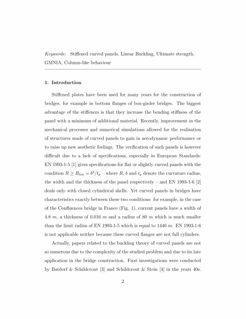
Concerning loading conditions, the study is limited to a uniform com-
pression in the longitudinal direction as it is the dominant loading in bottom
flange panels. It is applied not only to the main panel, but also to the stiffen-
ers due to their participation in the overall behaviour of the structure (Fig.
4). In fact, in a bridge, the compressive forces acting on the flange come
through the diaphragms and webs that connect the upper and lower panels
6
of the box girder. By construction, the stiffeners, in most cases, are continu-
ous and attached by welding to diagrams: therefore they are also subjected
to the compressive load.
Figure 4: Loading condition and corresponding typical stiffener/diaphragm connection.
The curved panels are discretized with eight-nodes elements Shell 281
[15]. This type of element is well-suited for linear, large rotation and large
strain nonlinear applications. Moreover, Shell 281 uses an advanced shell
formulation that accurately incorporates initial curvature effects. This for-
mulation offers improved accuracy in curved shell structure simulations and
converges faster than plate elements Shell 181 (Braun [16]). A fine mesh with
more than 30 elements per panel edges is used to reduce the discretisation
error.
The panels are all made of steel which is assumed to be elastic perfectly
plastic for the material non-linear analysis (MNA) and elastic-plastic with
linear strain hardening as indicated in EN 1993-1-5 C.6 for the material
non-linear second-order analyses with initial imperfections (GMNIA). The
Young modulus E and Poissons ration ν are taken equal to 210 GPa and 0.3
respectively. The steel grade is S355.
7
The basic configuration of the studied panels is taken similar to that of the
Confluences bridge. It has a fixed width b of 4800 mm with a thickness tp of
12 mm. The stiffeners are regularly spaced by a distance d of 600 mm (there
are thus 8 stiffeners in total). The curvature, the length of the panels and the
geometry of the stiffeners (T or simple flat) are the variable parameters whose
influence on the buckling behaviour of stiffened curved panels is investigated
in the following sections.
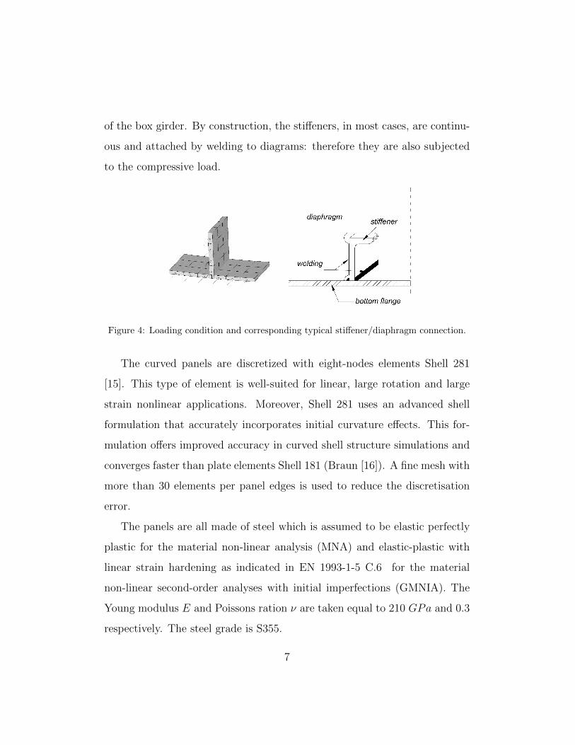
3. Linear buckling analysis
A series of linear buckling analyses is carried out to evaluate the buckling
strength and to examine typical buckling modes of stiffened curved panels.
The results are presented in Fig. 5 where the first buckling critical stress is
plotted as a function of the global curvature parameter Z = b2/Rtp.
Figure 5: Values and shapes of the first buckling mode depending on the curvature.
8

It is first noticed that the curvature increases the buckling stress, from
the value of the stiffened flat plate (where Z = 0) to a higher one for high
curvatures. The asymptotic value of the critical stress can be assumed to
follow a straight line, which, as believed by Soderquist [17], converges toward
the buckling stress of a full longitudinal stiffened cylinder.
Fig. 5 shows that the curvature modifies also the buckling shape. The
higher the curvature, the higher the number of half-waves m in the circumfer-
ential direction (from m = 1 for flat plates to m = 3 for Z = 192). This type
of buckling is in accordance with the observations of Schildcrout & Stein [4]
and is very similar to the overall buckling mode of stiffened cylinders under
axial compression.
Table 1: Coupled effect of aspect ratio and curvature on the relative buckling stress.
Z\α 1.0 1.5 2.0 3.0
0 1.00 1.00 1.00 1.00
6.4 1.11 1.12 1.13 1.11
38.4 1.21 1.36 1.47 1.50
96 1.60 2.16 3.17 3.75
192 2.14 3.30 4.52 6.53
384 3.11 5.69 8.80 10.99
The influence of the curvature is however not independent from other pa-
rameters. Indeed, table 1 presents the ratio of curved to flat panels buckling
stress σZcr/σ
∞cr in function of two parameters: the curvature Z and the aspect
ratio α = a/b. It is found that there is a significant interaction between
these two parameters: the influence of curvature is greater if the plate length
9

increases. For example, for a square panel (α = 1), the buckling stress for
curved panels (Z = 384) is three times that of a flat plate with the same
dimensions (Z = 0). This factor is equal to 11 if the aspect ratio α is set
equal to 3.
It is thus concluded that the curvature increases the elastic buckling re-
sistance of curved stiffened plates. The higher the curvature, the greater
the effect. The curvature also changes the shape of buckling: the number
of half-waves in the circumferential direction increases with the curvature.
Moreover, there is evidence of a strong positive interaction of the aspect
ratio and the curvature.
4. Ultimate strength
The ultimate strength of the panels is evaluated numerically using non-
linear analysis including geometrical and material imperfections (GMNIA).
These simulations are conducted using the arc-length method which allow
to follow the load-displacement curve when entering into the post-buckling
regime until the ultimate strength is reached. For such an iterative method,
it is necessary to select suitable criteria (L2-norm of force and moment) for
the convergence and the termination of the calculus. The criterion is thus
reached when the actual residual is lower than 0.5 % of the initial residual
which is appropriate for most engineering applications. The effect of cur-
vature is investigated via three important parameters (initial imperfection,
aspect ratio and the relative flexural stiffness of the stiffener), issued from
the parametric study on stiffened panels by Grondin et al. [18]; Ghavami et
al. [19] and on parabolic curved panels by Khedmati & Edala [10].
10

4.1. Influence of imperfections
As in many stability problems, the modelling of initial imperfections is
important. Typical imperfection of cylindrical panel studied by Soderquist
[17] are shown in Fig. 6. It is noticed that the differences of the local
curvature radii are significant, the maxima difference (4R = Rmax−Rmin
Rnominal)
reaching 20.5 %. It is also noticed that imperfections concentrate in the
vicinity of stiffeners. It appears hence necessary to take these imperfections
into account for calculating the ultimate strength of the panel. However, the
distribution of imperfections depends on so many parameters, that practically
the actual pattern can only be the result of a standardization process.
Figure 6: Contour mapping of the local curvature radii measured by Soderquist [17].
11
Taking into account the fact that the fabrication process of curved panels
is similar to that of plates, it seems reasonable to use the equivalent initial
imperfection given by EN 1993-1-5. To validate this assumption, a sensitivity
analysis is conducted based on the suggestions of EN 1993-1-5 table C.2.
Several models of imperfection are taken based on:
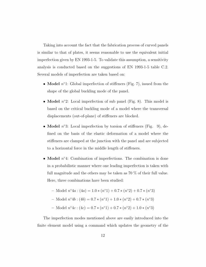
• Model n◦1: Global imperfection of stiffeners (Fig. 7), issued from the
shape of the global buckling mode of the panel.
• Model n◦2: Local imperfection of sub panel (Fig. 8). This model is
based on the critical buckling mode of a model where the transversal
displacements (out-of-plane) of stiffeners are blocked.
• Model n◦3: Local imperfection by torsion of stiffeners (Fig. 9), de-
fined on the basis of the elastic deformation of a model where the
stiffeners are clamped at the junction with the panel and are subjected
to a horizontal force in the middle length of stiffeners.
• Model n◦4: Combination of imperfections. The combination is done
in a probabilistic manner where one leading imperfection is taken with
full magnitude and the others may be taken as 70 % of their full value.
Here, three combinations have been studied:
– Model n◦4a : (4a) = 1.0 ∗ (n◦1) + 0.7 ∗ (n◦2) + 0.7 ∗ (n◦3)
– Model n◦4b : (4b) = 0.7 ∗ (n◦1) + 1.0 ∗ (n◦2) + 0.7 ∗ (n◦3)
– Model n◦4c : (4c) = 0.7 ∗ (n◦1) + 0.7 ∗ (n◦2) + 1.0 ∗ (n◦3)
The imperfection modes mentioned above are easily introduced into the
finite element model using a command which updates the geometry of the
12
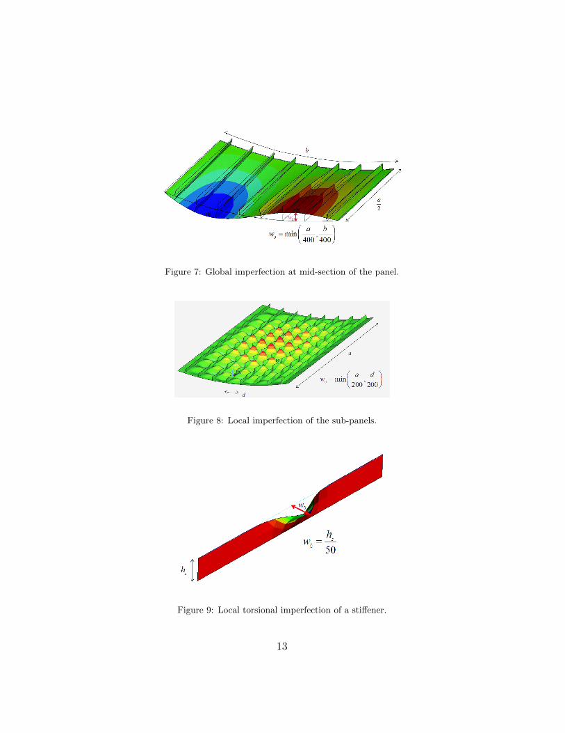
Figure 7: Global imperfection at mid-section of the panel.
Figure 8: Local imperfection of the sub-panels.
Figure 9: Local torsional imperfection of a stiffener.
13

finite element model according to the displacement results of the previous
analysis and creates a revised geometry. This command works on all nodes
(default) or on a selected set of nodes. If this command is issued repeatedly,
it creates a revised geometry of the finite element model in a cumulative fash-
ion, i.e. it adds displacement results on the previously generated deformed
geometry.
Table 2: Influence of various shape imperfections on the ultimate strength.
α n◦1 n◦2 n◦3 n◦4a n◦4b n◦4c
0.75 0.717 0.801 0.965 0.720 0.746 0.744
1.00 0.666 0.732 1.000 0.662 0.674 0.679
2.00 0.515 0.761 0.953 0.511 0.510 0.508
The results of a study conducted for a panel with a 10 m radius are
presented in table 2 for three values of the aspect ratio α (essentially in the
middle range of length where the imperfections have the most influence).
The ultimate strengths of panels are identified for each aspect ratio as the
minimum value in table 2. Their analyses bring to the following remarks:
• The ultimate load varies with the form of imperfection. The maximum
percentage difference between the largest and the smallest value can
reach up to 47 % (for α = 2).
• The model of imperfection based on the local imperfection of stiffener
(model n◦3) has a very limited influence on the ultimate load.
• In the studied example, model n◦1 is nearly the most critical one for
14

all cases (with a maximum deviation from the smallest value of only
1.4 % when α = 2). The global imperfection is thus the dominant
imperfection. This strong influence can be understood considering that
this imperfection mode introduces compression in the stiffener which is
a potentially unstable configuration (Fig. 10).
Figure 10: Influence of global imperfections on the stresses in the stiffener.
In conclusion, it has been shown that the influence of initial imperfection
on the value of the ultimate strength can be relatively important. For com-
plex structures that consist of several secondary structures such as stiffened
panels, it is difficult to find the most critical mode without a comprehensive
analysis of all possible modes of imperfections. However, for open cross-
section of stiffeners, it seems reasonable to assume that the global buckling
of stiffener’s model (alone or together with secondary local imperfection of
sub-panels) is dominant. This mode of imperfection will thus be used in the
next sections.
15

4.2. Influence of the aspect ratio
In the case of stiffened flat plates, the aspect ratio α = a/b is an important
parameter. Indeed, stiffened plates generally have a column-like behaviour
for small values of α and a plate-like behaviour for large values of α. Fig. 11
shows the ultimate loads as function of the aspect ratio α for three values
of the radius of curvature: (1) R = 1920 m for which the global curvature
parameter Z = b2/Rtp = 1; (2) R = 30 m for which the local curvature
parameter Zd = d2/Rtp = 1; and (3) R = 10 m for a configuration of
very curved panels (rarely used in bridge construction). The first two cases
(R = 1920 m and R = 30 m) are selected to examine the limits of EN 1993-
1-5 whose ultimate strength for a similar stiffened plate is also presented (see
continuous curve in Fig. 11).
Figure 11: Effect of curvature on the ultimate strength.
16

These results, which are raw values from the finite element simulations
without any consideration of safety factor, bring the following remarks:
• First of all, the curvature increases the ultimate strength of panels,
especially in the range of intermediate panels (1 < α < 2). This
confirms the observations in the literature mentioned above [5].
• The ultimate strength of the stiffened curved panels is significantly
influenced by the aspect ratio α as in the case of stiffened flat panel: it
decreases when α increases.
• For Z = b2/Rtp = 1, the numerical results can be estimated by Euro-
pean standard (EN 1993-1-5) prediction’s curve. It is thus concluded
that the domain of validity of EN 1993-1-5 defined by the condition
R > b2/tp is satisfactory and secure. Also, the risk of under-estimation
for the intermediate panels can be corrected by using De Ville de Goyet
et al. [20] proposition, which is, in our opinion, the best interpolation
behaviour of stiffened plates (see the discussion in [21]).
• For Zd = d2/Rtp = 1, the numerical results are all above of the Euro-
pean standard curve (about 20 % in average with a maximum of 38 %).
This observation is interesting and motivates a proposition for expand-
ing the scope of EN 1993-1-5, in which the value of the parameter b
in the condition b2/tp < R is replaced by the value of d in the case of
stiffened panels. With this modification, most stiffened curved plates
in the field of structures can be covered, on the safety side, by recom-
mendation for stiffened flat plate (by neglecting the increasing effect of
curvature).
17

• The increase of the ultimate load is higher if the curvature is significant.
For example, if R = 10 m, the ultimate load is double compared to that
of a flat plates (120 % higher more precisely) for intermediate panel and
about 70 % for long panels. Not considering here its effect becomes thus
very unfavourable.
4.3. Influence of the stiffeners rigidity
According to the work of Bedair [22], the rigidity of the stiffeners is an
important parameter influencing the behaviour of stiffened plates. In this
section, the behaviour of panels with simple flat stiffeners is thus compared to
that of panels with T-shape stiffeners. Their cross section is chosen identical
(A = 24 cm2) but their second moment of area is different (IT−shape =
0.30 · 108 mm4 > Iflat plate = 0.18 · 108 mm4). The values of the ultimate
strength for flat plates are presented in Fig. 12a which shows that the use
of T-shape stiffeners is more efficient than that of simple flat stiffeners with
a gain of about 40 % for α = 1. Indeed, the flanges of T-shape stiffeners are
located far away from the panel neutral axis, they provide thus more bending
inertia than flat plate stiffeners (about 6 times).
However, this gain becomes less significant when the curvature increases:
it is of only 8 % when R = 10 m (see Fig. 12). The reason is that the
position of the center of gravity of the section relatively to the panel changes
with the curvature: from 26.8 mm for flat plate (R = ∞) to 121.9 mm for
R = 10 m. The curvature raises the center of gravity toward the center of
curvature, which is closer to the stiffener flanges (see Fig. 13). This leads to
a decrease of the second moment of area induced by the stiffeners, therefore
the efficiency of the T stiffeners is reduced.
18

Figure 12: Influence of the rigidity of the stiffener: R =∞ (left), R = 10 m (right).
Figure 13: Influence of the curvature on the centre of gravity height and the inertia Isl.
Table 3 shows some typical values of moments of inertia (calculated on
the total cross section). As the second moment of area is linked directly
to the stiffness of the panel, these values are very interesting and can thus
explain most previous remarks. Indeed for a flat plate, using stiffeners is
extremely useful because it increases the structural strength without making
the structure heavier. An increase of 190 times the inertia of the panel is
obtained by simply adding single flat stiffeners. The use of T-shape stiffen-
ers instead of flat ones induces then an additional increase of 61 %, which
explains the results in Fig. 12b.
19
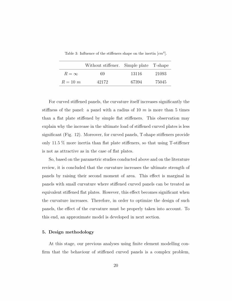
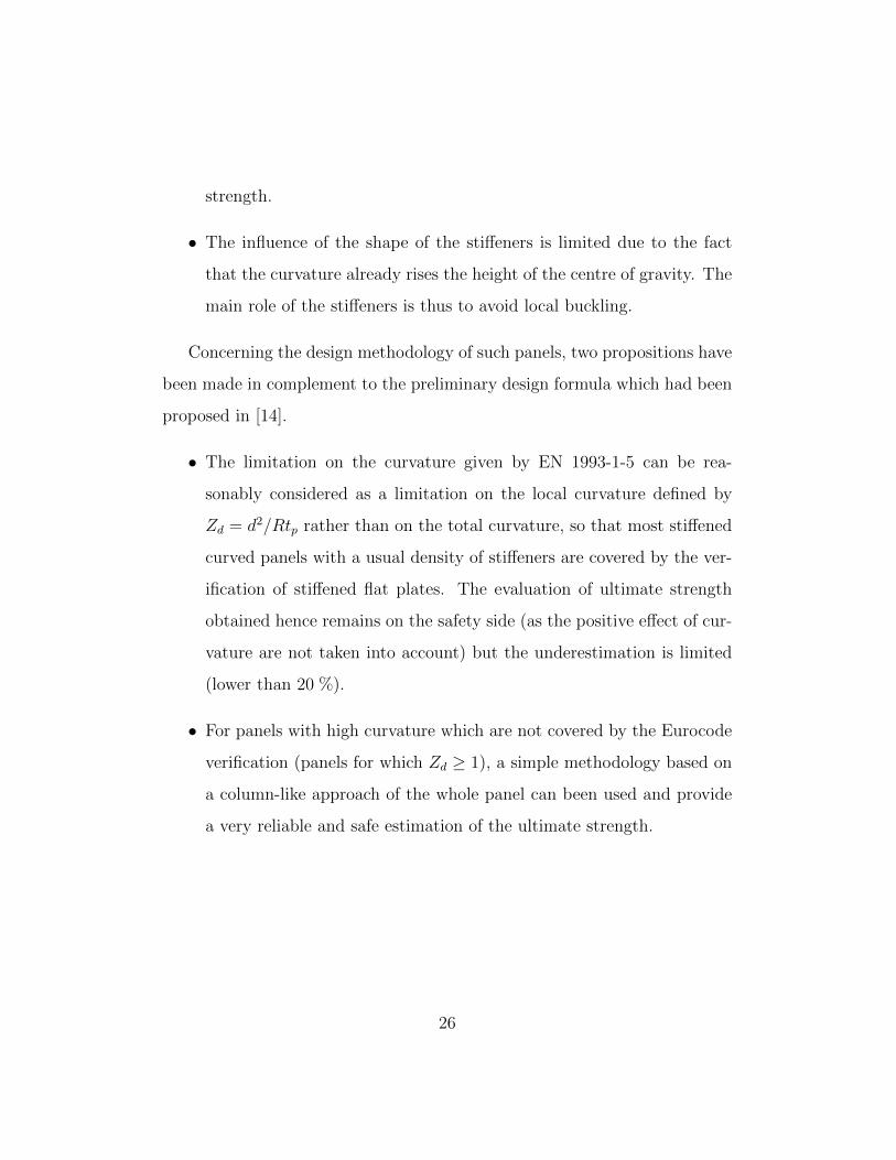
Table 3: Influence of the stiffeners shape on the inertia [cm4].
Without stiffener. Simple plate T-shape
R =∞ 69 13116 21093
R = 10 m 42172 67394 75045
For curved stiffened panels, the curvature itself increases significantly the
stiffness of the panel: a panel with a radius of 10 m is more than 5 times
than a flat plate stiffened by simple flat stiffeners. This observation may
explain why the increase in the ultimate load of stiffened curved plates is less
significant (Fig. 12). Moreover, for curved panels, T-shape stiffeners provide
only 11.5 % more inertia than flat plate stiffeners, so that using T-stiffener
is not as attractive as in the case of flat plates.
So, based on the parametric studies conducted above and on the literature
review, it is concluded that the curvature increases the ultimate strength of
panels by raising their second moment of area. This effect is marginal in
panels with small curvature where stiffened curved panels can be treated as
equivalent stiffened flat plates. However, this effect becomes significant when
the curvature increases. Therefore, in order to optimize the design of such
panels, the effect of the curvature must be properly taken into account. To
this end, an approximate model is developed in next section.
5. Design methodology
At this stage, our previous analyses using finite element modelling con-
firm that the behaviour of stiffened curved panels is a complex problem,
20

especially due to the interaction of the curvature, the relative rigidity of
stiffeners and the imperfections. The development of a simple (i.e. suited
for hand-calculation) and reliable (i.e. in good agreement with numerical re-
sults and with Eurocode formalism) method which would give the ultimate
resistance of such panels with a reasonable precision becomes thus desirable
for practical applications by engineers.
5.1. Choice of the methodology
As the curvature of panels used for bridge construction is not significant,
the solution is naturally derived from the model of resistance for stiffened
flat plates. According to EN 1993-1-5, the collapse load can be evaluated
by interpolation of two distinct asymptotic behaviours: a column-like be-
haviour without any post-buckling resistance and plate-like behaviour with
post-buckling resistance.
In a previous work [23], the authors had shown that, for unstiffened curved
panels under uniform axial compression, the limit proposed by EN 1993-1-
5 for the curvature Z (Z = b2/Rtp ≤ 1) was satisfactory. For stiffened
curved panels, numerical simulations detailed in section 4.2 have shown that
this limit can actually be extended to the local curvature of the panels Zd
defined by d2/Rtp where d denotes the distance between stiffeners. Indeed
within this range, neglecting the beneficial effect of curvature leads to an
underestimation of the ultimate strength which remains smaller than 20 %,
as can be seen in Fig. 11.
For higher local curvatures (i.e. for Zd ≥ 1), the positive effect of cur-
vature can no longer be neglected. So, depending on the design stages, two
different methodologies can be used. In a preliminary design stage, the for-
21

mula developed in [14] provides a reliable and straightforward way to evaluate
the ultimate strength. In a final design stage, engineers will prefer to use a
methodology closer to the Standards formalism. Therefore, considering that:
i) the range of the aspect ratios in civil engineering applications is reduced
(for example, in the Confluence bridge in Fig. 1, the 300 curved panels
of the girder have an aspect ratio α = a/b smaller than 1.25,
ii) for reduced aspect ratios stiffened curved panels failure is governed by a
column-like buckling,
a criterion based on column-like behaviour will be developed in the coming
section.
Such a criterion has already been adopted in several standards for stiff-
ened plates [24], for simplicity reason and also because it always provides
an estimation of the ultimate strength on the safety side. Indeed, the basis
of the column-like approach for flat panels is to treat a stiffened panel as
a series of unconnected compression ”struts” where a ”strut” consists of a
longitudinal stiffener acting together with the associated width of plate be-
tween stiffeners. The two unloaded edges of a ”strut” are assumed to be
free. No membrane effects ,which are characteristic of panels, can take place
and hence there is no post-buckling reserve. As a consequence, this approach
provides a lower bound of the ultimate strength.
5.2. Ultimate strength by column-like behaviour
The proposed methodology thus consists in considering that the ultimate
strength of curved stiffened panels under uniform axial compression can be
evaluated from a standard column buckling problem by EN 1993-1-1 [25].
22

Therefore, the first step consists in the determination of elastic buckling
stress σcr , also known as Euler stress:
σcr =π2EIslAsla2
(1)
As for stiffened flat panels, Asl and Isl are the area and the second mo-
ment of inertia for longitudinal bending of the ”strut” model. However, for
stiffened curved panels, it is not relevant to disconnect the stiffeners and to
analyse every column separately. Indeed, as seen in section 4.3, the curvature
itself has a very strong influence on the bending inertia of the stiffened panel.
As presented in Fig. 13, the inertia of the whole stiffened plate is equal to the
sum of those of 8 strut models (IR=∞sl = 21093 cm4 = 8·Isl,strut = 8·2636 cm4)
whereas it is not the case for the curved stiffened panels R = 10 m (IR=10 msl =
75045 cm4 > 8 · Isl,strut = 8 · 2550 cm4 = 20400 cm4). For curved panels,
the appropriate strut model is thus the whole panel and the area and inertia
must be evaluated on the whole model.
Then, in the second step, this elastic buckling stress is used to determine
the reduced slenderness λ taking into account class 4 portions of the section
through the introduction of the ratio between the effective area Ac,eff (evalu-
ated by the standard Eurocode procedure) and the gross cross-sectional area
Asl.
λ =
√Ac,eff
Asl
fyσcr
(2)
Afterwards, the imperfection parameter αe is evaluated from the gyration
radius i =√Isl/Asl of the whole panel and from the characteristic eccen-
tricity of the loading e which is defined by max(G1 − G;G) where G is the
distance between the centre of gravity of the stiffened panel and the middle
23

plane of the panel and G1 is the distance between the centre of gravity of the
stiffeners only and the middle plane of the panel .
αe = α +0.09
i/e(3)
In most cases, α is equal to 0.49 as the panels are generally stiffened by open
sections and follow the buckling curve c) of EN 1993-1-1 .
Then the reduction factor χc is obtained from the parameter φ by:
χc =1
φ+
√φ2 − λ2
with φ = 0.5[1 + αe
(λ− 0.2
)+ λ
2]
(4)
And finally the ultimate strength of the curved panel is deduced:
NRd = χc · Ac,eff · fy (5)
Fig. 14 shows the comparison of the proposed methodology and numerical
simulations for panels with a curvature radius of 10 m, a thickness of 12 mm
and a width of 4.8 m stiffened by 8 simple flats separated by 600 mm with
a height hsof 150 mm and a thickness tsof 16 mm (which corresponds to
Z = b2/Rtp = 192 ≥ 1 and to Zd = d2/Rtp = 3 ≥ 1). It can be seen that the
agreement is very good in the studied range of aspect ratio (and becomes less
accurate for higher values of α). It appears also that the estimation of the
ultimate strength is much better than the one obtained with the Eurocode
for stiffened flat plates. It is thus concluded that the column-like approach
provides a reliable and safe method for the estimation of the strength of
curved stiffened panels.
24

Figure 14: Ultimate strength of curved stiffened panels by a column-like approach.
6. Conclusion
The buckling behaviour of stiffened curved panel subjected to a uniform
axial compression has been investigated in the present paper, focusing on the
practical range of bridge engineering applications. In comparison with stiff-
ened flat plates which have been studied for a long time, the most significant
effects of curvature can be summarised as follow.
• For elastic buckling, the curvature modifies the global shape of the
buckling mode. The higher the curvature, the higher the number of
half-waves in circumferential direction. The buckling mode for a very
high curvature is hence very close to that of longitudinal stiffened cylin-
der.
• The curvature increases the second moment of inertia leading to a
higher elastic buckling stress of curved panels and to a higher ultimate
25
strength.
• The influence of the shape of the stiffeners is limited due to the fact
that the curvature already rises the height of the centre of gravity. The
main role of the stiffeners is thus to avoid local buckling.
Concerning the design methodology of such panels, two propositions have
been made in complement to the preliminary design formula which had been
proposed in [14].
• The limitation on the curvature given by EN 1993-1-5 can be rea-
sonably considered as a limitation on the local curvature defined by
Zd = d2/Rtp rather than on the total curvature, so that most stiffened
curved panels with a usual density of stiffeners are covered by the ver-
ification of stiffened flat plates. The evaluation of ultimate strength
obtained hence remains on the safety side (as the positive effect of cur-
vature are not taken into account) but the underestimation is limited
(lower than 20 %).
• For panels with high curvature which are not covered by the Eurocode
verification (panels for which Zd ≥ 1), a simple methodology based on
a column-like approach of the whole panel can been used and provide
a very reliable and safe estimation of the ultimate strength.
26

Nomenclature
α aspect ratio (α = a/b)
χc column buckling reduction factor
λ relative slenderness parameter
Asl gross cross sectional area of the whole panel
b width of a stiffened panel
d distance between stiffeners
fy yield strength
Isl second moment of the area of whole panel
NRd design resistance force
ts stiffener thickness
Z,Zd global and local curvature parameter (Z = b2/Rtp, Zd = d2/Rtp)
σcr elastic buckling stress for the equivalent strut model
a length of a stiffened panel
Ac,eff effective cross sectional area
E elastic modulus
hs height of stiffeners
tp panel thickness
27
List of Figures
1 Bottom flange made of stiffened curved panels, Confluences
Bridge, France. . . . . . . . . . . . . . . . . . . . . . . . . . . 3
2 Effect of curvature on the axial compressive strength of stiff-
ened panels [8]. . . . . . . . . . . . . . . . . . . . . . . . . . . 4
3 Characteristics of a stiffened curved panel simply supported
on all edges. . . . . . . . . . . . . . . . . . . . . . . . . . . . . 6
4 Loading condition and corresponding typical stiffener/diaphragm
connection. . . . . . . . . . . . . . . . . . . . . . . . . . . . . 7
5 Values and shapes of the first buckling mode depending on the
curvature. . . . . . . . . . . . . . . . . . . . . . . . . . . . . . 8
6 Contour mapping of the local curvature radii measured by
Soderquist [17]. . . . . . . . . . . . . . . . . . . . . . . . . . . 11
7 Global imperfection at mid-section of the panel. . . . . . . . . 13
8 Local imperfection of the sub-panels. . . . . . . . . . . . . . . 13
9 Local torsional imperfection of a stiffener. . . . . . . . . . . . 13
10 Influence of global imperfections on the stresses in the stiffener. 15
11 Effect of curvature on the ultimate strength. . . . . . . . . . . 16
12 Influence of the rigidity of the stiffener: R = ∞ (left), R =
10 m (right). . . . . . . . . . . . . . . . . . . . . . . . . . . . 19
13 Influence of the curvature on the centre of gravity height and
the inertia Isl. . . . . . . . . . . . . . . . . . . . . . . . . . . . 19
14 Ultimate strength of curved stiffened panels by a column-like
approach. . . . . . . . . . . . . . . . . . . . . . . . . . . . . . 25
28
List of Tables
1 Coupled effect of aspect ratio and curvature on the relative
buckling stress. . . . . . . . . . . . . . . . . . . . . . . . . . . 9
2 Influence of various shape imperfections on the ultimate strength. 14
3 Influence of the stiffeners shape on the inertia [cm4]. . . . . . . 20
29

References
[1] EN 1993-1-5 : Design of steel structures, Part 1-5 : Plated structural
elements. CEN, Brussels; 2007.
[2] EN 1993-1-6 : Design of steel structures, Part 1-6 : Strength and sta-
bility of shell structures. CEN, Brussels; 2007.
[3] Batdorf S, Schildcrout M. Critical axial-compressive stress of a curved
rectangular panel with a central chordwise stiffener. Tech. Rep.; 1948.
[4] Schildcrout M, Stein M. Critical axial-compressive stress of a curved
rectangular panel with a central longitudinal stiffener. Tech. Rep.;
NACA Technical Note 1879; 1949.
[5] Becker H. Handbook of structural stability. Part VI: Strength of stiffened
curved plates ans shells. Tech. Rep.; New York University, Washington;
1958.
[6] Gall H. Compressive strength of stiffened sheets of aluminum alloy.
Ph.D. thesis; Massachusetts Institute of Technology; 1930.
[7] Lundquist E. Comparison of three methods for calculating the com-
pressive strength of flat and slightly curved sheet and stiffener combi-
nations. Tech. Rep.; National Advisory Committee for Aeronautics, TC
455; 1933.
[8] Ramberg W, Levy S, Fienup K. Effect of curvature on strength of
axially loaded sheet-stringer panels. Tech. Rep.; NACA-Technical note
944; 1944.
30

[9] Cho S, Park H, Kim H, Seo J. Experimental and numerical investigations
on the ultimate strength of curved stiffened plates. In: Proceeding
10th International Symposium on Practical Design of Ships and Other
Floating Structures. 2007,.
[10] Khedmati M, Edalat P. A numerical investigation into the effects of
parabolic curvature on the buckling strength and behaviour of stiffened
plates under in-plane compression. Latin American Journal of Solids
and Structures 2010;7(3).
[11] Park J, Iijima K, Yao T. Estimation of buckling and collapse behaviours
of stiffened curved plates under compressive load. International Society
of Offshore and Polar Engineers, USA; 2008,.
[12] Zimmermann R, Klein H, Kling A. Buckling and postbuckling of stringer
stiffened fibre composite curved panels: tests and computations. Com-
posite Structures 2006;73(2):150–61.
[13] Zimmermann R, Rolfes R. Posicoss-improved postbuckling simulation
for design of fibre composite stiffened fuselage structures. Composite
Structures 2006;73(2):171–4.
[14] Tran K, Douthe C, Sab K, Davaine L, Dallot J. A preliminary design for-
mula for the strength of stiffened curved panels by design of experiment
method. Thin-Walled Structures 2014;79:129–37.
[15] ANSYS . User’s theory manual v11. 2007.
[16] Braun B. Stability of steel plates under combined loading. Ph.D. thesis;
University of Stuttgart; 2010.
31
[17] Soderquist A. Experimental investigation of stability and post buckling
behaviour of stiffened curved plates. Institute of Aerophysics, University
of Toronto; 1960.
[18] Grondin G, Elwi A, Cheng J. Buckling of stiffened steel plates - A para-
metric study. Journal of Constructional Steel Research 1999;50(2):151–
75.
[19] Ghavami K, Khedmati M. Numerical and experimental investigation on
the compression behaviour of stiffened plates. Journal of Constructional
Steel Research 2006;62(11):1087–100.
[20] De Ville De Goyet V, Maquoi R, Bachy F, Andre I. Ultimate load of
stiffened compressed plates: Effects of some parameters and discussion
concerning the ec3 rules. In: Proceedings of the Third European Con-
ference on Steel Structures; vol. 1. 2002, p. 591–600.
[21] TRAN K. Etude de la stabilite et de la resistance des toles courbes
cylindriques. applications aux ouvrages d’art. Ph.D. thesis; Universite
Marne-La-Vallee; 2012.
[22] Bedair O. Analysis and limit state design of stiffened plates and shells:
A world view. Applied Mechanics Reviews 2009;62(2):020801–16.
[23] Tran K, Davaine L, Douthe C, Sab K. Stability of curved panels un-
der uniform axial compression. Journal of constructional steel research
2012;69(1):30–8.
32

[24] Bonello M, Chryssanthopoulos M, Dowling P. Ultimate strength de-
sign of stiffened plates under axial compression and bending. Marine
structures 1993;6(5-6):533–52.
[25] EN 1993-1-1 : Design of steel structures, Part 1-1 : General rules and
rules for buildings. CEN, Brussels; 2005.
33