Embed Size (px)
Citation preview

Buckling Analysis of Thin Carbon/Epoxy Plate by Using FEA
1A.Joshi Gowri Sankar,
2Dr. P. Ravinder Reddy,
3Ch.V.Sushma
1P.G.Student,
2Prof&H.O.D,
3P.G.student, Mechanical Engineering Dept., Chaitanya Bharathi
Institute of Technology, Hyderabad-75,AndraPradesh,India.
ABSTRACT
In this paper a carbon/epoxy composite thin plate having
four lamina with fiber orientation (00/90
0/90
0/0
0) is
selected for analysis. The plate has length a, width b&
thickness t. The Nature of buckling load factors with
respect to Aspect ratio is studied. In the next step nature
of buckling load factors with respect to t/b ratio is studied.
The commercial finite element analysis software ANSYS
has been successfully executed and the finite element
model is validated. Buckling load factors have been
determined for different aspect ratio by introducing
cutouts and multiple holes (d/b ratio & d/d1 ratio). The
buckling load factor decreases as the aspect ratio
increases. As the d/b ratio increases, buckling load factor
decreases. It was seen that buckling load factor decreases
with increase of d1/d ratio. Since localization of stress
concentration is reduced by providing the multiple holes
around the cut out shape. The reduction of the buckling
load due to the presence of a cutout is found to be
significant. It is noted that the presence of cutout lowers
the buckling load factor.
Key words: Buckling load factor, carbon/epoxy composite
plate, aspect ratio, t/b ratio, d/b ratio, d/d1 ratio.
1. INTRODUCTION
In many engineering structures such as columns,
beams, or plates, their failure develops not only
from excessive stresses but also from
buckling.Buckling behavior significantly
changes with change in aspect ratio, d/b ratio,
d1/d ratio. Plate seems to work as a Column of
finite width at higher aspect ratio. If we decrease
aspect ratio, there is also a limit below which
failure does not take place by elastic
buckling.A.K. Shrivastava & R.K. Singh in
1998 [1] studied the effect of Aspect ratio on
buckling behavior.In this paper an attempt has
been made to study the effectof aspect ratio, d/b
& d1/d on the buckling of laminated Composite
plates by FEA using ANSYS.
2. NUMERICAL ANALYSIS
This work is to find buckling load factors of
carbon/epoxy rectangular plate subjected to
uniaxial compression using finite element
analysis ANSYS 11. The plate has length a,
width b & thickness t. The width of plate is
taken as taken as constant b= 1m. The analysis
is done in the following cases:
Case1:
The Nature of buckling load factor with respect
to Aspect ratio is studied. Here Aspect ratio
varies from 2 to 12.
In the next step nature of buckling load factor
with respect to t/b ratio is studied. Here the
buckling factors at various t/b ratio’s such as
1/20, 1/40, 1/60, 1/80 and 1/100 is calculated
using ANSYS. The effect of buckling factor,
stress concentrations in the plate is studied.
Case2:
Next the analysis is done by placing center hole
in the plate and by varying its diameter (d). The
Nature of buckling load factor with respect to
d/b ratio is studied. The effect on
515
International Journal of Engineering Research & Technology (IJERT)
IJERT
IJERT
ISSN: 2278-0181
www.ijert.orgIJERTV2IS90354
Vol. 2 Issue 9, September - 2013

stressconcentration zones in the plate are studied
due to center hole.
Case3:
Further the work is extended to the analysis by
placing multiple holes in the plate and by
varying their diameters (d1). The Nature of
buckling load factor with respect to d1/d ratio is
studied. The effect on stress concentration zones
in the plate is studied due to multiple holes.
3. ELEMENT DESCRIPTION
In this study, 8 node linear layer shell 99 was
selected as the element type.SHELL99 may be
used for layered applications of a structural shell
model. While SHELL99 does not have some of
the nonlinear capabilities of SHELL91, it
usually has a smaller element formulation time.
SHELL99 allows up to 250 layers. If more than
250 layers are required, a user-input constitutive
matrix is available.
The element has six degrees of freedom at each
node: translations in the nodal x, y, and z
directions and rotations about the nodal x, y, and
z axes. In the Fig 2 the geometry, node
locations, and the coordinate system for this
element are shown.
Fig 1: Element geometry of linear layer shell 99
4. FINITE ELEMENT ANALYSIS
Finite element analysis includes three steps. (a)
Preprocessing (b) analysis (c) post processing.
Preprocessing includes modeling of the plateand
applying boundary conditions like constraints,
symmetry conditions, and loads. The
carbon/epoxy plate is considered as
anorthotropic material with following
properties:
To create model first area is created. Then the
plate is meshed. Then load is applied on the
plate. The plate is subjected to clamped-free
boundary conditions. The left end of the plate is
constrained by all degrees of freedom and to the
right end a buckling load of 1 N is applied.Unit
loads are usually sufficient (that is, actual load
values need not be specified). The eigenvalues
calculated by the buckling analysis represent
buckling load factors. Therefore, if a unit load is
specified, the load factors represent the buckling
loads. Hereanalysis is done in two stages. In the
first stage static analysis is done and Prestress
effects [PSTRES] must be activated. Eigenvalue
buckling analysis requires the stress stiffness
matrix to be calculated. In the second stage
Eigen buckling analysis done. After solving the
problem the mode shapes and normal stress
distribution is observed in the post
processor.The output from the solution mainly
consists of the eigenvalues, which are printed as
Young’s
modulus
(MPa)
E1=
139x103
E2=
11x103
E3=
11x103
Poission’s
ratio V12=0.32 V23=0.46 V13=0.32
Rigidity
modulus
(MPa)
G12=
4.7x10³
G23=
3.7x10³
G13=
4.7x10³
516
International Journal of Engineering Research & Technology (IJERT)
IJERT
IJERT
ISSN: 2278-0181
www.ijert.orgIJERTV2IS90354
Vol. 2 Issue 9, September - 2013

part of the printed output. The eigenvalues
represent the buckling load factors.
5. MESHED MODEL OF CARBON/
EPOXY PLATE AND MODE SHAPES:
Case1:
A composite plate having four lamina with
dimensions (a*b*t). Nature of buckling load
factor with respect to aspect ratio is studied.
Here Aspect ratio varies from 2to 12. Where a,
b, t are the length, width & thickness of the plate
respectively.
Fig2:Meshed model of carbon/epoxy plate with
aspect ratio a/b=2.
Applying loads to plate:
The fifth mode shape the plate is shown below
Fig3: mode shape 5 of plate of a/b=2, t/b=1/20
Case2:
The plate has a central circular cut out of
varying diameter, d. Here d/b ratio varies from
0.05 to 0.3, in the steps of 0.05. Nature of
buckling load factor with respect to d/b ratio
was studied.
Fig4: Meshed model of carbon/epoxy plate with
aspect ratio a/b=2, d/b= 0.3.
The fifth mode shape of plate with center hole is
shown below:
Fig5: mode shape 5 of carbon/epoxy plate with
aspect ratio a/b=2, d/b=0.3.
Case3:
The plate has a Centre hole, d along with
multiple holes of varying diameter d1. Here d1/d
ratio varies from 0.05 to 0.3, in the steps of 0.05.
517
International Journal of Engineering Research & Technology (IJERT)
IJERT
IJERT
ISSN: 2278-0181
www.ijert.orgIJERTV2IS90354
Vol. 2 Issue 9, September - 2013

Nature of buckling load factor with respect to
d1/d ratio was studied.
Fig6: Meshed model of carbon/epoxy plate with
aspect ratio a/b=2, d1/d= 0.3.
The fifth mode shape of plate with multiple
holes is shown in fig7.
Fig7: mode shape 5 of carbon/epoxy plate with
aspect ratio a/b=2, d1/d=0.3.
6. RESULTS AND DICUSSIONS
Case1:
The fig8 is showing the variation of mode 5
buckling factor at various t/b ratios vs. aspect
ratio. It is observed that as the t/b ratio decreases
the buckling factor decreases.As the t/ b ratio
decreased from 1/20 to 1/40 the buckling factor
nearly decreased by 7.8 times .As the t/ b ratio
decreased from 1/40 to 1/60 the buckling factor
nearly decreased by 3.4 times. As the t/ b ratio
decreased from 1/60 to 1/80 the buckling factor
nearly decreased by 2.34 times .As the t/ b ratio
decreased from 1/80 to 1/100 the buckling factor
nearly decreased by 1.95 times .So the buckling
factor decreases with the decrease in t/b ratio
and at the initial stages it is high such as 7.8 and
at the final stages it reduced to 1.95.
Fig8:Variation of mode 5 buckling factor vs.
aspect ratio at various t/b ratios
The variation of normal stresses in x direction
and their distribution in the plate at various
aspect ratios is shown in the figures below. It is
observed that as the aspect ratio increases the
stress effected zone decreases this is to be
compared with stress contraction in the plate due
to cut out and because of multiple holes.
518
International Journal of Engineering Research & Technology (IJERT)
IJERT
IJERT
ISSN: 2278-0181
www.ijert.orgIJERTV2IS90354
Vol. 2 Issue 9, September - 2013

Fig 9: contour plot with aspect ratio at a/b=2
Fig 10: contour plot with aspect ratio at a/b=4
Fig 11: contour plot with aspect ratio at a/b=6
Fig 12: contour plot with aspect ratio at a/b=8
Fig 13: contour plot with aspect ratio at a/b=10
Fig 14: contour plot with aspect ratio at a/b=12
Case2:
Hear d/b ratio various from 0.05 to 0.3. Nature
of buckling load factor with respect to d/b ratio
is studied. The of stress constration due to center
cut out is also studied.From the figure15 it
observed that the buckling factor decreases with
increases of aspect ratios for the plate with
center hole. Because of the hole in the plate the
buckling factor decreased when compared with
bear plate.
Fig 15:Buckling factor vs. a/b at various d/b
ratio
From the figure 16 it is observed that with
increase of d/b ratio from 0.05 the buckling
519
International Journal of Engineering Research & Technology (IJERT)
IJERT
IJERT
ISSN: 2278-0181
www.ijert.orgIJERTV2IS90354
Vol. 2 Issue 9, September - 2013

factor decreases up to 0.15 further slightly
increased up to 0.2 then decreased up to 0.3.
Fig 16:Mode5 buckling factors vs. d/b ratio
The below Figures shows the normal stress
distribution in x direction because of application
of buckling load to the plate with center hole. It
is observed that the stress concentration zone
increases in the plate because of the center hole.
It is to be decreased by incorporating small
multiple holes in the plate.
Fig 17: contour plot with a/b=2,d/b=0.05
Fig 18: contour plot with a/b=2,d/b=0.1
Fig 19: contour plot with a/b=2,d/b=0.15
Fig 20: contour plot with a/b=2,d/b=0.2
Fig 21: contour plot with a/b=2,d/b=0.25
Fig 22: contour plot with a/b=2,d/b=0.3
520
International Journal of Engineering Research & Technology (IJERT)
IJERT
IJERT
ISSN: 2278-0181
www.ijert.orgIJERTV2IS90354
Vol. 2 Issue 9, September - 2013
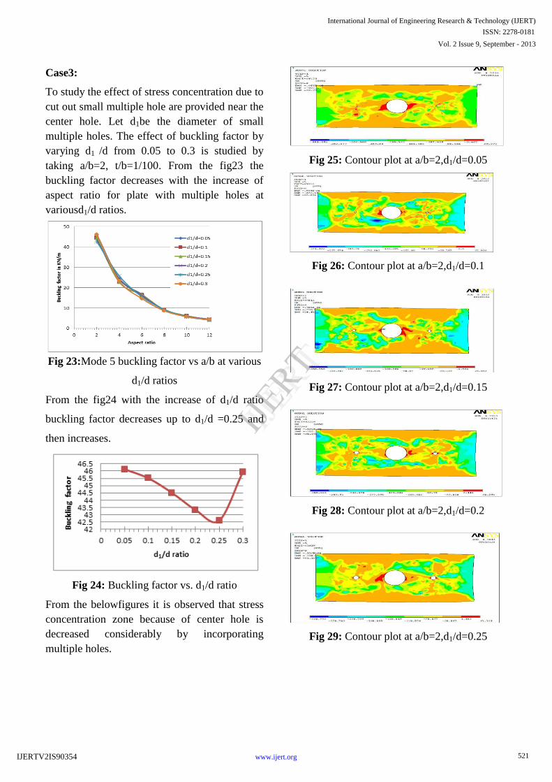
Case3:
To study the effect of stress concentration due to
cut out small multiple hole are provided near the
center hole. Let d1be the diameter of small
multiple holes. The effect of buckling factor by
varying d1 /d from 0.05 to 0.3 is studied by
taking a/b=2, t/b=1/100. From the fig23 the
buckling factor decreases with the increase of
aspect ratio for plate with multiple holes at
variousd1/d ratios.
Fig 23:Mode 5 buckling factor vs a/b at various
d1/d ratios
From the fig24 with the increase of d1/d ratio
buckling factor decreases up to d1/d =0.25 and
then increases.
Fig 24: Buckling factor vs. d1/d ratio
From the belowfigures it is observed that stress
concentration zone because of center hole is
decreased considerably by incorporating
multiple holes.
Fig 25: Contour plot at a/b=2,d1/d=0.05
Fig 26: Contour plot at a/b=2,d1/d=0.1
Fig 27: Contour plot at a/b=2,d1/d=0.15
Fig 28: Contour plot at a/b=2,d1/d=0.2
Fig 29: Contour plot at a/b=2,d1/d=0.25
521
International Journal of Engineering Research & Technology (IJERT)
IJERT
IJERT
ISSN: 2278-0181
www.ijert.orgIJERTV2IS90354
Vol. 2 Issue 9, September - 2013

Fig 30: Contour plot at a/b=2,d1/d=0.3
7. CONCLUSIONS
This study considers the buckling response of
laminated carbon/ epoxy with clamped-free
boundary conditions. The laminated composite
plates have varying aspect ratio, varying
thickness to breadth t/b ratio, cut out shape and
multiple holes and effect of stress concentration
is considered. From the present analysis, the
following conclusions are made:
It was noted that the buckling factor
decreases with increases of aspect ratio
As the t/b ratio decreases the buckling factor
decreases.
The presence of center hole causes decrease
in buckling factor and increase of stress
concentration zones.
The incorporation of multiple holes causes the
decrease in buckling factor and decrease in
stress concentration zones.
8. FUTURE SCOPE OF WORK
1. Providing multiple notches & removal of
material around the discontinuity is to be done.
2. Study Post buckling behavior of laminated
composite material, for which a nonlinear
analysis is to be performed.
9. REFERENCES
1. Timoshenko, J. Gere, Theory of Elastic Stability, McGraw-
Hill, International Book Company, 1961.
2. R. D. Mindlin,” Influence of rotary inertia and shear on
flexural motions of isotropic, elastic plates”, Journal of Applied
Mechanics Vol. 18 (Transaction ASME 73), 1951, pages 31-38.
3. A. V. Ravi Prakash, A. Adhitya Plato Sidharth, B. Prabu, and
N. Alagumurthi,“ Structural reliability of thin plates with
random imperfections subjected to uniform axial compression”,
Jordan Journal of Mechanical and Industrial engineering Vol. 4,
2010, pages 270-279.
4. Khaled M. EI- Sawy and Aly S. Nazmy,” Effect of aspect
ratio on the elastic buckling of uniaxially loaded plates with
eccentric holes”, Thin-Wall Structures (39), 2001, pages 983-
998.
5. V.Piscopo,“Refined Buckling Analysis of Rectangular Plates
under Uniaxial and Biaxial Compression”, World Academy of
Science, Engineering and technology. Vol. 70, 2010, pages 555-
562.
6. Composite Material & Structure by MadhujitMukhopadhyay,
University Press.
7. G.Garya and H. Zhao. Dynamic testing of fibre polymer
matrix composite plates under in-plane compression- Journal of
Composites: Part A 31 (2000) 835–840.
8.BuketOkutan Baba and AysunBaltaci. Buckling characteristics
of symmetrically and anti-symmetrically laminated composite
plates with central cutout,-Applayed Composite Materials –
14(2007):265–276
9. A K Sreevastva, R.K Singh. Effect of aspect ratio on buckling
of composite plates-.Journal of CompositesScience and
Technology59 (1999) 439-445
10. ChainarinPannok and PairodSinghatanadgid. Buckling
analysis of composite laminate rectangular and skew plates with
various edge support conditions.-The 20th Conference of
Mechanical Engineering Network of Thailand (2006)18-20.
11. David Roylance, Laminated composite plates, Massachusetts
Institute of Technology Cambridge, (2000) MA 02139.
12. D. Bucco and J. Mazumdar, Buckling analysis of plates of
arbitrary shape, journal of Austral. Math. Soc. Ser. B 26 (1984),
77-91
13. E.A.Pieczyska, R. B. PecherskI and S.P. Gadaj.
Experimental and theoretical investigations of glass-fibre
reinforced composite subjected to uniaxial compression for a
wide spectrum of strain rates. Arch. Mech., 58 (2006), 3, pp.
273–291.
14. IonelChirica, Elena-Felicia and R.Chirica. Numerical tests
on the buckling of the plates made of composite materials,
Romanian technical sciences academy, vol.3 (2006)
15. K.K.Shukla; Y. Nath; E. Kreuzer, and K.V.Sateesh Kumar.
Buckling of Laminated Composite Rectangular Plate,Journal of
aerospace engineering, vol.18(2005):215.
16. K. M. Jeong and H. G. Beom, Buckling Analysis of an
Orthotropic Layer Bonded to a Substrate with an Interface
Crack, Journal of composite materials, Vol. 37, No. 18(2003).
522
International Journal of Engineering Research & Technology (IJERT)
IJERT
IJERT
ISSN: 2278-0181
www.ijert.orgIJERTV2IS90354
Vol. 2 Issue 9, September - 2013
17. M.Kamruzzama, A. Umar and S.Q. A. Naqvi. Effect of
composite type and its configuration on buckling strength of thin
laminated composite plates, Latin American Journal of Solids
and Structures 3 (2006) 279-299.
18.M.R. Khalili, K. Malekzadeh, R.K. Mittal, A new approach to
static and dynamic analysis of composite plates with different
boundary conditions, Journal of Composite Structures69 (2005)
149–155.
523
International Journal of Engineering Research & Technology (IJERT)
IJERT
IJERT
ISSN: 2278-0181
www.ijert.orgIJERTV2IS90354
Vol. 2 Issue 9, September - 2013