Embed Size (px)
Citation preview

polymers
Article
Buckling Analysis of Pultruded Glass FiberReinforced Polymer (GFRP) Angle Sections
Rahima Shabeen Sirajudeen * and Rajesh Sekar
College of Engineering Guindy, Anna University, Tamil Nadu 600025, India; [email protected]* Correspondence: [email protected]; Tel.: +91-44-22357404
Received: 8 October 2020; Accepted: 27 October 2020; Published: 29 October 2020�����������������
Abstract: Glass fiber reinforced polymers (GFRP), with their advantage of corrosion resistance,have potential to be used as structural members in civil engineering constructions. Pultruded GFRPangle section trusses could be used instead of steel sections in remote areas and in areas prone tocorrosion. The objective of this paper is to study the strength of GFRP angle sections under concentricaxial load. Glass fiber reinforced polymer (GFRP) made of E-glass and Isophthalic polyester resinand manufactured by pultrusion process was used for the experimental study. Two GFRP anglesections of size 50 × 50 × 6 mm and 50 × 50 × 4 mm and lengths 500 mm, 750 mm, and 1000 mm werechosen for the study. Further, finite experimental element analysis of the GFRP angle sections wasdone using ANSYS software and validated with the experimental results. The validated FE modelwas used for parametric studies varying the slenderness ratio and flange width to thickness ratio(b/t) ratio. It was observed that length of the specimen and thickness influenced the buckling loadand buckling mode. An increase in b/t ratio from 8.3 to 12.5 decreases the load carrying capacity byalmost 60% at a slenderness ratio of 50.
Keywords: pultruded glass-fiber reinforced polymer; angle columns; axial compression; buckling
1. Introduction
Use of fiber reinforced polymer (FRP) in civil structural applications has been constantly increasingowing to its advantageous properties of greater corrosion resistance, low maintenance requirementand high durability even in aggressive environments when compared to the traditional constructionmaterials like steel and reinforced concrete. FRP have potential to be used as an alternative constructionmaterial in offshore constructions, chemical plants, and transmission line towers. However, the FRP arealso heterogenous, orthotropic, brittle, and not ductile when compared to steel which is homogeneous,isotropic, and ductile. Hence, the well-established theories and concepts used for design of structuralsteel elements cannot be used as such for FRP member. There is a need for a thorough investigation onthe behavior of a FRP member to derive reliable design equations.
Angle sections are typically used as truss members in towers and are subjected to axial tension orcompression and are traditionally made of steel. Fewer studies are available on GFRP angle section ascompared to studies on GFRP I sections [1] and there is a lack of reliable design standards on anglesections for design engineers [2].
Many researchers have studied the behavior pultruded FRP sections of different shapes namelyangle shaped sections [2–4], I shaped sections [5–13], Channel [14,15], box [16,17], and tubularsections [18]. Barbero and Tombli [5,6] investigated critical load of long GFRP I-section columns.A simplified method based on Southwell’s method based on Eulers buckling was used to determine thecritical buckling load. Hashem and Yuan [16] conducted axial compressive strength studies on GFRPcomposite universal and box section columns manufactured by pultrusion process using E-glass fibersand polyester and vinylester resins. Euler’ s formula was employed to obtain critical loads for the
Polymers 2020, 12, 2532; doi:10.3390/polym12112532 www.mdpi.com/journal/polymers

Polymers 2020, 12, 2532 2 of 11
slender columns. The classical plate theory was used to predict buckling load of short columns. Based onexperimental evaluations and analytical results, a slenderness-ratio-based criterion was established fordistinguishing between short and long composite column behaviors. Cardoso et al. [17] developedcompressive strength equations for box columns considering global slenderness, plate slenderness, andimperfection factor. Laudiero et al. [19] investigated the sensitivity of initial imperfections for wide andnarrow flange I-section columns under pure compression. Cintra et al. [20] studied the performanceand strength of pultruded GFRP stub columns subjected to short term concentric loading.
Research papers are also available on the application of FRP pultruded sections in transmissionline towers. Godat et al. [1] investigated the replacement of traditional materials (steel, wood,and concrete) in electricity transmission lines by fiber glass pultruded members. Various cross-sectionsmade of E-glass and either polyester or vinylester matrix were tested. Angle-section, square-section,and rectangular-section specimens were subjected to axial compression and I-section and W-sectionspecimens were tested under bending. The experimental results were summarized in terms of thefailure mode, critical buckling load, and load–displacement relationships. Design equations available inFRP design manuals and analytical methods proposed in the literature were used to predict the criticalbuckling load. Selvaraj et al. [21] successfully tested a 66 kV transmission line tower made with GFRPcomposite angle sections. Selvaraj [22] conducted experiments on X-braced panel of transmission linetower made from FRP pultruded sections. Mathematical model of individual members and members inthe X-braced panel were generated using FEM software. Prasad Rao et al. [2] investigated the failure offull-scale 24 m triangular lattice GFRP communication tower. Experimental, analytical and numericalstudies were conducted on GFRP angles subjected to axial compression. Further the behavior of GFRP60◦ and 90◦ angles in lattice system were studied and it was observed that the reason for failure of the60◦ angle tower was the flexural-torsional buckling of leg member. Balagopal et al. [23] carried outexperimental investigation on X-braced Transmission line tower substructure and observed that thetower failed prematurely due to the excessive bending stress exerted on the free length of stub member.
It is observed from literature that buckling is the dominant mode of failure in the experimentalstudies as opposed to crushing failure because of the reduced modulus of GFRP members.Buckling observed was either flexural buckling, flexural-torsional buckling, or local buckling dependingon the shape, geometry, and length of the section. Theoretical studies have also been done to establishequations to predict the buckling loads of these members based on Euler global buckling equationsand plate buckling equations for flexural, flexural-torsional buckling and local buckling.
In the present study, buckling analysis of pultruded GFRP angle sections subjected to concentricaxial load is carried out using Finite element analysis software ANSYS. The scope of the study includes:(i) Experimental study on GFRP angle section of different slenderness ratio and width-to-thicknessratio; (ii) developing a finite element model in ANSYS; (iii) validation of finite element analysisresults with experimental results of [3] and with the results of the experimental study carried out atCollege of Engineering Guindy, Anna University; and (iv) conducting a parametric study using thevalidated Finite Element Model (FEM) varying the slenderness and width-to-thickness ratio of theGFRP angle section.
2. Finite Element Analysis
Numerical study on the buckling behavior of angle section was done using Finite ElementMethod (FEM). The angle sections were modeled by using ANSYS FE software and compared withthe experimental results of [3]. The angle section was of size 102 × 102 × 12.7 mm (b × b × t) andlength 1524 mm. GFRP material was assumed to be linear, elastic and orthotropic in the FE model.The material properties of the section are longitudinal modulus (EL) = 20.8 GPa, In-plane shearmodulus (GL) = 3.3 GPa, longitudinal strength (FLC) = 308 MPa and In-plane shear strength = 68 MPa.“SHELL181” quadrilateral element was used to model the GFRP angle sections. “SHELL 181” is afour-noded element with six degrees of freedom at each node. It has linear/nonlinear and large rotationcapabilities and can be used to model composite materials. The geometry of the angle section was

Polymers 2020, 12, 2532 3 of 11
automatically meshed by using mapped meshing algorithm. The end constrains at the extremitieswere modelled to represent simply supported boundary conditions. The bottom extremity of the anglesection was restrained against all translational motions and the top extremity was also restrainedagainst all translational motion except in the longitudinal direction. Material failure criteria was notspecified as material crushing was a not predominant mode of failure and this study focusses onbuckling behavior of the sections. A vertical load of unit total magnitude was applied at the nodes atthe extremity of the column. The eigenvalue solution was obtained using the block Lanczos algorithmin ANSYS software. Buckling load and buckling mode shape of the angle section obtained from finiteelement analysis are compared with experimental results of Zureick and Steffen [3]. Table 1 showsthe Finite Element Analysis (FEA) and experiment [3] results. Figure 1 shows the buckled modeshape of FEA and experiment [3]. It is observed from Figure 1 and Table 1 that the FEA is in goodcorrespondence with experiment results [3].
Table 1. Ultimate strength of glass fiber reinforced polymers (GFRP) angle sections.
S.No.Size of GFRPAngle Section
Length(mm)
Longitudinal Modulusof Elasticity (MPa)
b/t l/r Buckling Load (kN)
Experiment FEA
1 102 × 102 ×12.5 152 50.50 8 79 56 kN 64.4 kN
Polymers 2020, 12, x FOR PEER REVIEW 3 of 11
rotation capabilities and can be used to model composite materials. The geometry of the angle section was automatically meshed by using mapped meshing algorithm. The end constrains at the extremities were modelled to represent simply supported boundary conditions. The bottom extremity of the angle section was restrained against all translational motions and the top extremity was also restrained against all translational motion except in the longitudinal direction. Material failure criteria was not specified as material crushing was a not predominant mode of failure and this study focusses on buckling behavior of the sections. A vertical load of unit total magnitude was applied at the nodes at the extremity of the column. The eigenvalue solution was obtained using the block Lanczos algorithm in ANSYS software. Buckling load and buckling mode shape of the angle section obtained from finite element analysis are compared with experimental results of Zureick and Steffen [3]. Table 1 shows the Finite Element Analysis (FEA) and experiment [3] results. Figure 1 shows the buckled mode shape of FEA and experiment [3]. It is observed from Figure 1 and Table 1 that the FEA is in good correspondence with experiment results [3].
(a) (b)
Figure 1. Buckling mode shape validation (a) Finite Element Analysis; (b) experiment Zureick and Steffen [3].
Table 1. Ultimate strength of glass fiber reinforced polymers (GFRP) angle sections.
S.No. Size of GFRP Angle Section
Length (mm)
Longitudinal Modulus of Elasticity (MPa)
b/t l/r Buckling Load (kN) Experiment FEA
1 102 × 102 × 12.5 152 50.50 8 79 56 kN 64.4 kN
3. Experimental Program
Two sizes of angle sections namely 50 × 50 × 4 mm (b × b × t) and 50 × 50 × 6 mm (b x b × t) and lengths 1000 mm, 750 mm, and 500 mm were chosen for the experimental study based on sections available in the market. Figure 2 shows the cross-section of a typical angle section.
GFRP angle sections were manufactured by pultrusion process and made of E-glass and polyester isophthalic resin. The tensile properties of GFRP angle sections as per ASTM standard D638-14 were tested at a loading rate of 1 mm/min in Universal Testing Machine (INSTRON) of capacity 50 kN available at Advanced Material Testing Laboratory in Central Workshop Division. Maximum tensile strength was found to be 487.2 MPa and corresponding ultimate strain was 0.134. Modulus of elasticity in the major direction was found to be 8897 MPa. Figure 3a,b show the test setup and the stress strain curve of GFRP coupons respectively. Volume fraction of fiber was determined as per ASTM D3171-99(04). The fiber volume content of GFRP specimen was found to be 66.67%.
Figure 1. Buckling mode shape validation (a) Finite Element Analysis; (b) experiment Zureickand Steffen [3].
3. Experimental Program
Two sizes of angle sections namely 50 × 50 × 4 mm (b × b × t) and 50 × 50 × 6 mm (b × b × t) andlengths 1000 mm, 750 mm, and 500 mm were chosen for the experimental study based on sectionsavailable in the market. Figure 2 shows the cross-section of a typical angle section.
GFRP angle sections were manufactured by pultrusion process and made of E-glass and polyesterisophthalic resin. The tensile properties of GFRP angle sections as per ASTM standard D638-14 weretested at a loading rate of 1 mm/min in Universal Testing Machine (INSTRON) of capacity 50 kNavailable at Advanced Material Testing Laboratory in Central Workshop Division. Maximum tensilestrength was found to be 487.2 MPa and corresponding ultimate strain was 0.134. Modulus of elasticityin the major direction was found to be 8897 MPa. Figure 3a,b show the test setup and the stress

Polymers 2020, 12, 2532 4 of 11
strain curve of GFRP coupons respectively. Volume fraction of fiber was determined as per ASTMD3171-99(04). The fiber volume content of GFRP specimen was found to be 66.67%.Polymers 2020, 12, x FOR PEER REVIEW 4 of 11
Figure 2. Geometry of angle section.
(a) (b)
Figure 3. (a) Tensile test of GFRP coupon; (b) stress–strain curve of GFRP.
Geometric properties of the selected angle sections are shown in Table 2. GFRP angle sections were tested under axial load using hydraulic jack of capacity 10 t. Spreader plates were kept at the ends to apply vertical load uniformly over the cross-section. Grooved plates were placed at the extremity of the GFRP angle sections to prevent lateral motion at the ends. Experimental setup is illustrated in Figure 4. The GFRP angle sections were tested up to failure. Axial load, axial deformation, and strains were recorded.
Table 2. Geometry of the glass fiber reinforced polymer (GFRP) angle sections.
FRP Angle Section (mm)
Section Area (mm2)
Centre of Gravity Cxx, Cyy (mm)
Radius of Gyration (mm)
Moment of Inertia ×104 (mm4)
rxx, ryy ruu rvv Ixx, Iyy Iuu Ivv Ixy
50 × 50 × 4 384 13.9 15.5 19.5 9.9 9.26 14.7 3.8 5.5 50 × 50 × 6 564 14.7 15.2 19.2 9.8 13.1 20.8 5.4 7.7
Figure 2. Geometry of angle section.
Polymers 2020, 12, x FOR PEER REVIEW 4 of 11
Figure 2. Geometry of angle section.
(a) (b)
Figure 3. (a) Tensile test of GFRP coupon; (b) stress–strain curve of GFRP.
Geometric properties of the selected angle sections are shown in Table 2. GFRP angle sections were tested under axial load using hydraulic jack of capacity 10 t. Spreader plates were kept at the ends to apply vertical load uniformly over the cross-section. Grooved plates were placed at the extremity of the GFRP angle sections to prevent lateral motion at the ends. Experimental setup is illustrated in Figure 4. The GFRP angle sections were tested up to failure. Axial load, axial deformation, and strains were recorded.
Table 2. Geometry of the glass fiber reinforced polymer (GFRP) angle sections.
FRP Angle Section (mm)
Section Area (mm2)
Centre of Gravity Cxx, Cyy (mm)
Radius of Gyration (mm)
Moment of Inertia ×104 (mm4)
rxx, ryy ruu rvv Ixx, Iyy Iuu Ivv Ixy
50 × 50 × 4 384 13.9 15.5 19.5 9.9 9.26 14.7 3.8 5.5 50 × 50 × 6 564 14.7 15.2 19.2 9.8 13.1 20.8 5.4 7.7
Figure 3. (a) Tensile test of GFRP coupon; (b) stress–strain curve of GFRP.
Geometric properties of the selected angle sections are shown in Table 2. GFRP angle sectionswere tested under axial load using hydraulic jack of capacity 10 t. Spreader plates were kept at the endsto apply vertical load uniformly over the cross-section. Grooved plates were placed at the extremity ofthe GFRP angle sections to prevent lateral motion at the ends. Experimental setup is illustrated inFigure 4. The GFRP angle sections were tested up to failure. Axial load, axial deformation, and strainswere recorded.
Table 2. Geometry of the glass fiber reinforced polymer (GFRP) angle sections.
FRP Angle Section(mm)
Section Area(mm2)
Centre of Gravity Cxx, Cyy(mm)
Radius of Gyration(mm)
Moment of Inertia×104 (mm4)
rxx, ryy ruu rvv Ixx, Iyy Iuu Ivv Ixy
50 × 50 × 4 384 13.9 15.5 19.5 9.9 9.26 14.7 3.8 5.5
50 × 50 × 6 564 14.7 15.2 19.2 9.8 13.1 20.8 5.4 7.7
Polymers 2020, 12, 2532 5 of 11Polymers 2020, 12, x FOR PEER REVIEW 5 of 11
Figure 4. Experimental loading setup.
4. Results and Discussions
4.1. Experimental Results
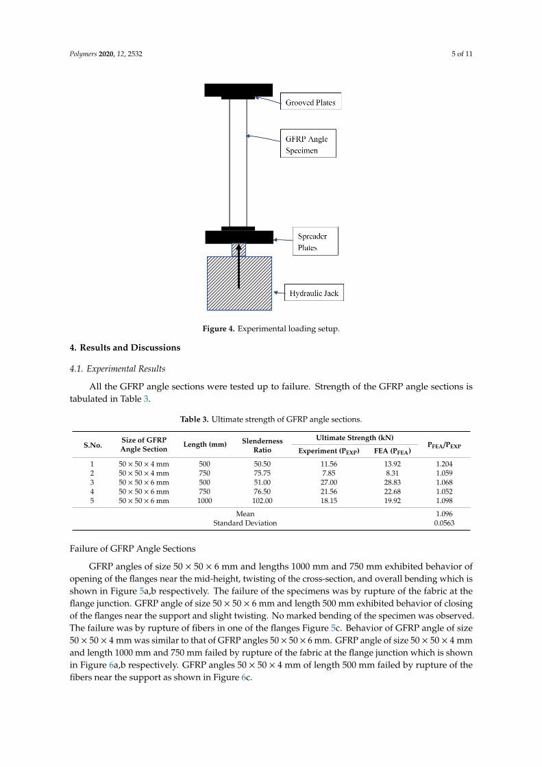
All the GFRP angle sections were tested up to failure. Strength of the GFRP angle sections is tabulated in Table 3.
Table 3. Ultimate strength of GFRP angle sections.
S.No. Size of GFRP Angle Section
Length (mm)
Slenderness Ratio
Ultimate Strength (kN) PFEA/PEXP Experiment
(PEXP) FEA
(PFEA) 1 50 × 50 × 4 mm 500 50.50 11.56 13.92 1.204 2 50 × 50 × 4 mm 750 75.75 7.85 8.31 1.059 3 50 × 50 × 6 mm 500 51.00 27.00 28.83 1.068 4 50 × 50 × 6 mm 750 76.50 21.56 22.68 1.052 5 50 × 50 × 6 mm 1000 102.00 18.15 19.92 1.098
Mean 1.096 Standard Deviation 0.0563
Failure of GFRP Angle Sections
GFRP angles of size 50 × 50 × 6 mm and lengths 1000 mm and 750 mm exhibited behavior of opening of the flanges near the mid-height, twisting of the cross-section, and overall bending which is shown in Figure 5a,b respectively. The failure of the specimens was by rupture of the fabric at the flange junction. GFRP angle of size 50 × 50 × 6 mm and length 500 mm exhibited behavior of closing of the flanges near the support and slight twisting. No marked bending of the specimen was observed. The failure was by rupture of fibers in one of the flanges Figure 5c. Behavior of GFRP angle of size 50 × 50 × 4 mm was similar to that of GFRP angles 50 × 50 × 6 mm. GFRP angle of size 50 × 50 × 4 mm and length 1000 mm and 750 mm failed by rupture of the fabric at the flange junction which is shown in Figure 6a,b respectively. GFRP angles 50 × 50 × 4 mm of length 500 mm failed by rupture of the fibers near the support as shown in Figure 6c.
Figure 4. Experimental loading setup.
4. Results and Discussions
4.1. Experimental Results
All the GFRP angle sections were tested up to failure. Strength of the GFRP angle sections istabulated in Table 3.
Table 3. Ultimate strength of GFRP angle sections.
S.No.Size of GFRPAngle Section
Length (mm) SlendernessRatio
Ultimate Strength (kN)PFEA/PEXP
Experiment (PEXP) FEA (PFEA)
1 50 × 50 × 4 mm 500 50.50 11.56 13.92 1.2042 50 × 50 × 4 mm 750 75.75 7.85 8.31 1.0593 50 × 50 × 6 mm 500 51.00 27.00 28.83 1.0684 50 × 50 × 6 mm 750 76.50 21.56 22.68 1.0525 50 × 50 × 6 mm 1000 102.00 18.15 19.92 1.098
Mean 1.096Standard Deviation 0.0563
Failure of GFRP Angle Sections
GFRP angles of size 50 × 50 × 6 mm and lengths 1000 mm and 750 mm exhibited behavior ofopening of the flanges near the mid-height, twisting of the cross-section, and overall bending which isshown in Figure 5a,b respectively. The failure of the specimens was by rupture of the fabric at theflange junction. GFRP angle of size 50 × 50 × 6 mm and length 500 mm exhibited behavior of closingof the flanges near the support and slight twisting. No marked bending of the specimen was observed.The failure was by rupture of fibers in one of the flanges Figure 5c. Behavior of GFRP angle of size50 × 50 × 4 mm was similar to that of GFRP angles 50 × 50 × 6 mm. GFRP angle of size 50 × 50 × 4 mmand length 1000 mm and 750 mm failed by rupture of the fabric at the flange junction which is shownin Figure 6a,b respectively. GFRP angles 50 × 50 × 4 mm of length 500 mm failed by rupture of thefibers near the support as shown in Figure 6c.

Polymers 2020, 12, 2532 6 of 11Polymers 2020, 12, x FOR PEER REVIEW 6 of 11
(a) Length = 1 m (b) Length = 0.75 m (c) Length = 0.5 m
Figure 5. Buckling behavior of GFRP angle sections 50 mm × 50 mm × 6 mm.
(a) Length = 1 m (b) Length = 0.75 m (c) Length = 0.5 m
Figure 6. Buckling behavior of GFRP angle sections 50 mm × 50 mm × 4 mm.
Figure 5. Buckling behavior of GFRP angle sections 50 mm × 50 mm × 6 mm.
Polymers 2020, 12, x FOR PEER REVIEW 6 of 11
(a) Length = 1 m (b) Length = 0.75 m (c) Length = 0.5 m
Figure 5. Buckling behavior of GFRP angle sections 50 mm × 50 mm × 6 mm.
(a) Length = 1 m (b) Length = 0.75 m (c) Length = 0.5 m
Figure 6. Buckling behavior of GFRP angle sections 50 mm × 50 mm × 4 mm. Figure 6. Buckling behavior of GFRP angle sections 50 mm × 50 mm × 4 mm.

Polymers 2020, 12, 2532 7 of 11
Specimens failed by rupture of GFRP and no marked delamination were observed. All specimensgave warning before failure in the form of noise. The failed specimens returned back to their originalgeometry on removal of load.
It is observed that the though the modes of failure is similar for sections 50 mm × 50 mm × 6 mm(b/t = 8.33) and 50 mm × 50 mm × 4 mm (b/t = 12.5), the ultimate strength is greatly reduced.Ultimate load reduces by about 60% when the b/t ratio is increased from 8.33 to 12.5.
4.2. Finite Element Analysis
The tested GFRP angle sections were modelled in ANSYS. A linear elastic orthotropic constitutivelaw has been adopted for the pultruded FRP material. The material properties based on tensile test andbased on properties provided by the manufacturer were input to the model. “SHELL181” quadrilateralelement was used to model the GFRP angle sections. “SHELL 181” is capable of large rotation capabilities.Automatic mapped meshing was applied to mesh the geometry. Simply supported boundary conditionswere ensured at the extremity by restraining the translational motions. The predominant mode offailure observed during experimental studies was buckling. Hence, buckling analysis using blockLanczos algorithm in ANSYS software was the focus of the simulation. Failure criteria were not adoptedin the analysis, in order to give importance to the study of global aspects of the member behavior.
The critical buckling loads and associated mode shapes were obtained from linear bucklinganalysis. A comparison of the buckling load and buckling pattern with that of the experimentalresults were made. Table 3 shows the comparison of buckling loads between finite element analysisand experiments. It was observed that the FE results vary from the experimental results by 5–6%.Figure 7 shows the comparison of buckling pattern between finite element analysis and experimentsfor slenderness ratios 50 and 100. It is observed that the numerical results based on Finite ElementAnalysis (FEA) are in good agreement with the experimental results.
Polymers 2020, 12, x FOR PEER REVIEW 7 of 11
Specimens failed by rupture of GFRP and no marked delamination were observed. All specimens gave warning before failure in the form of noise. The failed specimens returned back to their original geometry on removal of load.
It is observed that the though the modes of failure is similar for sections 50 mm × 50 mm × 6 mm (b/t = 8.33) and 50 mm × 50 mm × 4 mm (b/t = 12.5), the ultimate strength is greatly reduced. Ultimate load reduces by about 60% when the b/t ratio is increased from 8.33 to 12.5.
4.2. Finite Element Analysis
The tested GFRP angle sections were modelled in ANSYS. A linear elastic orthotropic constitutive law has been adopted for the pultruded FRP material. The material properties based on tensile test and based on properties provided by the manufacturer were input to the model. “SHELL181” quadrilateral element was used to model the GFRP angle sections. “SHELL 181” is capable of large rotation capabilities. Automatic mapped meshing was applied to mesh the geometry. Simply supported boundary conditions were ensured at the extremity by restraining the translational motions. The predominant mode of failure observed during experimental studies was buckling. Hence, buckling analysis using block Lanczos algorithm in ANSYS software was the focus of the simulation. Failure criteria were not adopted in the analysis, in order to give importance to the study of global aspects of the member behavior.
The critical buckling loads and associated mode shapes were obtained from linear buckling analysis. A comparison of the buckling load and buckling pattern with that of the experimental results were made. Table 3 shows the comparison of buckling loads between finite element analysis and experiments. It was observed that the FE results vary from the experimental results by 5–6%. Figure 7 shows the comparison of buckling pattern between finite element analysis and experiments for slenderness ratios 50 and 100. It is observed that the numerical results based on Finite Element Analysis (FEA) are in good agreement with the experimental results.
(a) Slenderness ratio = 100 (b) Slenderness ratio = 50
Figure 7. Buckling pattern—Experiment and Finite Element Analysis (FEA).
Figure 7. Buckling pattern—Experiment and Finite Element Analysis (FEA).

Polymers 2020, 12, 2532 8 of 11
4.3. Effect of Width-To-Thickness Ratio
It was observed from the experimental study that the thickness of the section and length of themember influences the buckling load. Hence, a parametric study is done varying the width to thicknessratio and slenderness ratio of the angle section.
The width of the section was kept constant and the thickness of the section was varied from 3 mmto 10 mm corresponding to width-to-thickness ratio (b/t) of 16.67 to 5 [Table 4]. The length of the sectionwas also varied from 500 mm to 1000 mm corresponding to the slenderness ratios of about 50 to 100.
Table 4. Size of angle sections considered for parametric study.
Size of the GFRP AngleSection (mm)
Width-To-ThicknessRatio (b/t)
Area of Cross-Section(mm2)
Least Radius ofGyration (mm)
50 × 50 × 3 16.7 291 9.9550 × 50 × 4 12.5 384 9.8850 × 50 × 5 10.0 475 9.8350 × 50 × 6 8.3 564 9.7950 × 50 × 7 7.1 651 9.7650 × 50 × 8 6.3 736 9.7450 × 50 × 9 5.6 819 9.73
50 × 50 × 10 5.0 900 9.73
Figure 8 shows the variation of buckling load with slenderness ratio for various width-to-thicknessratio. It is observed from Figure 8 that the buckling load decreases with increase in slenderness ratio.The rate of decrease of buckling load increases with the decrease in width-to-thickness ratio (b/t) ratio.
Polymers 2020, 12, x FOR PEER REVIEW 8 of 11
4.3. Effect of Width-To-Thickness Ratio
It was observed from the experimental study that the thickness of the section and length of the member influences the buckling load. Hence, a parametric study is done varying the width to thickness ratio and slenderness ratio of the angle section.
The width of the section was kept constant and the thickness of the section was varied from 3 mm to 10 mm corresponding to width-to-thickness ratio (b/t) of 16.67 to 5 [Table 4]. The length of the section was also varied from 500 mm to 1000 mm corresponding to the slenderness ratios of about 50 to 100.
Table 4. Size of angle sections considered for parametric study.
Size of the GFRP Angle Section (mm)
Width-To-Thickness Ratio (b/t)
Area of Cross-Section (mm2)
Least Radius of Gyration (mm)
50 × 50 × 3 16.7 291 9.95 50 × 50 × 4 12.5 384 9.88 50 × 50 × 5 10.0 475 9.83 50 × 50 × 6 8.3 564 9.79 50 × 50 × 7 7.1 651 9.76 50 × 50 × 8 6.3 736 9.74 50 × 50 × 9 5.6 819 9.73 50 × 50 × 10 5.0 900 9.73
Figure 8 shows the variation of buckling load with slenderness ratio for various width-to-thickness ratio. It is observed from Figure 8 that the buckling load decreases with increase in slenderness ratio. The rate of decrease of buckling load increases with the decrease in width-to-thickness ratio (b/t) ratio.
The stress at buckling load was calculated from the buckling load and the variation of stress with slenderness ratio for various width-to-thickness ratio is plotted in Figure 9. It is observed that the buckling load reduces to up to 10% when the width-to-thickness (b/t) varies from 5 to 16.7. Figure 10 shows the variation of buckling load with width-to-thickness ratio for various slenderness ratios. It is observed that beyond a width-to-thickness ratio of 10, the buckling load of the section is independent of the slenderness ratio.
Figure 8. Effect of slenderness ratio and width-to-thickness ratio on buckling load. Figure 8. Effect of slenderness ratio and width-to-thickness ratio on buckling load.
The stress at buckling load was calculated from the buckling load and the variation of stress withslenderness ratio for various width-to-thickness ratio is plotted in Figure 9. It is observed that thebuckling load reduces to up to 10% when the width-to-thickness (b/t) varies from 5 to 16.7. Figure 10shows the variation of buckling load with width-to-thickness ratio for various slenderness ratios. It isobserved that beyond a width-to-thickness ratio of 10, the buckling load of the section is independentof the slenderness ratio.

Polymers 2020, 12, 2532 9 of 11Polymers 2020, 12, x FOR PEER REVIEW 9 of 11
Figure 9. Variation of stress at buckling load with slenderness ratio and width-to-thickness ratio.
Figure 10. Effect of width-to-thickness ratio on buckling load.
5. Conclusions
In this paper, an experimental and numerical study is carried out on the buckling response of GFRP angle sections of varying thickness and length to bring out the influence of these geometric parameters on the buckling strength and buckling mode. The study involved testing of GFRP angle columns under concentric axial load and development of Finite Element Model (FEM) using ANSYS.
Based on the study on GFRP angle sections under concentric axial compression, the following conclusions are made:
• Specimens of length 750 mm and 1000 mm buckled in overall flexural buckling mode with opening of the flanges. The failure was by rupture of fibers at the junction of the two flanges at mid height.
Figure 9. Variation of stress at buckling load with slenderness ratio and width-to-thickness ratio.
Polymers 2020, 12, x FOR PEER REVIEW 9 of 11
Figure 9. Variation of stress at buckling load with slenderness ratio and width-to-thickness ratio.
Figure 10. Effect of width-to-thickness ratio on buckling load.
5. Conclusions
In this paper, an experimental and numerical study is carried out on the buckling response of GFRP angle sections of varying thickness and length to bring out the influence of these geometric parameters on the buckling strength and buckling mode. The study involved testing of GFRP angle columns under concentric axial load and development of Finite Element Model (FEM) using ANSYS.
Based on the study on GFRP angle sections under concentric axial compression, the following conclusions are made:
• Specimens of length 750 mm and 1000 mm buckled in overall flexural buckling mode with opening of the flanges. The failure was by rupture of fibers at the junction of the two flanges at mid height.
Figure 10. Effect of width-to-thickness ratio on buckling load.
5. Conclusions
In this paper, an experimental and numerical study is carried out on the buckling response ofGFRP angle sections of varying thickness and length to bring out the influence of these geometricparameters on the buckling strength and buckling mode. The study involved testing of GFRP anglecolumns under concentric axial load and development of Finite Element Model (FEM) using ANSYS.
Based on the study on GFRP angle sections under concentric axial compression, the followingconclusions are made:
• Specimens of length 750 mm and 1000 mm buckled in overall flexural buckling mode with openingof the flanges. The failure was by rupture of fibers at the junction of the two flanges at mid height.

Polymers 2020, 12, 2532 10 of 11
• Specimens of length 500 mm failed by torsional buckling with closing of the flanges near theloading end. The failure was by rupture of fibers in one of the flanges.
• Based on experimental study, it is observed that an increase in b/t ratio from 8.3 to 12.5 decreasesthe load carrying capacity by about 60%.
• Developed finite element model compares well with the experimental study.• Based on the parametric study, it is observed that the buckling strength decreases with increase in
slenderness ratio and width-to-thickness ratio.• The influence of width-to-thickness ratio is more at lower slenderness ratios. However the study
was limited to GFRP angles in the slenderness range of 50 to 100. Future studies can includeslenderness ratios beyond these values to have a better understanding of the behavior.
Author Contributions: Conceptualization, R.S.S. and R.S.; methodology, R.S.S. and R.S.; software, R.S.; validation,R.S.; formal analysis, R.S.S. and R.S.; investigation, R.S.; resources, R.S.S. and R.S.; data curation, R.S.S. and R.S.;writing—original draft preparation, R.S. and R.S.S.; writing—review and editing, R.S.S.; visualization, R.S.S.All authors have read and agreed to the published version of the manuscript.
Funding: This research received no external funding.
Acknowledgments: The authors gratefully acknowledge the Department of Civil Engineering, Anna Universityfor providing the laboratory facilities to conduct the experiments. Axial load test on GFRP angles wereconducted at Structural Dynamics Laboratory, Division of Structural Engineering, Department of Civil Engineering,Anna University, Chennai, India.
Conflicts of Interest: The authors declare no conflict of interest.
References
1. Godat, A.; Légeron, F.; Gagné, V.; Marmion, B. Use of FRP pultruded members for electricity transmissiontowers. Compos. Struct. 2013, 105, 408–421. [CrossRef]
2. Prasad Rao, N.; Rokade, R.P.; Balagopal, R. Failure investigation of GFRP communication towers.Eng. Fail. Anal. 2017, 79, 397–407. [CrossRef]
3. Zureick, A.; Steffen, R. Behavior and design of concentrically loaded pultruded angle struts. J. Struct. Eng.N. Y. 2000, 126, 406–416. [CrossRef]
4. Cardoso, D.C.T.; Togashi, B.S. Experimental investigation on the flexural-torsional buckling behavior ofpultruded GFRP angle columns. Thin-Walled Struct. 2018, 125, 269–280. [CrossRef]
5. Barbero, E.; Tomblin, J. Euler buckling of thin-walled composite columns. Thin-Walled Struct. 1993,17, 237–258. [CrossRef]
6. Barbero, E.; Tomblin, J. A phenomenological design equation for FRP columns with interaction betweenlocal and global buckling. Thin-Walled Struct. 1994, 18, 117–131. [CrossRef]
7. Pecce, M.; Cosenza, E. Local buckling curves for the design of FRP profiles. Thin-Walled Struct. 2000,37, 207–222. [CrossRef]
8. Mottram, J.T. Determination of critical load for flange buckling in concentrically loaded pultruded columns.Compos. Part B Eng. 2004, 35, 35–47. [CrossRef]
9. Ragheb, W.F. Local buckling analysis of pultruded FRP structural shapes subjected to eccentric compression.Thin-Walled Struct. 2010, 48, 709–717. [CrossRef]
10. Nunes, F.; Correia, M.; Correia, J.R.; Silvestre, N.; Moreira, A. Experimental and numerical study on thestructural behavior of eccentrically loaded GFRP columns. Thin-Walled Struct. 2013, 72, 175–187. [CrossRef]
11. Cardoso, D.C.T.; Harries, K.A.; Batista, E.D.M. Compressive local buckling of pultruded GFRP I-sections:Development and numerical/experimental evaluation of an explicit equation. J. Compos. Constr. 2015, 19.[CrossRef]
12. Nunes, F.; Correia, J.R.; Silvestre, N. Structural behaviour of hybrid FRP pultruded columns. Part 1:Experimental study. Compos. Struct. 2016, 139, 291–303. [CrossRef]
13. Liu, T.Q.; Vieira, J.D.; Harries, K.A. Lateral torsional buckling and section distortion of pultruded GFRPI-sections subject to flexure. Compos. Struct. 2019, 225, 111151. [CrossRef]
14. Shan, L.; Qiao, P. Flexural-torsional buckling of fiber-reinforced plastic composite open channel beams.Compos. Struct. 2005, 68, 211–224. [CrossRef]
Polymers 2020, 12, 2532 11 of 11
15. Doan, Q.H.; Thai, D. materials A Numerical Study of the Effect of Component Dimensions on the CriticalBuckling Load of a GFRP Composite Strut under Uniaxial Compression. Materials 2020, 13, 931. [CrossRef][PubMed]
16. Hashem, Z.A.; Yuan, R.L. Short vs. long column behavior of pultruded glass-fiber reinforced polymercomposites. Constr. Build. Mater. 2001, 15, 369–378. [CrossRef]
17. Cardoso, D.C.T.; Harries, K.A.; Batista, E.D.M. Compressive strength equation for GFRP square tube columns.Compos. Part B Eng. 2014, 59, 1–11. [CrossRef]
18. Puente, I.; Insausti, A.; Azkune, M. Buckling of GFRP columns: An empirical approach to design.J. Compos. Constr. 2006, 10, 529–537. [CrossRef]
19. Laudiero, F.; Minghini, F.; Tullini, N. Buckling and postbuckling finite-element analysis of pultruded FRPprofiles under pure compression. J. Compos. Constr. 2014, 18, 04013026. [CrossRef]
20. Cintra, G.G.; Cardoso, D.C.T.; Vieira, J.D. Parameters affecting local buckling response of pultruded GFRPI-columns: Experimental and numerical investigation. Compos. Struct. 2019, 222, 110897. [CrossRef]
21. Selvaraj, M.; Kulkarni, S.M.; Rameshbabu, R. Performance Analysis of a Overhead Power Transmission LineTower Using Polymer Composite Material. Procedia Mater. Sci. 2014, 5, 1340–1348. [CrossRef]
22. Selvaraj, M.; Kulkarni, S.M.; Babu, R.R. Structural evaluation of FRP Pultruded Sections in overheadtransmission line Towers. Int. J. Civ. Struct. Eng. 2012, 2, 943–949. [CrossRef]
23. Balagopal, R.; Prasad Rao, N.; Rokade, R.P. Investigation on Buckling Behaviour of GFRP Angle Sectionswith Bolted Connections in Lattice Towers. J. Inst. Eng. Ser. A 2020, 101, 327–342. [CrossRef]
Publisher’s Note: MDPI stays neutral with regard to jurisdictional claims in published maps and institutionalaffiliations.
© 2020 by the authors. Licensee MDPI, Basel, Switzerland. This article is an open accessarticle distributed under the terms and conditions of the Creative Commons Attribution(CC BY) license (http://creativecommons.org/licenses/by/4.0/).


![Buckling Behavior of 3D Randomly Oriented CNT Reinforced … · 2015. 12. 4. · reinforced composites [2] ... Increased use of nanocomposite in various structural applications necessitates](https://img.dokumen.tips/doc/110x75/5ff8f1917772ef0e55181237/buckling-behavior-of-3d-randomly-oriented-cnt-reinforced-2015-12-4-reinforced.jpg)