Embed Size (px)
Citation preview

White Paper
IPv6 Address Planning:
Guidelines for IPv6 address
allocation
by Timothy Rooney
Product management director
BT Diamond IP

IPv6 Address Planning
BT Diamond IP Whitepaper • 1
1 Introduction
IP address planning is certainly among the critical functions required within the overall process of
planning and executing an IPv6 deployment project. After all, one needs IPv6 address space in order to
implement IPv6 and current IPv4 space must be managed in conjunction with the addition of IPv6 space.
But the overall IPv6 deployment process requires not only IPv6 address space but an assurance that
network and computing infrastructure is capable of processing and supporting IPv6 address space.
At a high level, the deployment process generally requires a computing and networking assessment,
which entails the validation of IPv6 support for your network infrastructure, devices, and applications.
Such validation starts with an accurate inventory of said infrastructure, devices and applications. If you
already maintain up-to-date network documentation including this information, you have already
completed the first step. Otherwise, various forms of discovery may be required to identify and catalog
these elements of your network. While you’re performing device and application discovery, it’s a good
idea to also discover and document your current IPv4 address space as well which will come in handy
later.
With an itemized network infrastructure in hand, the next step in planning your deployment consists of
identifying IPv6 capability. This step may rely on respective vendor statements of compatibility or
support at least initially, but ultimately will require testing prior to production rollout. For each network
and computing component, you’ll need to validate IPv6 capability or determine mitigation steps
required to bring the current state of a component to IPv6 capability. Such mitigation may entail a
software upgrade, replacement or supplementation, e.g., in the case of supplementing DHCPv4 servers
with DHCPv6 servers.
Upon completion of your review and assessment of your computing inventory, you’ll end up with two
lists: one consisting of your IPv6-ready components and the other of your IPv6 “to do” list itemizing
those elements requiring upgrade, replacement or supplementation. IPv6 has been around for quite
some time, at least as a set of specifications, so vendors have had time to implement IPv6 support and
hopefully most if not all of your components are IPv6 capable today. If not, you may have to prioritize
your “to do” list based on the magnitude of the list along with your available resources. This may require
scoping of your deployment to a finite region of your network, which is probably a good idea in any case
to deploy initially within a controlled scope.
You’ll then be able to create a project plan based on your scope and “to do” list, along with lab testing to
validate IPv6 capability and to prepare operationally prior to production. Your plan also needs to include
your strategy for allocating your IPv6 address space and for managing your IPv4-IPv6 network. Plan to
obtain an IPv6 address block from your Internet Service Provider (ISP) or Regional Internet Registry
(RIR). With an IPv6 address block in hand, how should you carve this up to support your IPv6
deployment? Certainly, you’ll need to allocate IPv6 space in a manner that provides IPv6 address
availability to those infrastructure and computing devices requiring IPv6 communications. This is where
your IPv4 address space documentation or discovery can help in identifying IP address capacity
requirements. But before you carve up your IPv6 address space in a manner analogous to your IPv4
space, consider the many other implications of IP address allocation and network management,
discussed next.

IPv6 Address Planning
BT Diamond IP Whitepaper • 2
2 Addressing impacts on managing your network
Besides assessing the ability of your current IPv4 network devices and applications to support IPv6,
you’ll also need to think about how you will manage a dual protocol IPv4-IPv6 network. Management
includes not only monitoring, fault detection and resolution, but also provisioning, performance
management, and security. For each management system in use within your network for these
respective purposes, consider its IPv6 abilities. You may need to upgrade, replace or supplement your
management and security systems as well. But your IP address plan also plays a critical role in the
ongoing manageability of your network.
2.1 Routing performance
Besides analyzing and forwarding IP packets across your network, routers also communicate among
themselves regarding reachability of destination networks and nodes. Use of a routing protocol like
Open Shortest Path First (OSPF) or Border Gateway Protocol (BGP) enables routers within a given
network to identify optimal routes for IP packets across your network and to reroute around congestion
or failure points.
Thus routers need to communicate frequently to identify and reroute around network issues. In each
such communication, routers generally communicate reachability metrics for each network to provide
information to peer routers for making routing decisions. If your network is modestly sized with less
than a few hundred subnets, routing performance may be of minor concern. However for larger
networks, the volume of “routes” communicated in each routing protocol exchange literally reduces the
router cycles available to process user IP packets. In addition, processing of IP packets may require more
cycles if routing tables updated by these routing protocols are correspondingly large. For such networks,
your IP address plan can help improve routing efficiency by supporting hierarchical allocation.
Many modest to large networks are architected with a tradition three layer model, with an access layer
comprising routers directly serving end users, which feed into routers within a regional layer which
handle primarily intra-regional routing with escalation to routers within a core layer, which interconnect
Figure 1 Example router topology

IPv6 Address Planning
BT Diamond IP Whitepaper • 3
regions. A hierarchical address plan allocates large blocks for each core router. Each regional router is
allocated space from its respective core address block. Each access router is in turn allocated space from
its respective access router.
Consider the example network of Figure 1. In this example router Rc is a core router. It and its core peer
routers each serve a number of subtending regional routers. In Figure 1, Rc supports regional routers Rr1
and Rr2. Each regional router supports one or more access routers as illustrated in the figure with
regional router Rr1 serving access routers Ra11, Ra12 and Ra13. Let’s say my ISP allocated address block
2001:db8:1a::/48 for my network. Under a hierarchical allocation model, I would allocate a large block
to each core router, say block 2001:db8:1a:1000::/52 for router Rc. This block then serves as the pool for
subtending access routers. For example, I may allocate 2001:db8:1a:1000::/56 and
2001:db8:1a:1100::/56 to routers Rr1 and Rr2 respectively. In turn, each regional router block is further
allocated for subtending access routers. I may allocate for example a /64 for each access router
interface, each of which supports a subnet for end user devices. I can allocate router Ra21 the network
2001:db8:1a:1110::/60, from which I can assign subnet addresses for router interfaces, e.g.,
2001:db8:1a:1110::/64, 2001:db8:1a:1111::/64, 2001:db8:1a:1112::/64, etc.
This hierarchical allocation model enables my core routers to communicate just one route each, in this
case of size /52, in its routing updates. Each of my regional routers can likewise communicate a single
route, a /56 sized network in its routing update. And finally each access router communicates
reachability to its /60 network. As you can see, the “roll up” of address space hierarchically leads to
optimal efficiency in routing tables and routing protocol communications.
2.2 Router policies based on IP addresses
Routers leverage routing tables stored in memory to make routing decisions. These routing tables are
updated by frequent routing protocol communications with peer routers. Routers generally may also be
configured to use additional information to make routing decisions, particularly based on information in
the header of each IP packet it processes, including source and destination IP addresses. The router may
drop packets from certain source IP addresses, may prioritize packets of with a given destination
address or other header parameter values, or otherwise treat packets based on header parameter
values.
For example, some organizations allocate separate address space to be assigned to voice over IP (VoIP)
devices as contrasted to data devices. An IP packet incoming to a router with a source IP address
assigned from the VoIP space should be treated in accordance with the VoIP policy. Similarly, a packet
with source IP address from the data space should be treated as configured for the data policy.
In this case of configuring routing policy based on the source or destination IP address, your IP
addressing plan will directly impact the simplicity or complexity of defining such policies. Building on our
network example, let’s decide to allocate each access router’s /64 subnet in accordance with an “even-
dd” policy where an “even” address is a VoIP address and an “odd” address is a data address. For
example on “interface 1” for router Ra21, I will allocate 2001:db8:1a:1110::/64 for VoIP users on this
interface and 2001:db8:1a:1111::/64 for data users on this interface. For “interface 2” on router Ra21, I
can allocate 2001:db8:1a:1112::/64 for VoIP users on this interface and 2001:db8:1a:1113::/64 for data
users on this interface, and so on. Simple enough. The issue now becomes one of ongoing management
and inevitable policy changes required over time. If I need to change a router parameter for how VoIP
packets are treated, I will need to create a policy entry for each “even” subnet in my network in the
worst case! If you have hundreds of routers and/or interfaces, you can imagine the potential complexity.

IPv6 Address Planning
BT Diamond IP Whitepaper • 4
2.3 Security functions
Much like the definition of IP address based routing treatment policies, security policies can be scoped
based on IP addresses. Filtering of packets based on source or destination IP addresses and perhaps
other header information such as port number is common practice. Hence your IP address plan will have
an impact on the day-to-day manageability of configuring and updating security policies.
Configuring access control lists (ACLs) based on IP addresses can be simplified if the address plan is
defined such that ACLs can be defined with just a few entries in the ACL configuration of the router,
firewall, DNS server or device in question. Ongoing security operations may require the need to redirect
traffic, isolate or quarantine a site known to have an active virus or bot, or to “zoom in” on a particular
traffic flow for troubleshooting or analysis. In our example, each access router was allocated a /60 block.
If each access router represents a site, this allocation strategy facilitates the quarantining of a given site
from a security perspective by blocking traffic into the regional routers from the site’s /60 network.
3 Goals of an IPv6 address plan
As we’ve demonstrated, your IP address plan is vital not only to making sure network devices are
uniquely addressed, but also to facilitating ongoing management of your network. We’ll walk through
specific examples illustrating these concepts in more detail, but first let’s review the goals of an IP
address plan.
1) Provide address capacity
The fundamental goal of an IP address plan is to provide IP addresses to infrastructure and end
user devices. Without an IP address, a device by definition cannot communicate on an IP
network. Of course you may want to control which devices obtain IP addresses and also
structure your IP address space to streamline routing performance.
2) Enable end nodes to communicate (or not)
Not every device obtaining an IP address on your network should necessarily have capability to
communicate with any other IP address on your network. Controlling access to sensitive
systems and applications is a network management necessity and is typically based on IP
addresses, e.g., controlling which source IP addresses can reach given destination IP addresses.
And in the age of bring your own device (BYOD), controlling access from end user devices could
represent an additional layer of access controls.
3) Enable Internet communications (or not)
Most enterprises enable internal users to communicate to Internet hosts, though the set of
destination hosts may also be constrained due to security or corporate policies implemented in
Internet routers. BYOD devices or visitors may be granted access only to Internet destinations.
Inbound communications from the Internet is generally controlled through the deployment of a
“demilitarized zone” (DMZ) where external facing web, email, DNS and other Internet servers
are deployed “in front of” an enterprise network gateway which constrains access from
Internet source addresses. Thus these policies are likewise dependent on the IP address plan.

IPv6 Address Planning
BT Diamond IP Whitepaper • 5
4) Enable communications via supported applications
IP networks support multi-media communications though different media impose different
traffic flow and response time requirements. Voice communications generally require low
latency though occasional intermittent packet drops are tolerable; meanwhile, data
communications are more tolerant to higher latency but less so to packet drops in general,
though this also depends on the particular data application in question.
Satisfying media-specific communications requirements generally involves configuration of
routers to provide application specific treatment. And in many cases, the router is configured
to recognize a given application for treatment based on the source and/or destination IP
addresses in each IP packet it processes.
5) Facilitate visual mapping of IPv6 address to location, application, node,
etc.
If you’ve been managing your IPv4 network for a while, you can probably classify an IPv4
address by sight with respect to its respective location, application or even node type (router,
switch, server, etc.). A well-structured IP address plan promotes this ability to visually identify
node properties from its IP address, as this can help improve manageability and reduce
troubleshooting time.
While it may seem simple to map the value of up to four decimal numbers within a dotted-
decimal IPv4 address to a given property, mapping a much lengthier hexadecimal IPv6 address
may seem intimidating. However, consider that every IP address in your network will share the
same prefix, e.g., 2001:db8:1a::/48 per our earlier example. The address prefix from your ISP or
RIR will be common on all IPv6 addresses unless you are deploying address spaces from one or
multiple ISPs or RIRs and/or unique local address (ULA, akin to private) space. And the second
half of each IPv6 address, bits 65-128, comprises the node’s interface identifier (IID). So the bits
between your prefix length and bit 64 comprise those bits that define your network blocks or
subnets.
In our example 16 bits, bits 49-64 within each 128-bit IPv6 address can be used within our
address plan to define our blocks and subnets. These sixteen bits represent four hexadecimal
digits, so as you define your plan, a goal should be to map each of these four hex digits to
significance that can be visually recognized (over time as you get comfortable with IPv6) as
relating to location, application, security, etc.
4 IPv6 address allocation hierarchy and techniques
Now that we’ve seen how your IP address plan impacts the manageability of your network and we’ve
discussed the goals you should consider when developing your IPv6 address plan, let’s delve into the
mechanics of performing IPv6 allocations. While you should apply a common allocation technique at
each layer of your allocation plan, you may apply different techniques at different levels of your address
plan hierarchy.
Recall in our example, we defined four layers, starting with a source IPv6 block of 2001:db8:1a::/48,
then allocating /52 blocks for the core, /56s for regions, /60s for access/sites and finally /64s for
subnets. We could apply the sparse technique for the core layer, best fit for regions, random for sites,
and monotonic for subnets for example.
IPv6 Address Planning
BT Diamond IP Whitepaper • 6
4.1 Monotonic allocation
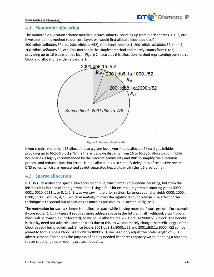
The monotonic allocation scheme merely allocates subnets, counting up from block address 0, 1, 2, etc.
If we applied this method to our core layer, we would first allocate block address 0,
2001:db8:1a:0000::/52 (i.e., 2001:db8:1a::/52), then block address 1, 2001:db8:1a:1000::/52, then 2,
2001:db8:1a:2000::/52, etc. This method is the simplest method and merely counts from 0 to f,
providing up to 16 blocks at this level. Figure 2 illustrates this allocation method representing our source
block and allocations within a pie chart.
Figure 2: Monotonic Allocation
If you require more than 16 allocations at a given level, you should allocate 2 hex digits (nibbles),
providing up to 65,536 blocks. While there is a wide disparity from 16 to 65,536, allocating on nibble
boundaries is highly recommended by the Internet community and RIRs to simplify the allocation
process and reduce allocation errors. Nibble allocations also simplify delegation of respective reverse
DNS zones, which are represented as dot-separated hex digits within the ip6.arpa domain.
4.2 Sparse allocation
RFC 3531 describes the sparse allocation technique, which entails monotonic counting, but from the
leftmost bits instead of the rightmost bits. Using a four-bit example, rightmost counting yields 0000,
0001, 0010, 0011,… or 0, 1, 2, 3,… as we saw in the prior section. Leftmost counting yields 0000, 1000,
0100, 1100,… or 0, 8, 4, c,… which essentially mirrors the rightmost count bitwise. The effect of this
technique is to spread out allocations as much as possible as illustrated in Figure 3.
The motivation for such a scheme is to allocate space while leaving room for future growth. For example
if core router 1 Rc1 in Figure 3 requires more address space in the future, in all likelihood, a contiguous
block will be available (unallocated), so we could allocate the 2001:db8:1a:9000::/52 block. The benefit
is that Rc1 need not advertise another block due to this, as we can merely change the prefix length of the
block already being advertised. Since blocks 2001:db8:1a:8000::/52 and 2001:db8:1a:9000::/52 can be
joined to form a single block, 2001:db8:1a:8000::/51, we need only adjust the prefix length of Rc1’s
advertisement. This serves the purpose of adding needed IP address capacity without adding a route to
router routing tables or routing protocol updates.

IPv6 Address Planning
BT Diamond IP Whitepaper • 7
4.3 Best-fit allocation
You may be familiar with the best-fit allocation method in trying to squeeze every IPv4 block available in
an optimal manner. Classless Inter-Domain Routing (CIDR) introduced the concept of variable sized non-
octet bounded network addressing to more precisely meet address capacity requirements while
conserving IPv4 address space.
With the vast IPv6 address space, this may not be of a concern at least today. In general, you should
keep things simple and allocate same-sized blocks at each layer of your hierarchy if possible. However,
to illustrate this technique, Figure 4 shows an example of best-fit allocation, which entails allocation of
the smallest available block to meet the demand requested. In the figure, we’ve allocated three /52’s for
three of our routers, but Rc3 requires a larger allocation, a /51 (again, nibble boundary allocations are
recommended!) and is allocated 2001:db8:1a:4000::/51.
From this state of Figure 4, if the next allocation called for a /52, the wedge between the allocations,
2001:db8:1a:3000::/52 could be allocated; if a /51 was needed, 2001:db8:1a:6000::/51, contiguous with
our already-allocated /51, could be allocated.
Figure 3: Sparse allocation

IPv6 Address Planning
BT Diamond IP Whitepaper • 8
Figure 4: Best fit allocation
4.4 Random allocation
A random allocation mechanism features randomizing the bits for the allocation layer in question. In our
example, we are allocating 4 bits to our core layer. Define a random number between 0 and 15 (f) and if
not already allocated, allocate this block address. Figure 5 illustrates an example of the random
allocation in pie chart form. For my first router Rc0, my random number was 5, for Rc1, 8 and for Rc2, 15 in
this example. The random allocation scheme may best apply to sites or subnets in order to avoid
monotonic block counting, to make it more difficult for someone to footprint or discover your IP
allocation plan from a security perspective.
Figure 5: Random allocation

IPv6 Address Planning
BT Diamond IP Whitepaper • 9
4.5 Prefix delegation
Prefix delegation is not an allocation technique per se, but it provides a mechanism to automate
allocations within the network using the DHCPv6 protocol. A router or DHCPv6 server configured with a
pool of blocks can allocate entire blocks to downstream requesting routers. A service provider desiring
to allocate /56 blocks to customers might use prefix delegation to automate this process upon
provisioning for example.
5 Allocation use cases/examples
Having now defined our allocation techniques, let’s now turn to some examples. Section 2 introduced
one example allocation scheme based primarily on mimicking routing topology. In this section, we will
review and contrast two example allocation strategies to help convey the trade-offs in defining the
order or allocation.
5.1 Case 1
Let’s start with our source IPv6 block, 2001:db8:1a::/48. We will allocate space successively for the
following layers: application, location, business unit and site.
5.1.1 Allocations
I will perform my first layer allocation by application, VoIP, video, data, wireless, etc. This will enable me
to define one routing policy across all of my routers for each application as appropriate. I have less than
16 allocations, so let’s allocate the first nibble, bits 49-52 as follows. I am also using the sparse allocation
technique to allow room for growth.
- Data: 2001:db8:1a:0000::/52
- Voice: 2001:db8:1a:8000::/52
- Video: 2001:db8:1a:4000::/52
- Wireless: 2001:db8:1a:c000::/52
- Management: 2001:db8:1a:2000::/52
My single video routing policy statement to be configured in all of my routers need only enumerate
application to packets with source IPv6 address within the 2001:db8:1a:4000::/52 block.
Next I’d like to allocate my second layer by region, taking the next nibble or four bits. These I will also
allocate sparsely. For each application block defined above, I now need to allocate by region.
Consideration our Voice block, our regions might be allocated as follows.
- Voice – Eastern region: 2001:db8:1a:8000::/56
- Voice – Northern region: 2001:db8:1a:8800::/56
- Voice – Western region: 2001:db8:1a:8400::/56
- Voice – Southern region: 2001:db8:1a:8c00::/56
I would repeat the allocation of four regions within each application block, assuming each application is
supported in each region. With 5 blocks at my top layer and 4 in the second layer, I will have made up to
20 allocations so far.

IPv6 Address Planning
BT Diamond IP Whitepaper • 10
Now I want to define a third layer, this one by business unit, and I’ll use the next nibble, bits 57-60.
Assuming each business unit requires representation in each region and for each application, I need to
add each business unit to my 20 existing allocations. So if I have five business units, that’s 100
allocations! Let’s look at the Voice - Southern region branch and add our business unit allocations
monotonically:
- Voice – Southern region – Corporate: 2001:db8:1a:8c00::/60
- Voice – Southern region – Finance: 2001:db8:1a:8c10::/60
- Voice – Southern region – Marketing: 2001:db8:1a:8c20::/60
- Voice – Southern region – Engineering: 2001:db8:1a:8c30::/60
- Voice – Southern region – Customer Support: 2001:db8:1a:8c40::/60
I have four bits remaining which I can allocate to specific subnets for each business unit with each region
for each application. For example if I have 3 subnets for my Marketing team for voice service in the
southern region, I could allocate randomly:
- Voice – Southern region – Marketing – Site 1: 2001:db8:1a:8c2a::/64
- Voice – Southern region – Marketing – Site 2: 2001:db8:1a:8c29::/64
- Voice – Southern region – Marketing – Site 3: 2001:db8:1a:8c2e::/64
5.1.2 Observations
As you may have observed as we built out our example, successively drilling down to maintain brevity,
our subnet bits, particularly bits 49-64, do provide a visual mapping to a given subnet’s application,
region, business unit and site. In our final allocation, you can see that the subnet “8c29” is for voice,
southern, marketing and site 2. If we’ve maintained uniformity in our allocations across parallel
branches, we can also readily state that subnet “403e” applies to video (first nibble, “4”), east (“0”),
engineering (“3”) and site 3 (“e”) though with a random allocation my site number may not map
analogously. But in general the visual mapping goal has been achieved, and over time, you will recognize
each by sight!
I could generally conclude that we should be able to achieve the goal of providing communications by
our supported IP-based applications, given this criterion comprised our first layer. And my routing policy
implementation and management is quite simple given one entry (IPv6 block) per application. Assuming
I’ve identified my regions and sites according to my current network reach and capacity requirements,
it’s likely I can check off the goal of providing IP address capacity. In terms of route efficiency, assuming
routers are conveyed at the region level, my core routers will require at least 20 routes in this example.
As for the goal of selectively enabling or disabling communications among nodes internally and to or
from the Internet, my achievement of this goal is not so obvious. This is where you should consider
those criteria that drive your filters and ACLs regarding constraining access by IP address. If you have a
frequent need to throttle applications by policy or set security policies by application, then this
allocation scheme achieve this with relative simplicity, with one block defined for each application
across my network. Setting such policies for a given region will require 5 statements (a given region is
defined in each of the 5 application blocks) in our example. In general setting second layer policies upon
a single nibble first layer requires up to 16 entries. Setting such policies by business unit is more
onerous, requiring setting of only 20 in our example but up to 65,536 (two nibble’s worth) of policies to
define the business unit traffic per region and per application.
IPv6 Address Planning
BT Diamond IP Whitepaper • 11
5.2 Case 2 Let’s start again with our source IPv6 block, 2001:db8:1a::/48. This time, we will allocate space
successively for the following layers: business unit, application, location, and site.
5.2.1 Allocations
Following similar logic to that discussed above, let’s allocate as follows for our top layer, business unit:
- Corporate: 2001:db8:1a:0000::/52
- Finance: 2001:db8:1a:1000::/52
- Marketing: 2001:db8:1a:2000::/52
- Engineering: 2001:db8:1a:3000::/52
- Customer Support: 2001:db8:1a:4000::/52
Our next layer is application, so considering application allocations within our Engineering block:
- Engineering - Data: 2001:db8:1a:3000::/56
- Engineering - Voice: 2001:db8:1a:3800::/56
- Engineering - Video: 2001:db8:1a:3400::/56
- Engineering - Wireless: 2001:db8:1a:3c00::/56
- Engineering - Management: 2001:db8:1a:3200::/56
We allocate by region as our third layer, so drilling into Engineering – Data, we have:
- Engineering - Data – Eastern region: 2001:db8:1a:3000::/60
- Engineering - Data – Northern region: 2001:db8:1a:3080::/60
- Engineering - Data – Western region: 2001:db8:1a:3040::/60
- Engineering - Data – Southern region: 2001:db8:1a:30c0::/60
And finally by site, considering our Engineering – Data – Northern region block:
- Engineering - Data – Northern region – Site 0: 2001:db8:1a:3080::/60
- Engineering - Data – Northern region – Site 1: 2001:db8:1a:3081::/60
- Engineering - Data – Northern region – Site 2: 2001:db8:1a:3082::/60
5.2.2 Observations
As in Case 1, our nibble based allocation has again yielded a visually discernible classification of a subnet
by business unit, application, region and site, which should generally facilitate manageability. We may
also surmise that our goals of providing for capacity and applications use have likewise been satisfied.
Our route efficiency, again assuming a route is required at the core for each regional level, has suffered
as we now have 100 unique region entries, one per application per business unit.
Regarding our routing and security policies, this case certainly simplifies setting of policies by business
unit, with one block for each. This comes at the expense of increasing the effort to institute application
based policies and further complicates regional based policies. In general, the number of policy entries

IPv6 Address Planning
BT Diamond IP Whitepaper • 12
at each level for a given criterion is calculated as the product of the number of allocations of each layer
above in the allocation hierarchy.
6 General block allocation guidelines
As you begin preparing your IPv6 address plan, keep in mind there is no “cookie-cutter” solution and
each address planner must consider several factors as illustrated above. Think about your router
topology and relative importance of constraining router table sizes. Consider the applications supported
by your network, particularly those utilizing IP-based routing treatment. Identify and prioritize your
frequent management and security processes and requirements. Review the goals we discussed earlier
and define those that are most important to you.
In terms of allocation layers and address block structure, you should consider your current IPv4
structure as a data point, not necessarily as a model. You may wish to allocate an IPv6 subnet for every
IPv4 subnet you’ve allocated, but you may be able to consolidate subnet addresses given the vast size of
a given /64 IPv6 subnet with capacity for 1.8 X 10¹⁹
addresses.
Your current IPv4 address space also provides useful information regarding IP address capacity
requirements at the host level, helping define how many addresses are required in given locations and
by application or media type. In general, it’s a good idea to baseline your IPv4 address plan as input to
the IPv6 plan, again as a data point, not necessarily as a template.
The following is a summary of key guidelines when defining your IPv6 address plan.
� Baseline your IPv4 address space in terms of documenting your IP blocks, subnets, host
assignments and DHCP pools. If you’re using an IP address management (IPAM) system, this
information should be readily available. Otherwise you may need to run network discoveries to
confirm and validate IP address allocations.
� Define all of your IPv6 address space(s) to be allocated. So far we’ve talked about public space
from your ISP or RIR and briefly mentioned unique local address (ULA) space. Also consider if
you use or plan to use any IPv4-IPv6 co-existence technologies besides dual stack including
tunneling or translation techniques, most of which have implications on IP address assignment
and formats. Your address plan should enumerate each use of IPv6 address space.
� Identify your network routing and switch infrastructure and document your network
architecture, e.g., routing layers per the discussion in section 2. Determine the level of
importance of routing table sizes in your environment. The more critical for you to keep routes
contained, the higher a router level allocation layer should be in your plan’s layers.
� Enumerate IP address based policies in use or planned for your network. This includes routing
policies, packet treatment policies, filtering, ACLs, and other IP address based configuration
parameters within your infrastructure. Determine the rate of change or urgency to enact
policies at a given level. If you plan to setup application based policies once and plan no or
minimal changes, then your application allocation should you choose to include such a layer,
may be deeper in your allocation plan. For those frequently changing policies or for potentially
urgent requirements (e.g., to quarantine a site), consider placing allocations encapsulating the
scope of these policies higher in your allocation plan.
� Define the homogeneity of your network. In our use cases, we assumed all applications were to
be available at all locations for all business units. If this is not the case, then those more
universal criteria should be higher than those more limited in scope in your allocation layers.

IPv6 Address Planning
BT Diamond IP Whitepaper • 13
� Consider administrator delegation and responsibilities, especially if defined by IP addresses, and
how frequently or urgently these are changed.
� Identify DNS configurations (zone files) recognizing that as you deploy IPv6, hosts will require
IPv6 DNS resource records (AAAA and PTR among others). That is for a dual stack
implementation a given hostname should have both A and AAAA records in the corresponding
DNS zone. If you delegate DNS responsibilities within your organization, zone administrators
may require training to properly configure DNS resource records and IPv6 reverse (ip6.arpa)
zones.
� Evaluate alternative allocation techniques, monotonic, sparse, best-fit and random, then define
your approach for each layer.
� Plan to allocate on nibble boundaries to ease the allocation process, to provide visual address
mapping and to simplify DNS configurations especially for delegated zones corresponding to
IPv6 allocations.
7 ULA considerations
Unique Local Address (ULA) space in IPv6 is analogous to private address space in IPv4. Most IP planners
have become accustomed to the common IPv4 addressing strategy of utilizing private RFC 1918 space
internally to their networks, then through the use of proxies and/or network address translators (NATs),
translate private address space to a smaller pool of public IP addresses for communication over the
Internet. As such, NAT was an effective component in extending the lifetime of IPv4 as each enterprise
demanded a smaller pool of public IPv4 addresses.
IPv6 does not suffer the scarcity issues of IPv4 and was designed to restore the endpoint-to-endpoint
communications model originally intended for the Internet Protocol. Hence use of NAT for IPv6 is highly
discouraged. While NAT functions may provide a sense of security by filtering and hiding internal
addresses, IPv6 address footprinting is much more difficult given the sheer size of IPv6 space. Privacy
extensions to stateless address autoconfiguration (SLAAC) also enable individual hosts to periodically
change their addresses to further complicate the reconnaissance process for would-be snoopers. NAT
devices also potentially interfere with end-to-end application performance and operation.
Public IPv6 addresses, otherwise known as global unicast addresses (GUAs), should be assigned to your
devices. Filtering is recommended from a security perspective but not NAT. Hence a model using ULA
internally NAT’d to public IPv6 is discouraged. Nevertheless, ULA space has utility for assignment to
devices that don’t require Internet access or for use on private, partner and VPN connections.
8 Renumbering impacts
Another goal of an IP address plan not stated above but certainly in the back of every IP planner’s mind
is to “get it right the first time,” so you don’t have to renumber your network. Renumbering of networks
is generally a difficult and time-consuming project and should be avoided if at all possible. This is one
reason I encourage you to take the time to develop your allocation plan, evaluate alternative strategies,
and to understand the trade-offs made in your final strategy. Regardless, even with the best laid plans,
unforeseen events occur and impact the network in such a way that a partial or complete renumbering
is required.
An initiative as seemingly innocuous as changing ISPs may necessitate a complete renumbering of your
network. But if you’ve done the analysis in diligently preparing your IPv6 address plan, such a change in

IPv6 Address Planning
BT Diamond IP Whitepaper • 14
IPv6 prefix may be a simple prefix substitution (assuming the same prefix length) within the address
plan, though actual device re-addressing must also ensue. The IETF recognizes renumbering to be a
difficult problem to solve as indicated in the title of RFC 5887, Renumbering Still Needs Work. This is due
to the need to update devices with hard-coded IP addresses for communications, for use within APIs and
configuration files and those used by network management and security systems as well.
Note that these steps are required for your initial IPv6 “numbering” project, so I advise you to document
your steps diligently so you can refer to them later should a renumbering become necessary. Though of
incomplete consolation, IPv6 does support new helpful features in renumbering, namely router
advertisements, SLAAC, and address lifetimes. Suffice it to say that you should think through your IPv6
address plan to derive to best possible address plan for your network, and document your process for
possible future reference.
9 Managing IPv4-IPv6 address space with IPControl™
BT Diamond IP address management solutions enable customers to manage their IPv4 and IPv6 space
together through a single pane of glass. Our IPControl™ software and Sapphire appliances streamline
the process of defining IP address space, then simply allocating space in accordance with defined
allocation policies. IPControl supports automated deployment of multiple blocks/subnets and dual stack
subnets in one step, as well as assignment of host IP addresses along with template-driven hostnames
and corresponding A/AAAA/PTR resource records. DHCPv6 address pools and prefix delegation are also
natively supported providing a fully featured IPv4-IPv6 management solution.
This paper has provided key considerations and techniques for defining your IPv6 address plan, a critical
ingredient of your IPv6 deployment plan. Take the time to carefully consider your IPv6 address structure
and strategy to develop an address plan to facilitate your IPv6 deployment and management of your
network in steady state. BT Diamond IP publishes a rich set of free IPv6 educational resources at
http://btdiamondip.com/IPv6_Resource_Center/.
About BT Diamond IP BT Diamond IP is a leading provider of software and appliance products and services that help
customers effectively manage complex IP networks. Our next-generation IP management solutions help
businesses more efficiently manage IP address space across mid-to-very large sized enterprise and
service provider networks. These products include IPControl™ for comprehensive IP address
management and Sapphire Appliances for DNS/DHCP services deployment. Our customers include
regional, national and global service providers and enterprises in all major industries.
For additional information, please visit http://btdiamondip.com or contact BT Diamond IP at 1-800- 390-
6295 in the U.S., 1-610-423-4770 worldwide or via email at [email protected].
IPControl is a trademark of BT Americas, Inc.
Copyright © 2013, BT Americas, Inc.
This is an unpublished work protected under the copyright laws.
All trademarks and registered trademarks are properties of their respective holders. All rights reserved.