Embed Size (px)
Citation preview

SPINchiller3 FREE-COOLING
Nominal cooling capacity from 260 kW to 675 kW
Technical Bulletin
FREE-COOLING high e�ciency air-cooled liquid chillerfor outdoor installation
WSAT-XSC3 FC 90.4-240.4 RANGE
BT16A004GB-04
▶ FREE-COOLING mixing section on source exchanger
▶ R-410A multiscroll technology
▶ Two independent refrigeration circuits
▶ Di�users for thermodynamic recovery fans
EXCELLENCE version
▶ Up to 45°C outdoor air temperature / Perferct for LEED

2 SPINchiller3 FREE-COOLING BT16A004GB-04
Clivet hydronic systemDesigned to provide high energy e�ciency and sustainability of the investment, the wide range of Clivet liquid chillers and heat pumps for high e�ciency air conditioning of Residential and Commercial spaces and for Industrial applications it is available with air or water source.
Specialization
Every intended use has speci�c requirements which determine the overall e�ciency. For this, the Clivet hydronic system always o�ers the best solution in every project.
• Modular range with over 8000 kW of overall capacity
• Capacity control with Screw and modular Scroll technology
• Multifunction versions
• Outdoor or indoor (ductable type) installation
Centrality of the Air Renewal Terminal and AHU complete systemFrom the Air Renewal depends the comfort in the spaces. Since it often represents the main building energetic load, it also determines the running costs of the entire system.
The hydronic terminal units are very di�used for their versatility and reliability. The Clivet range includes many versions that simplify the application in di�erents type of installation and building.
ZEPHIR3Packaged Primary Air supply system with thermodynamic energy recovery.
ELFOSpaceHigh energy e�ciency hydronic terminal units
AQXAir-conditioning unit
• Cased and uncased terminal units, from 1 to 90 kW
• Horizontal and vertical installation
• Energy-saving DC fans
• Modular air conditioning units up to 160.000 m3/h
• EUROVENT certi�cation
• Simpli�es the system, reduces the heating and cooling generators
• Puri�es the air with standard electronic �lters
• Increases the energy e�ciency and it also allows a savings of 40% on the running costs
• From –40°C to +50°C of outdoor air temperature

BT16A004GB-04 SPINchiller3 FREE-COOLING 3
SPINchiller3: modular scroll technology for every applicationSPINchiller3 is the new generation of Clivet liquid chillers and heat pump with modular scroll technology. Thanks to its high seasonal e�ciency and range versatility, it represents the ideal solution for di�erent types of installation.
WSAT-XSC3
Air cooled water chiller
• EXCELLENCE high e�ciency version and PREMIUM compact version
• Operating with 52°C of outdoor air temperature
• Total / partial recovery of the condensing heat
• Eurovent certi�cation
WSAT-XSC3 FREE-COOLING
Air cooled water chiller with FREE-COOLING
• Direct FREE-COOLING
• Indirect FREE-COOLING (No-Glycol)
WSAN-XSC3
Air coole heat pump
• EXCELLENCE high e�ciency version
• Eurovent certi�cation
WSAN-XSC3 Multifunction
Air cooled heat/cool heat pump with simultaneous operating
• EXCELLENCE high e�ciency version
• 4-pipe system
• 2-pipe system and total condensing heat recovery
Dedicated series separately documentated
Dedicated series separately documentated
Dedicated series separately documentated

4 SPINchiller3 FREE-COOLING BT16A004GB-04
Cost or reliability?
The dilemma of modern system engineering applications
Air-conditioning systems in trade centres in�uence both the starting investment and monthly management costs, for the whole of their working lives. This theme is even more relevant in residential applications with centralised systems. Furthermore, maximum working �exibility requirements should be added to that, in serving di�erent users while avoiding wasting energy and thus, money. Finally, there are several industrial applications which require hot or chilled water as service �uid, process �uid or vector �uid for operator comfort and for conserving goods and enabling cycles to function correctly. Furthermore, in all these cases, the working reliability of the system is decisive.
High e�ciency hydronic systems
The high e�ciency hydronic systems are extremely versatile, reliable and widespread
Despite their apparently low costs, split, multi-split and VRF direct expansion systems have a lot of limits in these applications. For example, they require a separate system for primary air treatment. The pipes that contain the refrigerant cross the served rooms and therefore they are subject to restrictions and use limitations. They cannot operate in the FREE-COOLING mode, the high e�ciency and convenient mode that allows energy savings.
The hydronic systems are certainly more complete and versatile. They make it possible to adopt various types of terminals in the served environment, from fan coil units exposed or integrated in the furnishings, up to radiant or induction systems. They are also irreplaceable in the service and process industrial applications.
The main component performances, like air-cooled liquid chillers and hydronic heat pumps, are checked and certi�cated by appropriate certi�cation programs, as Eurovent.
Clivet technological evolution
Clivet chillers reduce consumption and are compact and reliable
With over twenty years of technological evolution, Clivet liquid chillers and heat pumps represent the state of the art in air-conditioning of residential, trade and industrial environments.
Their success is based on high energy e�ciency, compactness and management maintenance simplicity, with wide versatility in the choice of the most suitable model for the speci�c use.

BT16A004GB-04 SPINchiller3 FREE-COOLING 5
Perfect for LEED certi�cationThe whole EXCELLENCE range satis�es both requirements 2 (Minimum Energy Performance) and 3 (Fundamental Refrigerant Management) of Energy and Atmosphere section. They also meet Credit 4 parameters (Enhanced Refrigerant Management) allowing 2 points acquisition.
Clivet is committed in promoting the green building principles and has become a member of GBC Italia. This organization collaborates with USGBC, the U.S. nonpro�t organization that promotes worldwide the LEED system of indipendent certi�cation.
The advantages of the modular solutionIn the event of particularly large buildings requiring high capacities, it is advisable to use several units. The ECOSHARE technology developed by Clivet allows to coordinate up to 7 units in local network, in parallel with modular logic, with the following advantages:
• greater e�ciency, because the compressors are sequentially activated exploiting at most their point of operating with the lowest consumption, and the pumping units are activated only when necessary;
• greater �exibility, thanks to capability of the automatic control to follow the load;
• increased reliability, since the malfunction of one unit does not compromise the capacity supply of the other units.
Remote system managementThe unit is standard equipped with:• potential-free contact for remote on/o� control;• potential-free contacts for the compressor status display;• setting from user interface: O� / local On / serial On;• potential-free contact to remote a general alarm.
Thanks to the di�erent communication protocols available, the unit is able to exchange information with the main supervisory systems using serial connections.
FREE-COOLING always convenient For industrial or civil applications where cooling capacity required is stable in any outdoor condition and it is not e�ected by outdoor temperature, using solutions that exploit low outdoor temperatures for supplying cooling capacity for free is strongly suggested.
The new SPINchiller³ FREE-COOLING series is the answer to that, and thanks to large exchanging surfaces with an antifreeze solution drives to notable annual energy consumption savings, up to 40% in harsh climate.
Not only great winter performances thanks to FREE-COOLING but also all SPINchiller³ bene�ts and especially very high e�ciency at high outdoor temperature conditions.
During one operative year of FREE-COOLING units 70% of the time compressors are running and providing a quite important cooling capacity amount.
It is mandatory to provide a good e�ciency even when FREE-COOLING is OFF, in these conditions SPINchiller³ drives to an high saving thanks to a full load e�ciency up to 3,3.
Available with two con�gurations:
• direct FREE-COOLING (FCD): for systems with glycol;
• glycol free FREE-COOLING (FCI): for systems without glycol.
10% of savings with an higher set pointFor industrial applications, water supply could be di�erent than 7°C. With FREE-COOLING units the advantages in terms of e�ciency increasing water temperature set-point by few degrees is even more noticeable, driving to annual energy savings higher than 8% with a set point of 10°C for example, concrete economical value for this kind of applications.

6 SPINchiller3 FREE-COOLING BT16A004GB-04
SPINchiller3
Provides all Clivet technological developments for their medium capacity hydronic systems
High e�ciency Scroll compressors, high performance heat exchangers, electronic control fans, fully automatic operation: these are only some of the technologies available with SPINchiller3, in a range of models that are ideal for high capacity air conditioning systems in commercial, residential and industrial buildings.
The EXCELLENCE version stands out for its extremely high energy e�ciency under both part and full load conditions.
SPINchiller3 can also be supplied in many con�gurations equipped with the main components installed built-in.
AdvantagesHigh e�ciency all year round
SPINchiller3 reduces yearly energy consumption thanks to its high part-load e�ciency i.e., by far the most frequent condition throughout the system’s life-cycle. This way, even the value of the served building increases. The main components are manufactured on an industrial scale, with maximum manufacturing reliability and can be easily found as spare parts.
To further increase energy e�ciency in a system with several SPINchiller3 units operating on the same equipment, there is the innovative ECOSHARE feature, which automatically distributes the load and activates the necessary pumps.
System simpli�cation
All of the features are provided by Clivet already assembled and tested built-in, di�erently then other manufacturers who make numerous additional components available to be installed on site.
Compact and versatile
Suitable for any type of terminals, from fan coils to radiant systems and chilled beams, SPINchiller3 is also available in Super-silenced con�guration. Energy recovery for producing hot water free of charge, FREE-COOLING. Seasonal energy e�ciency is further increased with the DST operating logic, which maintains a constant return temperature.
Borderless multiscroll technologyWith SPINchiller3 the modular scroll compressor technology reaches the best levels of performance and versatility ever, guaranteeing competitiveness in more and more demanding applications. The top class seasonal e�ciency rewards SPINchiller3 in comparison to any other air cooled chiller technology. A comparison with three SPINchiller3 competitors such as:
• air cooled liquid chillers with magnetic bearing centrifugal compressors;
• air cooled liquid chillers with modulating capacity screw compressors;
• air cooled liquid chillers with inverter screw compressors;
shows that SPINchiller3 is the best solution, considering its seasonal e�ciency similar to the inverter screw chillers and a capital cost lower than that of centrifugal compressor chillers, even considering the capital investment pay back, that for analized technologies are always above acceptable values normally considered for system investment equal to 3 years.

BT16A004GB-04 SPINchiller3 FREE-COOLING 7
Comfort and energy saving in one solution
Maximum e�ciency is necessary with a part load
The system is required to generate maximum capacity only for a short amount of time.
Therefore, it is essential to have the maximum e�ciency under part-load conditions.
This is the only way to actually reduce overall yearly consumptions.
Part load e�ciency determines the seasonal e�ciency
Seasonal e�ciency is conventionally represented by ESEER parameters according to Eurovent and IPLV parameters according to ARI. Both give great importance to part load operation, since it is the predominant condition.
SPINchiller technology enhances part-load e�ciency
SPINchiller3 uses high e�ciency Scroll compressors.
The advantages are:
• compressors manufactured in large ranges on an industrial scale with strict quality control inspections and maximum manufacturing reliability thanks to the high production volumes;
• every refrigeration circuit uses two Scroll compressors, depending on the di�erent sizes of the unit. When two compressors are used, their sizes are di�erent in order to obtain more control steps. This way, only the necessary energy is supplied.
Doubled e�ciency
The heat exchange surface is sized for full capacity operation. Under part load condition, some compressors are automatically deactivated. Under this condition, in fact, the compressors in operation make use of a much larger surface.
This entails a reduced condensation temperature and an increased evaporation temperature. This way, the compressor capacity consumption is reduced with respect to the yield thereby increasing the overall e�ciency of the unit.
* EUROVENT (ESEER) supply times reference and ARI (IPLV) reference for seasonal e�ciency calculations.
EERc =Energy e�ciency referred to compressors
8 SPINchiller3 FREE-COOLING BT16A004GB-04
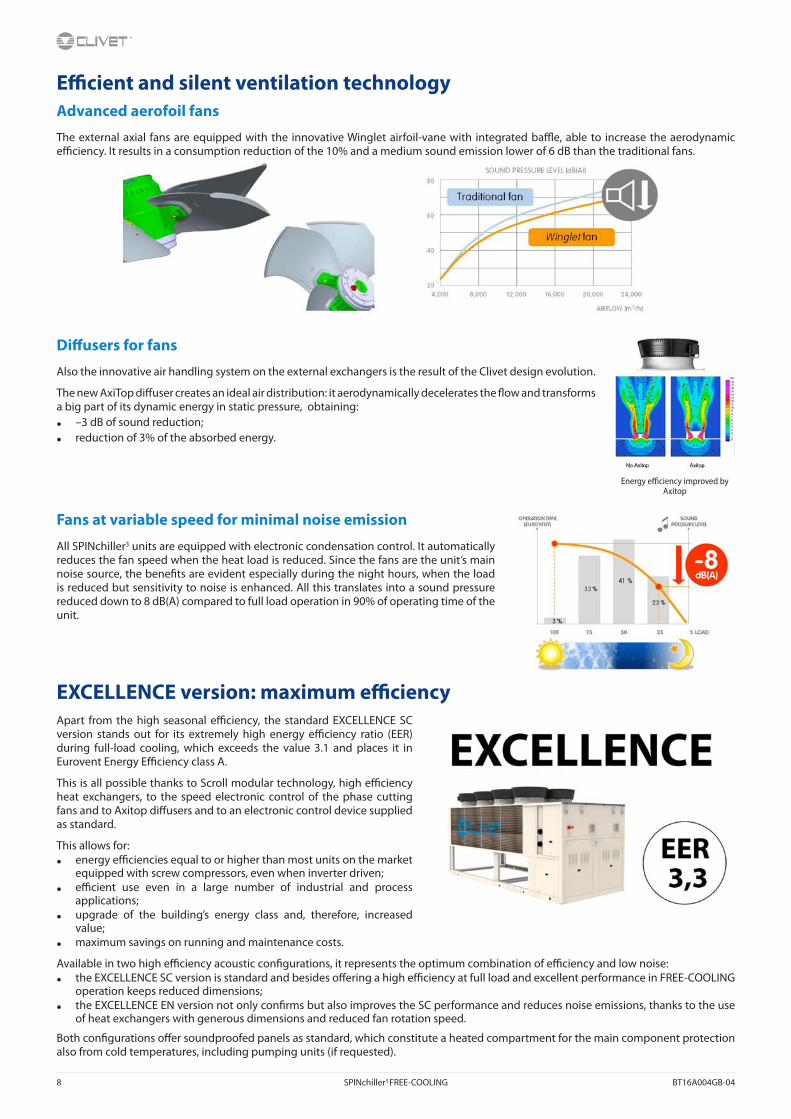
E�cient and silent ventilation technologyAdvanced aerofoil fans
The external axial fans are equipped with the innovative Winglet airfoil-vane with integrated ba�e, able to increase the aerodynamic e�ciency. It results in a consumption reduction of the 10% and a medium sound emission lower of 6 dB than the traditional fans.
Di�users for fans
Also the innovative air handling system on the external exchangers is the result of the Clivet design evolution.
The new AxiTop di�user creates an ideal air distribution: it aerodynamically decelerates the �ow and transforms a big part of its dynamic energy in static pressure, obtaining:
• –3 dB of sound reduction;
• reduction of 3% of the absorbed energy.
Fans at variable speed for minimal noise emission
All SPINchiller3 units are equipped with electronic condensation control. It automatically reduces the fan speed when the heat load is reduced. Since the fans are the unit’s main noise source, the bene�ts are evident especially during the night hours, when the load is reduced but sensitivity to noise is enhanced. All this translates into a sound pressure reduced down to 8 dB(A) compared to full load operation in 90% of operating time of the unit.
EXCELLENCE version: maximum e�ciencyApart from the high seasonal e�ciency, the standard EXCELLENCE SC version stands out for its extremely high energy e�ciency ratio (EER) during full-load cooling, which exceeds the value 3.1 and places it in Eurovent Energy E�ciency class A.
This is all possible thanks to Scroll modular technology, high e�ciency heat exchangers, to the speed electronic control of the phase cutting fans and to Axitop di�users and to an electronic control device supplied as standard.
This allows for:• energy e�ciencies equal to or higher than most units on the market
equipped with screw compressors, even when inverter driven;• e�cient use even in a large number of industrial and process
applications;• upgrade of the building’s energy class and, therefore, increased
value;• maximum savings on running and maintenance costs.
Available in two high e�ciency acoustic con�gurations, it represents the optimum combination of e�ciency and low noise:• the EXCELLENCE SC version is standard and besides o�ering a high e�ciency at full load and excellent performance in FREE-COOLING
operation keeps reduced dimensions;• the EXCELLENCE EN version not only con�rms but also improves the SC performance and reduces noise emissions, thanks to the use
of heat exchangers with generous dimensions and reduced fan rotation speed.
Both con�gurations o�er soundproofed panels as standard, which constitute a heated compartment for the main component protection also from cold temperatures, including pumping units (if requested).
Energy e�ciency improved by Axitop

BT16A004GB-04 SPINchiller3 FREE-COOLING 9
Superior �exibility and reliability
E�cient precision
Sequential activation of SPINchiller3 compressors allow:
• adapting to the load required for use, thereby ensuring added comfort;
• reducing the number of compressor start-ups, i.e., the main cause of wear;
• increasing the unit’s useful life;
• reducing repair times and costs, thanks to the modular components, their reduced dimensions and reduced cost compared to semi-hermetic compressors.
Stable and reliable operation
The electronic expansion valve (EEV) adapts rapidly and precisely to the actual load required for usage, allowing stable and reliable adjustment in comparison with mechanical thermostatic valves (TEV). This results also in a further increase in e�ciency and longer compressor life.
The overheating control allows preventing phenomena that are hazardous to the compressors, such as overtemperature and return �uids, thereby increasing even more e�ciency and durability.
Simpli�ed maintenance
Besides being e�cient, SPINchiller3 improves the system maintenance.
In fact, the malfunction of a compressor does not compromise overall operation.
Furthermore, Scroll compressors are very compact, easy to �nd and easy to handle in case of replacement.
Controlled power supply
Proper power supply ensures optimal unit operation and protects its many electrical components.
The phase monitor, standard supplied:
• controls the presence and the exact sequence of the phases;
• checks any voltage anomalies (-10%);
• automatically restarts the unit as soon as the proper power supply is restored.
Multifunction monitor, where limit values and the service schedule of Clivet’s Technical Support can be modi�ed.
THE NUMBER OF START-UPS DECREASES THEREFORE THE LIFE CYCLE INCREASES

10 SPINchiller3 FREE-COOLING BT16A004GB-04
The automatic control device coordinates resources ensuring maximum e�ciency
Operating completely automatic
The microprocessor control automatically manages operation according to the maximum e�ciency criterion and includes many safety and alarm management functions.
It also includes advanced functions, such as daily and weekly programming and automatic maximum power consumption limitation (demand limit).
Energy measuring
Monitoring energy consumption and instant power employed is the starting point to improve the system’s energy management and e�ciency. With the optional energy meter, the user displays all the information related to the unit’s electrical parameters on the interface built-in the unit or via the serial connection.
Moreover, the integration with the Demand Limit function supplied as standard allows to act on consumption levels by limiting them if they exceed the expected limit.

BT16A004GB-04 SPINchiller3 FREE-COOLING 11
Seasonal energy e�ciency is further increased with the DST operating logicSPINchiller3 is equipped with standard DST control (Dynamic Supply Temperature) control logic, which can be activated by the user.
Unlike the traditional control logic that aims at maintaining the water supply temperature constant, the DST logic aims at keeping constant the water return temperature, modifying the supply temperature dynamically according to the load. This way, evaporation temperature increases during part-load cooling, thereby increasing seasonal energy e�ciency.
The DST control allows a considerable consumption and operation costs reduction, especially in civil applications, upon veri�cation of the air treatment system’s dehumidi�cation capacity during cooling at part load.
The DST control allows considerable consumption and operation costs reduction, especially in civil applications, upon veri�cation of the air treatment system’s dehumidi�cation capacity during part-load cooling. The DST control is particularly interesting when combined with active thermodynamic fresh air systems. The direct expansion circuit allows them to operate the outdoor air treatment independently from SPINchiller², which can vary the system water supply temperature, thereby optimising energy e�ciency in the yearly cycle.
The DST control logic is as an alternative to the control logic at variable �ow-rate.
Example
The following diagram represents the various operating temperatures in the production of chilled water under various load conditions for a typical civil system consisting of:
• primary circuit with constant water �ow rate;
• secondary circuit with variable water �ow-rate according to the load (linear variability for simplicity).
The traditional control logic keeps the water supply temperature to room terminals and outdoor air treatment units constant, in order for the latter to carry out the dehumidi�cation.
The DST control logic, on the other hand, allows increasing the system water supply temperature during part-load operation, thereby increasing seasonal energy e�ciency for SPINchiller3.
The DST application must be veri�ed during the design stage according to speci�c system constraints.
Traditional control logic (system water �ow rate temperature = constant)
DST control logic (system water return temperature = constant)

12 SPINchiller3 FREE-COOLING BT16A004GB-04
SPINchiller3 technology industrialised the systemSPINchiller3 can be supplied equipped with components that are often provided separately. This allows reducing:
• design times: all accessories are made to ensure the best overall e�ciency;
• installation costs: the accessories already mechanically connected, electrically wired and individually tested are ready to be put to operate immediately;
• overall dimensions: system components are integrated with the unit, thereby reducing the technical area and increasing the area available for other uses.
Built-in inertial accumulation available
In most SPINchiller3 systems it can be installed without inertial accumulation on the system. In fact, the unit quickly adapts to the load due to modular compressors, electronic thermostatic valve and low water content plate heat exchangers. However, in the event of hydraulic distribution networks with reduced dimensions, it is important to provide the system with a hydraulic �ywheel. In such cases, inertial accumulation is available built-in, equipped with insulating coating and all the necessary safety devices. This allows eliminating installation times and costs and freeing space inside the building.
The built-in pumps are versatile, ready-for-use and reliable
The various solutions available are:
• HYDROPACK, the modular solution with two or three parallel pumps. Automatically reduces the water �ow rate when in critical conditions, thereby preventing jams due to overloading, requiring the subsequent intervention of specialised technical personnel;
• it is very useful during start-ups, when restarting after operating breaks (e.g. at the weekend) or after a long period of inactivity;
• Inverter driven HYDROPACK allows water �ow-rate-head calibration.
Variable �ow-rate advantages
Pumping energy for moving the water has an heavy impact on seasonal e�ciency. The variable �ow control is available for all units and drives to energy savings during partial load.
Pump energy consumption is proportional with cubic rotation speed. Evident the advantage when reducing �ow-rate of 40% comparing to nominal conditions: energy saving is of 75% on pump energy consumption.
The control logic I based on keeping stable the water temperature entering and leaving di�erence, guaranteeing at the same time the best e�ciency and a working envelope within an acceptable range for the heat exchanger (pressure losses).
The control logic applies to both �ow-rate and compressor regulation thanks to steps. Proportional-Integral-Derivative guarantees a precise and stable operation.
The possibility of independent pump management in case of failure is embedded in the unit keeping operative the system.
The exceptional HydroPack operation continuity
Due to its modularity, HYDROPACK maintains good water �ow in the system even in the event of one of the pumps being temporarily unavailable.
In fact, with a deactivated pump, the residual �ow is:
• about 80% of the rated �ow (3 pump con�guration);
• about 60% of the rated �ow (2 pump con�guration).
Even for low water temperature
The unit is also perfectly adapted for use in process cooling where the low temperature version (Brine) together with the addition of glycol to the thermo-vector liquid produces chilled water down to –8 °C.

BT16A004GB-04 SPINchiller3 FREE-COOLING 13
Further considerations on the installationThe vast operating �eld of SPINchiller3 allows it to adapt to most system applications. In some cases, special duty conditions may exceed the unit operating �eld. Simple devices on the system allow proper operation and meeting any requirement. Here are two examples.
Water �ow rate values outside the limits
SPINchiller3 operates with constant water �ow rate to the evaporator, between a minimum and maximum value indicated in the technical documents.
Flow rate values below the limit may cause unwanted formation of ice, incrustations, reduced control precision, and the unit to stop following the intervention of built-in safety devices.
Flow values above the limit may cause high pressure drops, high pumping costs, and reduced control precision, and erosion damages to the exchangers.
In this example, the required �ow-rate is lower than the maximum value allowed to the evaporator, while the operating temperatures fall within the functional �eld of the unit.
A properly sized bypass piping resolves the problem.
Temperature values outside the limits
SPINchiller3 operates with the system supply temperatures indicated in the technical documentation.
Temperature limits below the limit may cause unwanted formation of ice and the unit to stop following the intervention of built-in safety devices.
Temperature values under the limit may cause malfunctions and damages to the compressors, reduced control precision, and the unit to stop following the intervention of built-in safety devices.
In this example, the required temperature exceeds the maximum value allowed to the evaporator, while the water �ow rate falls within the functional �eld of the unit.
A properly sized bypass piping and mixing system resolve the problem.
Should both the water �ow rate and the operating temperature exceed the values intended for the chiller, all you have to do is combine the two cases described above.
Evaporator thermal gradient
SPINchiller3 nominal capacities refer to an evaporator thermal gradient equal to 5 °C. A di�erent thermal gradient may be used in full load operation, provided that both the operating �ow and temperatures fall within the limits. As an indication, this corresponds to a minimum thermal gradient of approximately 3 °C and a maximum of 10 °C (the exact values must be determined based on the allowed �ows and temperatures).
Example referred to WSAT-XSC3 FC 180.4 SC EXCELLENCE version.Appropriate water �ow rate for the correct unit operation.
Example referred to WSAT-XSC3 FC 180.4 SC EXCELLENCE version.Appropriate supply water temperature for the correct unit operation. Nominal water �ow rate.

14 SPINchiller3 FREE-COOLING BT16A004GB-04
Standard unit technical speci�cations - FCD con�gurationCompressorHigh e�ciency hermetic orbiting scroll compressor complete with oil charge, motor over-temperature and over-current devices and protection against excessive gas discharge temperature with oil heater, which starts automatically, keeps the oil from being diluted by the refrigerant when the compressor stops. Compressors, �tted on rubber antivibration mounts to prevent transmission of noise and vibration, are connected in TANDEM on a single refrigerating circuit with biphasic oil equalisation, it allows to reach high e�ciency at partial load. Uniform compression process with reduced number of moving parts which ensure very low levels of noise and vibration.
StructureStructure and base made entirely of sturdy sheet steel, thickness of 30/10 or 40/10, with the surface treatment in Zinc–Magnesium painted, for the parts in view, with polyester powder RAL 9001 that guarantees excellent mechanical characteristics and high corrosion strength over time.
PanellingExternal pre-painted zinc-magnesium paneling, thickness 10/10, with the surface treatment in Zinc–Magnesium painted with polyester powder RAL 9001 that ensures superior resistance to corrosion for outdoor installation and eliminates the need for periodical painting. The panels can be easily removed to fully access internal components and are lined with sound-proof material on the inside to contain the unit’s sound levels.
Internal exchanger (evaporator)Direct expansion heat exchanger, brazed AISI 316 stainless steel plates, in pack without seals using copper as the brazing material, with low refrigerant charge and large exchange surface, complete with:
• external thermal insulation no-condensation, thickness 9,5 mm, in extruded elastomer foam with closed cells;
• di�erential pressure switch, water side;
• antifreeze heater to protect the water side exchanger, preventing the formation of frost if the water temperature falls below a set value.
Maximum operating pressure exchanger: 10 bar on the water side and 45 bar on the refrigerant side.
External exchanger (condenser)Finned exchanger, made from copper pipes arranged in staggered rows and mechanically expanded for better adherence to the collar of the �ns. The exchangers are planned, designed and produced directly by CLIVET. The �ns are made of aluminium with a special corrugated surface, set a suitable distance apart to ensure maximum heat exchange e�ciency.
A proper liquid supply of the expansion valve is ensured by the subcooling circuit. Each �nned heat exchanger is directly cooled by the air �ow of its speci�c fans.
FanAxial fans with high performance and low-noise, balanced statically and dynamically, with blades in aluminum sheet coated in PP and sickle pro�le terminating with “Winglets”, Wall ring in sheet steel pre-galvanised, directly coupled to the three-phase electric motor with external rotor and IP54 protection and class F insulation. Fans are located in aerodynamically shaped structures, equipped with accident prevention steel guards.
Di�users for external section fans - AxitopAxitop di�users, to be installed on the outdoor section fans, to recover dynamic energy, resulting in increased e�ciency and minimal sound emission. It creates an ideal air distribution: it aerodynamically decelerates the �ow and transforms a big part of its dynamic energy in static pressure. The Axitop di�user installation is provided by the Customer.
Device for consumption reduction of the external section at variable speed (phase-cutting)Automatic device for reducing of the outdoor section consumption with variable speed fans. The speed of the fan motors is continuously adjusted according to the condensing pressure to ensure the right working of the unit at low outside temperatures.
Refrigeration circuitTwo independent refrigeration circuits, copper made and factory-assembled, welded with continuity metallic solution, completed with: • replaceable antiacid dehydrator �lter with solid cartridge;• liquid �ow and moisture indicator;• electronic expansion valve;• no-return valve; • 4-way reversing valve;• high pressure safety pressure switch; • high pressure safety valve;• low pressure safety valve;• cuto� valve on liquid line;• cuto� valve on compressor supply;
Thermal insulated of suction line with insulation material in highly �exible closed-cell elastomer based on EPDM rubber. Refrigeration circuit pressure tested to check leaks and supplied complete of refrigerant charge.
Con�gurationsB - Low water temperatureSC - Acoustic con�guration with compressor soundproo�ng EN - Super-silenced acoustic con�guration
Electrical panelFully constructed and wired in accordance with EN 60204 . The Capacity Section includes:• main door lock isolator switch;• isolating transformer for auxiliary circuit power supply (230V/24V);• compressor circuit breakers;• fan overload circuit breakers;• compressor control contactor;• terminals main power (400V / 3Ph / 50Hz).

BT16A004GB-04 SPINchiller3 FREE-COOLING 15
The control section includes:
• interface terminal with graphic display;
• display of the set values, the error codes and the parameter index;
• ON/OFF and alarm reset buttons;
• proportional-integral-derivative water temperature control;
• daily, weekly programmer of temperature set-point and unit on/o�;
• unit switching on management by local or remote (serial);
• antifreeze protection water side;
• compressor overload protection and timer;
• pre-alarm function for water antifreeze and high refrigerant gas pressure;
• self-diagnosis system with immediate display of the fault code;
• automatic rotation control for compressor starts;
• compressor operating hour display;
• remote ON/OFF control;
• relay for remote cumulative fault signal;
• input for demand limit (absorbed power limit according to an external signal 0÷10V or 4÷20mA);
• potential-free contacts for compressor status;
• digital input for double set-point enabling;
• multifunction phase monitor;
• electrical panel ventilation.
All device functions can be repeated with a normal portable PC connected to the unit with an Ethernet cable and equipped with an internet navigation browser. All electrical cables are colored and numbered in accordance with the wiring diagram.
Hydraulic circuitExclusive direct FREE-COOLING components:
• 3-way valve or two 2-way valves (depending on models) with on/o� control.
Accessories - Hydraulic circuit• HYDROPACK
• Inverter driven HYDROPACK
• Storage tank (FCD con�guration only)
• Steel mesh mechanical strainer (accessory separately provided). Note: To be located at the exchanger inlet. We disclaim any liability and make the guarantee void, if an appropriate mechanical �lter is not provided inside the system.
Accessories• Finned coil protection grill
• Anti-hail protection grilles
• Copper / aluminium condenser coil with acrylic lining
• Copper / aluminium condenser coil with Aluminium Energy Guard DCC treatment
• High and low pressure gauges
• Cuto� valve on compressor supply and return
• Device for consumption reduction of the external section ECOBREEZE fans
• Device for fan consumption reduction of the external section at variable speed (phase-cutting) (optional in the EN con�g. )
• Power factor correction capacitors (cos� > 0.9)
• Serial communication module for Modbus supervisor
• Serial communication module for LonWorks supervisor
• Serial communication module for BACnet-IP supervisor
• ECOSHARE function for the automatic management of a group of units
• Disposal for inrush current reduction (SOFT STARTER)
• Energy meter
• Set-point compensation with 0-10 V signal
• Set-point compensation with outdoor air temperature probe
• Variable �ow-rate control
• Electrical panel antifreeze protection
• Remote control via microprocessor control (separately supplied accessory)
• Mains power supply (separately supplied accessory)
• Spring antivibration mounts (separately supplied accessory)
• Couple of manually operated shut-o� valves (separately supplied accessory)
On request are available:
• refrigerant leak detector
TestUnit subjected to factory-tested in speci�c steps and test pressure of the piping of the refrigerant circuit (with nitrogen and hydrogen), before shipping them. After the approval, the moisture contents present in all circuits are analyzed, in order to ensure the respect of the limits set by the manufacturers of the di�erent components.

16 SPINchiller3 FREE-COOLING BT16A004GB-04
Unit technical speci�cations for FCI con�gurationTechnical speci�cations as FCD con�guration except for:
Hydraulic circuit• Pumping unit complete with non-return valves, safety valves, antifreeze heaters, shut-o� valves and drainage and thermoformed insulated casing.
Intermediate exchangerBrazed AISI 316 heat exchanger stainless steel plates for parts in contact with �uid (AISI 304 for the other parts), in pack without seals using copper as the brazing material, complete with:
• external thermal insulation no-condensation, thickness 9,5 mm, in extruded elastomer foam with closed cells;
• antifreeze heater to protect the water side exchanger, preventing the formation of frost if the water temperature falls below a set value.
Maximum operating pressure exchanger: 10 bar.

BT16A004GB-04 SPINchiller3 FREE-COOLING 17
Unit equipment with outdoor air low temperatures
Minimum outdoor air temperature Operating unit Unit in stand-by
(fed unit)Unit in storage (5)
(unit not fed)
+11°C 1
√ standard unit
√ electrical panel antifreeze protection
√ glycol in an appropriate percentage
√ standard unit
√ standard unit
+2°C 2
-7°C 3
-10°C 4
Between –10°C and –18°C
√ water empty unitor with an appropriate glycol percentage
√ electrical panel anti-freeze protection
Between –18°C and –25°C
√ electrical panel antifreeze protection
√ glycol in an appropriate percentage
Not suitable:
χ high and low pressure gauges (MHP)
√ standard unit (6)
Not suitable:X electrical panel anti-
freeze protectionX energy meter (CONTA2)X high and low pressure
gauges (MHP)
Between –25°C and –39°C
√ electrical panel antifreeze protection
√ glycol in an appropriate percentage
Not suitable:
χ ECOBREEZE fans (optional for SC conf., standard for EN conf.)
X high and low pressure gauges (MHP)
NOT POSSIBLE
Data referred to the following conditions:internal exchanger water = 12/7°C1. Part load unit and air speed equal to 1 m/s.2. Part load unit and air speed equal to 0.5 m/s.3. Part load unit and outdoor air temperature at rest.4. Unit at full load and outdoor air temperature at rest.
(5) Unit without water or containing water with an appropriate quantity of glycol. At the unit start-up the water temperature or water with glycol must be inside the operating range indicated in the “Operating range” graph.To know the water freezing temperature on varying the glycol percentage refer to the speci�c ‘Correction factors for glycol use’ table.
Air conditions which are at rest are de�ned as the absence of air �owing towards the unit. Weak winds can induce air to �ow through the exchanger and air-levels which can cause a reduction in the operating range. In the presence of predominant winds it is necessary to use suitable windbreak barriers.
The unit, with an outdoor air temperature on average lower than -10°C, can remain stored for a maximum of 1 month.
Minimum system water contentFor a proper functioning of the unit a minimum water content has to the provided to the system, using the formula:Minimum water content [l] = 7 x kWf (air conditioning application) = 14 x kWf (application with low outdoor temperature or low loads required))
kWf = Nominal cooling capacity unit
Volume calculated does not consider internal heat exchanger (evaporator) water content.

18 SPINchiller3 FREE-COOLING BT16A004GB-04
Unit con�guration
Accessories separately supplied• RCMRX - Remote control via microprocessor
remote control • PSX - Mains power supply unit • AMMX - Spring antivibration mounts
Functionalities Hydronic units
2-PIPE SYSTEM
Chilled water production for installation
1.1Standard unit
1.2Standard unit with
HYDROPACK
1.3Standard unit with
inverter driven HYDROPACK
(1) RangeWSAT = Air-cooled liquid chilled with scroll compressorXSC3 FC = SPINchiller3 FREE-COOLING range
(2) Size200 = Nominal compressor capacity (HP)
(3) Compressors4 = Compressor quantity
(4) FREE-COOLING con�gurationFCD = Direct FREE-COOLINGFCI = No-glycol FREE-COOLING
(5) Energy e�ciencyEXC = EXCELLENCE version: high energy e�ciency
(6) Acoustic con�gurationSC = Acoustic con�guration with compressor soudproo�ngEN = Super-silenced acoustic con�guration
(7) Fan di�usersAXIX = Di�user for high e�ciency fan (standard - separately supplied)NAXI = Di�user not required
(8) Low evaporator water temperature con�guration(-) Low water temperature: not required (standard)B = Low water temperature, down to –8°C (Brine)
(9) Pumping unit user side(-) Not required2PM = Hydropack user side with no. 2 of pumps3PM = Hydropack user side with no. 3 of pumps2PMV = Hydropack user side with no. 2 of inverter pumps3PMV = Hydropack user side with no. 3 of inverter pumps

BT16A004GB-04 SPINchiller3 FREE-COOLING 19
FCD / FCI CONFIGURATIONAcoustic con�guration: compressor soundproo�ng (SC)
General technical data - PerformanceSize 90.4 100.4 110.4 120.4 140.4 160.4 180.4 200.4 220.4 240.4
Cooling
Cooling capacity 1 [kW] 261 284 314 347 397 447 496 565 607 656Compressor power input 1 [kW] 73,7 81,4 91,3 105 115 132 159 166 189 212Total power input 2 [kW] 83,5 91,3 101 115 128 145 173 182 206 229EER 1 - 3,13 3,11 3,11 3,01 3,11 3,09 2,87 3,10 2,95 2,86Water �ow-rate (User Side) 1 [l/s] 12,5 13,6 15,0 16,6 19,0 21,4 23,7 27,0 29,0 31,4Total pressure drop user side - FCD 1 [kPa] 90,0 93,9 88,3 86,7 103,0 87,4 92,4 98,4 100,0 111,0Total pressure drop user side - FCI 1 [kPa] 87,3 90,7 84,4 82,1 96,6 80,0 83,5 93,1 94,3 104,0Cooling capacity (EN14511:2013) 3 [kW] 260 282 312 345 395 445 493 562 604 653Total power input (EN14511:2013) 3 [kW] 85,0 93,0 103 117 130 147 176 185 209 232EER (EN 14511:2013) 3 - 3,05 3,03 3,04 2,95 3,03 3,03 2,81 3,03 2,89 2,81SEER 5 - 4,64 4,65 4,62 4,56 4,66 4,65 4,59 4,64 4,62 4,56SEPR - FCD 6 7,24 7,17 7,15 6,88 7,16 6,61 6,99 7,12 6,81 6,64SEPR - FCI 6 6,98 6,91 6,89 6,63 6,90 6,37 6,74 6,86 6,57 6,40
Cooling capacity (AHRI 550/590) 4 [kW] 260 282 313 345 395 445 494 563 605 653Total power input (AHRI 550/590) 4 [kW] 83,3 91,0 100,9 114,8 127,6 144,4 172,5 181,7 205,0 228,5COPR 4 - 3,12 3,10 3,10 3,01 3,10 3,08 2,86 3,10 2,95 2,86IPLV 4 - 4,81 4,88 4,86 4,85 4,89 5,08 5,03 4,91 4,95 4,94
1. Data referred to the following conditions: internal exchanger water = 12/7 °C. Entering external exchanger air temperature 35°C. Evaporator fouling factor = 0.44 x 10^(-4) m2 K/W.2. The Total Power Input value does not take into account the part related to the pumps and required to overcome the pressure drops for the circulation of the solution inside the exchangers.3. Data compliant to Standard EN 14511:2013 referred to the following conditions: - Internal exchanger water temperature = 12/7°C - Entering external exchanger air temperature = 35°C.4. Data compliant to Standard AHRI 550/590 referred to the following conditions: internal exchanger water temperature = 6,7 °C. Water �ow-rate 0,043 l/s per kW. Entering external exchanger air temperature 35°C. Evaporator fouling
factor = 0.18 x 10^(-4) m2 K/W.5. Data calculated according to the EN 14825:2016 Regulation 6. Data calculated according to the EU 2016/2281 Regulation
Acoustic con�guration: super-silenced (EN)
General technical data - PerformanceSize 90.4 100.4 110.4 120.4 140.4 160.4 180.4 200.4 220.4 240.4
Cooling
Cooling capacity 1 [kW] 266 287 316 354 404 455 502 566 623 675Compressor power input 1 [kW] 71,9 79,2 89,2 102 114 129 156 160 180 200Total power input 2 [kW] 81,3 88,7 99 111 125 141 168 174 194 214EER 1 - 3,27 3,23 3,20 3,18 3,22 3,23 2,99 3,26 3,20 3,16Water �ow-rate (User Side) 1 [l/s] 12,7 13,7 15,1 16,9 19,3 21,8 24,0 27,0 29,7 32,3Total pressure drop user side - FCD 1 [kPa] 93,3 95,8 89,4 91,2 106,0 90,7 99,7 99,7 106,0 118,0Total pressure drop user side - FCI 1 [kPa] 90,4 92,5 85,5 86,3 99,7 82,9 93,2 94,2 99,7 110,0Cooling capacity (EN14511:2013) 3 [kW] 264 285 314 352 401 453 499 563 619 672Total power input (EN14511:2013) 3 [kW] 82,9 90,5 100 113 128 143 170 177 198 217EER (EN 14511:2013) 3 - 3,19 3,15 3,13 3,11 3,13 3,16 2,93 3,18 3,13 3,09SEER 5 - 4,61 4,62 4,58 4,55 4,62 4,59 4,55 4,59 4,58 4,55SEPR - FCD 6 8,16 7,83 8,08 7,98 8,03 7,92 7,99 8,15 7,81 7,92SEPR - FCI 6 7,34 7,04 7,26 7,17 7,22 7,12 7,18 7,33 7,02 7,12
Cooling capacity (AHRI 550/590) 4 [kW] 264 285 314 352 401 452 498 562 619 671Total power input (AHRI 550/590) 4 [kW] 81,0 88,4 98 111 125 141 167 173 194 213COPR 4 - 3,26 3,22 3,19 3,17 3,21 3,22 2,98 3,25 3,20 3,15IPLV 4 - 4,86 4,95 4,99 4,86 4,94 4,87 5,05 4,92 4,96 4,98
1. Data referred to the following conditions: internal exchanger water = 12/7 °C. Entering external exchanger air temperature 35°C. Evaporator fouling factor = 0.44 x 10^(-4) m2 K/W.2. The Total Power Input value does not take into account the part related to the pumps and required to overcome the pressure drops for the circulation of the solution inside the exchangers.3. Data compliant to Standard EN 14511:2013 referred to the following conditions: - Internal exchanger water temperature = 12/7°C - Entering external exchanger air temperature = 35°C.4. Data compliant to Standard AHRI 550/590 referred to the following conditions: internal exchanger water temperature = 6,7 °C. Water �ow-rate 0,043 l/s per kW. Entering external exchanger air temperature 35°C. Evaporator fouling
factor = 0.18 x 10^(-4) m2 K/W.5. Data calculated according to the EN 14825:2016 Regulation6. Data calculated according to the EU 2016/2281 Regulation

20 SPINchiller3 FREE-COOLING BT16A004GB-04
FCD / FCI CONFIGURATION
Acoustic con�guration: compressor soundproo�ng (SC)
General technical data - Construction
Size 90.4 100.4 110.4 120.4 140.4 160.4 180.4 200.4 220.4 240.4
Compressor
Type of compressors - Scroll Scroll Scroll Scroll Scroll Scroll Scroll Scroll Scroll Scroll
No. of compressors Nr 4 4 4 4 4 4 4 4 4 4
Rated power (C1) [HP] 45 50 55 60 70 80 90 100 100 120
Rated power (C2) [HP] 45 50 55 60 70 80 90 100 120 120
Std Capacity control steps - 6 6 6 4 6 4 6 6 6 4
Oil charge (C1) [l] 10 11 13 13 13 13 13 13 13 13
Oil charge (C2) [l] 10 11 13 13 13 13 13 13 13 13
Refrigerant charge (C1) 1 [kg] 32 32 32 33 43 44 45 54 55 58
Refrigerant charge (C2) 1 [kg] 31 31 31 32 42 43 43 53 54 56
Refrigeration circuits - 2 2 2 2 2 2 2 2 2 2
Internal exchanger
Type of internal exchanger 2 - PHE PHE PHE PHE PHE PHE PHE PHE PHE PHE
Water content [l] 20 22 24 29 32 37 42 49 58 62
System water content 3 l 937 1196 1502 1819 1840 2367 1801 2359 2436 3483
External Section Fans
Type of fans 4 - AX AX AX AX AX AX AX AX AX AX
Number of fans Nr 6 6 6 6 8 8 8 10 10 10
Type of motor 5 - AC/P AC/P AC/P AC/P AC/P AC/P AC/P AC/P AC/P AC/P
Standard air�ow [l/s] 32912 32912 32912 32912 43882 43882 43882 54853 54853 54853
Connections
Water �ttings - 4" 4" 4" 4" 4" 4" 4" 5" 5" 5"
Power supply
Standard power supply V 400/3~/50 400/3~/50 400/3~/50 400/3~/50 400/3~/50 400/3~/50 400/3~/50 400/3~/50 400/3~/50 400/3~/50
Electrical data
FLA Total A 205,2 216,5 233,3 262,1 299,3 328,3 379,7 416,9 457,1 497,3
FLI Total kW 117,7 128,6 138,2 155,8 180,7 201,9 227,5 252,4 275,8 299,2
M.I.C. - Value 6 A 455,6 466,9 483,7 512,5 619,2 648,2 649,4 686,6 726,8 767,0
M.I.C. - with soft start accessory 6 A 317,8 329,1 345,9 374,7 447,2 476,2 649,4 686,6 726,8 767,0
Sound levels
Size
Sound power level (dB) Sound pressure
level
Sound power levelOctave band (Hz)
63 125 250 500 1000 2000 4000 8000 dB(A) dB(A)
90.4 93 90 90 88 88 85 71 62 71 92
100.4 93 90 90 88 88 85 71 62 72 92
110.4 93 90 90 88 88 85 71 62 72 92
120.4 93 90 90 88 88 85 71 62 72 92
140.4 94 91 91 89 89 86 72 63 72 92
160.4 95 92 92 90 90 87 73 64 73 93
180.4 101 97 96 93 89 84 78 72 74 95
200.4 101 97 96 93 89 84 78 72 74 95
220.4 102 98 97 94 90 85 79 73 74 95
240.4 102 98 97 94 90 85 79 73 74 95
1. Indicative values for standard units with possible +/-10% variation. The actual data are indicated on the unit label
2. PHE = plate exchanger3. Recommended system water content that does not consider the internal exchanger water content (evaporator).
With outdoor air low temperature applications or low medium requested loads, the minimum installation water volume is obtained doubling the indicated value.
4. AX = axial fan
5. AC/P = asynchronous three-phase external rotor motor with phase cutting speed automatic controlUnbalance between phase max 2 % Voltage variation: max +/- 10%Electrical data refer to standard units; according to the installed accessories, the data can su�er some variations.
6. M.I.C.=Maximum unit starting current. The M.I.C. value is obtained adding the max. compressor starting current of the highest size to the power input at max. admissible conditions (F.L.A.) of the remaining electric components.
The sound levels refer to standard unit with Axitop (no accessories) at full load, in test nominal conditions. The sound pressure level refers to 1 m. from the standard unit outer surface operating in open �eld.Measures are according to UNI EN ISO 9614-2 regulations, with respect to the EUROVENT 8/1 certi�cation, which provides for a tolerance of 3 dB(A) on the sound power level, which is the only acoustic data to be considered binding.If unit is set without Axitop, the sound power level presents an increase up to 3 dB(A).
Data referred to the following conditions.- internal exchanger water = 12/7 °C - ambient temperature = 35 °C

BT16A004GB-04 SPINchiller3 FREE-COOLING 21
The sound levels refer to standard unit with Axitop (no accessories) at full load, in test nominal conditions. The sound pressure level refers to 1 m. from the standard unit outer surface operating in open �eld.Measures are according to UNI EN ISO 9614-2 regulations, with respect to the EUROVENT 8/1 certi�cation, which provides for a tolerance of 3 dB(A) on the sound power level, which is the only acoustic data to be considered binding.If unit is set without Axitop, the sound power level presents an increase up to 3 dB(A).
Data referred to the following conditions.- internal exchanger water = 12/7 °C - ambient temperature = 35 °C
The indicated sound levels are only valid within the operating �eld of the standard unit at full load as indicated in the ‘Operating range - cooling ‘ graph in the “Super-silenced EN” con�guration. With outdoor air temperatures the unit operates at full load automatically increasing the air�ow and taking the same sound levels of the “Soundproofed Compressors SC” con�guration.
1. Indicative values for standard units with possible +/-10% variation. The actual data are indicated on the unit label
2. PHE = plate exchanger3. Recommended system water content that does not consider the internal exchanger water content (evaporator).
With outdoor air low temperature applications or low medium requested loads, the minimum installation water volume is obtained doubling the indicated value.
4. AX = axial fan
5. EC = electronic permanent-magnet switching motor without brushes with speed automatic controlUnbalance between phase max 2 % Voltage variation: max +/- 10%Electrical data refer to standard units; according to the installed accessories, the data can su�er some variations.
6. M.I.C.=Maximum unit starting current. The M.I.C. value is obtained adding the max. compressor starting current of the highest size to the power input at max. admissible conditions (F.L.A.) of the remaining electric components.
FCD / FCI CONFIGURATION
Acoustic con�guration: super-silenced (EN)
General technical data - Construction
Size 90.4 100.4 110.4 120.4 140.4 160.4 180.4 200.4 220.4 240.4
Compressor
Type of compressors - Scroll Scroll Scroll Scroll Scroll Scroll Scroll Scroll Scroll Scroll
No. of compressors Nr 4 4 4 4 4 4 4 4 4 4
Rated power (C1) [HP] 45 50 55 60 70 80 90 100 100 120
Rated power (C2) [HP] 45 50 55 60 70 80 90 100 120 120
Std Capacity control steps - 6 6 6 4 6 4 6 6 6 4
Oil charge (C1) [l] 10 11 13 13 13 13 13 13 13 13
Oil charge (C2) [l] 10 11 13 13 13 13 13 13 13 13
Refrigerant charge (C1) 1 [kg] 40 41 41 41 52 52 53 64 65 68
Refrigerant charge (C2) 1 [kg] 39 40 40 40 51 51 52 62 63 65
Refrigeration circuits - 2 2 2 2 2 2 2 2 2 2
Internal exchanger
Type of internal exchanger 2 - PHE PHE PHE PHE PHE PHE PHE PHE PHE PHE
Water content [l] 20 22 24 29 32 37 42 49 58 62
System water content 3 l 937 1196 1502 1819 1840 2367 1801 2359 2436 3483
External Section Fans
Type of fans 4 - AX AX AX AX AX AX AX AX AX AX
Number of fans Nr 8 8 8 8 10 10 10 12 12 12
Type of motor 5 - EC EC EC EC EC EC EC EC EC EC
Standard air�ow [l/s] 34200 34200 34200 34200 34200 42750 42750 42750 51300 42750
Connections
Water �ttings - 4" 4" 4" 4" 4" 4" 4" 5" 5" 5"
Power supply
Standard power supply V 400/3~/50 400/3~/50 400/3~/50 400/3~/50 400/3~/50 400/3~/50 400/3~/50 400/3~/50 400/3~/50 400/3~/50
Electrical data
FLA Total A 205,2 216,5 233,3 262,1 299,3 328,3 379,7 416,9 457,1 497,3
FLI Total kW 117,7 128,6 138,2 155,8 180,7 201,9 227,5 252,4 275,8 299,2
M.I.C. - Value 6 A 455,6 466,9 483,7 512,5 619,2 648,2 649,4 686,6 726,8 767,0
M.I.C. - with soft start accessory 6 A 317,8 329,1 345,9 374,7 447,2 476,2 649,4 686,6 726,8 767,0
Sound levels
Size
Sound power level (dB) Sound pressure
level
Sound power levelOctave band (Hz)
63 125 250 500 1000 2000 4000 8000 dB(A) dB(A)
90.4 88 85 84 83 83 80 66 57 66 87
100.4 88 85 84 83 83 80 66 57 66 87
110.4 88 85 84 83 83 80 66 57 66 87
120.4 89 86 85 84 84 81 67 58 67 87
140.4 90 87 86 85 85 82 68 59 67 88
160.4 90 87 86 85 85 82 68 59 68 89
180.4 97 93 92 89 85 80 74 68 70 91
200.4 98 94 93 90 86 81 75 69 70 92
220.4 98 94 93 90 86 81 75 69 70 92
240.4 99 95 94 91 87 82 76 70 71 92
.
22 SPINchiller3 FREE-COOLING BT16A004GB-04
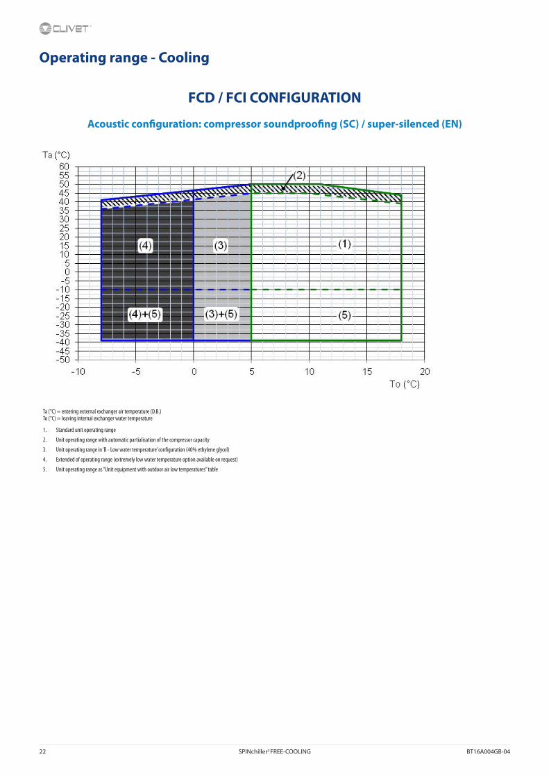
Operating range - Cooling
FCD / FCI CONFIGURATION
Acoustic con�guration: compressor soundproo�ng (SC) / super-silenced (EN)
Ta (°C) = entering external exchanger air temperature (D.B.)To (°C) = leaving internal exchanger water temperature
1. Standard unit operating range
2. Unit operating range with automatic partialisation of the compressor capacity
3. Unit operating range in ‘B - Low water temperature’ con�guration (40% ethylene glycol)
4. Extended of operating range (extremely low water temperature option available on request)
5. Unit operating range as “Unit equipment with outdoor air low temperatures” table

BT16A004GB-04 SPINchiller3 FREE-COOLING 23
Admissible water �ow-ratesMinimum (Qmin) and maximum (Qmax) admissible water �ow for the unit to operate correctly.
EXCELLENCE SC / EN 90.4 100.4 110.4 120.4 140.4 160.4 180.4 200.4 220.4 240.4
Qmin [l/s] 6,7 7,4 8,0 9,3 10,1 11,5 12,8 14,3 15,8 16,4
Qmax [l/s] 18,3 20,0 21,8 25,1 27,5 31,2 34,5 38,6 42,4 44,0
Correction factors for ethylene glycol use% ethylene glycol by weight 5% 10% 15% 20% 25% 30% 35% 40% 50% 60%
Freezing temperature °C -2,0 -3,9 -6,5 -8,9 -11,8 -15,6 -19,0 -23,4 -33,0 -39,0
Safety temperature °C 3,0 1,0 -1,0 -4,0 -6,0 -10,0 -14,0 -19,0 -30,0 -36,0
Cooling Capacity Factor Nr 0,997 0,994 0,990 0,986 0,981 0,976 0,970 0,964 0,950 0,942
Compressor power input Factor Nr 1,000 1,001 1,001 1,001 1,001 1,002 1,002 1,002 1,003 1,003
Internal exchanger glycol solution �ow factor Nr 1,003 1,010 1,020 1,033 1,050 1,072 1,095 1,124 1,184 1,221
Pressure drop Factor Nr 0,989 0,983 0,979 0,980 0,984 0,993 1,004 1,020 1,049 1,073
The correction factors shown refer to water and ethylene glycol mixes used to prevent the formation of frost on the exchangers in the hydraulic circuit during inactivity in winter.
Correction factors for propylene glycol use% propylene glycol by weight 10% 20% 30% 40% 50%
Freezing temperature °C -1,3 -7,1 -12,7 -21,1 -33,5
Safety temperature °C 3,7 -2,1 -7,7 -16,1 -28,5
Cooling Capacity Factor Nr 0,985 0,964 0,932 0,889 0,846
Compressor power input Factor Nr 0,993 0,983 0,969 0,948 0,929
Internal exchanger glycol solution �ow factor Nr 1,017 1,032 1,056 1,092 1,139
Pressure drop Factor Nr 1,120 1,272 1,496 1,792 2,128
The correction factors shown refer to water and propylene glycol mixes used to prevent the formation of frost on the exchangers in the hydraulic circuit during inactivity in winter.
Fouling Correction FactorsInternal exchanger
m2 K / W F1 FK1
0.44 x 10 (-4) 1,0 1,0
0.88 x 10 (-4) 0,97 0,99
1.76 x 10 (-4) 0,94 0,98
F1 = Cooling capacity correction factors FK1 = Compressor power input correction factor
Overload and control device calibrationsopen closed value
High pressure safety pressure switch [kPa] 4050 3300 -
Antifreeze protection [°C] 3 5.5 -
High pressure safety valve [kPa] - - 4500
Low pressure safety valve [kPa] - - 2950
Max no. of compressor starts per hour [n°] - - 10
High compressor discharge temperature safety thermostat [°C] - - 140
Exchanger operating rangeInternal exchanger
DPr DPw
PED (CE) 4500 4500 1000
DPr = Maximum operating pressure on refrigerant side in kPa DPw = Maximum operating pressure on water side in kPa

24 SPINchiller3 FREE-COOLING BT16A004GB-04
FCD / FCI CONFIGURATIONAcoustic con�guration: compressor soundproo�ng (SC)
Cooling performance (continued)
Size To (°C)Entering external exchanger air temperature (ºC)
25 30 35 40 45 50kWf kWe kWf kWe kWf kWe kWf kWe kWf kWe kWf kWe
90.4
5 276 60.3 262 66.1 245 72.8 226 79.9 213 87.9 70.9 28.96 284 60.9 269 66.7 251 73.4 234 80.5 219 89.2 73.1 29.37 293 61.7 277 67.2 261 73.7 242 81.2 231 90.6 77.0 29.8
10 322 63.9 306 69.5 286 76.0 265 83.1 253 92.0 84.5 30.215 367 66.8 346 73.1 323 79.7 300 86.8 182 48.2 - -18 398 69.3 375 75.6 350 82.1 326 89.6 - - - -
100.4
5 299 66.5 285 72.8 267 79.9 247 87.9 231 97.7 142 64.26 308 67.0 293 73.4 275 80.5 254 88.5 239 98.5 147 64.67 319 67.9 301 74.0 284 81.4 265 89.6 248 99.6 153 65.4
10 351 70.3 333 76.8 312 83.9 289 91.8 275 102 169 66.815 399 74.1 378 80.7 353 88.1 328 96.1 215 59.0 - -18 433 77.0 410 83.7 382 91.2 356 99.5 - - - -
110.4
5 334 74.8 315 81.8 295 89.5 275 98.3 257 108 145 63.46 344 75.6 326 82.7 305 90.4 282 99.0 268 109 151 64.17 353 76.4 335 83.5 314 91.3 294 100 280 111 158 64.8
10 391 79.3 369 86.6 345 94.4 319 103 304 113 171 66.015 444 83.6 418 91.0 390 99.0 363 108 218 59.1 - -18 481 87.0 453 94.3 422 102 395 111 - - - -
120.4
5 367 86.1 348 94.2 327 103 302 113 284 121 209 95.36 377 86.9 358 95.1 336 104 313 114 292 122 214 95.87 391 88.1 371 96.3 347 105 326 116 307 123 225 97.1
10 430 91.2 407 99.6 380 109 352 119 334 126 247 99.215 489 96.3 465 105 430 114 403 125 286 83.4 - -18 535 101 504 110 469 119 437 129 - - - -
140.4
5 418 94.5 398 103 374 113 347 123 327 137 182 80.16 429 95.4 409 104 384 114 359 125 335 138 187 80.67 445 96.8 423 106 397 115 373 126 352 140 196 81.8
10 488 101 463 109 435 119 403 130 385 143 215 84.115 554 106 525 115 491 125 457 136 276 75.2 - -18 606 111 568 120 531 130 495 140 - - - -
160.4
5 469 109 444 118 418 129 390 141 366 155 185 81.26 483 110 460 120 433 131 401 142 380 156 192 82.07 499 112 473 121 447 132 417 144 392 158 198 82.8
10 548 116 521 126 489 137 453 148 435 163 220 85.515 622 124 589 134 552 144 513 156 290 73.2 - -18 675 129 638 139 596 149 557 161 - - - -
180.4
5 523 129 497 142 465 156 432 172 403 184 266 1296 543 130 515 143 481 157 443 173 417 186 276 1317 556 132 528 144 496 159 458 174 430 188 285 132
10 614 136 580 149 541 163 499 179 475 192 317 13515 694 143 655 156 609 171 569 187 446 147 - -18 751 149 711 162 658 176 613 192 - - - -
200.4
5 594 137 567 149 532 163 492 179 455 198 266 1296 610 138 583 150 546 164 509 180 469 199 274 1307 631 140 603 152 565 166 522 182 486 201 284 131
10 687 145 648 157 607 171 565 187 529 206 309 13415 786 154 739 166 695 181 647 195 380 108 - -18 845 160 799 172 747 186 694 201 - - - -
220.4
5 640 155 610 169 573 186 533 204 495 219 369 1796 660 156 629 171 589 187 547 206 509 220 380 1807 680 158 646 173 607 189 559 207 520 222 388 181
10 719 162 681 176 643 193 596 213 557 226 417 18415 784 168 746 183 703 200 662 221 488 159 - -18 841 173 802 189 752 205 699 227 - - - -
kWf = Cooling capacity in kW. The data do not consider the part related to the pumps, required to overcome the pressure drop for the solution circulation inside the exchangerskWe = Compressor power input in kWTo (°C) = Leaving internal exchanger water temperature (°C) - Performances in function of the inlet/outlet water temperature di�erential = 5°C

BT16A004GB-04 SPINchiller3 FREE-COOLING 25
FCD / FCI CONFIGURATIONAcoustic con�guration: compressor soundproo�ng (SC)
Cooling performance
Size To (°C)Entering external exchanger air temperature (ºC)
25 30 35 40 45 50kWf kWe kWf kWe kWf kWe kWf kWe kWf kWe kWf kWe
240.4
5 704 174 670 190 626 209 576 230 535 245 389 1936 724 176 688 192 642 211 595 232 552 247 400 1957 743 177 705 194 656 212 606 233 561 248 406 195
10 779 180 736 197 687 216 639 239 592 253 429 19815 854 187 808 204 761 224 704 245 499 165 - -18 920 194 875 211 813 230 753 251 - - - -
kWf = Cooling capacity in kW. The data do not consider the part related to the pumps, required to overcome the pressure drop for the solution circulation inside the exchangerskWe = Compressor power input in kWTo (°C) = Leaving internal exchanger water temperature (°C) - Performances in function of the inlet/outlet water temperature di�erential = 5°C
Pressure drop of the whole unit hydraulic circuitFCD - Direct FREE-COOLING
FCI - No-glycol FREE-COOLING
To the overall (valves, pipes, internal exchangers) pressure drops must be added the pressure drops of the steel mesh mechanical �lter (not supplied) that must be placed on the water input line. It is a device compulsory for the correct unit operation and it must be selected and installed by the Customer. It is forbidden the use of �lters with the mesh pitch higher than 1,0 mm. Filters with higher mesh pitch can cause a bad unit operation and also its serious damaging.
Q = water �ow-rate [l/s]DP = pressure drop water side [kPa]

26 SPINchiller3 FREE-COOLING BT16A004GB-04
FCD / FCI CONFIGURATIONAcoustic con�guration: super-silenced (EN)
Cooling performance (continued)
Size To (°C)Entering external exchanger air temperature (ºC)
25 30 35 40 45 50kWf kWe kWf kWe kWf kWe kWf kWe kWf kWe kWf kWe
90.4
5 284 58.8 268 64.6 251 70.5 232 77.0 214 87.2 74.7 27.26 292 59.4 276 65.0 259 71.4 239 78.1 220 88.5 76.9 27.67 302 60.1 286 65.7 266 71.9 247 79.1 232 89.8 81.1 28.0
10 331 62.2 312 67.9 292 74.7 271 81.2 255 91.2 89.0 28.415 378 65.8 354 71.9 330 78.0 308 85.0 183 47.8 - -18 409 68.3 382 74.5 355 81.0 336 87.6 - - - -
100.4
5 306 64.7 289 70.8 270 77.6 250 85.1 231 96.4 149 60.16 314 65.3 298 71.5 280 78.5 259 86.0 238 97.1 154 60.67 325 66.2 308 72.4 287 79.2 267 87.0 248 98.2 160 61.2
10 357 68.6 337 74.9 316 82.2 291 89.5 275 100 177 62.615 407 72.9 383 79.3 357 86.3 333 94.3 214 58.2 - -18 440 76.0 414 82.5 388 90.0 363 97.5 - - - -
110.4
5 337 73.0 318 79.8 296 87.2 274 95.3 254 107 150 59.36 346 73.7 326 80.6 306 88.2 283 96.4 264 108 156 59.97 358 74.7 337 81.6 316 89.2 293 97.4 277 109 163 60.6
10 391 77.5 368 84.4 342 92.0 318 100 301 111 177 61.715 445 82.5 417 89.4 388 96.9 365 105 216 58.2 - -18 480 85.7 449 92.8 423 101 397 109 - - - -
120.4
5 374 83.0 353 90.8 332 99.6 307 109 287 122 151 59.96 387 84.1 366 91.9 341 101 315 110 294 122 155 60.27 398 84.9 375 92.9 354 102 328 111 310 124 163 61.0
10 439 88.5 413 96.4 384 105 356 115 339 127 178 62.415 496 94.1 465 102 433 111 406 120 226 56.9 - -18 536 98.3 501 106 467 115 443 125 - - - -
140.4
5 430 93.7 407 102 381 112 355 122 328 138 192 76.66 445 95.1 422 104 394 113 365 123 336 138 196 77.17 457 96.1 432 105 404 114 379 125 354 140 207 78.2
10 503 100 475 109 443 118 412 129 387 144 226 80.415 568 107 535 115 499 125 467 135 277 75.6 - -18 613 111 577 120 539 129 508 140 - - - -
160.4
5 485 107 460 116 430 126 401 137 369 153 196 76.36 498 108 472 117 444 128 412 139 383 155 203 77.17 515 109 488 119 455 129 426 140 396 156 210 77.8
10 563 114 532 123 497 134 462 145 439 161 233 80.315 640 122 603 131 562 141 527 153 293 72.3 - -18 690 127 649 137 606 147 573 159 - - - -
180.4
5 542 127 512 139 475 153 440 168 421 181 282 1256 557 128 524 141 490 155 452 170 435 182 292 1277 576 130 540 143 502 156 469 172 450 184 302 128
10 626 135 592 147 549 161 508 176 495 189 336 13115 709 143 663 155 615 169 578 184 463 144 - -18 762 148 712 161 662 175 631 190 - - - -
200.4
5 604 131 573 143 534 157 496 172 452 192 277 1196 623 134 590 146 551 159 509 173 466 194 285 1207 639 135 607 147 566 160 524 176 483 196 296 121
10 694 140 657 152 612 165 566 180 525 200 322 12415 790 149 742 161 692 174 645 188 405 113 - -18 844 155 799 168 746 180 694 194 - - - -
220.4
5 668 147 632 161 591 177 544 193 504 217 284 1186 688 149 650 163 606 178 561 195 518 218 292 1197 705 150 668 165 623 180 574 197 529 219 298 120
10 745 154 699 168 649 183 598 200 570 222 321 12115 811 160 766 174 715 190 669 208 409 117 - -18 872 166 820 180 770 197 718 213 - - - -
kWf = Cooling capacity in kW. The data do not consider the part related to the pumps, required to overcome the pressure drop for the solution circulation inside the exchangerskWe = Compressor power input in kWTo (°C) = Leaving internal exchanger water temperature (°C) - Performances in function of the inlet/outlet water temperature di�erential = 5°C

BT16A004GB-04 SPINchiller3 FREE-COOLING 27
FCD / FCI CONFIGURATIONAcoustic con�guration: super-silenced (EN)
Cooling performance
Size To (°C)Entering external exchanger air temperature (ºC)
25 30 35 40 45 50kWf kWe kWf kWe kWf kWe kWf kWe kWf kWe kWf kWe
240.4
5 736 163 694 179 647 197 594 216 569 232 421 1806 755 165 711 181 663 199 610 218 585 234 434 1817 774 167 730 183 675 200 621 219 594 235 440 182
10 813 170 761 186 705 203 648 222 624 238 464 18415 885 177 830 193 776 211 728 231 527 156 - -18 952 184 891 200 826 217 782 237 - - - -
kWf = Cooling capacity in kW. The data do not consider the part related to the pumps, required to overcome the pressure drop for the solution circulation inside the exchangerskWe = Compressor power input in kWTo (°C) = Leaving internal exchanger water temperature (°C) - Performances in function of the inlet/outlet water temperature di�erential = 5°C
Pressure drop of the whole unit hydraulic circuitFCD - Direct FREE-COOLING
FCI - No-glycol FREE-COOLING
To the overall (valves, pipes, internal exchangers) pressure drops must be added the pressure drops of the steel mesh mechanical �lter (not supplied) that must be placed on the water input line. It is a device compulsory for the correct unit operation and it must be selected and installed by the Customer. It is forbidden the use of �lters with the mesh pitch higher than 1,0 mm. Filters with higher mesh pitch can cause a bad unit operation and also its serious damaging.
Q = water �ow-rate [l/s]DP = pressure drop water side [kPa]

28 SPINchiller3 FREE-COOLING BT16A004GB-04
FCD - Direct FREE-COOLINGCon�gurtion that allows for considerable savings on the system’s running costs in applications that require chilled water also during the cold season, such as industrial processes, data centres, telecommunications, technological applications and shopping centres. When the outdoor air temperature is lower than the temperature of the system’s return water, the FREE-COOLING system recovers cold from the external environment and reduces the operation of the compressors until they stop completely. The higher the temperature of the chilled water in the system (e.g. 10-15°C instead of 7-12°C), the greater the operating range of the FREE-COOLING system and, therefore, the higher the energy savings.
Use of anti-freeze solutionsThe FREE-COOLING con�guration is particularly indicated in buildings where, at least in certain periods of the year, the temperature of the outdoor air also reaches very low values. For this reason the liquid must be protected from the risk of freezing, typically using the addition of a suitable anti-freeze substance such as ethylene glycol. The percentage of glycol in the solution depends on the minimum temperature value foreseen in the installation zone, and is in any case within the fundamental parameters of the plan for the system.
Management logicThere are three main operating modes, which basically di�er in terms of position of the three-way switching valve and the number of active compressors.
(A) SummerIn the summer season, with outdoor air temperatures which are greater than the return temperature of the liquid in the system, the three-way valve is switched in such a way as to exclude the FREE-COOLING coils. The cooling of the liquid is referred to the direct expansion circuit, with the intervention of the compressors as in a traditional chiller.
(B) Intermediate seasonIn the winter season, or rather with the outdoor air temperature at a little below the return water temperature of the system, when the unit identi�es that the temperature conditions are favourable:
• switches the position of the tree-way valve, forcing the solution to transit through the FRE-COOLING coils before reaching the evaporator;
• brings the fans to maximum speed to make the most of the cooling of the solution carried out by the outdoor air
• conducts a �rst cooling of the solution in a ‘natural way and free of charge’;
• provides any missing capacity via the cooling circuit using compressors with partial operation (power input proportional to the partialisation level).
If the outdoor air temperature should increase, the microprocessor automatically converts the operating mode to the summer mode, guaranteeing the conditions requested by the user at all times.
(C) WinterIn the winter season, with the outdoor air temperature below the return water temperature of the system, the unit identi�es that the temperature conditions are favourable for operating in FREE-COOLING mode:
• the 3-way valve is switched like in the previous case, forcing the solution to transit through the FREE-COOLING coils before reaching the evaporator;
• the outdoor air temperature brings the solution at the outlet of the FREE-COOLING coils already at the temperature required by the utility;
• the microprocessor control completely deactivates all the compressors which supply all the requested cooling capacity at no cost, in contrast to traditional chillers.
The di�erence between the outdoor air temperature and that requested for use could also be such as to lower the temperature of the solution at the output of the FREE-COOLING coils to below the set-point requested for use. This is a condition which does not prejudice the safety of the unit thanks to the presence of anti-freeze in the solution. The microprocessor modulates fan speed up to the point where they are switched o�. If, with all the fans switched, o� the temperature continues to decrease, the three-way valve positions itself automatically in the summer operational mode, thus enabling the requested set-point to be maintained.
1 - Internal exchanger 5 -External fan TW in chilled water inlet2 -Three-way valve for FREE-COOLING 6 -Expansion electronic valve TW out chilled water outlet3 -Compressors T - Temperature probe AE - Outdoor air4 - External exchanger PD - Di�erential pressure switch
Check availability and compatibility of ‘FCD - Direct FREE-COOLING’ with the other accessories in the “Option compatibility” table.
Con�gurationsConsult the “Option compatibility” section.
B - Low water temperature (Brine)Con�guration also known as “Brine”. Enables an “unfreezable” solution to be cooled (for example, water and ethylene glycol in suitable quantities) up to a temperature of between +4°C and –8°C. It includes:
• suitable exchangers with extra-thick closed-cell insulation;
• electronic expansion valve, functional calibration and safety devices suitable for particular uses.
During the selection phase it is necessary to indicate the required operating type, the unit will be optimised on the basis of this: - Unit with single operating set-point (only at low temperature) - Unit with double operating set-point.
The unit in this con�guration has a di�erent operation range, indicated in the operating range section.
In low temperature operation, some staging steps could not be available.
The glycol concentration must be chosen based on the minimum temperature the water can reach. The presence of glycol in�uences pressure drops on the water side and the unit’s output as indicated in the table reporting the ”correction factors for use with glycol”.

BT16A004GB-04 SPINchiller3 FREE-COOLING 29
Determination of chiller performance with direct FREE-COOLING in conditions of FC = ON
Size 90.4 100.4 110.4 120.4 140.4 160.4 180.4 200.4 220.4 240.4
SCFREE-COOLING (1) nominal capacity kW 299 325 361 397 452 509 566 632 664 718
Air temperature with FREE-COOLING at 100% (1) °C 1,2 0,4 -0,5 -1,4 1,3 0,2 -0,9 0,8 0,3 -0,6
ENFREE-COOLING (1) nominal capacity kW 305 329 359 403 464 519 578 641 683 742
Air temperature with FREE-COOLING at 100% (1) °C 3,5 3,2 2,8 2,1 3,4 2,6 1,8 2,7 2,2 1,5
(1) Data refer to the following conditions:- water temperature: 15°C inlet / 10°C outlet- glycol percentage 30%
Determination of the direct FREE-COOLING percentage - SC con�guration
Determination of the direct FREE-COOLING percentage - EN con�guration
Example: Determine the performances with outdoor air = +2°C for the following unit: WSAT-XSC3 90.4 FCD EXC SC (EXCELLENCE version, direct FREE-COOLING con�guration), with water 15/10 °C / 30% glycol.
Reference: WSAT-XSC3 90.4 FCD EXC SC: FREE-COOLING nominal capacity = 299 kW (from table with water 15/10 °C / 30% glycol/ outdoor air temperature 1,2°C).
Calculation: Di�erence between the installation return water and the outdoor air = 15°C - 2°C = 13°C.
The graph shows that: FREE-COOLING percentage = 93%: direct FREE-COOLING capacity at +2°C outdoors = 299 x 93% = 278 kW.
KEYDT [°C] = Temperature di�erence between the system return water and the outdoor air
% FC = FREE-COOLING percentage (in relation to the rated FREE-COOLING capacity)

30 SPINchiller3 FREE-COOLING BT16A004GB-04
FCI - No-glycol FREE-COOLINGCon�gurtion that allows for considerable savings on the system’s running costs in applications that require chilled water also during the cold season, such as industrial processes, data centres, telecommunications, technological applications and shopping centres. Does not require the addition of an antifreeze substance in the hydraulic circuit used. Therefore, it is particularly suitable for large-sized systems and wherever laws and regulations limit the use of antifreeze substances inside buildings. Moreover, it does not a�ect the performance of terminal units and the system’s pumping units. When the outdoor air temperature is lower than the temperature of the system’s return water, the FREE-COOLING system recovers cold from the external environment and reduces the operation of the compressors until they stop completely. The higher the temperature of the chilled water in the system (e.g. 10-15°C instead of 7-12°C), the greater the operating range of the FREE-COOLING system and, therefore, the higher the energy savings.
Management logic
There are three main operating modes, which basically di�er in terms of activation of the FREE-COOLING circuit electric pump and the number of active compressors:
(A) Summer
In the summer season, with outdoor air temperatures which are greater than the return temperature of the liquid in the system, the electric pump is o� and the �uid circulation by the FREE-COOLING coils is not present. The cooling of the liquid is referred to the direct expansion circuit, with the intervention of the compressors as in a traditional chiller.
(B) Intermediate season
In the winter season, or rather with the outdoor air temperature at a little below the return water temperature of the system, when the unit identi�es that the temperature conditions are favourable:
• activates the electric pump of the FREE-COOLING circuit by creating an exchange of energy between the liquid in the system and the FREE-COOLING circuit before reaching the evaporator;
• brings the fans to maximum speed to make the most of the cooling of the solution carried out by the outdoor air;
• conducts a �rst cooling of the solution in a ‘natural way and free of charge’;
• provides any missing capacity via the cooling circuit using compressors with partial operation (power input proportional to the partialisation level);
If the outdoor air temperature should increase, the microprocessor automatically converts the operating mode to the summer mode, guaranteeing the conditions requested by the user at all times.
(C) Winter
In the winter season, with the outdoor air temperature below the return water temperature of the system, the unit identi�es that the temperature conditions are favourable for operating in FREE-COOLING mode:
• as in the previous scenario, it activates the electric pump on the FREE-COOLING circuit by creating an exchange of energy between the liquid in the system and the FREE-COOLING circuit before reaching the evaporator;
• acts on the speed of the fans until it turns them o� in order to reach the temperature required on the system’s supply line;
• the microprocessor control turns o� all the compressors by releasing all the desired cooling capacity AT ZERO COST, unlike traditional chillers;
If the temperature keeps dropping with all the fans o�, the electric pump turns o�, which allows the desired set point value to be maintained.
1 - Internal exchanger 5 -External fan TW in chilled water inlet2 -Water-water intermediate exchanger 6 -Expansion electronic valve TW out chilled water outlet3 -Compressors T - Temperature probe AE Outdoor air4 - External exchanger PD - Di�erential pressure switch PD - Di�erential pressure switch
Check availability and compatibility of ‘FCI - No-glycol FREE-COOLING’ with the other accessories in the “Option compatibility” table

BT16A004GB-04 SPINchiller3 FREE-COOLING 31
Determination of chiller performance with no-glycol FREE-COOLING in conditions of FC = ON
Size 90.4 100.4 110.4 120.4 140.4 160.4 180.4 200.4 220.4 240.4
SCFREE-COOLING (1) nominal capacity kW 306 333 369 407 463 521 580 648 681 736
Air temperature with FREE-COOLING at 100% (1) °C 0,5 -0,3 -1,3 -2,4 -0,2 -1,4 -2,7 -1,2 -1,7 -2,7
ENFREE-COOLING (1) nominal capacity kW 312 337 368 413 475 532 592 657 699 761
Air temperature with FREE-COOLING at 100% (1) °C 2,8 2,4 1,7 0,8 1,7 0,8 -0,1 0,7 0,1 -0,7
(1) Data refer to the following conditions:- water temperature: 15°C inlet / 10°C outlet- % of glycol in the system: 10%;- % of glycol in the unit internal closed circuit: 30%.
Determination of the no-glycol FREE-COOLING percentage - SC con�guration
Determination of the no-glycol FREE-COOLING percentage - EN con�guration
Example: Determine the performances with outdoor air = +2°C for the following unit: WSAT-XSC3 90.4 FCI EXC SC (EXCELLENCE version, No-glycol FREE-COOLING con�guration), with water at 15/10 °C / 0% of glycol in the system.
Reference: WSAT-XSC3 90.4 FCI EXC SC: FREE-COOLING nominal capacity = 306 kW (from table with water 15/10 °C / outdoor air temperature 0,5°C).
Calculation: Di�erence between the installation return water and the outdoor air = 15°C - 2°C = 13°C.
The graph shows that: FREE-COOLING percentage = 86% : FREE-COOLING capacity at +2°C outdoors = 306 x 86% = 263 kW.
KEYDT [°C] = Temperature di�erence between the system return water and the outdoor air
% FC = FREE-COOLING percentage (in relation to the rated FREE-COOLING capacity)

32 SPINchiller3 FREE-COOLING BT16A004GB-04
WOGLY - Unit supplied without glycol solutionThe standard unit is supplied with antifreeze solution in the FREE-COOLING separated circuit. With WOGLY option the unit is supplied without antifreeze solution with the advantage of a reduction of shipping weight of 10% as well as a saving on the initial investment.
The antifreeze solution supply and charge are provided by the Customer. Refer to the Installation and Operating manual for the charging procedures.
For the water + glycol solution content, refer to the ‘ Quantity of glycol in the no-glycol FREE-COOLING’ table.
Option valid in combination with ‘FCI - no-glycol FREE-COOLING’.
Quantity of glycol in the no-glycol FREE-COOLING
Size 90.4 100.4 110.4 120.4 140.4 160.4 180.4 200.4 220.4 240.4
SC
Water solution total volume + glycol l 218 220 224 232 286 292 298 358 364 370
30% ethylene glycol
Freezing temperature °C -15,4
Ethylene glycol volume l 65 66 67 70 86 88 89 107 109 111
Glycol solution total weight kg 226 228 232 240 296 303 309 371 377 383
40% ethylene glycol
Freezing temperature °C -23,4
Ethylene glycol volume l 87 88 90 93 114 117 119 143 146 148
Glycol solution total weight kg 229 231 235 243 300 306 312 375 382 388
50% ethylene glycol
Freezing temperature °C -33,0
Ethylene glycol volume l 109 110 112 116 143 146 149 179 182 185
Glycol solution total weight kg 231 233 238 246 303 310 316 380 386 392
60% ethylene glycol
Freezing temperature °C -39,0
Ethylene glycol volume l 131 132 134 139 172 175 179 215 218 222
Glycol solution total weight kg 234 236 240 249 307 313 320 384 390 397
Size 90.4 100.4 110.4 120.4 140.4 160.4 180.4 200.4 220.4 240.4
EN
Water solution total volume + glycol l 262 270 273 278 358 364 370 398 401 414
30% ethylene glycol
Freezing temperature °C -15,4
Ethylene glycol volume l 79 81 82 83 107 109 111 119 120 124
Glycol solution total weight kg 271 280 283 288 371 377 383 412 416 429
40% ethylene glycol
Freezing temperature °C -23,4
Ethylene glycol volume l 105 108 109 111 143 146 148 159 160 166
Glycol solution total weight kg 275 283 286 291 375 382 388 417 420 434
50% ethylene glycol
Freezing temperature °C -33,0
Ethylene glycol volume l 131 135 137 139 179 182 185 199 201 207
Glycol solution total weight kg 278 286 289 295 380 386 392 422 425 439
60% ethylene glycol
Freezing temperature °C -39,0
Ethylene glycol volume l 157 162 164 167 215 218 222 239 241 248
Glycol solution total weight kg 281 290 293 298 384 390 397 427 430 444
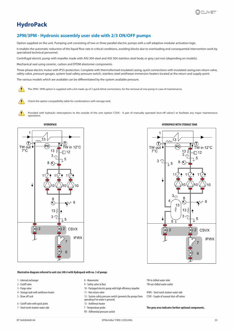
BT16A004GB-04 SPINchiller3 FREE-COOLING 33
HydroPack
2PM/3PM - Hydronic assembly user side with 2/3 ON/OFF pumpsOption supplied on the unit. Pumping unit consisting of two or three parallel electric pumps with a self-adaptive modular activation logic.
It enables the automatic reduction of the liquid �ow rate in critical conditions, avoiding blocks due to overloading and consequential intervention work by specialised technical personnel.
Centrifugal electric pump with impeller made with AISI 304 steel and AISI 304 stainless steel body or grey cast iron (depending on models).
Mechanical seal using ceramic, carbon and EPDM elastomer components.
Three-phase electric motor with IP55-protection. Complete with thermoformed insulated casing, quick connections with insulated casing,non return valve, safety valve, pressure gauges, system load safety pressure switch, stainless steel antifreeze immersion heaters located at the return and supply point.
The various models which are available can be di�erentiated by the system available pressure.
The 2PM / 3PM option is supplied with a kit made up of 2 quick blind connections, for the removal of one pump in case of maintenance.
Check the option compatibility table for combinations with storage tank.
Provided with hydraulic interceptions to the outside of the unit (option ‘CSVX - A pair of manually operated shut-o� valves’) to facilitate any major maintenance operations.
HYDROPACK HYDROPACK WITH STORAGE TANK
Illustrative diagram referred to unit size 240.4 with Hydropack with no. 3 of pumps
1 - Internal exchanger 8 - Manometer TW in chilled water inlet2 - Cuto� valve 9 - Safety valve (6 Bar) TW out chilled water outlet3 - Purge valve 10 - Packaged electric pump with high e�ciency impeller4 - Storage tank with antifreeze heater 11 - Non return valve IFWX - Steel mesh strainer water side5 - Draw o� cock 12 - System safety pressure switch (prevents the pumps from
operating if no water is present)CSVX - Couple of manual shut-o� valves
6 - Cuto� valve with quick joints 13 - Antifreeze heater7 - Steel mesh strainer water side T - Temperature probe The grey area indicates further optional components.
PD - Di�erential pressure switch
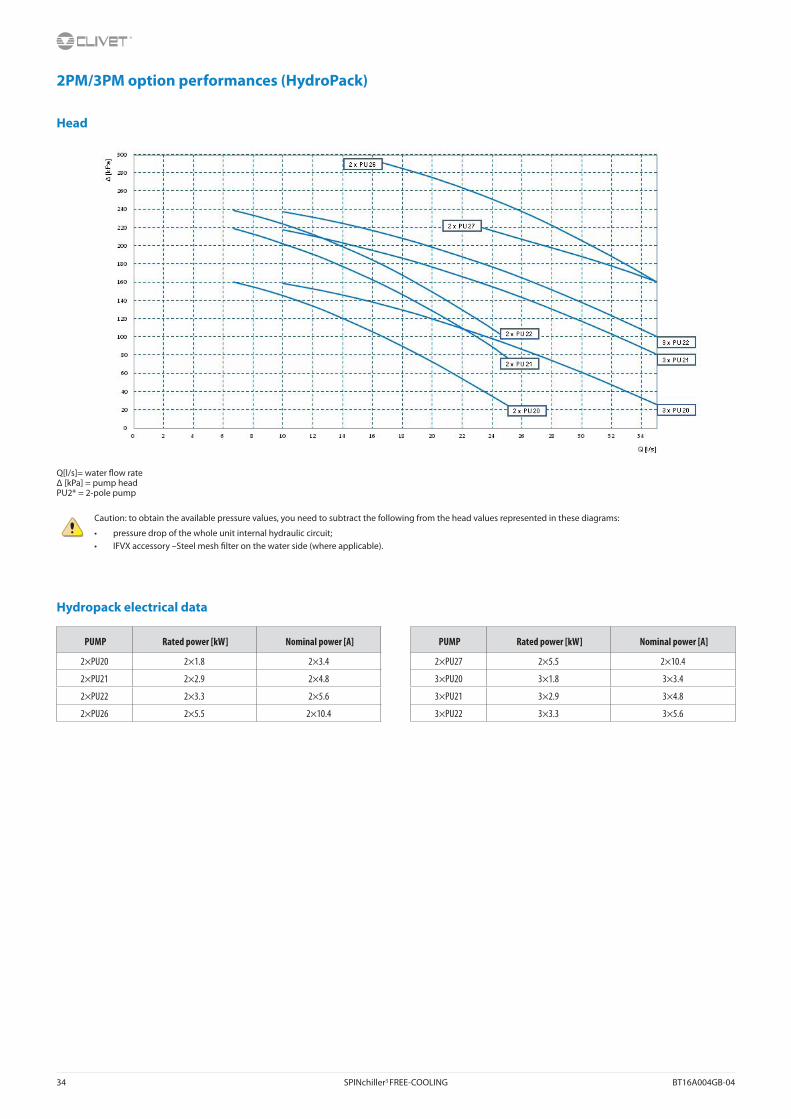
34 SPINchiller3 FREE-COOLING BT16A004GB-04
2PM/3PM option performances (HydroPack)
Head
Q[l/s]= water �ow rateΔ [kPa] = pump headPU2* = 2-pole pump
Caution: to obtain the available pressure values, you need to subtract the following from the head values represented in these diagrams:
• pressure drop of the whole unit internal hydraulic circuit;• IFVX accessory –Steel mesh �lter on the water side (where applicable).
Hydropack electrical data
PUMP Rated power [kW] Nominal power [A] PUMP Rated power [kW] Nominal power [A]
2×PU20 2×1.8 2×3.4 2×PU27 2×5.5 2×10.4
2×PU21 2×2.9 2×4.8 3×PU20 3×1.8 3×3.4
2×PU22 2×3.3 2×5.6 3×PU21 3×2.9 3×4.8
2×PU26 2×5.5 2×10.4 3×PU22 3×3.3 3×5.6

BT16A004GB-04 SPINchiller3 FREE-COOLING 35
2PMV/3PMV - Hydronic assembly user side with 2/3 inverter pumpsOption supplied on the unit. Pumping unit consisting of parallel electric pumps and controlled by inverter to adapt to the di�erent application conditions.
It enables the automatic reduction of the liquid �ow rate in critical conditions, avoiding blocks due to overloading and consequential intervention work by specialised technical personnel.
Through the inverter calibration, standard supplied, it is possible to adapt the pump �ow-rate/head to the installation feature.
Centrifugal electric pump with impeller made with AISI 304 steel and AISI 304 stainless steel body or grey cast iron (depending on models).
Mechanical seal using ceramic, carbon and EPDM elastomer components.
Three-phase electric motor with IP55-protection. Complete with thermoformed insulated casing, quick connections with insulated casing,non return valve, safety valve, pressure gauges, system load safety pressure switch, stainless steel antifreeze immersion heaters located at the return and supply point.
In combination with the “IVFDT” - Variable �ow-rate control option, it allows the water �ow rate variation to the installation in part load operation to obtain the maximum unit e�ciency and lower pumping unit consumption.
The 2PMV / 3PMV option is supplied with a kit made up of 2 quick blind connections, for the removal of one pump in case of maintenance.
Check the option compatibility table for combinations with storage tank.
Provided with hydraulic interceptions to the outside of the unit (option ‘CSVX - A pair of manually operated shut-o� valves’) to facilitate any major maintenance operations.
1 - Internal exchanger 8 - Manometer PD - Di�erential pressure switch2 - Cuto� valve 9 - Safety valve (6 Bar) TW in chilled water inlet3 - Purge valve 10 - Packaged electric pump with high e�ciency impeller
activated by inverterTW out chilled water outlet
4- Storage tank 11 - Non return valve5 - Draw o� cock 12 - System safety pressure switch (prevents the pumps from
operating if no water is present)IFWX - Steel mesh strainer water side
6 - Cuto� valve with quick joints 13 - Antifreeze heater CSVX - Couple of manual shut-o� valves7 - Steel mesh strainer water side The grey area indicates further optional components.
T - Temperature probe

36 SPINchiller3 FREE-COOLING BT16A004GB-04
2PMV option performances
Head
Q[l/s]= water �ow rateΔ [kPa] = pump head
Caution: to obtain the available pressure values, you need to subtract the following from the head values represented in these diagrams:
• pressure drop of the whole unit internal hydraulic circuit;• IFVX accessory –Steel mesh �lter on the water side (where applicable).
Power input
Q[l/s]= water �ow ratekW = power input

BT16A004GB-04 SPINchiller3 FREE-COOLING 37
3PMV option performances
Head
Q[l/s]= water �ow rateΔ [kPa] = pump head
Caution: to obtain the available pressure values, you need to subtract the following from the head values represented in these diagrams:
• pressure drop of the whole unit internal hydraulic circuit;• IFVX accessory –Steel mesh �lter on the water side (where applicable).
Power input
Q[l/s]= water �ow ratekW = power input
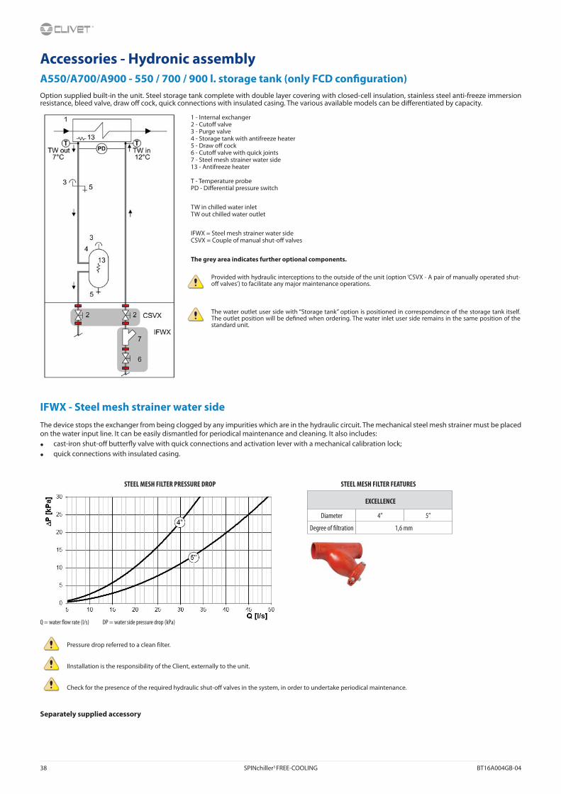
38 SPINchiller3 FREE-COOLING BT16A004GB-04
Accessories - Hydronic assemblyA550/A700/A900 - 550 / 700 / 900 l. storage tank (only FCD con�guration)Option supplied built-in the unit. Steel storage tank complete with double layer covering with closed-cell insulation, stainless steel anti-freeze immersion resistance, bleed valve, draw o� cock, quick connections with insulated casing. The various available models can be di�erentiated by capacity.
IFWX - Steel mesh strainer water sideThe device stops the exchanger from being clogged by any impurities which are in the hydraulic circuit. The mechanical steel mesh strainer must be placed on the water input line. It can be easily dismantled for periodical maintenance and cleaning. It also includes:
• cast-iron shut-o� butter�y valve with quick connections and activation lever with a mechanical calibration lock;
• quick connections with insulated casing.
STEEL MESH FILTER PRESSURE DROP STEEL MESH FILTER FEATURES
EXCELLENCE
Diameter 4” 5”
Degree of �ltration 1,6 mm
Q = water �ow rate (l/s) DP = water side pressure drop (kPa)
Pressure drop referred to a clean �lter.
IInstallation is the responsibility of the Client, externally to the unit.
Check for the presence of the required hydraulic shut-o� valves in the system, in order to undertake periodical maintenance.
Separately supplied accessory
1 - Internal exchanger2 - Cuto� valve3 - Purge valve4 - Storage tank with antifreeze heater5 - Draw o� cock6 - Cuto� valve with quick joints7 - Steel mesh strainer water side13 - Antifreeze heater
T - Temperature probePD - Di�erential pressure switch
TW in chilled water inletTW out chilled water outlet
IFWX = Steel mesh strainer water sideCSVX = Couple of manual shut-o� valves
The grey area indicates further optional components.
Provided with hydraulic interceptions to the outside of the unit (option ‘CSVX - A pair of manually operated shut-o� valves’) to facilitate any major maintenance operations.
The water outlet user side with “Storage tank” option is positioned in correspondence of the storage tank itself. The outlet position will be de�ned when ordering. The water inlet user side remains in the same position of the standard unit.

BT16A004GB-04 SPINchiller3 FREE-COOLING 39
Accessories
PGFC- Finned coil protection grillGrilles made in drawn of electro-welded steel and coated to protect the external coil from accidental contact with people and things.
The protection grill has a height equal to the whole unit. Therefore, all areas under the coils are protected.
This accessory also protects the rear area of the unit opposite to the electric panel.
Ideal for installation in places where persons can pass from, such as car parks, terraces, etc.
Accessories supplied and installed built-in the unit.
PGCCH - Anti-hail protection grillesGrilles made in drawn of electro-welded steel and coated suitable to protect the external coil from hail damage.
Accessories supplied and installed built-in the unit.
CCCA - Copper / aluminium condenser coil with acrylic liningCondensing coils with copper pipes and aluminum �ns with acrylic lacquering. Can be used in settings with moderately aggressive low saline concentrations and other chemical agents. The acrylic coating is used as the most economical and e�ective method particularly in protecting aluminum surfaces exposed to the corrosive in�uence of the humid and salty air in regions with marine climates.
Attention!
- Cooling capacity variation -2.7%
- Variation in compressor power input +4.2%
- Operating range reduction -2.1°C
Option available only on special request
CCCA1 - Copper / aluminium condenser coil with Aluminium Energy Guard DCC treatmentCondensing coils with copper pipes and aluminum �ns with Aluminium Energy Guard DCC treatment. Complete treatment which o�ers an optimal thermal exchange and guarantees and protects the �nned coil exchangers from corrosion over time and UV rays. Can be used in settings with very aggressive saline concentrations and other chemical agents in the air thus maintaining the performance of the coils over time and with negligible pressure drop.
Option available only on special request
MHP - High and low pressure gaugesIt includes two liquid pressure gauges for the analog measurement of refrigerant pressures on suction and discharge lines of the compressors with pressure sockets installed in the unit in an easily accessible location.
Device supplied and installed built-in the unit.

40 SPINchiller3 FREE-COOLING BT16A004GB-04
SDV - Cuto� valve on compressor supply and returnAn option which integrates the supply cuto� valve, which is supplied as standard. The presence of the cock at the intake as well enables the compressors to be isolated and substituted without discharging the refrigerant from within the refrigeration circuit. This means that the extraordinary maintenance activities are facilitated.
The device is installed built-in the unit.
RE-20 / RE-25 / RE-30 / RE-35 / RE-39 - Electrical panel anti-freeze protectionIt includes self-regulating electric heaters with thermost which are able to protect the electrical panel against condensation and frost guaranteeing its correctly functions down to -39°C. This accessory operates even when the unit is switched o� provided that the power supply is maintained active and the unit continues to be electrically connected.
Device installed and wired built-in the unit.
This accessory operates even when the unit is switched o� provided that the power supply is maintained active and the unit continues to be connected.
This accessory does not lead to substantial variations in the electrical data for the unit which has been declared in the Electrical Data section.
PFCP - Power-factor correction capacitors (cos� > 0.9)Component is necessary to lower the phase di�erence between current and voltage in the electromagnetic components of the unit (e.g. asynchronous motors). The component allows to put the cos� power factor to values on average higher than 0.9, reducing the network reactive power.
Device installed and wired built-in the unit.
ECS - ECOSHARE function for the automatic management of a group of unitsDevice allows automatic management of units that operate on the same hydraulic circuit, by creating a local communication network. There are three control modes that can be set via a parameter during the units stat-up.
Two control modes distribute the heat load on the available units by following the distribution logic to bene�t of e�ciency levels at part load and one shift the supply water set-point temperature on the group of units. Moreover:
Mode 0 - shift the water set-point temperature and keeps all the pumps active;
Mode 1 - distribute the heat load and keeps all the pumps active;
Mode 2 - distribute the heat load and activates only the pumps of the unit required to operate.
The device allows for rotation based on the criterion of minimum wear and management of units in stand-by. In case of failure of one unit the load is distributed in the other units. The units can be of various sizes but of the same type: all reversible heat pumps, or all air-cooled liquid chiller.The set of units is controlled by a Master unit.
The local network can be extended up to 7 units (1 Master and 6 Slave).
The unit supplied with this device can also be equipped at the same time with the RCMRX option and one of the CMSC11 / CMSC9 / CMSC10 options.
1. Compressors
2. Cuto� valve
3. Safety valve
4. SDV option

BT16A004GB-04 SPINchiller3 FREE-COOLING 41
SFSTR – Disposal for inrush current reduction (SOFT STARTER)Electronic device which automatically starts up the compressors gradually, reducing the starting current forthe unit by around 40% in comparison with the nominal value. This results in the reduction of the startingtorque of the ON/OFF compressor, it is more protected from mechanical stresses leading to an increased life of the component. The noise is also reduced.
Device installed and wired built-in the unit.
In sizes 180.4, 200.4, 220.4 and 240.4 the larger size compressor is standard equipped with device for progressive start-up, de�ned part-winding. For these units the soft-starter bene �ts are guaranteed on lower size compressors, maintaining unchanged the M.I.C. (max. inrush current) of the standard unit.
The compressors with 60 HP of nominal capacity need the standard device for the progressive start-up de�ned part-winding.
CMSC11 - Serial communication module for BACnet supervisorModule allows the serial connection of the supervision system, using BACnet/IP as the communication protocol. It enables access to the complete list of operational variables, commands and alarms. Using this accessory every unit can dialogue with the main supervision systems.
Device installed and wired built-in the unit.
The con�guration and management activities for the BACnet networks are the responsibility of the client.
The total length of each serial line do not exceed 1000 meters and the line must be connected in bus typology (in/out).
CMSC9 - Serial communication module for Modbus supervisorModule allows the serial connection of the supervision system, using Modbus as the communication protocol. It enables access to the complete list of operational variables, commands and alarms. Using this accessory every unit can dialogue with the main supervision systems.
Device installed and wired built-in the unit.
The total length of each serial line do not exceed 1000 meters and the line must be connected in bus typology (in/out).
CMSC10 - Serial communication module for LonWorks supervisorModule allows the serial connection of the supervision system which uses the LonWorks communication protocol. It enables access to a list of operating variables, commands and alarms which comply with the Echelon® standard.
Device installed and wired built-in the unit.
The con�guration and management activities for the LonWorks networks are the responsibility of the client.
LonWorks technology uses the LonTalk® protocol for communicating between the network nodes. Contact the service supplier for further information.
The total length of each serial line do not exceed 1000 meters and the line must be connected in bus typology (in/out).
CREFB - Device for consumption reduction of the external section ECOBREEZE fans An option which regards the external helical fans, as an alternative to the phase-cut device. It provides for an IP54 brushless electronically commutated electrical motor and incorporated thermal protection. Supplied with variable speed control.
Standard in EN version.
CREFP - Device for fan consumption reduction of the external section at variable speed (phase-cutting) An option which regards the external helical fans, as an alternative to the phase-cut device. It provides for an IP54 three-phase electrical motor with an external rotor and incorporated thermal protection. Supplied with variable speed control.
Device installed and wired built-in the unit.
Standard in SC version.
Option available for sizes from 90.4 to 180.4 in EXC version, EN acoustic con�guration.
–– Absorbed current without SFSTR option− Absorbed current without SFSTR option

42 SPINchiller3 FREE-COOLING BT16A004GB-04
CONTA2 - Energy meterAllows to display and record the unit’s main electrical parameters. The data can be displayed on the device display or via the supervisor through the speci�c protocol variables. The device has a serial port with Modbus protocol for connection to the supervisory system. It is possible to control:
- voltage (V),
- absorbed current (A),
- frequency (Hz), - cos�,
- power input (KW),
- absorbed energy (KWh),
- harmonic components (%).
Device installed and wired built-in the unit.
On the device is present a serial port with Modbus protocol for the connection to the supervision system.
SCP4 - Set-point compensation with 0-10 V signalDevice allows the changing of the preset set point by means to an external 0÷10 V signal. The interruption of the signal the set-point is at the nominal set value. The limit values can be changed within wide values.
Device installed and wired built-in the unit.
SPC2 - Set-point compensation with outdoor air temperature probeDevice allows the automatic regulation of the preset set-point depending of the outside temperature air measured by the unit probe. This device allows to get the sliding supply water temperature, which varies depending on external conditions, enabling energy savings throughout the entire system.
The device is installed and wired built-in the unit.
IVFDT - Inverter driven variable �ow-rate user side control depending on the temperature di�erential Option allows water �ow-rate modulation to the unit during partial load conditions, maintaining stable the temperature di�erence between inlet and outlet to the heat exchanger.
The option is available only when the unit thermoregulation is set on the return temperature.
Designed for systems with primary circuit variable �ow-rate systems decoupled from secondary circuit. With no building load the unit switches o� the compressors while concerning pumps is possible to select:
• active pumps with minimum �ow-rate, monitoring secondary circuit temperature variations;
• pump switching o�, periodically activating them (settable time) leading secondary circuit temperatures on primary circuit;
• pump switching o� and waiting for the user signal for activation (free potential).
Device installed and wired built-in the unit, available only with inverter driven pumps.
This option is available only with inverter driven HYDROPACK selected (2PMV / 3PMV).
The water �ow control is active only with thermoregulation on the return temperature.

BT16A004GB-04 SPINchiller3 FREE-COOLING 43
RPRPDI - Refrigerant leak detector with pump down function in the casingLeak detector device built-in installed and placed inside the compressor box.
It detects leaks of the internal refrigeration circuit and automatically enables the “pump-down” function, storing the refrigerant inside the �nned coil exchanger. During pump-down, cooling capacity is not produced by the unit. At the end of the operation the unit is switched o� and a dedicated alarm signal is available directly inside the electrical panel.
The device respects BREEAM regulations.
Accessories separately supplied
CSVX - Couple of manually opeated shut-o� valvesKit composed of no. 2 cast-iron shut-o� butter�y valves, it includes: fast �ttings and activation lever with a mechanical calibration lock and no. 2 of Victaulic type quick connection with insulated casing to isolate the hydraulic circuit at the inlet and outlet.
Installation is the responsibility of the Client, externally to the unit.
RCMRX - Remote control via microprocessor controlOption allows to have full control over all the unit functions from a remote position by serial line.
It can be easily installed on the wall and has the same functions of the user interface built-in the unit.
All device functions can be repeated with a normal portable PC connected to the unit with an Ethernet cable and equipped with an internet navigation browser.
The device must be installed on the wall with suitable plugs and connected to the unit (installation and wiring to be conducted by the Customer). Maximum remote control distance 350 m without auxiliary power supply. For distances greater than 350 m and in any case less than 700 m it is necessary to install the ‘PSX - Mains power unit’ accessory.
Data and power supply serial connection cable n.1 twisted and shielded pair. Diameter of the individual conductor 0.8 mm.
Installation provided by the Customer.
PSX - Mains power supplyDevice allows the unit and the remote control to communicate with the user interface even when the serial line is longer than 350m.
It must be connected to the serial line at a distance of 350m from the unit and allows to extend the length to 700m maximum in total.
The device requires an external power supply at 230V AC.
Power supply at 230V AC provided by Customer.
AMMX - Spring antivibration mountsSpring antivibration mounts to be �xed in special housing on the support frame and serve to smooth the vibrations produced by the unit thus reducing the noise transmitted to the support structure.
Installation provided by the Customer.

44 SPINchiller3 FREE-COOLING BT16A004GB-04
Option compatiblityREFERENCE DESCRIPTION 90.4 100.4 110.4 120.4 140.4 160.4 180.4 200.4 220.4 240.4
CONFIGURATIONS AND MAIN ACCESSORIES
B + FCD Water low temperature + Direct FREE-COOLING o o o o o o o o o oB + FCI Water low temperature + No-Glycol FREE-COOLING - - - - - - - - - -
A550 + FCD + SC 550 l. storage tank + Direct FREE-COOLING + Acoustic con�guration with compressor soundproo�ng o o o o - - - - - -
A700 + FCD + SC 700 l. storage tank + Direct FREE-COOLING + Acoustic con�guration with compressor soundproo�ng - - - - o o o - - -
A900 + FCD + SC 900 l. storage tank + Direct FREE-COOLING + Acoustic con�guration with compressor soundproo�ng - - - - - - - o o o
A550 + FCD + EN 550 l. storage tank + Direct FREE-COOLING + Extremely low noise acoustic con�guration - - - - - - - - - -
A700 + FCD + EN 700 l. storage tank + Direct FREE-COOLING + Extremely low noise acoustic con�guration o o o o - - - - - -
A900 + FCD + EN 900 l. storage tank + Direct FREE-COOLING + Extremely low noise acoustic con�guration - - - - o o o o o o
A550 + FCI 550 l. storage tank + No-Glycol FREE-COOLING - - - - - - - - - -A700 + FCI 700 l. storage tank + No-Glycol FREE-COOLING - - - - - - - - - -A900 + FCI 900 l. storage tank + No-Glycol FREE-COOLING - - - - - - - - - -
2PM - HYDROPACK USER SIDE WITH 2 PUMPS
PU20 Pump 20 o o o o o - - - - -PU21 Pump 21 o o o o o o o - - -PU22 Pump 22 o o o o o o o - - -PU26 Pump 26 - - - - - o o o o o
3PM - HYDROPACK USER SIDE WITH 3 PUMPS
PU20 Pump 20 - - - - - - o o o -PU21 Pump 21 - - - o o o o o o oPU22 Pump 22 o o o o o o o o o o
2PMV - HYDROPACK USER SIDE WITH NO.2 OF INVERTER PUMPS
PU22 Pump 22 o o o o - - - - - -3PMV - HYDROPACK USER SIDE WITH NO.3 OF INVERTER PUMPS
PU22 Pump 22 o o o o o o o o o oIVFDT - INVERTER DRIVEN VARIABLE FLOW-RATE USER SIDE CONTROL DEPENDING ON THE TEMPERATURE DIFFERENTIAL
2PM / 3PM Hydropack user side with no. 2 of pumps / Hydropack user side with no. 3 of pumps - - - - - - - - - -
2PMV / 3PMV Hydropack user side with no.2 of inverter pumps / Hydropack user side with no.3 of inverter pumps o* o* o* o* o* o* o* o* o* o*
OTHER ACCESSORIES
CREFP + SC Fan consumption reduction device of external section at variable speed (phase-cutting) + Acoustic con�guration with compressor soundproo�ng • • • • • • • • • •
CREFB + SC ECOBREEZE external section fan consumption reduction device + Acoustic con�guration with compressor soundproo�ng o o o o o o o o o o
CREFP + EN Fan consumption reduction device of external section at variable speed (phase-cutting) + Super-silenced acoustic con�guration o o o o o o o - - -
CREFB + EN ECOBREEZE external section fan consumption reduction device + Super-silenced acoustic con�guration • • • • • • • • • •
• Standard
0 Option
- Not available
0* Necessary matching: variable �ow-rate control and built-in inverter pumps

BT16A004GB-04 SPINchiller3 FREE-COOLING 45
Dimensional drawings - FCD and FCI con�gurationSize 90.4-120.4 - Acoustic con�guration : Compressor soundproo�ng (SC)
SizeSC-FCD SC-FCI
90.4 100.4 110.4 120.4 90.4 100.4 110.4 120.4
H (without Axitop) mm 2484 2484 2484 2484 2484 2484 2484 2484
H (without Axitop with ECOBREEZE - optional) mm 2510 2510 2510 2510 2510 2510 2510 2510
OD (water connection diameter) mm 114,3 114,3 114,3 114,3 114,3 114,3 114,3 114,3
A - Length mm 4543 4543 4543 4543 4543 4543 4543 4543
B - Depth mm 2243 2243 2243 2243 2243 2243 2243 2243
C - Height mm 2668 2668 2668 2668 2668 2668 2668 2668
W1 Supporting point mm 965 991 1011 1042 1034 1062 1090 1122
W2 Supporting point kg 687 688 693 693 772 781 792 794
W3 Supporting point kg 321 321 320 320 300 299 299 299
W4 Supporting point kg 962 988 1006 1040 1033 1060 1088 1126
W5 Supporting point kg 685 686 689 691 771 779 790 797
W6 Supporting point kg 320 320 318 319 300 299 298 300
Shipping weight kg 3940 3994 4037 4105 4210 4280 4357 4438
Operating weight kg 3616 3667 3709 3772 4044 4101 4174 4253
SizeSC-FCD SC-FCI
90.4 100.4 110.4 120.4 90.4 100.4 110.4 120.4
Container shipping length mm 4650 4650 4650 4650 4650 4650 4650 4650
Container shipping depth mm 2315 2315 2315 2315 2315 2315 2315 2315
The presence of optional accessories may result in a substantial variation of the weights shown in the table. Fan di�users are separately supplied
1. External exchanger (condenser)
2. Antivibration �xing holes ø 25mm
3. Lifting brackets (removable)
4. General electrical panel
5. Power input
6. Suggested clearance
7. Water inlet user side
8. Water outlet user side

46 SPINchiller3 FREE-COOLING BT16A004GB-04
FCD and FCI con�gurationSize 140.4-180.4 - Acoustic con�guration : Compressor soundproo�ng (SC)
Size 90.4-120.4 - Acoustic con�guration : Super-silenced (EN)
SizeSC-FCD SC-FCI EN-FCD EN-FCI
140.4 160.4 180.4 140.4 160.4 180.4 90.4 100.4 110.4 120.4 90.4 100.4 110.4 120.4
H (without Axitop) mm 2484 2484 2484 2484 2484 2484 2484 2484 2484 2484 2484 2484 2484 2484
H (without Axitop with ECOBREEZE - optional) mm 2510 2510 2510 2510 2510 2510 2510 2510 2510 2510 2510 2510 2510 2510
OD (water connection diameter) mm 114,3 114,3 114,3 114,3 114,3 114,3 114,3 114,3 114,3 114,3 114,3 114,3 114,3 114,3
A - Length mm 5518 5518 5518 5518 5518 5518 5518 5518 5518 5518 5518 5518 5518 5518
B - Depth mm 2243 2243 2243 2243 2243 2243 2243 2243 2243 2243 2243 2243 2243 2243
C - Height mm 2668 2668 2668 2668 2668 2668 2668 2668 2668 2668 2668 2668 2668 2668
W1 Supporting point mm 1010 1028 1156 1106 1136 1266 904 931 947 979 974 1005 1025 1063
W2 Supporting point kg 823 818 824 924 931 940 813 814 816 815 883 889 895 901
W3 Supporting point kg 473 470 473 465 464 466 472 472 472 472 459 460 460 460
W4 Supporting point kg 1002 1034 1153 1098 1130 1263 899 925 940 975 969 998 1018 1058
W5 Supporting point kg 816 823 821 917 927 937 807 808 809 811 877 883 889 897
W6 Supporting point kg 469 472 472 461 462 464 469 468 468 469 456 457 457 458
Shipping weight kg 4593 4645 4899 4971 5050 5336 4364 4418 4452 4521 4618 4692 4744 4837
Operating weight kg 4184 4233 4482 4754 4825 5100 3968 4019 4052 4116 4435 4503 4549 4632
SizeSC-FCD SC-FCI EN-FCD EN-FCI
140.4 160.4 180.4 140.4 160.4 180.4 90.4 100.4 110.4 120.4 90.4 100.4 110.4 120.4
Container shipping length mm 5625 5625 5625 5625 5625 5625 5625 5625 5625 5625 5625 5625 5625 5625
Container shipping depth mm 2315 2315 2315 2315 2315 2315 2315 2315 2315 2315 2315 2315 2315 2315
The presence of optional accessories may result in a substantial variation of the weights shown in the table. Fan di�users are separately supplied.
1. External exchanger (condenser)
2. Antivibration �xing holes ø 25mm
3. Lifting brackets (removable)
4. General electrical panel
5. Power input
6. Suggested clearance
7. Water inlet user side
8. Water outlet user side

BT16A004GB-04 SPINchiller3 FREE-COOLING 47
FCD and FCI con�gurationSize 200.4-220.4-240.4 - Acoustic con�guration : Compressor soundproo�ng (SC)
Size 140.4-160.4-180.4 - Acoustic con�guration : Super-silenced (EN)
SizeSC-FCD SC-FCI EN-FCD EN-FCI
200.4 220.4 240.4 200.4 220.4 240.4 140.4 160.4 180.4 140.4 160.4 180.4
H (without Axitop) mm 2484 2484 2484 2484 2484 2484 2484 2484 2484 2484 2484 2484
H (without Axitop with ECOBREEZE - optional) mm 2510 2510 2510 2510 2510 2510 2510 2510 2510 2510 2510 2510
OD (water connection diameter) mm 139,7 139,7 139,7 139,7 139,7 139,7 114,3 114,3 114,3 114,3 114,3 114,3
A - Length mm 6454 6454 6454 6454 6454 6454 6454 6454 6454 6454 6454 6454
B - Depth mm 2243 2243 2243 2243 2243 2243 2243 2243 2243 2243 2243 2243
C - Height mm 2668 2668 2668 2668 2668 2668 2668 2668 2668 2668 2668 2668
W1 Supporting point mm 1123 1146 1176 1202 1255 1377 918 938 1057 1015 1040 1164
W2 Supporting point kg 540 545 545 573 581 586 456 457 453 530 540 547
W3 Supporting point kg 457 457 457 455 457 457 459 459 460 457 457 458
W4 Supporting point kg 743 745 745 746 750 751 733 734 734 742 744 746
W5 Supporting point kg 1186 1240 1255 1327 1462 1533 968 995 1125 1117 1148 1283
W6 Supporting point kg 501 508 511 538 544 551 440 443 439 501 510 515
W7 Supporting point kg 464 464 464 462 462 463 464 464 464 463 463 464
W8 Supporting point kg 744 746 746 747 750 752 734 735 735 743 745 747
Shipping weight kg 5758 5851 5899 6050 6261 6470 5172 5225 5467 5568 5647 5924
Operating weight kg 5244 5331 5376 5766 5974 6172 4699 4748 4986 5331 5402 5666
SizeSC-FCD SC-FCI EN-FCD EN-FCI
200.4 220.4 240.4 200.4 220.4 240.4 140.4 160.4 180.4 140.4 160.4 180.4
Container shipping length mm 6535 6535 6535 6535 6535 6535 6535 6535 6535 6535 6535 6535
Container shipping depth mm 2315 2315 2315 2315 2315 2315 2315 2315 2315 2315 2315 2315
The presence of optional accessories may result in a substantial variation of the weights shown in the table. Fan di�users are separately supplied..
1. External exchanger (condenser)
2. Antivibration �xing holes ø 25mm
3. Lifting brackets (removable)
4. General electrical panel
5. Power input
6. Suggested clearance
7. Water inlet user side
8. Water outlet user side

48 SPINchiller3 FREE-COOLING BT16A004GB-04
FCD and FCI con�gurationSize 200.4-220.4-240.4 - Acoustic con�guration : Super-silenced (EN)
SizeEN-FCD EN-FCI
200.4 220.4 240.4 200.4 220.4 240.4
H (without Axitop) mm 2484 2484 2484 2484 2484 2484
H (without Axitop with ECOBREEZE - optional) mm 2510 2510 2510 2510 2510 2510
OD (water connection diameter) mm 139,7 139,7 139,7 139,7 139,7 139,7
A - Length mm 7467 7467 7467 7467 7467 7467
B - Depth mm 2243 2243 2243 2243 2243 2243
C - Height mm 2668 2668 2668 2668 2668 2668
W1 Supporting point mm 995 1007 1040 1072 1085 1127
W2 Supporting point kg 499 512 512 528 548 560
W3 Supporting point kg 848 848 849 852 853 857
W4 Supporting point kg 796 796 797 799 800 803
W5 Supporting point kg 1018 1054 1068 1177 1212 1249
W6 Supporting point kg 499 522 532 511 540 554
W7 Supporting point kg 854 855 856 861 862 866
W8 Supporting point kg 798 798 799 800 801 805
Shipping weight kg 6307 6392 6453 6600 6701 6821
Operating weight kg 5734 5813 5871 6307 6394 6505
SizeEN-FCD EN-FCI
200.4 220.4 240.4 200.4 220.4 240.4
Container shipping length mm 7548 7548 7548 7548 7548 7548
Container shipping depth mm 2315 2315 2315 2315 2315 2315
The presence of optional accessories may result in a substantial variation of the weights shown in the table. Fan di�users are separately supplied
1. External exchanger (condenser)
2. Antivibration �xing holes ø 25mm
3. Lifting brackets (removable)
4. General electrical panel
5. Power input
6. Suggested clearance
7. Water inlet user side
8. Water outlet user side

BT16A004GB-04 SPINchiller3 FREE-COOLING 49
Page intentionally left blank

50 SPINchiller3 FREE-COOLING BT16A004GB-04
Page intentionally left blank

BT16A004GB-04 SPINchiller3 FREE-COOLING 51
Page intentionally left blank

w w w . c l i v e t . c o mw w w.cl ivet l ive.com
A Group Company of
CLIVET SPAVia Camp Lonc 25, Z.I. Villapaiera - 32032 Feltre (BL) - Italy Tel. + 39 0439 3131 - Fax + 39 0439 313300 - [email protected]
CLIVET GROUP UK LIMITED 4 Kingdom Close, Segensworth East - Fareham, Hampshire - PO15 5TJ - United KingdomTel. + 44 (0) 1489 572238 - Fax + 44 (0) 1489 573033 - [email protected]
CLIVET GROUP UK Limited (Service Department)Units F5&F6 Railway Triangle Ind Est, Walton Road - Portsmouth, Hampshire - PO6 1TG - United KingdomTel. +44 (0) 2392 381235 - Fax. +44 (0) 2392 381243 - [email protected]
CLIVET ESPAÑA S.A.U.C/ Bac de Roda, 36 - 08019 Barcelona - EspañaTel: +34 93 8606248 - Fax +34 93 8855392 - [email protected]
Av.Manoteras Nº 38, Oficina C303 - 28050 Madrid - EspañaTel. +34 91 6658280 - Fax +34 91 6657806 - [email protected]
CLIVET GmbH (Hydronic and Applied Division)Hummelsbütteler Steindamm 84, 22851 Norderstedt - GermanyTel. + 49 (0) 40 32 59 57-0 - Fax + 49 (0) 40 32 59 57-194 - [email protected]
CLIVET GmbH (VRF, Residential and Lightcom Division)Eisenstrasse 9c, 65428 Rüsselsheim/Frankfurt - GermanyTel. + 49 (0) 6142 83594-0 - Fax + 49 (0) 6142 83594-20 - [email protected]
CLIVET RUSSIA Elektrozavodskaya st. 24, office 509 - 107023, Moscow, RussiaTel. + 74956462009 - Fax + 74956462009 - [email protected]
CLIVET MIDEAST FZCODubai Silicon Oasis (DSO), High Bay Complex, Office N. 20, PO BOX 342009, Dubai, UAE Tel. + 9714 3208499 - Fax + 9714 3208216 - [email protected]
CLIVET AIRCONDITIONING SYSTEMS PRIVATE LIMITED4BA, Gundecha Onclave, Kherani Road - Sakinaka, Andheri (East) - Mumbai 400 072 - IndiaTel. +91 22 6193 7000 - Fax +91 22 6193 7001 - [email protected]