Embed Size (px)
Citation preview

8/9/2019 BSEN14985 Slewing Jib
http://slidepdf.com/reader/full/bsen14985-slewing-jib 1/60
BRITISH STANDARD BS EN14985:2007
Cranes — Slewing jibcranes
The European Standard EN 14985:2007 has the status of aBritish Standard
ICS 53.020.20
py
y
py
()

8/9/2019 BSEN14985 Slewing Jib
http://slidepdf.com/reader/full/bsen14985-slewing-jib 2/60
BS EN 14985:2007
This British Standard waspublished under the authorityof the Standards Policy andStrategy Committeeon 30 November 2007
© BSI 2007
ISBN 978 0 580 57862 5
National foreword
This British Standard is the UK implementation of EN 14985:2007. It partiallysupersedes BS 7333:1990, which will be retained for wall-mounted, pillar,workshop and non-powered jib cranes which are not within the scope ofEN 14985:2007.
The UK participation in its preparation was entrusted to Technical CommitteeMHE/3, Cranes and derricks.
A list of organizations represented on this committee can be obtained onrequest to its secretary.
This publication does not purport to include all the necessary provisions of acontract. Users are responsible for its correct application.
Compliance with a British Standard cannot confer immunity fromlegal obligations.
Amendments issued since publication
Amd. No. Date Comments
py
y
py
()

8/9/2019 BSEN14985 Slewing Jib
http://slidepdf.com/reader/full/bsen14985-slewing-jib 3/60
EUROPEAN STANDARD
NORME EUROPÉENNE
EUROPÄISCHE NORM
EN 14985
May 2007
ICS 53.020.20
English Version
Cranes - Slewing jib cranes
Appareils de levage à charge suspendue - Grues à flèchepivotante
Krane - Ausleger-Drehkrane
This European Standard was approved by CEN on 19 March 2007.
CEN members are bound to comply with the CEN/CENELEC Internal Regulations which stipulate the conditions for giving this EuropeanStandard the status of a national standard without any alteration. Up-to-date lists and bibliographical references concerning such nationalstandards may be obtained on application to the CEN Management Centre or to any CEN member.
This European Standard exists in three official versions (English, French, German). A version in any other language made by translationunder the responsibility of a CEN member into its own language and notified to the CEN Management Centre has the same status as theofficial versions.
CEN members are the national standards bodies of Austria, Belgium, Bulgaria, Cyprus, Czech Republic, Denmark, Estonia, Finland,France, Germany, Greece, Hungary, Iceland, Ireland, Italy, Latvia, Lithuania, Luxembourg, Malta, Netherlands, Norway, Poland, Portugal,Romania, Slovakia, Slovenia, Spain, Sweden, Switzerland and United Kingdom.
EUROPEAN COMMITTEE FOR STANDARDIZATION
COMIT É E UROPÉ E N DE NORMAL ISAT ION
EUROPÄISCHES KOMITEE FÜR NORMUNG
Management Centre: rue de Stassart, 36 B-1050 Brussels
© 2007 CEN All rights of exploitation in any form and by any means reservedworldwide for CEN national Members.
Ref. No. EN 14985:2007: E
py
y
py
()

8/9/2019 BSEN14985 Slewing Jib
http://slidepdf.com/reader/full/bsen14985-slewing-jib 4/60
EN 14985:2007 (E)
2
Contents Page
Foreword..............................................................................................................................................................4
Introduction .........................................................................................................................................................5
1 Scope ......................................................................................................................................................6
2 Normative references ............................................................................................................................6
3 Terms and definitions ...........................................................................................................................8
4 List of hazards........................................................................................................................................8
5 Safety requirements and/or protective measures ............................................................................12 5.1 General..................................................................................................................................................12 5.2 Requirements for strength and stability ...........................................................................................12 5.2.1 Selection of classification parameters ..............................................................................................12 5.2.2 Selection of loads and load combinations........................................................................................12 5.2.3 Determination of factor φφφφ2 ...................................................................................................................12 5.2.4 Stall load condition..............................................................................................................................13 5.2.5 Loads caused by acceleration............................................................................................................14 5.2.6 Jib side loading ....................................................................................................................................14 5.2.7 Test loads .............................................................................................................................................14 5.2.8 Conditions of use of permissible stress method and limit state method......................................14 5.2.9 Stability of rail mounted cranes .........................................................................................................15 5.3 Electrotechnical equipment................................................................................................................16 5.3.1 Physical environment and operating conditions .............................................................................16 5.3.2 Electrical supply ..................................................................................................................................16 5.3.3 External protective earthing and equipotential bonding.................................................................16 5.3.4 Supply disconnecting and switching off...........................................................................................16 5.3.5 Protection against electric shock ......................................................................................................17 5.3.6 Conductors and cables .......................................................................................................................17 5.3.7 Control circuits and control functions ..............................................................................................17 5.3.8 Operator interface and mounted control devices ............................................................................18 5.3.9 Electronic equipment ..........................................................................................................................19 5.3.10 Control gear – location, mounting and enclosures..........................................................................19 5.3.11 5.3.11 Electrical requirements for the installation of load handling devices ................................19 5.3.12 Electric motors .....................................................................................................................................19 5.4 Non-electrotechnical equipment........................................................................................................19 5.4.1 General..................................................................................................................................................19
5.4.2 Braking systems..................................................................................................................................20 5.4.3 Hoisting mechanism............................................................................................................................21 5.4.4 Luffing system .....................................................................................................................................21 5.4.5 Slew mechanism..................................................................................................................................22 5.4.6 Travel mechanism................................................................................................................................23 5.4.7 Gear drives ...........................................................................................................................................23 5.5 Limiting and indicating devices .........................................................................................................24 5.5.1 Rated capacity limiters........................................................................................................................24 5.5.2 Indicators..............................................................................................................................................25 5.5.3 Motion limiters .....................................................................................................................................25 5.5.4 Performance limiters ...........................................................................................................................25 5.6 Protection against special hazards....................................................................................................26 5.6.1 Hot surfaces .........................................................................................................................................26
5.6.2 Radio equipment..................................................................................................................................26 5.6.3 Laser beams.........................................................................................................................................26 5.6.4 Fire hazard ............................................................................................................................................26
py
y
py
()

8/9/2019 BSEN14985 Slewing Jib
http://slidepdf.com/reader/full/bsen14985-slewing-jib 5/60
EN 14985:2007 (E)
3
5.6.5 Exhaust gases .....................................................................................................................................26 5.6.6 Fuelling .................................................................................................................................................26 5.7 Man-machine interface........................................................................................................................26 5.7.1 Controls and control stations ............................................................................................................26 5.7.2 Guarding and access ..........................................................................................................................27
5.7.3 Lighting.................................................................................................................................................27 5.7.4 Reduction of noise by design ............................................................................................................28 5.8 Equipment for information and warning ...........................................................................................29 5.8.1 General .................................................................................................................................................29 5.8.2 Location of visual display units.........................................................................................................29 5.8.3 Safety colour........................................................................................................................................29 5.8.4 Warning lights......................................................................................................................................29 5.9 Personal protection equipment .........................................................................................................30
6 Verification of the safety requirements and/or protective measures ............................................30 6.1 General .................................................................................................................................................30 6.2 Fitness for purpose testing ................................................................................................................33 6.2.1 General .................................................................................................................................................33 6.2.2 Tests .....................................................................................................................................................33
7 Information for use..............................................................................................................................35 7.1 Instructions for installation and safe use .........................................................................................35 7.2 Driver’s manual....................................................................................................................................35 7.3 User’s manual ......................................................................................................................................36 7.4 Instructions for regular checks, inspections and tests...................................................................37 7.5 Instructions for maintenance .............................................................................................................37 7.6 Markings...............................................................................................................................................38
8 Information to be obtained from the purchaser ...............................................................................38
Annex A (informative) Guidance for classification according to EN 13001-1.............................................39
Annex B (normative) Load combinations.......................................................................................................47
Annex C (informative) Calculation of stall load factor for indirect acting lifting force limiter ..................48 Annex D (normative) Noise test code for slewing jib cranes .......................................................................50
Annex ZA (informative) Relationship between this European Standard and the EssentialRequirements of EU Directive 98/37/EC............................................................................................56
Bibliography......................................................................................................................................................57
py
y
py
()

8/9/2019 BSEN14985 Slewing Jib
http://slidepdf.com/reader/full/bsen14985-slewing-jib 6/60
EN 14985:2007 (E)
4
Foreword
This document (EN 14985:2007) has been prepared by Technical Committee CEN/TC 147 “Cranes - Safety”,the secretariat of which is held by BSI.
This European Standard shall be given the status of a national standard, either by publication of an identicaltext or by endorsement, at the latest by November 2007, and conflicting national standards shall be withdrawnat the latest by November 2007.
This document has been prepared under a mandate given to CEN by the European Commission and theEuropean Free Trade Association, and supports essential requirements of EU Directive(s).
For relationship with EU Directive, see informative Annex ZA, which is an integral part of this document.
According to the CEN/CENELEC Internal Regulations, the national standards organizations of the followingcountries are bound to implement this European Standard: Austria, Belgium, Bulgaria, Cyprus, CzechRepublic, Denmark, Estonia, Finland, France, Germany, Greece, Hungary, Iceland, Ireland, Italy, Latvia,Lithuania, Luxembourg, Malta, Netherlands, Norway, Poland, Portugal, Romania, Slovakia, Slovenia, Spain,Sweden, Switzerland and United Kingdom.
py
y
py
()

8/9/2019 BSEN14985 Slewing Jib
http://slidepdf.com/reader/full/bsen14985-slewing-jib 7/60
EN 14985:2007 (E)
5
Introduction
This European Standard has been prepared to be a harmonised standard to provide one means for slewing jibcranes to conform with the essential health and safety requirements of the Machinery Directive, as mentionedin Annex ZA.
Absolute safety of cranes cannot be ensured by design alone, as their operation depends on the skill ofoperators, maintenance personnel and inspectors as well as on the numerous technical parameters relating tothe crane and its operating environment, which may have large scatter.
As many of the hazards related to slewing jib cranes relate to their operating environment and use, it isassumed in the preparation of this European Standard that all the relevant information relating to the use andoperating environment of the crane has been exchanged between the manufacturer and user (as
recommended in
ISO 9374, Parts 1 and 4), covering such issues as, for example:
• clearances;
• requirements concerning protection against hazardous environments;
• processed materials, such as potentially flammable or explosive material (e.g. coal, powder typematerials).
This European Standard is a type C standard as stated in EN ISO 12100-1.
The machinery concerned and the extent to which hazards, hazardous situations and hazardous events arecovered are indicated in the scope of this European Standard.
When provisions of this type C standard are different from those which are stated in type A or B standards, theprovisions of this type C standard take precedence over the provisions of the other standards, for machinesthat have been designed and built according to the provisions of this type C standard.
py
y
py
()

8/9/2019 BSEN14985 Slewing Jib
http://slidepdf.com/reader/full/bsen14985-slewing-jib 8/60
EN 14985:2007 (E)
6
1 Scope
This European Standard applies to power operated slewing jib cranes mounted in one position or free to travel
on horizontal rails. It does not apply to wall mounted, pillar or workshop jib cranes. This European Standard isnot applicable to erection, dismantling operations, or changing the configuration of the crane.
This European Standard gives requirements for all significant hazards, hazardous situations and eventsrelevant to slewing jib cranes, when used as intended and under conditions foreseen by the manufacturer(see Clause 4).
The specific hazards due to potentially explosive atmospheres, ionising radiation, and operation inelectromagnetic fields beyond the range of EN 61000-6-2 are not covered by this European Standard.
This European Standard does not include requirements for the lifting of persons.
This European Standard is applicable to slewing jib cranes, which are manufactured after the date of approvalby CEN of this European Standard.
This European Standard is not applicable to slewing jib cranes which are manufactured before the date of itspublication as EN.
2 Normative references
The following referenced documents are indispensable for the application of this document. For datedreferences, only the edition cited applies. For undated references, the latest edition of the referenceddocument (including any amendments) applies.
EN 294, Safety of machinery — Safety distance to prevent danger zones being reached by the upper limbs
EN 547-1, Safety of machinery — Human body measurements — Part 1: Principles for determining thedimensions required for openings for whole body access into machinery
EN 547-2, Safety of machinery — Human body measurements — Part 2: Principles for determining thedimensions required for access openings
EN 894-1, Safety of machinery — Ergonomics requirements for the design of displays and control actuators— Part 1: General principles for human interactions with displays and control actuators
EN 894-2, Safety of machinery — Ergonomics requirements for the design of displays and control actuators— Part 2: Displays
EN 953, Safety of machinery — Guards — General requirements for the design and construction of fixed andmovable guards
EN 10002-1, Metallic materials — Tensile testing — Part 1: Method of test at ambient temperature
EN 12077-2:1998, Cranes safety — Requirements for health and safety — Part 2: Limiting and indicatingdevices
EN 12644-1, Cranes — Information for use and testing — Part 1: Instructions
EN 12644-2, Cranes — Information for use and testing — Part 2: Marking
EN 13001-1, Cranes — General design — Part 1: General principles and requirements
py
y
py
()

8/9/2019 BSEN14985 Slewing Jib
http://slidepdf.com/reader/full/bsen14985-slewing-jib 9/60
EN 14985:2007 (E)
7
EN 13001-2:2004, Cranes — General design — Part 2: Load actions
CEN/TS 13001-3-1, Cranes — General design — Part 3-1: Limit states and proof of competence of steelstructures
CEN/TS 13001-3-2, Cranes — General design — Part 3-2: Limit states and proof of competence of wire ropesin reeving systems
EN 13135-1, Cranes — Safety — Design — Requirements for equipment — Part 1: Electrotechnicalequipment
EN 13135-2, Cranes — Equipment — Part 2: Non-electrotechnical equipment
EN 13155, Cranes — Safety — Non-fixed load lifting attachments
EN 13557:2003, Cranes — Controls and control stations
EN 13586: 2004, Cranes — Access
EN 60204-11, Safety of machinery — Electrical equipment of machines — Part 11: Requirements for HVequipment for voltages above 1000 V a.c. or 1500 V d.c. and not exceeding 36 kV (IEC 60204- 11:2000)
EN 60204-32:1998, Safety of machinery — Electrical equipment of machines — Part 32: Requirements forhoisting machines (IEC 60204-32:1998)
EN 60825-1, Safety of laser products — Part 1: Equipment classification, requirements and user's guide (IEC60825-1:1993)
EN ISO 4871:1996, Acoustics — Declaration and verification of noise emission values of machinery andequipment (ISO 4871:1996)
EN ISO 11201, Acoustics — Noise emitted by machinery and equipment — Measurement of emission sound pressure levels at a work station and at other specified positions — Engineering method in an essentially freefield over a reflecting plane (ISO 11201:1995)
EN ISO 11688-1, Acoustics — Recommended practice for the design of low-noise machinery and equipment— Part 1: Planning (ISO/TR 11688-1:1995)
EN ISO 12100-1:2003, Safety of machinery — Basic concepts, general principles for design — Part 1: Basicterminology, methodology (ISO 12100-1:2003)
EN ISO 12100-2:2003, Safety of machinery — Basic concepts, general principles for design — Part 2:Technical principles (ISO 12100-2:2003)
EN ISO 13732-1:2006, Ergonomics of the thermal environment — Methods for the assessment of humanresponses to contact with surfaces – Part 1: Hot surfaces (ISO 13732-1:2006)
EN ISO 13849-1, Safety of machinery — Safety-related parts of control systems — Part 1: General principlesfor design (ISO 13849-1:2006)
ISO 3864 (all parts), Graphical symbols - Safety colours and safety signs
ISO 6336-1, Calculation of load capacity of spur and helical gears — Part 1: Basic principles, introduction andgeneral influence factors
ISO 6336-2, Calculation of load capacity of spur and helical gears — Part 2: Calculation of surface durability
(pitting)
py
y
py
()

8/9/2019 BSEN14985 Slewing Jib
http://slidepdf.com/reader/full/bsen14985-slewing-jib 10/60
EN 14985:2007 (E)
8
ISO 7752-4, Cranes — Controls — Layout and characteristics — Part 4: Jib cranes
ISO 8566-4, Cranes — Cabins — Part 4: Jib cranes
ISO 9374-4, Cranes — Information to be provided — Part 4: Jib cranes
ISO 12210-4, Cranes — Anchoring devices for in-service and out-of-service conditions — Part 4: Jib cranes
ISO 12488-4, Cranes — Tolerances for wheels and travel and traversing tracks — Part 4: Jib cranes
FEM 1.001:1998 (all booklets), Rules for the design of hoisting appliances
3 Terms and definitions
For the purposes of this document, the terms and definitions given in EN ISO 12100-1:2003 and the followingapply.
3.1rated capacity: mRC
maximum net load (the sum of the payload and non-fixed load-lifting attachment) that the crane is designed tolift for a given crane configuration and load location during normal operation
3.2hoist load: mH
sum of the masses of the load equal to the rated capacity, the fixed lifting attachment and the hoist medium
3.3slewing jib crane
power operated crane designed for permanent installation, mounted in either a fixed position or free to travel
on horizontal rails, equipped with a jib which is able to rotate around a vertical axis
3.4direct acting lifting force limiterdevice that limits the force on the system to a specified level
3.5indirect acting force limiterdevice that measures the force on the system and activates a second device to stop the motion
4 List of hazards
Table 1 contains all the significant hazards, hazardous situations and events, as far as they are dealt with in
this European Standard, identified by risk assessment as significant for this type of machinery and whichrequire action to eliminate or reduce the risk.
Table 1 — List of significant hazards and associated requirements
No. Hazard(as listed in EN 1050)
Relevantclause(s) in thisEuropeanStandard
1 Mechanical hazards
1.1 Generated by machine parts orworkpieces, e.g. by:
1.1.1 shape1.1.2 relative location 5.7.2
1.1.3 mass and stability 5.2
py
y
py
()

8/9/2019 BSEN14985 Slewing Jib
http://slidepdf.com/reader/full/bsen14985-slewing-jib 11/60
EN 14985:2007 (E)
9
1.1.4 mass and velocity 5.4.4, 5.4.5,5.7.1.3
1.1.5 inadequacy of mechanical strength 5.2
1.2 Accumulation of energy inside themachinery, e.g. by:
1.2.1 elastic elements (springs)1.2.2 fluids under pressure 5.3.1
1.2.3 the effect of vacuum
1.3 Elementary forms of mechanical hazards
1.3.1 crushing 5.1, 5.7.2, 7.2
1.3.2 shearing 5.7.2
1.3.3 cutting or severing
1.3.4 entanglement hazard
1.3.5 drawing-in or trapping hazard
- moving transmission parts
5.7.2
1.3.6 impact 5.5.3, 7.2
1.3.7 stabbing or puncture hazard1.3.8 friction or abrasion hazard
1.3.9 high pressure fluid injection or ejectionhazard
7.4
2 Electrical hazards due to: 5.3
2.1 Contact of persons with live parts (directcontact)
5.3.5.1
2.2 Contact of persons with parts which havebecome live under faulty conditions(indirect contact)
5.3.5.2
2.3 Approach to live parts under high voltage 5.3.5.1
2.4 Electrostatic phenomena 5.3.3
3 Thermal hazards, resulting in:
3.1 burns and scalds, by possiblecontact of persons with objects ormaterials with an extreme temperature,by flames, by radiation etc.
5.6.1, 7.5
4 Hazards generated by noise, resultingin:
4.1 Hearing losses 5.7.4, 7.3
4.2 Interference with speech communication,signals etc.
5.7.4, 7.3
6 Radiation
6.0 External radiation See introduction
6.1 Low frequency, radio frequency radiation,micro waves
5.6.2
6.2 Infrared, visible, UV-light
6.3 X and gamma rays
6.4 Alpha, beta rays, electron or ion beams;neutrons
6.5 Lasers 5.6.3
7 Processed materials and substances,used materials, fuels
7.1 Hazards from contact with harmful fluids,gases, mists, fumes and dusts
5.6.4, 5.6.5,5.6.6See Introduction
7.2 Fire or explosion hazard See Introduction
py
y
py
()

8/9/2019 BSEN14985 Slewing Jib
http://slidepdf.com/reader/full/bsen14985-slewing-jib 12/60
EN 14985:2007 (E)
10
8 Neglected ergonomic principles inmachine design e.g. hazards from:
8.1 Unhealthy postures or excessive efforts 5.7.1.2
8.2 Inadequate consideration of hand-arm orfoot-leg anatomy
8.3 Neglected use of personal protectionequipment
5.9
8.4 Inadequate local lighting 5.7.3
8.5 Mental overload or underload, stress 7.3
8.6 Human errors, human behaviour 5.2.9.3, 5.4.1,5.4.4.1, 5.4.5.2,5.7.1, 7.1
8.7 Inadequate design, location oridentification of manual controls
5.7.1
8.8 Inadequate design or location of visual
display units
5.8.2
10 Unexpected start-up, unexpectedoverrun/over-speed (or any similarmalfunction) from:
5.3, 5.5
10.1 Failure/ disorder of control systems 5.7.1
10.2 Restoration of energy supply after aninterruption
5.3, 5.5
10.3 External influences on electricalequipment
5.3.1.
10.4 Other external influences (gravity, windetc.)
5.4.1.1/2,5.4.2.2,5.4.4.1,5.4.5.1/2
10.5 Errors in the software 5.3.910.6 Errors made by the operator (due to
mismatch of machinery with humancharacteristics and abilities, see 8.6)
5.5
11 Impossibility of stopping the machinein the best possible conditions
5.4.5.1
13 Failure of the power supply 5.3.2
16 Break-up during operation 5.2, 7.4, 7.5
17 Falling or ejected objects. or fluid 5.7.2
19 Slip, trip and falling of persons (related
to machinery)5.7.2
Additional hazards and hazardous events due to mobility
20 Relating to the travelling function
20.1 Uncontrolled movement of crane whenstarting the engine
20.2 Movement without a driver at the drivingposition
20.3 Movement without all parts in a safeposition
20.4 Excessive speed of pedestrian controlledmachinery
20.5 Excessive oscillations when moving 5.2.8.6
20.6 Insufficient ability of machinery to be
slowed down, stopped and immobilised
5.4.5.1, 7.3
py
y
py
()

8/9/2019 BSEN14985 Slewing Jib
http://slidepdf.com/reader/full/bsen14985-slewing-jib 13/60
EN 14985:2007 (E)
11
21 Linked to the work position (includingdriving station) on the machine
21.1 Fall of persons during access to (orat/from) the work position
5.7.2
21.2 Exhaust gases / lack of oxygen at the
work position
5.6.5
21.3 Fire (flammability of the cab, lack ofextinguishing means)
21.4 Mechanical hazards at the work position- contact with the wheels- fall of objects, penetration by objects- contact of persons with machine partsor tools (ped. contr.)
5.7.2
21.5 Insufficient visibility from the workingposition
5.7.1.3, 5.7.3,5.8.2
21.6 Inadequate lighting 5.7.3
21.7 Inadequate seating
21.8 Noise at the driving position 5.7.7, 7.321.9 Vibration at the driving position 5.2.8.6
21.10 Insufficient means ofevacuation/emergency exit
5.6.4
22 Due to the control system 5.4.1
22.1 Inadequate location of controls /controldevices
22.2 Inadequate design of the actuation modeand/or action mode of controls
5.4.5.1, 5.7.1.1
25 From/to third persons
25.1 Unauthorised start-up/use
25.2 Drift of a part away from its stoppingposition
25.3 Lack or inadequacy of visual or acousticwarning means
5.8
26 Insufficient instructions for the driver /operator
26.1 Movement into prohibited area 7.3
26.2 Tipping - Swinging 7.2, 7.3
26.3 Collision: machines-machines 7.3
26.4 Collision: machines-men 7.3
26.5 Ground conditions
26.6 Supporting conditions 7.3
27 Mechanical hazards and events
27.1 from load falls, collision, machine tipping
caused by:27.1.1 lack of stability
27.1.2 Uncontrolled loading - overloading –overturning moment exceeded
5.5.2
27.1.3 Uncontrolled amplitude of movements
27.1.4 Unexpected/unintended movement ofloads
5.7.1.1
27.1.5 Inadequate holding devices / accessories
27.1.6 Collision of more than one machine
27.1.7 Two-block of hook to hoist
27.2 From access of persons to load support 7.2
27.3 From derailment
27.4 From insufficient mechanical strength ofparts
py
y
py
()

8/9/2019 BSEN14985 Slewing Jib
http://slidepdf.com/reader/full/bsen14985-slewing-jib 14/60
EN 14985:2007 (E)
12
Loss of mechanical strength, orinadequate mechanical strength
5.2, 7.4
27.5 From inadequate design of pulleys,drums
27.6 From inadequate selection/ integration
into the machine of chains, ropes, liftingaccessories
27.7 From lowering of the load byfriction brake
27.8 From abnormal conditions of assembly/testing/ use/ maintenance
7.1
28 Electrical hazard
28.1 From lightning 5.3.3
34 Mechanical hazards and hazardousevents due to:
34.1 Inadequate working coefficients 5.2, 5.5
34.2 Failing of load control 5.3.7
5 Safety requirements and/or protective measures
5.1 General
Machinery shall comply with the safety requirements and/or protective measures of this clause. In addition,the machine shall be designed according to the principles of EN ISO 12100-1 and EN ISO 12100-2 forrelevant but not significant hazards, which are not dealt with by this European Standard.
All the crane motions shall be electrically or hydraulically driven.
5.2 Requirements for strength and stability
5.2.1 Selection of classification parameters
Service parameters shall be selected in accordance with EN 13001-1 and used as the basis of design.
NOTE Guidance on the selection of classification parameters is given in Annex A.
5.2.2 Selection of loads and load combinations
The basic load combinations for the load calculation shall be selected in accordance with EN 13001-2:2004,Table 10, using the descriptions given in Annex B.
The recurrence period according to EN 13001-2:2004, 4.2.4.2 for out of service wind shall be minimum25 years.
5.2.3 Determination of factor φφφφ2
The factor φ 2 shall be determined according to the principles of EN 13001-2.
When experiments or analysis are used without reference to a hoisting class, the hoist speed applied shall beas specified for the particular HD-class of EN 13001-2. Analysis shall cover all the dynamic and elasticproperties of the crane, including the hoist mechanism and the behaviour of the drive system.
Alternatively a slewing jib crane may be assigned to one of the hoisting classes HC1 to HC4 of EN 13001-2.
The class is dependent upon the vertical hoist load displacement δ. This hoist load mH being applied statically
py
y
py
()

8/9/2019 BSEN14985 Slewing Jib
http://slidepdf.com/reader/full/bsen14985-slewing-jib 15/60
EN 14985:2007 (E)
13
at the point of suspension and the resultant displacement δ takes account of the elasticity within the cranesown structure and that of the rope system. The resultant HC class shall be determined as per Table 2.
Table 2 — Hoisting class selection
Vertical load
displacement δ (m)Hoisting class
1,6 m ≤ δ HC1
0,55 m ≤ δ < 1,6 m HC2
0,20 m ≤ δ < 0,55 m HC3
δ < 0,20 m HC4
The load displacement δ shall be calculated using the appropriate maximum hoist load value without
amplifying factors.
The load displacement may vary for differing load/radius combinations and so result in different hoistingclasses. Account shall be taken of these variances in the design calculations.
5.2.4 Stall load condition
5.2.4.1 Cranes with direct acting lifting force limiter
The maximum force, F DAL, which is applied to the crane when the direct acting lifting force limiter operates,
shall be calculated as follows:
g m F H DAL DAL ⋅⋅=φ
where
φ DAL is the factor for the limit load setting;
mH is the mass of the hoist load;
g is the acceleration due to gravity.
For hydraulic systems, the factor φ DAL shall be less than, or equal to 1,4.
The force F DAL shall be assigned to the load combination C1 of Table 10 in EN 13001-2:2004, and as a load to
line 13 in the stability combination C3 of Table 11 in the same standard.
5.2.4.2 Cranes with indirect acting lifting force limiter
The maximum force, F IAL, which is applied to the crane, resulting from the operation of the indirect acting liftingforce limiter, shall be calculated as follows:
g m F H IAL IAL ⋅⋅= φ
where
φ IAL is the load factor for the stall load condition;
mH is the mass of the hoist load;
g is the acceleration due to gravity.
py
y
py
()

8/9/2019 BSEN14985 Slewing Jib
http://slidepdf.com/reader/full/bsen14985-slewing-jib 16/60
EN 14985:2007 (E)
14
NOTE 1 The F IAL represents the final load in the hoist system after the triggering has operated and the hoist motion isbrought to rest.
NOTE 2 Annex C indicates a method of calculation for the factor φ IAL, as a function of specified crane and hoistparameters.
The force F IAL shall be assigned to the load combination C1 of Table 10 in EN 13001-2:2004, and as a load toline 13 in the stability combination C3 of Table 11 in the same standard.
5.2.5 Loads caused by acceleration
For all crane drive motions, the change in load effects, ∆S, caused by acceleration shall be calculatedaccording to the following equation:
∆S = S(f) - S(i)
where
S(f) is the final load effect;
S(i) is the initial load effect.
NOTE The change in load effects, ∆S, is caused by the change of drive force, ∆F , given by the equation: ∆F = F(f)- F(i) , where F(f) is the final drive force and F(i) the initial drive force.
The change in load effects, ∆S, shall be multiplied by a factor φ5 and algebraically added to the initial load
effect, S(i), present before the change of drive forces (see EN 13001-2:2004, Figure 6). The resulting load
actions shall be calculated according to EN 13001-2.
For cranes without level luffing, account shall be taken of acceleration forces caused by operation of the
luffing motion.
5.2.6 Jib side loading
Design features which induce side loading on jibs shall be included with all applicable load combinations forwhich calculations are performed, combined so as to maximise side loading.
NOTE In addition to slewing and wind effects, an example of a feature affecting side loading would be a reevingarrangement that causes the hoist line to deviate from the jib centreline.
5.2.7 Test loads
The overload test load to be taken into account in calculation shall be as given in 6.2.
5.2.8 Conditions of use of permissible stress method and limit state method
5.2.8.1 General
Selection of allowable stress method or limit state method shall be made according to EN 13001-1 andEN 13001-2.
5.2.8.2 Limit states and proof of competence of structural members
The limit states and proof of competence of structural members and connections shall be determined
according to CEN/TS 13001-3-1.
py
y
py
()
8/9/2019 BSEN14985 Slewing Jib
http://slidepdf.com/reader/full/bsen14985-slewing-jib 17/60
EN 14985:2007 (E)
15
5.2.8.3 Limit states of mechanical components
Selection of ropes shall be in accordance with CEN/TS 13001-3-2.
EN standard for the selection of rail wheels is under preparation. While the appropriate standard is not
available, the rail wheels and rails shall be selected according to FEM 1.001:1998, 10.01, 4.2.4 as amended inbooklet 9, 9.12.
5.2.8.4 Proof of strength of lifting points
Lifting points (holes and lugs) used for erection and maintenance purposes shall be calculated by either
using theory of plasticity with a minimum factor of 4 and welds to structures with a minimum factor of5 against ultimate strength of steel. To justify the use of this theory, the elongation A5 according toEN 10002-1 of the materials shall be at least 15 %, or
using the theory of elasticity.
5.2.8.5 Elastic deformation
The elastic deformations of the crane structure shall not have a detrimental influence on the functioning of thecrane.
5.2.8.6 Vibration frequencies
To avoid uncomfortable vibrations for the operator in the cabin the natural frequency of the structuresupporting the cabin shall not be less than 2 Hz.
5.2.9 Stability of rail mounted cranes
5.2.9.1 General requirements
Proof of stability of the crane shall be according to principles and load combinations of EN 13001-2.
A slewing jib crane is considered to be stable, if the overturning moment is smaller than the stabilisingmoment about any tipping axis.
Basic crane configuration is assuming a rail-mounted crane standing on four or more corners and with all legsrigid.
5.2.9.2 Special crane configurations
An additional risk coefficient γ n shall be applied for all non-favourable loads of Table 11 in EN 13001-2:2004based upon the leg and portal configuration of the crane as follows:
A. cranes standing on three corners γ n = 1,10
B. cranes with a hinged leg in one or more of the corners
- hinged leg corner lifting up γ n = 1,10
- fixed leg corner lifting up γ n = 1,22py
y
py
()

8/9/2019 BSEN14985 Slewing Jib
http://slidepdf.com/reader/full/bsen14985-slewing-jib 18/60
EN 14985:2007 (E)
16
5.2.9.3 Design of tie-downs
If the stability of the crane does not meet the requirements of EN 13001-2 for storm wind conditions, it shall beequipped with tie-downs designed with the partial load factors according to that same standard. Additionally,when relevant, the risk coefficients according to 5.2.9.2 shall be applied in assessing the loads on the crane.
The material resistance factors γ m for design of tie-downs and their fastening points shall be taken as follows:
- for steel sections γ m = 1,34;
- for wire ropes and chains γ m = 2,50.
5.3 Electrotechnical equipment
5.3.1 Physical environment and operating conditions
The electrical equipment shall be suitable for use in the physical environment and operating conditions
specified in 4.4 of EN 60204-32:1998.
When the physical environment or the operating conditions are outside those specified above the specificationof the electrical equipment shall be amended accordingly. Attention should be given to wind chill effects andsolar heat gain.
5.3.2 Electrical supply
The electrical equipment shall be designed to operate in accordance with the provisions of 4.3of EN 60204-32:1998.
High voltage equipment (exceeding 1 kV AC or 1,5 kV DC) shall comply with EN 60204-11. All references toEN 60204-1 in EN 60204-11 shall be considered as references to the respective clauses in EN 60204.
Where a collector system is used for the incoming supply and it cannot be totally enclosed to prevent dangerto personnel and damage by the operation of the crane or associated activities, the provisions of 13.8.1 ofEN 60204-32:1998 shall apply.
NOTE Where reasonably practicable a crane should be connected to a single power supply. Exceptions being verylarge cranes or cranes with on board generators where a secondary supply, usually of a limited capacity, may be providedfor maintenance, limited operational applications (e.g. positioning or standby heating).
All conductors shall be clearly identifiable at each termination in accordance with 14.2 EN 60204-32:1998.
Additional provisions as specified in 5.1 of EN 60204-32:1998 shall apply.
5.3.3 External protective earthing and equipotential bonding
Each incoming supply shall include a protective earthing conductor, which shall be connected to the cranerails, crane structure and the electrical equipment in accordance with the provisions of 5.2 and Clause 8 ofEN 60204-32:1998.
5.3.4 Supply disconnecting and switching off
The supply disconnection and switching off functions shall be performed by the following devices:
crane-supply-switch;
crane-disconnector;
py
y
py
()

8/9/2019 BSEN14985 Slewing Jib
http://slidepdf.com/reader/full/bsen14985-slewing-jib 19/60
EN 14985:2007 (E)
17
crane-switch.
These devices shall conform to 5.3 of EN 60204-32:1998. The crane supply switch shall be capable of beinglocked in the off position.
Where it is necessary to work on individual parts of the electrical equipment of a hoisting machine, additionaldisconnecting devices shall be provided for each part requiring separate isolation. Such devices shall complywith 5.4 to 5.6 of EN 60204-32:1998.
5.3.5 Protection against electric shock
5.3.5.1 Protection against electric shock by direct contact
Protection against electric shock by direct contact shall comply with EN 60204-32:1998, 6.2 as amendedbelow.
Protection by barriers is only acceptable in areas restricted to skilled personnel undertaking maintenance work.
Protection by placing out of reach shall not be used.
5.3.5.2 Protection against electric shock by indirect contact
Protection against electric shock by indirect contact shall comply with EN 60204-32:1998, 6.3 or 6.4 asamended below.
Protection by electrical separation shall not be used.
5.3.6 Conductors and cables
5.3.6.1 General
Conductors and cables shall be suitable for the operating conditions and external influences that can exist andbe installed so as to avoid mechanical damage or be suitably protected. They shall comply with 13.1 to 13.7.3of EN 60204-32:1998.
5.3.6.2 Collector wires, collector bars and slip-ring assemblies
Collector wires, collector bars and slip-ring assemblies shall where practicable be totally enclosed so as toprevent danger to personnel and damage by the operation of the crane or associated activities. Where thiscan not be achieved the provisions of 13.8.1 of EN 60204-32:1998 shall apply. In addition they shall alsocomply with the provisions of 13.8.2 to 13.8.8 of EN 60402-32:1998.
5.3.6.3 Wiring practice
Wiring practices shall comply with Clause 14 of EN 60204-32:1998.
5.3.7 Control circuits and control functions
5.3.7.1 General
The provisions of Clause 9 of EN 60204-32:1998 shall apply as amended by 5.3.7.2 and 5.3.7.3 of this EuropeanStandard.
Control system(s) for the control of crane movements shall be designed to conform to the following:
— electromechanical control circuits: category 1 of EN ISO 13849-1;
py
y
py
()

8/9/2019 BSEN14985 Slewing Jib
http://slidepdf.com/reader/full/bsen14985-slewing-jib 20/60
EN 14985:2007 (E)
18
— electronically controlled safety related parts of control circuits:
either
to conform to category 2 or 3 of EN ISO 13849-1, depending on the nature of the protective function
or
to be equipped with a redundant solution (electronic, electromechanical) where the back-up protection cannotbe automatically reset.
With regard to 9.2.2 of EN 60204-32:1998, certain control systems (e.g. for converters) may have a short timedelay before the power supply is removed, for ensuring that no additional hazard occurs.
5.3.7.2 Suspension of safeguarding
Operation of the device for suspending safeguarding shall be limited to skilled personnel by placing the deviceinside an enclosure access to which requires special tools or by other suitable means.
5.3.7.3 Combined start and stop controls
Combined start and stop controls as specified in 9.2.6 of EN 60204-32:1998 shall not be used for motiondrives.
5.3.8 Operator interface and mounted control devices
5.3.8.1 General
Mounted control devices shall comply with the provisions of Clause 10 of EN 60204-32:1998 and 5.3.8.2 to5.3.8.4 below.
5.3.8.2 5.3.8.2 Push-buttons
Push buttons shall be colour coded as shown below.
Start/On Green
Stop/Off Black
Hold to Run White
Reset Blue
Emergency Stop and other
emergency functions
Red
Push buttons for other functions shall be coloured either yellow or grey.
NOTE The stop actuator of a cable less control station may be red.
Start/On, Stop/Off and Hold to Run buttons shall be marked in accordance with the provisions of 10.2.2 ofEN 60204-32:1998, and the function to be activated shall be indicated on or near to the button.
5.3.8.3 Indicator lights
Indicator lights shall be coloured as shown in Table 3 of 10.3.2 of EN 60204-32:1998.
py
y
py
()

8/9/2019 BSEN14985 Slewing Jib
http://slidepdf.com/reader/full/bsen14985-slewing-jib 21/60
EN 14985:2007 (E)
19
5.3.8.4 Devices for emergency stop
An emergency stop device to stop all drive motions shall be provided at each control station. Devices shall also beprovided in the following locations to stop the appropriate motions:
close to the access point to the slewing part,
at ground level on both sides or at each corner of the portal depending on portal size,
in the machinery room and
next to each major machinery located outside the machinery room.
Emergency stop devices located at control stations shall be of the mushroom-headed push-button self-latchingtype. The emergency stop devices for other locations shall be located so as to achieve easy identification andaccess to them, and to avoid unintentional actuation.
5.3.9 Electronic equipment
Electronic equipment shall conform to EN 60204-32:1998, Clause 11.
5.3.10 Control gear – location, mounting and enclosures
Control gear shall conform to EN 60204-32:1998, Clause 12.
5.3.11 Electrical requirements for the installation of load handling devices
The relevant provisions of EN 13155 shall apply.
The provision of Clauses 13 and 14 of EN 60204-32:1998 shall apply.
Electric cables to load lifting attachments shall be installed and protected in such a way that damage isavoided during normal operation.
Battery-supplied load holding magnets and load holding magnets with back up batteries shall be equippedwith an automatic warning device indicating clearly before a dangerous situation occurs as a result of thebattery becoming exhausted.
5.3.12 Electric motors
Electric motors shall be selected in accordance with the provisions of EN 13135-1.
All motions shall be power driven at all times.
5.4 Non-electrotechnical equipment
5.4.1 General
The mechanical and hydraulic equipment shall meet the requirements of EN 13135-2 as amended by thisEuropean Standard.
py
y
py
()

8/9/2019 BSEN14985 Slewing Jib
http://slidepdf.com/reader/full/bsen14985-slewing-jib 22/60
EN 14985:2007 (E)
20
5.4.2 Braking systems
5.4.2.1 General
All motions shall be under the control of a braking system at all times. The braking systems shall be such that
movements can be decelerated, the motions can be held and unintentional movements avoided. The systemsshall be capable of bringing a fully loaded crane to rest, without excessive shock, from the highest speed itcan attain.
Brakes shall engage automatically in the following cases:
the control device returns to its neutral position;
the power supply to the brake is interrupted;
the emergency stop device is activated;
the power supply of the associated drive motor is interrupted or switched off.
NOTE In a hydraulic system, this requirement is fulfilled, for example, by devices which prevent the motion frommoving.
5.4.2.2 Service brakes
Only power release brakes shall be used and they shall maintain their ability to stop the motion, at all times,taking into account:
the number of braking operations in a given period based on crane duty and type of operation;
the type of drive control;
the braking after interruption of power or stop category 0 emergency stop (see EN 60204-32);
the kinetic energy of all rotating parts;
the kinetic energy of linearly moving masses;
the difference of potential energy of the lowered masses during braking;
the load for dynamic tests;
the action of maximum in-service wind from any direction.
With spring-loaded brakes, brake springs shall be compression springs and shall be guided. The coils ofhelical springs shall not be able to intertwine in the event of a wire break.
If the braking force is applied by pre-stressed springs, the failure of any spring in the braking system shall notreduce the available torque by more than 20 %.
If less than 5 springs are used, they shall be dimensioned such that the wire diameter is greater than half thecoil pitch in the working condition to prevent screwing in of the two spring parts in the event of a wire break.
Brake linings shall be made of asbestos free material.
It shall be possible to check the wear of the brake lining(s) and to re-adjust the brake without the need to
dismantle the unit.
py
y
py
()
8/9/2019 BSEN14985 Slewing Jib
http://slidepdf.com/reader/full/bsen14985-slewing-jib 23/60
EN 14985:2007 (E)
21
Braking devices shall be such that the user cannot adjust the design specific braking effort without the need ofa tool.
The connection between the brake lining and the brake lining holder shall not permit unintentional release.
Brakes shall be protected from the ingress of substances within the environment, which are likely to have adetrimental effect on the performance of the brake.
5.4.2.3 Brakes for hoisting and luffing jib movements
The brakes shall be designed to exert a restraining torque of at least 60 % greater than the maximum torquetransmitted to the brake from the maximum suspended load under service conditions. The reaction time of thebraking shall be such that it does not allow the load to accelerate to a lowering speed greater than 1,3 timesthe rated lowering speed.
NOTE The specified speed limit 130 % is the final speed resulting from the triggering and braking sequence,considering all the response delays in the system. Typically the overspeed triggering needs to be set to operate atapproximately 110 % speed.
The brakes for hoisting shall have a manual release facility, which allows the load to be brought to a safeposition in a controlled manner or can be used to prevent tightening of hoist ropes in case of a jammed load.The instruction handbook shall provide information on safe use of such a device and the attributes of theoperator. See also 7.2.
A manual release facility of brakes shall not be provided for luffing jib movement.
5.4.3 Hoisting mechanism
5.4.3.1 Dual hoist mechanism
When dimensioning the load bearing and powering of each mechanism, the distribution of the load to eachmechanism shall be taken into account, as well as the frequent, continuous and transient load distributioncases, which are dependent upon the mechanical configuration and the control system.
The brakes of each mechanism shall hold at least 125 % of the lowering torque of the total load.
5.4.3.2 Speed change gear
Where speed change gears are used, (e.g. separate speed change gear reducer or speed change gears builtin the main gear enclosure) there shall be a brake or mechanical locking means between the speed changegear and the hoist rope, capable of holding the weight of the lifting attachments while the gear is switchedfrom one speed to another.
The speed change system shall only allow the speed to be changed under no-load conditions. The speedchange system shall also interlock the hoisting motion so that the load lifting attachments can not descend.
When the speed change is made by moving a pair of gear wheels axially or by a coupling device, provisionshall be made to prevent engagement of the hoist motor in an intermediate gear position.
5.4.4 Luffing system
5.4.4.1 Mechanism
With rope/chain reeving or rack and pinion systems the mechanism shall include a dual luffing element systemaccording to 5.4.4.2, if
py
y
py
()

8/9/2019 BSEN14985 Slewing Jib
http://slidepdf.com/reader/full/bsen14985-slewing-jib 24/60
EN 14985:2007 (E)
22
the dead weight moment of the jib on one side of the pivot is not balanced by a counterweight moment onthe other side within ± 10 %, or
the height difference of the highest and lowest point of the load path is more than 3 % of the length of theluffing range.
5.4.4.2 Dual luffing elements
The luffing element shall when duplicated (see 5.4.4.1), satisfy the following principles:
either element shall be capable of holding the jib and load in the event of an element failure. Loadsresulting from this type of failure shall be assigned to load combinations C in EN 13001-2;
a means shall be provided to equalise the loads between the luffing elements. This may be based uponan electrical system, mechanical balancing or manual measurable adjustment.
5.4.4.3 Brakes for dual luffing elements
With a dual luffing element system (see 5.4.4.1) the luffing mechanism shall be equipped with either a serviceand backup brake or two similar service brakes. Each brake alone, shall be capable of arresting the motion’senergy from any operational speed and permissible loading, then hold the jib and load at rest. One servicebrake may be used only when there is a single drive system for the luffing motion and the luffing elements aremechanically connected together.
In case the dual luffing elements are individually driven, each drive mechanism shall have a service brake witha minimum service factor of
1,5 for mechanically connected mechanisms;
2,0 for mechanically independent mechanisms.
The mechanical connection between mechanisms shall be capable of transferring all the loads arising in anyloading condition.
5.4.5 Slew mechanism
5.4.5.1 Parking in out-of-service condition
In out-of-service conditions the slewing mechanism shall be locked. The forces due to the torque from theslewing structure in the maximum out-of-service wind conditions shall be carried either by brakes or by amechanical locking device. However, the performance shall not rely upon the combination of the two.
The parking system shall meet the requirements of EN 13001-2:2004, (Table 10, γ p=1,16 for storm wind andγ m=1,1 for brakes or locking).
5.4.5.2 Slew bearing
The structure mounting support for the slew bearing shall be of adequate strength and stiffness, level and flat,and present a smooth surface for the bearing. The bearing and its fixing bolts shall be able to withstand themaximum loading associated with load combinations A, B and C of Annex B.
For the proof of competence of the slew bearing lifetime, the following shall be taken into account:
a) Loading conditions for the calculation shall include:
each load/radius combination of the crane, with the number of work cycles specific for the work taskscarried out by the crane;
py
y
py
()

8/9/2019 BSEN14985 Slewing Jib
http://slidepdf.com/reader/full/bsen14985-slewing-jib 25/60
EN 14985:2007 (E)
23
unloaded, return part of the work tasks;
slewing sectors specific for the work tasks carried out by the crane;
load combinations A of EN 13001-2 with the partial safety factors and dynamic coefficients set to 1.
b) Result of the lifetime calculation shall be expressed as a number of crane work cycles, and this shall benot less than the total number of working cycles specified for the crane according to EN 13001-1.
5.4.6 Travel mechanism
5.4.6.1 Friction drive capacity
The travel drive and braking systems shall be designed so that they are capable of controlling and stoppingthe movements with maximum specified slope and maximum operational wind speed for any load - wind areacombinations within the specified limits.
When evaluating the accelerations and decelerations, the friction coefficient between the rail and the wheelshall not be taken greater than 0,14 for steel wheel on steel rail.
Travel motions shall be provided with brakes capable of stopping the crane in the maximum in-service tailwind in a distance not more than 1,5 times the power controlled distance without wind.
5.4.6.2 Anchoring in out-of-service wind conditions
If the minimum foreseeable friction or the braking torque of the braked wheels cannot prevent the crane ortrolley from drifting away in the specified out-of-service wind conditions according to EN 13001-2:2004, 4.2.4.2,the crane shall be equipped with
— rail clamps that can operate at any position of the track, or
— anchor pins or other means of same function that can hold the crane in certain anchoring positions, inaccordance with ISO 12210-4. These devices shall be mounted on the crane in such away that there isno risk of the device becoming disengaged.
5.4.6.3 Bogies, wheels and tracks
Wheels and track tolerances shall be in accordance with ISO 12488-4.
The bogie arrangement shall be such that no more than one bogie need be removed when a wheel or one ofits components is removed for repair or replacement. Jacking points shall be included and shall be marked orshown in the maintenance manual.
5.4.7 Gear drives
The equipment shall be in accordance with EN 13135-2 and in addition the further requirements noted withinthis subclause.
Gear drives shall be dimensioned according to the mechanisms classification/loading requirements selectedby referencing EN 13001-1 and EN 13001-2 for the motion under consideration.
The sizing of gearing to meet the strength and durability requirements shall be calculated according toISO 6336-1 and ISO 6336-2.p
y
y
py
()

8/9/2019 BSEN14985 Slewing Jib
http://slidepdf.com/reader/full/bsen14985-slewing-jib 26/60
EN 14985:2007 (E)
24
5.5 Limiting and indicating devices
5.5.1 Rated capacity limiters
5.5.1.1 General
Cranes with a rated capacity of 1 000 kg or above, or an overturning moment of 40 000 Nm or above due tothe load shall be fitted with a rated capacity limiter complying with 5.3 and 5.4 of EN 12077-2:1998 to controlboth the hoisting and luffing mechanisms and if need be the slewing mechanism.
5.5.1.2 Operation
The rated capacity limiter shall override the controls of the crane when the load on the crane exceeds therated capacity so as to prevent any condition that will increase the loading of the crane beyond the designlimits.
NOTE Rated capacity limiters act by limiting the force flow (direct acting limiters) or by measuring the load using a
sensor and overriding the controls to prevent excessive loading by bringing the motion to rest (indirect force limitation).
Direct acting force limiters based on friction shall not be used.
Lifting force limiters shall provide overload protection and stall load protection as described in 5.5.1.3. and5.5.1.4.
5.5.1.3 Overload protection
5.5.1.3.1 Hoisting
The setting of the rated capacity limiter shall be such that a load exceeding the maximum hoist load – specific
for each load/radius - multiplied by the triggering-factor α shall trigger the limiter. The triggering-factor shall be≤ 1,1. The load value for triggering shall be measured after filtering out the dynamic effects.
A load greater than α times the maximum hoist load - specific for each load/radius - shall not be lifted from theground higher than the maximum rated hoisting speed multiplied by 1 second.
5.5.1.3.2 Luffing
An immediate stop shall be triggered on attaining load/radius design limitations.
An increased risk exists with cranes where the rated capacity varies with radius, therefore an additional riskassessment shall be undertaken to establish the required safety level of the overload protection system (see5.3.7.1).
5.5.1.4 Stall load protection
The triggering point of immediate stop shall be set, accuracy of the device included, no more than 5 % higherthan the expected dynamic influence of the hoist load, see Figure 1.
NOTE 1 For hydraulic hoist drives the direct acting hoist force limiter may be considered as stall load protection.
NOTE 2 The purpose of stall load protection is to override filtering delays which are needed to provide overloadprotection. The stall load protection minimises the induced forces in cases, when attempting to lift “large overloads” orwhere the load is locked to ground.p
y
y
py
()

8/9/2019 BSEN14985 Slewing Jib
http://slidepdf.com/reader/full/bsen14985-slewing-jib 27/60
EN 14985:2007 (E)
25
t
A
1.1
1
(F/m ) gH
IAL
B
1,052
2Φ
Φ
Φ
.
Key
A hoisting a nominal load
B stall load case
Figure 1 — Load F in the hoist system by time t
5.5.2 Indicators
Cranes with a rated capacity of 1 000 kg or above, or an overturning moment of 40 000 Nm or above due tothe load shall be fitted with rated capacity and radius indicators in accordance with 5.7 of EN 12077-2:1998.Cranes which can be affected by high winds (i.e. winds which would exceed the design wind speed) shall beprovided with wind speed indicators.
The rated capacity indicator shall give visual and audible warnings in accordance with the provisions of sub5.5.1, 5.5.2 and 5.5.3 of EN 12077-2:1998. It shall give a visual warning at 90 % of the rated capacity and avisual and audible warning at overload.
5.5.3 Motion limiters
Motion limiters shall be provided in accordance with EN 12077-2:1998, 5.6.1 on the hoisting, lowering andluffing motions. Additional limiters shall be provided in accordance with EN 12077-2:1998, 5.6.1.1 as requiredby the application, location and capacity of the crane, determined by risk assessment. The limiters shallactuate at least a category 1 stop but allow movement in the opposite direction to a safe condition.
Where a risk assessment has determined that secondary (‘back-up’) limiter is needed, it shall conform toEN 12077-2:1998, 5.6.1.4.
NOTE ISO 10245-4:2004, 5.1 gives additional information on motion limiters.
5.5.4 Performance limiters
Performance limiters shall be provided in accordance with the provisions of 5.6.2.1 of EN 12077-2:1998.
py
y
py
()

8/9/2019 BSEN14985 Slewing Jib
http://slidepdf.com/reader/full/bsen14985-slewing-jib 28/60
EN 14985:2007 (E)
26
5.6 Protection against special hazards
5.6.1 Hot surfaces
Potentially hot surfaces, which can be touched unintentionally from access ways shall be guarded or marked
according to EN ISO 13732-1:2006, Annex B.
5.6.2 Radio equipment
The operating frequency used shall be carefully chosen to ensure that the radio equipment of the crane shallnot interfere with or be disturbed by other radio equipment in the area.
5.6.3 Laser beams
Laser beams shall be used on cranes only in special cases, such as for measuring distances or for datatransmission.
The laser equipment shall be in accordance with EN 60825-1.
5.6.4 Fire hazard
Fire extinguishers shall be provided in locations where fire hazard exists including operator’s cabin, machineryand electrical rooms. Exits from these rooms shall conform to the access requirements of 12.5.2 and 12.5.3 ofEN 60204-32:1998.
5.6.5 Exhaust gases
Exhaust gases from combustion engines shall be discharged so that the risks to the driver and others in thevicinity are minimised.
5.6.6 Fuelling
The filling opening for the fuel tank shall not be located in the operator's cabin. The filling position shall beeasily accessible, preferably from ground level.
5.7 Man-machine interface
5.7.1 Controls and control stations
5.7.1.1 Control and control systems
Controls and control systems shall comply with 5.1 of EN 13557:2003 amended as follows:
The arrangement of the controls for cranes with cabins shall comply with ISO 7752-4. The logic of the controlarrangement shall be the same at each control station associated with the operation of the crane. Thearrangement of the controls for the cranes without cabins shall, where possible, also follow this logic.
The movement of a crane motion shall only be able to be initiated from the neutral position of the control.
5.7.1.2 Control stations
Control stations shall comply with 5.2.1 of EN 13557:2003.
NOTE More information on ergonomic design principles of controls and control stations is given in EN 614-1.
py
y
py
()

8/9/2019 BSEN14985 Slewing Jib
http://slidepdf.com/reader/full/bsen14985-slewing-jib 29/60
EN 14985:2007 (E)
27
5.7.1.3 Cabins
Cabins shall be constructed as specified in ISO 8566-4 and 5.2.2 of EN 13557:2003.
Windows shall be fitted with wipers and washers and designed so that the outside surface can be readily
cleaned. The whole window unit shall be designed and installed so that it cannot fall outwards.
The cabin shall be located so that collision with the handled load is prevented. If this is not possible bylocation, the cabin shall be guarded with railings.
5.7.1.4 Consoles
Consoles shall comply with 5.2.3 of EN 13557:2003.
5.7.2 Guarding and access
The crane shall have permanent access to all control stations, in accordance with EN 13586.
If maintenance or inspection requires access to enclosures, the openings of those enclosures shall conform toEN 547-1 and EN 547-2.
If the use of safety belt is intended for working on the crane attachment points for the belt shall be provided atthe relevant zones.
Where there is a danger of a shearing hazard occurring on the operator access way, the transfer points shallbe provided with gates. These gates shall be fitted with an interlocking device that disables the relevantmotion. For other points of access, warning labels shall be fitted and instructions given to the crane operatorand any personnel moving on the crane to make sure that the movements are not started while persons arepassing shearing points.
Open gears, chain drives and similar power transmissions in permanent access zones shall be guardedaccording to EN 953. Exceptionally, guarding of the large slewing gears may not be required, if the drawing-inpoint of the pinion/gear is located sufficiently remote from the crane driver’s access ways in accordance withEN 294.
Hook block design shall minimise the risk of drawing-in the hand between the rope and a sheave.
NOTE For functional and inspection reasons the rope drums, brakes and couplings are not generally covered orguarded, as there should be no people near the machinery during normal crane operation.
5.7.3 Lighting
The manufacturer shall clarify needs for crane-mounted lights depending on the availability of other lights on
site. Attention shall be paid to lighting:
— on the working area;
— on access walkways, stairs and ladders;
— in machinery room and electric room.
When a crane will be used in a working place where general illumination level is less than 15 lux, it shall beequipped with lighting that provides local illumination of at least 50 lux on the working area.
NOTE These are minimum limits which should be specified higher when required by the accuracy of the work.
Lighting levels on the crane shall be a minimum value of:
py
y
py
()

8/9/2019 BSEN14985 Slewing Jib
http://slidepdf.com/reader/full/bsen14985-slewing-jib 30/60
EN 14985:2007 (E)
28
— cabins, min. 200 lux;
— machinery room, min. 100 lux;
— electric room, 100 lux.
A socket for extra local light shall be provided in each room including the cabin, in an electrical cubicle, andother points requiring maintenance, if the fixed lighting and/or the ambient illumination is not adequate.
Cranes with a ride-on driver shall be equipped with battery powered emergency exit lighting, unless there isemergency illumination on site.
5.7.4 Reduction of noise by design
5.7.4.1 General
Normally noise is not a significant hazard in slewing jib cranes. Noise may be a significant hazard in cases
where the operator’s position is situated close to one or more of the mechanisms or components mentioned in5.4, when their power level or operational speed is high.
When noise is a significant hazard there is need for low noise design. In this case the methodology for lownoise design in EN ISO 11688-1 shall be considered.
NOTE EN ISO 11688-2 gives useful information on noise generation mechanisms in machinery.
5.7.4.2 Main sources of noise
On a slewing jib cranes the main sources of noise are from the following:
hoisting mechanism (motor, gears, brakes);
slewing mechanisms (motor, gears, brakes);
luffing mechanism (motor, gears, brakes);
crane travel mechanism (motor, gear, brakes, especially rail/wheel contact);
electrical cubicles;
external devices, e.g. motor fans;
hydraulic pumps, either on the crane or in the load lifting attachment (especially the grabs);
combustion engines and power generators.
5.7.4.3 Measures to reduce noise at the source
Typical measures to reduce noise are:
selection of low noise components;
use of elastic mountings that prevent the transmission of structure born noise from the components to thestructures.
Other measures of identical or better efficacy can be used.
py
y
py
()
8/9/2019 BSEN14985 Slewing Jib
http://slidepdf.com/reader/full/bsen14985-slewing-jib 31/60
EN 14985:2007 (E)
29
5.7.4.4 Protective measures
Typical measures are:
the use of noise reducing housing around noisy components
the use of improved noise insulation of the cabin, if any.
5.7.4.5 Determination of noise emission values
Noise emission values shall be determined as specified in the noise test code given in Annex D.
NOTE Effects of the supporting structure and the surrounding buildings (if applicable) are outside of the scope of thisstandard.
5.7.4.6 Information on residual noise
The information on residual noise shall be given to the user, see 7.3.
5.8 Equipment for information and warning
5.8.1 General
Warning labels and markings shall be provided to inform crane driver, servicemen, inspectors, slingers andother persons on or near the crane about the hazards related to crane and its operations”, and on the actionthey would need to take to minimize the risks.
NOTE 1 EN ISO 12100-2 gives the principles of presenting hazard information using labels.
NOTE 2 EN 12644-2 gives requirements and information on the marking of the crane.
5.8.2 Location of visual display units
Location of the visual display units shall be designed according to EN 894-1 and EN 894-2 to minimise theoperator's head movements but still avoiding unnecessary hindrance of the field of vision over the workingarea.
5.8.3 Safety colour
Safety colours shall be of contrasting colours, which will cause the “warning marks” to stand out of theoperating environment, according to ISO 3864. Colours shall have reasonable life for the anticipated operatingenvironment.
5.8.4 Warning lights
Flashing warning lights shall be used to attract the attention of personnel on the ground to the moving crane.Lights shall be installed in such a manner as to be visible from the normal position of crane operators.
The colour of the flashing warning lights shall be yellow or amber and the flashing rate shall be60 /min to 120/min.
py
y
py
()

8/9/2019 BSEN14985 Slewing Jib
http://slidepdf.com/reader/full/bsen14985-slewing-jib 32/60
EN 14985:2007 (E)
30
5.9 Personal protection equipment
The crane should be designed so that the use of personal protection equipment is avoided but if suchequipment is deemed necessary to ensure safety during certain phases of maintenance, this shall beindicated by a clearly visible sign at the entrance of the crane or the danger zone (e.g. safety belt or harness,
glasses, ear plugs, helmet).
6 Verification of the safety requirements and/or protective measures
6.1 General
Conformity to the safety requirements and/or protective measures given in Clause 5 shall be assessed usingthe methods given in Table 3 and Table 4.
NOTE Where applicable, individual components may be separately verified or tested.
Table 3 — Verification methods for requirements
Visual inspection V
Measurement M
Testing T
Calculation C
Engineering assessment EA
Table 4 — Methods to be used to verify conformity with the safety requirements and/or protectivemeasures
Clause
number
Title of the clause Method of verification
5 Safety requirements and/or protective measures ---
5.1 General V
5.2 Requirements for strength and stability This clause describes themethods of verification ofthe strength and stability
of the crane by calculation
5.3 Electrotechnical equipment ---
5.3.1 Physical environment and operating conditions V
5.3.2 Electrical supply V
5.3.3 External protective earthing and equipotential bonding V, T
5.3.4 Supply disconnecting and switch off V, T
5.3.5 Protection against electric shock ---
5.3.5.1 Protection against electrical shock by direct contact V
5.3.5.2 Protection against electrical shock by indirect contact V, M, T
py
y
py
()

8/9/2019 BSEN14985 Slewing Jib
http://slidepdf.com/reader/full/bsen14985-slewing-jib 33/60
EN 14985:2007 (E)
31
5.3.6 Conductors and cables ---
5.3.6.1 General V, M, T, C
5.3.6.2 Collector wires, collector bars and slip-ring assemblies V, M
5.3.6.3 Wiring practice V
5.3.7 Control circuits and control functions ---
5.3.7.1 General V, T
5.3.7.2 Suspension of safeguards V
5.3.7.3 Combined start and stop controls V
5.3.8 Operator interface and mounted control devices ---
5.3.8.1 General V, M, T
5.3.8.2 Push-buttons V
5.3.8.3 Indicator lights V
5.3.8.4 Devices for emergence stop V, T
5.3.9 Electronic equipment V, T
5.3.10 Control gear - location, mounting and enclosures V, M
5.3.11 Electrical requirements for the installation of loadholding devices
V, T
5.3.12 Electric motors V, C, T
5.4 Non-electrotechnical equipment ---
5.4.1 General ---
5.4.2 Braking system ---
5.4.2.1 General V, T
5.4.2.2 Service brakes C, T
5.4.2.3 Brakes for hoisting and luffing jib movements C, T
5.4.3 Hoisting mechanism ---
5.4.3.1 Dual hoist mechanism C,T
5.4.3.2 Speed change gear V, T
5.4.4 Luffing system ---
5.4.4.1 Mechanism C, T
py
y
py
()

8/9/2019 BSEN14985 Slewing Jib
http://slidepdf.com/reader/full/bsen14985-slewing-jib 34/60
EN 14985:2007 (E)
32
5.4.4.2 Dual luffing elements C, T
5.4.4.3 Brakes for dual luffing elements C, T
5.4.5 Slewing mechanism ---
5.4.5.1 Parking in out-of-service condition C, T
5.4.5.2 Slew bearing C, M
5.4.6 Travel mechanism ---
5.4.6.1 Friction drive capacity C
5.4.6.2 Anchoring in out-of-service wind conditions C, V
5.4.6.3 Bogies, wheels and tracks EA, C
5.4.7 Gear drives C
5.5 Limiting and indicating devices ---
5.5.1 Rated capacity limiters ---
5.5.1.1 General V
5.5.1.2 Operation T
5.5.1.3 Overload protection ---
5.5.1.3.1 Hoisting T
5.5.1.3.2 Luffing T
5.5.1.4 Stall load protection T
5.5.2 Indicators T
5.5.3 Motion limiters T
5.5.4 Performance limiters T
5.6 Protection against special hazards ---
5.6.1 Hot surfaces V, M
5.6.2 Radio equipment EA, T
5.6.3 Laser beams EA, T, V
5.6.4 Fire hazards EA, V
5.6.5 Exhaust gases M
5.6.6 Fuelling V
py
y
py
()

8/9/2019 BSEN14985 Slewing Jib
http://slidepdf.com/reader/full/bsen14985-slewing-jib 35/60
EN 14985:2007 (E)
33
5.7 Man-machine interface ---
5.7.1 Controls and control stations ---
5.7.1.1 Control and control systems EA, M
5.7.1.2 Control stations EA
5.7.1.3 Cabins EA
5.7.1.4 Consoles EA
5.7.2 Guarding and access EA, M, V
5.7.3 Lighting EA
5.7.4 Reduction of noise by design M, EA
5.8 Equipment for information and warning ---
5.8.1 General V
5.8.2 Location of the visual display unit V
5.8.3 Safety colour V
5.8.4 Warning lights V
5.9 Personal protection equipment V
6.2 Fitness for purpose testing
6.2.1 General
Testing of each crane shall be carried out on the operational site under normal operating conditions before thecrane is taken into service to ensure that the crane is able to fulfil its specified functions safely. Themanufacturer shall prepare a programme to present the details of the testing.
6.2.2 Tests
6.2.2.1 Functional test
All motions of the crane shall be operated throughout their range of movements up to the maximum operatingspeeds and rated capacity in combinations one with another so as to simulate normal operating arrangementsin the following order:
a). No load
b). 100% of rated capacity
During these tests the crane shall be continuously monitored to check:
i). the smooth operation of the crane
py
y
py
()

8/9/2019 BSEN14985 Slewing Jib
http://slidepdf.com/reader/full/bsen14985-slewing-jib 36/60

8/9/2019 BSEN14985 Slewing Jib
http://slidepdf.com/reader/full/bsen14985-slewing-jib 37/60
EN 14985:2007 (E)
35
When more than one hoisting mechanism is used in a crane, the overload testing shall be carried out in themost unfavourable combinations of loads in the specified use. In addition, each hoisting mechanism shall beoverload tested individually.
Each hoisting mechanism shall be overload tested
a) with individual loads, or
b) with one common load, when
- the individual hoisting mechanisms, including their drives and controls, have been overload tested inadvance and
- the adequate distribution of load between the hoists is assured.
At the conclusion of static testing, limiters, both stall and overload shall be reset to the design nominatedvalues and qualified.
6.2.2.3 Dynamic test
Dynamic tests shall be performed with a test load that is at least 110 % of the rated capacity. The crane shallbe operated with maximum operating speeds combining the different motions so as to simulate normaloperating arrangements. However, special care shall be taken at the extreme positions of the working ranges.
During these tests the crane shall be monitored in accordance with the provisions of items 1, 2, 5 and 6 of the6.2.2.1 above.
7 Information for use
7.1 Instructions for installation and safe use
In cases that it is foreseen that the manufacturer will not carry out the assembly or erection of the crane,instruction on the slinging of major structural items and components shall be given.
NOTE Attention is drawn to Clause 5 of EN ISO 12100-2:2003.
The crane shall be provided with instructions in accordance with EN 12644-1 and 7.2 to 7.6 of this EuropeanStandard.
7.2 Driver’s manual
If there is more than one hoist mechanism on the crane or there are special limitations for the rated capacitydependent on radius outreach, a full description of the permissible loads of each hoist and the varyingpermissible loadings dependent outreach shall be given. Description of the operation of the load limiter(s) andindicator systems shall also be included.
To avoid accidental release of the load from the hook, the driver’s manual shall give instructions on safeslinging.
The driver’s manual shall warn of hazards related to falling of the load or a part of the load in case of a failurein the load bearing components or a failure in compiling and attaching the load.
The driver’s manual shall give information on correct operation of the crane in order to avoid damage topersons or property by the moving load.
py
y
py
()

8/9/2019 BSEN14985 Slewing Jib
http://slidepdf.com/reader/full/bsen14985-slewing-jib 38/60
EN 14985:2007 (E)
36
The driver shall be instructed on means of ensuring condition, installation and operation of the warningdevices.
The crane driver's instructions shall inform the correct ways of using multiple commands in order to suppressthe sway instead of boosting it.
Information on the safe use of brake manual release facilities shall be provided.
Instructions regarding speed change procedures shall be provided. The driver's manual shall inform theprocedure for shutting down the crane and leaving it in out-of-service condition.
7.3 User’s manual
The user’s manual shall provide information on training for the slingers and the crane driver.
Emission sound pressure levels at the operator positions, generated by the crane, determined in accordancewith Annex D shall be indicated.
NOTE 1 When the crane is used in noisy environment the operators and servicemen may need to use ear protection.
Where it is considered that these sound levels may disturb communications between the operator and theslingers or other personnel, the user’s manual shall draw attention to arrangements of other means ofcommunications e.g. hand signals, radios.
The user’s manual shall provide information about necessary training on the control of load sway.
If the crane is not equipped with an automatic clamping system for anchoring in out-of-service conditions, theuser's manual shall provide a formula (or a table) of the wind speed at which the use of the crane shall bestopped and the crane shut down.
NOTE 2 Wind speed vst for stopping the crane by a formula.
[ ] 5.05.02 )2300( t vv p st ⋅−=
where
vst is the wind speed for stopping the crane, m/s;
vp is the permissible in-service wind speed, m/s;
t is the time needed to shut down the crane, min.
NOTE 3 The method of measuring the wind speed should be agreed between the user and the manufacturer.Regardless of the given limit speeds the installation of a wind speed indicator is not required for all cranes according to thenormal practise.
The user's manual shall draw attention to the following mental stresses, which can cause loss of awarenessand increase risk of operator error:
mental underload of the crane driver, if the operator actions are required only infrequently resulting fromlack of work or too advanced automation;
lack of attention to detail due to repetitive operation.
If the crane manufacturer supplies the anti-collision system with the crane, the full description of its functions
shall be supplied to the user.
py
y
py
()

8/9/2019 BSEN14985 Slewing Jib
http://slidepdf.com/reader/full/bsen14985-slewing-jib 39/60
EN 14985:2007 (E)
37
The loads transmitted to the rails or the ground shall be indicated.
7.4 Instructions for regular checks, inspections and tests
Instructions for inspection methods and intervals as well as criteria for the replacement of components shall
be given. In addition, instructions shall be provided in accordance with EN 12644-1, EN 60204-32 andEN 13135-2.
The manufacturer should list the components and define abrasion and wearing limits, including but not limitedto:
a) hoisting mechanisms, consisting of:
sheaves;
ropes (ISO 4309), pins and rope terminals;
rope drums;
hooks;
brake linings, discs, drums;
couplings;
slipring elements in motors and
b) travelling and slew mechanisms, consisting of
wheels;
chains and sprockets;
travel rails;
guide rollers;
slew bearing and its mounting.
Instructions for checking the crane condition after a lightning strike shall be provided. These shall include thefollowing requirements:
if during the working period the crane is subject to a lightning strike, the initial start-up procedures,proving limits, overload detection systems etc. shall be repeated. In addition, the hoist rope and anymotion bearing shall be inspected for damage;
if a lightning strike is considered to have occurred in the out of service condition, the hoist rope andmotion bearings shall be inspected before setting to work.
The triggering point of the overload limiter, with its tolerance, shall be recorded in the log book of the crane.The manufacturer shall provide information on how to check that the setting has not changed by time, andhow to reset the triggering value.
7.5 Instructions for maintenance
The manufacturer shall provide maintenance intervals and procedures. Maintenance manual shall includeinstructions on replacement of worn out or damaged parts.
py
y
py
()

8/9/2019 BSEN14985 Slewing Jib
http://slidepdf.com/reader/full/bsen14985-slewing-jib 40/60
EN 14985:2007 (E)
38
The operator's and maintenance manuals shall indicate which components are potentially hot to the touch andtouching of which is therefore to be avoided.
The maintenance manual shall give instructions on disposal of all materials that are replaced duringmaintenance and final dismantling.
7.6 Markings
Markings on the crane shall comply with EN 12644-2.
The rated capacity shall be marked in a prominent position on the structure.
Example RC 20t
8 Information to be obtained from the purchaser
The manufacture shall obtain the information set out in ISO 9374-4 from the purchaser.
py
y
py
()

8/9/2019 BSEN14985 Slewing Jib
http://slidepdf.com/reader/full/bsen14985-slewing-jib 41/60
EN 14985:2007 (E)
39
Annex A(informative)
Guidance for classification according to EN 13001-1
A.1 Total number of working cycles
Total numbers of working cycles is the sum of the working cycles through all the different work tasks that thecrane carries out during its total design life. A working cycle comprises both the work part and the return partof a work cycle. Total numbers of working cycles (C) can be expressed as any fixed number or it can beselected from a series of numbers by specifying the class U, see Table A.1 and Table A.2.
Specify for the crane either
a) total number of working cycles C =
or
b) class U =
Table A.1 —Determining of number of working cycles C by class U
Class Total number of working cyclesfor design calculations
U0 C = 1,60 × 10⁴
U1 C = 3,15 × 10⁴
U2 C = 6,30 × 10⁴
U3 C = 1,25 × 10
5
U4 C = 2,50 × 10⁵
U5 C = 5,00 × 10⁵
U6 C = 1,00 × 10⁶
U7 C = 2,00 × 10⁶
U8 C = 4,00 × 10⁶
U9 C = 8,00 × 10⁶
py
y
py
()

8/9/2019 BSEN14985 Slewing Jib
http://slidepdf.com/reader/full/bsen14985-slewing-jib 42/60
EN 14985:2007 (E)
40
Table A.2 — Guidance for selection of class U, slewing jib cranes
No. Type of operation U-class
1 Assembly and maintenance cranes, intermittent operation U1 to U3
2 Factory and warehouse cranes, intermittent operation U2 to U5
3 Shipbuilding cranes , hook service U2 to U5
4 Scrap-yard cranes, grabbing or magnet service U7 to U9
5 Container cranes in harbours U6 to U8
6 Unloading cranes, grabbing or magnet service U6 to U9
7 Slewing cranes in general, hook service U2 to U5
8 Slewing cranes in general, grabbing or magnet service U6 to U9
9 Railroad cranes U2 to U4
10 Wharf cranes (dockside crane, hook service) U4 to U6
A.2 Load spectrum factor kQ
The load spectrum factor kQ is a parameter to specify the different net loads to be handled during the workingcycles. In case the different net loads for a specific number of work cycles are known or can be estimated, theload spectrum factor kQ can be calculated as follows:
∑=
⋅
n
1i
3
i
Q
Q
C
C =kQ i
(A.1)
where
n is the number of working sequences, where in each working sequence a constant net load at alevel of Qi is handled;
C i is the number of working cycles in a sequence, where a net load i of magnitude Qi is handled;
C is the total number of working cycles (i.e. summation of C i ‘s);
Qi is the magnitude of a net load i constant within a working sequence;
Q is the maximum net load of the crane.
Where details concerning the numbers of working cycles and the masses of the particular net loads to behandled are not known, an appropriate Q-class of the load spectrum factor shall be specified for the crane,see Table A.3 and Table A.4.
Alternatives to determine the load spectrum factor are either
a) by calculation of kQ =
or
b) by specifying the class Q =
py
y
py
()

8/9/2019 BSEN14985 Slewing Jib
http://slidepdf.com/reader/full/bsen14985-slewing-jib 43/60
EN 14985:2007 (E)
41
Table A.3 — Determining of load spectrum factor kQ by class Q
ClassLoad spectrum factor for
design calculations
Q0 kQ = 0,031 3
Q1 kQ = 0,062 5
Q2 kQ = 0,125 0
Q3 kQ = 0,250 0
Q4 kQ = 0,500 0
Q5 kQ = 1,000 0
Table A.4 — Guidance for selection of class Q, slewing jib cranes
No. Type of operation Q-class
1 Assembly and maintenance cranes Q0 to Q3
2 Factory and warehouse cranes Q1 to Q3
3 Shipbuilding cranes , hook service Q0 to Q3
4 Scrap-yard cranes, grabbing or magnet service Q3 to Q5
5 Container cranes in harbours Q2 to Q4
6 Unloading cranes, grabbing or magnet service Q3 to Q5
7 Slewing cranes in general, hook service Q1 to Q3
8 Slewing cranes in general, grabbing or magnet service Q2 to Q4
9 Railroad cranes Q1 to Q3
10 Wharf cranes (dockside crane, hook service) Q1 to Q3
A.3 Classification of the hoist mechanism
In addition to the above parameters Total numbers of working cycles and Load spectrum factor , a thirdparameter is needed to specify completely the required capacity of the hoist mechanism. An average
displacement of the load X lin expresses the range that the hoist mechanism moves as an average in a
working cycle. This displacement may be classified and chosen according to Table A.5, or it can be calculatedthrough all the load cycles C. For a simplified work cycle as illustrated in Figure A.1 it is calculated as follows:
( )∑=
+=C
i
i Li H lin x xC
X
1
,,1 ∆∆ (A.2)
Figure A.1 — Hoist displacement in a work cycle
py
y
py
()

8/9/2019 BSEN14985 Slewing Jib
http://slidepdf.com/reader/full/bsen14985-slewing-jib 44/60
EN 14985:2007 (E)
42
The displacement ( ∆ x H,i + ∆ x L,i ) represents the loaded part of a work cycle, i.e. the distance the load is movedduring a work cycle. For the proof calculation of the mechanism, the loading of the return movement shall alsobe considered. The displacement of the return movement is not included in X lin; that may be same or differfrom X lin. It is assumed that the whole lifting range x max – x min is covered uniformly, and that the loads between
different displacements ∆ x i do not differ from each other systematically. See also EN 13001-1.
Table A.5 — A.Classes D of mechanism
ClassAverage displacement X lin [m]
for design calculations
Dlin 0 X lin = 0,63
Dlin 1 X lin = 1,25
Dlin 2 X lin = 2,5
Dlin 3 X lin =5
Dlin 4 X lin =10
Dlin 5 X lin =20
Dlin 6 X lin =40
Dlin 7 X lin =80
Dlin 8 X lin =160
Dlin 9 X lin =320
For classification of the hoist mechanism, either
a) calculate the average displacement X lin =
or
b) choose the class Dlin for hoisting =
A.4 Classification of the luffing mechanism
The range that the luffing mechanism moves as an average in a working cycle is expressed by an averagedisplacement X l i n of the load in the radial direction. This may be classified and chosen according to Table A.5,or it can be calculated based on the planned operation of the crane.
Basically X lin is the average of the luffing displacements through all the load cycles C. In a simple operation,
where in each work cycle the load is moved only once from a radius RO ,i to another radius R I,i, the X lin is
calculated as follows:
∑=
−=
C
i
i I iOlin R RC
X
1
,,1 (A.3)
If the operation of the luffing motion can be grouped to few working ranges (WR) as illustrated in Figure A.2,the average luffing displacement can be calculated as follows:
py
y
py
()
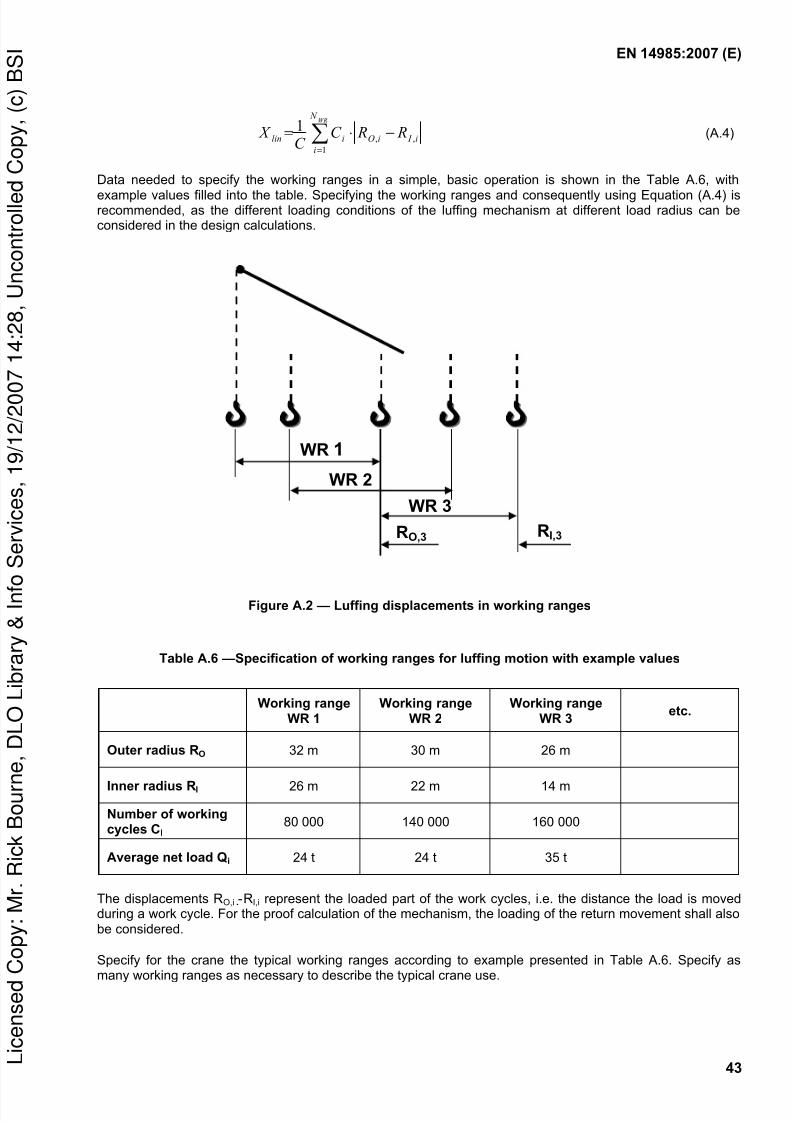
8/9/2019 BSEN14985 Slewing Jib
http://slidepdf.com/reader/full/bsen14985-slewing-jib 45/60
EN 14985:2007 (E)
43
∑=
−⋅=WR N
i
i I iOilin R RC C
X 1
,,
1 (A.4)
Data needed to specify the working ranges in a simple, basic operation is shown in the Table A.6, with
example values filled into the table. Specifying the working ranges and consequently using Equation (A.4) isrecommended, as the different loading conditions of the luffing mechanism at different load radius can beconsidered in the design calculations.
Figure A.2 — Luffing displacements in working ranges
Table A.6 —Specification of working ranges for luffing motion with example values
Working rangeWR 1
Working rangeWR 2
Working rangeWR 3
etc.
Outer radius RO 32 m 30 m 26 m
Inner radius RI 26 m 22 m 14 m
Number of workingcycles CI
80 000 140 000 160 000
Average net load Qi 24 t 24 t 35 t
The displacements RO,i - RI,i represent the loaded part of the work cycles, i.e. the distance the load is movedduring a work cycle. For the proof calculation of the mechanism, the loading of the return movement shall alsobe considered.
Specify for the crane the typical working ranges according to example presented in Table A.6. Specify as
many working ranges as necessary to describe the typical crane use.
RO,3
WR 1
WR 2
WR 3
RI,3
py
y
py
()

8/9/2019 BSEN14985 Slewing Jib
http://slidepdf.com/reader/full/bsen14985-slewing-jib 46/60
EN 14985:2007 (E)
44
For classification of the luffing mechanism, either
a) calculate the average luffing displacement
X l in =
orb) choose the class Dlin for luffing =
(Table A.5)
A.5 Classification of the slewing mechanism
The range that the slew mechanism moves as an average in a working cycle is expressed by an average
angular displacement X ang of the load in the slew direction. This may be classified and chosen according to
Table A.7, or it can be calculated based on the planned operation of the crane.
Basically X ang is the average of the slewing displacements through all the load cycles C. In a simple operation,where in each work cycle the load is moved only once through each slewing sector α i , the X ang is calculatedas follows:
∑=
=
C
i
iang C X
1
1 α (A.5)
If the operation of the slew motion can be grouped to few working ranges (WR) as illustrated in Figure A.3, theaverage slewing displacement can be calculated as follows:
∑=
⋅=WR N
i
iiang C C X
1
1 α (A.6)
Data needed to specify the working ranges in a simple, basic operation is shown in the Table A.7, withexample values filled into the table. Specifying the working ranges and consequently using Equation (A.6) isrecommended, as the different loading conditions of the slewing mechanism at different load radius can beconsidered in the design calculations.
py
y
py
()

8/9/2019 BSEN14985 Slewing Jib
http://slidepdf.com/reader/full/bsen14985-slewing-jib 47/60
EN 14985:2007 (E)
45
Figure A.3 — Slewing displacements and working ranges
Table A.7 —Specification of working ranges for slewing motion with example values
Working rangeWR 1
Working rangeWR 2
Working rangeWR 3
etc.
Average radius Ri 29 m 26 m 20 m
Working sector α αα α i 120° 70° 90°
Specified number ofworking cycles
80 000 140 000 160 000
Average net load Qi 24 t 24 t 35 t
WR 2 , αααα2
Ri
WR 3,
αααα3
WR 1 , αααα1
py
y
py
()

8/9/2019 BSEN14985 Slewing Jib
http://slidepdf.com/reader/full/bsen14985-slewing-jib 48/60
EN 14985:2007 (E)
46
Table A.8 —Classes D of mechanism
Average angular displacement
for design calculationsClass X ang [°]
X ang [radians]
Dang 0 X ang = 11,3 X ang = π/16
Dang 1 X ang = 22,5 X ang = π/8
Dang 2 X ang = 45 X ang = π/4
Dang 3 X ang = 90 X ang = π/2
Dang 4 X ang = 180 X ang = π
Dang 5 X ang = 360 X ang = 2π
The slewing sectors α i represent the loaded part of the work cycles, i.e. the sector the load is moved during a
work cycle. For the proof calculation of the mechanism, the loading condition of the return movement shallalso be considered.
Specify for the crane the typical working ranges according to example presented in Table A.8. Specify asmany working ranges as necessary to describe the typical crane use.
For classification of the slewing mechanism, either
a) calculate the average displacement X ang =
or
b) choose the class Dang for Slewing =
(Table A.8)
py
y
py
()

8/9/2019 BSEN14985 Slewing Jib
http://slidepdf.com/reader/full/bsen14985-slewing-jib 49/60
EN 14985:2007 (E)
47
Annex B (normative)
Load combinations
Table B.1 — Description of load combinations
Load Combinations
Description
A1 and B1 Jib cranes normally lifting an unrestrained grounded load (see EN 13001-2:2004,4.2.2.2.1) together with two other engaged motions selected from those available toproduce maximum loading, without in-service wind and other climatic effects (A1), andwith in-service wind and other climatic effects (B1).
A2 and B2 Jib cranes under normal service conditions having a facility to suddenly release part ofthe hoisted load (see EN 13001-2, 4.2.2.2.1). This action shall be combined with two
other engaged motions selected from those available to produce maximum loading,without in-service wind and other climatic effects (A2), and with in-service wind and otherclimatic effects (B2).
A3 and B3 Jib cranes under normal service conditions accelerating the suspended load (seeEN 13001-2:2004, 4.2.2.4). This action shall be combined with two other engagedmotions selected from those available to produce maximum loading, without in-servicewind and other climatic effects (A3), and with in-service wind and other climatic effects(B3).
A4 and B4 Jib cranes under normal service conditions travelling on an uneven surface (seeEN 13001-2:2004, 4.2.2.3). The resultant loading shall be combined together with twoother engaged motions selected from those available to produce maximum loading,
without in-service wind and other climatic effects (A4), and with in-service wind and otherclimatic effects (B4)
B5 Jib cranes under normal service conditions travelling on an uneven track surface atconstant speed and skewing (see EN 13001-2:2004, 4.2.2.3 and 4.2.3.4) with in-servicewind and other climatic effects.
C1.1 Jib cranes under in-service conditions, hoisting a grounded load under the exceptionalcircumstances depicted in EN 13001-2:2004, 4.2.4.1
C1.2 Jib cranes under in-service conditions, stall load condition according to 5.2.4.
C2 Jib cranes under out-of-service conditions, including out-of-service wind and loads fromother climatic effects.
C3 Jib cranes under test conditions. The hoisting action shall be combined together with twoother engaged motions to produce maximum loading.
C4 to C8 Jib Cranes, where applicable, with gross load in combination with loads such as bufferforces, (C4); tilting forces, (C5); emergency cut-out, (C6); failure of mechanism, (C7) andexcitation of crane foundation, (C8) shall be taken into account.
py
y
py
()
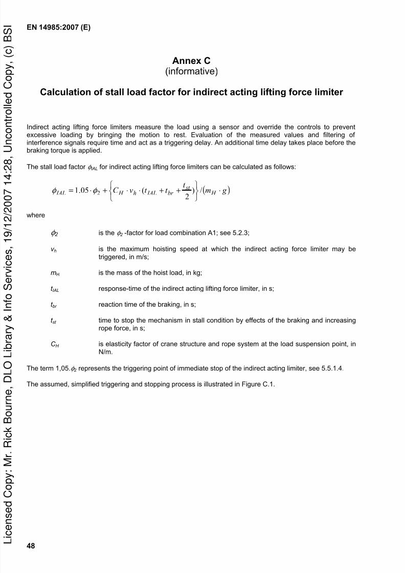
8/9/2019 BSEN14985 Slewing Jib
http://slidepdf.com/reader/full/bsen14985-slewing-jib 50/60
EN 14985:2007 (E)
48
Annex C(informative)
Calculation of stall load factor for indirect acting lifting force limiter
Indirect acting lifting force limiters measure the load using a sensor and override the controls to preventexcessive loading by bringing the motion to rest. Evaluation of the measured values and filtering ofinterference signals require time and act as a triggering delay. An additional time delay takes place before thebraking torque is applied.
The stall load factor φ IAL for indirect acting lifting force limiters can be calculated as follows:
( ) g mt
t t vC H st
br IALh H IAL ⋅
++⋅⋅+⋅= /)
2
(05.1 2φ φ
where
φ 2 is the φ 2 -factor for load combination A1; see 5.2.3;
v h is the maximum hoisting speed at which the indirect acting force limiter may be
triggered, in m/s;
mH is the mass of the hoist load, in kg;
t IAL response-time of the indirect acting lifting force limiter, in s;
t br reaction time of the braking, in s;
t st time to stop the mechanism in stall condition by effects of the braking and increasingrope force, in s;
C H is elasticity factor of crane structure and rope system at the load suspension point, in
N/m.
The term 1,05.φ 2 represents the triggering point of immediate stop of the indirect acting limiter, see 5.5.1.4.
The assumed, simplified triggering and stopping process is illustrated in Figure C.1.
py
y
py
()

8/9/2019 BSEN14985 Slewing Jib
http://slidepdf.com/reader/full/bsen14985-slewing-jib 51/60
EN 14985:2007 (E)
49
t
D
A B C
t stt brt IAL
V
Figure C.1 — Hoist mechanism speed (v) by time (t) at immediate stop with indirect acting lifting forcelimiter
A: triggering happens C: braking is applied
B: braking receives the stopping instruction D: the hoist mechanism has stopped
py
y
py
()

8/9/2019 BSEN14985 Slewing Jib
http://slidepdf.com/reader/full/bsen14985-slewing-jib 52/60
EN 14985:2007 (E)
50
Annex D(normative)
Noise test code for slewing jib cranes
D.1 General
This noise test code specifies all the information necessary to carry out efficiently and under standardizedconditions the determination, declaration and verification of the noise emission characteristics of slewing jibcranes.
Noise emission characteristics include emission sound pressure levels at operator's positions. Thedetermination of these quantities is necessary for:
manufacturers to declare the noise emitted;
comparing the noise emitted by machines in the family concerned;
purpose of noise control at the source at the design stage.
The use of this noise test code ensures reproducibility of the determination of the noise emissioncharacteristics within specified limits determined by the grade of accuracy of the basic noise measurementmethod used. Noise determination methods offered by this standard are:
a calculation method (D.3) to determine the overall noise emitted by the noisiest components of the crane.This method shall be used systematically during the design stage by the manufacturer to ensure that alow noise emission crane is being produced. This method underestimates the actual noise emission valueof the crane when installed at the user's place;
a measurement method (D.4) of the sound pressure level at the operator's and other specified positions.This sound pressure level is strictly speaking not an emission sound pressure level because it includesnot only the crane but also the structure to which the crane is fixed. This method determines two values,one for the work cycle without travelling and, where the crane is designed to travel, another for thetravelling of the crane. For the emission sound pressure level at the operator's positions, both valueshave to be considered. The actual value may be higher than the biggest of them, when there is a situationwhere travelling occurs with other motions at the same time. The latter situation is not covered by thisnoise test code.
The C-weighted peak emission sound pressure levels in slewing jib cranes are typically so low that they donot need to be measured and declared.
D.2 Description of machinery family
This annex is applicable to individual slewing jib cranes, within the scope of this European Standard, fullyassembled in the intended working condition including the fixed load lifting attachment.
py
y
py
()

8/9/2019 BSEN14985 Slewing Jib
http://slidepdf.com/reader/full/bsen14985-slewing-jib 53/60
EN 14985:2007 (E)
51
D.3 Determination of a conventional emission sound pressure level by calculation
D.3.1 Principle of the method
A conventional emission sound pressure level at the operator's positions shall be calculated as the summationof the contributions at each position of the main noise sources present on the crane. These contributions shallbe derived from the sound power levels of these main noise sources as provided by their manufacturer's.
Figure D.1 indicates noise sources and a single operator position for a typical medium sized crane. Dependingon the design of the crane, there could be a number of driver positions including the ground
D.3.2 Calculation
The contribution of a given noise source with A-weighted sound power level LWA is given by the followingequation:
−=
0
lg10 S
S L L WA pA
where
L pA is the resulting A-weighted sound pressure level at the operator's position;
LWA is the A-weighted sound power level of the source, in decibels; reference:1 pW;
S = 2πr 2, where r is the distance between the considered place and the sound source;
S0 = 1 m2
The values of the sound power level of the components to be used in the calculation shall correspond to therated loads and speeds of the crane.
The noise sources to be taken by the calculation are:
hoist mechanism;
slew mechanism;
luff mechanism;
crane travelling mechanisms;
fixed load lifting attachment, when power operated.
The values to be used shall include the noise of the electrical control cubicles and power source.
The typical locations of these noise sources are shown in Figure D.1. The operator is assumed to be in avertical plane containing the sources. For a power operated load lifting attachment the nearest normaloperating distance shall be considered.
The values of the A-weighted sound power levels and the distances r used for the calculations shall be
reported.py
y
py
()

8/9/2019 BSEN14985 Slewing Jib
http://slidepdf.com/reader/full/bsen14985-slewing-jib 54/60

8/9/2019 BSEN14985 Slewing Jib
http://slidepdf.com/reader/full/bsen14985-slewing-jib 55/60
EN 14985:2007 (E)
53
1,741010lg10721,0701,0
)( =+= ⋅⋅total pA L dB
D.4 Emission sound pressure level determination at control stations and other
specified positions by measurement
D.4.1 Measurement method and points
Emission sound pressure level measurements shall be made according to EN ISO 11201 at the followingpositions:
a) The measurements shall be made in or at all control stations
b) Measurements shall also be taken at minimum and maximum jib radius at a height of 1,6 m aboveground level on each working side of the crane. The highest value measured shall be reported anddeclared together with its position.
This measurement also covers the non-fixed operator positions in the case of radio control and positionsspecified for very large cranes (see D.4.2).
During measurement of the crane travelling the measuring point shall be kept stationary.
D.4.2 Case of very large cranes
Those cranes that have an A-weighted emission sound pressure level at the operator’s position higher than85 dB are very large cranes. For such cranes, the determination of sound power is replaced by that ofemission sound pressure levels on a path at 1 m from the surface of the crane and 1,6 m above the ground.Measurement positions on the path shall be spaced so that the difference in A-weighted emission soundpressure levels between adjacent measuring points does not exceed 5 dB. The number of measuring points
will depend on the characteristic of the noise emission. For even distribution of sound pressure levels a lownumber of measuring points may be required. There should, however, be at least one measuring point at eachside of the main components of the crane. The measurement positions shall be recorded and reported.
D.4.3 Installation and mounting conditions
The crane shall be installed in it’s fixed position or on its runway in the condition it is intended to be used,excluding the sound alarm signals which shall be disconnected during the noise measurements.
The mechanisms of the non-fixed load lifting attachments causing noise shall be switched off during the noisemeasurement cycle.
NOTE Noise caused by the non-fixed load lifting attachments is the matter of the manufacturer of the equipment.
D.4.4 Operating conditions
D.4.4.1 General
In all cases, the testing position of the crane for the measurements shall be so selected that the reflections bynearby obstacles and other environmental disturbances are minimized.
The load handled during the work cycles shall be the rated load, but in the case of difficulty in using the ratedload, a load representing the typical loads and having a mass that is at least 50 % of the rated load mass maybe used.
Measurements in enclosed cabins shall be taken with the doors and windows closed and the air-conditioningand/or ventilating system(s) operating at midrange speed if more than two operating speeds are available. If
py
y
py
()

8/9/2019 BSEN14985 Slewing Jib
http://slidepdf.com/reader/full/bsen14985-slewing-jib 56/60
8/9/2019 BSEN14985 Slewing Jib
http://slidepdf.com/reader/full/bsen14985-slewing-jib 57/60
EN 14985:2007 (E)
55
In the calculation method the assumptions made for the calculation, the precise positions of sound sourcesand operator position(s), the values used as sound power input data and the results of the calculations shallbe recorded.
D.7 Information to be reported
The test report shall include the A-weighted emission sound pressure levels and the positions where theywere measured or calculated.
The noise values measured during crane travelling shall be reported separately from the values representingthe specified work cycle, because such values may be more strongly affected by the noise generated in therunways.
In the calculation method the assumptions made for the calculation, the precise positions of sound sourcesand operator(s), the values used as sound power input data and the results of the calculations shall bereported.
D.8 Declaration and verification of noise emission values
The declaration and verification of noise emission values shall be made in accordance withEN ISO 4871.
The noise declaration shall be a dual number declaration as defined in EN ISO 4871 i.e. the measured valueand the measurement uncertainty shall be indicated separately. It shall give the value of the measured A-weighted emission sound pressure level at the operator and other specified positions where this exceeds70 dB; where this level does not exceed 70 dB, this fact shall be indicated.
Both values for the work cycle without travelling (see D.4.4.2) and, where the crane is designed to travel, for
the travelling of the crane (see D.4.4.3) shall be declared.
The noise declaration shall mention explicitly that noise emission values have been obtained in accordancewith this noise test code and indicate the basic standard that has been used i.e. EN ISO 11201. The noisedeclaration shall clearly indicate any deviation(s) from this noise test code and/or from the basic standardused.
For very large cranes (see D.4.2), the values on the path around the crane shall also be declared.
When the noise emission values of an individual crane as determined according to D.4 are verified, themeasurements shall be conducted by using the same mounting, installation and operating conditions as thoseused for the initial determination of noise emission values.
Where slewing jib cranes are constructed on site from sub-assemblies, noise emission measurement and thesubsequent noise emission declaration shall be made after commissioning.
py
y
py
()

8/9/2019 BSEN14985 Slewing Jib
http://slidepdf.com/reader/full/bsen14985-slewing-jib 58/60
EN 14985:2007 (E)
56
Annex ZA(informative)
Relationship between this European Standard and the Essential
Requirements of EU Directive 98/37/EC
This European Standard has been prepared under a mandate given to CEN by the European Commissionand the European Free Trade Association to provide one means of conforming to Essential Requirements ofthe New Approach Directive Machinery 98/37/EC, amended by 98/79/EC.
Once this standard is cited in the Official Journal of the European Communities under that Directive and hasbeen implemented as a national standard in at least one Member State, compliance with the normativeclauses of this standard confers, within the limits of the scope of this standard, a presumption of conformitywith the relevant Essential Requirements of that Directive and associated EFTA regulations.
WARNING: Other requirements and other EU Directives may be applicable to the product(s) falling within thescope of this standard.
py
y
py
()

8/9/2019 BSEN14985 Slewing Jib
http://slidepdf.com/reader/full/bsen14985-slewing-jib 59/60
EN 14985:2007 (E)
57
Bibliography
[1] EN 614-1, Safety of machinery — Ergonomic design principles — Part 1: Terminology and general principles
[2] EN 1050, Safety of machinery — Principles for risk assessment
[3] EN 61000-6-2, Electromagnetic compatibility (EMC) — Part 6-2 Generic standards — Immunity forindustrial environments (IEC 61000-6-2:2005)
[4] EN ISO 1680, Acoustics — Test code for the measurement of airborne noise emitted by rotatingelectrical machinery (ISO 1680:1999)
[5] EN ISO 3744, Acoustics — Determination of sound power levels of noise sources using sound pressure — Engineering method in an essentially free field over a reflecting plane (ISO 3744:1994)
[6] EN ISO 11202:1995, Acoustics — Noise emitted by machinery and equipment — Measurement ofemission sound pressure levels at a work station and at other specified positions — Survey method insitu (ISO 11202:1995)
[7] EN ISO 11203:1995, Acoustics — Noise emitted by machinery and equipment — Determination ofemission sound pressure levels at a work station and at other specified positions from the sound power level (ISO 11203:1995)
[8] EN ISO 11204:1995, Acoustics — Noise emitted by machinery and equipment — Measurement ofemission sound pressure levels at a work station and at other specified positions — Method requiringenvironmental corrections (ISO 11204:1995)
[9] EN ISO 11688-2, Acoustics — Recommended practice for the design of low-noise machinery andequipment — Part 2: Introduction to the physics of low noise design (ISO/TR 11688-2:1998)
[10] ISO 4309, Cranes — Wire ropes — Care, maintenance, installation, examination and discard
[11] ISO 9374-1, Cranes — Information to be provided — Part 1: General
[12] ISO 10245-4:2004, Cranes — Limiting and indicating devices — Part 4: Jib cranes
py
y
py
()

8/9/2019 BSEN14985 Slewing Jib
http://slidepdf.com/reader/full/bsen14985-slewing-jib 60/60
BS EN14985:2007
BSI — British Standards Institution
BSI is the independent national body responsible for preparingBritish Standards. It presents the UK view on standards in Europe and at theinternational level. It is incorporated by Royal Charter.
Revisions
British Standards are updated by amendment or revision. Users ofBritish Standards should make sure that they possess the latest amendments oreditions.
It is the constant aim of BSI to improve the quality of our products and services.We would be grateful if anyone finding an inaccuracy or ambiguity while usingthis British Standard would inform the Secretary of the technical committeeresponsible, the identity of which can be found on the inside front cover.Tel: +44 (0)20 8996 9000. Fax: +44 (0)20 8996 7400.
BSI offers members an individual updating service called PLUS which ensuresthat subscribers automatically receive the latest editions of standards.
Buying standards
Orders for all BSI, international and foreign standards publications should beaddressed to Customer Services. Tel: +44 (0)20 8996 9001.Fax: +44 (0)20 8996 7001. Email: [email protected]. Standards are alsoavailable from the BSI website at http://www.bsi-global.com.
In response to orders for international standards, it is BSI policy to supply theBSI implementation of those that have been published as British Standards,unless otherwise requested.
Information on standards
BSI provides a wide range of information on national, European andinternational standards through its Library and its Technical Help to ExportersService. Various BSI electronic information services are also available which give
details on all its products and services. Contact the Information Centre.Tel: +44 (0)20 8996 7111. Fax: +44 (0)20 8996 7048. Email: [email protected].
Subscribing members of BSI are kept up to date with standards developmentsand receive substantial discounts on the purchase price of standards. For detailsof these and other benefits contact Membership Administration.Tel: +44 (0)20 8996 7002. Fax: +44 (0)20 8996 7001.Email: [email protected].
Information regarding online access to British Standards via British StandardsOnline can be found at http://www.bsi-global.com/bsonline.
Further information about BSI is available on the BSI website athttp://www.bsi-global.com.
Copyright
Copyright subsists in all BSI publications. BSI also holds the copyright, in theUK, of the publications of the international standardization bodies. Except aspermitted under the Copyright, Designs and Patents Act 1988 no extract may bereproduced, stored in a retrieval system or transmitted in any form or by anymeans – electronic, photocopying, recording or otherwise – without prior writtenpermission from BSI.
This does not preclude the free use, in the course of implementing the standard,
y
py
()


![Pillar and wall-mounted slewing jib cranes¸ylesvingkran.pdf · Jib type/design Max. outreach [m] ... Configure a slewing jib crane solution to meet your needs with our Demag Designer](https://img.dokumen.tips/doc/110x75/5b535fa87f8b9ae30b8be950/pillar-and-wall-mounted-slewing-jib-ylesvingkranpdf-jib-typedesign-max-outreach.jpg)