Embed Size (px)
Citation preview

BSD Technical Standard
Division 26: Electrical 04/30/17: Rev2 Page 1 of 21
BSD Technical Standard
Division 26: Electrical
I. PURPOSE
This Technical Standard is a narrative describing Beaverton School District’s (BSD’s) Basis of
Design for electrical systems. The information contained herein shall be used by the Project
Design Team to develop a sustainable and integrated electrical, lighting, and controls system
that is economical to construct, maintain, and operate; that enhances learning by providing a
safe and suitable work environment for staff and students. This Technical Standard shall be used
as part of the BSD’s General Design Standards (comprised of the BSD Educational Specifications
and the BSD Technical Standards).
These Division 26 Technical Standards were developed with the intent of extending the trouble-
free life of equipment, reducing future maintenance problems and addressing energy
conservation as a priority. Within these goals and project budget constraints, electrical
engineering design for BSD projects should comply with the following hierarchy of priorities:
▪ Occupant safety
▪ Program compliance/occupant comfort
▪ Life-cycle cost including maintenance and energy
▪ Initial cost
II. GENERAL
A. DESIGN DOCUMENTS
The District’s assigned numbers shall be used for all labeling. Design assumptions that
define the capabilities of the building shall be documented on the drawings. These
include, but are not limited to: electrical load, lighting power density, assumed hours of
operation, provisions for future expansion (if any).
B. CLOSE-OUT
1. Training
Provide training for appropriate District personnel. Training will review complete
Operations and Maintenance (O&M) Manual, including but not limited to, programming
and setup of any control systems, required maintenance, and troubleshooting, including
contact names and phone numbers for factory support.

BSD Technical Standard
Division 26: Electrical 04/30/17: Rev2 Page 2 of 21
C. SAFETY
1. Electrical Equipment
Secure and limit access to all energized electrical equipment. Electrical equipment and
panels shall be behind closed doors or in non-public access areas.
2. Hazardous Materials
Including, but not limited to, fluorescent lamps and PCB containing transformers,
ballasts and fixtures, must be handled and disposed of in compliance with all applicable
environmental regulations. Notify the Owner and file all required reports upon
discovery of any hazardous materials. All handling or disposal of hazardous materials
must be documented and handled in compliance with all current EPA and Oregon DEQ
requirements and regulations.
3. Outages
A minimum of seven calendar days, in advance, coordinate all electrical service outages
with the District and the power company.
Confirm outage times with BSD Representative, in advance, a minimum of 48 hours.
Plan all work so that the duration of outage is kept to an absolute minimum.
Provide temporary wiring as required in order to maintain continuous service to
occupied portions of the building during business hours.
D. DEMOLITION AND SALVAGE
1. Salvage
BSD has first rights of salvage for equipment and materials removed during
construction. Coordinate project specific details with the BSD Representative.
III. BASIC ELECTRICAL REQUIREMENTS
A. SUPPORTING DEVICES
1. Conduits
Conduits shall be supported within 18” of outlets, boxes, panels, cabinets, and
deflections (current code is 36”). Maximum distance between supports is not to exceed
5’-0” (current code is 10’-0”). Prevent movement and/or sag of junction boxes, pull
boxes, or other conduit terminating housings located above suspended ceilings by
suspending them from appropriate supports or roof structure.
B. POWER
1. Primary
Transformers and power cable for primary feeders over 600V shall be furnished,
installed, connected, and owned by the serving utility company.
BSD Technical Standard
Division 26: Electrical 04/30/17: Rev2 Page 3 of 21
2. Secondary Main
At new installations, provide a cost/benefit analysis comparing a single service at 480V
3-phase versus two services, one at 480V 3-phase and the other at 208V 3-phase. The
desire is to have all transformers located on the utility side of the meters.
a) Single-phase main power is only allowed with BSD Representative
approval.
3. Capacity
Switchgear and main distribution shall be designed and sized for 150% of the code
calculated loads to allow for future expansion in both ampacity and physical capacity.
4. Dry-Type Transformers
Manufacturers: Cutler-Hammer, Siemens, Square D, General Electric
Rating: 480V 3-phase primary; 208/120V 3-phase secondary, KVA rating as required.
Use NEMA Standard TP-1 compliant transformers. Transformer shall be rated for
average 115°C temperature rise above 40°C ambient with 100% of rated nameplate load
connected to the secondary.
Provide mechanical type lugs for conductor terminations.
Mount on a vibration mounting pad suitable for isolating the transformer housing from
building structure. Provide 4” thick, concrete housekeeping pad above adjacent finished
floor for floor-mounted transformers.
5. Back-up Power and Standby Generators
Note: generators should last 96 hours at minimum
a) Diesel Generator System
The following items shall be served by the emergency generator at schools:
▪ Main reception and
Principal’s office
convenience outlet(s)
▪ Custodian’s office
convenience outlet
▪ Kitchen convenience
outlets
▪ Bathroom lighting
▪ Egress/Security
lighting
▪ Exit lights
▪ Common area lights
▪ Gym lights
▪ Fire Alarm systems
▪ Security systems
▪ MDF/Office IDF/phone
systems
▪ Elevator/Elevator(s) on
selective switch on
manual transfer
▪ Emergency Voice/alarm
communications
▪ Recirculation HVAC
fans, not to include
heating or cooling
▪ Ventilation fans
▪ Power exhaust fans
▪ Freezer
▪ Cooler
▪ Fire Sprinkler
Dry-system Air
Compressor
Acceptable Manufacturers: Caterpillar, Kohler, Cummins. UL2200 listed.
BSD Technical Standard
Division 26: Electrical 04/30/17: Rev2 Page 4 of 21
b) Engine
▪ Liquid-cooled diesel
engine
▪ 90 amp hour battery
with rack, cables and 2
amp charger
▪ Coolant heater
▪ Critical exhaust
silencer
▪ Fuel filter and water
separator
▪ Air cleaner and oil
filter with internal
bypass
▪ Low coolant, low oil
pressure, high water
temperature,
overcrank, and
overspeed shut downs
▪ 1.5 HP per KW rating
▪ Thermostatically
controlled block heater
▪ Skid mounted radiator
with blower fan and fan
shroud
▪ Electronic governor
▪ Oil drain extension
▪ Operators Manual
c) Generator
▪ Rotating exciter mounted to generator shaft through brushless rotating diode
system
▪ Class F insulation windings per NEMA MG-1
▪ Static type voltage regulator maximum 15% voltage drop for zero to full load
step
▪ Electronic governor with 0.5% frequency regulation
▪ Analog/digital control panel with AC V/A/Frequency meters with phase
selector switch/emergency stop switch with audible alarm/programmable
engine control and monitoring output
▪ Main line circuit breaker sized to specification
▪ Two-year, on-site parts and labor warranty
Remote alarm annunciator panel for emergency generator shall be located in
the main office and must contain the following alarms at a minimum:
▪ High or low voltage,
AC, and battery
▪ Overcrank overspeed
▪ High or low frequency
▪ Unit not in
“automatic”
▪ Low or pre-low oil
pressure
▪ On utility power
▪ Low water
temperature and level
▪ On generator power
▪ High and pre-high
engine temperature
▪ High, low, critical low
fuel alarms
d) Mounting
Skid mounted with internal vibration isolators mounted on a concrete pad and
seismic rated spring isolators. Seismic Zone 3 rated.
e) Housing
Weather housing with rodent guards and sound attenuated enclosure providing
a noise level at 3’-0” from the machine under full load of 80 dB or less.

BSD Technical Standard
Division 26: Electrical 04/30/17: Rev2 Page 5 of 21
f) Fuel Storage
12 hours of diesel fuel in above ground dual wall storage tank.
g) Transfer Switch
▪ 3-pole contactor type mechanically
latched
▪ Time delay neutral
▪ Automated transfer to generator
power when utility power is
interrupted
▪ Automatic transfer back to utility
power when restored
▪ Adjustable automatic exerciser
▪ Use 4-pole type switch with
grounded generator when generator
backs loads
▪ normally served on more than one
electrical service
6. Testing
Factory testing, field load bank test, and full building load test. Provide a copy of test
report to BSD Representative.
IV. WIRING METHODS
All installations shall meet NECA standards for workmanship. All systems shall be complete and
operable. Architect/Engineer (A/E) is responsible for determining voltage, phase, circuit
ampacity, and number of connections. Wiring shall be in cable tray or conduit unless otherwise
noted. When open wiring is permitted, raceways will be required in insulated walls and other
inaccessible areas. See Appendix A: Category Cabling (5e, 6, 6a) for cable coloring specifications.
All pull boxes, junction boxes, and other enclosures shall be accessible without conflict from
other equipment or trades.
Use keyed switches in corridors and commons areas to control lighting locally. See section
G. WIRING DEVICES for key switches specification.
There shall be no more than six convenience outlets per circuit. Provide a minimum of four
convenience outlet circuits in each classroom alternating between outlets. Classroom outlet
circuits shall not be used in other rooms or corridors.
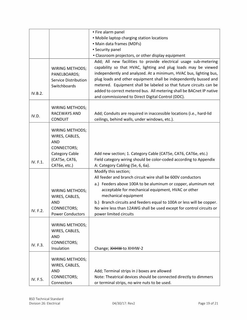
Provide single circuit outlets for the following, and where directed or required for a specific use:
▪ Copiers
▪ Data/telephone intermediate data frames
(IDFs)
▪ Fire alarm panel
▪ Mobile laptop charging station locations
▪Main data frames (MDFs)
▪ Security panel
▪Classroom projectors, or other display
equipment
A. GROUNDING/BONDING NETWORK
1. Ground Rods
Copper clad steel, ¾” diameter, 10’-0” long, tapered point, chamfered top.

BSD Technical Standard
Division 26: Electrical 04/30/17: Rev2 Page 6 of 21
2. Ground Connectors
Hydraulic compression tool applied connectors where possible, or exothermic welding
process connectors. Burndy, Thomas & Betts, Cadweld.
3. Equipment Grounding Conductor
Install continuous equipment grounding conductor, code size minimum, in all raceway
systems.
4. Telecommunications Bonding Backbone (TBB)
Provide a TBB. The Telecommunications Main Grounding Busbar (TMGB) serves as a
dedicated extension of the building ground electrode system at the main service
equipment room. TMGB shall be bonded with 6AWG or larger stranded copper cable to
the Telecommunications Grounding Busbar (TGB) at each Telecommunications Frame
Room. At each frame room, provide TGB: ¼” thick by 4” high by 10” long copper ground
bar with insulators, Harger, Erico/Cadweld, or equal approved. All racks, ladder rays, and
conduit shall be grounded with a minimum of 6AWG copper conductor to TGB.

BSD Technical Standard
Division 26: Electrical 04/30/17: Rev2 Page 7 of 21
5. Protection
Where exposed, protect ground electrode conductor in rigid PVC conduit. Do not use
metal conduit for grounding electrode conductor protection.
6. Remodels, Retrofits, and Additions
Evaluate existing grounding and upgrade existing grounding electrode system at main
service and dry-type transformers, if necessary, to meet current code requirements.
Include re-bonding of main service ground bus to new ground rods.
7. Extension
The Contractor shall extend existing grounding electrode systems and equipment
grounding systems.
B. PANELBOARDS
1. Manufacturers
Square D, General Electric, Siemens, Cutler-Hammer. Match manufacturer and breaker
style with existing panelboards where applicable.
2. Service Distribution Switchboards
Freestanding dead front NEMA 1 enclosure. Fuses shall not be used. All main service
switchgear shall be equipped with circuit breakers fully-rated for available fault current.
Plated copper busbars. Provide fully-rated integrated equipment rating greater than the
available fault current. Compression-type lugs rated for both aluminum and copper
conductors.
All new facilities to provide electrical usage sub-metering capability so that HVAC,
lighting and plug loads may be viewed independently and analyzed. At a minimum,
HVAC bus, lighting bus, plug loads and other equipment shall be independently bussed
and metered. Equipment shall be labeled so that future circuits can be added to correct
metered bus. All metering shall be BACnet IP native and commissioned to Direct Digital
Control (DDC).
3. Branch Circuit Panelboards
Bolt on circuit breaker type. Fuses shall not be used. Plated copper busbars. Provide
fully-rated integrated equipment. UL series rating is allowable if all upstream panels,
including the main service, are installed under this Contract. Compression-type lugs
rated for both aluminum and copper conductors. Provide double hinge covers. Key all
branch panels alike. Provide 20% or more spare circuit capacity for future expansion.
4. Expansion
Where distribution equipment, switchboards, panel boards, or control panels are
installed, it is required that Electrical Metallic Tubing (EMT), Intermediate Metal Conduit
BSD Technical Standard
Division 26: Electrical 04/30/17: Rev2 Page 8 of 21
(IMC), or Galvanized Rigid Conduit (GRC) raceways be installed for a minimum of 5’-0”
out of each piece of equipment.
Provide two additional ¾” and two additional 1” spare conduits from each panel board
to accessible space above and as applicable below panel board for future expansion.
C. OVERCURRENT PROTECTIVE DEVICES
1. Fuses
Dual element, time delay, current limiting, nonrenewable, rejection feature. UL Classes
RK1 and L. Provide with indicator window to show when fuse is blown. Cooper-
Bussmann, Ferraz Shawmut, Littelfuse, or approved equal.
2. Molded Case Circuit Breakers
Cutler-Hammer, General Electric, Siemens, Square D. Adjustable magnetic trip breakers
for motor and compressor loads greater than 100A. Bolt-in style only.
D. RACEWAYS AND CONDUITS
All conduits shall be installed in a concealed manner where possible and shall be
installed parallel to the lines of the building. All conduits shall be a minimum of ¾". Any
exposed conduits shall be installed parallel or at right angles to the building walls or
floors. All exposed conduits shall be securely fastened in place on maximum 5’-0”
intervals for ¾” through 2 ½” nominal sizes.
Runs between junction boxes shall not contain more than the equivalent of three 90°
bends. (No more than 270° total in bends.) Conduit bends shall be made with
appropriate tools of proper size; radius of bends shall be at least six times the diameter
of the conduit.
Conduits are required in inaccessible locations (i.e., hard-lid ceilings, behind walls, under
windows, etc.).
1. Underground
PVC Schedule 40 conduit shall be used for all underground installations. Where installed
in concrete, provisions shall be made to assure a minimum cover of 2” of concrete.
Where installed underground, a minimum of 18” of cover shall be provided. PVC conduit
shall transition with a 90° GRC bend where it emerges from the ground or concrete in all
locations in which it is installed.
2. Dry, Protected Locations
GRC, IMC, EMT. If subject to movement or vibration, use flexible metallic conduit. All
flexible conduits will not exceed 6’-0” in length and shall be used only in areas where
vibrations and/or expansion joints are present.
BSD Technical Standard
Division 26: Electrical 04/30/17: Rev2 Page 9 of 21
3. Damp Locations
Conduit and related equipment must be rated and suitable for the application. Use GRC
or IMC for areas subject to mechanical damage. If subject to movement or vibration,
humidity, water spray, or oil spray, use PVC coated flexible metallic conduit. Sealtite, or
equal, shall be used where flexible conduit connections are required and at connections
to all motorized equipment and motors.
4. Exposed Work in Finished Spaces
Use metallic raceway in all applications. Under no circumstances shall low-voltage cable
bundles be hung from existing electrical conduit systems.
5. Conduit Bodies
Conduit bodies are allowed for feeders and branch circuits less than or equal to 100A
and for signal cabling not related to data communications.
6. Tele-Power Poles
Use aluminum construction, two-compartment poles with minimum thickness of 0.05”.
Wiremold NP600 series, or equal.
7. Conduit Installation
Bushings and connectors shall be plastic insulated, lined, 105°C rated. A bushing shall be
used where conduit enters a panel box.
All heavy wall conduits shall have two locknuts and a bushing at each termination outlet
box, junction box, etc., except where terminated in a threaded hub. Fittings on EMT
shall be set screw type with an insulated throat.
Expansion fittings shall be provided at all conduits across the building expansion joints.
Fittings shall be Type “AX” or “TX” as made by O-Z Gedney Appleton Group, or equal.
Provide copper bonding jumper at each expansion fitting.
E. BOXES
All pull boxes, junction boxes, and other enclosures shall be accessible without conflict
from other equipment or trades. Pull boxes and junction boxes shall be installed where
required to facilitate wire installation.
All switch, pull, junction boxes, and other enclosures shall be hot dipped galvanized,
concrete tight, with interlocking ring.
Avoid proximity to heat ducts and/or steam lines. All conduits shall clear ducts or lines
and their coverings by a minimum of 6”.

BSD Technical Standard
Division 26: Electrical 04/30/17: Rev2 Page 10 of 21
1. Interior Outlet
▪ One-piece boxes and one-piece device covers are required
▪ Minimum box sizes: Galvanized steel, 4” square, 1½” deep
▪ Signal system outlets’ minimum box size: 4” square, 2⅛” deep
2. Floor Boxes
Limit use of floor boxes for specific applications only. All floor boxes shall be code-
approved metal construction, with gasketed metal covers, flush with floor grade (even
in use). No plastic boxes or components. Wiremold Omnibox Series, Hubbell Steel with
adjustable collars and frames, or approved by BSD Representative. Minimum floor box
requirements: 3 7/16” deep with 1” factory knockouts.
3. Weatherproof Outdoor Outlet
Corrosion-resistant, cast metal, threaded conduit entry. Corrosion-resistant, cast metal,
device covers, gasketed.
4. Large Junction and Pull
Painted steel, welded seams, screw on covers.
5. Vaults and In-Ground Boxes
Vaults and in-ground boxes shall have the load bearing capacity to support riding lawn
mowers and similar ground-keeping equipment in all locations.
F. WIRES, CABLES, AND CONNECTORS
1. Category Cable (CAT5e, CAT6, CAT6e, etc.)
Field category wiring should be color-coded according to Appendix A: Category Cabling
(5e, 6, 6a).
2. Power Conductors
All feeder and branch circuit wire shall be 600V conductors
a) Feeders above 100A to be aluminum or copper, aluminum not
acceptable for mechanical equipment, HVAC or other mechanical equipment
b) Branch circuits and feeders equal to 100A or less will be copper
No wire less than 12AWG shall be used except for control circuits or power
limited circuits
(1) Wire sizes 12AWG and larger shall be stranded
(2) There shall be no shared neutrals in any multi-wire branch
circuits
3. Insulation
THHN, THWN or XHHW-2. Minimum 90°C insulated rating for feeders and branch
circuits.

BSD Technical Standard
Division 26: Electrical 04/30/17: Rev2 Page 11 of 21
4. MC Cable
a) Use only for branch circuits within a room space with accessible ceiling
b) Not acceptable in kitchen or other wet environments
c) High strength galvanized steel of flexible armor, no aluminum
d) No conductors larger than 10AWG
e) There shall be no shared neutrals in any multi-wire branch circuits
f) Not acceptable under windows due to inaccessible replacement
5. Connectors
a) Quick push-in wire connectors are prohibited
18AWG - 8AWG spring connector wire nuts to be used
Terminal strips in J boxes are allowed
Note: Theatrical devices should be connected directly to dimmers or terminal strips, no
wire nuts to be used.
6. Splices, Taps, and Terminations
All splices, taps, and terminations shall be made in outlet, junction, or pull boxes. Wire
to 8AWG shall be spliced using spring connector wire nuts. 6AWG and larger, use indent
compression or split bolt connectors for all conductors. Splices 6AWG and larger shall be
insulated to voltage rating of feeder or circuit. Splices shall not be permitted in
automation input and output wiring.
G. WIRING DEVICES
Manufacturers: Hubbell, Pass & Seymour, and Leviton
Color: Gray for all devices
Wall Switches: Specification Grade, Toggle type, 20A, 120/277V
Key Switches: Specification Grade, Pass & Seymour1 only for key standardization
Receptacles: Specification Grade, Duplex 20A, 125V, 2-pole, 3-wire grounding
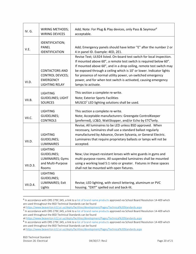
Note: For Plug & Play devices, only Pass & Seymour acceptable.
Ground Fault Circuit Interrupter (GFCI) Receptacle: Specification Grade, Feed-through
type, 20A, 125VAC
Finish Plates: Type 302 stainless steel, satin finish, beveled edge
H. CIRCUIT AND MOTOR DISCONNECTS
Provide disconnect switch in sight of each motor, clearly labeled with circuit and panel
identified. Motor disconnects for overhead doors shall be within 24” of motor.
Manual Motor Starters: Square D, Class 2510, or equal
Safety Switches: Heavy Duty, Class R fuse type
1 In accordance with ORS 279C.345, a link to a list of brand name products approved via School Board Resolution 14-409 which
are used throughout the BSD Technical Standards can be found
at:https://www.beaverton.k12.or.us/depts/facilities/development/Pages/Technical%20Standards.aspx

BSD Technical Standard
Division 26: Electrical 04/30/17: Rev2 Page 12 of 21
V. IDENTIFICATION
A. ENGRAVED LABELS
Engraved labels shall be plastic laminate, black with white core. Install engraved label on
each major unit of electrical equipment, including disconnects, services, distribution
panels, and branch panel boards, main and satellite control panels of each signal
system. Install engraved label on the inside of flush panels, visible when the door is
opened. Minor components such as relays, contactors, time switches, override switches,
etc., do not need to be engraved, but must be clearly labeled.
B. RECEPTACLES AND SWITCHES
On the finish plate, use a label, or legibly write with indelible ink on the back, the circuit
to which each device is connected.
C. JUNCTION AND PULL BOXES
On the cover, use a label, or legibly write with indelible ink, the panel number, circuit
number and voltage for each box.
D. UNDERGROUND UTILITY MARKERS
Use inert polyethylene plastic ribbon, 6” wide by 4 mils thick. Install continuous tape, 6”
to 8” below finish grade, for each exterior underground raceway. Provide trace wire
with all underground conduits.
E. PANEL IDENTIFICATION
Label shall identify panel, voltage, and electrical source. Each electrical panel ID should
start with number where "2" will indicate 208/120V system and "4" will indicate
480/277V system. Example: 2A4/XFMR-T1/MDP4 208/120V identifies 208/120V Panel
2A4, fed from XFMR-T1, fed from MDP4. Emergency panels should have letter "E" after
the number 2 or 4 in panel ID. Example: 4ED, 2E1.
F. BRANCH CIRCUIT SCHEDULES
Schedules shall be typewritten with separate columns for odd and even numbers, using
final building room numbers and identifications. The A/E shall provide a list and drawing
which cross-references the room numbers originally used on all plans and drawings with
the final room numbers assigned by the District.
G. ONE LINE DIAGRAM
Contractor to supply laminated one-line diagram showing disconnects with Record
Drawings for posting in main electrical room.
VI. CONTACTORS AND CONTROL DEVICES
See Division 23: HVAC for Motors and Variable Frequency Drives
BSD Technical Standard
Division 26: Electrical 04/30/17: Rev2 Page 13 of 21
A. CONTACTORS/RELAYS
Lighting contactors and relays, electrically operated mechanically held. ASCO, Cutler
Hammer, Siemens, Square D, or equal.
B. TIME SWITCHES
Seven day, 24 hours, digital astronomical time clock with automatic adjustment for
daylight savings, holiday schedule, and leap year. LCD display. Battery backup to retain
schedules. Intermatic, or equal.
C. PHOTOELECTRIC SWITCHES
120VAC, 1800VA, adjustable light level slide. Intermatic, Paragon, TORK.
D. EMERGENCY LIGHTING RELAY
UL924 listed. On-board test switch for local inspection. If mounted above 60”, a remote
test switch is required below 60”. If mounted above 60”, and in a drop ceiling, remote
test switch may be exposed through a ceiling which is 10’ or lower. Indicator lights for
presence of normal utility power, un-switched emergency power, and for when test
switch is activated, causing emergency lamps to activate.
VII. LIGHTING GUIDELINES
A. LIGHT LEVELS
Light levels in all spaces shall be designed to be in compliance with Illuminating
Engineering Society of North America (IESNA) guidelines and to meet NFPA 101
standards.
B. LIGHT SOURCES
Light sources should be evaluated on the basis of energy efficiency, lamp life, light
quality, control capability, initial cost, ease of maintenance, and warranty.
1. General Lighting Needs
Light Emitting Diodes (LED) lighting shall be used as the basis of design for all new and
remodel projects, excluding special use lighting as required.
▪ LED light fixtures should be DLC, IESNA, and UL listed luminaries
▪ LED light fixtures should be Energy Star rated
▪ 100 lumens/watt minimum
▪ LED Fixtures shall be dimmable 0-10V, DMX or ACN
▪ Drivers should be easily replaceable; for fixtures in hard to reach areas, drivers shall be
remote, and located in accessible area approved by BSD representative
▪ Minimum 5-year warranty
▪ Approved manufacturers: Acuity/Lithonia, Eaton/Cooper Industries, ETC or Philips

BSD Technical Standard
Division 26: Electrical 04/30/17: Rev2 Page 14 of 21
2. Exterior Sports Facilities
MUSCO2 LED lighting solutions shall be used.
3. Fluorescent
The majority of lighting in BSD buildings are currently fluorescent troffer systems. These
systems will continue to be supported and may be installed in retrofit applications for
small projects if necessary; will not be approved for new construction.
Fluorescent lamps shall have the following:
General Lighting:
▪ Color rendering index (CRI) of greater than 80
▪ Color temperature of 3500K
Lighting in Production Spaces:
▪ Color rendering index (CRI) of greater than 90
▪ Color temperature of 2700-3000K
Acceptable Fluorescents
a) Compact fluorescents (CFL)
▪ CFL shall not be used for screw type bases.
b) T8
▪ 4’-10’
▪ The lamp/ballast combination in T8 luminaires shall meet the CEE
(Consortium for Energy Efficiency) specification
▪ LED TLED retrofit troffer lamps are currently not acceptable in the District
due to safety concerns
c) T5 and T5HO
▪ May use T5 and T5 HO only for existing conditions; not to be used for
new construction.
4. Ballasted Fixtures
When necessary, ballasted fixtures shall be High Power Factor, and less than 20% total
harmonic distortion (THD), and have Class P thermal protection.
C. CONTROLS
For new construction, WattStopper Digital Lighting Management (DLM) shall be the
basis of design, except for rooms such as custodial closets, or rooms requiring special
lighting controls such as theaters, sports fields and other presentation spaces.
Acceptable manufacturers WattStopper, Acuity, and Eaton.
2 In accordance with ORS 279C.345, a link to a list of brand name products approved via School Board Resolution 14-409 which
are used throughout the BSD Technical Standards can be found
at:https://www.beaverton.k12.or.us/depts/facilities/development/Pages/Technical%20Standards.aspx

BSD Technical Standard
Division 26: Electrical 04/30/17: Rev2 Page 15 of 21
1. Switches
Switches shall be located in the space that they control. Control switches (3-way,
presets, etc.) shall be provided at all entrances to space. Switches shall be located by
each of the doors. Switches in corridors and public spaces shall be keyed switches:
compatible with Pass & Seymour3 only, momentary contact switch key for heavy-duty
locking switch, 500K, to provide District-wide key standardization.
Classroom luminaires shall have dimmable control.
The row of lights closest to the white board/projection screen shall be capable of being
switched off/dimmed independently of the classroom lighting. The remaining classroom
lighting shall be able to be dimmable during video instruction.
2. Occupancy Sensors
Occupancy sensors shall be used to control lighting in classrooms, restrooms, corridors,
gyms, multi-purpose rooms, cafeterias, and small offices. Occupancy sensors shall
provide complete coverage of area to prevent nuisance OFFs even when the only
activity is writing on a desktop or typing at a computer keyboard. Occupancy sensor
circuits shall be wired to allow OFF override of the lighting in the area. The occupancy
sensor system shall be designed to have no effect on power quality or ballast inrush
current. Occupancy sensors and their related relays shall incorporate "zero-crossing
circuitry.” BSD has standardized WattStopper 4 brand of occupancy sensors.
a) Classrooms
Two dual technology occupancy sensors shall be used. Sensors shall be set to
time-out after 10 minutes of no activity. To include areas such as music and
other such teaching spaces.
b) Restrooms
Multi-stall restrooms shall use ultrasonic technology sensors to detect
occupancy inside stalls and around corners. Other technology only with BSD
approval. Restroom occupancy sensors should be set to time-out after 15
minutes.
3 In accordance with ORS 279C.345, a link to a list of brand name products approved via School Board Resolution 14-409 which
are used throughout the BSD Technical Standards can be found
at:https://www.beaverton.k12.or.us/depts/facilities/development/Pages/Technical%20Standards.aspx 4 In accordance with ORS 279C.345, a link to a list of brand name products approved via School Board Resolution 14-409 which
are used throughout the BSD Technical Standards can be found
at:https://www.beaverton.k12.or.us/depts/facilities/development/Pages/Technical%20Standards.aspx
BSD Technical Standard
Division 26: Electrical 04/30/17: Rev2 Page 16 of 21
c) Gyms and High Ceiling Areas
Passive Infrared (PIR) sensors shall be used in high ceiling areas per
manufacture’s installation requirements. Wire guards are required to protect
sensors from projectiles in all installations
d) Small Offices and Single Stall Restrooms
Wall switch occupancy sensors are acceptable for use in small offices and single
stall restrooms if the sensors have a clear view of the space. The occupancy
sensor shall control the run time for restroom exhaust fans and be set to time-
out after five minutes.
3. Daylight Harvesting
Daylight harvesting controls shall be incorporated into the lighting controls design
where there is a significant contribution to the lighting from daylight. Sensor set points
should be selected to maintain appropriate light levels and incorporate a large enough
dead band to prevent cycling on days with partial cloud cover.
4. Lighting Control Panels
Lighting control panels shall be used to control egress lighting, lighting in commons
areas, lighting in kitchens, and parking lot and exterior building lighting. The lighting
control panel shall be BACnet IP native, coordinate with Division 27: Communications &
Technology Technical Standards. The lighting control panel shall be integrated with the
building security and Fire Alarm System. The lighting control panel shall be programmed
per District requirements, see Control Matrix. Obtain schedule from BSD
Representative. Lighting control panel shall allow over-ride via remote input.
Acceptable manufacturers: Greengate ControlKeeper (preferred), LC&D, WattStopper,
and/or Echo by ETC 5only.
a) Intrusion Alarm and Lighting Control Integration (see also Division 28:
Electronic Safety & Security) see Control Matrix
b) Egress Lighting
The control parameters for egress lighting are as follows:
(1) Power Outage
All lighting fails to the ON position.
(2) Occupied Building
Egress lights will be turned ON when building is occupied (security disarmed) if
occupancy sensors do not turn lights on in occupied space.
5 In accordance with ORS 279C.345, a link to a list of brand name products approved via School Board Resolution 14-409 which
are used throughout the BSD Technical Standards can be found
at:https://www.beaverton.k12.or.us/depts/facilities/development/Pages/Technical%20Standards.aspx
BSD Technical Standard
Division 26: Electrical 04/30/17: Rev2 Page 17 of 21
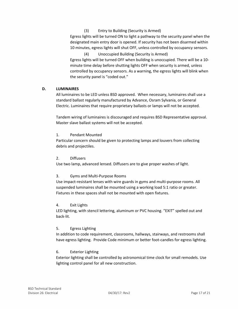
(3) Entry to Building (Security is Armed)
Egress lights will be turned ON to light a pathway to the security panel when the
designated main entry door is opened. If security has not been disarmed within
10 minutes, egress lights will shut OFF, unless controlled by occupancy sensors.
(4) Unoccupied Building (Security is Armed)
Egress lights will be turned OFF when building is unoccupied. There will be a 10-
minute time delay before shutting lights OFF when security is armed, unless
controlled by occupancy sensors. As a warning, the egress lights will blink when
the security panel is “coded out.”
D. LUMINAIRES
All luminaires to be LED unless BSD approved. When necessary, luminaires shall use a
standard ballast regularly manufactured by Advance, Osram Sylvania, or General
Electric. Luminaires that require proprietary ballasts or lamps will not be accepted.
Tandem wiring of luminaires is discouraged and requires BSD Representative approval.
Master slave ballast systems will not be accepted.
1. Pendant Mounted
Particular concern should be given to protecting lamps and louvers from collecting
debris and projectiles.
2. Diffusers
Use two lamp, advanced lensed. Diffusers are to give proper washes of light.
3. Gyms and Multi-Purpose Rooms
Use impact-resistant lenses with wire guards in gyms and multi-purpose rooms. All
suspended luminaires shall be mounted using a working load 5:1 ratio or greater.
Fixtures in these spaces shall not be mounted with open fixtures.
4. Exit Lights
LED lighting, with stencil lettering, aluminum or PVC housing. “EXIT” spelled out and
back-lit.
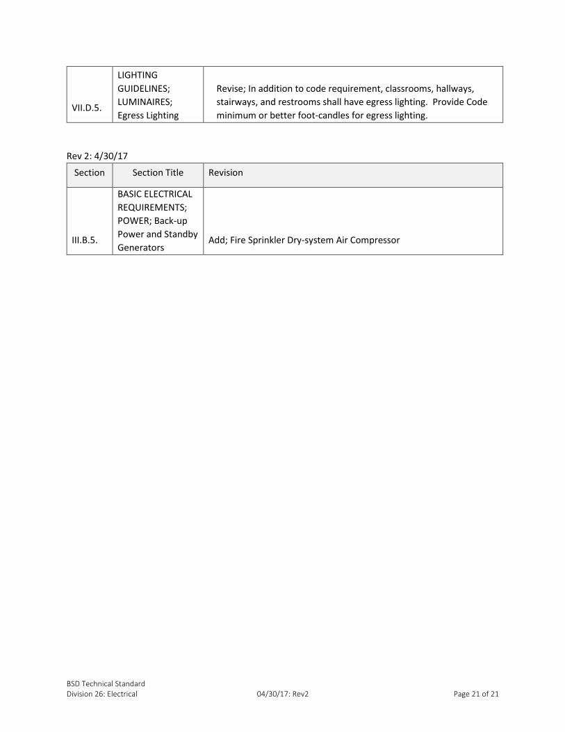
5. Egress Lighting
In addition to code requirement, classrooms, hallways, stairways, and restrooms shall
have egress lighting. Provide Code minimum or better foot-candles for egress lighting.
6. Exterior Lighting
Exterior lighting shall be controlled by astronomical time clock for small remodels. Use
lighting control panel for all new construction.

BSD Technical Standard
Division 26: Electrical 04/30/17: Rev2 Page 18 of 21
Revision History
Rev 1
Section Section Title Revision
III.B.5.
BASIC ELECTRICAL
REQUIREMENTS;
POWER; Back-up
Power and Standby
Generators Add; Note: generators should last 96 hours at minimum
III.B.5.a)
BASIC ELECTRICAL
REQUIREMENTS;
POWER; Back-up
Power and Standby
Generators; Diesel
generator system
Add to generator;
▪ Main reception and Principal’s office convenience outlet(s)
▪ Custodian’s office convenience outlet
▪ Kitchen convenience outlets
▪ Common area lights
▪ Gym lights
▪ MDF/Office IDF/phone systems
▪ Elevator/Elevator(s) on selective switch on manual transfer
▪ Emergency Voice/alarm communications
▪ Recirculation HVAC fans, not to include heating or cooling
▪ Ventilation fans
▪ Power exhaust fans
▪ Freezer
▪ Cooler
IV. WIRING METHODS
Add; See Appendix A: Category Cabling (5e, 6, 6a) for cable coloring
specifications.
IV. WIRING METHODS
¶3; this moved to IV.F.4. and Modified;
a) Use only for branch circuits within a room space with
accessible ceiling
b) Not acceptable in kitchen or other wet environments
c) High strength galvanized steel of flexible armor, no aluminum
d) No conductors larger than 10AWG
e) There shall be no shared neutrals in any multi-wire branch
circuits
f) Not acceptable under windows due to inaccessible
replacement
IV. WIRING METHODS
Add, for keyed switches; See section
G. WIRING DEVICES for key switches specification.
IV.
WIRING METHODS
¶4; add; Provide single circuit outlets for the following, and where
directed or required for a specific use:
▪ Copiers
▪ Data/telephone intermediate data frames (IDFs)
BSD Technical Standard
Division 26: Electrical 04/30/17: Rev2 Page 19 of 21
▪ Fire alarm panel
▪ Mobile laptop charging station locations
▪ Main data frames (MDFs)
▪ Security panel
▪ Classroom projectors, or other display equipment
IV.B.2.
WIRING METHODS;
PANELBOARDS;
Service Distribution
Switchboards
Add; All new facilities to provide electrical usage sub-metering
capability so that HVAC, lighting and plug loads may be viewed
independently and analyzed. At a minimum, HVAC bus, lighting bus,
plug loads and other equipment shall be independently bussed and
metered. Equipment shall be labeled so that future circuits can be
added to correct metered bus. All metering shall be BACnet IP native
and commissioned to Direct Digital Control (DDC).
IV.D.
WIRING METHODS;
RACEWAYS AND
CONDUIT
Add; Conduits are required in inaccessible locations (i.e., hard-lid
ceilings, behind walls, under windows, etc.).
IV. F.1.
WIRING METHODS;
WIRES, CABLES,
AND
CONNECTORS;
Category Cable
(CAT5e, CAT6,
CAT6e, etc.)
Add new section; 1. Category Cable (CAT5e, CAT6, CAT6e, etc.)
Field category wiring should be color-coded according to Appendix
A: Category Cabling (5e, 6, 6a).
IV. F.2.
WIRING METHODS;
WIRES, CABLES,
AND
CONNECTORS;
Power Conductors
Modify this section;
All feeder and branch circuit wire shall be 600V conductors
a.) Feeders above 100A to be aluminum or copper, aluminum not
acceptable for mechanical equipment, HVAC or other
mechanical equipment
b.) Branch circuits and feeders equal to 100A or less will be copper.
No wire less than 12AWG shall be used except for control circuits or
power limited circuits
IV. F.3.
WIRING METHODS;
WIRES, CABLES,
AND
CONNECTORS;
Insulation Change; XHHW to XHHW-2
IV. F.5.
WIRING METHODS;
WIRES, CABLES,
AND
CONNECTORS;
Connectors
Add; Terminal strips in J boxes are allowed
Note: Theatrical devices should be connected directly to dimmers
or terminal strips, no wire nuts to be used.
BSD Technical Standard
Division 26: Electrical 04/30/17: Rev2 Page 20 of 21
IV. G. WIRING METHODS;
WIRING DEVICES
Add; Note: For Plug & Play devices, only Pass & Seymour6
acceptable.
V.E.
IDENTIFICATION;
PANEL
IDENTIFICATION
Add; Emergency panels should have letter "E" after the number 2 or
4 in panel ID. Example: 4ED, 2E1.
VI.D.
CONTACTORS AND
CONTROL DEVICES;
EMERGENCY
LIGHTING RELAY
Revise Text; UL924 listed. On-board test switch for local inspection.
If mounted above 60”, a remote test switch is required below 60”.
If mounted above 60”, and in a drop ceiling, remote test switch may
be exposed through a ceiling which is 10’ or lower. Indicator lights
for presence of normal utility power, un-switched emergency
power, and for when test switch is activated, causing emergency
lamps to activate.
VII.B.
LIGHTING
GUIDELINES; LIGHT
SOURCES
This section a complete re-write.
Note; Exterior Sports Facilities
MUSCO7 LED lighting solutions shall be used.
VII.C.
LIGHTING
GUIDELINES;
CONTROLS
This section a complete re-write.
Note; Acceptable manufacturers: Greengate ControlKeeper
(preferred), LC&D, WattStopper, and/or Echo by ETC8only.
VII.D.
LIGHTING
GUIDELINES;
LUMINAIRES
Revise; All luminaires to be LED unless BSD approved. When
necessary, luminaires shall use a standard ballast regularly
manufactured by Advance, Osram Sylvania, or General Electric.
Luminaires that require proprietary ballasts or lamps will not be
accepted.
VII.D.3.
LIGHTING
GUIDELINES;
LUMINAIRES; Gyms
and Multi-Purpose
Rooms
New; Use impact-resistant lenses with wire guards in gyms and
multi-purpose rooms. All suspended luminaires shall be mounted
using a working load 5:1 ratio or greater. Fixtures in these spaces
shall not be mounted with open fixtures.
VII.D.4.
LIGHTING
GUIDELINES;
LUMINAIRES; Exit
Lights
Revise; LED lighting, with stencil lettering, aluminum or PVC
housing. “EXIT” spelled out and back-lit.
6 In accordance with ORS 279C.345, a link to a list of brand name products approved via School Board Resolution 14-409 which
are used throughout the BSD Technical Standards can be found
at:https://www.beaverton.k12.or.us/depts/facilities/development/Pages/Technical%20Standards.aspx 7 In accordance with ORS 279C.345, a link to a list of brand name products approved via School Board Resolution 14-409 which
are used throughout the BSD Technical Standards can be found
at:https://www.beaverton.k12.or.us/depts/facilities/development/Pages/Technical%20Standards.aspx 8 In accordance with ORS 279C.345, a link to a list of brand name products approved via School Board Resolution 14-409 which
are used throughout the BSD Technical Standards can be found
at:https://www.beaverton.k12.or.us/depts/facilities/development/Pages/Technical%20Standards.aspx
BSD Technical Standard
Division 26: Electrical 04/30/17: Rev2 Page 21 of 21
VII.D.5.
LIGHTING
GUIDELINES;
LUMINAIRES;
Egress Lighting
Revise; In addition to code requirement, classrooms, hallways,
stairways, and restrooms shall have egress lighting. Provide Code
minimum or better foot-candles for egress lighting.
Rev 2: 4/30/17
Section Section Title Revision
III.B.5.
BASIC ELECTRICAL
REQUIREMENTS;
POWER; Back-up
Power and Standby
Generators Add; Fire Sprinkler Dry-system Air Compressor