Embed Size (px)
DESCRIPTION
BSC6900 Configuration Principle(Global)
Citation preview

SRAN8.0&GBSS15.0&RAN15.0 BSC6900
Configuration Principles (Global)
Issue 09
Date 2015-07-27
HUAWEI TECHNOLOGIES CO., LTD.

Copyright © Huawei Technologies Co., Ltd. 2015. All rights reserved.
No part of this document may be reproduced or transmitted in any form or by any means without prior writtenconsent of Huawei Technologies Co., Ltd. Trademarks and Permissions
and other Huawei trademarks are trademarks of Huawei Technologies Co., Ltd.All other trademarks and trade names mentioned in this document are the property of their respective holders. NoticeThe purchased products, services and features are stipulated by the contract made between Huawei and thecustomer. All or part of the products, services and features described in this document may not be within thepurchase scope or the usage scope. Unless otherwise specified in the contract, all statements, information,and recommendations in this document are provided "AS IS" without warranties, guarantees or representationsof any kind, either express or implied.
The information in this document is subject to change without notice. Every effort has been made in thepreparation of this document to ensure accuracy of the contents, but all statements, information, andrecommendations in this document do not constitute a warranty of any kind, express or implied.
Huawei Technologies Co., Ltd.Address: Huawei Industrial Base
Bantian, LonggangShenzhen 518129People's Republic of China
Website: http://www.huawei.com
Email: [email protected]
Issue 09 (2015-07-27) Huawei Proprietary and ConfidentialCopyright © Huawei Technologies Co., Ltd.
i

Contents
1 Change History..............................................................................................................................1
2 Introduction....................................................................................................................................62.1 Overview........................................................................................................................................................................72.2 Version Difference.........................................................................................................................................................72.2.1 BSC6900 GSM Version Difference............................................................................................................................72.2.2 BSC6900 UMTS Version Difference..........................................................................................................................82.2.3 BSC6900 GU Version Difference...............................................................................................................................8
3 Application Overview................................................................................................................10
4 Product Configurations..............................................................................................................154.1 BSC6900 GSM Product Configurations.......................................................................................................................164.1.1 Hardware Capacity License Configurations..............................................................................................................164.1.2 Service Processing Units Configurations..................................................................................................................174.1.3 Interface Boards Configurations................................................................................................................................244.1.4 Clock Boards Configurations....................................................................................................................................294.1.5 General Principles of Configuring Boards in Slots...................................................................................................304.1.6 Subracks Configurations............................................................................................................................................314.1.7 Cabinets Configurations............................................................................................................................................334.1.8 Auxiliary Materials....................................................................................................................................................334.2 BSC6900 UMTS Product Configurations....................................................................................................................344.2.1 Impact of the Traffic Model on Configurations........................................................................................................354.2.2 Hardware Capacity License Configurations..............................................................................................................364.2.3 Service Processing Units Configurations..................................................................................................................394.2.4 Interface Boards Configurations................................................................................................................................434.2.5 Clock Boards Configurations....................................................................................................................................514.2.6 Principles for Board Configurations..........................................................................................................................514.2.7 Subracks Configurations............................................................................................................................................524.2.8 Cabinets Configurations............................................................................................................................................534.2.9 Auxiliary Materials....................................................................................................................................................544.2.10 Description of Restrictions......................................................................................................................................554.3 BSC6900 GU Product Configurations.........................................................................................................................564.4 Examples of Typical Configurations............................................................................................................................56
SRAN8.0&GBSS15.0&RAN15.0 BSC6900Configuration Principles (Global) Contents
Issue 09 (2015-07-27) Huawei Proprietary and ConfidentialCopyright © Huawei Technologies Co., Ltd.
ii

4.4.1 BSC6900 GSM Examples of Typical Configurations...............................................................................................564.4.2 BSC6900 UMTS Examples of Typical Configurations............................................................................................59
5 Expansion and Upgrade Configurations.................................................................................675.1 BSC6900 GSM Hardware Expansion and Upgrade Configurations Example.............................................................685.1.1 Hardware Expansion and Upgrade Configurations...................................................................................................685.1.2 Hardware Capacity License Expansion.....................................................................................................................845.1.3 Examples of Hardware Expansion............................................................................................................................845.2 BSC6900 UMTS Hardware Expansion and Upgrade Configurations.........................................................................865.2.1 Hardware Expansion and Upgrade Configurations...................................................................................................865.2.2 Hardware Capacity License Expansion.....................................................................................................................875.2.3 Examples of Hardware Expansion............................................................................................................................875.2.4 Examples of Hardware Capacity License Expansion................................................................................................895.3 BSC6900 GU Hardware Expansion and Upgrade Configurations...............................................................................90
6 Appendix.......................................................................................................................................916.1 Hardware Version.........................................................................................................................................................926.2 Traffic Model................................................................................................................................................................936.2.1 GSM Traffic Model...................................................................................................................................................936.2.2 UMTS Traffic Model.................................................................................................................................................946.3 GSM Ater RSL Configuration Calculation Tool..........................................................................................................986.4 Suggestions for GSM Lb Interface Configuration.......................................................................................................986.5 GSM Hardware Specifications.....................................................................................................................................986.5.1 Board Specifications..................................................................................................................................................986.5.2 Board Usage............................................................................................................................................................1036.6 UMTS Hardware Specifications.................................................................................................................................104
7 Acronyms and Abbreviations.................................................................................................109
SRAN8.0&GBSS15.0&RAN15.0 BSC6900Configuration Principles (Global) Contents
Issue 09 (2015-07-27) Huawei Proprietary and ConfidentialCopyright © Huawei Technologies Co., Ltd.
iii

1 Change History
This chapter provides information about the changes in different versions ofSRAN8.0&GBSS15.0&RAN15.0 BSC6900 Configuration Principle (Global).
09 (2015-07-27)This is the ninth commercial release of V900R015C00.
Compared with Issue 08 (2014-12-29), this issue does not include any new topics.
Compared with Issue 08 (2014-12-29), this issue incorporates the following changes.
Content Change Description
4.1.5 General Principlesof Configuring Boardsin Slots
Changed the resource allocation algorithm for service processingunits (DPU on the CS service plane)processing services carriedon TRXs connected to interface boards.
Compared with Issue 08 (2014-12-29), this issue does not exclude any topics.
08 (2014-12-29)This is the eighth commercial release of V900R015C00.
Compared with Issue 07 (2014-09-12), this issue does not include any new topics.
Compared with Issue 07 (2014-09-12), this issue incorporates the following changes.
Add new board GCUb, GCGb, XPUc, SPUc and GOUe.
Compared with Issue 07 (2014-09-12), this issue does not exclude any topics.
07 (2014-09-12)This is the seventh commercial release of V900R015C00.
Compared with Issue 06 (2014-06-09), this issue does not include any new topics.
Compared with Issue 06 (2014-06-09), this issue incorporates the following changes.
SRAN8.0&GBSS15.0&RAN15.0 BSC6900Configuration Principles (Global) 1 Change History
Issue 09 (2015-07-27) Huawei Proprietary and ConfidentialCopyright © Huawei Technologies Co., Ltd.
1

Content Change Description
4.1.3 Interface BoardsConfigurations
Differentiated interface board specifications in Abis over TDMmode between the independent mode and the active/standbymode.
Added low voltage differential signal (LVDS) restrictionsimposed on the calculation of the number of POUc boards.
Updated the method of calculating the number of DPUf boardswhen the Abis interface uses both IP and TDM transmission.
5.3 BSC6900 GUHardware Expansionand UpgradeConfigurations
Added basic configuration principles.
4.2.3 Service ProcessingUnits Configurations4.2.7 SubracksConfigurations
Added the description that only one SAU is delivered in GU orUMTS mode.
Compared with Issue 06 (2014-06-09), this issue does not exclude any topics.
06 (2014-06-09)
This is the sixth commercial release of V900R015C00.
Compared with Issue 05 (2014-04-30), this issue does not include any new topics.
Compared with Issue 05 (2014-04-30), this issue incorporates the following changes.
Content Change Description
4.1.6 Subracks Configurations Optimized the method of calculating the number ofDPUf boards.
Added the TNUb board as a replacement for the TNUaboard.
Compared with Issue 05 (2014-04-30), this issue does not exclude any topics.
05 (2014-04-30)
This is the fifth commercial release of V900R015C00.
Compared with Issue 04 (2014-03-28), this issue does not include any new topics.
Compared with Issue 04 (2014-03-28), this issue incorporates the following changes.
SRAN8.0&GBSS15.0&RAN15.0 BSC6900Configuration Principles (Global) 1 Change History
Issue 09 (2015-07-27) Huawei Proprietary and ConfidentialCopyright © Huawei Technologies Co., Ltd.
2

Content Change Description
4.2.2 Hardware Capacity LicenseConfigurations
Modified some descriptions.
4.2.7 Subracks Configurations Added a table.
Compared with Issue 04 (2014-03-28), this issue does not exclude any topics.
04 (2014-03-28)This is the fourth commercial release of V900R015C00.
Compared with Issue 03 (2014-01-20), this issue does not include any new topics.
Compared with Issue 03 (2014-01-20), this issue incorporates the following changes.
Content Change Description
4.2.1 Impact of the Traffic Modelon Configurations4.2.3 Service Processing UnitsConfigurations
Updated the method of estimating the number ofDPUe boards.
4.4.2 BSC6900 UMTS Examplesof Typical Configurations
Optimized the procedure of typical configuration.
4.2.10 Description of Restrictions Modified some descriptions.
6.6 UMTS HardwareSpecifications
Updated board specifications.
Compared with Issue 03 (2014-01-20), this issue does not exclude any topics.
03 (2014-01-20)This is the third commercial release of V900R015C00.
Compared with Issue 02 (2013-06-16), this issue does not include any new topics.
Compared with Issue 02 (2013-06-16), this issue incorporates the following changes.
Content Change Description
4.2.6 Principles for BoardConfigurations
Changed the default number of SAUs to be configuredfor UMTS from 1 to 0.
SRAN8.0&GBSS15.0&RAN15.0 BSC6900Configuration Principles (Global) 1 Change History
Issue 09 (2015-07-27) Huawei Proprietary and ConfidentialCopyright © Huawei Technologies Co., Ltd.
3

Content Change Description
4.1.2 Service Processing UnitsConfigurations
Updated XPUb specifications for eGBTSs andmodified the method of calculating the number ofXPUb boards on newly deployed networks andcapacity expansion scenarios.
4.2.4 Interface BoardsConfigurations
l Changed the value of "IuPS session setup/releasetimes" in Table 4-13.
l Added Iur interface board specifications.
6.2.2 UMTS Traffic Model Updated "smartphone traffic model" and thecorresponding RNC capacity.
Compared with Issue 02 (2013-06-16), this issue does not exclude any topics.
02 (2013-06-16)This is the second commercial release of V900R015C00.
Compared with Issue 01 (2013-02-16), this issue does not include any new topics.
Compared with Issue 01 (2013-02-16), this issue incorporates the following changes.
Content Change Description
3 Application Overview Added the notes for BHCA, PS throughput, and trafficmodel for UMTS under Figure 3-1.
4.2.1 Impact of the Traffic Modelon Configurations
Corrected board names for UMTS.
4.2.7 Subracks Configurations Updated the configuration principles for SAU boardsfor UMTS.
4.2.4 Interface BoardsConfigurations6.6 UMTS HardwareSpecifications
l Added the rules for calculating the number of Iurinterface boards when Iur interfaces are carried ondifferent ports.
l Added specifications of ports on Iur interfaceboards.
4.1.5 General Principles ofConfiguring Boards in Slots
Updated of the configuration principles for SAUboards for GSM.
Compared with Issue 01 (2013-02-16), this issue does not exclude any topics.
01 (2013-02-16)This is the first commercial release of V900R015C00.
Compared with Draft A (2014-01-27), this issue includes the following new topics:
SRAN8.0&GBSS15.0&RAN15.0 BSC6900Configuration Principles (Global) 1 Change History
Issue 09 (2015-07-27) Huawei Proprietary and ConfidentialCopyright © Huawei Technologies Co., Ltd.
4

l PEUc boards
Compared with Draft A (2014-01-27), this issue incorporates the following changes.
Content Change Description
4.1.2 Service Processing UnitsConfigurations
Updated the configuration principles for XPUb boardsfor eGBTSs.
4.2.4 Interface BoardsConfigurations
Modified the configuration principles for Iur-Pinterface boards.
Compared with Draft A (2014-01-27), this issue excludes the following topics:
l GCUb, GCGb, and TNUb boardsl UMTS NASP boards
Draft A (2012-06-26)This is a draft for V900R015C00.
SRAN8.0&GBSS15.0&RAN15.0 BSC6900Configuration Principles (Global) 1 Change History
Issue 09 (2015-07-27) Huawei Proprietary and ConfidentialCopyright © Huawei Technologies Co., Ltd.
5

2 Introduction
About This Chapter
2.1 Overview
2.2 Version Difference
SRAN8.0&GBSS15.0&RAN15.0 BSC6900Configuration Principles (Global) 2 Introduction
Issue 09 (2015-07-27) Huawei Proprietary and ConfidentialCopyright © Huawei Technologies Co., Ltd.
6

2.1 OverviewThis document describes the configuration principles of the BSC6900 V900R015.
The BSC6900 supports three working modes: BSC6900 GSM, BSC6900 UMTS, and BSC6900GU. Therefore, the BSC6900 applies to various application scenarios.
l BSC6900 GSM indicates that the BSC6900 works in GSM only mode, providing the samefunctions as the GSM BSC.
l BSC6900 UMTS indicates that the BSC6900 works in UMTS only mode, providing thesame functions as the UMTS RNC.
l BSC6900 GU indicates that the BSC6900 works in GSM&UMTS (GU) mode, providingthe same functions as the GSM BSC and UMTS RNC.
This document covers topics, such as product specifications, configuration principles, andcapacity expansion and upgrade configurations of the BSC6900 in three working modes.
2.2 Version Difference
2.2.1 BSC6900 GSM Version DifferenceThe BSC6900 GSM in the minimum configuration consists of one cabinet, in which one subrack(MPS) is configured. The BSC6900 GSM in the maximum configuration consists of twocabinets, in which one MPS and three EPSs are configured. The BSC6900 V900R015 GSMsupports four hardware versions: HW60 R8, HW69 R11, HW69 R13, and HW69 R15.
l HW60 R8 hardware: When using the HW60 R8 hardware, a BSC6000 or BSC6900 GSMcan be upgraded to BSC6900 V900R015 by upgrading software (version-by-versionupgrade may be required). The configuration principles and capacity expansion principlesremain unchanged after the upgrade. If only the software of a BSC6000 or BSC6900 GSMis upgraded to BSC6900 V900R015, the capacity remains unchanged after the upgrade.
l HW69 R11 hardware: When using the HW69 R11 hardware, a BSC6900 GSM can beupgraded to BSC6900 V900R015 by upgrading software (version-by-version upgrade maybe required). The configuration principles and capacity expansion principles remainunchanged after the upgrade. If only the software of a BSC6900 GSM is upgraded toBSC6900 V900R015, the capacity remains unchanged after the upgrade.
l HW69 R13 hardware: When using the HW69 R13 hardware, a BSC6900 GSM can beupgraded to BSC6900 V900R015 by upgrading software. The configuration principles andcapacity expansion principles remain unchanged after the upgrade. If only the software ofa BSC6900 GSM is upgraded to BSC6900 V900R015, the capacity remains unchangedafter the upgrade.
l HW69 R15 hardware: When using the HW69 R15 hardware, a BSC6900 GSM can beupgraded to BSC6900 V900R015 by upgrading software. The configuration principles andcapacity expansion principles remain unchanged after the upgrade. If only the software ofa BSC6900 GSM is upgraded to BSC6900 V900R015, the capacity remains unchangedafter the upgrade.
The following sections describe the configuration principles of the BSC6900 GSM using HW69R16 hardware.
SRAN8.0&GBSS15.0&RAN15.0 BSC6900Configuration Principles (Global) 2 Introduction
Issue 09 (2015-07-27) Huawei Proprietary and ConfidentialCopyright © Huawei Technologies Co., Ltd.
7

2.2.2 BSC6900 UMTS Version DifferenceThe BSC6900 UMTS in the minimum configuration consists of one cabinet, in which onesubrack (MPS) is configured. The BSC6900 UMTS in the maximum configuration consists oftwo cabinets, in which one MPS and five EPSs are configured. The BSC6900 V900R015 UMTSsupports four hardware versions: HW68 R11, HW69 R11, HW69 R13, and HW69 R15.
l HW68 R11 hardware: When using the HW68 R11 hardware, a BSC6810 or BSC6900UMTS can be upgraded to BSC6900 V900R015 by upgrading software (version-by-version upgrade may be required). The configuration principles and capacity expansionprinciples remain unchanged after the upgrade. If only the software of a BSC6000 orBSC6900 UMTS is upgraded to BSC6900 V900R015, the capacity remains unchangedafter the upgrade.
l HW69 R11 hardware: When using the HW69 R11 hardware, a BSC6900 UMTS can beupgraded to BSC6900 V900R015 by upgrading software (version-by-version upgrade maybe required). The configuration principles and capacity expansion principles remainunchanged after the upgrade. If only the software of a BSC6900 UMTS is upgraded toBSC6900 V900R015, the capacity remains unchanged after the upgrade.
l HW69 R13 hardware: When using the HW69 R13 hardware, a BSC6900 UMTS can beupgraded to BSC6900 V900R015 by upgrading software. The configuration principles andcapacity expansion principles remain unchanged after the upgrade. If only the software ofa BSC6900 UMTS is upgraded to BSC6900 V900R015, the capacity remains unchangedafter the upgrade.
l HW69 R15 hardware: When using the HW69 R15 hardware, a BSC6900 UMTS can beupgraded to BSC6900 V900R015 by upgrading software. The configuration principles andcapacity expansion principles remain unchanged after the upgrade. If only the software ofa BSC6900 UMTS is upgraded to BSC6900 V900R015, the capacity remains unchangedafter the upgrade.
l SPUc, GOUe, GCUb and GCGb are introduced in HW69 R15 from patch versionR15C00SPC580. SPUc, GOUe, GCUb and GCGb can coexist with the corresponding oldboards SPUb, GOUc, GCUa, and GCGa.
The following sections describe the configuration principles of the BSC6900 UMTS usingHW69 R15 hardware.
Compared to V900R014, V900R015 BSC6900 products inherit the basic specifications.
A V900R015 BSC6900 UMTS supports the RNC in Pool feature to pool multiple RNCs, suchas BSC6900s only or BSC6900s and BSC6910s. RNCs in the resource pool share resources andbalance redundancies.
2.2.3 BSC6900 GU Version DifferenceThe BSC6900 GU in the minimum configuration consists of one cabinet, in which two subracksare configured. One subrack is used for UMTS and the other for GSM. The BSC6900 GU in themaximum configuration consists of two cabinets, in which one MPS and five EPSs areconfigured. The BSC6900 V900R015 GU supports four hardware versions: HW60 R8/HW68R11, HW69 R11, HW69 R13, and HW69 R15.
l HW60 R8/HW68 R11 hardware: When using the HW60 R8 hardware, a BSC6000,BSC6810, or BSC6900 GU can be upgraded to BSC6900 V900R015 by upgrading software(version-by-version upgrade may be required). The configuration principles and capacity
SRAN8.0&GBSS15.0&RAN15.0 BSC6900Configuration Principles (Global) 2 Introduction
Issue 09 (2015-07-27) Huawei Proprietary and ConfidentialCopyright © Huawei Technologies Co., Ltd.
8

expansion principles remain unchanged after the upgrade. If only the software of aBSC6000 or BSC6900 GU is upgraded to BSC6900 V900R015, the capacity remainsunchanged after the upgrade.
l HW69 R11 hardware: When using the HW69 R11 hardware, a BSC6900 GU can beupgraded to BSC6900 V900R015 by upgrading software (version-by-version upgrade maybe required). The configuration principles and capacity expansion principles remainunchanged after the upgrade. If only the software of a BSC6900 GU is upgraded toBSC6900 V900R015, the capacity remains unchanged after the upgrade.
l HW69 R13 hardware: When using the HW69 R13 hardware, a BSC6900 GU can beupgraded to BSC6900 V900R015 by upgrading software. The configuration principles andcapacity expansion principles remain unchanged after the upgrade. If only the software ofa BSC6900 GU is upgraded to BSC6900 V900R015, the capacity remains unchanged afterthe upgrade.
l HW69 R15 hardware: When using the HW69 R15 hardware, a BSC6900 GU can beupgraded to BSC6900 V900R015 by upgrading software. The configuration principles andcapacity expansion principles remain unchanged after the upgrade. If only the software ofa BSC6900 GU is upgraded to BSC6900 V900R015, the capacity remains unchanged afterthe upgrade.
NOTE
Note that if two boards work in active/standby mode, the two boards must be identical. To replace a single-core board in a slot with a multi-core board, you must first remove the single-core board from the slot andthen insert the multi-core board into the slot.
The following BSC6900 UMTS boards can also be used in BSC6900 GSM mode (but theseGSM boards cannot be used in UMTS mode):
l UMTS SPUc board with the same capacity as GSM XPUc boardl UMTS DPUg board with the same capacity as GSM DPUg boardl UMTS DPUb board with the same capacity as GSM DPUc or DPUd board
SRAN8.0&GBSS15.0&RAN15.0 BSC6900Configuration Principles (Global) 2 Introduction
Issue 09 (2015-07-27) Huawei Proprietary and ConfidentialCopyright © Huawei Technologies Co., Ltd.
9

3 Application Overview
The hardware platform of the BSC6900 is characterized by high integration, high performance,and modular structure. These characteristics meet the networking requirements in differentscenarios and provide operators with a high-quality network at a low cost. In addition, thenetwork is easy to expand and maintain. Figure 3-1shows a single BSC6900 cabinet and Figure3-2 shows its configuration.
Figure 3-1 BSC6900 N68E-22 cabinet
SRAN8.0&GBSS15.0&RAN15.0 BSC6900Configuration Principles (Global) 3 Application Overview
Issue 09 (2015-07-27) Huawei Proprietary and ConfidentialCopyright © Huawei Technologies Co., Ltd.
10

Figure 3-2 Configuration of a BSC6900 cabinet (front view and rear view)
The following table describes the specifications of the BSC6900 V900R015 that adopts theHW69 R15 hardware.
SRAN8.0&GBSS15.0&RAN15.0 BSC6900Configuration Principles (Global) 3 Application Overview
Issue 09 (2015-07-27) Huawei Proprietary and ConfidentialCopyright © Huawei Technologies Co., Ltd.
11

Table 3-1 Specifications of the BSC6900 V900R015 that adopts the HW69 R15 hardware
PerformanceSpecifications
BSC6900GSM
Maximum number of cabinets: 2Maximum number of subracks: 4Maximum GSM specifications (all-TDM transmission forGSM): 4096 TRXs, 24,000 Erlang, 5,900,000 BHCA, 16,384activated PDCHs, and 1536 Mbit/s bandwidth on the GbinterfaceMaximum GSM specifications (all-IP transmission forGSM): 8192 TRXs, 45,000 Erlang, 11,000,000 BHCA,32,768 activated PDCHs, and 3072 Mbit/s bandwidth on theGb interfaceMaximum GSM specifications (TDM/IP hybrid transmissionfor GSM): 4096 TRXs, 24,000 Erlang, 5,900,000 BHCA,16,384 activated PDCHs, and 1536 Mbit/s bandwidth on theGb interfaceThe overall specifications of TDM and IP base stations aresmaller than or equal to the following maximumspecifications: 8192 TRXs, 45,000 Erlang, 11,000,000BHCA, 32,768 activated PDCHs, and 3072 Mbit/s bandwidthon the Gb interface. The actual specifications depend on thenumber of configured boards and slots.
BSC6900UMTS
Maximum number of cabinets: 2Maximum number of subracks: 6The maximum specifications are 3060 NodeBs, 5100 cells,5,300,000 BHCA(7,000,000 BHCA include SMS), and 40Gbit/s or 167,500 Erlang.
SRAN8.0&GBSS15.0&RAN15.0 BSC6900Configuration Principles (Global) 3 Application Overview
Issue 09 (2015-07-27) Huawei Proprietary and ConfidentialCopyright © Huawei Technologies Co., Ltd.
12

BSC6900GU
l Maximum GSM specifications (all-TDM transmission forGSM): 4096 TRXs, 24,000 Erlang, 5,900,000 BHCA,16,384 activated PDCHs, and 1536 Mbit/s bandwidth onthe Gb interfaceWhen the maximum GSM specifications are reached, theUMTS processing capabilities of the BSC6900V900R015 are 1440 NodeBs, 2400 cells, 1675,000BHCA, and 12.8 Gbit/s or 53,600 Erlang.The preceding specifications are provided by fullconfiguration of GSM boards in four subracks and UMTSboards in two subracks.
l Maximum GSM specifications (all-IP transmission forGSM): 8192 TRXs, 45,000 Erlang, 11,000,000 BHCA,32,768 activated PDCHs, and 3072 Mbit/s bandwidth onthe Gb interfaceWhen the maximum GSM specifications are reached, theUMTS processing capabilities of the BSC6900V900R015 are 3060 NodeBs, 5100 cells, 1675,000BHCA, and 12.8 Gbit/s or 53,600 Erlang.The preceding specifications are provided by fullconfiguration of GSM boards in four subracks and UMTSboards in two subracks.
l Maximum UMTS specifications: 3060 NodeBs, 5100cells, 4430,000 BHCA, and 33.6 Gbit/s or 140,700 Erlang.When the maximum UMTS specifications are reached,the GSM processing capabilities of the BSC6900V900R015 are 1536 TRXs, 9750 Erlang,and 2625000 BHCA. In all-TDM or all-IP transmissionmode, the BSC supports 3584 TRXs, 22750 Erlang,and 6125000 BHCA.
The preceding specifications are provided by fullconfiguration of UMTS boards in five subracks and GSMboards in one subrack.
StructuralSpecifications
Dimensions of the BSC6900 N68E-22 cabinet: 2200 mm (height) x 600mm (width) x 800 mm (depth)
Single cabinet weight ≤ 320 kg; load-bearing capability of the floor ≥ 450kg/m2
Power SupplySpecifications
–48 V DCInput voltage range: –40 V to –57 V
SRAN8.0&GBSS15.0&RAN15.0 BSC6900Configuration Principles (Global) 3 Application Overview
Issue 09 (2015-07-27) Huawei Proprietary and ConfidentialCopyright © Huawei Technologies Co., Ltd.
13

NOTE
l The BSC6900 specifications cannot be accumulated by the specifications of boards.
l The BSC6900 specifications are designed based on customers' requirements and the product plan.During product specification design, business factors and technical factors, such as system load andboard quantity limitations, are taken into consideration to define an equivalent system specification.
l The definition of BHCA in GSM is different from that in UMTS. The BHCA defined in UMTS is thenumber of call attempts and the BHCA capability varies with the traffic model.
l The BHCA defined in GSM is the maximum number of equivalent BHCA under Huawei traffic model.All user activities, including CS location updates, CS handovers, PS TBF setups, PS TBF releases, andPS pagings, can be converted into equivalent BHCA. This better reflects the impact of the traffic-modelchange on system performance. In full configuration, when the BHCA reaches the maximum, thesystem reaches the designed maximum processing capability if the average CPU usage does not exceed75% of the average flow control threshold.
l If 5,900,000 (or 11,000,000) equivalent BHCA defined in GSM are converted from only CS servicesin Huawei default CS traffic model, the corresponding BHCA for calls only is 1,440,000 (or 2,680,000)in the industry traffic model. If the equivalent BHCA are converted from both CS and PS services inHuawei default PS traffic model, the corresponding BHCA for only calls is 1,000,000 (or 2,120,000)in the industry traffic model.
l The UMTS BHCA capacity is based on Balanced traffic model, the UMTS PS throughput capacity ISbased on High-PS traffic model, which are defined in 6.2.2 UMTS Traffic Model.
SRAN8.0&GBSS15.0&RAN15.0 BSC6900Configuration Principles (Global) 3 Application Overview
Issue 09 (2015-07-27) Huawei Proprietary and ConfidentialCopyright © Huawei Technologies Co., Ltd.
14

4 Product Configurations
About This Chapter
4.1 BSC6900 GSM Product Configurations
4.2 BSC6900 UMTS Product Configurations
4.3 BSC6900 GU Product Configurations
4.4 Examples of Typical Configurations
SRAN8.0&GBSS15.0&RAN15.0 BSC6900Configuration Principles (Global) 4 Product Configurations
Issue 09 (2015-07-27) Huawei Proprietary and ConfidentialCopyright © Huawei Technologies Co., Ltd.
15

4.1 BSC6900 GSM Product ConfigurationsA BSC6900 GSM consists of hardware and hardware capacity licenses. The hardware to beconfigured includes cabinets, subracks, data processing units, signaling processing units,network intelligence units, Service Aware Unit, interface boards, and clock boards. Thehardware capacity license to be configured is the network intelligence throughput license, MegaBSC License and BBU Carrier Capacity License.
The following table lists the mapping between hardware versions and GBSS versions.
Table 4-1 Mapping between hardware versions and GBSS versions
HardwareVersion
BSC6000 BSC6900
GBSS6.1/GBSS7.0/GBSS8.0/GBSS8.1
GBSS9.0 GBSS12.0 GBSS13.0 GBSS14.0 GBSS15.0
HW60R8
Supported Supported Supported Supported Supported Supported
HW69R11
- Supported Supported Supported Supported Supported
HW69R13
- - - Supported Supported Supported
HW69R15
Supported
NOTICEIf two boards work in active/standby mode, the two boards must be identical.
To replace a single-core board with a multi-core board, you must configure data related to boardremoval and addition before replacing the board. Do not directly remove the single-core boardand then insert the multi-core board into the slot.
Section 4.1.1 Hardware Capacity License Configurations describes the configurationprinciples of hardware capacity licenses. Sections 4.1.2 Service Processing UnitsConfigurations through 4.1.8 Auxiliary Materials cover the configuration principles of theBSC6900 GSM hardware and relevant restrictions.
4.1.1 Hardware Capacity License ConfigurationsNo new licenses are provided by the BSC6900 V900R015 GSM.
SRAN8.0&GBSS15.0&RAN15.0 BSC6900Configuration Principles (Global) 4 Product Configurations
Issue 09 (2015-07-27) Huawei Proprietary and ConfidentialCopyright © Huawei Technologies Co., Ltd.
16

4.1.2 Service Processing Units ConfigurationsThe following table lists the service processing units required by the BSC6900 GSM that adoptsthe HW69 R15 hardware.
Table 4-2 Service Processing Units
Model Abbreviation
Name Description
Specification Remarks
WP1D000DPU05
DPUf CS DataProcessingUnit(1920CIC/3840 IWF(TDM&IP)/7680IWF(IP&IP))
Provides CSserviceprocessing(includingthe TCfunction andIWFfunction)and works inN+1 backupmode
TC function:1920 CICcircuits (A overTDM)IWF function:3840 channels(Abis over IPand Ater overTDM, or Abisover TDM andA over IP)7680 CICcircuits (Abisover IP and Aover IP)
For the TCfunction, thespecification ofWP1D000DPU05is 1920CIC whennon-widebandAMR codingschemes are used.When widebandAMR codingschemes are used,the specificationsofWP1D000DPU05are1/2 of thoselisted in the leftcolumn (960CICs).For the IWFfunction, thespecifications ofthe DPUf areunchangedregardless ofwhether non-wideband orwideband AMRcoding schemesare used. This isbecause TCcoding is notinvolved in theIWF function.
SRAN8.0&GBSS15.0&RAN15.0 BSC6900Configuration Principles (Global) 4 Product Configurations
Issue 09 (2015-07-27) Huawei Proprietary and ConfidentialCopyright © Huawei Technologies Co., Ltd.
17

Model Abbreviation
Name Description
Specification Remarks
WP1D000DPU06
DPUg PS DataProcessingUnit (1024PDCH)
Provides PSserviceprocessingand works inN+1 backupmode
1024 activatedPDCHs110 PDCH perDSP
The specificationsremain unchangedregardless of thecoding schemes(CS1 to CS4,MCS1 to MCS9,and EDGE+).
WP1D000DPU03
DPUe PS DataProcessingUnit (1024PDCH)
Provides PSserviceprocessingand works inN+1 backupmode
1024 activatedPDCHs110 PDCH perDSP
The specificationsremain unchangedregardless of thecoding schemes(CS1 to CS4,MCS1 to MCS9,and EDGE+).
WP1D000NIU00
NIUa NetworkIntelligenceUnit
Providesintelligentserviceidentification
PS throughput:50 Mbit/s
If the Gbthroughput ishigher than 50Mbit/s, networkintelligencethroughputlicenses should beconfigured.
QM1SNIU50M00
NetworkIntelligenceThroughputLicense
Providesintelligentserviceidentification
PS throughput:50 Mbit/s
One NIUaprovides 50 Mbit/sPS throughput.
WP1D000XPU03
XPUc ExtendedProcessingUnit (640)
Providessignalingprocessingand works inactive/standbymode
GBTS:640 TRXs640 Cells640 BTSs3900 Erlang1050K BHCAeGBTS:640TRX640 Cells640 BTSs3900 Erlang950K BHCA
The BHCA isbased on Huaweidefault trafficmodel.
SRAN8.0&GBSS15.0&RAN15.0 BSC6900Configuration Principles (Global) 4 Product Configurations
Issue 09 (2015-07-27) Huawei Proprietary and ConfidentialCopyright © Huawei Technologies Co., Ltd.
18

Model Abbreviation
Name Description
Specification Remarks
WP1D000XPU03
XPUc(XPUI)
GSMeXtensibleProcessingUnit forComputationservice
Provides theIBCAfunction andworks inindependentmode
None Calculated basedon IBCArequirements atnetworkdeployment.Generally, TwoWP1D000XPU03s are configured bydefault. (Amaximum of eightWP1D000XPU03s can beconfigured basedon the networkrequirements.)
WP1D000SPU03
SPUc(NASP)
NetworkAssistedServiceProcess
Provides aserviceprocessingunit to assistthe network
10 AC The number ofQM1M000SPU00is calculated basedon"GBFD-511609Intelligent Wi-FiDetection andSelection"requirements atnetworkdeployment. OneQM1M000SPU00is configured ineach BSC bydefault.
NOTE
IWF: The inter-working function (IWF) implements transmission format conversion. When Abis over IPand Ater over TDM or A over IP are used, the IWF performs format conversion between TDM and IP orbetween IP and IP.
The following table describes the network requirements that should be considered during theconfiguration of WP1D000DPU05(DPUf).
SRAN8.0&GBSS15.0&RAN15.0 BSC6900Configuration Principles (Global) 4 Product Configurations
Issue 09 (2015-07-27) Huawei Proprietary and ConfidentialCopyright © Huawei Technologies Co., Ltd.
19

Item Description Remarks
Networking mode on theA interfaceAPortType
Boardconfigurations areaffected by A overIP transmission andBM/TC separatedconfiguration mode
In A over IP transmission, the TCfunction is implemented by the CN.Therefore, the BSC provides the IWFfunction, not the TC function.In BM/TC separated configurationmode, DPUf in the TC subrack providesthe TC function. Whether the BMsubrack provides the IWF functiondepends on the transmission mode. TheBM subrack needs to provide the IWFfunction only when TDM transmission isused on the Ater interface and IPtransmission is used on the Abisinterface.In BM/TC combined configurationmode, the DPU board provides both theTC and IWF functions. Therefore, noextra IWF function board is required.
MaxACICPerBSC,WbAMRRate
Number of CICcircuits on the Ainterface (non-wideband AMRcoding scheme):including the FR,HR, and all types ofAMR codingschemes
Calculated based on the actual number ofcalls in the network
MaxACICPerBSC, (1 –WbAMRRate)
Number of CICcircuits on the Ainterface (widebandAMR codingscheme): includingall types ofwideband AMRcoding schemes
Calculated based on the actual number ofcalls in the network
MaxACICPerBSCTDM Number of CICcircuits on the Ainterface whenTDM transmissionis used on the Ainterface in BM/TCcombined or BM/TC separatedconfiguration mode
Calculated based on the actual number ofcalls in the network
SRAN8.0&GBSS15.0&RAN15.0 BSC6900Configuration Principles (Global) 4 Product Configurations
Issue 09 (2015-07-27) Huawei Proprietary and ConfidentialCopyright © Huawei Technologies Co., Ltd.
20

Item Description Remarks
MaxACICPerBSCIP Number of CICcircuits on the Ainterface when IPtransmission is usedon the A interface
Calculated based on the actual number ofcalls in the network
MaxIWFPerBSCTDMIP Number of CICcircuits in Abis overIP and Ater overTDM or in Abis overTDM and A over IP
Calculated based on the networkstructure and the traffic model.
MaxIWFPerBSCIPIP Number of CICcircuits in A over IPand Abis over IP
Calculated based on the networkstructure and the traffic model.
Configuration principles of WP1D000DPU05 (DPUf):
The number of WP1D000DPU05s to be configured depends on the number of required CICcircuits. WP1D000DPU05s can work in N+1 backup mode.
1. In BM/TC separated configuration mode (or TDM/IP hybrid transmission in A over IP)
On the BM side:
The number of DPUf to be configured depends on the number of CIC circuits that requireIWF conversion between TDM and IP and between IP and IP.
Number of DPUf = RoundUp( MAXIWFPerBSCTDMIP / 3840 + MAX(MAXIWFPerBSCIPIP - MAXIWFPerBSCTDMIP, 0) / 7680,0)+1
On the TC side:
Number of DPUf = ROUNDUP(MaxACICPerBSCTDM/1920) + 1
2. In BM/TC combined configuration mode (or TDM/IP hybrid transmission in A over IP)
The DPUf providing the TC function can support the IWF function of the samespecifications as DPUf.
Extra DPUf should be configured to provide the IWF function for the A-interface CICcircuits in A over IP transmission.
Number of DPUf = RoundUp(MaxACICPerBSCTDM/ 1920,0) + RoundUp( MAXIWFPerBSCTDMIP / 3840 + MAX (MAXIWFPerBSCIPIP -MAXIWFPerBSCTDMIP, 0) / 7680,0)+1
3. A over IP:
The number of DPUf to be configured depends on the number of CIC circuits that requireIWF conversion between TDM and IP and between IP and IP.
Number of DPUf = RoundUp(MAXIWFPerBSCTDMIP / 3840 + MAX(MAXIWFPerBSCIPIP - MAXIWFPerBSCTDMIP, 0) / 7680,0) +1
4. IP transmission on all interfaces of the BSC6900 GSM
Number of DPUf = ROUNDUP(MaxACICPerBSCIP/7680) + 1
SRAN8.0&GBSS15.0&RAN15.0 BSC6900Configuration Principles (Global) 4 Product Configurations
Issue 09 (2015-07-27) Huawei Proprietary and ConfidentialCopyright © Huawei Technologies Co., Ltd.
21

Configuration principles of WP1D000DPU06 (DPUg):
The following table describes the network requirements that should be considered during theconfiguration of WP1D000DPU06 (DPUg).
Item Description Remarks
MaxActivePDCH-PerBSC
Maximum number of activatedPDCHs
Calculated based on the numberof users and the traffic model.
If the PS function is configured, the number of DPUg to be configured depends on the numberof activated PDCHs that are configured. DPUg can work in N+1 backup mode.
Number of DPUg = ROUNDUP(MaxActivePDCHPerBSC/1024, 0) + 1
NOTICEThe number of PDCHs activated on each DSP of the DPUg cannot exceed 110.
Configuration principles of WP1D000NIU00 (NIUa) and QM1SNIU50M00:
The following table describes the network requirements that should be considered during theconfiguration of WP1D000NIU00 and QM1SNIU50M00 (NIUa).
Item Description Remarks
Gb throughput Throughput on the Gb interface Calculated based on the numberof users and the traffic model.
If intelligent service identification is required, NIUa need to be configured.
Number of NIUa required in a network = 1
One NIUa provides 50 Mbit/s throughput processing capability. If Gb throughput is higher than50 Mbit/s, you need to apply for the Network Intelligence Throughput License and ensure that:
N_QM1SNIU50M00 = ROUNDUP[(Gb throughput – 50)/50, 0].
Otherwise,
N_QM1SNIU50M00 = 0
The following table describes the network requirements that should be considered during theconfiguration of WP1D000XPU03 (XPUc).
Item Description Remarks
BHCA requirement BHCA that need to be supportedin the network
Calculated based on the numberof users and the traffic model.
SRAN8.0&GBSS15.0&RAN15.0 BSC6900Configuration Principles (Global) 4 Product Configurations
Issue 09 (2015-07-27) Huawei Proprietary and ConfidentialCopyright © Huawei Technologies Co., Ltd.
22

Item Description Remarks
TRX Number Total number of TRXs Determined based on thenetwork plan
ERL Number CS traffic volume (Erlang) thatneeds to be supported in thenetwork
Determined based on thenetwork plan
The number of XPUc to be configured depends on the total number of TRXs, BHCArequirement, and CS traffic volume (Erlang) requirement.
If a BSC connects to GBTSs only:
Number of (XPUc) = 2*RoundUp(max[TRX Number/640, BHCA requirement /1050K, ERLNumber/3900], 0)
If a BSC connects to eGBTSs only:
Number of (XPUc) = 2*RoundUp( max[ TRX Number/640, BHCA requirement/950K,ERLNumber/3900], 0 )
If a BSC connects to GBTSs and eGBTSs:
Number of (XPUc) = 2*RoundUp( max ( TRX Number/640, BHCA requirement*GBTS TRXNumber/TRX Number/1050K + BHCA requirement*eGBTS TRX Number/TRX Number/950K , ERL Number/3900), 0 )
The following table describes the network requirements that should be considered during theconfiguration of WP1D000XPU03(XPUI).
Item Description Remarks
IBCA requirement Whether the networkrequires the IBCA function
Calculated based on the number ofusers and the traffic model.
A pair of XPUI is configured by default. A maximum of three pairs of XPUI can be configuredbased on the network requirements.
If the IBCA function is required, an extra pair of XPUc should be configured to work as XPUI.
The following table lists the network factors that must be considered during the configurationof WP1D000SPU03 (NASP).
SRAN8.0&GBSS15.0&RAN15.0 BSC6900Configuration Principles (Global) 4 Product Configurations
Issue 09 (2015-07-27) Huawei Proprietary and ConfidentialCopyright © Huawei Technologies Co., Ltd.
23

Item Description comment
NASP Needs Whether the network requiresthe IBCA function
Calculated based on"GBFD-511609Intelligent Wi-Fi Detection and Selection"requirements at networkdeployment. One NASP board isconfigured in each BSC.
4.1.3 Interface Boards ConfigurationsThe BSC6900 provides diversified interfaces to meet the requirements of different networkstructures.
The following table lists the interface boards required by the BSC6900 GSM that adopts theHW69 R15 hardware.
Table 4-3 Interface boards
Model Abbreviation
Name Where to Apply
WP1D000EIU00
EIUb TDM Interface Unit (32 E1/T1) TDM transmission:A/Ater/Abis/Lb
WP1D000OIU01
OIUb TDM Interface Unit (1 STM-1,Channelized)
TDM transmission:A/Ater/Abis/Lb
WP1D000POU01
POUc IP Interface Unit (4 STM-1,Channelized)
TDM/FR:A/Ater/Abis/Lb/GbIP:A/Abis/Lb
WP1D000PEU01
PEUc IP Interface Unit (32 E1/T1) FR or IPtransmission: A/Abis/Lb/Gb/Iur-g
WP1D000FG201
FG2c IP Interface Unit (12 FE/4 GE,Electrical)
IP transmission: A/Abis/Lb/Gb/Iur-g
WP1D000GOU03
GOUe IP Interface Unit (4 GE, Optical) IP transmission: A/Abis/Lb/Gb/Iur-g
The following table lists the specifications of interface boards on different interfaces.
SRAN8.0&GBSS15.0&RAN15.0 BSC6900Configuration Principles (Global) 4 Product Configurations
Issue 09 (2015-07-27) Huawei Proprietary and ConfidentialCopyright © Huawei Technologies Co., Ltd.
24

Table 4-4 Specifications of interface boards on different interfaces
Model Transmission Type
PortType
PortNo.
Number ofTRXs
Numberof CICcircuits(64 kbit/s) on theAInterface
Number ofCICcircuits(16kbit/s)on theAterInterface
GbThroughput(Mbit/s)
WP1D000EIU00(EIUb)
TDM TDM E1
32 384 960 3840 N/A
WP1D000OIU01(OIUb)
TDM TDMCSTM-1
1 384 1920 7168 N/A
WP1D000PEU00(PEUc)
TDM TDMCSTM-1
32 N/A N/A N/A 64
IP IP E1 32 384 6144 N/A N/A
WP1D000POU01(POUc)
TDM TDMCSTM-1
4 512 7680 7168 504
IP IPCSTM-1
4 2048 23,040 N/A N/A
WP1D000FG201(FG2c)
IP FE/GEelectricalport
12/4 2048 23,040 N/A 1024
WP1D000GOU03(GOUe)
IP GEopticalport
4 2048 23,040 N/A 1024
SRAN8.0&GBSS15.0&RAN15.0 BSC6900Configuration Principles (Global) 4 Product Configurations
Issue 09 (2015-07-27) Huawei Proprietary and ConfidentialCopyright © Huawei Technologies Co., Ltd.
25

NOTE
In Abis over TDM, the EIUb supports a maximum of 384TRXs, the OIUb supports a maximum of 384TRXs, and the POUc supports a maximum of 512 TRXs when all the following conditions are met:
l The EIUb/OIUb/POUc must be configured to work in active/standby mode. If these boards work inindependent mode, the number of TRXs supported needs to be reduced by half. For details, see theRED parameter in the ADD BRD command.
l The traffic model is 5.86 Erlangs per TRX. Three PDCHs are configured on each TRX on the averageand the MCS-7 is used, or two PDCHs are configured on each TRX on the average and the MCS-9 isused.
l In fixed Abis networking, idle timeslots and monitoring timeslots must be properly configured.Otherwise, the number of TRXs supported by the EIUb/OIUb/POUc cannot reach the maximumspecification.
After the VAMOS feature is enabled, extra Abis bandwidth is required, which also affects the TRXspecifications of interface boards.
The configuration principles of interface boards are as follows:
The total number of required interface boards equals the sum of interface boards required oneach interface. Interface boards work in active/standby mode. In BM/TC separated configurationmode, A and Ater interface boards need to be configured on the TC side, and Ater, Gb, and Abisinterface boards need to be configured on the BM side. In other networking modes, A, Gb, andAbis interface boards need to be configured on the BM side.
1. Number of interface boards required on the Abis interface
You can first select the types of interface board based on the network plan. The number ofrequired Abis interface boards can be calculated on the basis of either of the following twoaspects: service capability (number of TRXs supported) and port requirement. The numberof required Abis interface boards is the larger one of the two values calculated from thetwo aspects.
The following table describes the network requirements that should be considered duringthe configuration of Abis interface boards.
Item Sub_Item Description Remarks
AbisTRXNumber
TRXNoTDME1
Number of TRXs in Abis overTDM over E1 mode
Determinedbased on thenetwork plan
TRXNoIPE1 Number of TRXs in Abis over IPover E1 mode
TRXNoTDMSTM1
Number of TRXs in Abis overTDM over STM-1 mode
TRXNoIPSTM1
Number of TRXs in Abis over IPover STM-1 mode
AbisPortNumber
AbisTDME1No
Maximum number of TDM-based E1 ports required by a BSCon the Abis interface
Calculatedbased on thetraffic model
AbisIPE1No Maximum number of IP-basedE1 ports required by a BSC on theAbis interface
SRAN8.0&GBSS15.0&RAN15.0 BSC6900Configuration Principles (Global) 4 Product Configurations
Issue 09 (2015-07-27) Huawei Proprietary and ConfidentialCopyright © Huawei Technologies Co., Ltd.
26

Item Sub_Item Description Remarks
AbisTDMSTM1No
Maximum number of TDM-based STM-1 ports required by aBSC on the Abis interface (oneSTM-1 is equal to 63 E1s)
AbisIPSTM1No
Maximum number of IP-basedSTM-1 ports required by a BSCon the Abis interface (one STM-1is equal to 63 E1s)
Number of Abis interface boards = 2 x ROUNDUP(MAX(Number of TRXs in atransmission mode/Number of TRXs supported by the interface board, Number of ports ina transmission mode/Number of ports supported by the interface board), 0)
NOTE
The number of Abis interface boards to be configured is determined based on the number of TRXsand the number of ports. If a base station uses TDM transmission on the Abis interface, the basestation requires one E1 port by default.
If Abis over TDM is used, either of the following conditions must be met:l Active/standby mode: Number of TRXs supported by the TDM interface board x
(Average number of Erlangs per TRX + Average number of PDCHs per TRX x Numberof timeslots required for PS transmission) ≤ 7680
l Independent mode: Number of TRXs supported by the TDM interface board x (Averagenumber of Erlangs per TRX + Average number of PDCHs per TRX x Number oftimeslots required for PS transmission) ≤ 4096
The following table lists the number of timeslots required for PS transmission.
Number of timeslots required for PStransmission
Value
CS-1 1
CS-2 1
CS-3 2
CS-4 2
MCS-1 1
MCS-2 1
MCS-3 2
MCS-4 2
MCS-5 2
MCS-6 2
SRAN8.0&GBSS15.0&RAN15.0 BSC6900Configuration Principles (Global) 4 Product Configurations
Issue 09 (2015-07-27) Huawei Proprietary and ConfidentialCopyright © Huawei Technologies Co., Ltd.
27

Number of timeslots required for PStransmission
Value
MCS-7 3
MCS-8 4
MCS-9 4
For example:l Assume that the POUc supports 512 TRXs, the average number of Erlangs per TRX is
5.86, the average number of PDCHs per TRX is 3, and the number of timeslots requiredfor PS transmission is 3 when MCS-7 is used. Then, the calculation result is 7608, whichis less than 7680.
l Assume that the POUc supports 512 TRXs, the average number of Erlangs per TRX is5.86, the average number of PDCHs per TRX is 4, and the number of timeslots requiredfor PS transmission is 4 when MCS-9 is used. Then, the calculation result is 11192,which is greater than 7680. Therefore, the number of TRXs supported by the POUcshould be reduced to 351.
2. Number of interface boards required on the A interfaceYou can first select the types of interface board based on the network plan. The number ofrequired A interface boards can be calculated based on the service capability (number ofCIC circuits supported).The following table describes the network requirements that should be considered duringthe configuration of A interface boards.
Item Sub_Item Description Remarks
ACICNumber MaxACICPerBSCTDM
Maximum number of CICcircuits required by a BSC onthe A interface (TDMtransmission)
Calculated based onthe traffic model
MaxACICPerBSCIP
Maximum number of CICcircuits required by a BSC onthe A interface (IPtransmission)
Number of A interface boards = 2 x ROUNDUP (AbisCICNumber/Number of CIC circuitssupported by an A interface board, 0)
NOTE
If the A interface supports multiple transmission modes, then the number of interface boards of eachtype should be calculated.
3. Number of interface boards required on the Ater interfaceYou can first select the types of interface board based on the network plan. The number ofrequired Ater interface boards can be calculated based on the service capability (numberof CIC circuits supported).
SRAN8.0&GBSS15.0&RAN15.0 BSC6900Configuration Principles (Global) 4 Product Configurations
Issue 09 (2015-07-27) Huawei Proprietary and ConfidentialCopyright © Huawei Technologies Co., Ltd.
28

The following table describes the network requirements that should be considered duringthe configuration of Ater interface boards.
Item Sub_Item Description Remarks
AterCICNumber
MaxAterCICPerBSC
Maximum number of CICcircuits required by a BSCon the Ater interface
Calculated based onthe traffic model
Number of Ater interface boards = 2 x ROUNDUP (AterCICNumber/Number of CICcircuits supported by an Ater interface board, 0)
NOTE
If the Ater interface supports multiple transmission modes, then the number of interface boards ofeach type should be calculated.
4. Number of interface boards required on the Gb interface
You can first select the types of interface board based on the network plan. The number ofrequired Gb interface boards can be calculated based on the service capability (bandwidthsupported).
The following table describes the network requirements that should be considered during theconfiguration of Gb interface boards.
Item Sub_Item Description Remarks
GbThroughput GbFRTputPerBSC Overall traffic volume of aBSC on the Gb interface inFR transmission mode
Calculated based onthe traffic model
GbIPTputPerBSC Overall traffic volume of aBSC on the Gb interface inIP transmission mode
Number of Gb interface boards = 2 x ROUNDUP (GbThroughput/Bandwidth supported by aGb interface board, 0)
NOTE
If the Gb interface supports multiple transmission modes, then the number of interface boards of each typeshould be calculated.
4.1.4 Clock Boards ConfigurationsThe following table lists the clock boards required by the BSC6900 GSM that adopts the HW69R15 hardware.
SRAN8.0&GBSS15.0&RAN15.0 BSC6900Configuration Principles (Global) 4 Product Configurations
Issue 09 (2015-07-27) Huawei Proprietary and ConfidentialCopyright © Huawei Technologies Co., Ltd.
29

Table 4-5 Clock boards
Model Abbreviation
Name Function
WP1D000GCU02 GCUb General Clock Unit Provides generalclock signals
QW1D000GCG02 GCGb GPS&Clock Processing Unit Provides GPS clocksignals (includingthe antenna system)
By default, GCUb and GCGb are delivered.
The GCUb is optional. When a BSC6900 GSM does not use GPS clock signals, a pair of GCUbboards can be configured for the BSC6900 GSM.
The GCGb is optional. When a BSC6900 GSM needs to use GPS clock signals, a pair of GCGbboards can be configured for the BSC6900 GSM.
4.1.5 General Principles of Configuring Boards in SlotsBSC6900 GSM service processing boards, such as XPU and DPU, work in resource pool modewithin in a BSC. Services carried on TRXs connected to interface boards in a subrack arepreferentially processed by service processing units (XPU on the signaling plane and DPU onthe PS service plane) in the same subrack. If the resources required by a subrack exceed thespecified threshold, load sharing is implemented between subracks of the BSC. Serviceprocessing units (DPU on the CS service plane)processing services carried on TRXs connectedto interface boards work in resource pool mode: In A over TDM mode, services carried on TRXsconnected to interface boards are preferentially processed by service processing units in the samesubrack as the A interface board. In A overIP and Abis over TDM modes, services carried onTRXs connected to interface boards are preferentially processed by service processing units inthe same subrack as the Abis interface board. In A over IP and Abis over IP modes, intra-BSCresource pool mode is applied, without any subrack preferred. Other boards are configuredaccording to the following principles:
1. Interface boards and service processing units should be distributed as evenly as possibleamong subracks. This reduces the consumption of processor resources and switchingresources by inter-subrack switching. Interface boards can be configured only in rear slots,and service processing units can be configured in front or rear slots. It is recommended thatservice processing units be configured in front slots.Under a BSC, A interface boards, Ater interface boards, Abis interface boards, XPUc,DPUf, and DPUg should all be distributed as evenly as possible among subracks.Configuring the same type of board in the same subrack lowers system reliability.
2. If POUc boards are used as A interface boards, DPUf should be configured in proportionto the number of POUc boards in the same subrack. In full configuration, the ratio of thenumber of pairs of POUc boards to the number of DPUf should be 1:4 in the same subrack,and the maximum ratio should be 1:2. If the traffic volume is small, a pair of POUc boardsand one DPUf can be configured in a subrack.
3. No.7 signaling links should be configured on different A and Ater interface boards. Thisreduces the impact of transmission faults and board faults on the system.
SRAN8.0&GBSS15.0&RAN15.0 BSC6900Configuration Principles (Global) 4 Product Configurations
Issue 09 (2015-07-27) Huawei Proprietary and ConfidentialCopyright © Huawei Technologies Co., Ltd.
30

If there are multiple pairs of No.7 signaling links, distribute them evenly among interfaceboards based on the quantities of A and Ater interface boards. In principle, the bandwidthof the signaling links carried on a pair of single-core interface boards cannot exceed 2 Mbit/s, and the bandwidth of the signaling links carried on a pair of multi-core interface boardscannot exceed 8 Mbit/s.For stability purposes, at least two No.7 signaling links need to be configured.
4. The number of XPU boards used for signaling processing should not exceed 20 pairs. Thenumber of XPUI boards used for implementing the IBCA function should not exceed eight.
5. It is recommended that one MPU be configured for each two pairs of XPUc.6. General principles of network planning:
The basic principles for network planning and design do not change by devices. The basicprinciples include but not limited to the following:l Each area with Location Area Code (LAC) can receive more than 120 paging requests
over the Um interface when a single CCCH is used for paging. Therefore, it isrecommended to configure 512 TRXs for each area with LAC in the case of a singleCCCH. The TRX number can be adjusted by traffic.
l Consecutive PDCHs are configured so that MSs can use multiple consecutive timeslots.l Other basic principles during GSM network planning.
1. General principles of board configuration:l The TNUb boards are always installed in slots 4 and 5.BSC using the Abis over IP and
A over IP mode(include A IP over E1 or Abis IP over E1), the TNU boards do not needto be configured, and therefore slots 4 and 5 can be configured with other boards. TheSCUa/SCUb boards are always installed in slots 6 and 7. The GCUb/GCGb boards arealways installed in slots 12 and 13.
l The DPUb/DPUc/DPUd/DPUe/DPUf/DPUg/NIUa boards can be installed in front orrear slots. It is recommended that they be installed in front slots.
l The EIUb/PEUc/AEUa/OIUb/AOUc/ UOIc/ POUc/ FG2c/GOUe boards are interfaceboards. They can be installed only in rear slots.
2. The OMUc board is always configured in slots 24 and 25 of the MPS.3. The clock processing boards are always configured in slots 12 and 13 of the MPS.4. The SCUb boards are always configured in slots 6 and 7 of the MPS and EPS.5. The SAUc board is always configured in a slot of the MPS. A maximum of one SAUc is
configured and board redundancy is not required. MPS need reserves one slot for SAUc.
NOTE
MPU is a logical unit of XPU board, MPU work as a management function for all other boards andtransferring function for the internal signaling.
4.1.6 Subracks ConfigurationsThe following table lists the configuration of the subsracks.
SRAN8.0&GBSS15.0&RAN15.0 BSC6900Configuration Principles (Global) 4 Product Configurations
Issue 09 (2015-07-27) Huawei Proprietary and ConfidentialCopyright © Huawei Technologies Co., Ltd.
31

Table 4-6 Subracks Configurations
Model Abbreviation
Name Function
QM1P00UMPS01 MPS Main Processing Subrack Main processingsubrack
QM1P00UEPS01 EPS Extended Processing Subrack Extended processingsubrack
WP1D000TNU01 TNUb TDM Switching Unit TDM switching
WP1X000OMU02 OMUc Operation and MaintenanceUnit
Operation andMaintenance Unit
WP1D000SAU01 SAUc Service Aware Unit Service Aware Unit
WP1D000SCU01 SCUb GE Switching network andControl Unit
GE Switching networkand Control Unit
Configuration principles of the MPS:
One MPS must be configured in a BSC6900 GSM. If IP transmission is used on all interfacesof a BSC6900 GSM, a pair of TNUb boards is not required. If an interface of the BSC6900 GSMdoes not use IP transmission, a pair of TNUb boards needs to be configured in the MPS. For aBSC6900 GSM or a BSC6900 GU in BM/TC separated configuration mode, the MPS must workin GSM mode.
Configuration principles of the EPS:
A maximum of three EPSs can be configured in a BSC6900 GSM. If an interface of the BSC6900GSM does not use IP transmission, a pair of TNUb boards needs to be configured in each EPS.Adhere to the following principles when configuring EPSs for a BSC6900 GSM:
l All interface boards must be configured in the rear slots of an EPS. Service processing unitscan be configured in the front or rear slots of an EPS.
l 10 rear slots of the GSM MPS are used to house GSM service processing units and interfaceboards, and 8 front slots are used to house GSM service processing units.
l 14 rear slots of a GSM EPS are used to house GSM service processing units and interfaceboards, and 10 front slots are used to house GSM service processing units.
l The number of GSM subracks cannot exceed 4.
The number of GSM subracks is calculated based on the number of service processing units andthe number of interface boards.
Number of GSM_EPSs = MAX((Total number of interface boards – Number of slots forinterface boards in MPS)/14, (Total number of interface boards + Total number of serviceprocessing boards – Total number of slots in MPS)/24)
The number of slots for interface boards in the MPS is 10, and the total number of slots in theMPS is 18. If no TNUb board is configured, the total number of slots in the MPS is 20. Thenumber of slots for interface boards in an EPS is 14, and the total number of slots in the MPS is24. If no TNUb board is configured, the total number of slots in an EPS is 26.
SRAN8.0&GBSS15.0&RAN15.0 BSC6900Configuration Principles (Global) 4 Product Configurations
Issue 09 (2015-07-27) Huawei Proprietary and ConfidentialCopyright © Huawei Technologies Co., Ltd.
32

Maximum number of TNUb = 2 x (Number of GSM_EPSs + 1)
When the BSC uses all-IP transmission, a pair of TNUb boards is not required, and thereforetwo additional slots in each subrack can be used for service processing boards.
4.1.7 Cabinets ConfigurationsThe following table lists the configuration of the cabinets.
Table 4-7 Cabinets
Model Name Function
WP1B4PBCBN00 BSC6900 Cabinet Cabinet
Configuration principles of cabinets:
A maximum of two cabinets and four subracks can be configured for a BSC6900 GSM.
Number of cabinets = ROUNDUP((Number of MPSs + Number of EPSs)/3)
Here, Number of MPSs = 1.
4.1.8 Auxiliary Materialslists the auxiliary materials for installing a BSC6900 GSM.
Table 4-8 Auxiliary materials
Model Name Function
QW1P8D442000 Trunk Cable 75-ohm trunk cable
QW1P8D442003 Trunk Cable 120-ohm trunk cable
QW1P0STMOM00 STM-1 Optical Connector STM-1 optical unit
QW1P00GEOM00 GE Optical Connector GE optical unit
QW1P0FIBER00 Optical Fiber Optical cable
QW1P0000IM00 Installation MaterialPackage
Installation material suite
QMAI00EDOC00 Documentation Electronic documentation
l Configuration principles of the 75-ohm trunk cables (QW1P8D442000):
The 75-ohm trunk cables need to be in full configuration for a board.
Number of trunk cables = [Number of TDM interface units (32 E1s) + Number of IPinterface units (32 E1s)] x 2
SRAN8.0&GBSS15.0&RAN15.0 BSC6900Configuration Principles (Global) 4 Product Configurations
Issue 09 (2015-07-27) Huawei Proprietary and ConfidentialCopyright © Huawei Technologies Co., Ltd.
33

NOTE
One trunk cable provides eight E1s. 32 E1s/8 E1s = 4. A trunk cable is a Y-shaped cable, which isconnected to both the active and standby boards.
l Configuration principles of the 120-ohm trunk cables (QW1P8D442003):The 120-ohm trunk cables need to be in full configuration for a board.Number of trunk cables = [Number of TDM interface units (32 E1s) + Number of IPinterface units (32 E1s)] x 2
NOTE
One trunk cable provides eight E1s. 32 E1s/8 E1s = 4. A trunk cable is a Y-shaped cable, which isconnected to both the active and standby boards.
l Configuration principle of the STM-1 optical units (QW1P0STMOM00)The STM-1 optical units are fully configured for active and standby optical interface boards.Number of STM-1 optical units = Number of OIUb boards + Number of POUc boards x 4
l Configuration principle of the GE optical unit (QW1P00GEOM00):The GE optical units are fully configured for active and standby optical interface boards.Number of GE optical units = Number of WP1D000GOU01s x 4
l Configuration principle of the optical cables (QW1P0FIBER00):The optical cables are configured based on the number of active and standby interfaceboards and the number of optical ports required in the BSC6900.Number of optical cables = Number of STM optical ports + Number of GE optical ports
l Configuration principle of the installation material suite (QW1P0000IM00):One installation material suite (QW1P0000IM00) is configured for each BSC6900 cabinet(WP1B4PBCBN00).
l Configuration principle of the electronic documentation (QMAI00EDOC00):A set of electronic documentation (QMAI00EDOC00) is delivered with each BSC6900.
4.2 BSC6900 UMTS Product ConfigurationsA BSC6900 UMTS consists of hardware and hardware capacity licenses.
The main hardware components of the BSC6900 UMTS are service processing units, interfaceboards, clock boards, subracks, and cabinets. The following sections describe the hardwareconfiguration scenarios and configuration methods.
The hardware to be configured includes cabinets, subracks, data processing units, signalingprocessing units, network intelligence units, interface boards, and clock boards. The hardwarecapacity licenses to be configured are the hardware capacity license (165 Mbit/s), hardwarecapacity license (300 Mbit/s), and network intelligence throughput license.
All the product specifications can be reached when the CPU load of the hardware is 70%.
The SPUb, GOUc, GCUa, and GCGa boards can be replaced with the SPUc, GOUe, GCUb, andGCGb boards, respectively. The specifications of the old and new boards are the same, andtherefore the configurations of an old board also apply to the corresponding new board.
Section 4.2.2 Hardware Capacity License Configurationsdescribes the configurationprinciples of hardware capacity licenses. Sections4.2.3 Service Processing Units
SRAN8.0&GBSS15.0&RAN15.0 BSC6900Configuration Principles (Global) 4 Product Configurations
Issue 09 (2015-07-27) Huawei Proprietary and ConfidentialCopyright © Huawei Technologies Co., Ltd.
34

Configurationsthrough4.2.10 Description of Restrictions cover the configuration principlesof the BSC6900 UMTS hardware and relevant restrictions.
4.2.1 Impact of the Traffic Model on ConfigurationsThe capacity of UMTS BSC6900 depends on the number of SPUb and DPUe boards and theactual processing capacity in the traffic model. A UMTS BSC6900 can be configured with amaximum of 50 pairs of SPUb boards and 50 pairs of DPUe boards. However because the numberof slots is limited, you cannot configure the maximum board quantities of SPUb and DPUe atone time.
In Huawei Smartphone traffic model, the maximum BHCA throughput reaches 12.8 Mbit/s onthe control plane. In Huawei heavy PS traffic model, the maximum BHCA throughput reaches40 Gbit/s on the user plane. However the control and user plane cannot have their maximumthroughput at one time. The maximum traffic volumes on the control and user planes are closelyrelated to the traffic model.
Technical specifications of the BSC6900 are subject to the traffic model.
l On the user plane
The CPU overload threshold of the BSC6900 is 70%.
The capability of the DPUe (for the user plane) is calculated based on the PS RAB uplink/downlink (UL/DL) rate (64/384 kbit/s), which is the average rate of PS services and isindependent from specific bearer type. In this case, the PS throughput of the DPUe is 800Mbit/s. 800Mbit/s is also the maximum design specification. But in the real commercialnetworks, as the rapid growth up of smart phone penetration, user plane is characterizedby numerous small packets, which leads the real throughput capacity of DPUe cannot reach800Mbit/s, but decreases with the decrement of PS data rate.
The PS throughput decreases with the decrement of PS RAB mean data rate in active state,as shown in Figure 4-1.
Figure 4-1 Relationship between PS Throughput supported by DPUe and PS RAB meandata rate in active state
SRAN8.0&GBSS15.0&RAN15.0 BSC6900Configuration Principles (Global) 4 Product Configurations
Issue 09 (2015-07-27) Huawei Proprietary and ConfidentialCopyright © Huawei Technologies Co., Ltd.
35

PS RAB mean data rate in active state(UL+DL) = PS throughput per subscriber in BH*3600/( PS call per sub per BH * mean hold time in Cell_DCH&Cell_FACH per PS call).
Table 4-9 Some typical PS RAB mean data rates in active state and corresponding PSThroughput supported by DPUe
PS RAB mean data rate inactive state (UL+DL)(kbps)
16 40 64 128 196 448
PS throughput capacity perDPUe(Mbps)
90 250 300 430 530 800
If PS RAB Mean data rate in active state (UL+DL)(kbps) ranges (0, 16], PS ThroughputCapacity per DPUe(Mbps) = PS RAB Mean data rate * 5.625;If PS RAB Mean data rate in active state (UL+DL)(kbps) ranges (16, 40], PS ThroughputCapacity per DPUe(Mbps) = 90+(PS RAB Mean data rate – 16)* 6.67;If PS RAB Mean data rate in active state (UL+DL)(kbps) ranges (40, 64], PS ThroughputCapacity per DPUe(Mbps) = 250 + (PS RAB Mean data rate – 40) * 2.08;If PS RAB Mean data rate in active state (UL+DL)(kbps) ranges (64, 128], PS ThroughputCapacity per DPUe(Mbps) = 300 + (PS RAB Mean data rate – 64) * 2.03;If PS RAB Mean data rate in active state (UL+DL)(kbps) ranges (128, 196], PS ThroughputCapacity per DPUe(Mbps) = 430 + (PS RAB Mean data rate – 128) * 1.47;If PS RAB Mean data rate in active state (UL+DL)(kbps) ranges (196, 448], PS ThroughputCapacity per DPUe(Mbps) = 530 + (PS RAB Mean data rate – 128) * 1.07;If PS RAB Mean data rate in active state (UL+DL)(kbps) ranges (448, ∞], PS ThroughputCapacity per DPUe(Mbps) = 800.
l On the control planeThe CPU overload threshold of the BSC6900 is 70% and base load is 10%. There are 8CPU per SPUb(SPUc) board.BHCA supported by an SPUb(SPUc) board = (70% - 10%) x 8/CPU usage consumed bya callThe CPU usage consumed by a single call is associated with the traffic model. When thetraffic model is changed, the available CPU usage of one SPUb(SPUc) board remainsunchanged (60% * 8), but the CPU usage consumed by a single call changes. Therefore,the BHCA supported by an SPUb(SPUc) board varies according to the traffic model.The traffic model on a live network changes with time and UE behavior. Therefore, thesystem may be congested because of limited control plane processing resources, even whenthe traffic in the network does not reach the claimed capacity (Erl or throughput). Whenthe traffic model changes, it is necessary to recalculate the control plane processingresources required by the network. Then, necessary processing modules and interfaceboards must be added according to the requirements.
4.2.2 Hardware Capacity License ConfigurationsThe BSC6900 V900R015 supports the hardware capacity license (165 Mbit/s), hardwarecapacity license (300 Mbit/s), and network intelligence throughput license. The followingparagraphs describe the usage scenarios and configuration principles of these licenses. For
SRAN8.0&GBSS15.0&RAN15.0 BSC6900Configuration Principles (Global) 4 Product Configurations
Issue 09 (2015-07-27) Huawei Proprietary and ConfidentialCopyright © Huawei Technologies Co., Ltd.
36

details about how to calculate the number of licenses to be configured, see section 4.2 BSC6900UMTS Product Configurations.
The hardware capacity license (165 Mbit/s) and hardware capacity license (300 Mbit/s) aresuperposed on the hardware capacity of the DPUe hardware (335 Mbit/s) to increase the user-plane processing capabilities.
The Network Intelligence Throughput license is superposed on the hardware capacity of theNIUa board (50 Mbit/s) to provide service awareness when any of the following features isenabled: WRFD-020132 Web Browsing Acceleration, WRFD-020133 P2P Downloading RateControl.
l Hardware Capacity License (165 Mbit/s)The hardware capacity license (165 Mbit/s) is applicable to the HW69 R11, HW69 R13,and HW69 R15 hardware.The hardware capacity license (165 Mbit/s) can be configured only for a data processingunit DPUe (WP1D000DPU03). It increases the PS throughput of DPUe in the BSC6900UMTS without requiring hardware replacement (it cannot increase the CS voice capacity).The increased processing capability is an integral multiple of 165 Mbit/s. The maximumincrease in the processing capability depends on the number of configured DPUe boards.
l Hardware Capacity License (300 Mbit/s)The hardware capacity license (300 Mbit/s) is applicable to the HW69 R11, HW69 R13,and HW69 R15 hardware.The hardware capacity license (300 Mbit/s) can be configured only for a data processingunit DPUe (WP1D000DPU03). It increases the PS throughput of DPUe in the BSC6900UMTS without requiring hardware replacement (it cannot increase the CS voice capacity).The increased processing capability is an integral multiple of 300 Mbit/s. The maximumincrease in the processing capability depends on the number of configured DPUe boardsand the number of configured hardware capacity licenses (300 Mbit/s).
NOTE
1. When the number of configured hardware capacity licenses is smaller than the number ofconfigured DPUe boards, hardware capacity licenses can be shared among the DPUe boards ofa single BSC6900 UMTS to form a resource pool and improve resource utilization. In BSC6900V900R015, each DPUe supports a maximum PS throughput of 800 Mbit/s.
2. Hardware capacity licenses are not automatically moved with hardware. For example, when aDPUe is moved from one BSC6900 UMTS to another, its hardware capacity licenses are notmoved.
Assume that two DPUe boards are configured. The following table compares the PSthroughput before and after hardware capacity licenses are configured.Comparison of the PS throughput before and after hardware capacity licenses areconfigured
SRAN8.0&GBSS15.0&RAN15.0 BSC6900Configuration Principles (Global) 4 Product Configurations
Issue 09 (2015-07-27) Huawei Proprietary and ConfidentialCopyright © Huawei Technologies Co., Ltd.
37

Number ofConfiguredWP1D000DPU03s(DPUe)
Number ofConfiguredHardwareCapacityLicenses(165 Mbit/s)
User PlaneProcessingCapability(Mbit/s/Erlang)
Number ofConfiguredHardwareCapacityLicenses (300Mbit/s)
User PlaneProcessingCapability(Mbit/s/Erlang)
2 0 670/6700 0 670/6700
1 835/6700 0 835/6700
1 1135/6700
2 1000/6700 0 1000/6700
1 1300/6700
2 1600/6700
NOTE
l User plane processing capability (Mbit/s/Erlang): indicates the maximum processing capabilityof DPUe boards that process either CS services or PS services. Take two DPUe boards configuredfor example. When the user plane processing capability is 670/6700 (Mbit/s/Erlang):
If the two DPUe boards process only PS services, the processing capability of the DPUe boardsis 670 Mbit/s.
If the two DPUe boards process only CS services, the processing capability of the DPUe boardsis 6700 Erlang.
If the two DPUe boards process both PS services and CS services, the two DPUe boards can meetthe user plane capacity requirements when the following condition is fulfilled:
CS traffic volume in the network/6700 Erlang + PS throughput in the network/670 Mbit/s <= 1
Two hardware capacity licenses (165 Mbit/s) and two hardware capacity licenses (300Mbit/s) must be added to meet the user plane capacity requirements if the followingcondition is fulfilled:
CS traffic volume in the network/6700 Erlang + PS throughput in the network/1600 Mbit/s <= 1
Minimum hardware should be configured in a BSC6900 on the precondition that thenetwork capacity requirements are met. Therefore, hardware capacity licenses arepreferentially configured before more hardware is added.
It is necessary to be emphasized that, with the development of mainstream smart phonenetwork, there are numerous small packets transferred in the user plane. The hardwarethroughput capacity of DPUe might be in a relatively lower range, eg, not exceeds 335Mbit/s contained by DPUe board. In this case, the Hardware Capacity License(165Mbps) andHardware Capacity License (300Mbps) will not work and should not be configured. So,the configuration of these two hardware licenses depends on the real hardware throughputcapacity of DPUe in the specific traffic model.
l Network Intelligence Throughput License
SRAN8.0&GBSS15.0&RAN15.0 BSC6900Configuration Principles (Global) 4 Product Configurations
Issue 09 (2015-07-27) Huawei Proprietary and ConfidentialCopyright © Huawei Technologies Co., Ltd.
38
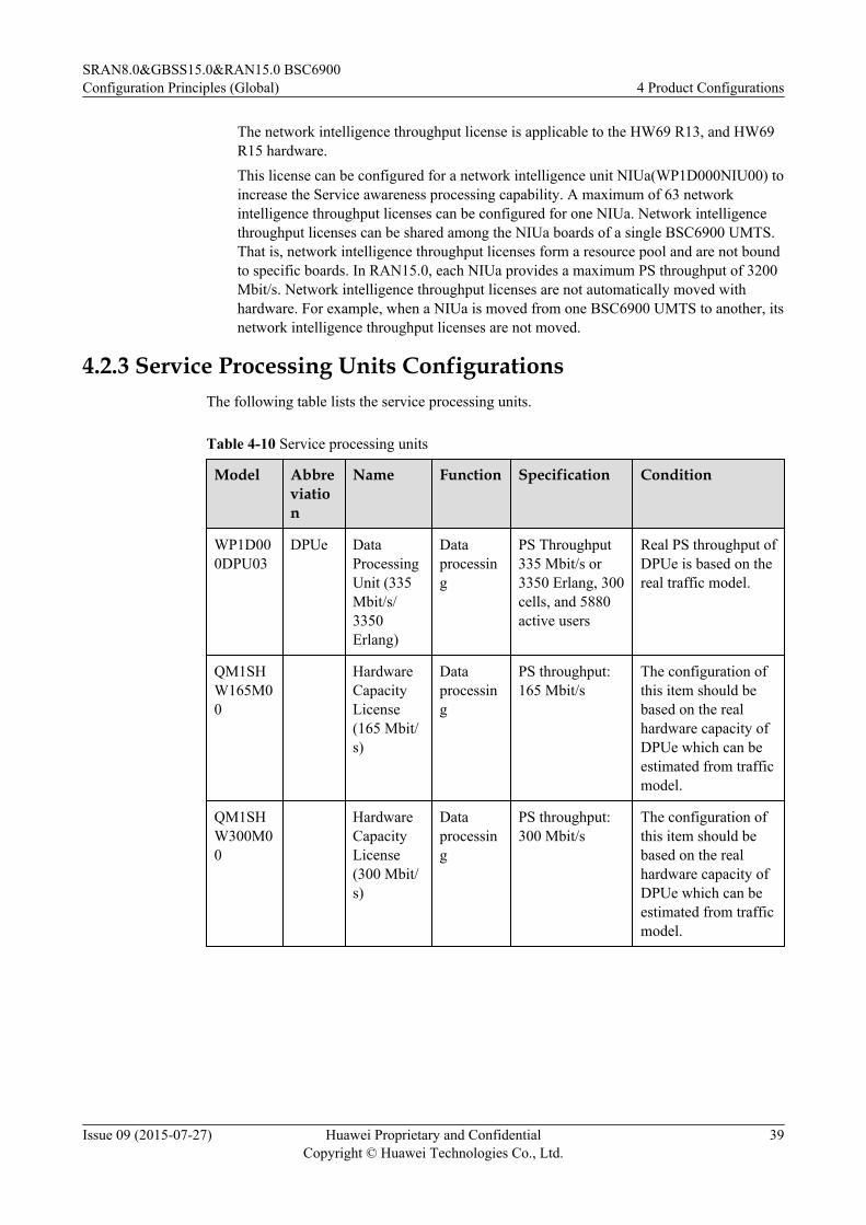
The network intelligence throughput license is applicable to the HW69 R13, and HW69R15 hardware.This license can be configured for a network intelligence unit NIUa(WP1D000NIU00) toincrease the Service awareness processing capability. A maximum of 63 networkintelligence throughput licenses can be configured for one NIUa. Network intelligencethroughput licenses can be shared among the NIUa boards of a single BSC6900 UMTS.That is, network intelligence throughput licenses form a resource pool and are not boundto specific boards. In RAN15.0, each NIUa provides a maximum PS throughput of 3200Mbit/s. Network intelligence throughput licenses are not automatically moved withhardware. For example, when a NIUa is moved from one BSC6900 UMTS to another, itsnetwork intelligence throughput licenses are not moved.
4.2.3 Service Processing Units ConfigurationsThe following table lists the service processing units.
Table 4-10 Service processing units
Model Abbreviation
Name Function Specification Condition
WP1D000DPU03
DPUe DataProcessingUnit (335Mbit/s/3350Erlang)
Dataprocessing
PS Throughput335 Mbit/s or3350 Erlang, 300cells, and 5880active users
Real PS throughput ofDPUe is based on thereal traffic model.
QM1SHW165M00
HardwareCapacityLicense(165 Mbit/s)
Dataprocessing
PS throughput:165 Mbit/s
The configuration ofthis item should bebased on the realhardware capacity ofDPUe which can beestimated from trafficmodel.
QM1SHW300M00
HardwareCapacityLicense(300 Mbit/s)
Dataprocessing
PS throughput:300 Mbit/s
The configuration ofthis item should bebased on the realhardware capacity ofDPUe which can beestimated from trafficmodel.
SRAN8.0&GBSS15.0&RAN15.0 BSC6900Configuration Principles (Global) 4 Product Configurations
Issue 09 (2015-07-27) Huawei Proprietary and ConfidentialCopyright © Huawei Technologies Co., Ltd.
39
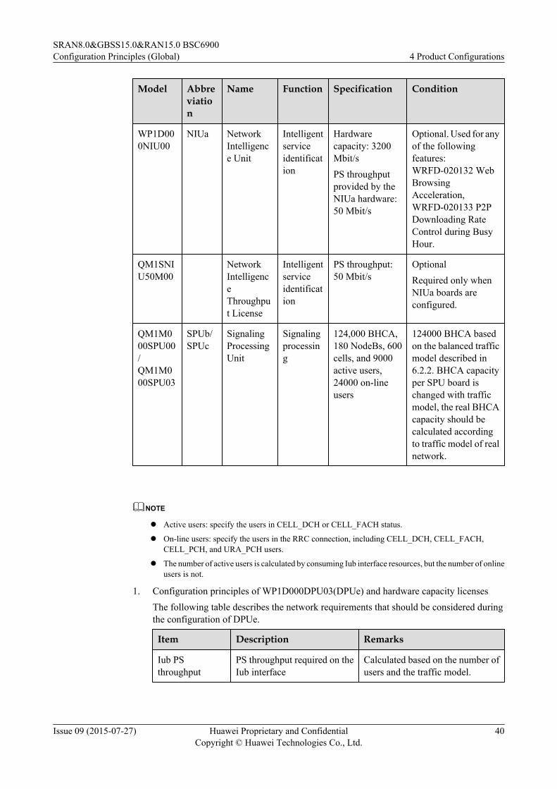
Model Abbreviation
Name Function Specification Condition
WP1D000NIU00
NIUa NetworkIntelligence Unit
Intelligentserviceidentification
Hardwarecapacity: 3200Mbit/sPS throughputprovided by theNIUa hardware:50 Mbit/s
Optional. Used for anyof the followingfeatures:WRFD-020132 WebBrowsingAcceleration,WRFD-020133 P2PDownloading RateControl during BusyHour.
QM1SNIU50M00
NetworkIntelligenceThroughput License
Intelligentserviceidentification
PS throughput:50 Mbit/s
OptionalRequired only whenNIUa boards areconfigured.
QM1M000SPU00/QM1M000SPU03
SPUb/SPUc
SignalingProcessingUnit
Signalingprocessing
124,000 BHCA,180 NodeBs, 600cells, and 9000active users,24000 on-lineusers
124000 BHCA basedon the balanced trafficmodel described in6.2.2. BHCA capacityper SPU board ischanged with trafficmodel, the real BHCAcapacity should becalculated accordingto traffic model of realnetwork.
NOTE
l Active users: specify the users in CELL_DCH or CELL_FACH status.
l On-line users: specify the users in the RRC connection, including CELL_DCH, CELL_FACH,CELL_PCH, and URA_PCH users.
l The number of active users is calculated by consuming Iub interface resources, but the number of onlineusers is not.
1. Configuration principles of WP1D000DPU03(DPUe) and hardware capacity licensesThe following table describes the network requirements that should be considered duringthe configuration of DPUe.
Item Description Remarks
Iub PSthroughput
PS throughput required on theIub interface
Calculated based on the number ofusers and the traffic model.
SRAN8.0&GBSS15.0&RAN15.0 BSC6900Configuration Principles (Global) 4 Product Configurations
Issue 09 (2015-07-27) Huawei Proprietary and ConfidentialCopyright © Huawei Technologies Co., Ltd.
40

Item Description Remarks
Iub CS traffic CS Erlang required on the Iubinterface
Calculated based on the number ofusers and the traffic model.
Active users Number of concurrent activeusers required by theBSC6900 UMTS user plane
Calculated based on the number ofusers and the traffic model.
Cell number Number of cells that need to bemanaged by the BSC6900UMTS
Determined based on the networkplan
a. In a newly deployed network:Assume that the user plane capacity requirements on the Iub interface of a networkare aMbit/s (PS throughput),bErlang (Iub CS traffic volume),c(number of cells),andn (number of active users).The real PS throughput capacity of DPUe can be estimated from the PS RAB meandata rate in active state:If PS RAB Mean data rate in active state (UL+DL)(kbps) ranges (0, 16], PSThroughput Capacity per DPUe(Mbps) = PS RAB Mean data rate * 5.625;If PS RAB Mean data rate in active state (UL+DL)(kbps) ranges (16, 40], PSThroughput Capacity per DPUe(Mbps) = 90+(PS RAB Mean data rate – 16)* 6.67;If PS RAB Mean data rate in active state (UL+DL)(kbps) ranges (40, 64], PSThroughput Capacity per DPUe(Mbps) = 250 + (PS RAB Mean data rate – 40) * 2.08;If PS RAB Mean data rate in active state (UL+DL)(kbps) ranges (64, 128], PSThroughput Capacity per DPUe(Mbps) = 300 + (PS RAB Mean data rate – 64) * 2.03;If PS RAB Mean data rate in active state (UL+DL)(kbps) ranges (128, 196], PSThroughput Capacity per DPUe(Mbps) = 430 + (PS RAB Mean data rate – 128) *1.47;If PS RAB Mean data rate in active state (UL+DL)(kbps) ranges (196, 448], PSThroughput Capacity per DPUe(Mbps) = 530 + (PS RAB Mean data rate – 128) *1.07;
If PS RAB Mean data rate in active state (UL+DL)(kbps) ranges (448, ∞], PSThroughput Capacity per DPUe(Mbps) = 800.Then, the number of DPUe boards required in the network, represented by N_DPUe,can be calculated with the following formula: N_DPUe = ROUNDUP(MAX(a/PSThroughput Capacity per DPUe + b/3350, c/300, n/5880, 2))
NOTE
A minimum of two DPUe boards can be configured. A maximum of 50 DPUe boards can beconfigured.
N_DPUe_PS = ROUNDUP(a/PS Throughput Capacity per DPUe)If
N_DPUe_PS x 335 ≥ a, no hardware capacity license needs to be configured.Otherwise,
SRAN8.0&GBSS15.0&RAN15.0 BSC6900Configuration Principles (Global) 4 Product Configurations
Issue 09 (2015-07-27) Huawei Proprietary and ConfidentialCopyright © Huawei Technologies Co., Ltd.
41

Number of required hardware capacity licenses (165 Mbit/s) (represented by N_165)= Min{N_DPUe, ROUNDUP[(a –N_DPUe_PS x 335)/165]}
If N_165 x 165 + N_DPUe_PS x 335 ≥ a, no hardware capacity license (300 Mbit/s) needs to be configured. Otherwise,
Number of required hardware capacity licenses (300 Mbit/s) (represented by N_300)= Min{N_165, ROUNDUP[(a – N_DPUe_PS x 335 – N_165 x 165)/300]}
b. In capacity expansion scenarios:
Calculate the number of required DPUe boards, hardware capacity licenses (165 Mbit/s), and hardware capacity licenses (300 Mbit/s) by referring to the calculationprocedure provided previously for a newly deployed network.
Number of DPUe boards = Number of DPUe boards after capacity expansion –Number of DPUe boards before capacity expansion
Number of hardware capacity licenses (165 Mbit/s) = Number of hardware capacitylicenses (165 Mbit/s) after capacity expansion – Number of hardware capacity licenses(165 Mbit/s) before capacity expansion
Number of hardware capacity licenses (300 Mbit/s) = Number of hardware capacitylicenses (300 Mbit/s) after capacity expansion – Number of hardware capacity licenses(300 Mbit/s) before capacity expansion
2. Configuration principles of WP1D000NIU00(NIUa) and QM1SNIU50M00(Networkintelligence throughput license):
If the Service awareness function needs to be provided, an NIUa must be configured.
Iub PS throughput: a Mbit/s
Number of required NIUa boards (represented by N_NIUa) = ROUNDUP(a/3200, 0)
One NIUa provides 50 Mbit/s PS throughput. If the value if a is larger than 50, then
N_QM1SNIU50M00 = ROUNDUP((a – N_NIUa x 50)/50, 0).
Otherwise,
N_QM1SNIU50M00 = 0.
3. Configuration principles of QM1M000SPU00 (SPUb)/QM1M000SPU03 (SPUc)
The following table describes the network requirements that should be considered duringthe configuration of QM1M000SPU00 (SPUb)/QM1M000SPU03 (SPUc).
Item Description Remarks
BHCA requirement BHCA that need to besupported in the network
Calculated based on thenumber of users and the trafficmodel.
Active users Number of concurrent activeusers that need to be supportedthe BSC6900 UMTS controlplane
Calculated based on thenumber of users and the trafficmodel.
On-line users Number of concurrent on-lineusers that need to be supportedthe BSC6900 UMTS controlplane
Calculated based on thenumber of users and the trafficmodel.
SRAN8.0&GBSS15.0&RAN15.0 BSC6900Configuration Principles (Global) 4 Product Configurations
Issue 09 (2015-07-27) Huawei Proprietary and ConfidentialCopyright © Huawei Technologies Co., Ltd.
42

Item Description Remarks
NodeB number Number of NodeBs that needto be managed by theBSC6900 UMTS
Determined based on thenetwork plan
Cell number Number of cells that need to bemanaged by the BSC6900UMTS
Determined based on thenetwork plan
a. In a newly deployed network:
Number of SPUb(SPUc) boards = ROUNDUP(MAX(BHCA required by the targetnetwork/BHCA supported by one SPUb(SPUc), Number of active users /Number ofactive users supported by one SPUb(SPUc), Number of on-line users /Number of on-line users supported by one SPUb(SPUc), Number of NodeBs required by the targetnetwork/Number of NodeBs supported by one SPUb(SPUc), Number of cells in thetarget network/Number of cells supported by one SPUb(SPUc)))
The BHCA supported by one SPUb(SPUc) depend on the traffic model. If the actualtraffic model of a network differs greatly from the balanced UMTS traffic modeldescribed in section 6.2.2 UMTS Traffic Model. BHCA supported by one SPUb(SPUc) need to be recalculated based on the actual traffic model.
b. In capacity expansion scenarios:
Number of SPUb(SPUc) boards = Number of SPUb(SPUc) boards after capacityexpansion – Number of SPUb(SPUc) boards before capacity expansion
4.2.4 Interface Boards ConfigurationsThe BSC6900 UMTS provides various interfaces to meet the requirements of different networkstructures.
1. Specification of Interface boards
Table 4-11 lists the interface boards required by the BSC6900 UMTS that adopts the HW69R16 hardware.
Table 4-11 Interface boards required by the BSC6900 UMTS that adopts the HW69 R16hardware
Model Abbreviation
Name Where toApply
SessionSetup/ReleaseTimes
CID/UDP(Activeusers)
WP1D000AEU00 AEUa ATM InterfaceUnit (32 E1)
Iub 500 23,000
WP1D000PEU00 PEUc IP Interface Unit(32 E1)
Iub 500 23,000
SRAN8.0&GBSS15.0&RAN15.0 BSC6900Configuration Principles (Global) 4 Product Configurations
Issue 09 (2015-07-27) Huawei Proprietary and ConfidentialCopyright © Huawei Technologies Co., Ltd.
43

Model Abbreviation
Name Where toApply
SessionSetup/ReleaseTimes
CID/UDP(Activeusers)
WP1D000AOU01 AOUc ATM InterfaceUnit (4 STM-1,Channelized)
Iub 5000 79,000
WP1D000POU01 POUc IP Interface Unit(4 STM-1,Channelized)
Iub 5000 129,000
WP1D000UOI01 UOIc ATM InterfaceUnit (8 STM-1,Unchannelized)
Iub/Iu/Iur
5000 79,000
WP1D000GOU01/WP1D000GOU03
GOUc/GOUe
IP Interface Unit(4 GE, Optical)
Iub/Iu/Iur-pnote
5000 129,000
WP1D000FG201 FG2c IP Interface Unit(12 FE/4 GE,Electrical)
Iub/Iu/Iur-pnote
5000 129,000
NOTE
The Iur-p is a private interface connecting RNCs to facilitate the RNC in Pool feature.
Table 4-12 Specifications of interface boards on the Iub/Iur interface
Model Iub/Iur NodeB
Voice(Erlang)
VP(Erlang)
UL(Mbit/s)
DL(Mbit/s)
UL+DL(Mbit/s)
WP1D000AEU00 2800 680 45 45 90 32
WP1D000PEU00 2800 850 60 60 120 32
WP1D000AOU01 18,000
5500 300 300 600 500
WP1D000POU01 18,000
6000 400 400 800 252
WP1D000UOI01 18,000
9000 800 800 1200 500
SRAN8.0&GBSS15.0&RAN15.0 BSC6900Configuration Principles (Global) 4 Product Configurations
Issue 09 (2015-07-27) Huawei Proprietary and ConfidentialCopyright © Huawei Technologies Co., Ltd.
44

WP1D000GOU01/WP1D000GOU03/WP1D000FG201
18,000
9,000 2600 2600 2600 500
Table 4-13 Specifications of interface boards on the Iu-CS/Iu-PS interface
Model Iu-CS Iu-PS
Voice(Erlang)
VP(Erlang)
UL(Mbit/s)
DL(Mbit/s)
UL+DL(Mbit/s)
IU PS On-line Users(TEID)
WP1D000UOI01 18,000 9000 900 900 1800 200,000
WP1D000GOU01/WP1D000GOU03/WP1D000FG201
18,000 9000 3200 3200 3200 200,000
NOTE
l The specifications UL (Mbit/s), DL (Mbit/s), and UL+DL (Mbit/s) listed in Table 3-4 and Table3-5 are based on the traffic type DL/UL64/384 kbit/s.
l One active CS user consumes two CIDs/UDPs, and one active HSPA PS user consumes threeCIDs/UDPs.
l One active CS user consumes one Iu-CS CID/UDP, and one active PS user consumes one Iu-PSTEID(Tunnel Endpoint ID).
l The number of session setups/releases indicates the signaling processing capability of interfaceboards and is applicable to the Iub and Iu interfaces. The following table lists the mappingbetween the interface signaling processing requirements and the traffic model.
Table 4-14 Session setup/release times in Iub/Iu for every signaling procedure in trafficmodel
Control Plane TrafficParameter
Unit Iub sessionsetup / releasetimes
Iu-PS sessionsetup/releasetimes
CS voice call persubscriber per BH
times 2 -
Handover times per CSvoice call (Inter/IntraRNC soft handover)
times/call 2 -
PS call per subscriber perBH
times 3 1
SRAN8.0&GBSS15.0&RAN15.0 BSC6900Configuration Principles (Global) 4 Product Configurations
Issue 09 (2015-07-27) Huawei Proprietary and ConfidentialCopyright © Huawei Technologies Co., Ltd.
45

Control Plane TrafficParameter
Unit Iub sessionsetup / releasetimes
Iu-PS sessionsetup/releasetimes
Handover times per PScall (Inter/Intra RNC softhandover)
times/call 2 -
PS channel switch per PScall
times/call 1 0.5
Cell update per PS call times/call - 0.5
NAS signaling persubscriber per BH (times)
times/persubscriber
1 -
NOTE
The specifications of interface boards on the Iur interface are the same as those of interface boardson the Iub interface.
The processing capability specifications of each interface board are the maximum specificationswhen the interface board processes only the corresponding type of service. The configuredspecifications are listed in the "NodeB" column.
2. Configuration rules of interface boards
The following table describes the network requirements that should be considered during theconfiguration of interface boards.
Interface Item Description Remarks
Iub Iub transmissiontype
Transmission type used onthe Iub interface of thenetwork
Determined based onthe network plan
Iub PS throughput PS throughput that needs tobe supported on the Iubinterface
Calculated based on thenumber of users and thetraffic model.
Iub CS traffic CS Erlang that needs to besupported on the Iubinterface
Iub session setupand releaserequirement in BH
Session setup and releasecapacity that matches thenetwork BHCA capacity
Iub active users(CID/UDP)
Number of concurrent activeusers (CID/UDP)that needto be supported theBSC6900 UMTS user plane.
SRAN8.0&GBSS15.0&RAN15.0 BSC6900Configuration Principles (Global) 4 Product Configurations
Issue 09 (2015-07-27) Huawei Proprietary and ConfidentialCopyright © Huawei Technologies Co., Ltd.
46

Interface Item Description Remarks
NodeB number Number of NodeBs thatneed to be managed by theBSC6900 UMTS
Determined based onthe network plan
Iu-CS Iu-CS transmissiontype
Transmission type used onthe Iu-CS interface of thenetwork
Determined based onthe network plan
Iu-CS CS traffic CS traffic volume on the Iu-CS interface
Calculated based on thenumber of users and thetraffic model.
Iu-CS active users Number of concurrent activeusers that need to besupported the Iu-CSinterface of the BSC6900UMTS
Iu-CS session setupand releaserequirement in BH
Number of sessions thatneed to be supported on theIu-CS interface of theBSC6900 UMTS
Iu-PS Iu-PS transmissiontype
Transmission type used onthe Iu-PS interface of thenetwork
Determined based onthe network plan
Iu-PS throughput PS throughput that needs tobe supported on the Iu-PSinterface
Calculated based on thenumber of users and thetraffic model.
Iu-PS on-line users Number of concurrent on-line users that need to besupported the Iu-PSinterface of the BSC6900UMTS
Iu-PS session setupand releaserequirement in BH
Number of sessions thatneed to be supported on theIu-PS interface of theBSC6900 UMTS
The configuration principles of interface boards are as follows:
1. The number of interface boards required on the Iub interface can be calculated in thefollowing way:
The Iub interface can use any of the following transmission modes:
Case 1: hybrid Iub - E1 (ATM) && Iub-Ethernet (IP);
Case 2: hybrid Iub - E1 (IP) && Iub-Ethernet (IP);
Case 3: hybrid Iub - VC12-STM-1 (ATM) && Iub-Ethernet (IP);
SRAN8.0&GBSS15.0&RAN15.0 BSC6900Configuration Principles (Global) 4 Product Configurations
Issue 09 (2015-07-27) Huawei Proprietary and ConfidentialCopyright © Huawei Technologies Co., Ltd.
47

Case 4: hybrid Iub - VC4-STM-1 (ATM) && Iub-Ethernet (IP);Case 5: hybrid Iub - VC12-STM-1 (IP) && Iub-Ethernet (IP);Case 6: E1 (ATM);Case 7: VC12 - STM-1 (ATM);Case 8: VC4 - STM-1 (ATM);Case 9: E1 (IP);Case 10: Ethernet (IP);Case 11: VC12 - STM-1 (IP)The number of required Iub interface boards can be calculated on the basis of any of thefollowing aspects: service processing capability (Erlang and payload throughput), portbandwidth, number of NodeBs, signaling processing capability, and number of concurrentactive users. The required number of Iub interface boards is the maximum among thesevalues calculated from the preceding aspects.Number of Iub interface boards = MAX(Number of Iub interface board_Traffic, Numberof Iub interface board_Bandwidth, Number of Iub interface board_NodeB, Number of IubInterface Board_Session setup/release, Number of Iub Interface Board_CIDUDP)where,Number of Iub interface board_Traffic = Iub Voice Traffic/Iub Voice specification + IubCS Data Traffic/Iub CS data specification + MAX((Iub PS DL Throughput + MBMStraffic)/Iub PS DL specification, Iub PS UL Throughput/Iub PS UL specification, (Iub PSDL Throughput + MBMS traffic+ Iub PS UL Throughput)/Iub PS DL+UL specification)Number of Iub interface board_Bandwidth = (Iub OAM Transmission bandwidthrequirement + MAX(Iub DL Transmission Bandwidth (data) +Iub DL TransmissionBandwidth (signaling) +Iub DL MBMS Transmission Bandwidth, Iub UL TransmissionBandwidth (data) + Iub UL Transmission Bandwidth (signaling)))/TransmissionBandwidth per Interface port/Number of ports per interface boardNumber of Iub interface board_NodeB = NodeB number/NodeB Capacity per InterfaceBoardNumber of Iub Interface Board_Session setup/release= Iub session setup and release requirement in BH/capacity of session setup and sessionrelease per second of interface board/3600Number of Iub Interface Board_CIDUDP= Iub active users (CID/UDP)/CIDUDP supported by per interface boardIn the preceding formulas, Iub Voice specification, Iub CS data specification, Iub PS DLspecification, Iub PS UL specification, Iub PS DL + UL specification, Number of ports perinterface board, NodeB capacity per interface board, capacity of session setup and sessionrelease per second of interface board, and active users supported by per interface board arespecifications of interface boards(CID/UDP). The other items are the results of BSC6900dimensioning.
2. The Iur, Iu-CS, and Iu-PS interfaces can use any of the following transmission modes:Case 1: VC4-STM-1 (ATM);Case 2: GE Electrical (IP);Case 3: GE Optical (IP);The numbers of required Iur, Iu-CS, and Iu-PS interface boards can be calculated on thebasis of any of the following four aspects: service processing capability (Erlang and payload
SRAN8.0&GBSS15.0&RAN15.0 BSC6900Configuration Principles (Global) 4 Product Configurations
Issue 09 (2015-07-27) Huawei Proprietary and ConfidentialCopyright © Huawei Technologies Co., Ltd.
48

throughput), port bandwidth, signaling processing capability, and number of concurrentactive users. The required numbers of Iur, IU-CS, and Iu-PS interface boards are themaximum among the four values calculated from the preceding four aspects.For the Iu-CS interface,Number of Iu-CS interface board_Traffic= Iu-CS CS Voice Traffic/Iu-CS Voice specification + Iu-CS CS Data Traffic/Iu-CS dataspecificationNumber of Iu-CS interface board_Bandwidth= MAX((Iu-CS DL Transmission Bandwidth (data) + Iu-CS DL Transmission Bandwidth(signaling)), (Iu-CS UL Transmission Bandwidth (data) + Iu-CS UL TransmissionBandwidth (signaling)))/Transmission Bandwidth per Interface port/Number of ports perinterface boardNumber of Iu-CS Interface Board_Session setup/release= Iu-CS session setup and release requirement in BH/Capacity of session setup and sessionrelease per second of interface board/3600Number of Iu-CS Interface Board_CIDUDP= Iu-CS active users/CIDUDP supported by per interface boardNumber of Iu-CS interface board= MAX(Number of Iu-CS interface board_Traffic, Number of Iu-CS interfaceboard_Bandwidth, Number of Iu-CS Interface Board_Session setup/release, Number of Iu-CS Interface Board_CIDUDP)For the Iu-PS interface,Number of Iu-PS interface board_Traffic= MAX[Iu-PS DL Throughput/Iu PS DL specification, Iu-PS UL Throughput/Iu PS ULspecification, (Iu-PS DL Throughput + Iu-PS UL Throughput)/Iu PS DL+UL specification]Number of Iu-PS interface board_bandwidth= MAX[Iu-PS DL Transmission Bandwidth (data) + Iu-PS DL Transmission Bandwidth(signaling), Iu-PS UL Transmission Bandwidth (data) + Iu-PS UL Transmission Bandwidth(signaling)]/Transmission Bandwidth per Interface port/Number of ports per interfaceboardNumber of Iu-PS Interface Board_Session setup/release= Iu-PS session setup and release requirement in BH/Capacity of session setup and sessionrelease per second of interface board/3600Number of Iu-PS Interface Board_on-line users= Iu-PS on-line users/on-line users supported by per interface boardNumber of Iu-PS interface board= MAX(Number of Iu-PS interface board_Traffic, Number of Iu-PS interfaceboard_bandwidth, Number of Iu-PS Interface Board_Session setup/release, Number of Iu-PS Interface Board_on-line users)For the Iur interface,Number of Iur interface boards_Traffic= Iur Voice Traffic/Iub CS Voice_specification + Iur CS Data Traffic/Iub CSdata_specification + MAX(Iur PS DL Throughput/Iub PS DL_specification, Iur PS ULThroughput/Iub PS UL_specification)
SRAN8.0&GBSS15.0&RAN15.0 BSC6900Configuration Principles (Global) 4 Product Configurations
Issue 09 (2015-07-27) Huawei Proprietary and ConfidentialCopyright © Huawei Technologies Co., Ltd.
49

Number of Iur interface board_bandwidth= MAX[Iur DL Transmission Bandwidth (data) + Iur DL Transmission Bandwidth(signaling), Iur UL Transmission Bandwidth (data) + Iur UL Transmission Bandwidth(signaling)]/Transmission Bandwidth per Interface port/Number of ports per interfaceboardNumber of Iur Interface Board_Session setup/release= Iur session setup and release requirement in BH/Capacity of session setup and sessionrelease per second of interface board/3600Number of Iur Interface Board_CIDUDP= Total Iur active users(CID/UDP)/CIDUDP supported by per interface boardNumber of Iur interface boards= MAX(Number of Iur interface board_Traffic, Number of Iur interface board_bandwidth,Number of Iur Interface Board_Session setup/release, Number of Iur InterfaceBoard_CIDUDP)If there are several IUR interfaces, and it is not allowed that these IUR interfaces shareports of interface board with each other, then:Number of Iur Interface Board_port number=Iur interface number/ port number per interface boardNumber of Iur interface board= MAX(Number of Iur interface board_Traffic, Number of Iur interface board_bandwidth,Number of Iur Interface Board_Session set-up/release, Number of Iur InterfaceBoard_CIDUDP, Number of Iur Interface Board_port number)In the preceding formulas, the following items are the specifications for the interfaceboards: Iu-CS voice specification, Iu-CS data specification, Iu-PS DL specification, Iu-PSUL specification, Iu-PS DL + UL specification, Number of ports per interface board,Transmission bandwidth per interface port, Number of session setups and releases persecond of interface board, and active users supported by per interface board. The otheritems are the results of BSC6900 dimensioning.
3. RNC interface boards supports the two backup modes:
a. In 1+1 backup mode, the actual number of interface boards required is twice thenumber calculated according to the network capacity requirements.The number of interface boards is the sum of interface boards required on the Iub, Iu-CS, Iu-PS, and Iur interfaces, SUM(N_IUB_INT, N_Iu-CS_INT, N_Iu-PS_INT,N_Iur)*2
b. The BSC6900 UMTS supports the N+1 backup mode on only the FG2c and GOUc/GOUe boards with resource pools enabled.If Iu-CS Iu-PS Iur share the interface board, the number of interface boards should becalculated from: ROUNDUP(N_IUB_INT, 0)+1, ROUNDUP[SUM(Iu-CS, Iu-PS,Iur, 0)] +1.
SRAN8.0&GBSS15.0&RAN15.0 BSC6900Configuration Principles (Global) 4 Product Configurations
Issue 09 (2015-07-27) Huawei Proprietary and ConfidentialCopyright © Huawei Technologies Co., Ltd.
50

4.2.5 Clock Boards Configurations
Table 4-15 Clock boards
Model Abbreviation
Name Function
WP1D000GCU01/WP1D000GCU02
GCUa/GCUb General Clock Unit Provides general clocksignals
QW1D000GCG01/QW1D000GCG02
GCGa/GCGb GPS&Clock ProcessingUnit
Provides GPS clocksignals
The GCUa(GCUb) is optional. When a BSC6900 UMTS does not use GPS clock signals, a pairof general clock units can be configured for the BSC6900 UMTS.
The GCGa(GCGb) is optional. When a BSC6900 UMTS needs to use GPS clock signals, a pairof GPS&clock processing units can be configured for the BSC6900 UMTS.
4.2.6 Principles for Board ConfigurationsBoards must be configured in slots according to the following principles:
1. An OMUc board must be configured in slots 24 and 25 of the MPS.
2. Clock boards (GCU/GCG) must be configured in slots 12 and 13 of the MPS.
3. The SCUb boards must be configured in slots 6 and 7 of the MPS and EPS.
4. Service processing units (DPUe/SPUb/SPUc/NIUa) can be configured in any slots exceptthe slots for the OMUc, clock boards, and SCUb boards. It is recommended that serviceprocessing units be configured in small-numbered slots (starting from slot 0) and large-numbered slots be reserved for interface boards.
5. Interface boards can be configured only in slots 14 to 27 (except slots 24 and 25 in theMPS).
6. Service processing units and interface boards must be distributed evenly among subracksto reduce the CPU and swapping resources consumed during inter-subrack switching andavoid the inter-subrack bandwidth limiting the traffic volume. Assume that there are 9DPUe boards, 12 SPUb(SPUc) boards, 6 interface boards, and 3 subracks. Then, it isrecommended that 3 DPUe boards, 4 SPUb(SPUc) boards, and 2 interface boards beconfigured in each subrack.
7. The SPU boards must be configured in active/standby mode. The DPU and NIU boardsmust be configured in load sharing mode by using a resource pool. The OMU, SCU, andGCU/GCG boards must be configured in active/standby mode. Two slots must be reservedfor the SAU boards (one or two SAU can be configured).
8. The MPS supports a maximum of 9 pairs of SPU boards and 9 DPUe boards.
9. The EPS supports a maximum of 9 pairs of SPU boards and 9 DPUe boards.
10. It is recommended that the SAU be configured in the MPS with two slots reserved.
11. It is recommended that the Iur-P interface board used for the RNC In Pool feature beconfigured in the MPS.
SRAN8.0&GBSS15.0&RAN15.0 BSC6900Configuration Principles (Global) 4 Product Configurations
Issue 09 (2015-07-27) Huawei Proprietary and ConfidentialCopyright © Huawei Technologies Co., Ltd.
51

For the actual configuration operation, see Examples of Typical Configurations in section 4.4.2BSC6900 UMTS Examples of Typical Configurations.
4.2.7 Subracks ConfigurationsThe following table lists the configuration of the subracks.
Table 4-16 Configuration of the Subracks
Model Abbreviation
Name
QM1P00UMPS01 MPS Main Processing Subrack
QM1P00UEPS01 EPS Extended Processing Subrack
WP1X000OMU02 OMUc Operation and Maintenance Unit
WP1D000SAU01 SAUc Service Aware Unit
WP1D000SCU01 SCUb GE Switching network and Control Unit
Configuration principles of the MPS:
One MPS must be configured in a BSC6900 UMTS.
Configuration principles of the EPS:
A maximum of five EPSs can be configured in a BSC6900 UMTS.
1. In a newly deployed network:Number of EPSs_1 = ROUNDUP[(Number of required SPU boards – Number of SPUboards that can be housed by MPS)/9]If Number of required SPU boards < Number of SPU boards that can be housed by MPS,then Number of EPSs_1 = 0.Number of SPU boards that can be housed by MPS = 9Number of SPU boards can be housed in the MPS: 9 pairsNumber of SPU boards can be housed in the EPS: 9 pairsNumber of EPSs_2 = ROUNDUP[(Number of required DPUe boards – Number of DPUeboards that can be housed by MPS)/9]If Number of required DPUe boards < Number of DPUe boards that can be housed by MPS,then Number of EPSs_2 = 0.Number of DPUe boards that can be housed by MPS = 9Number of DPUe boards can be housed in the EPS: 9Number of EPSs_3 = ROUNDUP[((Number of slots required by interface boards – Numberof slots for interface boards in MPS)/14), 0]If Number of slots required by interface boards < Number of slots for interface boards inMPS, then Number of EPSs_3 = 0.Number of slots for interface boards in MPS = 12
SRAN8.0&GBSS15.0&RAN15.0 BSC6900Configuration Principles (Global) 4 Product Configurations
Issue 09 (2015-07-27) Huawei Proprietary and ConfidentialCopyright © Huawei Technologies Co., Ltd.
52

Number of EPSs_4 = ROUNDUP[(Number of required SPUb boards x 2Note + Number ofrequired DPUe boards + Number of slots required by interface boards + Number of requiredNIUa boards – Number of slots in MPS)/26]
If Number of required SPU boards x 2 + Number of required DPUe boards + Number ofslots required by interface boards + Number of required NIUa boards < Number of slots inMPS, then Number of EPSs_4 = 0.
Number of slots in MPS = 20 (Two slots have been reserved for the SAUc.)
Number of EPSs = MAX(Number of EPSs_1, Number of EPSs_2, Number of EPSs_3,Number of EPSs_4)
NOTE
The number of slots occupied by each pair of SPUb is 2.
The default number of SAU board is one for EBC. If the customer has purchased and usedHuawei Nastar or other OSS feature such as SON, one or two SAUc boards need to beconfigured in the MPS of the BSC6900. The number of SAUc boards is up to OSS.
Configuration Scenarios Number of SAUboards (pcs)
Nastar Only 1
At least one in EBC and SON 1
Nastar, and at least one in EBC and SON 2
2. In capacity expansion scenarios:
Number of EPSs = Number of EPSs after capacity expansion – Number of EPSs beforecapacity expansion
4.2.8 Cabinets ConfigurationsThe following table lists the configuration of the cabinets.
Table 4-17 Cabinets
Model Name Function
WP1B4PBCBN00 BSC6900 cabinet Cabinet
Configuration principles of cabinets:
A maximum of two cabinets can be configured for a BSC6900 UMTS. Each cabinet canaccommodate three subracks.
1. In a newly deployed network:
Number of cabinets = ROUNDUP((Number of MPSs + Number of EPSs)/3, 0)
Here, Number of MPSs = 1.
2. In capacity expansion scenarios:
SRAN8.0&GBSS15.0&RAN15.0 BSC6900Configuration Principles (Global) 4 Product Configurations
Issue 09 (2015-07-27) Huawei Proprietary and ConfidentialCopyright © Huawei Technologies Co., Ltd.
53

Number of cabinets = Number of cabinets after capacity expansion – Number of cabinetsbefore capacity expansion
4.2.9 Auxiliary MaterialsThe following table lists the auxiliary materials.
Table 4-18 Auxiliary materials
Model Name Function
QW1P8D442000 Trunk Cable 75-ohm trunk cable
QW1P8D442003 Trunk Cable 120-ohm trunk cable
QW1P0STMOM00 STM-1 Optical Connector STM-1 optical unit
QW1P00GEOM00 GE Optical Connector GE optical unit
QW1P0FIBER00 Optical Fiber Optical cable
QW1P0000IM00 Installation MaterialPackage
Installation material suite
QMAI00EDOC00 Documentation Electronic documentation
Configuration principles of the 75-ohm trunk cables (QW1P8D442000):
The 75-ohm trunk cables need to be in full configuration for a board.
Number of trunk cables = [Number of ATM interface units (32 E1s) + Number of IP interfaceunits (32 E1s)] x 2
NOTE
One trunk cable provides eight E1s. 32 E1s/8 E1s = 4. A trunk cable is a Y-shaped cable, which is connectedto both the active and standby boards.
Configuration principles of the 120-ohm trunk cables (QW1P8D442003):
The 120-ohm trunk cables need to be in full configuration for a board.
Number of trunk cables = [Number of ATM interface units (32 E1s) + Number of IP interfaceunits (32 E1s)] x 2
NOTE
One trunk cable provides eight E1s. 32 E1s/8 E1s = 4. A trunk cable is a Y-shaped cable, which is connectedto both the active and standby boards.
l Configuration principle of the STM-1 optical units (QW1P0STMOM00):The STM-1 optical units need to be in full configuration for an optical interface board.Number of STM-1 optical units = (Number of WP1D000AOU01s + Number ofWP1D000POU01s) x 4 + Number of WP1D000UOI01s x 8
l Configuration principle of the GE optical unit (QW1P00GEOM00):The GE optical units need to be in full configuration for an optical interface board.
SRAN8.0&GBSS15.0&RAN15.0 BSC6900Configuration Principles (Global) 4 Product Configurations
Issue 09 (2015-07-27) Huawei Proprietary and ConfidentialCopyright © Huawei Technologies Co., Ltd.
54

Number of GE optical units = Number of WP1D000GOU01s x 4
l Configuration principle of the optical cables (QW1P0FIBER00):
The optical cables are configured based on the number of optical modules required in theBSC6900. Number of optical cables = (Number of STM optical modules + Number of GEoptical modules) x 2
l Configuration principle of the installation material suite (QW1P0000IM00):
One installation material suite (QW1P0000IM00) is configured for each BSC6900 cabinet(WP1B4PBCBN00).
l Configuration principle of the electronic documentation (QMAI00EDOC00):
A set of electronic documentation (QMAI00EDOC00) is delivered with each BSC6900.
4.2.10 Description of RestrictionsPrinciples on inter-subrack switching
Huawei BSC6900 V900R011 uses the SCUa boards. A pair of active and standby SCUa boardscan process data at 4 Gbit/s on the physical layer. The SCUa boards in various subracks areconnected in star networking mode. Huawei BSC6900 V900R013 uses the SCUb boards. A pairof active and standby SCUb boards can process data at 40 Gbit/s on the physical layer. TheSCUb boards in various subracks are connected in chain mode.
If either of the active and standby board becomes faulty, the processing capability is halved.
If the SCU boards are not evenly configured among the subracks or services are not evenlydeployed among the subracks, the volume of inter-subrack data flows may sharply increase.Once the volume exceeds the capacity, services are interrupted. Therefore, all types of boardsshould be evenly configured among subracks, services should be evenly deployed, and the user-plane capacity should be similar.
For example,
if there are 12 pairs of SPUc boards, 15 DPUe boards, 4 NIUa boards, 3 pairs of Iub GOUeboards, 2 pairs of Iu GOUe boards, and 6 subracks, based on the preceding configurationprinciples, each subrack should be configured with 2 pairs of SPUc boards, 2 or 3 DPUe boards,1 NIUa boards or no NIUa boards, 1 pair of Iub GOUe boards or no Iub GOUe boards, 1 pairof Iu GOUe boards or no Iu GOUe boards. The subrack with more DPUe boards should beconfigured with more GOUe and NIUa boards. SAUc boards are configured in reserved slots inMPS. The following table lists a recommended configuration.
Subrack
SPUc(pair)
DPUe(pcs)
NIUa(pcs) Iub GOUe(pair)
Iu GOUe(pair)
SAUc(pcs)
MPS 2 3 1 1 1 2
EPS1 2 3 1 1 1 0
EPS2 2 3 1 1 0 0
EPS3 2 2 1 0 0 0
EPS4 2 2 0 0 0 0
EPS5 2 2 0 0 0 0
SRAN8.0&GBSS15.0&RAN15.0 BSC6900Configuration Principles (Global) 4 Product Configurations
Issue 09 (2015-07-27) Huawei Proprietary and ConfidentialCopyright © Huawei Technologies Co., Ltd.
55

Subrack
SPUc(pair)
DPUe(pcs)
NIUa(pcs) Iub GOUe(pair)
Iu GOUe(pair)
SAUc(pcs)
Total 12 15 4 3 2 2
4.3 BSC6900 GU Product ConfigurationsThe following describes the hardware configuration principles of the BSC6900 GU.
1. GSM boards and UMTS boards should not be configured in the same subrack.
2. One to four GSM subracks can be configured. One to five UMTS subracks can beconfigured.
3. The total number of GSM and UMTS subracks should be smaller than or equal to six.
4. Number of cabinets = ROUNDUP[(Number of GSM subracks + Number of UMTSsubracks)/3]. A maximum of two cabinets (excluding the cabinets housing TC subracks)can be configured.
5. When the BM/TC separated configuration mode is used, the MPS must work in GSM mode.
6. The NIUa board providing the service awareness function can be shared between GSM andUMTS and be configured both on the GSM and UMTS side.
7. Zero, one or two SAU boards can be configured in the BSC6900 GU mode.
The preceding principles apply to BSC6900 GU deployment and capacity expansion.
The procedure for configuring a newly deployed BSC6900 GU is as follows:
Step 1 Obtain the GSM and UMTS network parameter values.
Step 2 Perform dimensioning to obtain the GSM and UMTS network requirements respectively.
Step 3 Calculate the UMTS configuration and GSM configuration based on the network requirements.
Step 4 If the capacity required by the GSM configuration and UMTS configuration does not exceedthe BSC6900 GU specifications (that is, the total number of GSM subracks and UMTS subrackdoes not exceed six), then configuration calculation is complete. If the total required capacityexceeds the maximum specifications of one BSC6900 GU or the number of slots required forthe interface boards exceeds the limitation, an extra BSC6900 GU needs to be added.
----End
4.4 Examples of Typical Configurations
4.4.1 BSC6900 GSM Examples of Typical ConfigurationsThe following figure illustrates the typical procedure for configuring a BSC6900 GSM.
SRAN8.0&GBSS15.0&RAN15.0 BSC6900Configuration Principles (Global) 4 Product Configurations
Issue 09 (2015-07-27) Huawei Proprietary and ConfidentialCopyright © Huawei Technologies Co., Ltd.
56

Step 1 Input requirements.
Operator provides the network requirement which should include the information provided inthe following figure.
An example is given here. The input information is listed in the following table.
Network Parameter Value
TRX QTY 1024
HR Ratio 50%
A Erl: Um Erl 80%
Gos in Um interface 0.02
Gos in A interface 0.001
GPRS Active Sub 100,000
Static PDCH per Cell 4
Dynamic PDCH per Cell 8
Built-in PCU yes
SRAN8.0&GBSS15.0&RAN15.0 BSC6900Configuration Principles (Global) 4 Product Configurations
Issue 09 (2015-07-27) Huawei Proprietary and ConfidentialCopyright © Huawei Technologies Co., Ltd.
57

Network Parameter Value
BM/TC model (Separated or Combined) Separated
Whether to support GPS in BSC No
Whether to support TC POOL (If TC POOL, Input the quantity ofneeded CIC)
No
Step 2 Dimension.
Dimensioning will be carried out from three dimensions, as shown in the following figure.
Item Name Specification
1 TRX support capability A1
2 Abis E1 quantity A2
3 A CIC quantity A3
4 IWF quantity A4
5 BHCA A5
6 Gb A6
Step 3 Obtain the network capacity requirement to calculate the hardware requirement.
Item Name Configuration Beforethe CapacityExpansion
1 Subracks (MPS, EPS) B1
2 Data Processing Units (DPUf) B2
SRAN8.0&GBSS15.0&RAN15.0 BSC6900Configuration Principles (Global) 4 Product Configurations
Issue 09 (2015-07-27) Huawei Proprietary and ConfidentialCopyright © Huawei Technologies Co., Ltd.
58

Item Name Configuration Beforethe CapacityExpansion
3 Data Processing Units (DPUc, DPUg) B3
4 Extended Processing Units (XPUb) B4
5 Interface boards B5
6 Cabinets B6
----End
4.4.2 BSC6900 UMTS Examples of Typical ConfigurationsThe procedure of typical configuration can be carried out as follow steps.
Step 1 Input requirements.
Operator provides the network requirement which should include the information as listed inTable 4-19.
Table 4-19 Network specifications
Network Parameter Value
Total subscribers 800,000
Total NodeBs 600
Total cells 3000
Voice Traffic per CS voice subscriber in BH(Erlang ) 0.02
CS voice call duration (sec) 75
Handover times per CS call 8
CS voice call per subscriber per BH 0.96
PS call per subscriber per BH 2
Proportion of SHO for CS call 0.3
Handover times per PS call 5
Mean holding time (MHT) in DCH/H/FACH state per PS call(sec) 52
Mean holding time (MHT) in PCH per PS call(sec) 0
PS channel switch times per PS call 3
Cell update times per PS call 3
Proportion of SHO for PS call 0.3
SRAN8.0&GBSS15.0&RAN15.0 BSC6900Configuration Principles (Global) 4 Product Configurations
Issue 09 (2015-07-27) Huawei Proprietary and ConfidentialCopyright © Huawei Technologies Co., Ltd.
59
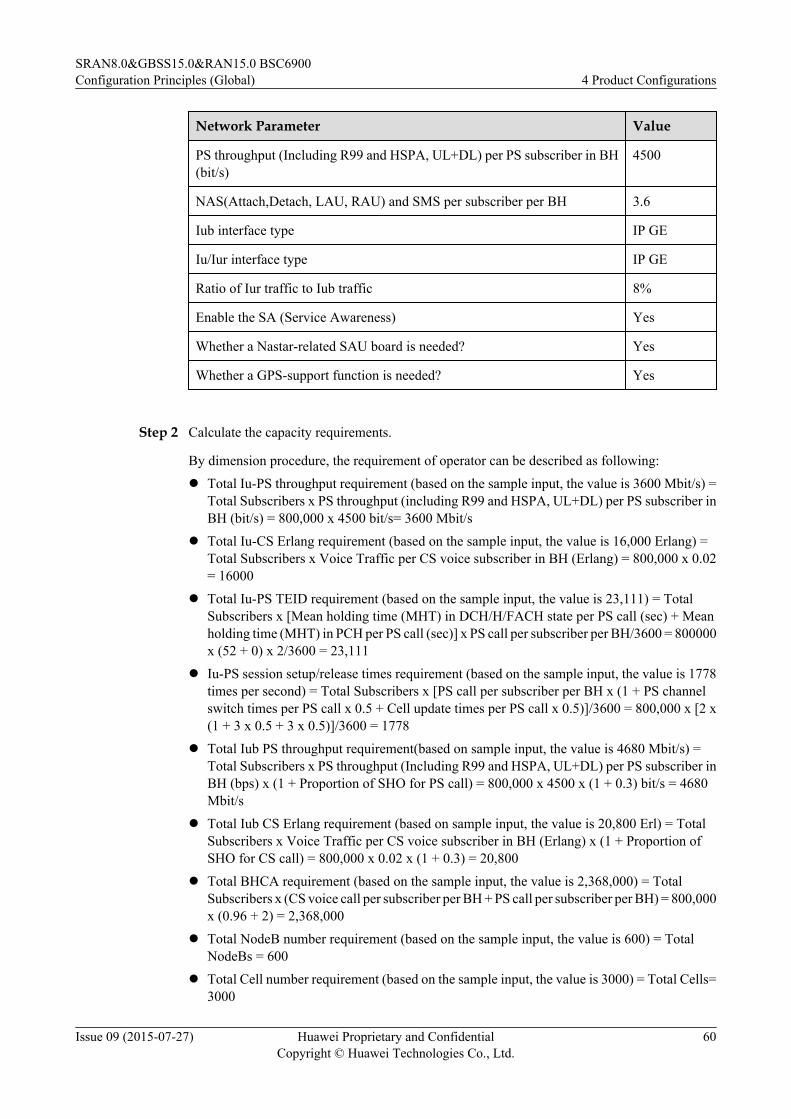
Network Parameter Value
PS throughput (Including R99 and HSPA, UL+DL) per PS subscriber in BH(bit/s)
4500
NAS(Attach,Detach, LAU, RAU) and SMS per subscriber per BH 3.6
Iub interface type IP GE
Iu/Iur interface type IP GE
Ratio of Iur traffic to Iub traffic 8%
Enable the SA (Service Awareness) Yes
Whether a Nastar-related SAU board is needed? Yes
Whether a GPS-support function is needed? Yes
Step 2 Calculate the capacity requirements.
By dimension procedure, the requirement of operator can be described as following:l Total Iu-PS throughput requirement (based on the sample input, the value is 3600 Mbit/s) =
Total Subscribers x PS throughput (including R99 and HSPA, UL+DL) per PS subscriber inBH (bit/s) = 800,000 x 4500 bit/s= 3600 Mbit/s
l Total Iu-CS Erlang requirement (based on the sample input, the value is 16,000 Erlang) =Total Subscribers x Voice Traffic per CS voice subscriber in BH (Erlang) = 800,000 x 0.02= 16000
l Total Iu-PS TEID requirement (based on the sample input, the value is 23,111) = TotalSubscribers x [Mean holding time (MHT) in DCH/H/FACH state per PS call (sec) + Meanholding time (MHT) in PCH per PS call (sec)] x PS call per subscriber per BH/3600 = 800000x (52 + 0) x 2/3600 = 23,111
l Iu-PS session setup/release times requirement (based on the sample input, the value is 1778times per second) = Total Subscribers x [PS call per subscriber per BH x (1 + PS channelswitch times per PS call x 0.5 + Cell update times per PS call x 0.5)]/3600 = 800,000 x [2 x(1 + 3 x 0.5 + 3 x 0.5)]/3600 = 1778
l Total Iub PS throughput requirement(based on sample input, the value is 4680 Mbit/s) =Total Subscribers x PS throughput (Including R99 and HSPA, UL+DL) per PS subscriber inBH (bps) x (1 + Proportion of SHO for PS call) = 800,000 x 4500 x (1 + 0.3) bit/s = 4680Mbit/s
l Total Iub CS Erlang requirement (based on sample input, the value is 20,800 Erl) = TotalSubscribers x Voice Traffic per CS voice subscriber in BH (Erlang) x (1 + Proportion ofSHO for CS call) = 800,000 x 0.02 x (1 + 0.3) = 20,800
l Total BHCA requirement (based on the sample input, the value is 2,368,000) = TotalSubscribers x (CS voice call per subscriber per BH + PS call per subscriber per BH) = 800,000x (0.96 + 2) = 2,368,000
l Total NodeB number requirement (based on the sample input, the value is 600) = TotalNodeBs = 600
l Total Cell number requirement (based on the sample input, the value is 3000) = Total Cells=3000
SRAN8.0&GBSS15.0&RAN15.0 BSC6900Configuration Principles (Global) 4 Product Configurations
Issue 09 (2015-07-27) Huawei Proprietary and ConfidentialCopyright © Huawei Technologies Co., Ltd.
60

l Total Active users requirement (based on sample input, the value is 39,111) = TotalSubscribers x [Mean holding time (MHT) in DCH/H/FACH state per PS call (sec) x PS callper subscriber per BH/3600 + Voice Traffic per CS voice subscriber in BH (Erlang)] =800000 x (52 x 2/3600 + 0.02) = 39,111
l Total Iub CID/UDP requirement(based on the sample input, the value is 124,800) = TotalSubscribers x {Mean holding time (MHT) in DCH/H/FACH state per PS call(sec) x PS callper subscriber per BH/3600 x [1 + 2 x (1+Proportion of SHO for PS call)] + Voice Trafficper CS voice subscriber in BH (Erlang) x 2 x (1 + Proportion of SHO for CS call)} = 800000x {52 x 2/3600 x [1 + 2 x (1 + 0.3)] + 0.02 x 2 x (1 + 0.3)} = 124,800Total Iub Session setup/release times requirement (based on the sample input, the value is10,951 times/s) = Total Subscribers x [PS call per subscriber per BH x (3 + Handover timesper PS call x 2 + PS channel switch times per PS call x 1 + Cell update times per PS call x0) + CS voice call per subscriber per BH x (2 + Handover times per CS call x 2)]/3600 =800000 x [2 x (3 + 5 x 2 + 3 x 1) + 0.96 x (2 + 8 x 2)]/3600 = 10,951
l Under this traffic model, the BHCA supported by each SPUc only board is 114,578:CP Load per subscriber (unit: CPU usage) = [CS voice call per subscriber per BH x (W1 +Handover times per CS call x W2) + PS call per subscriber per BH x (w3 + PS channel switchtimes per PS call x w7 + Cell update times per PS call x w8 + Handover times per PS call xw6) + NAS (Attach, Detach, LAU, RAU) and SMS per subscriber per BH x w9]/3600 =44.6%/3600 = 0.0124%Subscriber number supported by each SPUc board = (70%-10%) x 8/CP Load per subscriber= (70% - 10%) x 8/0.0124% = 38709BHCA capacity supported by each SPUc board = Subscriber number supported by one SPUcboard x (CS voice call per subscriber per BH + PS call per subscriber per BH) = 38709 x(0.96 + 2) = 114578.
l Under this traffic model, theactual PS throughput capacity supported by each DPUe boardis 470 Mbit/s.PS RAB mean data rate (UL+DL) (kbit/s) = [PS throughput (Including R99 and HSPA, UL+DL) per PS subscriber in BH (bit/s) x 3600/1000]/[PS call per subscriber per BH x Meanholding time (MHT) in DCH/H/FACH state per PS call (sec)]= 4,500 x 3600/1000/(2 x 52)= 155.8155.8 kbit/ ranges in [128, 196], PS Throughput Capacity per DPUe(Mbit/s) = 430 + (PSRAB Mean data rate - 128) x 1.47 =430 + (155.8 - 128) x 1.47 = 470 Mbit/s.
Step 3 Configure hardware and hardware capacity licenses. (HW69 R16 boards are used.)
1. Calculate the number of required DPUe boards and hardware capacity licenses.
Item Description Calculation of the Board Quantity
Iub PSthroughput
PS throughput over theIub interface
a' = Total Iub PS throughput requirement/Real PS throughput capacity supported byeach DPUe UP board = 4680/470 = 9.95
Iub CSTraffic
CS traffic over the Iubinterface
b' = Total Iub CS Erlang requirement /RealPS throughput(Mbit/s) supported by eachDPUe board = 20800/3350 = 6.21
SRAN8.0&GBSS15.0&RAN15.0 BSC6900Configuration Principles (Global) 4 Product Configurations
Issue 09 (2015-07-27) Huawei Proprietary and ConfidentialCopyright © Huawei Technologies Co., Ltd.
61

Item Description Calculation of the Board Quantity
Active users Number of active userssupported by the Iubinterface
n' = Total Active users requirement/Numberof active users supported by each DPUeboard = 39111/5880 = 6.65
Cell number Number of cellsmanaged by the RNC
c' = Total Cell quantity requirement /Numberof cells supported by each DPUe board =3000/300 = 10
DPUe boards work in N+1 board redundancy Mode.
N_ DPUe = ROUNDUP[Max(a' + b', n', c')] + 1 = ROUNDUP[Max(9.95+6.21, 10, 6.65 )]+ 1 = 18.
Calculation for hardware license:
Number of DPUes can be used for PS Throughput * 335Mbps(PS throughput capacitycontains in each DPUe board) = (18-6.21)*335Mbps = 3950 Mbps< Total Iub PSthroughput requirement(4680Mbps).
Therefore, hardware capacity licenses (165 Mbit/s) need to be configured.
N_165 = Min{N_ DPUe,ROUNDUP[(4680 - 3950)/165]} = 5.
3950+5*165 > 4680
Therefore, hardware capacity licenses (300 Mbit/s) are not required.
2. Calculate the number of required SPUb(SPUc) boards.
Item Description Calculation of the Board Quantity
BHCArequirement
BHCA required bythe network
Calculate the BHCA capacity of SPUb(SPUc)board in this traffic model.b' = Total BHCA requirement / BHCA capacitysupported by SPUb(SPUc) board =2368000/114582 = 20.67
Active users Number of activeusers supported onthe control plane
n' =Total Active users requirement / Number ofactive users supported by each pair of SPUb(SPUc) boards = 39111/9600 = 4.07
On-line users Number of onlineusers supported onthe control plane
m' = Total Online users requirement/ Number ofonline users supported by each pair of SPUb(SPUc) boards = 39111/24000 = 1.62
NodeBnumber
Number of NodeBsmanaged by theRNC
nb' = Total NodeB quantity requirement / Numberof NodeBs supported by each pair of SPUb(SPUc) boards = 600/180 = 3.33
Cell number Number of cellsmanaged by theRNC
c' = Total Cell quantity requirement /Number ofcells supported by each pair of SPUb(SPUc)boards = 3000/600 = 5
SRAN8.0&GBSS15.0&RAN15.0 BSC6900Configuration Principles (Global) 4 Product Configurations
Issue 09 (2015-07-27) Huawei Proprietary and ConfidentialCopyright © Huawei Technologies Co., Ltd.
62

SPUb(SPUc) boards are configured in active/standby mode.Number of SPUb(SPUc) boards (pair) = ROUNDUP(MAX(b', n', m', nb', c')) = ROUNDUP[Max (20.67, 4.07, 1.62, 3.33, 5)] = 21.
3. Calculate the number of required NIUa boards and QM1SNIU50M00s (NetworkIntelligence Throughput License).NIU boards are configured in load sharing mode by using a resource pool, and should beconfigured and N+1 redundancy.N_NIUa (pcs) = ROUNDUP(Total Iub PS Throughput requirement/PS throughput (Mbit/s) supported by each NIUa board) + 1 = ROUNDUP(4680 / 3200, 0 ) + 1 = 3.N_QM1SNIU50M00 = ROUNDUP[(Total Iub PS Throughput requirement - the PSThroughput capacity contained in NIUa board)/50(Mbit/s)]ROUNDUP[(4680 – 50)/50] =93.If the corresponding optional feature is not configured, N_NIUa=0.
4. Calculate the number of GOUc(GOUe) boards for the Iub interface.
Interface
Item CapacityRequirements
Calculation of the BoardQuantity
Iub Iub transmissiontype
GE Optical(IP)
Iub PSthroughput
ba = 4680Mbps.
ba' = Total Iub PS throughputrequirement / PS throughput (Mbit/s)supported by the GOUc(GOUe) inIub interface = 4680/2600=1.8
Iub CS Traffic bb = 20800 bb' = Total Iub CS Erlangrequirement /Erlang supported byeach GOUc(GOUe) board =20,800/18,000 = 1.16
NodeB number bn = 600 bn' = Total NodeB quantityrequirement /Number of NodeBssupported by each GOUc(GOUe)board = 600/500 = 1.2
Iub active users(CID/UDP)
an = 124800 an' = Total Iub CID/UDPrequirement /Iub UDP numbersupported by each GOUc(GOUe)board =124800/129000 = 0.97
Assuming GOUc(GOUe) boards are configured in active/standby mode,N_IUB_GOUc (pair) = ROUNDUP[Max(ba' + bb', bn', an')] = ROUNDUP[Max(1.8 +1.16, 1.2, 0.97)] = 3
5. Calculate the number of GOUc(GOUe) boards to be configured for the Iu/Iur interface.
SRAN8.0&GBSS15.0&RAN15.0 BSC6900Configuration Principles (Global) 4 Product Configurations
Issue 09 (2015-07-27) Huawei Proprietary and ConfidentialCopyright © Huawei Technologies Co., Ltd.
63

Interface
Item CapacityRequirements
Calculation of the BoardQuantity
Iu-CS Iu-CStransmissiontype
GE Optical(IP)
Iu-CS traffic cb = 16000 cb' = Total IuCS Erlang requirement/Traffic (Erl) supported by each GOUc(GOUe) board = 16,000/ 18,000 =0.89
Iu-PS Iu-PStransmissiontype
GE Optical(IP)
Iu-PS throughput pb = 3600. pb' = Total Iu PS throughputrequirement / PS throughput (Mbit/s)supported by the GOUc(GOUe) in Iu-PS interface = 3600/3200 = 1.13
IuPS on-lineusers
pu = 23111 pu' = Total Iu-PS on-line users/Iu-PSTEID supported by GOUc(GOUe)=23,111/200,000 = 0.12
Iu-PS session set-up and release
ps = 1778 ps' = ps/ Board specification =1778/5000 = 0.36
Assuming the PS and CS Iu interfaces and Iur interface are configured on the same GOUc(GOUe) board, and in active/standby mode,
N_IUIUR_GOUc (pair) = ROUNDUP[Max(pb' + cb', ps', pu') + (pb' + cb')*8%] =ROUNDUP[Max(1.13 + 0.89, 0.36, 0.12) + (1.13 + 0.89)*8%] = 3
N_GOUc (pair)= N_IUB_ GOUc + N_IUIUR_GOUc = 3+3 = 6.
6. Configure the SAU board.
Reserve a pair of slots for the SAU board. The default number of SAU board is 1 for EBC.
If a customer has purchased the OSS feature such as Nastar/SON and the SAU boards,instruct the customer configure one or two SAU board (N_SAU, the number of SAU isdecided by OSS according to the configured OSS features).
7. Configure the GCG board.
1 pair of GCGa(GCGb) boards.
8. Calculate the number of EPSs to be configured (QM1P00UEPS01).
Number of EPSs = ROUNDUP[(N_SPU(23*2) + N_DPUe(18) + N_Iub_GOUc(6*2) +N_IUIUR_GOUc(3*2) + N_NIUa(3) - 20) /26 ] = 3
Slots number of MPS besides fixed slots: 20. (28-2OMU-2GCU-2SCU-2SAU)
Slots number of EPS besides fixed slots: 26. (28 - 2SCU).
9. Calculate the number of required WP1B4PBCBN00s (Cabinets).
SRAN8.0&GBSS15.0&RAN15.0 BSC6900Configuration Principles (Global) 4 Product Configurations
Issue 09 (2015-07-27) Huawei Proprietary and ConfidentialCopyright © Huawei Technologies Co., Ltd.
64

Number of cabinets = ROUNDUP((Number of MPSs + Number of EPSs)/3) = ROUNDUP(4/3) = 1
The following table lists the configurations of the BSC6900 UMTS that adopts the HW69 R15hardware.
Item
Name Abbreviation Model Quantity
1 Cabinet WP1B4PBCBN00 2
2 Main Processing Subrack MPS QM1P00UMPS01 1
3 Extended Processing Subrack EPS QM1P00UEPS01 3
4 Clock board (pair) GCG WP1D000GCG01 1
5 Data Processing Unit DPUe WP1D000DPU03 18
6 Hardware Capacity License (165Mbit/s)
QM1SHW165M00 5
7 Hardware Capacity License (300Mbit/s)
QM1SHW300M00 0
8 Signaling Processing Unit (pair) SPUb QM1M000SPU01 21
9 Network Intelligence Unit NIUa WP1D000NIU00 3
10 Network Intelligence ThroughputLicense
QM1SNIU50M00 93
11 Iub Interface Board (Pair) GOUc WP1D000GOU01 3
12 Iu Interface Board (Pair) GOUc WP1D000GOU01 3
13 Signaling Access Unit SAUc None 1,2
To avoid the volume of inter-subrack data flows exceeding the limitation, service boards mustbe evenly deployed among subracks accordingly. The following figure shows a recommendedconfiguration.
SRAN8.0&GBSS15.0&RAN15.0 BSC6900Configuration Principles (Global) 4 Product Configurations
Issue 09 (2015-07-27) Huawei Proprietary and ConfidentialCopyright © Huawei Technologies Co., Ltd.
65
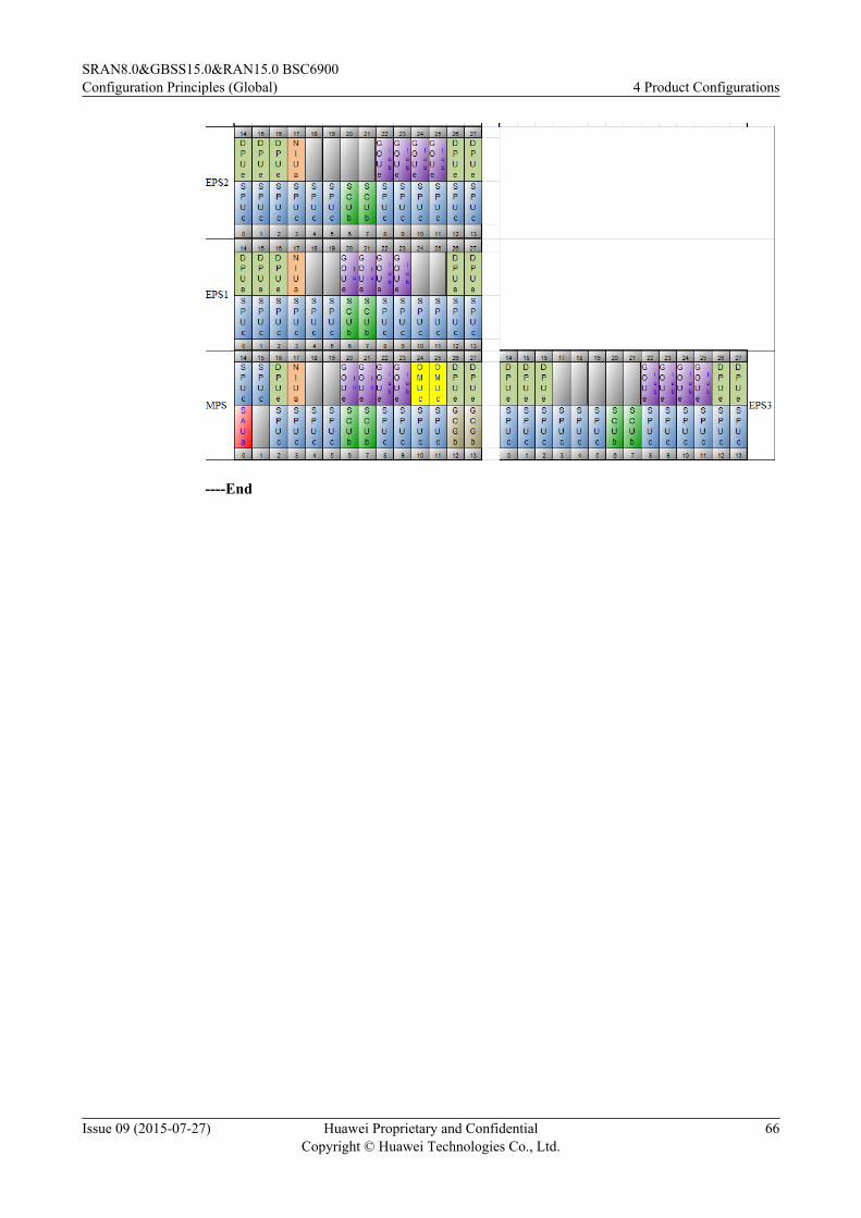
----End
SRAN8.0&GBSS15.0&RAN15.0 BSC6900Configuration Principles (Global) 4 Product Configurations
Issue 09 (2015-07-27) Huawei Proprietary and ConfidentialCopyright © Huawei Technologies Co., Ltd.
66

5 Expansion and Upgrade Configurations
About This Chapter
5.1 BSC6900 GSM Hardware Expansion and Upgrade Configurations Example
5.2 BSC6900 UMTS Hardware Expansion and Upgrade Configurations
5.3 BSC6900 GU Hardware Expansion and Upgrade Configurations
SRAN8.0&GBSS15.0&RAN15.0 BSC6900Configuration Principles (Global) 5 Expansion and Upgrade Configurations
Issue 09 (2015-07-27) Huawei Proprietary and ConfidentialCopyright © Huawei Technologies Co., Ltd.
67

5.1 BSC6900 GSM Hardware Expansion and UpgradeConfigurations Example
Capacity expansion can be performed through the following methods:
1. Improving the service processing capability of the system through hardware expansion.2. Improving the service processing capability of the system by configuring hardware capacity
licenses.
The two methods can be adopted separately or together based on the traffic model and trafficrequirements of the network.
5.1.1 Hardware Expansion and Upgrade ConfigurationsTwo types of board can be used to support the same functions or transmission mode. For example,to implement TDM over STM-1 on the Abis interface, OIUb and POUc boards can be installed.This is known as mixed insertion of boards. The following table lists the HW60 R8, HW69 R11,HW69 R13, and HW69 R15 boards.
HardwareVersion
Board
HW60 R8 DPUc, DPUd, XPUa, SCUa, TNUa, GCUa, OMUb, EIUa, FG2a, GOUa,OIUa, PEUa
HW69 R11 DPUc, DPUd, XPUb, SCUa, TNUa, GCUa, GCGa, OMUa,EIUa, FG2c,GOUc, OIUa, PEUa, POUc
HW69 R13 DPUf, DPUg, XPUb, SCUb, TNUa, GCUa, GCGa,OMUc,EIUa, FG2c,GOUc, PEUa, POUc, SAUc, NIUa
HW69 R15 DPUf, DPUg, XPUc, SCUb, TNUb, GCUb, GCGb, OMUc, EIUb, OIUb,FG2c, GOUe, PEUc, POUc, SAUc, NIUa
NOTE
TNUb was supported at V900R15SPC560.
In HW69 R15, XPUb is replaced by XPUc,EIUa is replaced by EIUb, OIUa is replaced by OIUb,and PEUa is replaced by PEUc, GOUc is replaced by GOUe,but the board specifications are notchanged. Therefore, the configuration principle and capacity expansion principle of XPUc,EIUb,OIUb, PEUc,GOUe remain the same as XPUb,EIUa, OIUa, PEUa, GOUc.
l BM Configuration
SRAN8.0&GBSS15.0&RAN15.0 BSC6900Configuration Principles (Global) 5 Expansion and Upgrade Configurations
Issue 09 (2015-07-27) Huawei Proprietary and ConfidentialCopyright © Huawei Technologies Co., Ltd.
68

Model Name BM/TC Combined Configuration Mode
WP1D000FG201 FG2c 1. Number of WP1D000FG201s as A interfaceboards = 2 x ROUNDUP ((MaxACICPerBSCIP –Number of FG2a boards supported by the Ainterface/2 x ACICPerFG2a)/ACICPerFG2c), 0)NOTE
The quantity depends on the number of ports and thenumber of equivalent CIC circuits on the A interface. Incapacity expansion scenarios, the capacity specificationsand number of ports supported by the existing FG2aboards must be subtracted from the total requiredcapacity.
2. Number of WP1D000FG201s as Abis interfaceboards = 2 x ROUNDUP ((MAX (ROUNDUP(AbisIPFEGENo/GEPortPerFG2c, 0) xGEPortPerFG2c – Number of FG2a boardssupported by the Abis interface/2 xGEPortPerFG2a)/GEPortPerFG2c,(TRXNoFEGE – Number of FG2a boardssupported by the Abis interface/2 xTRXNoPerFG2a)/TRXNoPerFG2c), 0)NOTE
When the Abis interface does not use IP transmission andUm interface soft synchronization is not enabled betweendifferent BSCs, a pair of S4020192 boards is configuredby default.
When the Abis interface uses IP transmission, the Abisinterface boards must be configured. The number ofrequired Abis interface boards depends on the number ofFE/GE ports and the number of TRXs. In capacityexpansion scenarios, the originally supported TRXs mustbe subtracted from the total required TRXs. In addition,the number of ports supported before capacity expansionshould also be considered.
3. Number of WP1D000FG201s as Gb interfaceboards = 2 x ROUNDUP ((MAX (ROUNDUP(MAX (GbIPFEGENo/GEPortPerFG2c, 0) xGEPortPerFG2c – Number of FG2a boards overGb interface/2 x GEPortPerFG2a)/GEPortPerFG2c), (GbIPTputPerBSC – Number ofFG2a boards over Gb interface/2 x(GbTputPerFG2a/1024))/GbTputPerFG2c/1024),0)NOTE
When the built-in PCU is used, Gb interface boards mustbe configured. The number of required Gb interfaceboards depends on the number of ports and the traffic onthe Gb interface. The originally supported traffic must besubtracted from the total supported traffic.
SRAN8.0&GBSS15.0&RAN15.0 BSC6900Configuration Principles (Global) 5 Expansion and Upgrade Configurations
Issue 09 (2015-07-27) Huawei Proprietary and ConfidentialCopyright © Huawei Technologies Co., Ltd.
69

Model Name BM/TC Combined Configuration Mode
4. The number of FG2c boards to be configured isequal to the total number of all the precedingboards.
SRAN8.0&GBSS15.0&RAN15.0 BSC6900Configuration Principles (Global) 5 Expansion and Upgrade Configurations
Issue 09 (2015-07-27) Huawei Proprietary and ConfidentialCopyright © Huawei Technologies Co., Ltd.
70

Model Name BM/TC Combined Configuration Mode
WP1D000GOU03 GOUe 1. Number of A interface boards :Number of WP1D000GOU01s as A interfaceboards = 2 x ROUNDUP (((MaxACICPerBSCIP –Number of GOUa boards as A interface boards/2 xACICPerFG2a)/ACICPerFG2c), 0)Number of WP1D000GOU03s as A interfaceboards = 2 x ROUNDUP (((MaxACICPerBSCIP –Number of GOUa boards as A interface boards/2 xACICPerFG2a)/ACICPerFG2c - Number ofGOUc boards as A interface boards/2), 0)NOTE
The quantity depends on the number of ports and thenumber of equivalent CIC circuits on the A interface. Incapacity expansion scenarios, the configuration quantityequals the calculated number minus the board capacityspecifications and port number before capacityexpansion.
2. Number of Abis interface boards :Number of WP1D000GOU01s as Abis interfaceboards = 2 x ROUNDUP((MAX(ROUNDUP(AbisIPFEGENo/GEPortPerGOUc, 0) xGEPortPerGOUc – Number of GOUa boards asAbis interface boards/2 x GEPortPerGOUa)/GEPortPerGOUc, (TRXNoFEGE – Number ofGOUa boards as Abis interface boards/2 xTRXNoPerFG2a)/TRXNoPerFG2c), 0)Number of WP1D000GOU03s as Abis interfaceboards = 2 x ROUNDUP((MAX(ROUNDUP(AbisIPFEGENo/GEPortPerGOUe, 0) xGEPortPerGOUe – Number of GOUa boards asAbis interface boards/2 x GEPortPerGOUa -Number of GOUc boards as Abis interface boards/2 x GEPortPerGOUc)/GEPortPerGOUe,(TRXNoFEGE - Number of GOUa boards as Abisinterface boards/2 x TRXNoPerGOUa - Number ofGOUc boards as Abis interface boards/2 xTRXNoPerFG2c)/TRXNoPerFG2c), 0)NOTE
When IP transmission is used on the Abis interface, thisboard should be configured. The configuration quantitydepends on the number GE ports and the number ofTRXs. In capacity expansion scenarios, the configurationquantity equals the calculated quantity minus the numberof originally supported TRXs. In addition, the number ofports supported before capacity expansion should also beconsidered.
3. Number of Gb interface boards:Number of WP1D000GOU01s as Gb interfaceboards = 2 x ROUNDUP(MAX(GbIPGEOpticNo/
SRAN8.0&GBSS15.0&RAN15.0 BSC6900Configuration Principles (Global) 5 Expansion and Upgrade Configurations
Issue 09 (2015-07-27) Huawei Proprietary and ConfidentialCopyright © Huawei Technologies Co., Ltd.
71

Model Name BM/TC Combined Configuration Mode
GEPortPerGOUc, GbIPTputPerBSC/GbTputPerFG2c/1024), 0)Number of WP1D000GOU03s as Gb interfaceboards = 2 x ROUNDUP(MAX(GbIPGEOpticNo/GEPortPerGOUe, GbIPTputPerBSC/GbTputPerFG2c/1024), 0)NOTE
When a built-in PCU is used, Gb interface boards shouldbe configured. The configuration quantity depends on thenumber of ports and the traffic on the Gb interface.Generally, only GOUc and GOUe boards support Gbover GE.
4. The quantity to be configured is equal to the totalnumber of all the preceding boards.
SRAN8.0&GBSS15.0&RAN15.0 BSC6900Configuration Principles (Global) 5 Expansion and Upgrade Configurations
Issue 09 (2015-07-27) Huawei Proprietary and ConfidentialCopyright © Huawei Technologies Co., Ltd.
72

Model Name BM/TC Combined Configuration Mode
WP1D000POU01 POUc 1. Number of WP1D000POU01s as A interfaceboards (TDM transmission) = 2 x ROUNDUP((MaxACICPerBSCTDM – Number of OIUa andOIUb boards as A interface boards/2 xACICPerOIUa)/ACICPerPOUcTDM, 0)
2. Number of WP1D000POU01s as Ater interfaceboards (TDM transmission) = 2 x ROUNDUP((MaxAterCICPerBSC – Number of OIUa andOIUb boards as Ater interface boards/2 xAterCICPerOIUa)/AterCICPerPOUcTDM, 0)
3. Number of WP1D000POU01s as Abis interfaceboards (TDM transmission) = 2 x ROUNDUP(MAX(AbisTDMSTM1No/STM1PortPerPOUc,TRXNoTDMSTM1/TRXHRPerPOUcTDM), 0)NOTE
The quantity depends on the number of ports and thenumber of TRXs on the Abis interface. An E1 port (whichcan be shared in cascading networking) must beconfigured for each base station by default.
4. Number of WP1D000POU01s as A interfaceboards (IP transmission) = 2 x ROUNDUP(MAX(MaxACICPerBSCIP/ACICPerPOUcIP), 0)NOTE
The quantity depends on the number of CIC circuits onthe A interface.
5. Number of WP1D000POU01s as Abis interfaceboards (IP transmission) = 2 x ROUNDUP(MAX(SiteNoIPSTM1/STM1PortPerPOUc/63,AbisIPSTM1No/STM1PortPerPOUc,TRXNoIPSTM1/TRXPerPOUcIP), 0)NOTE
When IP transmission is used on the Abis interface, thisboard should be configured. The configuration quantitydepends on the number of base stations, the number ofports, and the number of TRXs. An E1 port must beconfigured for each base station by default.
6. Number of WP1D000GOU01s as Gb interfaceboards = 2 x ROUNDUP(MAX(GbFRSTM1No/STM1PortPerPOUc, GbFRTputPerBSC/GbTputPerPOUcFR/1024), 0)NOTE
When a built-in PCU is used, Gb interface boards shouldbe configured. The configuration quantity depends on thenumber of ports and the traffic on the Gb interface.
7. The quantity is equal to the total number of all thepreceding boards.
SRAN8.0&GBSS15.0&RAN15.0 BSC6900Configuration Principles (Global) 5 Expansion and Upgrade Configurations
Issue 09 (2015-07-27) Huawei Proprietary and ConfidentialCopyright © Huawei Technologies Co., Ltd.
73

Model Name BM/TC Combined Configuration Mode
NOTEIn scenarios of capacity expansion, the configuration quantityequals the calculated number minus the OIUa and OIUbboard capacity specifications on the Ater and Abis interfaces.
SRAN8.0&GBSS15.0&RAN15.0 BSC6900Configuration Principles (Global) 5 Expansion and Upgrade Configurations
Issue 09 (2015-07-27) Huawei Proprietary and ConfidentialCopyright © Huawei Technologies Co., Ltd.
74

Model Name BM/TC Combined Configuration Mode
WP1D000EIU01 EIUb The EIUb has the same capacity with the EIUa, so thatthe EIUb inherits the configuration and capacityexpansion principles of the EIUa.1. Number of Ater interface boards = 2 x ROUNDUP
(MaxAterCICPerBSC/AterCICPerEIUa, 0)NOTE
The quantity depends on the number of CIC circuits onthe Ater interface. In the new site deployment scenario,MaxAterCICPerBSC indicates the required number ofCIC circuits on the Ater interface.
In the capacity expansion scenario, MaxAterCICPerBSCindicates the additional number of CIC circuits on theAter interface.
2. Number of Abis interface boards = 2 x ROUNDUP((MAX(SiteNoTDME1/E1PortPerEIUa,AbisTDME1No/E1PortPerEIUa,TRXNoTDME1/TRXFRPerEIUa),(SiteNoTDME1 x ROUNDUP((1+TRXNoPerSite)/LAPDMuxRate/255,0))),0)+IF(AND(or((TRXNoHDLCE1=0),(TRXNoIPE1=0),TRXNoHDLCSTM1=0,TRXNoIPSTM1=0, Semi_PermanentNum=0)),0,2)NOTE
The quantity depends on the number of sites, ports andTRXs on the Abis interface.Each NodeB must beseparately configured with one E1 port by default. E1ports on different NodeBs can be cascaded in networkingdeployment.
In the capacity expansion scenario, SiteNoTDME1,AbisTDME1No, and TRXNoTDME1 indicate thenumber of NodeBs, ports, and TRXs, respectively.
Another two Abis interface boards are needed ifmonitoring time slots are configured on the NodeB tooptimize the transmission efficiency.
LAPDMuxRate indicates the LAPD multiplex ratio, therange of which is (1:1,2:1,3:1,4:1,5:1,6:1).
3. Number of Pb interface boards = 2 x ROUNDUP(MAX (PbTDME1No/E1PortPerEIUa, 0))NOTE
The Pb interface board in configured only when the PCUis installed externally. The number of Pb interface boardsdepends on the number of ports.In the capacity expansionscenario, PbTDME1No indicates the additional numberof ports.
4. The number of EIUbc boards to be configured isequal to the total number of all the precedingboards.
SRAN8.0&GBSS15.0&RAN15.0 BSC6900Configuration Principles (Global) 5 Expansion and Upgrade Configurations
Issue 09 (2015-07-27) Huawei Proprietary and ConfidentialCopyright © Huawei Technologies Co., Ltd.
75

Model Name BM/TC Combined Configuration Mode
WP1D000OIU01 OIUb The OIUb has the same capacity with the OIUa, so thatthe OIUb inherits the configuration and capacityexpansion principles of the OIUa.1. Number of Ater interface boards = 2 x ROUNDUP
(MaxAterCICPerBSC/AterCICPerOIUa, 0)NOTE
The quantity depends on the number of CIC circuits onthe Ater interface.In the capacity expansion scenario,MaxAterCICPerBSC indicates the additional number ofCIC circuits on the Ater interface.
2. Number of Abis interface boards = 2 x ROUNDUP(MAX (AbisTDMSTM1No/STM1PortPerOIUa,TRXNoTDMSTM1/TRXHRPerOIUa),0)NOTE
The quantity depends on the number of ports and thenumber of TRXs on the Abis interface.In the capacityexpansion scenario, AbisTDMSTM1No indicates theadditional number of ports and TRXNoTDMSTM1indicates the additional number of TRXs.
Each NodeB must be separately configured with one E1port by default. E1 ports on different NodeBs can becascaded in networking deployment.
3. Number of Pb interface boards = 2 x ROUNDUP(MAX (PbTDME1No/E1PortPerOIUa, 0))In the capacity expansion scenario,PbTDMSTM1No indicates the additional numberof ports.
4. The number of OIUb boards to be configured isequal to the total number of all the preceding boards
NOTEIn RAN13.0 and later versions, all OIUa boards are replacedby POUc boards. So OIUb boards are replaced by POUcboards too. POUc is recommend.
SRAN8.0&GBSS15.0&RAN15.0 BSC6900Configuration Principles (Global) 5 Expansion and Upgrade Configurations
Issue 09 (2015-07-27) Huawei Proprietary and ConfidentialCopyright © Huawei Technologies Co., Ltd.
76

Model Name BM/TC Combined Configuration Mode
WP1D000PEU01 PEUc The PEUc has the same capacity with the PEUa, so thatthe PEUa inherits the configuration and capacityexpansion principles of the PEUa.1. Number of A interface boards = 2 x ROUNDUP
(MaxACICPerBSCIP/ACICperPEUaIP,0)NOTE
The board quantity depends on the number of CICcircuits. In the capacity expansion scenario,MaxACICPerBSCIP indicates the additional number ofCIC circuits on the Ater interface.
2. Number of Abis interface boards (IP) = 2 xROUNDUP(MAX(SiteNoIPE1/E1PortPerPEUa,AbisIPE1No/(E1PortPerPEUa-IF((Semi_PermanentNum=0),0,1)),TRXNoIPE1/TRXPerPEUaIP),0)NOTE
The Abis interface board is configured when the IPtransmission mode is used. The number of Abis interfaceboards depends on the number of ports and TRXs. Bydefault, each NodeB is separately configured with one E1port.
In the capacity expansion scenario, SiteNoIPE1,AbisIPE1No, and TRXNoIPE1 indicate the number ofNodeBs, ports, and TRXs, respectively.
32 E1/T1 interfaces are configured on each pair of boardsif monitoring time slots are configured on the NodeBusing IP over E1.
Otherwise, 31 E1/T1 interfaces are configured.
3. Number of required Gb interface boards =2 xROUNDUP(MAX(GbFRE1No/E1PortPerPEUa,GbFRTputPerBSC/GbTputPerPEUaFR/1024),0)NOTE
When the built-in PCU is used, Gb interface boards mustbe configured.The number of required Gb interfaceboards depends on the number of ports and the traffic onthe Gb interface.
In the network expansion scenario, GbFRE1No andGbFRTputPerBSC indicate the additional number of Gbinterfaces and traffic volume over the Gb interface,respectively.
4. The number of PEUc boards to be configured isequal to the total number of all the precedingboards.
SRAN8.0&GBSS15.0&RAN15.0 BSC6900Configuration Principles (Global) 5 Expansion and Upgrade Configurations
Issue 09 (2015-07-27) Huawei Proprietary and ConfidentialCopyright © Huawei Technologies Co., Ltd.
77

Model Name BM/TC Combined Configuration Mode
WP1D000XPU03 XPUc 1. If the number of eGBTS TRX is not enlarged (OnlyGBTS TRX enlarged):Number of required XPUc= 2 x ROUNDUP(MAX((Number of TRXs after capacity expansion -Number of TRXs for XPUa boards)/640, (Numberof BHCA enlarged - Number of BHCA for XPUaboards)/1050000, (Number of ERL enlarged -Number of ERL for XPUa boards)/3900), 0)NOTE
If the IBCA function is enabled in the live network, thenumber of WP1D000XPU03s used for the IBCAfunction will be subtracted from the quantity beforecapacity expansion.
Number of TRXs for XPUa boards: The maximumnumber of TRXs is determined based on the number ofpairs of XPUa boards. The mapping between the numberof pairs of XPUa boards and the number of TRXs is asfollows:
1: 270; 2: 630; 3: 990; 4: 1350; 5: 1710; 6: 2070.
Number of BHCA for XPUa boards: The maximumnumber of BHCA is determined based on the number ofpairs of XPUa boards. The mapping between the numberof pairs of XPUa boards and the number of BHCA is asfollows:
1: 492000; 2: 1148000; 3: 1804000; 4: 2460000; 5:3116000; 6: 3772000.
Number of ERL for XPUa boards: The maximum numberof BHCA is determined based on the number of pairs ofXPUa boards. The mapping between the number of pairsof XPUa boards and the number of BHCA is as follows:
1: 1720; 2: 4020; 3: 6320; 4: 8620; 5: 10920; 6: 13220.
2. If the number of eGBTS TRX is enlarged:Number of required XPUc = 2 x ROUNDUP(MAX((Number of TRXs after capacity expansion -Number of TRXs for XPUa boards)/640, (Numberof BHCA enlarged - Number of BHCA for XPUaboards) x Number of GBTS TRX enlarged/Numberof TRX enlarged /1050000 + (Number of BHCAenlarged - Number of BHCA for XPUa boards) xNumber of eGBTS TRX enlarged/Number of TRXenlarged/950000, (Number of ERL enlarged -Number of ERL for XPUa boards)/3900), 0)
SRAN8.0&GBSS15.0&RAN15.0 BSC6900Configuration Principles (Global) 5 Expansion and Upgrade Configurations
Issue 09 (2015-07-27) Huawei Proprietary and ConfidentialCopyright © Huawei Technologies Co., Ltd.
78

Model Name BM/TC Combined Configuration Mode
NOTENumber of TRXs for XPUa boards: The maximumnumber of TRXs is determined based on the number ofpairs of XPUa boards. The mapping between the numberof pairs of XPUa boards and the number of TRXs is asfollows:
1: 270; 2: 630; 3: 990; 4: 1350; 5: 1710; 6: 2070.
Number of BHCA for XPUa boards: The maximumnumber of BHCA is determined based on the number ofpairs of XPUa boards. The mapping between the numberof pairs of XPUa boards and the number of BHCA is asfollows:
1: 492000 x Number of GBTS TRX enlarged/Number ofTRX enlarged + 492000 x Number of eGBTS TRXenlarged/Number of TRX enlarged
2: 1148000 x Number of GBTS TRX enlarged/Numberof TRX enlarged + 1148000 x Number of eGBTS TRXenlarged/Number of TRX enlarged
3: 1804000 x Number of GBTS TRX enlarged/Numberof TRX enlarged + 1804000 x Number of eGBTS TRXenlarged/Number of TRX enlarged
4: 2460000 x Number of GBTS TRX enlarged/Numberof TRX enlarged + 2460000 x Number of eGBTS TRXenlarged/Number of TRX enlarged
5: 3116000 x Number of GBTS TRX enlarged/Numberof TRX enlarged + 3116000 x Number of eGBTS TRXenlarged/Number of TRX enlarged
6: 3772000 x Number of GBTS TRX enlarged/Numberof TRX enlarged + 3772000 x Number of eGBTS TRXenlarged/Number of TRX enlarged
Number of ERL for XPUs: The maximum number ofBHCA is determined based on the number of pairs ofXPU boards. The mapping between the number of pairsof XPU boards and the number of BHCA is as follows:
1: 1720; 2: 4020; 3: 6320; 4: 8620; 5: 10920; 6: 13220.
If "Number of required WP1D000XPU03s" <= 0,then there is no need to add XPUc board.
3. If the IBCA function will be used, one more pair ofXPUc boards should be used as XPUI.
WP1D000NIU00 NIUa Configure this board only when intelligent serviceidentification is required. If intelligent serviceidentification is enabled, the number of requiredWP1D000NIU00s is one.
SRAN8.0&GBSS15.0&RAN15.0 BSC6900Configuration Principles (Global) 5 Expansion and Upgrade Configurations
Issue 09 (2015-07-27) Huawei Proprietary and ConfidentialCopyright © Huawei Technologies Co., Ltd.
79

Model Name BM/TC Combined Configuration Mode
WP1D000DPU05 DPUf 1. In BM/TC separated configuration mode (or TDM/IP hybrid transmission in A over IP)On the BM side:The number of DPUf to be configured depends onthe number of CIC circuits that require IWFconversion between TDM and IP and between IPand IP.Number of DPUf = RoundUp( MAXIWF-PerBSCTDMIP / IWFNoPerDPUfTDMIP + MAX(MAXIWFPerBSCIPIP - MAXIWFPerBSCTD-MIP, 0) / IWFNoPerDPUfIPIP,0)+1On the TC side:Number of DPUf = RoundUp(MaxACIC-PerBSCTDM/TCNoPerDPUf) +1
2. In BM/TC combined configuration mode (or TDM/IP hybrid transmission in A over IP)The DPUf providing the TC function can supportthe IWF function of the same specifications asDPUf.Extra DPUf should be configured to provide theIWF function for the A-interface CIC circuits in Aover IP transmission.Number of DPUf = RoundUp(MaxACIC-PerBSCTDM/ TCNoPerDPUf,0) + RoundUp( MAXIWFPerBSCTDMIP / IWFNoPerDPUfTD-MIP + MAX (MAXIWFPerBSCIPIP -MAXIWFPerBSCTDMIP, 0) /IWFNoPerDPUfIPIP,0)+1
3. A over IP:The number of DPUf to be configured depends onthe number of CIC circuits that require IWFconversion between TDM and IP and between IPand IP.Number of DPUf = RoundUp(MAXIWFPerBSCTDMIP / IWFNoPerDPUfTD-MIP + MAX (MAXIWFPerBSCIPIP -MAXIWFPerBSCTDMIP, 0) /IWFNoPerDPUfIPIP,0) +1
4. IP transmission on all interfaces of the BSC6900GSMNumber of DPUf = RoundUp(MaxACICPerBSCIP / IWFNoPerDPUfIPIP,0) +1
SRAN8.0&GBSS15.0&RAN15.0 BSC6900Configuration Principles (Global) 5 Expansion and Upgrade Configurations
Issue 09 (2015-07-27) Huawei Proprietary and ConfidentialCopyright © Huawei Technologies Co., Ltd.
80

Model Name BM/TC Combined Configuration Mode
WP1D000DPU06 DPUg Number of required WP1D000DPU06s = ROUNDUP(MaxPDCHPerBSC/PDCHNoPerDPUg, 0) + 1 –Number of DPUd boardsNOTE
This module must be configured when the built-in PCU isused. The configuration quantity depends on the maximumnumber of PDCHs required by the BSC. WP1D000DPU06works in N+1 backup mode.
The DPUg and DPUd boards have identicalspecifications.
GMIPEPRACK00 GEPS 1. Total number of interface boards = EIUa + EIUb +OIUa + OIUb + PEUa + PEUc + POUc + FG2a +GOUa + FG2c + GOUc
2. Total number of user plane boards = XPUa + DPUc+ DPUd + DPUf + DPUg + XPUb
Number of processing subracks = ROUNDUP(MAX(Total number of interface boards – 10/14, (Totalnumber of interface boards + Total number of userplane boards – 18)/24, 0))
QM1B0PBCBN00 Cabinet
Number of cabinets = (Number of GMPSs + Numberof GEPSs)/3
Multiple transmission modes, such as TDM, HDLC, and IP, can be used on the Abisinterface within one BSC.
l TC ConfigurationThe following table describes the configurations of each module.
SRAN8.0&GBSS15.0&RAN15.0 BSC6900Configuration Principles (Global) 5 Expansion and Upgrade Configurations
Issue 09 (2015-07-27) Huawei Proprietary and ConfidentialCopyright © Huawei Technologies Co., Ltd.
81

Model Name BM/TC Combined Configuration Mode
WP1D000EIU01
EIUb The EIUb has the same capacity with the EIUa, so thatthe EIUb inherits the configuration and capacityexpansion principles of the EIUa.1. Number of Ar interface boards = 2 x ROUNDUP
(MaxACICPerBSCTDM / ACICPerEIUa, 0)NOTE
The quantity depends on the number of CIC circuits on theA interface. In the capacity expansion scenario,MaxACICPerBSCTDM indicates the additional number ofCIC circuits on the A interface.
2. Number of Ater interface boards = 2 x ROUNDUP(MaxAterCICPerBSC/AterCICPerEIUa, 0)NOTE
The quantity depends on the number of CIC circuits on theAter interface. In the new site deployment scenario,MaxAterCICPerBSC indicates the required number of CICson the Ater interface.
In the capacity expansion scenario, MaxAterCICPerBSCindicates the additional number of CICs on the Aterinterface.
3. The number of EIUb boards to be configured is equalto the total number of all the preceding boards.
WP1D000OIU01
OIUb The OIUb has the same capacity with the OIUa, so thatthe OIUb inherits the configuration and capacityexpansion principles of the OIUa.1. Number of Ar interface boards = 2 x ROUNDUP
(MaxACICPerBSCTDM / ACICPerOIUa, 0)NOTE
The quantity depends on the number of CIC circuits on theA interface. In the capacity expansion scenario,MaxACICPerBSCTDM indicates the additional number ofCIC circuits on the A interface.
2. Number of Ater interface boards = 2 x ROUNDUP(MaxAterCICPerBSC/AterCICPerOIUa, 0)NOTE
The quantity depends on the number of CIC circuits on theAter interface. In the capacity expansion scenario,MaxAterCICPerBSC indicates the additional number ofCIC circuits on the Ater interface.
3. The number of OIUb boards to be configured is equalto the total number of all the preceding boards
NOTEIn RAN13.0 and later versions, all OIUa boards are replaced byPOUc boards.
SRAN8.0&GBSS15.0&RAN15.0 BSC6900Configuration Principles (Global) 5 Expansion and Upgrade Configurations
Issue 09 (2015-07-27) Huawei Proprietary and ConfidentialCopyright © Huawei Technologies Co., Ltd.
82

Model Name BM/TC Combined Configuration Mode
WP1D000PEU01
PEUc The PEUc has the same capacity with the PEUa, so thatthe PEUa inherits the configuration and capacityexpansion principles of the PEUa.Number of Ar interface boards = 2 x ROUNDUP(MaxACICPerBSCTDM / ACICIperPEUcIPACICPer-EIUa, 0)NOTE
The quantity depends on the number of CIC circuits on the Ainterface. In the capacity expansion scenario,MaxACICPerBSCTDM indicates the additional number of CICcircuits on the A interface.
WP1D000POU01
POUc 1. Number of WP1D000POU01s as A interface boards(TDM transmission) = 2 x ROUNDUP((MaxACIC-PerBSCTDM – Number of OIUa and OIUb boards asA interface boards/2 x ACICPerOIUa)/ACICPerPOUcTDM, 0)
2. Number of WP1D000POU01s as Ater interfaceboards (TDM transmission) = 2 x ROUNDUP((MaxAterCICPerBSC – Number of OIUa and OIUbboards as Ater interface boards/2 xAterCICPerOIUa)/AterCICPerPOUcTDM, 0)When a built-in PCU is used, Gb interface boardsshould be configured. The configuration quantitydepends on the number of ports and the traffic on theGb interface.
3. The quantity is equal to the total number of all thepreceding boards.
NOTEIn other scenarios of capacity expansion, the configurationquantity equals the calculated number minus the OIUa and OIUbboard capacity specifications on the Ater and Abis interfaces.
WP1D000DPU05
DPUf WP1D000DPU05 provides only the TC function.Number of required WP1D000DPU05s = ROUNDUP((MaxACICPerBSC – (DPUc – 1) x TCNoPerDPUc)/TCNoPerDPUf, 0)
GMIPEPRACK00
GEPS 1. Total number of interface boards = EIUa + EIUb +OIUa + OIUb + POUc
2. Total number of user plane boards = DPUc + DPUf3. Number of processing subracks = ROUNDUP(MAX
(Total number of interface boards/14, (Total numberof interface boards + Total number of user planeboards)/24, 0))
QM1B0PBCBN00
Cabinet Number of cabinets = (Number of GMPSs + Number ofGEPSs)/3
SRAN8.0&GBSS15.0&RAN15.0 BSC6900Configuration Principles (Global) 5 Expansion and Upgrade Configurations
Issue 09 (2015-07-27) Huawei Proprietary and ConfidentialCopyright © Huawei Technologies Co., Ltd.
83

5.1.2 Hardware Capacity License ExpansionN/A
5.1.3 Examples of Hardware Expansionl Total Replacement
An operator may want to increase equipment integration and achieve a larger capacity withexisting cabinets and subracks. In this case, a total replacement is recommended.In a total replacement, the capacity is considered first. The Unistar quotation template isused to work out a BSC equipment list based on the specifications of the new hardwareversion. The boards required for the capacity expansion are determined through acomparison with existing boards that can be reused. Boards that cannot be reused need tobe removed.The procedure for a total replacement is as follows:
Step 1 Fill in the Unistar calculation table and calculate the configuration required after the capacityexpansion.
Step 2 Record the board and equipment configurations before the capacity expansion.
Step 3 The components required in the capacity expansion are the components after the capacityexpansion minus those before the capacity expansion.
Item Name ConfigurationBefore theCapacityExpansion
ConfigurationAfter theCapacityExpansion
Number ofComponentsto Be Added
1 Subracks (MPS, EPS) A1 B1 B1 – A1
2 Data Processing Units(DPUf)
A2 B2 B2 – A2
3 Data Processing Units(DPUc, DPUg)
A3 B3 B3 – A3
4 Extended ProcessingUnits (XPUb)
A4 B4 B4 – A4
5 Interface boards A5 B5 B5 – A5
6 Cabinets A6 B6 B6 – A6
In this scenario, different versions require different points for attention.
In a capacity expansion for HW69 R11, XPUa, FG2a, and GOUa boards cannot be reused. If IPinterface boards are used only for the Gb interface and TDM networking is used on the entirenetwork, FG2a and GOUa boards over the Gb interface can be regarded as FG2c boards. FG2a,GOUa, and FG2c boards have no difference in terms of supporting small-capacity Gb interfaces.
In a capacity expansion for HW69 R13, DPUc, DPUd, XPUa, FG2a, and OIUa boards cannotbe reused. If IP interface boards are used only for the Gb interface and TDM networking is used
SRAN8.0&GBSS15.0&RAN15.0 BSC6900Configuration Principles (Global) 5 Expansion and Upgrade Configurations
Issue 09 (2015-07-27) Huawei Proprietary and ConfidentialCopyright © Huawei Technologies Co., Ltd.
84

on the entire network, FG2a and GOUa boards over the Gb interface can be regarded as FG2cboards. FG2a, GOUa, and FG2c boards have no difference in terms of supporting small-capacityGb interfaces.
----End
l Incremental AlgorithmIf an operator wants to keep the original equipment without large-scale modifications tothe legacy network, new boards are used only for newly added sites and carriers. If the newquotation template does not support mixed insertion of boards and the frontline personnelwant to simplify operations, use the original quotation template and the incrementalalgorithm.The core idea is to reuse as much legacy equipment as possible.The purpose of mixed insertion is to use boards of different specifications in the samelogical or physical interface.For example:OIUa/OIUb and POUc boards can provide TDM-based optical ports on the A interface,but they have different specifications.FG2a and FG2c boards can be used for Abis over IP over FE/GE transmission, but theyhave different specifications.For mixed insertion of boards, the old boards used on each interface before capacityexpansion must be calculated.The procedure for the incremental algorithm is as follows:
Step 1 Fill in the Unistar calculation table with the quotation parameters of the new hardware versionafter the capacity expansion. By doing this, you get the configuration required after the capacityexpansion. In the Dimension Calculator window, you can view the capacity after the capacityexpansion.
Step 2 Fill in the Unistar calculation table with the quotation parameters of the original hardware versionbefore the capacity expansion. By doing this, you can obtain the configurations of each interfaceboard before the capacity expansion. In the Dimension Calculator window, you can view thecapacity before the capacity expansion.
Step 3 Subtract the hardware support capability before the capacity expansion from the capacityrequired after the expansion. By doing this, you can obtain the capacity support capabilityrequired for the expansion.
Generally, the traffic volume over the Gb interface is light. One pair of boards can cope evenduring a capacity expansion. Therefore, if the traffic volume on the Gb interface is not higherthan 64 Mbit/s in FR transmission mode or 128 Mbit/s in IP transmission mode, set the capacityincrease on the Gb interface to 0.
SRAN8.0&GBSS15.0&RAN15.0 BSC6900Configuration Principles (Global) 5 Expansion and Upgrade Configurations
Issue 09 (2015-07-27) Huawei Proprietary and ConfidentialCopyright © Huawei Technologies Co., Ltd.
85

Item Name ConfigurationRequired Afterthe CapacityExpansion
Maximum SupportCapability Beforethe CapacityExpansion
IncreasedSupportCapabilityRequired bythe CapacityExpansion
1 TRX supportcapability
A1 B1 B1 – A1
2 Abis E1 quantity A2 B2 B2 – A2
3 A CIC quantity A3 B3 B3 – A3
4 IWF quantity A4 B4 B4 – A4
5 BHCA A5 B5 B5 – A5
6 Gb A6 A6 B6 – A6
Step 4 Determine the boards required by the capacity expansion.
Process the initial result about the required hardware. Based on the configuration principle,DPUc (DPUf) and DPUd (DPUg) boards work in N+1 backup mode. Therefore, one DPUc(DPUf) and one DPUd (DPUg) need to be removed from the final hardware list.
Step 5 Calculate whether additional cabinets, subracks, and auxiliary materials are required for thecapacity expansion.
----End
5.2 BSC6900 UMTS Hardware Expansion and UpgradeConfigurations
Capacity expansion can be performed through the following methods:
1. Improving the service processing capability of the system through hardware expansion.2. Improving the service processing capability of the system by configuring hardware capacity
licenses.
The two methods can be adopted separately or together based on the traffic model and trafficrequirements of the network. The capacity expansion must match the description in section 4.2.6Principles for Board Configurations
5.2.1 Hardware Expansion and Upgrade ConfigurationsThe following table lists the HW69 R11, HW69 R13, and HW69 R15 boards.
Hardware Version Board
HW69 R11 OMUa, SCUa, GCGa, GCUa, DPUe, SPUb, AEUa, PEUa, AOUc,FG2c, GOUc, OIUa, POUc, UOIa, UOIc
SRAN8.0&GBSS15.0&RAN15.0 BSC6900Configuration Principles (Global) 5 Expansion and Upgrade Configurations
Issue 09 (2015-07-27) Huawei Proprietary and ConfidentialCopyright © Huawei Technologies Co., Ltd.
86

Hardware Version Board
HW69 R13 OMUc, SCUb, GCGa, GCUa, DPUe, SPUb, AEUa, PEUa,AOUc, FG2c, GOUc, POUc, UOIc, SAUc, NIUa
HW69 R15 OMUc, SAUc, SCUb, GCGa, GCGb, GCUa, GCUb, DPUe,SPUb, SPUc, NIUa, AEUa, PEUc, AOUc, FG2c,GOUc, GOUe, OIUb, POUc, UOIc
The following table lists the number of components to be added to the BSC6900 UMTS thatadopts the HW69 R15 hardware for capacity expansion.
Item Name ConfigurationBefore theCapacityExpansion
ConfigurationAfter theCapacityExpansion
Number ofComponentsto Be Added
1 Cabinets A1 B1 B1 – A1
2 MPS A2 B2 B2 – A2
3 EPS A3 B3 B3 – A3
4 Clock board A4 B4 B4 – A4
5 Data Processing Unit A5 B5 B5 – A5
6 Signaling processingunit
A6 B6 B6 – A6
7 Interface board A7 B7 B7 – A7
NOTE
A1 through A7 and B1 through B7 indicate the number of components.
5.2.2 Hardware Capacity License ExpansionNo new hardware capacity license is added in BSC6900 V900R015.
Previous capacity licenses, Hardware Capacity License (165 Mbit/s), Hardware CapacityLicense (300 Mbit/s), are inherited.
5.2.3 Examples of Hardware ExpansionAssume that the network configurations before capacity expansion are 6700 Erlang, 670 Mbit/s (based on the traffic type UL/DL64/384 kbit/s), 248,000 BHCA (assume that the traffic modelis the balanced traffic model), 360 NodeBs, and 1200 cells. All-IP transmission (optical GE) isadopted.
SRAN8.0&GBSS15.0&RAN15.0 BSC6900Configuration Principles (Global) 5 Expansion and Upgrade Configurations
Issue 09 (2015-07-27) Huawei Proprietary and ConfidentialCopyright © Huawei Technologies Co., Ltd.
87

Assume that the network configurations after capacity expansion are 13,400 Erlang, 1340 Mbit/s (based on the traffic type UL/DL64/384 kbit/s), 496,000 BHCA (assume that the traffic modelis the balanced traffic model), 720 NodeBs, and 2400 Cells.
The following table lists the hardware configurations before and after capacity expansion. Thenumbers of hardware components to be added are calculated according to the proceduredescribed in section 4.2 BSC6900 UMTS Product Configurations.
Table 5-1 Capacity expansion from configuration 1 to configuration 2
Configuration NumberofCabinets
NumberofSubracks
Numberof DPUeBoards
Numberof SPUcBoards
Numberof GOUcBoards
Configuration 1(before capacityexpansion)
1 1 4 2 4
Configuration 2(after capacityexpansion)
1 2 8 4 8
Number ofcomponents to beadded
0 1 4 2 4
The slot configurations are as follows:
NOTE
It is recommended that boards be as evenly as possible distributed in every subrack, following the relatedconfiguration principles.
SRAN8.0&GBSS15.0&RAN15.0 BSC6900Configuration Principles (Global) 5 Expansion and Upgrade Configurations
Issue 09 (2015-07-27) Huawei Proprietary and ConfidentialCopyright © Huawei Technologies Co., Ltd.
88

5.2.4 Examples of Hardware Capacity License ExpansionAssume that the network configurations before capacity expansion are 670 Mbit/s (based on thetraffic type UL/DL64/384 kbit/s), 248,000 BHCA (assume that the traffic model is the same asthe balanced traffic model), 180 NodeBs, and 600 cells.
Assume that the network configurations after capacity expansion are 1,150 Mbit/s (based on thetraffic type UL/DL64/384 kbit/s) (assume that the capacity needs to be expanded because thedata throughput in the network increases sharply and that other requirements of the networkremain unchanged).
On the user plane, two DPUe boards are configured. The maximum capacity can reach 1600Mbit/s by configuring hardware capacity licenses. Therefore, the network requirements can bemet by only configuring hardware capacity licenses.
Number of hardware capacity licenses (165 Mbit/s) N_165 = Min(2, ROUNDUP((1150 Mbit/s – 670 Mbit/s)/165)) = 2
670 Mbit/s + 2 x 165 Mbit/s = 1000 Mbit/s < 1150 Mbit/s
Therefore, hardware capacity licenses (300 Mbit/s) need to be configured.
Number of hardware capacity licenses (300 Mbit/s) = Min(N_165, ROUNDUP((1150 Mbit/s –335 Mbit/s x 2 – 165 Mbit/s x 2)/300)) = 1
The user plane capacity provided by the system after capacity expansion is: 670 + 165 x 2 + 300x 1 = 1300 Mbit/s > 1150 Mbit/s. This indicates that the user plane capacity can meet the servicerequirements.
During capacity expansion, two hardware capacity licenses (165 Mbit/s) and one hardwarecapacity license (300 Mbit/s) are added. The following figures show the slot configurationsbefore and after capacity expansion with hardware unchanged.
Table 5-2 Capacity expansion from configuration 1 to configuration 2
Configuration Number ofQM1SHW165M00s
Number ofQM1SHW300M00s
Configuration 1 (before capacityexpansion)
0 0
Configuration 2 (after capacityexpansion)
2 1
SRAN8.0&GBSS15.0&RAN15.0 BSC6900Configuration Principles (Global) 5 Expansion and Upgrade Configurations
Issue 09 (2015-07-27) Huawei Proprietary and ConfidentialCopyright © Huawei Technologies Co., Ltd.
89

Configuration Number ofQM1SHW165M00s
Number ofQM1SHW300M00s
Number of capacity licenses to beadded
2 1
5.3 BSC6900 GU Hardware Expansion and UpgradeConfigurations
BSC6900 GU new deployment and capacity expansion comply with the following configurationprinciples:
1. If the BSC and RNC use different subracks, it is recommended that the RNC subrack serveas the basic subrack.
2. The BSC is configured with one to four subracks, whereas the RNC is configured with oneto five subracks.
3. The total number of BSC and RNC subracks cannot exceed six.4. A maximum of two cabinets can be configured, excluding the subracks accommodating
TC. The number of cabinets is calculated as follows:Number of cabinets = RoundUp [(Number of BSC subracks + Number of RNC subracks)/3]
1. If the BSC works in BM/TC separated mode, the MPS must serve as the GSM functionsubrack.
2. In GU mode, NIUa boards, which provide the service awareness function, are configuredfor both GSM and UMTS modes.
3. In GU mode, one SAU board is always configured.4. In GU mode, boards of version higher than R13 must be used.
Capacity expansion of the BSC6900 GU involves expanding the capacity of GSM subracks andexpanding the capacity of UMTS subracks. The general principles for capacity expansion arethe same as the principles of new BSC6900 GU deployment. For details about the capacityexpansion methods, see section 5.1 BSC6900 GSM Hardware Expansion and UpgradeConfigurations Example and section 5.2 BSC6900 UMTS Hardware Expansion andUpgrade Configurations.
SRAN8.0&GBSS15.0&RAN15.0 BSC6900Configuration Principles (Global) 5 Expansion and Upgrade Configurations
Issue 09 (2015-07-27) Huawei Proprietary and ConfidentialCopyright © Huawei Technologies Co., Ltd.
90

6 Appendix
About This Chapter
6.1 Hardware Version
6.2 Traffic Model
6.3 GSM Ater RSL Configuration Calculation Tool
6.4 Suggestions for GSM Lb Interface Configuration
6.5 GSM Hardware Specifications
6.6 UMTS Hardware Specifications
SRAN8.0&GBSS15.0&RAN15.0 BSC6900Configuration Principles (Global) 6 Appendix
Issue 09 (2015-07-27) Huawei Proprietary and ConfidentialCopyright © Huawei Technologies Co., Ltd.
91

6.1 Hardware VersionThe following table lists the boards of HW69 R15.
HW69 R15
OMUc, SAUc, SCUb, GCGa, GCGb, GCUa, GCUb, DPUe, SPUb, SPUc, NIUa,AEUa, PEUc, AOUc, FG2c, GOUc, GOUe, EIUb, OIUb, POUc, UOIc
HardwareVersion
Model Description
HW69 R15hardware
QM1P00UMPS01 Main Processing Subrack
QM1P00UEPS01 Extended Processing Subrack
QM1M000SPU00/QM1M000SPU03
Signal Processing Unit
WP1D000DPU03 Data Processing Unit (335 Mbit/s/3350 Erl)
WP1D000NIU00 Network Intelligence Unit
WP1D000AEU00 ATM Interface Unit (32 E1)
WP1D000PEU01 IP Interface Unit (32 E1)
WP1D000AOU01 ATM Interface Unit (4 STM-1, Channelized)
WP1D000POU01 IP Interface Unit (4 STM-1, Channelized)
WP1D000UOI01 ATM Interface Unit (8 STM-1,Unchannelized)
WP1D000GOU01/WP1D000GOU03
IP Interface Unit (4 GE, Optical)
WP1D000FG201 IP Interface Unit (12 FE/4 GE, Electric)
WP1D000SAU01 Service Aware Unit
WP1D000GCU01/WP1D000GOU02
General Clock Unit
QW1D000GCG01/QW1D000GCG02
GPS&Clock Processing Unit
WP1D000DPU05 CS Data Processing Unit (1920CIC/3840IWF(TDM&IP)/7680IWF(IP&IP))
WP1D000DPU06 PS Data Processing Unit (1024 PDCH)
WP1D000DPU03 PS Data Processing Unit (1024 PDCH)
SRAN8.0&GBSS15.0&RAN15.0 BSC6900Configuration Principles (Global) 6 Appendix
Issue 09 (2015-07-27) Huawei Proprietary and ConfidentialCopyright © Huawei Technologies Co., Ltd.
92

HardwareVersion
Model Description
WP1D000NIU00 Network Intelligence Unit
WP1D000XPU01 Expansion Processing Unit (640)
WP1D000EIU01 TDM Interface Unit (32 E1/T1)
WP1D000OIU01 TDM Interface Unit (1 STM-1,Channelized)
6.2 Traffic Model
6.2.1 GSM Traffic ModelThe BSC BHCA specifications in this document are based on a Huawei GSM traffic model. Thefollowing table lists the key parameters.
Table 6-1 GSM traffic model
Parameter Value
voice traffic/sub/BH (Erlang) 0.02
voice call duration (seconds) 60
percent of Mobile originated calls 50%
percent of Mobile terminated calls 50%
average LUs/sub/BH 1.2
average IMSI Attach/sub/BH 0.15
average IMSI Detach/sub/BH 0.15
average MOCs/sub/BH 0.6
average MTCs/sub/BH 0.6
MR report/sub/BH 144
average MO-SMSs /sub/BH 0.6
average MT-SMSs /sub/BH 1
average intra-BSC HOs /sub/BH 1.1
average inter-BSC HOs /sub/BH 0.1
paging retransfer /sub/BH 0.56
Grade of Service (GoS) on Um interface 0.01
SRAN8.0&GBSS15.0&RAN15.0 BSC6900Configuration Principles (Global) 6 Appendix
Issue 09 (2015-07-27) Huawei Proprietary and ConfidentialCopyright © Huawei Technologies Co., Ltd.
93

Parameter Value
Grade of Service (GoS) on A interface 0.001
percent of HR (percent of Um interface resources occupied by HRvoice call)
50%
Uplink TBF Est & Rel / Second/TRX 1.75
Downlink TBD Est & Rel / Second/TRX 0.9
PS Paging / Sub/BH 1.25
6.2.2 UMTS Traffic ModelThe BSC6900 UMTS supports the flexible configuration of control plane and user plane datain different scenarios. In each scenario, the capacity configured for the BSC6900 UMTS dependson actual traffic models.
There are three traffic models for the BSC6900 UMTS:
1. Balanced traffic model
This model applies when voice services and data services are balanced in a network.
2. High-PS traffic model
This model is applicable in scenarios where subscribers use much more data services thanvoice services. In this model, the average PS throughput per user is high.
3. Traffic model for mart phones
In this model, control plane signaling is frequently exchanged and user plane data istransmitted mainly through small packets.
The capacity under UMTS BSC6900 typical configurations in the balanced traffic model, high-PS traffic model, and smartphones traffic model are described as follows.
1. Balanced Traffic Model
Table 6-2 Balanced traffic model for the BSC6900 UMTS (per user in busy hours)
Property Value Description
Voice Traffic per CS voicesubscriber in BH
20 mE AMR voice RAB, 0.96BHCA persubscriber.
CS data traffic per CS datasubscriber in BH
1.5 mE 64/64 kbit/s CS RAB, 0.04 BHCA persubscriber.
PS throughput (IncludingR99 and HSPA, UL+DL)per PS subscriber in BH
4500 bit/s 2 BHCA per subscriber, UL/DL64 kbit/s/384 kbit/s
Proportion of softhandovers
30% The number of calls(in percent) with 2hangover legs(others have 1 leg)
SRAN8.0&GBSS15.0&RAN15.0 BSC6900Configuration Principles (Global) 6 Appendix
Issue 09 (2015-07-27) Huawei Proprietary and ConfidentialCopyright © Huawei Technologies Co., Ltd.
94

Property Value Description
Handover times per CS call(SHO) (times/call)
8 Average soft handover times per CS call
Handover times per PS call(SHO) (times/call)
5 Average soft handover times per PS call
NAS signaling persubscriber per BH (times)
3.6 Including all CN-UE signaling: LAupdate, RA update, IMSI attach/detach,and GPRS attach/detach
Iur traffic 8% The amount of Iub traffic(in percent) thatis directed to another RNC
The following table lists the capacity of a BSC6900 UMTS in typical configurations. Inthis table, the BSC6900 UMTS is configured with HW69 R15 boards and uses the balancedtraffic model.
Table 6-3 Capacity of a BSC6900 UMTS in typical configurations (HW69 R15 boards) ofBalanced traffic model
Subscribers CS VoiceServiceCapacity(Erlang)
PS ServiceCapacity (IubUL+DL)(Mbit/s)
BHCA(k)
ActiveUsers
Onlineusers
1,760,000 45,738 7920 5300 229,000 869,000
NOTE
l The CS voice service capacity and PS service capacity can reach the maximum at the same time.
l Subscribers means the number of users connected to the network in one busy hour.
l Active user means the number of user in active state simultaneously, active state includesCell_DCH and Cell_FACH.
l Online user means the number of user in online state simultaneously, online state includesCell_DCH, Cell_FACH, Cell_PCH and Ura_PCH.
2. High-PS Traffic Model
Table 6-4 High-PS traffic model for the BSC6900 UMTS (per user in busy hours)
Item Specification
Description
CS voice traffic volume 3 mE AMR speech service, 0.144 BHCA
CS data traffic volume 0.2 mE UL 64 kbit/s/DL 64 kbit/s CS data service,0.0053 BHCA
SRAN8.0&GBSS15.0&RAN15.0 BSC6900Configuration Principles (Global) 6 Appendix
Issue 09 (2015-07-27) Huawei Proprietary and ConfidentialCopyright © Huawei Technologies Co., Ltd.
95

Item Specification
Description
PS throughput 43,500 bit/s UL 64 kbit/s/DL 384 kbit/s, 3 BHCA
Proportion of softhandovers
30% Proportion of calls using two channelssimultaneously to all calls
Handover times per CS call(SHO) (times/call)
8 Average number of handovers per CS call
Handover times per PS call(SHO) (times/call)
5 Average number of handovers per CS call
NAS signaling persubscriber per BH (times)
3.6 Including all CN-UE signaling: LA update,RA update, IMSI attach/detach, and GPRSattach/detach
Iur traffic 8% The amount of Iub traffic(in percent) thatis directed to another RNC
The following table lists the capacity of a BSC6900 UMTS in typical configurations. Inthis table, the BSC6900 UMTS is configured with HW69 R15 boards and uses the high-PS traffic model.
Table 6-5 Capacity of a BSC6900 UMTS in typical configurations (HW69 R15 boards) ofHigh-PS traffic model
Subscribers
CS VoiceServiceCapacity(Erlang)
PS ServiceCapacity (IubUL+DL)(Mbit/s)
BHCA(k)
ActiveUsers
OnlineUsers
925,000 3600 40,200 2900 243,000 567,000
NOTE
l The CS voice service capacity and PS service capacity can reach the maximum at the same time.
l SPUb specifications in High-PS traffic model is 112K BHCA.
l Subscribers means the number of users connected to the network in one busy hour.
l Active user means the number of user in active state simultaneously, active state includesCell_DCH and Cell_FACH.
l Online user means the number of user in online state simultaneously, online state includesCell_DCH, Cell_FACH, Cell_PCH and Ura_PCH.
3. Smartphones Traffic Model
SRAN8.0&GBSS15.0&RAN15.0 BSC6900Configuration Principles (Global) 6 Appendix
Issue 09 (2015-07-27) Huawei Proprietary and ConfidentialCopyright © Huawei Technologies Co., Ltd.
96

Table 6-6 Smartphones traffic model for the BSC6900 UMTS
Item Specification
Description
CS voice traffic volume 30mE AMR speech service, 0.7 CS BHCA persubscriber
PS throughput 1600 bit/s 8 PS BHCA per subscriber
Proportion of softhandovers
34% Proportion of calls using more two radio linkssimultaneously to all calls
Handover times per CScall (SHO) (times/call)
4 Average number of handovers per CS call
Handover times per PScall (SHO) (times/call)
1 Average number of handovers per PS call
PS channel switch timesper PS call
2.3 Including all switch between differentconnected RRC states and channels per PS call
NAS signaling persubscriber per BH (times)
2.8 Including all CN-UE signaling: LA update, RAupdate, IMSI attach/detach, GPRS attach/detach, and SMS
Iur traffic 8% The amount of Iub traffic(in percent) that isdirected to another RNC
The following table lists the capacity of a BSC6900 UMTS in typical configurations. In thistable, the BSC6900 UMTS is configured with HW69 R15 boards and uses the traffic model forsmartphones.
Table 6-7 Capacity of a BSC6900 UMTS in typical configurations (HW69 R15 boards)
Subscribers CS VoiceServiceCapacity(Erlang)
PS ServiceCapacity(Iub UL+DL)(Mbit/s)
BHCA(k)
ActiveUsers
Online User
1,440,000 47,000 1860 12,800 230,000 869,000
SRAN8.0&GBSS15.0&RAN15.0 BSC6900Configuration Principles (Global) 6 Appendix
Issue 09 (2015-07-27) Huawei Proprietary and ConfidentialCopyright © Huawei Technologies Co., Ltd.
97

NOTE
l The CS voice service capacity and PS service capacity can reach the maximum at the same time.
l Subscribers means the number of users connected to the network in one busy hour.
l Subscribers means the number of users connected to the network in one busy hour.
l Active user means the number of user in active state simultaneously, active state includes Cell_DCHand Cell_FACH.
l Online user means the number of user in online state simultaneously, online state includes Cell_DCH,Cell_FACH, Cell_PCH and Ura_PCH.
6.3 GSM Ater RSL Configuration Calculation ToolAter_RSL_Configuration_Calculation_Tool.xls
6.4 Suggestions for GSM Lb Interface ConfigurationThe Lb interface bandwidth is determined by the SMLC. The BSC provides transmission andsignaling forwarding. If the Lb interface bandwidth requirement is not specified by the SMLC,the maximum bandwidth should be configured.
If the BSC is connected to the SMLC by using TDM transmission, then the maximum Lbinterface bandwidth is:
For low-speed SS7 links, the maximum Lb interface bandwidth is:
16 x 64 kbit/s = 1 Mbit/s
For narrowband SS7 signaling links with a single signaling point, the maximum Lb interfacebandwidth is:
16 x 64 kbit/s = 1 Mbit/s
For wideband SS7 signaling links with a single signaling point, the maximum Lb interfacebandwidth consists of eight signaling links, and the total bandwidth should not exceed 4 Mbit/s. Generally, the configuration is as follows:
2 x 2 Mbit/s = 4 Mbit/s
6.5 GSM Hardware Specifications
6.5.1 Board SpecificationsThe following table lists the board specifications.
Parameter Name Meaning Specification
Board
TrxPerXPUaWithMPU TRX support capability ofthe XPUa (with the MPU)
270 XPUa
SRAN8.0&GBSS15.0&RAN15.0 BSC6900Configuration Principles (Global) 6 Appendix
Issue 09 (2015-07-27) Huawei Proprietary and ConfidentialCopyright © Huawei Technologies Co., Ltd.
98

Parameter Name Meaning Specification
Board
BHCAPerXPUaWithMPU BHCA supported by eachpair of XPUa boards (withMPUs)
492,000 forGBTS445,000 foreGBTS
XPUa
ErlPerXPUaWithMPU Traffic supported by eachpair of XPUa boards (withMPUs) (for reference only,not used as a parameter forcalculating the number ofrequired boards)
1720 XPUa
TrxPerXPUaWithoutMPU TRX support capability ofeach pair of ordinary XPUaboards
360 XPUa
BHCAPerXPUaWithoutMPU BHCA supported by eachpair of ordinary XPUaboards
656,000 forGBTS590,000 foreGBTS
XPUa
ErlPerXPUaWithoutMPU Traffic supported by eachpair of ordinary XPUaboards (not used as acalculation criterion)
2300 XPUa
TrxPerXPUc TRX support capability ofthe XPUc
640 XPUc
BHCAPerXPUc BHCA supported by eachpair of XPUc boards
1,050,000for GBTS950,000 foreGBTS
XPUc:BHCA
ErlPerXPUc Traffic supported by eachpair of XPUc boards (notused as a calculationcriterion)
3900 XPUc:Erlang
PDCHNoPerDPUd PDCH support capability ofthe DPUd
1024 DPUd
PDCHNoPerDPUg PDCH support capability ofthe DPUg
1024 DPUg
IWFNoPerDPUc IWF flow processingcapability of the DPUc
3740 DPUc
TCNoPerDPUc TC processing capability ofthe DPUc
960 DPUc
SRAN8.0&GBSS15.0&RAN15.0 BSC6900Configuration Principles (Global) 6 Appendix
Issue 09 (2015-07-27) Huawei Proprietary and ConfidentialCopyright © Huawei Technologies Co., Ltd.
99

Parameter Name Meaning Specification
Board
IWFNoPerDPUf(TDM*IP) IWF flow processingcapability of the DPUf(TDM and IP)
3840 DPUf
IWFNoPerDPUf(IP*IP) IWF flow processingcapability of the DPUf (IPand IP)
7680 DPUf
TCNoPerDPUf TC processing capability ofthe DPUf
1920 DPUf
STM1PortPerPOUc Number of STM-1 ports onthe POUc
4 POUc
TRXHRPerPOUcTDM Number of TRXs supportedby the POUc in TDMtransmission mode
Active/Standbymode: 512
POUc: TDM
ACICPerPOUcTDM Number of CIC circuitsover the A interfacesupported by the POUc (theTDM over packettechnique is used only onthe DPUf) in TDMtransmission mode
7680 POUc: TDM
ACICPerPOUcTDM Number of CIC circuitsover the A interfacesupported by the POUc(only DPUc is used orDPUc and DPUf are usedtogether) in TDMtransmission mode
3906 POUc: TDM
AterCICPerPOUcTDM Number of CIC circuitsover the Ater interfacesupported by the POUc
7168 POUc: TDM
TRXPerPOUcIP Number of TRXs supportedby the POUc over the Abisinterface in IP transmissionmode
2048 POUc: IP
ACICPerPOUcIP Number of CIC circuitssupported by the POUcover the A interface in IPtransmission mode
23,040 POUc: IP
SRAN8.0&GBSS15.0&RAN15.0 BSC6900Configuration Principles (Global) 6 Appendix
Issue 09 (2015-07-27) Huawei Proprietary and ConfidentialCopyright © Huawei Technologies Co., Ltd.
100

Parameter Name Meaning Specification
Board
GbTputPerPOUcFR Throughput (Mbit/s)supported by the POUcover the Gb interface in FRtransmission mode
504 POUc: GbFR
E1PortPerEIUa Number of ports supportedby the EIUa/EIUb
32 EIUa/EIUb:TDM
TRXHRPerEIUa Number of half-rate TRXsover the Abis interfacesupported by the EIUa/EIUb
Active/Standbymode: 384
EIUa/EIUb:TDM
AterCICPerEIUa Number of CIC circuitssupported by the EIUa/EIUb over the Aterinterface
3840 EIUa/EIUb:TDM
ACICPerEIUa Number of CIC circuitssupported by the EIUa/EIUb over the A interface
960 EIUa/EIUb:TDM
STM1PortPerOIUa Number of ports supportedby the OIUa/OIUb
1 OIUa/OIUb:TDM
TRXHRPerOIUa Number of half-rate TRXssupported by the OIUa/OIUb over the Abisinterface
Active/Standbymode: 384
OIUa/OIUb:TDM
AterCICPerOIUa Number of CIC circuitssupported by the OIUa/OIUb over the Aterinterface
7168 OIUa/OIUb:TDM
ACICPerOIUa Number of CIC circuitssupported by the OIUa/OIUb over the A interface
1920 OIUa/OIUb:TDM
E1PortPerPEUa Number of ports supportedby the PEUa
32 PEUa
GbTputPerPEUaFR Throughput (Mbit/s)supported by the PEUa overthe Gb interface in FRtransmission mode
64 PEUa: GbFR
TRXPerPEUaIP Number of TRXs supportedby the PEUa over the Abisinterface in IP transmissionmode
384 PEUa: IP
SRAN8.0&GBSS15.0&RAN15.0 BSC6900Configuration Principles (Global) 6 Appendix
Issue 09 (2015-07-27) Huawei Proprietary and ConfidentialCopyright © Huawei Technologies Co., Ltd.
101

Parameter Name Meaning Specification
Board
ACICperPEUaIP Number of CIC circuitssupported by the PEUa overthe A interface in IPtransmission mode
6144 PEUa: IP
GEPortPerFG2c Number of GE portssupported by the FG2c
4 FG2c
FEPortPerFG2c Number of FE portssupported by the FG2c
12 FG2c
GEPortPerGOUc Number of GE portssupported by the GOUc
4 GOUc
GEPortPerGOUe Number of GE portssupported by the GOUe
4 GOUe
GbTputPerFG2c Throughput (Mbit/s)supported by the FG2c/GOUc/GOUe over the Gbinterface in IP transmissionmode
1024 FG2c/GOUc/GOUe
TRXNoPerFG2c Number of TRXs supportedby the FG2c/GOUc/GOUeover the Abis interface in IPtransmission mode
2048 FG2c/GOUc/GOUe
ACICPerFG2c Number of CIC circuitssupported by the FG2c/GOUc/GOUe over the Ainterface in IP transmissionmode
23,040 FG2c/GOUc/GOUe
LogicalPortPerFG2c Number of logical portssupported by the FG2c/GOUc/GOUe in IPtransmission mode
490 FG2c/GOUc/GOUe
MaxSubrackTC Maximum number ofsupported TC subracks
4 TC subrack
MaxCICPerSubrackTC Maximum number of CICcircuits supported by eachTC subrack
10,240 TC subrack
Max64KNo7linkPerBSC Maximum number of 64kbit/s signaling linkssupported by each BSC
4 x 16 BSC/No.7
SRAN8.0&GBSS15.0&RAN15.0 BSC6900Configuration Principles (Global) 6 Appendix
Issue 09 (2015-07-27) Huawei Proprietary and ConfidentialCopyright © Huawei Technologies Co., Ltd.
102

Parameter Name Meaning Specification
Board
MaxHSLNo7linkPerBSC Maximum number of high-speed signaling linkssupported by each BSC
4 x 8 BSC/No.7
MaxInterSubrackTDMSwitch Maximum switchingcapability betweensubracks of the BSC. Bydefault, two highways canbe configured betweenevery two subracks and theswitching capability ofeach highway is 4000. Amaximum of threehighways can beconfigured between twosubracks.
4000 x 2 BSC/LVDS
6.5.2 Board UsageEach type of board on the BSC6900 has its specification, which is calculated by collectivelyconsidering the capacity on various aspects (including BHCA capacity, TRX capacity, CICcapacity, and bandwidth capacity). The specification for a board indicates the capacity that aboard can stably run for a long period.
When a board is processing services, its bandwidth capacity, service parsing and forwardingcapacity, and signaling parsing and forwarding capacity must be taken into consideration.Therefore, Huawei uses the board usage to represent the board capacity.
Board usage = Traffic volume on the BSC/Maximum board specification
where,
Traffic volume on the BSC can be the BHCA capacity, TRX capacity, or any other boardcapacity.
For example,
The GOUe board supports a maximum of 23,040 CICs over the A interface, and the number ofserving CICs is 10,000. Therefore, the board usage is 43.4% (10,000/23,040 x 100%).
SRAN8.0&GBSS15.0&RAN15.0 BSC6900Configuration Principles (Global) 6 Appendix
Issue 09 (2015-07-27) Huawei Proprietary and ConfidentialCopyright © Huawei Technologies Co., Ltd.
103

6.6 UMTS Hardware Specifications
Table 6-8 UMTS Board Specifications
Parameter Parameter Description Specifications Board
BHCAPerSPUa BHCA supported by each pair ofSPUa boards
80,000 SPUa
NodebPerSPUa Number of NodeBs supported byeach pair of SPUa boards
100 SPUa
CellPerSPUa Number of cells supported by eachpair of SPUa boards
300 SPUa
ActiveUsersPer-SPUa
Number of active users supported byeach pair of SPUa boards
4800 SPUa
OnlineUsersPer-SPUa
Number of online users supported byeach pair of SPUa boards
12,000 SPUa
BHCAPerSPUb BHCA supported by each pair ofSPUc/SPUb boards
124,000 SPUc/SPUb
NodebPerSPUb Number of NodeBs supported byeach pair of SPUc/SPUb boards
180 SPUc/SPUb
CellPerSPUb Number of cells supported by eachpair of SPUc/SPUb boards
600 SPUc/SPUb
ActiveUsersPer-SPUb
Number of active users supported byeach pair of SPUc/SPUb boards
9600 SPUc/SPUb
OnlineUsersPer-SPUb
Number of online users supported byeach pair of SPUc/SPUb boards
24,000 SPUc/SPUb
CellPerDPUb Number of cells supported by eachDPUb board
150 DPUb
ErlPerDPUb Erlang supported by each DPUbboard
1800 DPUb
ActiveUsersPerD-PUb
Number of active users supported byeach DPUb board
3300 DPUb
CellPerDPUe Number of cells supported by eachDPUe board
300 DPUe
ErlPerDPUe Erlang supported by each DPUeboard
3350 DPUe
SRAN8.0&GBSS15.0&RAN15.0 BSC6900Configuration Principles (Global) 6 Appendix
Issue 09 (2015-07-27) Huawei Proprietary and ConfidentialCopyright © Huawei Technologies Co., Ltd.
104

Parameter Parameter Description Specifications Board
PsThtPerDPUe Real PS throughput(Mbit/s)supported by each DPUe board
x=PS Rab meandata rate in activestate; y =PsThtPerDPUe.If x in [0, 16], y=5.625*xIf x in [16, 40],y=90+6.67*x;If x in [40, 64],y=250+2.08*x;If x in [64, 128],y=300+2.03*x;If x in [128, 196],y=430+ 1.47*x;If x in [196, 448],y=530+ 1.07*x;
If x in [448, ∞],y=800
DPUe
ActiveUsersPerD-PUe
Number of active users supported byeach DPUe board
5880 DPUe
MaxInterSu-brackSwitchSCUa
Inter-subrack switching capability(Gbit/s) of each pair of SCUa boards
4 SCUa
MaxInterSu-brackSwitchSCUb
Inter-subrack switching capability(Gbit/s) of each pair of SCUb boards
40 SCUb
NodebPerAOUc Number of NodeBs supported byeach AOUc board
500 AOUc
ErlPerAOUc Erlang supported by each AOUcboard
18,000 AOUc
IubUlPsThrPer-AOUc
PS UL throughput (Mbit/s)supported by the AOUc boardfunctioning as the Iub interface board
300 AOUc
IubDlPsThrPer-AOUc
PS DL throughput (Mbit/s)supported by the AOUc boardfunctioning as the Iub interface board
300 AOUc
IubUlDlPsThrPer-AOUc
PS throughput (Mbit/s) supported bythe AOUc board functioning as theIub interface board
600 AOUc
IuUlPsThrPerAOUc
PS UL throughput (Mbit/s)supported by the AOUc boardfunctioning as the Iu interface board
350 AOUc
SRAN8.0&GBSS15.0&RAN15.0 BSC6900Configuration Principles (Global) 6 Appendix
Issue 09 (2015-07-27) Huawei Proprietary and ConfidentialCopyright © Huawei Technologies Co., Ltd.
105

Parameter Parameter Description Specifications Board
IuDlPsThrPerAOUc
PS DL throughput (Mbit/s)supported by the AOUc boardfunctioning as the Iu interface board
350 AOUc
IuUlDlPsThrPer-AOUc
PS throughput (Mbit/s) supported bythe AOUc board functioning as the Iuinterface board
700 AOUc
NodebPerUOIc Number of NodeBs supported byeach UOIc board
500 UOIc
ErlPerUOIc Erlang supported by each UOIcboard
18,000 UOIc
IubUlPsThrPerUOIc
PS UL throughput (Mbit/s)supported by the UOIc boardfunctioning as the Iub interface board
800 UOIc
IubDlPsThrPerUOIc
PS DL throughput (Mbit/s)supported by the UOIc boardfunctioning as the Iub interface board
800 UOIc
IubUlDlPsThrPer-UOIc
PS throughput (Mbit/s) supported bythe UOIc board functioning as the Iubinterface board
1200 UOIc
IuUlPsThrPerUOIc
PS UL throughput (Mbit/s)supported by the UOIc boardfunctioning as the Iu interface board
900 UOIc
IuDlPsThrPerUOIc
PS DL throughput (Mbit/s)supported by the UOIc boardfunctioning as the Iu interface board
900 UOIc
IuUlDlPsThrPer-UOIc
PS throughput (Mbit/s) supported bythe UOIc board functioning as the Iuinterface board
1800 UOIc
NodebPerGOUc/NodebPerFG2c
Number of NodeBs supported byeach GOUc/GOUe/FG2c board
500 GOUc/GOUe/FG2c
ErlPerGOUc/ErlPerFG2c
Erlang supported by each GOUc/GOUe/FG2c board
18,000 GOUc/GOUe/FG2c
SessionsPerGOUc/SessionsPerFG2c
IuPS Setup&Reconfigure Sessionsnumber supported by each GOUc/GOUe/FG2c board
5000 GOUc/GOUe/FG2c
IubUdpPerGOUc/IubUdpPerFG2c
Iub UDP number supported by eachGOUc/GOUe/FG2c board
129,000 GOUc/GOUe/FG2c
SRAN8.0&GBSS15.0&RAN15.0 BSC6900Configuration Principles (Global) 6 Appendix
Issue 09 (2015-07-27) Huawei Proprietary and ConfidentialCopyright © Huawei Technologies Co., Ltd.
106

Parameter Parameter Description Specifications Board
IuPSTeidPerGOUc/IuPSTeidPerFG2c
Iu-PS TEID number supported byeach GOUc/GOUe/FG2c board
200,000 GOUc/GOUe/FG2c
IubUlPsThrPer-GOUc/IubUlPsThrPerFG2c
PS UL throughput (Mbit/s)supported by the GOUc/GOUe/FG2cboard functioning as the Iub interfaceboard
2600 GOUc/GOUe/FG2c
IubDlPsThrPer-GOUc/IubDlPsThrPerFG2c
PS DL throughput (Mbit/s)supported by the GOUc/GOUe/FG2cboard functioning as the Iub interfaceboard
2600 GOUc/GOUe/FG2c
IubUlDlPsThrPer-GOUc/IubUlDlPsThrPerFG2c
PS throughput (Mbit/s) supported bythe GOUc/GOUe/FG2c boardfunctioning as the Iub interface board
2600 GOUc/GOUe/FG2c
IuUlPsThrPerGOUc/IuUlPsThrPerFG2c
PS UL throughput (Mbit/s)supported by the GOUc/GOUe/FG2cboard functioning as the Iu interfaceboard
3200 GOUc/GOUe/FG2c
IuDlPsThrPerGOUc/IuDlPsThrPerFG2c
PS DL throughput (Mbit/s)supported by the GOUc/GOUe/FG2cboard functioning as the Iu interfaceboard
3200 GOUc/GOUe/FG2c
IuUlDlPsThrPer-GOUc/IuUlDlPsThrPerFG2c
PS throughput (Mbit/s) supported bythe GOUc/GOUe/FG2c boardfunctioning as the Iu interface board
3200 GOUc/GOUe/FG2c
PortNumGOUe/PortNumFG2c
Number of ports supported byGOUc/GOUe/FG2c
4 GOUc/GOUe/FG2c
Stm1PortNumAOUc
Number of STM-1 ports supportedby AOUc
4 AOUc
E1PortNumAOUc/T1PortNumAOUc
Number of E1/T1 ports supported byAOUc
252/336 AOUc
SRAN8.0&GBSS15.0&RAN15.0 BSC6900Configuration Principles (Global) 6 Appendix
Issue 09 (2015-07-27) Huawei Proprietary and ConfidentialCopyright © Huawei Technologies Co., Ltd.
107

Parameter Parameter Description Specifications Board
Stm1PortNumUOIcStm1PortNumPOUcE1PortNumPOUc/T1PortNumPOUcPsThtPerNIUa
Number of STM-1 ports supportedby UOIcNumber of STM-1 ports supportedby POUcNumber of E1/T1 ports supported byPOUcPS throughput (Mbit/s) supported byeach NIUa board
84252/3363200
UOIcPOUcPOUcNIUa
SRAN8.0&GBSS15.0&RAN15.0 BSC6900Configuration Principles (Global) 6 Appendix
Issue 09 (2015-07-27) Huawei Proprietary and ConfidentialCopyright © Huawei Technologies Co., Ltd.
108

7 Acronyms and Abbreviations
Table 7-1 Acronyms and abbreviations
Acronym and abbreviation Full Name
ATM Asynchronous Transfer Mode
CN Core Network
GPS Global Positioning System
Iu Interface between RNC and CN
Iub Interface between RNC and NodeB
Iur Interface between RNC and RNC
NodeB Base station in WCDMA networks
RNC Radio Network Controller
MPS Main Processing Subrack
EPS Extended Processing Subrack
STM-1 Synchronous Transfer Mode 1
SRAN8.0&GBSS15.0&RAN15.0 BSC6900Configuration Principles (Global) 7 Acronyms and Abbreviations
Issue 09 (2015-07-27) Huawei Proprietary and ConfidentialCopyright © Huawei Technologies Co., Ltd.
109