Embed Size (px)
DESCRIPTION
siemens bs82it
Citation preview

Installation Test
Base Transceiver Station Equipment
ITMN:BTSE BS-82 eMicro
A30808-X3247-L292-3-7630
2 A30808-X3247-L292-3-7630
ITMN:BTSE BS-82 eMicro InstallationBase Transceiver Station Equipment
f Important Notice on Product Safety
DANGER - RISK OF ELECTRICAL SHOCK OR DEATH - FOLLOW ALL INSTALLATION INSTRUCTIONS.
The system complies with the standard EN 60950 / IEC 60950. All equipment connected to the system mustcomply with the applicable safety standards.Hazardous voltages are present at the AC power supply lines in this electrical equipment. Some components mayalso have high operating temperatures.Failure to observe and follow all installation and safety instructions can result in serious personal injuryor property damage.Therefore, only trained and qualified personnel may install and maintain the system.
The same text in German:
Wichtiger Hinweis zur Produktsicherheit
LEBENSGEFAHR - BEACHTEN SIE ALLE INSTALLATIONSHINWEISE.
Das System entspricht den Anforderungen der EN 60950 / IEC 60950. Alle an das System angeschlossenenGeräte müssen die zutreffenden Sicherheitsbestimmungen erfüllen.In diesen Anlagen stehen die Netzversorgungsleitungen unter gefährlicher Spannung. Einige Komponentenkönnen auch eine hohe Betriebstemperatur aufweisen.Nichtbeachtung der Installations- und Sicherheitshinweise kann zu schweren Körperverletzungen oderSachschäden führen.Deshalb darf nur geschultes und qualifiziertes Personal das System installieren und warten.
Caution:This equipment has been tested and found to comply with EN 301489. Its class of conformity is defined in tableA30808-X3247-X910-*-7618, which is shipped with each product. This class also corresponds to the limits for aClass A digital device, pursuant to part 15 of the FCC Rules.These limits are designed to provide reasonable protection against harmful interference when the equipment isoperated in a commercial environment.This equipment generates, uses and can radiate radio frequency energy and, if not installed and used in accor-dance with the relevant standards referenced in the manual “Guide to Documentation”, may cause harmful inter-ference to radio communications.For system installations it is strictly required to choose all installation sites according to national and local require-ments concerning construction rules and static load capacities of buildings and roofs.For all sites, in particular in residential areas it is mandatory to observe all respectively applicable electromagneticfield / force (EMF) limits. Otherwise harmful personal interference is possible.
Trademarks:
All designations used in this document can be trademarks, the use of which by third parties for their own purposescould violate the rights of their owners.
Copyright (C) Siemens AG 2004.
Issued by the Information and Communication Mobile GroupHofmannstraße 51D-81359 München
Technical modifications possible.Technical specifications and features are binding only insofar asthey are specifically and expressly agreed upon in a written contract.
A30808-X3247-L292-3-7630 3
InstallationBase Transceiver Station Equipment
ITMN:BTSE BS-82 eMicro
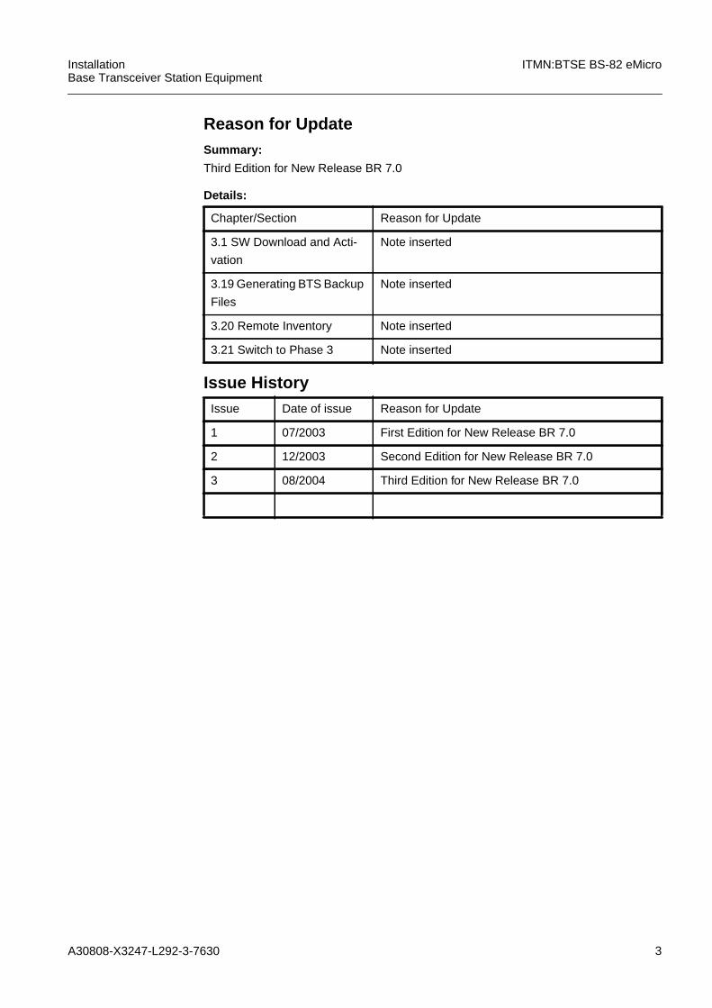
Reason for UpdateSummary:
Third Edition for New Release BR 7.0
Details:
Chapter/Section Reason for Update
3.1 SW Download and Acti-
vation
Note inserted
3.19 Generating BTS Backup
Files
Note inserted
3.20 Remote Inventory Note inserted
3.21 Switch to Phase 3 Note inserted
Issue HistoryIssue Date of issue Reason for Update
1 07/2003 First Edition for New Release BR 7.0
2 12/2003 Second Edition for New Release BR 7.0
3 08/2004 Third Edition for New Release BR 7.0
4 A30808-X3247-L292-3-7630
ITMN:BTSE BS-82 eMicro InstallationBase Transceiver Station Equipment
This document consists of a total of 110 pages. All pages are issue 3.
Contents
1 BS-82 Installation Test . . . . . . . . . . . . . . . . . . . . . . . . . . . . . . . . . . . . . . . . . . 91.1 Introduction . . . . . . . . . . . . . . . . . . . . . . . . . . . . . . . . . . . . . . . . . . . . . . . . . . 91.1.1 Aims of Installation and Commissioning . . . . . . . . . . . . . . . . . . . . . . . . . . . . 91.1.2 Used Symbols . . . . . . . . . . . . . . . . . . . . . . . . . . . . . . . . . . . . . . . . . . . . . . . 101.1.3 Optional Measurements . . . . . . . . . . . . . . . . . . . . . . . . . . . . . . . . . . . . . . . . 101.1.4 Using the ITMN . . . . . . . . . . . . . . . . . . . . . . . . . . . . . . . . . . . . . . . . . . . . . . 101.1.4.1 Required Knowledge . . . . . . . . . . . . . . . . . . . . . . . . . . . . . . . . . . . . . . . . . . 101.1.4.2 Test Equipment . . . . . . . . . . . . . . . . . . . . . . . . . . . . . . . . . . . . . . . . . . . . . . 111.1.4.3 Procedure in the Event of Faults After Commissioning . . . . . . . . . . . . . . . . 111.1.4.4 Procedure in the Event of Faults not Described in the UMN . . . . . . . . . . . . 111.1.4.5 Dealing with Defective Modules . . . . . . . . . . . . . . . . . . . . . . . . . . . . . . . . . . 111.1.4.6 Installation Test Sequence. . . . . . . . . . . . . . . . . . . . . . . . . . . . . . . . . . . . . . 121.1.5 Safety Instructions . . . . . . . . . . . . . . . . . . . . . . . . . . . . . . . . . . . . . . . . . . . . 131.1.5.1 Electrostatically Sensitive Components . . . . . . . . . . . . . . . . . . . . . . . . . . . . 131.1.5.2 System Voltages . . . . . . . . . . . . . . . . . . . . . . . . . . . . . . . . . . . . . . . . . . . . . 131.1.5.3 Changing Fuses. . . . . . . . . . . . . . . . . . . . . . . . . . . . . . . . . . . . . . . . . . . . . . 141.1.5.4 Grounding of Modules / Racks. . . . . . . . . . . . . . . . . . . . . . . . . . . . . . . . . . . 141.1.5.5 Handling Moist Module. . . . . . . . . . . . . . . . . . . . . . . . . . . . . . . . . . . . . . . . . 141.1.5.6 CE and UL Declaration of Conformity . . . . . . . . . . . . . . . . . . . . . . . . . . . . . 141.2 Visual Inspection of BTSE Mechanics . . . . . . . . . . . . . . . . . . . . . . . . . . . . . 141.2.1 STAR/LOOP/MULTIDROP . . . . . . . . . . . . . . . . . . . . . . . . . . . . . . . . . . . . . 151.2.2 Racks of BS-82 . . . . . . . . . . . . . . . . . . . . . . . . . . . . . . . . . . . . . . . . . . . . . . 161.2.3 Mounting and Installation of BTSE. . . . . . . . . . . . . . . . . . . . . . . . . . . . . . . . 171.2.3.1 Check of Base Transceiver Station BTSE . . . . . . . . . . . . . . . . . . . . . . . . . . 171.2.4 Antenna and Feeder Cable . . . . . . . . . . . . . . . . . . . . . . . . . . . . . . . . . . . . . 171.2.5 Module HW Coding . . . . . . . . . . . . . . . . . . . . . . . . . . . . . . . . . . . . . . . . . . . 171.3 Visual Inspection of BTSE Electrics . . . . . . . . . . . . . . . . . . . . . . . . . . . . . . . 171.3.1 Polarity of DC Input and Tolerance (DCPSC) . . . . . . . . . . . . . . . . . . . . . . . 171.3.2 AC Input and Tolerance (ACPSC) . . . . . . . . . . . . . . . . . . . . . . . . . . . . . . . . 181.3.3 Fuses . . . . . . . . . . . . . . . . . . . . . . . . . . . . . . . . . . . . . . . . . . . . . . . . . . . . . . 181.3.4 Temperature Sensor . . . . . . . . . . . . . . . . . . . . . . . . . . . . . . . . . . . . . . . . . . 181.3.5 Operator Alarms. . . . . . . . . . . . . . . . . . . . . . . . . . . . . . . . . . . . . . . . . . . . . . 191.4 Visual Inspection of BTSE Modules . . . . . . . . . . . . . . . . . . . . . . . . . . . . . . . 201.4.1 Module Identification . . . . . . . . . . . . . . . . . . . . . . . . . . . . . . . . . . . . . . . . . . 201.4.2 BTSE Modules . . . . . . . . . . . . . . . . . . . . . . . . . . . . . . . . . . . . . . . . . . . . . . . 201.4.3 Modules in the Racks. . . . . . . . . . . . . . . . . . . . . . . . . . . . . . . . . . . . . . . . . . 211.4.4 Numbering of Modules and Hardware Managed Objects . . . . . . . . . . . . . . 211.4.5 Attribute Settings for DILNA. . . . . . . . . . . . . . . . . . . . . . . . . . . . . . . . . . . . . 231.4.6 Antenna Connection. . . . . . . . . . . . . . . . . . . . . . . . . . . . . . . . . . . . . . . . . . . 231.4.7 RF System Cabling . . . . . . . . . . . . . . . . . . . . . . . . . . . . . . . . . . . . . . . . . . . 231.4.8 Antenna Combining . . . . . . . . . . . . . . . . . . . . . . . . . . . . . . . . . . . . . . . . . . . 261.4.8.1 Combining on Air . . . . . . . . . . . . . . . . . . . . . . . . . . . . . . . . . . . . . . . . . . . . . 261.4.8.2 Hybrid Combining. . . . . . . . . . . . . . . . . . . . . . . . . . . . . . . . . . . . . . . . . . . . . 261.4.9 Adjustable Devices on Modules . . . . . . . . . . . . . . . . . . . . . . . . . . . . . . . . . . 27
A30808-X3247-L292-3-7630 5
InstallationBase Transceiver Station Equipment
ITMN:BTSE BS-82 eMicro
1.4.9.1 Switch Setting on COBAM . . . . . . . . . . . . . . . . . . . . . . . . . . . . . . . . . . . . . 271.4.9.2 Switch Setting on A:DUAMCOM. . . . . . . . . . . . . . . . . . . . . . . . . . . . . . . . . 271.4.9.3 Switch Setting on CORE Backplane . . . . . . . . . . . . . . . . . . . . . . . . . . . . . . 271.4.10 Software . . . . . . . . . . . . . . . . . . . . . . . . . . . . . . . . . . . . . . . . . . . . . . . . . . . 291.4.10.1 Boot Software (FW) . . . . . . . . . . . . . . . . . . . . . . . . . . . . . . . . . . . . . . . . . . 291.4.10.2 Software Images SWI . . . . . . . . . . . . . . . . . . . . . . . . . . . . . . . . . . . . . . . . . 291.5 Preparation for Offline Tests . . . . . . . . . . . . . . . . . . . . . . . . . . . . . . . . . . . . 301.5.1 Recommended Test Equipment and Tools. . . . . . . . . . . . . . . . . . . . . . . . . 311.5.1.1 Test Equipment. . . . . . . . . . . . . . . . . . . . . . . . . . . . . . . . . . . . . . . . . . . . . . 311.5.1.2 Tools . . . . . . . . . . . . . . . . . . . . . . . . . . . . . . . . . . . . . . . . . . . . . . . . . . . . . . 321.5.2 Preparation and Presetting of Test Equipment . . . . . . . . . . . . . . . . . . . . . . 321.5.2.1 Test Equipment. . . . . . . . . . . . . . . . . . . . . . . . . . . . . . . . . . . . . . . . . . . . . . 321.5.2.2 Software (SW). . . . . . . . . . . . . . . . . . . . . . . . . . . . . . . . . . . . . . . . . . . . . . . 331.5.2.3 Boot Software/Firmware (SW/FW) . . . . . . . . . . . . . . . . . . . . . . . . . . . . . . . 331.5.3 BTSE Power ON . . . . . . . . . . . . . . . . . . . . . . . . . . . . . . . . . . . . . . . . . . . . . 331.5.3.1 Fuses . . . . . . . . . . . . . . . . . . . . . . . . . . . . . . . . . . . . . . . . . . . . . . . . . . . . . 331.5.3.2 LED Indication. . . . . . . . . . . . . . . . . . . . . . . . . . . . . . . . . . . . . . . . . . . . . . . 33
2 Tasklist . . . . . . . . . . . . . . . . . . . . . . . . . . . . . . . . . . . . . . . . . . . . . . . . . . . . 35
3 Procedures . . . . . . . . . . . . . . . . . . . . . . . . . . . . . . . . . . . . . . . . . . . . . . . . . 373.1 SW Download and Activation . . . . . . . . . . . . . . . . . . . . . . . . . . . . . . . . . . . 383.2 Hardware Related Managed Objects . . . . . . . . . . . . . . . . . . . . . . . . . . . . . 433.3 Rack . . . . . . . . . . . . . . . . . . . . . . . . . . . . . . . . . . . . . . . . . . . . . . . . . . . . . . 443.4 ACDCP . . . . . . . . . . . . . . . . . . . . . . . . . . . . . . . . . . . . . . . . . . . . . . . . . . . . 463.5 ACT. . . . . . . . . . . . . . . . . . . . . . . . . . . . . . . . . . . . . . . . . . . . . . . . . . . . . . . 483.6 BATTERY . . . . . . . . . . . . . . . . . . . . . . . . . . . . . . . . . . . . . . . . . . . . . . . . . . 503.7 COBA . . . . . . . . . . . . . . . . . . . . . . . . . . . . . . . . . . . . . . . . . . . . . . . . . . . . . 523.8 DCU . . . . . . . . . . . . . . . . . . . . . . . . . . . . . . . . . . . . . . . . . . . . . . . . . . . . . . 543.9 A:DUAMCO. . . . . . . . . . . . . . . . . . . . . . . . . . . . . . . . . . . . . . . . . . . . . . . . . 593.10 FANP . . . . . . . . . . . . . . . . . . . . . . . . . . . . . . . . . . . . . . . . . . . . . . . . . . . . . 633.11 Create the Alarm Configuration (ENVABTSE) . . . . . . . . . . . . . . . . . . . . . . 643.12 Setting the BTSE Attributes . . . . . . . . . . . . . . . . . . . . . . . . . . . . . . . . . . . . 663.13 BPORT . . . . . . . . . . . . . . . . . . . . . . . . . . . . . . . . . . . . . . . . . . . . . . . . . . . . 693.14 SET BTSM . . . . . . . . . . . . . . . . . . . . . . . . . . . . . . . . . . . . . . . . . . . . . . . . . 713.15 LAPDLE . . . . . . . . . . . . . . . . . . . . . . . . . . . . . . . . . . . . . . . . . . . . . . . . . . . 733.16 Check the State of All Modules. . . . . . . . . . . . . . . . . . . . . . . . . . . . . . . . . . 753.17 Replacing of Failed HW . . . . . . . . . . . . . . . . . . . . . . . . . . . . . . . . . . . . . . . 763.18 External Alarm Check . . . . . . . . . . . . . . . . . . . . . . . . . . . . . . . . . . . . . . . . . 773.19 Generating BTS Backup Files. . . . . . . . . . . . . . . . . . . . . . . . . . . . . . . . . . . 783.20 Remote Inventory . . . . . . . . . . . . . . . . . . . . . . . . . . . . . . . . . . . . . . . . . . . . 803.21 Switch to Phase 3 . . . . . . . . . . . . . . . . . . . . . . . . . . . . . . . . . . . . . . . . . . . . 893.22 Setup for Optional RF-Tests . . . . . . . . . . . . . . . . . . . . . . . . . . . . . . . . . . . . 913.22.1 Measuring Set-up . . . . . . . . . . . . . . . . . . . . . . . . . . . . . . . . . . . . . . . . . . . . 913.23 Spectrum Analyzer Measurements. . . . . . . . . . . . . . . . . . . . . . . . . . . . . . . 933.24 VSWR Test . . . . . . . . . . . . . . . . . . . . . . . . . . . . . . . . . . . . . . . . . . . . . . . . . 963.25 RFA-Confirmation: Unit ATMN . . . . . . . . . . . . . . . . . . . . . . . . . . . . . . . . . . 96

6 A30808-X3247-L292-3-7630
ITMN:BTSE BS-82 eMicro InstallationBase Transceiver Station Equipment
4 Tables, lists and figures (TAB) . . . . . . . . . . . . . . . . . . . . . . . . . . . . . . . . . . . 97TABIN
4.1 Frequency/Channel Conversion Table. . . . . . . . . . . . . . . . . . . . . . . . . . . . . 98
5 Appendix . . . . . . . . . . . . . . . . . . . . . . . . . . . . . . . . . . . . . . . . . . . . . . . . . . . 995.1 Examples of Configuration . . . . . . . . . . . . . . . . . . . . . . . . . . . . . . . . . . . . . . 995.1.1 Types of DCU. . . . . . . . . . . . . . . . . . . . . . . . . . . . . . . . . . . . . . . . . . . . . . . . 995.1.1.1 DCUDUXx . . . . . . . . . . . . . . . . . . . . . . . . . . . . . . . . . . . . . . . . . . . . . . . . . . 995.1.1.2 DCURG . . . . . . . . . . . . . . . . . . . . . . . . . . . . . . . . . . . . . . . . . . . . . . . . . . . . 995.1.1.3 DCULGx. . . . . . . . . . . . . . . . . . . . . . . . . . . . . . . . . . . . . . . . . . . . . . . . . . . 1005.1.2 Combining on air with DCUDUX . . . . . . . . . . . . . . . . . . . . . . . . . . . . . . . . 1015.1.3 Hybrid Combining. . . . . . . . . . . . . . . . . . . . . . . . . . . . . . . . . . . . . . . . . . . . 1025.1.3.1 Types of A:DUAMCOM . . . . . . . . . . . . . . . . . . . . . . . . . . . . . . . . . . . . . . . 1025.1.3.2 A:DUAMCOM configurations . . . . . . . . . . . . . . . . . . . . . . . . . . . . . . . . . . . 1035.1.4 How to Configure an Additional A:DUAMCO . . . . . . . . . . . . . . . . . . . . . . . 1045.1.5 Change of Combiner Configuration . . . . . . . . . . . . . . . . . . . . . . . . . . . . . . 1055.2 Binary-HEX-Decimal Table . . . . . . . . . . . . . . . . . . . . . . . . . . . . . . . . . . . . 1065.3 Power/Level Conversion . . . . . . . . . . . . . . . . . . . . . . . . . . . . . . . . . . . . . . 1065.4 Used Expressions . . . . . . . . . . . . . . . . . . . . . . . . . . . . . . . . . . . . . . . . . . . 1075.5 Module Identification by Inventory Data and Label . . . . . . . . . . . . . . . . . . 108
6 Abbreviations . . . . . . . . . . . . . . . . . . . . . . . . . . . . . . . . . . . . . . . . . . . . . . . 109
A30808-X3247-L292-3-7630 7
InstallationBase Transceiver Station Equipment
ITMN:BTSE BS-82 eMicro
IllustrationsFig. 1.1 Used Symbols . . . . . . . . . . . . . . . . . . . . . . . . . . . . . . . . . . . . . . . . . . . . 10
Fig. 1.2 Installation Test Sequence (without Network Integration) . . . . . . . . . . . 12
Fig. 1.3 ESD Symbol. . . . . . . . . . . . . . . . . . . . . . . . . . . . . . . . . . . . . . . . . . . . . . 13
Fig. 1.4 CE Symbol / UL Symbol . . . . . . . . . . . . . . . . . . . . . . . . . . . . . . . . . . . . 14
Fig. 1.5 Star/Loop/Multidrop . . . . . . . . . . . . . . . . . . . . . . . . . . . . . . . . . . . . . . . . 15
Fig. 1.6 Example for eMicroBTS. . . . . . . . . . . . . . . . . . . . . . . . . . . . . . . . . . . . . 16
Fig. 1.7 AC breakers . . . . . . . . . . . . . . . . . . . . . . . . . . . . . . . . . . . . . . . . . . . . . . 18
Fig. 1.8 Numbering of modules and HMOs with A:DUAMCO 2M (for example). 22
Fig. 1.9 RF System cabling DCULG-A:DUAMCO4M . . . . . . . . . . . . . . . . . . . . . 25
Fig. 1.10 RF System cabling DCUDUX . . . . . . . . . . . . . . . . . . . . . . . . . . . . . . . . 26
Fig. 1.11 Can-bus . . . . . . . . . . . . . . . . . . . . . . . . . . . . . . . . . . . . . . . . . . . . . . . . . 28
Fig. 1.12 Can Bus Termination . . . . . . . . . . . . . . . . . . . . . . . . . . . . . . . . . . . . . . . 29
Fig. 3.1 Measurement setup . . . . . . . . . . . . . . . . . . . . . . . . . . . . . . . . . . . . . . . . 91
Fig. 3.2 Example 1: Test Adapter TAD-L (S30861-U2003-X-1) and ExtensionAdapter TADADPT (S30861-U2170-x) . . . . . . . . . . . . . . . . . . . . . . . . . 92
Fig. 3.3 Example 2: Test Adapter TADlight (S30861-U688-X) with Integrated Ex-tension Adapter TADADPT (S30861-U2170-x) for COBAM . . . . . . . . . 92
Fig. 3.4 Spectrum analyzer HP8954A. . . . . . . . . . . . . . . . . . . . . . . . . . . . . . . . . 93
Fig. 5.1 DCUDUXx (x = frequency denotation). . . . . . . . . . . . . . . . . . . . . . . . . . 99
Fig. 5.2 DCURG . . . . . . . . . . . . . . . . . . . . . . . . . . . . . . . . . . . . . . . . . . . . . . . . 100
Fig. 5.3 DCULGx. . . . . . . . . . . . . . . . . . . . . . . . . . . . . . . . . . . . . . . . . . . . . . . . 101
Fig. 5.4 Combining on air with full diversity. . . . . . . . . . . . . . . . . . . . . . . . . . . . 102
Fig. 5.5 A:DUAMCO2M. . . . . . . . . . . . . . . . . . . . . . . . . . . . . . . . . . . . . . . . . . . 102
Fig. 5.6 A:DUAMCO4M. . . . . . . . . . . . . . . . . . . . . . . . . . . . . . . . . . . . . . . . . . . 102
Fig. 5.7 A:DUAMCO 2M serving 2 cells with full diversity. . . . . . . . . . . . . . . . . 103
Fig. 5.8 A:DUAMCO 4M serving 1 cell without diversity . . . . . . . . . . . . . . . . . . 104
Fig. 5.9 Labels and Inventory Data . . . . . . . . . . . . . . . . . . . . . . . . . . . . . . . . . . 108

8 A30808-X3247-L292-3-7630
ITMN:BTSE BS-82 eMicro InstallationBase Transceiver Station Equipment
TablesTab. 1.1 Module HW Code Key . . . . . . . . . . . . . . . . . . . . . . . . . . . . . . . . . . . . . . 17
Tab. 1.2 ACPSC/DCPSC or ACPSC/U alarm ports . . . . . . . . . . . . . . . . . . . . . . . 19
Tab. 1.3 Attribute settings for DCUDUX . . . . . . . . . . . . . . . . . . . . . . . . . . . . . . . . 23
Tab. 1.4 Attribute settings for DCULG . . . . . . . . . . . . . . . . . . . . . . . . . . . . . . . . . 23
Tab. 1.5 RF Cabling . . . . . . . . . . . . . . . . . . . . . . . . . . . . . . . . . . . . . . . . . . . . . . . 24
Tab. 1.6 Adjustable Devices . . . . . . . . . . . . . . . . . . . . . . . . . . . . . . . . . . . . . . . . . 27
Tab. 1.7 Boot Software . . . . . . . . . . . . . . . . . . . . . . . . . . . . . . . . . . . . . . . . . . . . . 29
Tab. 1.8 Software Images SWI . . . . . . . . . . . . . . . . . . . . . . . . . . . . . . . . . . . . . . . 29
Tab. 5.1 Additional A:DUAMCO 4:1 in Rack 0 . . . . . . . . . . . . . . . . . . . . . . . . . . 104
Tab. 5.2 Additional A:DUAMCOs 2:1 . . . . . . . . . . . . . . . . . . . . . . . . . . . . . . . . . 105
Tab. 5.3 Binary-HEX-Decimal Table . . . . . . . . . . . . . . . . . . . . . . . . . . . . . . . . . . 106
Tab. 5.4 Power conversion table. . . . . . . . . . . . . . . . . . . . . . . . . . . . . . . . . . . . . 106
A30808-X3247-L292-3-7630 9
InstallationBase Transceiver Station Equipment
ITMN:BTSE BS-82 eMicro
1 BS-82 Installation Test
1.1 Introduction
1.1.1 Aims of Installation and Commissioning
Installation and commissioning is based on extensive, high quality final factory tests. Inthe factory, each module is tested during its production process; all RF parameters suchas the power and modulation spectrum are measured in the complete BTSE rack incustomer configuration.
The Final Factory Tests comply with the tests and measurements required by GSMspecifications.
The installation test can therefore concentrate on functional tests of the delivered HW.
The installation and commissioning of a network element followed by unit acceptance isproof of:
It is assumed that the subdivision of tests in:
– final factory tests
– installation/commissioning (HW-test, SW-test)
– network integration (data base tests)
allows a quick, economical, and reliable commissioning procedure.
– a correct and complete delivery according to the network planning and thecustomer order.
– a correct mechanical and electrical installation according to the installationdocuments.
– the functional ability of the supplied HW(correct functioning of the NEs at an interface in relation to other networkelements).

10 A30808-X3247-L292-3-7630
ITMN:BTSE BS-82 eMicro InstallationBase Transceiver Station Equipment
1.1.2 Used Symbols
The following symbols are used in this manual:
Fig. 1.1 Used Symbols
1.1.3 Optional Measurements
RF- (Radio Frequency) measurements, which can be performed by means of spectrumanalysers or other BS-testers, are optional possibilities that can be done for localizationof suspected faults.They need not to be done in every BTSE as regular measurements.
1.1.4 Using the ITMN
1.1.4.1 Required KnowledgeOnly trained personnel should carry out the installation and installation tests.The SIEMENS training centre offers the necessary courses.
Reference to another procedure step
Symbol Meaning
ESD (Electrostatically Sensitive Devices) precautions to be taken
Note; important information
Warning; the notes given here are to be followed with care.
b
h
Use LMT to enter commands
Reference to another chapter
Reference to another procedure. Return after finishing.i
i
!Non-observance can lead to personal injury or property damage.

A30808-X3247-L292-3-7630 11
InstallationBase Transceiver Station Equipment
ITMN:BTSE BS-82 eMicro
1.1.4.2 Test EquipmentThe test equipment and tools required for the tests are described in the correspondingchapters.
1.1.4.3 Procedure in the Event of Faults After CommissioningIf faults occur in on-line operation they should be localized and cleared in accordancewith the instructions in the Maintenance Manual (MMN).
1.1.4.4 Procedure in the Event of Faults not Described in the UMNFirst the specialist in the installation team should try to clear the fault. To eliminate seri-ous faults, a fault report must be filled out, providing the following information in detail:
– description of the test step attempted
– description of the system response
– description of any system activities taking place at the same time, e.g. work done byother testers during modifications to hardware or software
In the case of an software error a fault report must always be written.
1.1.4.5 Dealing with Defective ModulesIf a module proves to be defective, it should be sent in an appropriate packaging to therepair centre with the following information:
– Name and code of the site
– Name and code number of the module
– Description of the fault

12 A30808-X3247-L292-3-7630
ITMN:BTSE BS-82 eMicro InstallationBase Transceiver Station Equipment
1.1.4.6 Installation Test Sequence
Fig. 1.2 Installation Test Sequence (without Network Integration)
Visual Checkof BTS-Mechanics
Visual Checkof BTS-Electric
Visual Checkof Boards
Preparation forFunction Tests
S T A R T
E N D
VISUALCHECK
OFFLINE
CommissioningSequence
A30808-X3247-L292-3-7630 13
InstallationBase Transceiver Station Equipment
ITMN:BTSE BS-82 eMicro
1.1.5 Safety Instructions
1.1.5.1 Electrostatically Sensitive Components
General
All modules are to be handled with extreme care as each one may contain electrostati-cally sensitive devices (ESD).
All modules which contain ESD are marked with the ESD symbol.
Fig. 1.3 ESD Symbol
Rules for Handling
The following safety instructions are to be noticed:
– Personnel should avoid wearing synthetic clothing and shoes with plastic soles, asthese encourage the build-up of electrostatic charge.
– Before handling modules, personnel have to be discharged of electrostatic charging.For this reason personnel always have to put on a grounded wrist strap beforechanging a module.
– ESDs must not be brought in contact with electrostatically charged or chargeableobjects.
– ESDs has to come in contact with high valued discharging material ("gentle" dis-charching) only, i.e. should not be made subject to "harsh" discharging with, for ex-ample, a metal plate.
– ESDs should be set down on grounded surfaces only (flexible bases with a ground-ing connection for servicing purposes)
– ESDs should not be brought into the vicinity of strong DC electrical fields, e.g. cath-ode ray tubes/monitors (safety distance at least 10 cm or 4”).
– All tools and test equipment have to be discharged of electrostatic charging beforehandling modules.
– ESDs has to be transported in appropriate packing only. A grounded wrist strap mustbe put on before removing ESDs.
– Modules should only be touched by their edges. Components or printed circuitsshould not be touched.
1.1.5.2 System VoltagesThe following types of power supply are available:
– 115 V AC (ACPSC/U)
– 230 V AC (ACPSC) or
– -48 V DC (DCPSC)
14 A30808-X3247-L292-3-7630
ITMN:BTSE BS-82 eMicro InstallationBase Transceiver Station Equipment
Some parts are supplied with the line voltage directly and are to be handled with safetytools with extreme care.Only trained personnel should carry out those jobs.Care must be taken because some parts produce a high operating temperature.
This warning must appear in the original German text:
Alle Systemeinheiten benötigen eine Wechselspannung von 230V (bzw. 115V oder -48V DC), die in eine Gleichspannung von -48V (positiver Pol an Masse) umgesetzt wird.Einige Teile führen Netzspannung und sind mit besonderer Sorgfalt zu behandeln. Nurausgebildetes Personal darf entsprechende Arbeiten übernehmen.Weiterhin ist zu beachten, daß sich einige Bauteile stark erhitzen.
1.1.5.3 Changing FusesFuses may only be changed by qualified service personal. Only authorized fuses as giv-en in the manual may be used. Fuses are to be changed as described in this manual.
1.1.5.4 Grounding of Modules / RacksAll modules must be plugged in correctly to ground them before power is switched on.Ground connections between racks must be plugged in correctly.
1.1.5.5 Handling Moist ModuleAfter storage in a humid environment, modules with condensation moisture must bedried before they are used. Otherwise the modules may be damaged or destroyed.
1.1.5.6 CE and UL Declaration of Conformity
Fig. 1.4 CE Symbol / UL Symbol
The CE and UL declaration of conformity for the product will be fulfilled if the setup andcabling is carried out in accordance with the specification in the manual and the docu-mentation listed there, such as mounting instructions, cable lists etc. Where necessary,account should be taken of project-specific documentation.
Deviations from the specifications or arbitrary changes during setup, such as the use ofcable types with lower screening values, for example, can lead to the CE requirementsbeing violated. In such cases the CE declaration of conformity is invalidated and the re-sponsibility passes to the person who has caused the deviations.
1.2 Visual Inspection of BTSE Mechanics
A visual inspection for all delivered racks has to be executed to make sure that theseracks are not damaged and the quantity and location of the modules is correct.
A30808-X3247-L292-3-7630 15
InstallationBase Transceiver Station Equipment
ITMN:BTSE BS-82 eMicro
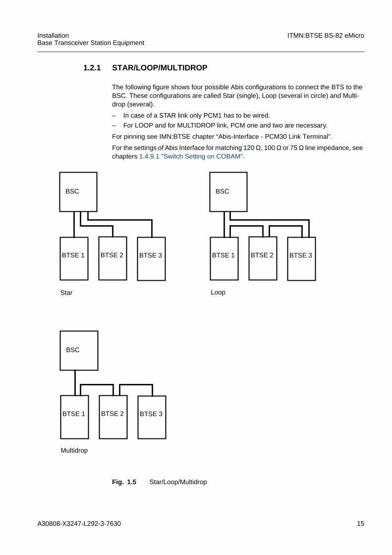
1.2.1 STAR/LOOP/MULTIDROP
The following figure shows four possible Abis configurations to connect the BTS to theBSC. These configurations are called Star (single), Loop (several in circle) and Multi-drop (several).
– In case of a STAR link only PCM1 has to be wired.
– For LOOP and for MULTIDROP link, PCM one and two are necessary.
For pinning see IMN:BTSE chapter “Abis-Interface - PCM30 Link Terminal”.
For the settings of Abis Interface for matching 120 Ω, 100 Ω or 75 Ω line impedance, seechapters 1.4.9.1 "Switch Setting on COBAM".
Fig. 1.5 Star/Loop/Multidrop
Multidrop
BSC
BTSE 2BTSE 1 BTSE 3
BSC
BTSE 2BTSE 1 BTSE 3
BSC
BTSE 2BTSE 1 BTSE 3
Star Loop

16 A30808-X3247-L292-3-7630
ITMN:BTSE BS-82 eMicro InstallationBase Transceiver Station Equipment
1.2.2 Racks of BS-82
A BS-82 can consist of one Master Cabinet and one Extension Cabinet (optional). Thenumbering of the Racks is shown in the table below.
Fig. 1.6 shows a BS-82 with Master Cabinet and Extension Cabinet. On the top of theCabinets add-on modules (up to seven, alternative 35 kg or 77 pounds) can be installed.
Fig. 1.6 Example for eMicroBTS
Rack numbering Type of Rack
0 Master Cabinet 1 Extension Cabinet
Extension Cabinet
FANM
air guide
DC
U1
DC
U0
air guide
INT
EN
NA
HEATERM
mou
ntin
g pl
ate
OV
PT
MO
VP
T-
AC
PS
C/
DC
PS
CA
CP
SC
/U
air
bypa
ss
BA
TT
ER
YM
CP
:BA
T-
TE
RY
M
connection panel
M:C
OB
AM
CP
:TIF
Add-On Module 0
Add-On Module 1
FANM
Add-On Module 2
air guideD
CU
1
DC
U0
air guide
INT
EN
NA
HEATERM
mou
ntin
g pl
ate
CP
:OV
PT
M
AC
PS
C/
DC
PS
CA
CP
SC
/U
air
bypa
ss
BA
TT
ER
YM
CP
:BA
T-
TE
RY
M
connection panel
CP
:CO
BA
MC
P:T
IF
FANM
Master Cabinet
A30808-X3247-L292-3-7630 17
InstallationBase Transceiver Station Equipment
ITMN:BTSE BS-82 eMicro
1.2.3 Mounting and Installation of BTSE
Check the internal/external interfaces and least replaceable units (LRU). For more de-tailed information refer to the HW:BTSE Modules.
1.2.3.1 Check of Base Transceiver Station BTSECheck for delivery quality and quantity on site:
– installation of BTS rack (rack fixing, fixed boards)
– damage to rack or shelter (paintwork, dents)
– correct insertion of modules
– checkout CE-lable
– system/rack cabling (fixed RF-Connectors!)
– grounding, earthing
– main fuses
– external interfaces: power supply, antenna and Abis wiring
1.2.4 Antenna and Feeder Cable
The types of antennas and feeder cables have to be tested in advance!
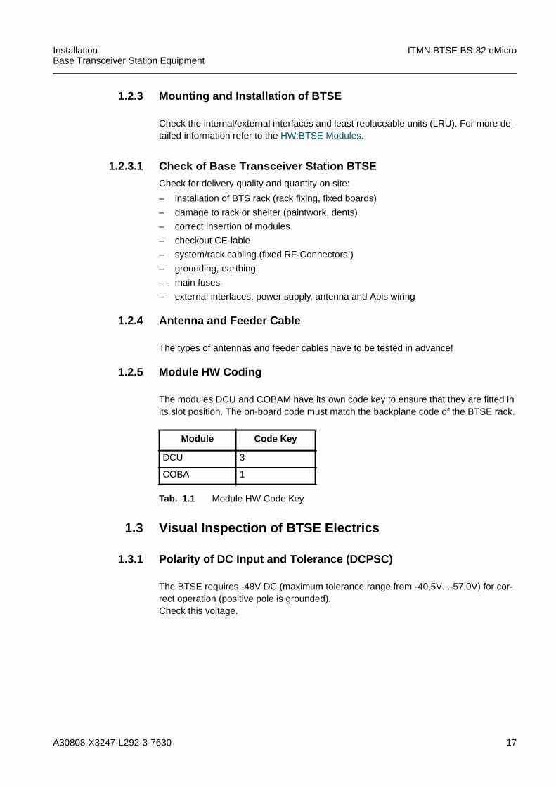
1.2.5 Module HW Coding
The modules DCU and COBAM have its own code key to ensure that they are fitted inits slot position. The on-board code must match the backplane code of the BTSE rack.
1.3 Visual Inspection of BTSE Electrics
1.3.1 Polarity of DC Input and Tolerance (DCPSC)
The BTSE requires -48V DC (maximum tolerance range from -40,5V...-57,0V) for cor-rect operation (positive pole is grounded).Check this voltage.
Module Code Key
DCU 3
COBA 1
Tab. 1.1 Module HW Code Key

18 A30808-X3247-L292-3-7630
ITMN:BTSE BS-82 eMicro InstallationBase Transceiver Station Equipment
1.3.2 AC Input and Tolerance (ACPSC)
The BTSE requires 115 V +/- 15%, or 220/230 V +/- 10% for correct operation (positivepole is grounded).Check this voltage.
1.3.3 Fuses
The AC breakers are mounted at the frontside of the rack on the module ACPSC. TheDC breakers are mounted at the frontside of the rack on the module DCPSC.Check for fully equipped fuses and that all fuses are being switched on.
Fig. 1.7 AC breakers
1.3.4 Temperature Sensor
The eMicro has got a temperature sensor to control proper operation between -45˚C and+55˚C (-49˚F and 131˚F).The temperature sensor is located under the FAN at the top of the cabinet and is con-nected with ACPSC/ACPSC/U or DCPSC. The temperature sensor has to be checkedfor correct installation and functionality.
iApply ACPSC (ACPSC/U) or DCPSC for the test either.

A30808-X3247-L292-3-7630 19
InstallationBase Transceiver Station Equipment
ITMN:BTSE BS-82 eMicro
1.3.5 Operator Alarms
The BS-82 eMicro supports in each cabinet 16 ENVA (ENVA0... ENVA15) alarms thatare defined by the operator, for the creation see chapter 1 "ENVABTSE creation". Thealarms ENVA0 to ENVA6 are used for internal wired alarms. Only the first 16 ENVAscan have to be configured by the operator!
Alarms can be communicated on different ways:
– via CC-link,
– via the alarm ports of ACPSC/DCPSC,
– via CAN bus.
The basic philosophy of the alarm handling in the eMicro can be described as follows:
– alarms of the DCU units are transferred on the CC-link via M:SIPRO with exceptionof the M:AMCO2 alarms (often called LNA alarms). The M:AMCO2LG version(DCULG) does not need any alarm handling.
– alarms of other modules are transferred via CAN bus if available,
– all other alarms are connected by ACPSC/DCPSC or ACPSC/U and communicatedvia CAN bus.
M:COBAM alarm ports will not be used.
There are connectors for 16 BTS internal alarms and for 16 external alarms handled bythe controller board (located on ACPSC/DCPSC or ACPSC/U module). All alarms inputshave got pull up resistors to logical high.
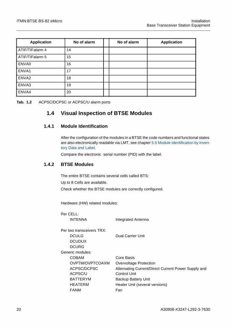
The table overviews the use of the ACPSC/DCPSC or ACPSC/U alarm ports.
Application No of alarm No of alarm Application
RDO 0 21 ENVA5
FAN0 1 22 ENVA6
FAN1 2 23 ENVA7
FAN2 3 24 ENVA8
FAN3 4 25 ENVA9
n.c. 5 26 ENVA10
AMCO Alarm 0 6 27 ENVA11
AMCO Alarm 1 7 28 ENVA12
AMCO Alarm 2 8 29 ENVA13
AMCO Alarm 3 9 30 ENVA14
ATIF/TIFalarm 0 10 31 ENVA15
ATIF/TIFalarm 1 11
ATIF/TIFalarm 2 12
ATIF/TIFalarm 3 13
Tab. 1.2 ACPSC/DCPSC or ACPSC/U alarm ports
20 A30808-X3247-L292-3-7630
ITMN:BTSE BS-82 eMicro InstallationBase Transceiver Station Equipment
1.4 Visual Inspection of BTSE Modules
1.4.1 Module Identification
After the configuration of the modules in a BTSE the code numbers and functional statesare also electronically readable via LMT, see chapter 5.5 Module Identification by Inven-tory Data and Label.
Compare the electronic serial number (PID) with the label.
1.4.2 BTSE Modules
The entire BTSE contains several cells called BTS:
Up to 8 Cells are available.
Check whether the BTSE modules are correctly configured.
ATIF/TIFalarm 4 14
ATIF/TIFalarm 5 15
ENVA0 16
ENVA1 17
ENVA2 18
ENVA3 19
ENVA4 20
Application No of alarm No of alarm Application
Tab. 1.2 ACPSC/DCPSC or ACPSC/U alarm ports
Hardware (HW) related modules:
Per CELL:INTENNA Integrated Antenna
Per two transceivers TRX:DCULG Dual Carrier UnitDCUDUXDCURG
Generic modules:COBAM Core BasisOVPTM/OVPTCOAXM Overvoltage ProtectionACPSC/DCPSCACPSC/U
Alternating Current/Direct Current Power Supply andControl Unit
BATTERYM Backup Battery UnitHEATERM Heater Unit (several versions)FANM Fan
A30808-X3247-L292-3-7630 21
InstallationBase Transceiver Station Equipment
ITMN:BTSE BS-82 eMicro
Redundancy
No redundancy supported
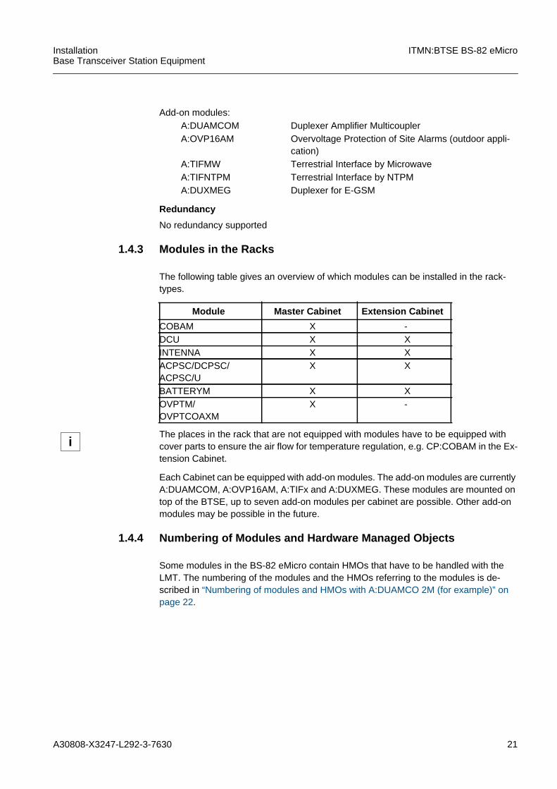
1.4.3 Modules in the Racks
The following table gives an overview of which modules can be installed in the rack-types.
Each Cabinet can be equipped with add-on modules. The add-on modules are currentlyA:DUAMCOM, A:OVP16AM, A:TIFx and A:DUXMEG. These modules are mounted ontop of the BTSE, up to seven add-on modules per cabinet are possible. Other add-onmodules may be possible in the future.
1.4.4 Numbering of Modules and Hardware Managed Objects
Some modules in the BS-82 eMicro contain HMOs that have to be handled with theLMT. The numbering of the modules and the HMOs referring to the modules is de-scribed in “Numbering of modules and HMOs with A:DUAMCO 2M (for example)” onpage 22.
Add-on modules:A:DUAMCOM Duplexer Amplifier MulticouplerA:OVP16AM Overvoltage Protection of Site Alarms (outdoor appli-
cation)A:TIFMW Terrestrial Interface by MicrowaveA:TIFNTPM Terrestrial Interface by NTPMA:DUXMEG Duplexer for E-GSM
Module Master Cabinet Extension Cabinet
COBAM X -DCU X XINTENNA X XACPSC/DCPSC/ACPSC/U
X X
BATTERYM X XOVPTM/OVPTCOAXM
X -
iThe places in the rack that are not equipped with modules have to be equipped withcover parts to ensure the air flow for temperature regulation, e.g. CP:COBAM in the Ex-tension Cabinet.

22 A30808-X3247-L292-3-7630
ITMN:BTSE BS-82 eMicro InstallationBase Transceiver Station Equipment
Fig. 1.8 Numbering of modules and HMOs with A:DUAMCO 2M (for example)
The HMOs ACT and ACDCP are located on the module ACPSC/DCPSC and ACP-SC/U.Each module DCU contains two HMOs CU and two HMOs DILNA. Each DCU containstwo LNAs, that are managed with the HMO DILNA.The attribute settings for DILNA are described in the table below.
DCU 0
CU 0
CU 1
DILNA 0
DILNA 1
DCU 1
CU 2
CU 3
DILNA 2
DILNA 3
CO
BA
0
BATTERY 0ACPSC/ACPC/UDCPSC 0
FANM 0
A:DUAMCO 0
DULNA 0
DUVSWR 0
DCU 0
CU 0
CU 1
DILNA 0
DILNA 1
DCU 1
CU 2
CU 3
DILNA 2
DILNA 3
CP
:CO
BA
FANM 0
A:DUAMCO 0
DULNA 0
DUVSWR 0
Master Cabinet (Rack 0) Extension Cabinet (Rack 1)
A:DUAMCO 1
DULNA 1
DUVSWR 1
ACT ACDCP
A:DUAMCO 1
DULNA 1
DUVSWR 1
BATTERY 0ACPSC/ACPC/UDCPSC 0
ACT ACDCP
A30808-X3247-L292-3-7630 23
InstallationBase Transceiver Station Equipment
ITMN:BTSE BS-82 eMicro
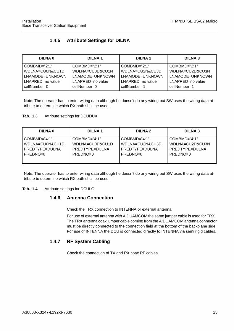
1.4.5 Attribute Settings for DILNA
1.4.6 Antenna Connection
Check the TRX connection to INTENNA or external antenna.
For use of external antenna with A:DUAMCOM the same jumper cable is used for TRX.The TRX antenna coax jumper cable coming from the A:DUAMCOM antenna connectormust be directly connected to the connection field at the bottom of the backplane side.For use of INTENNA the DCU is connected directly to INTENNA via semi rigid cables.
1.4.7 RF System Cabling
Check the connection of TX and RX coax RF cables.
DILNA 0 DILNA 1 DILNA 2 DILNA 3
COMBMD="2:1"WDLNA=CU0N&CU1DLNAMODE=UNKNOWNLNAPRED=no valuecellNumber=0
COMBMD="2:1"WDLNA=CU0D&CU1NLNAMODE=UNKNOWNLNAPRED=no valuecellNumber=0
COMBMD="2:1"WDLNA=CU2N&CU3DLNAMODE=UNKNOWNLNAPRED=no valuecellNumber=1
COMBMD="2:1"WDLNA=CU2D&CU3NLNAMODE=UNKNOWNLNAPRED=no valuecellNumber=1
Note: The operator has to enter wiring data although he doesn’t do any wiring but SW uses the wiring data at-tribute to determine which RX path shall be used.
Tab. 1.3 Attribute settings for DCUDUX
DILNA 0 DILNA 1 DILNA 2 DILNA 3
COMBMD="4:1"WDLNA=CU0N&CU1DPREDTYPE=DULNAPREDNO=0
COMBMD="4:1"WDLNA=CU0D&CU1DPREDTYPE=DULNAPREDNO=0
COMBMD="4:1"WDLNA=CU2N&CU3DPREDTYPE=DULNAPREDNO=0
COMBMD="4:1"WDLNA=CU2D&CU3NPREDTYPE=DULNAPREDNO=0
Note: The operator has to enter wiring data although he doesn’t do any wiring but SW uses the wiring data at-tribute to determine which RX path shall be used.
Tab. 1.4 Attribute settings for DCULG

24 A30808-X3247-L292-3-7630
ITMN:BTSE BS-82 eMicro InstallationBase Transceiver Station Equipment
Check whether the corresponding Carrier Units (DCU modules) are connected to theirbranching equipment.For use of external antenna the RX/TX semi rigid cables have to be connected to properSMA connectors at A:DUAMCOM and DCU (see Fig. 1.9).
For use of INTENNA the RX/TX semi rigid cables coming from the DCU backplane haveto be connected to the INTENNA.
Handle with extreme care when connecting/changing modules !
!The connectors for RX path on DCU and A:DUAMCOM have to be screwed counter-clockwise! It is a left-screw thread.The connectors for TX path on DCU and A:DUAMCOM have to be screwed clockwise!It is a right-screw thread.
!To fix the connectors use the torque screwdriver delivered with the toolbox.
Connection Type of cable Connectors
A:DUAMCOM - DCU (RX path) 1.41 semi rigid alu SMA - SMA
A:DUAMCOM - DCU (TX path) 1.41 semi rigid alu SMA - SMA
INTENNA - DCU 1.41 semi rigid alu SMA - SMA
A:DUAMCOM - external antenna antenna cable 7/16-N
DCUDUX - external antenna 1.41 semi rigid alu SMA - N
Tab. 1.5 RF Cabling

A30808-X3247-L292-3-7630 25
InstallationBase Transceiver Station Equipment
ITMN:BTSE BS-82 eMicro
Fig. 1.9 RF System cabling DCULG-A:DUAMCO4M
A:DUAMCO4M (forexample)
DCU backplane
RX
TX
TXRX
The connectors for RX path on DCUand A:DUAMCOM have to be screwedcounterclockwise! It is a left-screwthread.The connectors for TX path on DCUand A:DUAMCOM have to be screwedclockwise! It is a right-screw thread.
A:DUAMCO4M (forexample)A:DUAMCO2M is dif-ferent
26 A30808-X3247-L292-3-7630
ITMN:BTSE BS-82 eMicro InstallationBase Transceiver Station Equipment
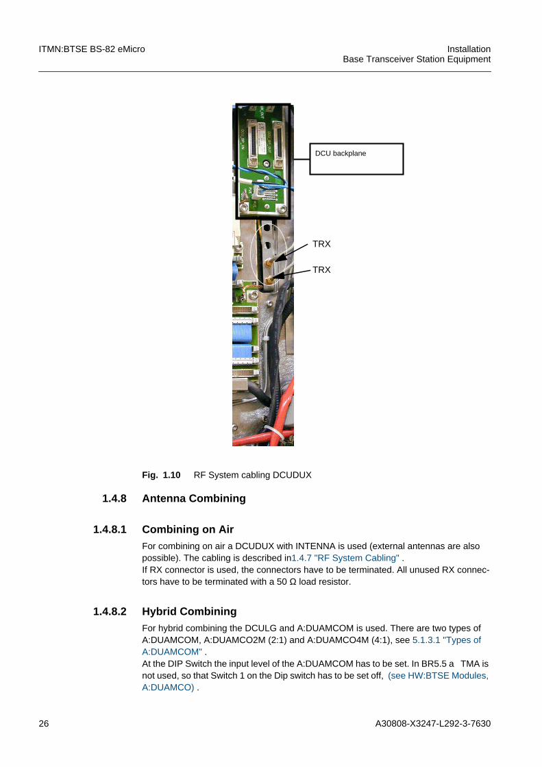
Fig. 1.10 RF System cabling DCUDUX
1.4.8 Antenna Combining
1.4.8.1 Combining on AirFor combining on air a DCUDUX with INTENNA is used (external antennas are alsopossible). The cabling is described in1.4.7 "RF System Cabling" .If RX connector is used, the connectors have to be terminated. All unused RX connec-tors have to be terminated with a 50 Ω load resistor.
1.4.8.2 Hybrid CombiningFor hybrid combining the DCULG and A:DUAMCOM is used. There are two types ofA:DUAMCOM, A:DUAMCO2M (2:1) and A:DUAMCO4M (4:1), see 5.1.3.1 "Types ofA:DUAMCOM" .At the DIP Switch the input level of the A:DUAMCOM has to be set. In BR5.5 a TMA isnot used, so that Switch 1 on the Dip switch has to be set off, (see HW:BTSE Modules,A:DUAMCO) .
DCU backplane
TRX
TRX
A30808-X3247-L292-3-7630 27
InstallationBase Transceiver Station Equipment
ITMN:BTSE BS-82 eMicro
The open TX inputs of A:DUAMCOM need not to be terminated in normal operation.
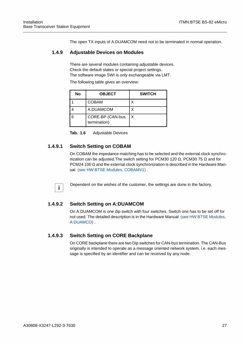
1.4.9 Adjustable Devices on Modules
There are several modules containing adjustable devices.Check the default states or special project settings.The software image SWI is only exchangeable via LMT.
The following table gives an overview:
1.4.9.1 Switch Setting on COBAMOn COBAM the impedance matching has to be selected and the external clock synchro-nization can be adjusted.The switch setting for PCM30 120 Ω, PCM30 75 Ω and forPCM24 100 Ω and the external clock synchronization is described in the Hardware Man-ual (see HW:BTSE Modules, COBAMV1) .
1.4.9.2 Switch Setting on A:DUAMCOMOn A:DUAMCOM is one dip switch with four switches. Switch one has to be set off fornot used. The detailed description is in the Hardware Manual (see HW:BTSE Modules,A:DUAMCO) .
1.4.9.3 Switch Setting on CORE BackplaneOn CORE backplane there are two Dip switches for CAN-bus termination. The CAN-Busoriginally is intended to operate as a message oriented network system, i.e. each mes-sage is specified by an identifier and can be received by any node.
No OBJECT SWITCH
1 COBAM X
4 A:DUAMCOM X
6 CORE-BP (CAN-bustermination)
X
Tab. 1.6 Adjustable Devices
iDependent on the wishes of the customer, the settings are done in the factory.
28 A30808-X3247-L292-3-7630
ITMN:BTSE BS-82 eMicro InstallationBase Transceiver Station Equipment
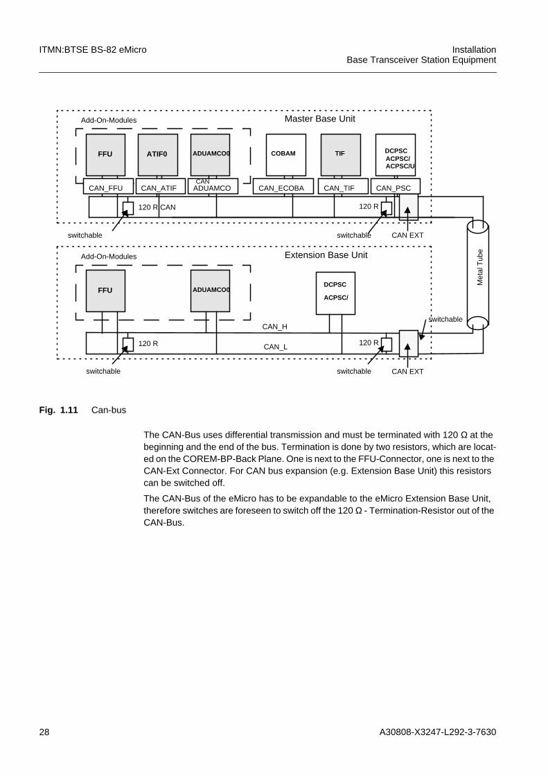
Fig. 1.11 Can-bus
The CAN-Bus uses differential transmission and must be terminated with 120 Ω at thebeginning and the end of the bus. Termination is done by two resistors, which are locat-ed on the COREM-BP-Back Plane. One is next to the FFU-Connector, one is next to theCAN-Ext Connector. For CAN bus expansion (e.g. Extension Base Unit) this resistorscan be switched off.
The CAN-Bus of the eMicro has to be expandable to the eMicro Extension Base Unit,therefore switches are foreseen to switch off the 120 Ω - Termination-Resistor out of theCAN-Bus.
Add-On-Modules
FFU ADUAMCO0ATIF0M:COBAM
TIFACPSC/DCPSC
switchable CAN EXT
120 R CAN 120 R
Master Base Unit
Add-On-Modules
FFU ADUAMCO0
COBAM
ACPSC/
DCPSC
switchable CAN EXT
switchable
120 R 120 R
Extension Base Unit
Met
alT
ube
CAN_FFU CAN_ATIF ADUAMCO CAN_ECOBA CAN_PSCCAN_TIFCAN
CAN_H
CAN_L
switchable
switchable
ACPSC/U

A30808-X3247-L292-3-7630 29
InstallationBase Transceiver Station Equipment
ITMN:BTSE BS-82 eMicro
Fig. 1.12 Can Bus Termination
1.4.10 Software
1.4.10.1 Boot Software (FW)Some modules contain special on-board boot software on EPROMs.
The allocations of the EPROMs are listed in the Release Note, part HW-FW Cross-ref-erence (for codes and positions on the module). The new boot software can be down-loaded via LMT.
1.4.10.2 Software Images SWISome modules receive the SWI via the LMT.
1 2
on on
Termination (on)
1 2
on on
Termination (off)
iOnly two 120Ω -Termination-Resistors (one at the beginning of the CAN bus and one atthe end of CAN bus) may be active on the CAN bus at the same time. The other Termi-nation-Resistors have to be switched off.
Module Board FILE NAME
CU bbix bbix01. swi
COBAM bbcx bbcx01. swi
Tab. 1.7 Boot Software
OBJECT FILE NAME
SWL hsxxxxxx. swl
depending on variant of ciphering
VAM vsxxxxxx. vam
depending on variant of ciphering
COBA BTSBCX01. SWI
CU BTSBIX01. SWI
Tab. 1.8 Software Images SWI
30 A30808-X3247-L292-3-7630
ITMN:BTSE BS-82 eMicro InstallationBase Transceiver Station Equipment
1.5 Preparation for Offline Tests
The purpose of this chapter is to execute all commissioning activities for
checking the delivery quality and quantity of the BTSE on site.
The following steps have to be executed to start the system:(refer to the relevant procedures)
1. Obtain the recommended tests and test equipment
2. Preparation of tests and test equipment
3. BTSE power on
4.Start of LMT
5. SW load
6. SW activation
7. Set RACK
8. Creation of HW related MO
9. Create BPORT
11. Set attributes for BTSE
12. Backup generation
13. BTSE phase 3
14. Offline tests
Finally the site must be accepted by the customer. On customer request, the HW func-tionality of the Network Entity has to be verified by following the steps described in therelevant Unit-ATMN prior to this acceptance.
A30808-X3247-L292-3-7630 31
InstallationBase Transceiver Station Equipment
ITMN:BTSE BS-82 eMicro
1.5.1 Recommended Test Equipment and Tools
Several devices, instruments, accessories and utensils have to beprovided and prepared for commissioning on site.
1.5.1.1 Test EquipmentThe equipment listed below has to be present for call simulation and verification of cor-rect operation.
Local Maintenance Terminal LMT
For detailed requirements refer to manual OGL:LMT.
Spectrum Analyser HP 8594A/E
MS_BS RF Coupling BOX
RF Termination
Depending on the BTSE and the equipped modules some RF terminations have to bepresent.
- HW:- HP8594A/E- Option:004/010/021/101/102/105
- SW:- GSM: HP 85715B Personality Card- DCS: HP 85722B Personality Card
- Cable:- BNC_male-SMA_male: e.g.RG58
- Adapter:- N_male-BNC_female
- HW:- MS Box- Coupling-Box
- Cable:- BNC_male-BNC_male (MS)- 3x:7/16_male-N_male (RX/TX)
- Adapter:- 7/16_male-N_male
- Tool:- Absorber 20dB/50Watt- 50 Ω Termination N_male
- TX/RX- 50 Ω SMA (A:DUAMCOM)
32 A30808-X3247-L292-3-7630
ITMN:BTSE BS-82 eMicro InstallationBase Transceiver Station Equipment
Mobile Station MS
Multimeter
1.5.1.2 ToolsSpecial tools for commissioning activities on site are listed below.
Antistatic Set
for ESD Module Handling
SMA Tool
with torque wrench for semi rigid Cable Connectors
Semi Rigid Bending Tool
for Semi rigid cable connection
TDMA Measuring Tools (Tests with HP 8594A/E) and Trigger Adapter
1.5.2 Preparation and Presetting of Test Equipment
1.5.2.1 Test EquipmentFor minimum test time and correct test results the deviceshave to be prepared on site.
Spectrum Analyzer
- HW:- mobile phone e.g. S25- PCS mobile phone, e.g. S40- Test Plug-In SIM
- HW:- SIEMENS Multimeter
- HW:- 2 Measuring cables with BNC-Plugs male (sufficient length)- Adapter SMA male - BNC female- Trigger adapter TAD-L at COBAM + TAD ADAPT
(50-pins AMP-Plug with 4 x BNC-Plug female- 1 Adapter N-Connector male - BNC female- HP 8590 series spectrum analyser operating manual- User´s Guide HP85715B GSM900 Transmitter Measurement Personality- User´s Guide HP 85722B DCS1800 Transmitter Measurement Personality
- HW: the HP8594A/E needs a warm-up time of 20 minutes depending on theavailable options.The display shows "OVEN COLD" during the heating phase. Afterwards a CAL-IBRATION has to be carried out for defined measurement execution.
- SW: The SW of GSM/DCS card has to be installed in advance.See analyzer operating manual for more detailed information.

A30808-X3247-L292-3-7630 33
InstallationBase Transceiver Station Equipment
ITMN:BTSE BS-82 eMicro
RF Termination
1.5.2.2 Software (SW)For all tests only released SW (corresponding to the BTSE HW/SW release) is allowedto be running on the test equipment (TE).
1.5.2.3 Boot Software/Firmware (SW/FW)For all tests only the released SW is allowed to be running on the BTSE correspondingto the BTSE HW/SW/FW release/revision.
1.5.3 BTSE Power ON
1.5.3.1 FusesDepending on the configuration of equipped DCU modules only the corresponding fuseshave to be switched on. The fuses are on the module ACPSC/DCPSC/ACPSC/U on thefrontside of the BS-82, (see HW:BTSE Modules, ACPSCV1) .
All other fuses are switched off.
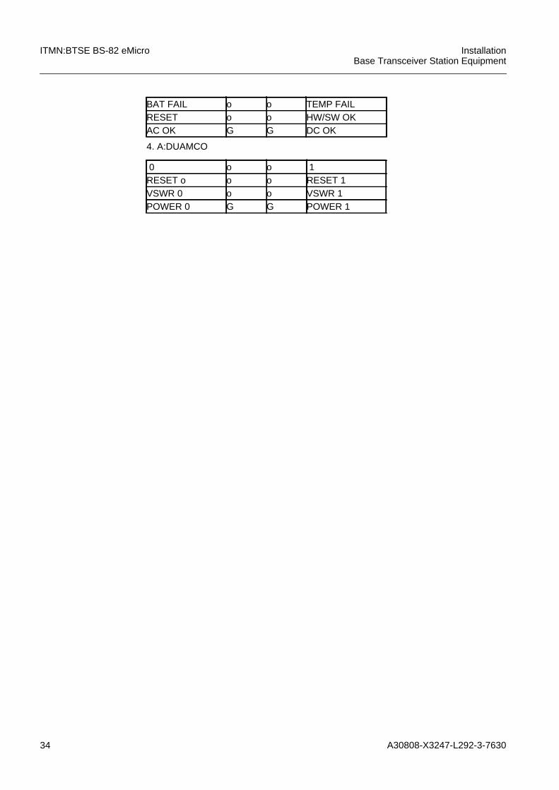
1.5.3.2 LED IndicationThe following LED description is only valid for the software installation.
The modules have the normal LED indication set as shown below for normal operation.
1.DCU
2.COBA
3.ACPSC/DCPSC
- HW:Before RF measurements are executed the following connectors have tobe terminated with 50 Ohm SMA resistors:- TX: open A:DUAMCOM outputs (SMA)- RX: open A:DUAMCOM inputs (SMA)
R redG greenfl(R) flashing redfl(G) flashing greeno off
OK fl(G) o SWRES o R PA
ACT fl(G) fl(R) RCOBAFLOC o o HMOABIS 1 o o ABIS 2
34 A30808-X3247-L292-3-7630
ITMN:BTSE BS-82 eMicro InstallationBase Transceiver Station Equipment
4. A:DUAMCO
BAT FAIL o o TEMP FAILRESET o o HW/SW OKAC OK G G DC OK
0 o o 1RESET o o o RESET 1VSWR 0 o o VSWR 1POWER 0 G G POWER 1
A30808-X3247-L292-3-7630 35
InstallationBase Transceiver Station Equipment
ITMN:BTSE BS-82 eMicro
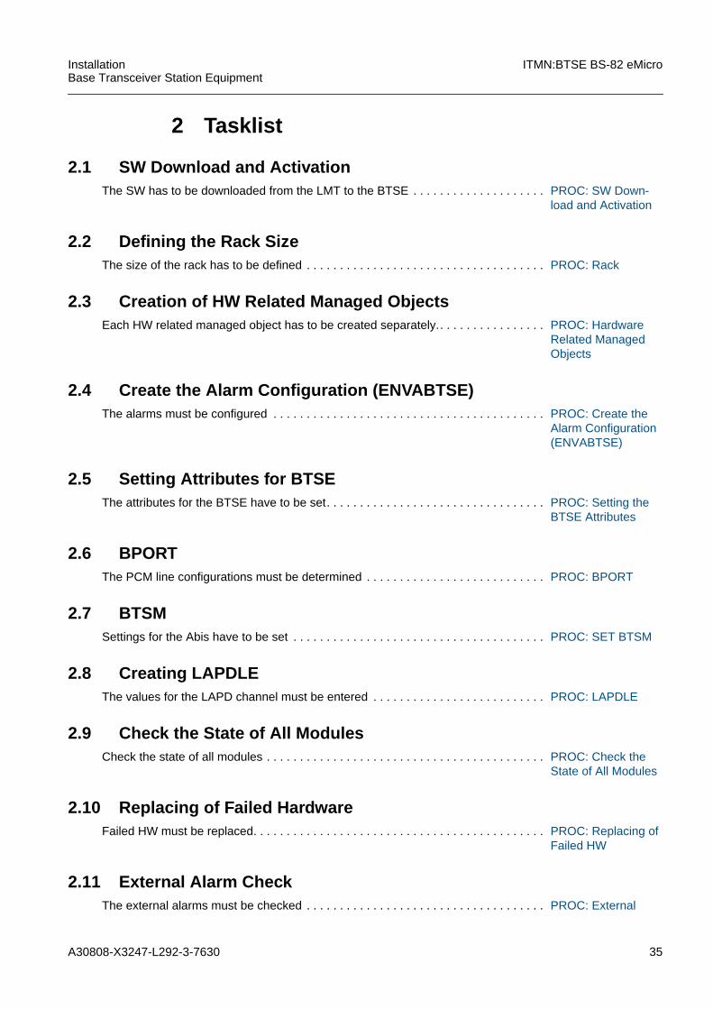
2 Tasklist
2.1 SW Download and ActivationThe SW has to be downloaded from the LMT to the BTSE . . . . . . . . . . . . . . . . . . . . PROC: SW Down-
load and Activation
2.2 Defining the Rack SizeThe size of the rack has to be defined . . . . . . . . . . . . . . . . . . . . . . . . . . . . . . . . . . . . PROC: Rack
2.3 Creation of HW Related Managed ObjectsEach HW related managed object has to be created separately.. . . . . . . . . . . . . . . . PROC: Hardware
Related ManagedObjects
2.4 Create the Alarm Configuration (ENVABTSE)The alarms must be configured . . . . . . . . . . . . . . . . . . . . . . . . . . . . . . . . . . . . . . . . . PROC: Create the
Alarm Configuration(ENVABTSE)
2.5 Setting Attributes for BTSEThe attributes for the BTSE have to be set. . . . . . . . . . . . . . . . . . . . . . . . . . . . . . . . . PROC: Setting the
BTSE Attributes
2.6 BPORTThe PCM line configurations must be determined . . . . . . . . . . . . . . . . . . . . . . . . . . . PROC: BPORT
2.7 BTSMSettings for the Abis have to be set . . . . . . . . . . . . . . . . . . . . . . . . . . . . . . . . . . . . . . PROC: SET BTSM
2.8 Creating LAPDLEThe values for the LAPD channel must be entered . . . . . . . . . . . . . . . . . . . . . . . . . . PROC: LAPDLE
2.9 Check the State of All ModulesCheck the state of all modules . . . . . . . . . . . . . . . . . . . . . . . . . . . . . . . . . . . . . . . . . . PROC: Check the
State of All Modules
2.10 Replacing of Failed HardwareFailed HW must be replaced. . . . . . . . . . . . . . . . . . . . . . . . . . . . . . . . . . . . . . . . . . . . PROC: Replacing of
Failed HW
2.11 External Alarm CheckThe external alarms must be checked . . . . . . . . . . . . . . . . . . . . . . . . . . . . . . . . . . . . PROC: External
36 A30808-X3247-L292-3-7630
ITMN:BTSE BS-82 eMicro InstallationBase Transceiver Station Equipment
Alarm Check
2.12 Generating BTS Backup FilesA backup of the configuration must be created . . . . . . . . . . . . . . . . . . . . . . . . . . . . . PROC: Generating
BTS Backup Files
2.13 Remote InventoryThe Remote Inventory data must be checked, added and copied for backup. . . . . . PROC: Remote In-
ventory
2.14 Changing the BTSE to Phase 3Change the BTSE from phase 2 to 3 . . . . . . . . . . . . . . . . . . . . . . . . . . . . . . . . . . . . . PROC: Switch to
Phase 3
A30808-X3247-L292-3-7630 37
InstallationBase Transceiver Station Equipment
ITMN:BTSE BS-82 eMicro
3 Procedures
38 A30808-X3247-L292-3-7630
ITMN:BTSE BS-82 eMicro InstallationBase Transceiver Station Equipment
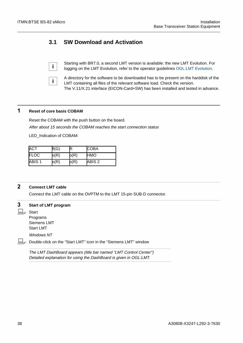
3.1 SW Download and Activation
1 Reset of core basis COBAM
Reset the COBAM with the push button on the board.
After about 15 seconds the COBAM reaches the start connection status
2 Connect LMT cable
Connect the LMT cable on the OVPTM to the LMT 15-pin SUB-D connector.
3 Start of LMT program
b StartProgramsSiemens LMTStart LMT
Windows NT
b Double-click on the “Start LMT” icon in the “Siemens LMT” window
The LMT DashBoard appears (title bar named “LMT Control Center")Detailed explanation for using the DashBoard is given in OGL:LMT.
iStarting with BR7.0, a second LMT version is available: the new LMT Evolution. Forlogging on the LMT Evolution, refer to the operator guidelines OGL:LMT Evolution.
iA directory for the software to be downloaded has to be present on the harddisk of theLMT containing all files of the relevant software load. Check the version.The V.11/X.21 interface (EICON-Card+SW) has been installed and tested in advance.
LED_Indication of COBAM:
ACT fl(G) R COBA
FLOC o(R) o(R) HMO
ABIS 1 o(R) o(R) ABIS 2

A30808-X3247-L292-3-7630 39
InstallationBase Transceiver Station Equipment
ITMN:BTSE BS-82 eMicro
4 Start connection to the BTSE
b Click on the “StartNet” button
The LMT Network Mode window appears. Select Local Machine or Remote bythe Network.
b Click on the "OK" button
The Session Starter window appears(Start new Session is pre-selected)
b Click on the “OK” button
The Logon Button in the MCDA window is activated
b Click on the “LOGON” button
The Logon Request window appears
b Enter UserID: <user>Enter Password: <password>Click on the “Connect” buttonClick on "Close"
The Logon Request window is closed
5 System response
The BTSE is now in phase 1
6 Start Input Handler
b Click on the “Input Hdl” button
The Input Handler window appears
7 SW download
b MANAGED-ELEMENTSOFTWARE-MANAGEMENTDNLALLEXESRCPATH=<path where the SW Load is stored on the LMT>OVERWRITE=yes
DNLALLEXE:SRCDIR="<path>\hs011207",OVERWRITE=YES;
Connection on Port 1
Logon ACK Received
40 A30808-X3247-L292-3-7630
ITMN:BTSE BS-82 eMicro InstallationBase Transceiver Station Equipment
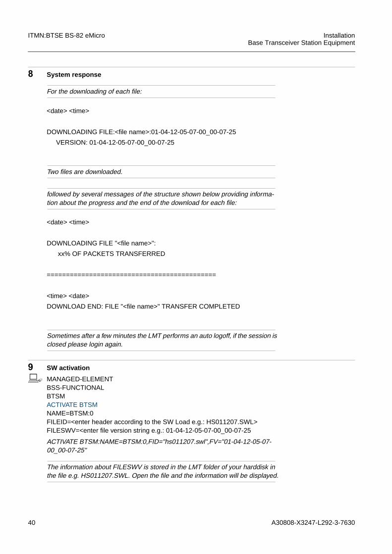
8 System response
For the downloading of each file:
Two files are downloaded.
followed by several messages of the structure shown below providing informa-tion about the progress and the end of the download for each file:
Sometimes after a few minutes the LMT performs an auto logoff, if the session isclosed please login again.
9 SW activation
b MANAGED-ELEMENTBSS-FUNCTIONALBTSMACTIVATE BTSMNAME=BTSM:0FILEID=<enter header according to the SW Load e.g.: HS011207.SWL>FILESWV=<enter file version string e.g.: 01-04-12-05-07-00_00-07-25
ACTIVATE BTSM:NAME=BTSM:0,FID="hs011207.swl",FV="01-04-12-05-07-00_00-07-25"
The information about FILESWV is stored in the LMT folder of your harddisk inthe file e.g. HS011207.SWL. Open the file and the information will be displayed.
<date> <time>
DOWNLOADING FILE:<file name>:01-04-12-05-07-00_00-07-25
VERSION: 01-04-12-05-07-00_00-07-25
<date> <time>
DOWNLOADING FILE "<file name>":
xx% OF PACKETS TRANSFERRED
============================================
<time> <date>
DOWNLOAD END: FILE "<file name>" TRANSFER COMPLETED

A30808-X3247-L292-3-7630 41
InstallationBase Transceiver Station Equipment
ITMN:BTSE BS-82 eMicro
10 System response
The session is now closed.
ACTSW BTSM:NAME=BTSM:0;FILEID="hs011207.swl",FILESWV="01-04-12-05-07-00_00-07-25";
<date> <time> Command
============================================
-----------------------------------------------------------------
JOB: <no>
PC Time&Date: <time> <date>
NE Time&date: <time> <date>
USER: <name>
COMMAND: Activate BTSM:NAME=BTSM:0,FILEID="Hs011302.swl",FILESWV="01-04-13-05-02-03_01-04-11";
SW RELEASE: 01-04-13-05-02-03_01-04-11
COMMAND RESULT: OPERATION COMPLETED
Activate BTSM SW ACK:
fileId = "Hs011302.swl"
fileVersion = "01-04-13-05-02-03_01-04-11"
END OF OUTPUT FOR JOB <no>
LED_Indication of COBAM:
ACT fl(G) o(R) COBA
FLOC o(G) o(R) HMO
ABIS 1 o(R) o(R) ABIS 2
42 A30808-X3247-L292-3-7630
ITMN:BTSE BS-82 eMicro InstallationBase Transceiver Station Equipment
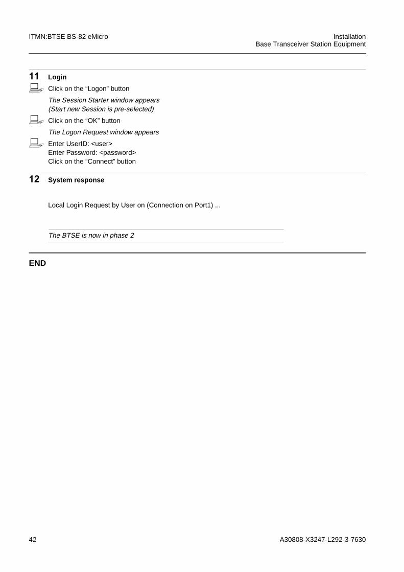
11 Login
b Click on the “Logon” button
The Session Starter window appears(Start new Session is pre-selected)
b Click on the “OK” button
The Logon Request window appears
b Enter UserID: <user>Enter Password: <password>Click on the “Connect” button
12 System response
The BTSE is now in phase 2
END
Local Login Request by User on (Connection on Port1) ...

A30808-X3247-L292-3-7630 43
InstallationBase Transceiver Station Equipment
ITMN:BTSE BS-82 eMicro
3.2 Hardware Related Managed Objects
1 Overview of the hardware related managed objects
END
iThe RACK must be set before HMOs are created!
NO. MODULE OBJECT (HEX) RANGE
1. RACK 17 0, 1
2. ACDCP 1d 0
3. ACT 11 0
4. BATTERY 19 0
5. COBA 13 0
6. CU 2 0...3
8. DILNA 16 0...3
10. DULNA 18 0, 1
11. DUVSWR 17 0...1
12. ENVABTSE 99 0...15
13. FANP 15 0
44 A30808-X3247-L292-3-7630
ITMN:BTSE BS-82 eMicro InstallationBase Transceiver Station Equipment
3.3 Rack
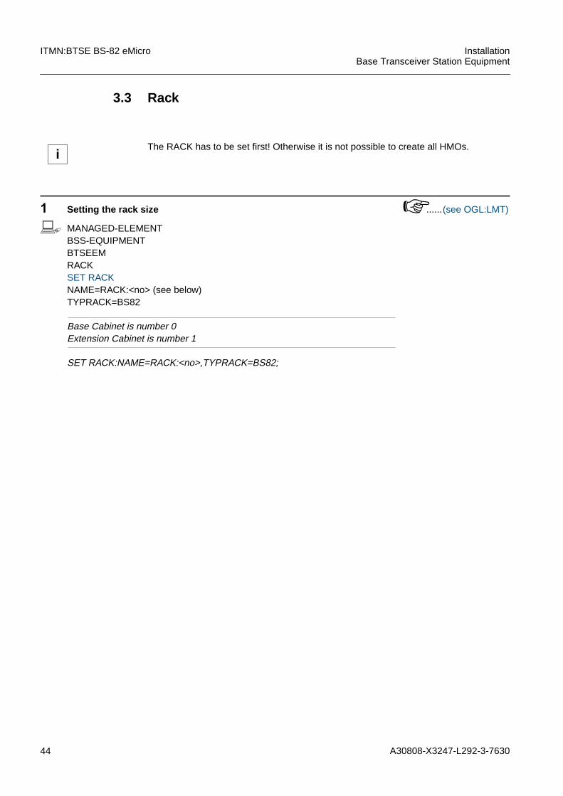
1 Setting the rack size ......(see OGL:LMT)
b MANAGED-ELEMENTBSS-EQUIPMENTBTSEEMRACKSET RACKNAME=RACK:<no> (see below)TYPRACK=BS82
Base Cabinet is number 0Extension Cabinet is number 1
SET RACK:NAME=RACK:<no>,TYPRACK=BS82;
iThe RACK has to be set first! Otherwise it is not possible to create all HMOs.
A30808-X3247-L292-3-7630 45
InstallationBase Transceiver Station Equipment
ITMN:BTSE BS-82 eMicro
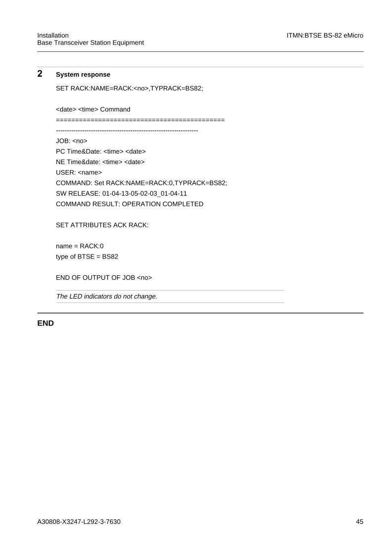
2 System response
The LED indicators do not change.
END
SET RACK:NAME=RACK:<no>,TYPRACK=BS82;
<date> <time> Command
============================================
-----------------------------------------------------------------
JOB: <no>
PC Time&Date: <time> <date>
NE Time&date: <time> <date>
USER: <name>
COMMAND: Set RACK:NAME=RACK:0,TYPRACK=BS82;
SW RELEASE: 01-04-13-05-02-03_01-04-11
COMMAND RESULT: OPERATION COMPLETED
SET ATTRIBUTES ACK RACK:
name = RACK:0
type of BTSE = BS82
END OF OUTPUT OF JOB <no>

46 A30808-X3247-L292-3-7630
ITMN:BTSE BS-82 eMicro InstallationBase Transceiver Station Equipment
3.4 ACDCP
1 ACDCP creation ......(see OGL:LMT)
The following action has to be repeated for each equipped module.
b MANAGED-ELEMENTBSS-EQUIPMENTBTSEEMRACKACDCPCREATE ACDCPNAME=RACK:<no>/ACDCP:<no>
CREATE ACDCP:NAME=RACK:<no>/ACDCP:<no>
iThe ACDCP creation is required only with AC-power supply.
A30808-X3247-L292-3-7630 47
InstallationBase Transceiver Station Equipment
ITMN:BTSE BS-82 eMicro
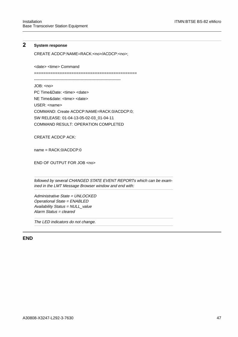
2 System response
followed by several CHANGED STATE EVENT REPORTs which can be exam-ined in the LMT Message Browser window and end with:
Administrative State = UNLOCKEDOperational State = ENABLEDAvailability Status = NULL_valueAlarm Status = cleared
The LED indicators do not change.
END
CREATE ACDCP:NAME=RACK:<no>/ACDCP:<no>;
<date> <time> Command
============================================
-----------------------------------------------------------------
JOB: <no>
PC Time&Date: <time> <date>
NE Time&date: <time> <date>
USER: <name>
COMMAND: Create ACDCP:NAME=RACK:0/ACDCP:0;
SW RELEASE: 01-04-13-05-02-03_01-04-11
COMMAND RESULT: OPERATION COMPLETED
CREATE ACDCP ACK:
name = RACK:0/ACDCP:0
END OF OUTPUT FOR JOB <no>
48 A30808-X3247-L292-3-7630
ITMN:BTSE BS-82 eMicro InstallationBase Transceiver Station Equipment
3.5 ACT
ACT creation is necessary for AC- and DC-power supply.
To activate the Alarm Collection Terminal the HMO ACT has to be created in eachRack.
1 ACT creation ......(see OGL:LMT)
b MANAGED-ELEMENTBSS-EQUIPMENTBTSEEMRACKACTCREATE ACTNAME=RACK:<no>/ACT:<no>
Check the correct Rack numbering.
CREATE ACT:NAME=RACK:<no>/ACT:<no>;
iSet the correct Rack adress for each Rack! Master Cabinet is number 0 and ExtensionCabinet is number 1.
iACT is a software but not a real hardware module.
A30808-X3247-L292-3-7630 49
InstallationBase Transceiver Station Equipment
ITMN:BTSE BS-82 eMicro
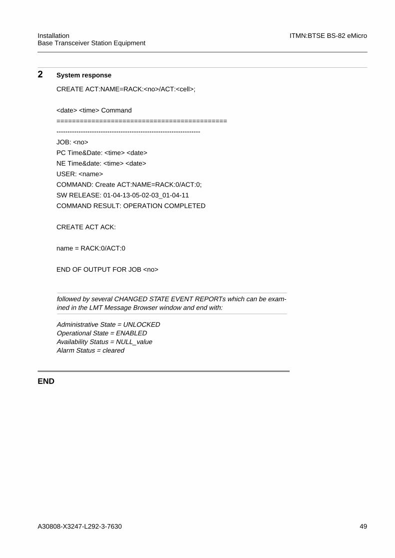
2 System response
followed by several CHANGED STATE EVENT REPORTs which can be exam-ined in the LMT Message Browser window and end with:
Administrative State = UNLOCKEDOperational State = ENABLEDAvailability Status = NULL_valueAlarm Status = cleared
END
CREATE ACT:NAME=RACK:<no>/ACT:<cell>;
<date> <time> Command
============================================
-----------------------------------------------------------------
JOB: <no>
PC Time&Date: <time> <date>
NE Time&date: <time> <date>
USER: <name>
COMMAND: Create ACT:NAME=RACK:0/ACT:0;
SW RELEASE: 01-04-13-05-02-03_01-04-11
COMMAND RESULT: OPERATION COMPLETED
CREATE ACT ACK:
name = RACK:0/ACT:0
END OF OUTPUT FOR JOB <no>
50 A30808-X3247-L292-3-7630
ITMN:BTSE BS-82 eMicro InstallationBase Transceiver Station Equipment
3.6 BATTERY
The rack can optionally be equipped with backup batteries. The internal batteries guar-antee continuos operation in case of main breakdown or AC/DC failure.
1 BATTERY creation ......(see OGL:LMT)
b MANAGED-ELEMENTBSS-EQUIPMENTBTSEEMBATTERYCREATE BATTERYNAME=RACK:<no>/BATTERY:<no>
Check the correct Rack numbering.
CREATE BATTERY:NAME=RACK:<no>/BATTERY:<no>;

A30808-X3247-L292-3-7630 51
InstallationBase Transceiver Station Equipment
ITMN:BTSE BS-82 eMicro
2 System response
followed by several CHANGED STATE EVENT REPORTs which can be exam-ined in the LMT Message Browser window and end with:
Administrative State = UNLOCKEDOperational State = ENABLEDAvailability Status = NULL_valueAlarm Status = cleared
END
CREATE BATTERY:NAME=RACK:<no>/BATTERY:0;
<date> <time> Command
============================================
-----------------------------------------------------------------
JOB: <no>
PC Time&Date: <time> <date>
NE Time&date: <time> <date>
USER: <name>
COMMAND: Create BATTERY:NAME=RACK:0/BATTERY:0;
SW RELEASE: 01-04-13-05-02-03_01-04-11
COMMAND RESULT: OPERATION COMPLETED
CREATE BATTERY ACK:
name = RACK:0/BATTERY:0
END OF OUTPUT FOR JOB <no>
52 A30808-X3247-L292-3-7630
ITMN:BTSE BS-82 eMicro InstallationBase Transceiver Station Equipment
3.7 COBA
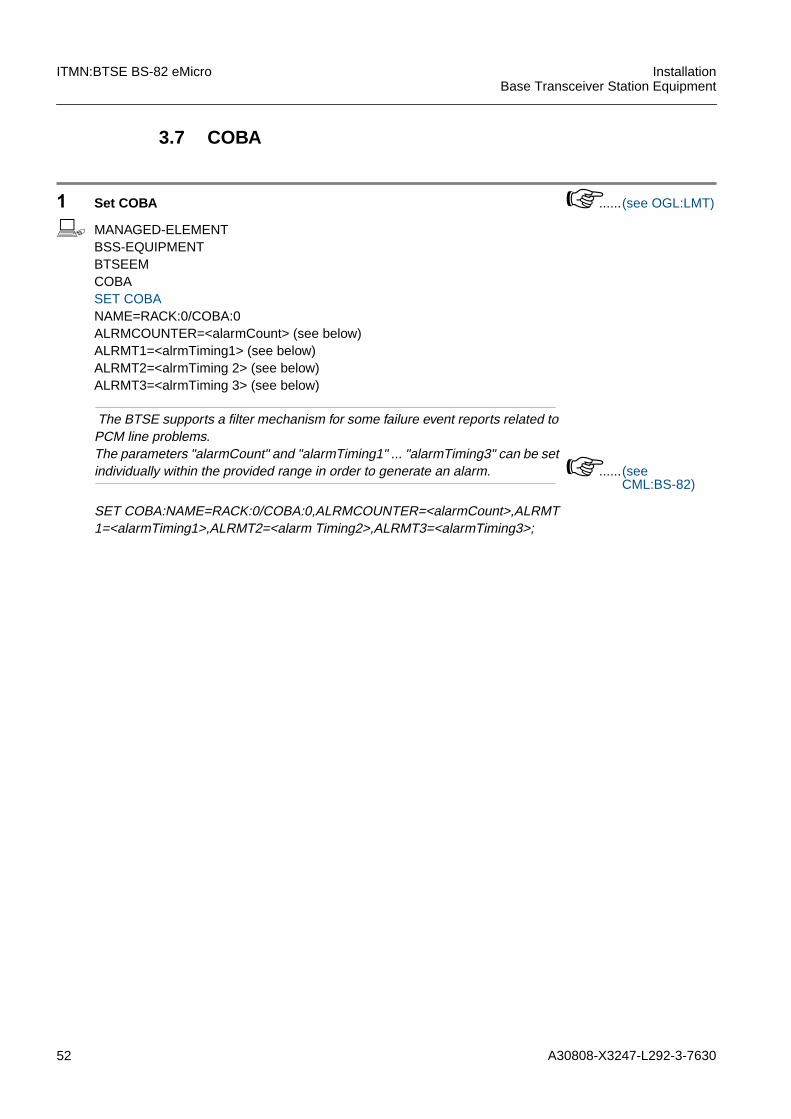
1 Set COBA ......(see OGL:LMT)
b MANAGED-ELEMENTBSS-EQUIPMENTBTSEEMCOBASET COBANAME=RACK:0/COBA:0ALRMCOUNTER=<alarmCount> (see below)ALRMT1=<alrmTiming1> (see below)ALRMT2=<alrmTiming 2> (see below)ALRMT3=<alrmTiming 3> (see below)
The BTSE supports a filter mechanism for some failure event reports related toPCM line problems.The parameters "alarmCount" and "alarmTiming1" ... "alarmTiming3" can be setindividually within the provided range in order to generate an alarm. ......(see
CML:BS-82)
SET COBA:NAME=RACK:0/COBA:0,ALRMCOUNTER=<alarmCount>,ALRMT1=<alarmTiming1>,ALRMT2=<alarm Timing2>,ALRMT3=<alarmTiming3>;
A30808-X3247-L292-3-7630 53
InstallationBase Transceiver Station Equipment
ITMN:BTSE BS-82 eMicro
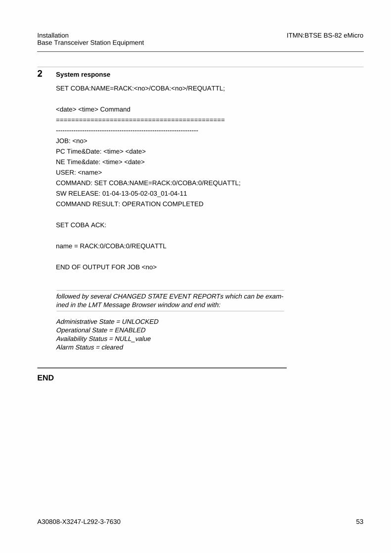
2 System response
followed by several CHANGED STATE EVENT REPORTs which can be exam-ined in the LMT Message Browser window and end with:
Administrative State = UNLOCKEDOperational State = ENABLEDAvailability Status = NULL_valueAlarm Status = cleared
END
SET COBA:NAME=RACK:<no>/COBA:<no>/REQUATTL;
<date> <time> Command
============================================
-----------------------------------------------------------------
JOB: <no>
PC Time&Date: <time> <date>
NE Time&date: <time> <date>
USER: <name>
COMMAND: SET COBA:NAME=RACK:0/COBA:0/REQUATTL;
SW RELEASE: 01-04-13-05-02-03_01-04-11
COMMAND RESULT: OPERATION COMPLETED
SET COBA ACK:
name = RACK:0/COBA:0/REQUATTL
END OF OUTPUT FOR JOB <no>

54 A30808-X3247-L292-3-7630
ITMN:BTSE BS-82 eMicro InstallationBase Transceiver Station Equipment
3.8 DCU
The Master Cabinet and Extension Cabinet can be equipped with 2 DCU modules. Thenumbering is described in 1.4.4 "Numbering of Modules and Hardware Managed Ob-jects". Each DCU contains the following HMOs:
iCU
DILNA
Each DCU contains two HMOs CU. The CU objects have tobe handled separately.
This HMO supplies the low noise amplifying. For each cre-ated CU the HMO DILNA has to be created.
A30808-X3247-L292-3-7630 55
InstallationBase Transceiver Station Equipment
ITMN:BTSE BS-82 eMicro
1 CU creation ...... (see OGL:LMT)
The following action has to be repeated for each equipped module.
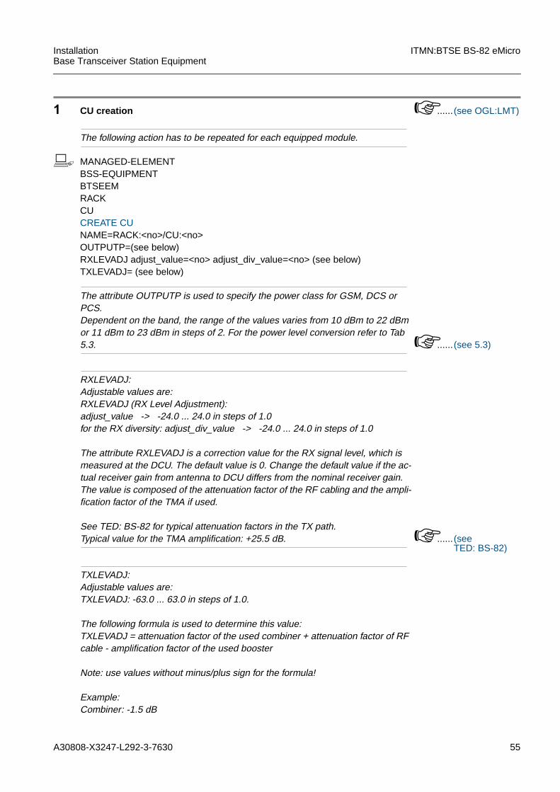
b MANAGED-ELEMENTBSS-EQUIPMENTBTSEEMRACKCUCREATE CUNAME=RACK:<no>/CU:<no>OUTPUTP=(see below)RXLEVADJ adjust_value=<no> adjust_div_value=<no> (see below)TXLEVADJ= (see below)
The attribute OUTPUTP is used to specify the power class for GSM, DCS orPCS.Dependent on the band, the range of the values varies from 10 dBm to 22 dBmor 11 dBm to 23 dBm in steps of 2. For the power level conversion refer to Tab5.3. ...... (see 5.3)
RXLEVADJ:Adjustable values are:RXLEVADJ (RX Level Adjustment):adjust_value -> -24.0 ... 24.0 in steps of 1.0for the RX diversity: adjust_div_value -> -24.0 ... 24.0 in steps of 1.0
The attribute RXLEVADJ is a correction value for the RX signal level, which ismeasured at the DCU. The default value is 0. Change the default value if the ac-tual receiver gain from antenna to DCU differs from the nominal receiver gain.The value is composed of the attenuation factor of the RF cabling and the ampli-fication factor of the TMA if used.
See TED: BS-82 for typical attenuation factors in the TX path.Typical value for the TMA amplification: +25.5 dB. ...... (see
TED: BS-82)
TXLEVADJ:Adjustable values are:TXLEVADJ: -63.0 ... 63.0 in steps of 1.0.
The following formula is used to determine this value:TXLEVADJ = attenuation factor of the used combiner + attenuation factor of RFcable - amplification factor of the used booster
Note: use values without minus/plus sign for the formula!
Example:Combiner: -1.5 dB
56 A30808-X3247-L292-3-7630
ITMN:BTSE BS-82 eMicro InstallationBase Transceiver Station Equipment
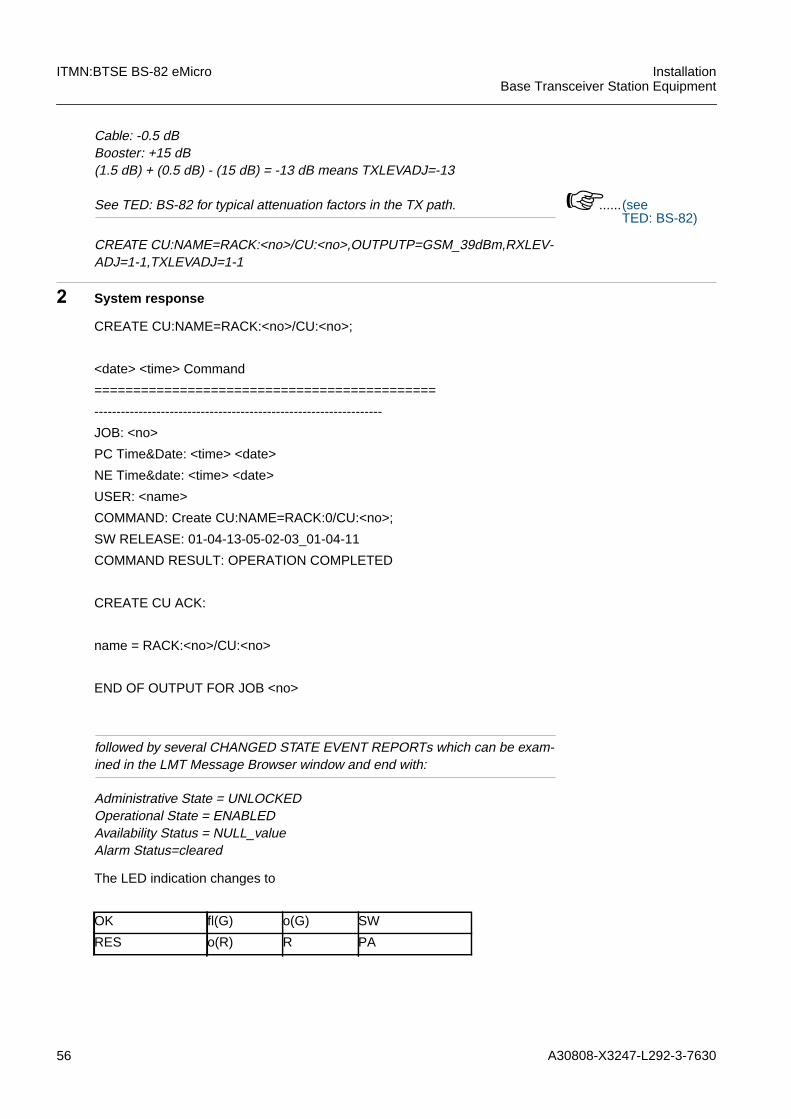
Cable: -0.5 dBBooster: +15 dB(1.5 dB) + (0.5 dB) - (15 dB) = -13 dB means TXLEVADJ=-13
See TED: BS-82 for typical attenuation factors in the TX path. ......(seeTED: BS-82)
CREATE CU:NAME=RACK:<no>/CU:<no>,OUTPUTP=GSM_39dBm,RXLEV-ADJ=1-1,TXLEVADJ=1-1
2 System response
followed by several CHANGED STATE EVENT REPORTs which can be exam-ined in the LMT Message Browser window and end with:
Administrative State = UNLOCKEDOperational State = ENABLEDAvailability Status = NULL_valueAlarm Status=cleared
CREATE CU:NAME=RACK:<no>/CU:<no>;
<date> <time> Command
============================================
-----------------------------------------------------------------
JOB: <no>
PC Time&Date: <time> <date>
NE Time&date: <time> <date>
USER: <name>
COMMAND: Create CU:NAME=RACK:0/CU:<no>;
SW RELEASE: 01-04-13-05-02-03_01-04-11
COMMAND RESULT: OPERATION COMPLETED
CREATE CU ACK:
name = RACK:<no>/CU:<no>
END OF OUTPUT FOR JOB <no>
The LED indication changes to
OK fl(G) o(G) SW
RES o(R) R PA
A30808-X3247-L292-3-7630 57
InstallationBase Transceiver Station Equipment
ITMN:BTSE BS-82 eMicro
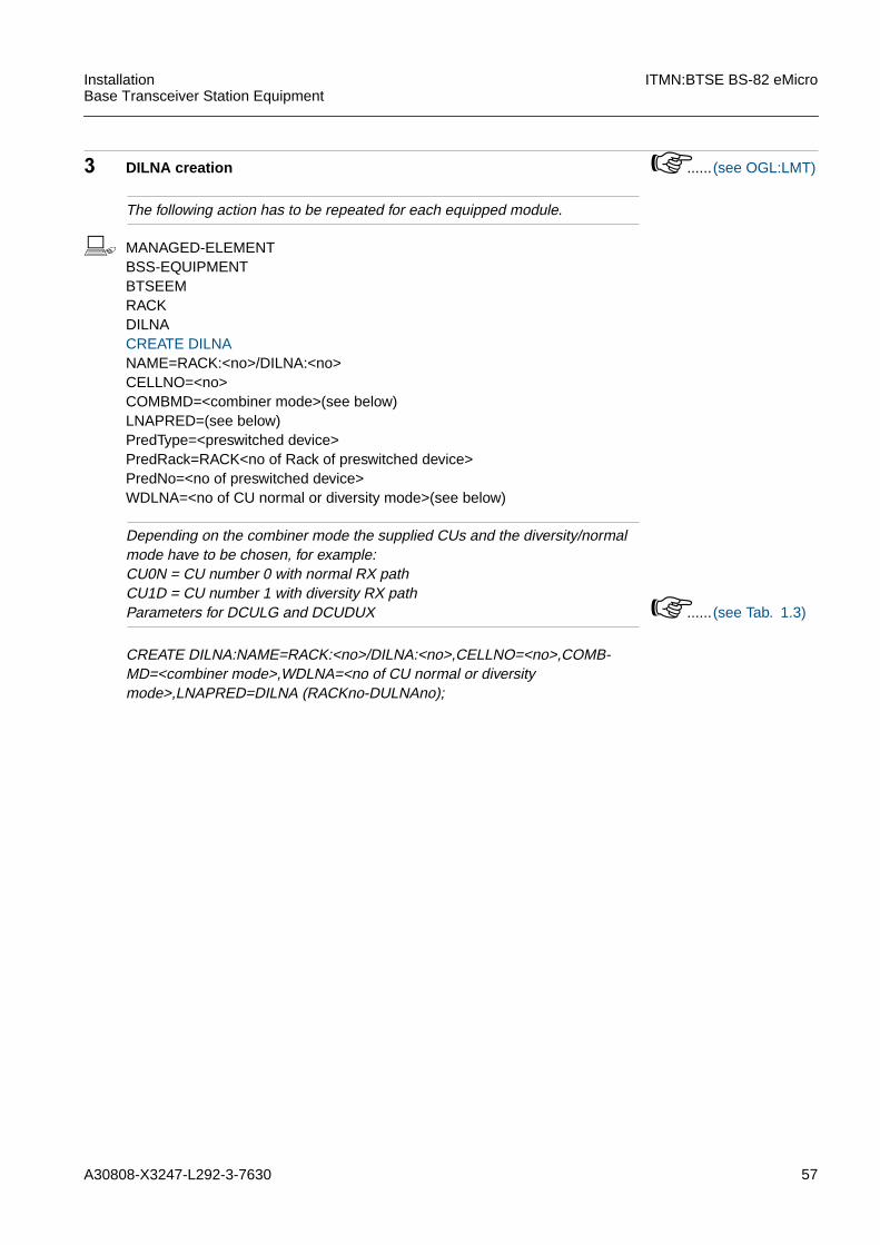
3 DILNA creation ...... (see OGL:LMT)
The following action has to be repeated for each equipped module.
b MANAGED-ELEMENTBSS-EQUIPMENTBTSEEMRACKDILNACREATE DILNANAME=RACK:<no>/DILNA:<no>CELLNO=<no>COMBMD=<combiner mode>(see below)LNAPRED=(see below)PredType=<preswitched device>PredRack=RACK<no of Rack of preswitched device>PredNo=<no of preswitched device>WDLNA=<no of CU normal or diversity mode>(see below)
Depending on the combiner mode the supplied CUs and the diversity/normalmode have to be chosen, for example:CU0N = CU number 0 with normal RX pathCU1D = CU number 1 with diversity RX pathParameters for DCULG and DCUDUX ...... (see Tab. 1.3)
CREATE DILNA:NAME=RACK:<no>/DILNA:<no>,CELLNO=<no>,COMB-MD=<combiner mode>,WDLNA=<no of CU normal or diversitymode>,LNAPRED=DILNA (RACKno-DULNAno);
58 A30808-X3247-L292-3-7630
ITMN:BTSE BS-82 eMicro InstallationBase Transceiver Station Equipment
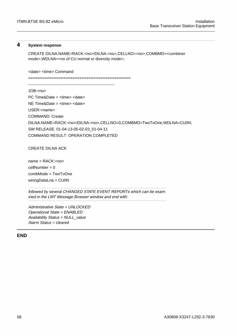
4 System response
followed by several CHANGED STATE EVENT REPORTs which can be exam-ined in the LMT Message Browser window and end with:
Administrative State = UNLOCKEDOperational State = ENABLEDAvailability Status = NULL_valueAlarm Status = cleared
END
CREATE DILNA:NAME=RACK:<no>/DILNA:<no>,CELLNO=<no>,COMBMD=<combinermode>,WDLNA=<no of CU normal or diversity mode>;
<date> <time> Command
============================================
-----------------------------------------------------------------
JOB:<no>
PC Time&Date = <time> <date>
NE Time&Date = <time> <date>
USER:<name>
COMMAND: Create
DILNA:NAME=RACK:<no>/DILNA:<no>,CELLNO=0,COMBMD=TwoToOne,WDLNA=CU0N;
SW RELEASE: 01-04-13-05-02-03_01-04-11
COMMAND RESULT: OPERATION COMPLETED
CREATE DILNA ACK
name = RACK:<no>
cellNumber = 0
combMode = TwoToOne
wiringDataLna = CU0N

A30808-X3247-L292-3-7630 59
InstallationBase Transceiver Station Equipment
ITMN:BTSE BS-82 eMicro
3.9 A:DUAMCO
The DCULGx is used in case of hybrid combining together with A:DUAMCOxM.For use of A:DUAMCOM the following HMOs have to be created, see also1.4.4 "Numbering of Modules and Hardware Managed Objects".
1 DUVSWR creation ...... (see OGL:LMT)
The following action has to be repeated for all equipped modules.
b MANAGED-ELEMENTBSS-EQUIPMENTBTSEEMRACKDUVSWRCREATE DUVSWRNAME=RACK:<no>/DUVSWR:<no>CELLNO=<no>WDDUVSWR=<no of CU>COMBMD=<combiner mode>
The combiner mode depends on the DUAMCO Type. DUAMCO 2:1 means that1 antenna can be connected and 2 RX/TX paths are available for each side ofA:DUAMCO.
CREATE DUVSWR:NAME=RACK:<no>/DUVSWR:<no>,CELLNO=<no>WDDUVSWR=<no of CU>,COMBMD=<combiner mode>;
iNo TMA in BR6.0, so switch 1 on A:DUAMCOM has to be set off.
DUVSWR This HMO supplies the VSWR logic . There is one managedobject of this type per A:DUAMCOM.
DULNA This HMO supplies the Low Noise Amplifying in the RX path ofthe A:DUAMCOM. It has to be created for each A:DUAM-COM.
iThe numbering of DUVSWR and DULNA for extension rack starts with 0. Todistinguish DULNA0 master cabinet from DULNA0 extension cabinet therack number has to be set.
60 A30808-X3247-L292-3-7630
ITMN:BTSE BS-82 eMicro InstallationBase Transceiver Station Equipment
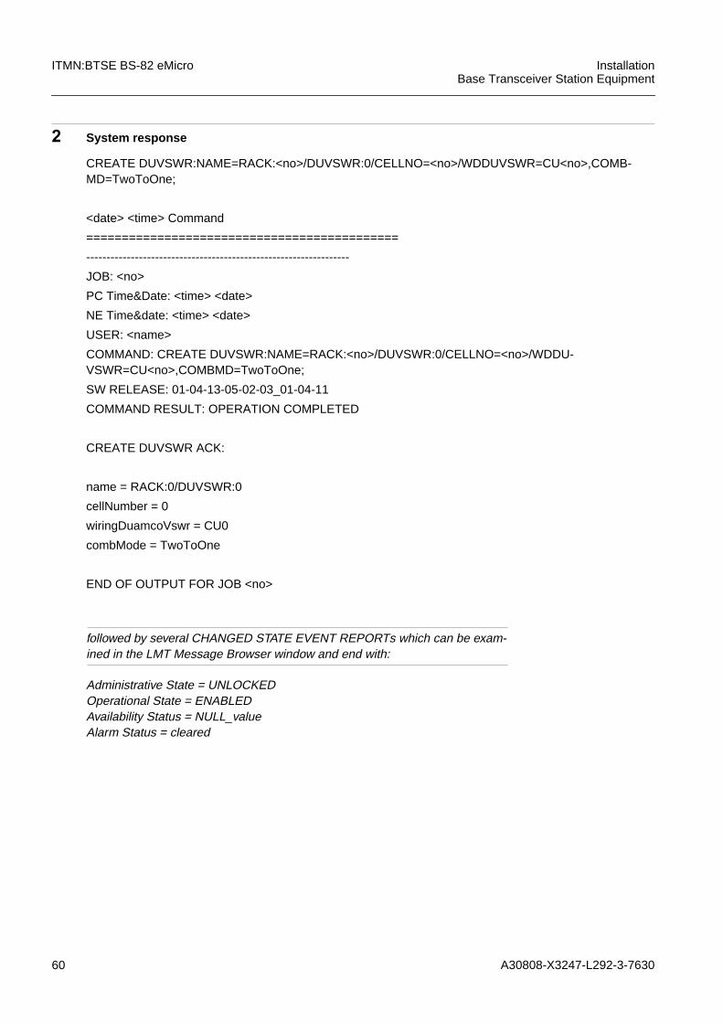
2 System response
followed by several CHANGED STATE EVENT REPORTs which can be exam-ined in the LMT Message Browser window and end with:
Administrative State = UNLOCKEDOperational State = ENABLEDAvailability Status = NULL_valueAlarm Status = cleared
CREATE DUVSWR:NAME=RACK:<no>/DUVSWR:0/CELLNO=<no>/WDDUVSWR=CU<no>,COMB-MD=TwoToOne;
<date> <time> Command
============================================
-----------------------------------------------------------------
JOB: <no>
PC Time&Date: <time> <date>
NE Time&date: <time> <date>
USER: <name>
COMMAND: CREATE DUVSWR:NAME=RACK:<no>/DUVSWR:0/CELLNO=<no>/WDDU-VSWR=CU<no>,COMBMD=TwoToOne;
SW RELEASE: 01-04-13-05-02-03_01-04-11
COMMAND RESULT: OPERATION COMPLETED
CREATE DUVSWR ACK:
name = RACK:0/DUVSWR:0
cellNumber = 0
wiringDuamcoVswr = CU0
combMode = TwoToOne
END OF OUTPUT FOR JOB <no>

A30808-X3247-L292-3-7630 61
InstallationBase Transceiver Station Equipment
ITMN:BTSE BS-82 eMicro
3 DULNA creation ...... (see OGL:LMT)
The following action has to be repeated for all equipped modules.
b MANAGED-ELEMENTBSS-EQUIPMENTBTSEEMRACKDULNACREATE DULNANAME=RACK:<no>/DULNA:<no>CELLNO=<no>COMBMD=<combiner mode>WDLNA=<no of CU normal or diversity mode>(see below)LNAPRED=(see below)PredType=<preswitched device>PredRack=RACK<no of Rack of cascaded device>PredNo=<no of cascaded device>
The combiner mode depends on the DUAMCO Type. DUAMCO 4:1 means that1 antenna can be connected and 4 RX/TX pathes are available at A:DUAM-COM.
CREATE DULNA:NAME=RACK:<no>/DULNA:<no>,CELLNO=<no>,COMBMD=<combiner mode>,LNAPRED=DULNA (RACK<no>-DULNA<no>;
62 A30808-X3247-L292-3-7630
ITMN:BTSE BS-82 eMicro InstallationBase Transceiver Station Equipment
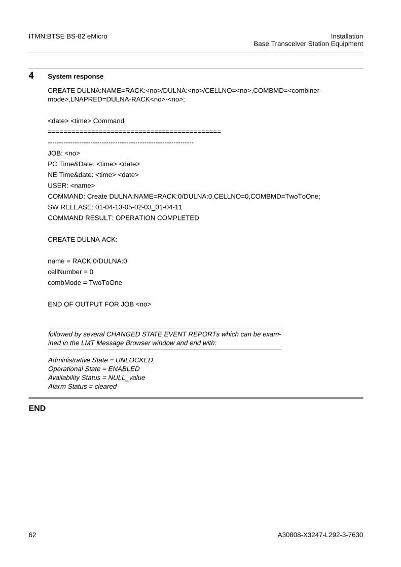
4 System response
followed by several CHANGED STATE EVENT REPORTs which can be exam-ined in the LMT Message Browser window and end with:
Administrative State = UNLOCKEDOperational State = ENABLEDAvailability Status = NULL_valueAlarm Status = cleared
END
CREATE DULNA:NAME=RACK:<no>/DULNA:<no>/CELLNO=<no>,COMBMD=<combiner-mode>,LNAPRED=DULNA-RACK<no>-<no>;
<date> <time> Command
============================================
-----------------------------------------------------------------
JOB: <no>
PC Time&Date: <time> <date>
NE Time&date: <time> <date>
USER: <name>
COMMAND: Create DULNA:NAME=RACK:0/DULNA:0,CELLNO=0,COMBMD=TwoToOne;
SW RELEASE: 01-04-13-05-02-03_01-04-11
COMMAND RESULT: OPERATION COMPLETED
CREATE DULNA ACK:
name = RACK:0/DULNA:0
cellNumber = 0
combMode = TwoToOne
END OF OUTPUT FOR JOB <no>
A30808-X3247-L292-3-7630 63
InstallationBase Transceiver Station Equipment
ITMN:BTSE BS-82 eMicro
3.10 FANP
Each Rack is equipped with 1 Fan. During the creation of the Fan the Alarm for a defectFan is generated automatically.
1 FANP creation ...... (see OGL:LMT)
The following action has to be repeated for each equipped module.
b MANAGED-ELEMENTBSS-EQUIPMENTBTSEEMRACKFANPCREATE FANPNAME=RACK:<no>/FANP:<no>
CREATE FANP:NAME=RACK:<no>/FANP:<no>;
2 System response
END
CREATE FANP:NAME=RACK:<no>/FANP:0;
<date> <time> Command
============================================
-----------------------------------------------------------------
JOB: <no>
PC Time&Date: <time> <date>
NE Time&date: <time> <date>
USER: <name>
COMMAND: Create FANP:NAME=RACK:0/FANP:0;
SW RELEASE: 01-04-13-05-02-03_01-04-11
COMMAND RESULT: OPERATION COMPLETED
CREATE FANP ACK:
name = RACK:0/FANP:0
END OF OUTPUT FOR JOB <no>
64 A30808-X3247-L292-3-7630
ITMN:BTSE BS-82 eMicro InstallationBase Transceiver Station Equipment
3.11 Create the Alarm Configuration (ENVABTSE)
Each Rack is equipped with ACT (ACPSC/DCPSC/ACPSC/U) that supplies 16 ENVAs.The pinning is described in the introduction, see1.3.5 "Operator Alarms".The alarms for "FAN" and "Rack Door open" are created automatically during the cre-ation of FAN and SET RACK.
For more information refer to CML:BS-82 eMicro and MMN:BS-82
1 ENVABTSE creation ......(see OGL:LMT)
The following action has to be repeated for each environmental alarm.
b MANAGED-ELEMENTBSS-EQUIPMENTBTSEEMRACKENVABTSECREATE ENVABTSENAME=RACK:<no>/ENVABTSE:<no>(see below)INTINF=<interfaceInformation>(see below)ASEV=<associatedSeverity>(see below)ASTRING=<associatedString>
ENVA 0 ... ENVA 15 can be configured by the operator!
The alarms can be configured as high active or low active:high active : alarm message starts if the pins are openedlow active: alarm message starts if the pins are closed by short circuit
Alarm severity level can be chosen (critical, major, minor) or it can be read out ofthe database (default_db).
CREATE ENVABTSE:NAME=RACK:<no>/ENVABTSE:<no>,INTINF=low,ASEV=DEFAULT_DB,ASTRING="Fire";
iVia LMT there are 22 ENVAs available, only the ENVA 0... ENVA 15 can be defined bythe operator! ENVA 16-21 has to be defined if a TIF-module (e.g. A:TIFNTPM) is in use!For the BS-82 all ENVAs can be left as “not equipped”.
A30808-X3247-L292-3-7630 65
InstallationBase Transceiver Station Equipment
ITMN:BTSE BS-82 eMicro
2 System response
There is no change of LED indication.
END
CREATE ENVABTSE:NAME=RACK:<no>/ENVABTSE:0/INTINF=HIGH;ASEV=MAJOR,AS-TRING=<name>;
<date> <time> Command
============================================
-----------------------------------------------------------------
JOB: <no>
PC Time&Date: <time> <date>
NE Time&date: <time> <date>
USER: <name>
COMMAND: Create ENVABTSE:NAME=RACK:0/ENVABTSE:0/INTINF=HIGH/ASEV=MAJOR/AS-TRING=<name>;
SW RELEASE: 01-04-13-05-02-03_01-04-11
COMMAND RESULT: OPERATION COMPLETED
CREATE ENVABTSE ACK:
name = RACK:0/ENVABTSE:0
associatedSeverity = MAJOR
associatedString = <name>
interfaceInformation = high
END OF OUTPUT FOR JOB <no>

66 A30808-X3247-L292-3-7630
ITMN:BTSE BS-82 eMicro InstallationBase Transceiver Station Equipment
3.12 Setting the BTSE Attributes
The location name, the vendor name, the sales unique name and the software loadsafety have to be set. For more information refer to CML:BS-82 eMicro
1 Set attributes for BTSE equipment ......(see OGL:LMT)
b MANAGED-ELEMENTBSS-EQUIPMENTBTSEEMSET BTSEEMNAME=BTSEEM:0BASICSEQUPOS=<SBS_Equipment_Position>CHIDT=ChangeOnIDT/NoChanceOnIDTEAUTOREC=enabled/disabledLOCNAME=<locationName>RXDIVSV=enabled/disabledSALUNAME=<salesUniqueName>(see below)VENDNA=<vendorName>SEVERITYALRMSEVACDCP=critical/major/minor/Default DBALRMSEVACT...=critical/major/minor/Default DBALRMSEVBATTERY=critical/major/minor/Default DBALRMSEVCOBA=critical/major/minor/Default DBALRMSEVCU=critical/major/minor/Default DBALRMSEVDILNA=critical/major/minor/Default DBALRMSEVDULNA=critical/major/minor/Default DBALRMSEVDUVWSR=critical/major/minor/Default DBALRMSEVFANP=critical/major/minor/Default DBSWLSWLDSAF=<swLoadSafety: swLoadSafetyField, swLoadSafetyVersion>
The SWLDSAF has to be set after the connecting the BTSE with the BSC.
The Sales unique name (= old Vst-ID or Exchange Code) is defined by SIE-MENS cental service TSC3 and provided to the commissioners by local TSC2.It is a ASCII character string with length 11,e.g: "AD042S7449E".
SET BTSE:NAME=BTSE:0,LOCNAME="Munich",RXDIVSV=enabled,SALUNA-ME="AD042S7449E"SWLDSAF="hs011207.swl: 01-01-08-00-08-00_98-08-21",VENDNA="Siemens";
iFor Remote Inventory the SALUNAME and BSTEPOS have to be set correctly.
A30808-X3247-L292-3-7630 67
InstallationBase Transceiver Station Equipment
ITMN:BTSE BS-82 eMicro
2 System response
There is no change of LED indication.
SETBTSE:NAME=RACK:<no>/BTSE:0/ALRMSEVACDC=MAJOR/ALRMSEVDCU=CRITICAL/EQUPOS=<name>/DHIDT=noChangeOnIDT/EAUTOREC=enabled/LOCNAME=<name>/RXDIVSV=en-abled/SALUNAME=<name>,SWLDSAF=HS011302-SWL:01-04-13-05-02-03_01-04-11/VEND-NA=<name>;
<date> <time> Command
============================================
-----------------------------------------------------------------
JOB: <no>
PC Time&Date: <time> <date>
NE Time&date: <time> <date>
USER: <name>
COMMAND: SETBTSE:NAME=RACK:<no>,BTSE:0,ALRMSEVACDC=MAJOR,ALRMSEVDCU=CRITICAL,EQUPOS=<name>,DHIDT=noChangeOnIDT,EAUTOREC=enabled,LOCNAME=<name>,RXDIVSV=en-abled,SALUNAME=<name>,SWLDSAF=HS011302-SWL:01-04-13-05-02-03_01-04-11/VEND-NA=<name>;
SW RELEASE: 01-04-13-05-02-03_01-04-11
COMMAND RESULT: OPERATION COMPLETED
SET BTSE ACK:
name = BTSE:0
swLoadSafety = HS011302.SWL:01-04-13-05-02-03_01-04-11
locationName = <name>
salesUniqueName = <name>
vendorName = <name>
alarmseverityAcdc = MAJOR
alarmseveritydcu = CRITICAL
equipementPosition = <name>
enableRxDiversitySupervision = enabled
changeOnIDT = noChangeOnIDT
enableAutoRecovery = enabled
nackCause = Load has not been activated before
END OF OUTPUT FOR JOB <no>

68 A30808-X3247-L292-3-7630
ITMN:BTSE BS-82 eMicro InstallationBase Transceiver Station Equipment
END
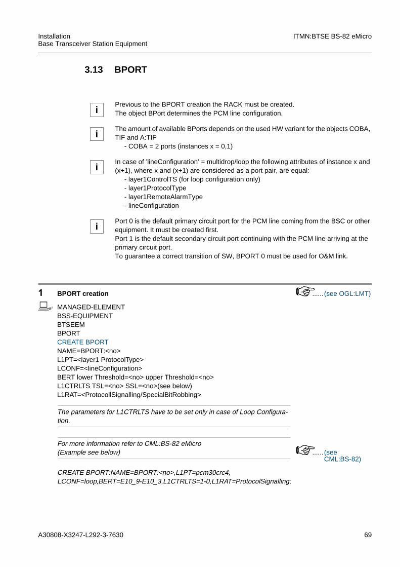
A30808-X3247-L292-3-7630 69
InstallationBase Transceiver Station Equipment
ITMN:BTSE BS-82 eMicro
3.13 BPORT
1 BPORT creation ...... (see OGL:LMT)
b MANAGED-ELEMENTBSS-EQUIPMENTBTSEEMBPORTCREATE BPORTNAME=BPORT:<no>L1PT=<layer1 ProtocolType>LCONF=<lineConfiguration>BERT lower Threshold=<no> upper Threshold=<no>L1CTRLTS TSL=<no> SSL=<no>(see below)L1RAT=<ProtocollSignalling/SpecialBitRobbing>
The parameters for L1CTRLTS have to be set only in case of Loop Configura-tion.
For more information refer to CML:BS-82 eMicro(Example see below) ...... (see
CML:BS-82)
CREATE BPORT:NAME=BPORT:<no>,L1PT=pcm30crc4,LCONF=loop,BERT=E10_9-E10_3,L1CTRLTS=1-0,L1RAT=ProtocolSignalling;
iPrevious to the BPORT creation the RACK must be created.The object BPort determines the PCM line configuration.
iThe amount of available BPorts depends on the used HW variant for the objects COBA,TIF and A:TIF
- COBA = 2 ports (instances x = 0,1)
iIn case of ’lineConfiguration’ = multidrop/loop the following attributes of instance x and(x+1), where x and (x+1) are considered as a port pair, are equal:
- layer1ControlTS (for loop configuration only)- layer1ProtocolType- layer1RemoteAlarmType- lineConfiguration
iPort 0 is the default primary circuit port for the PCM line coming from the BSC or otherequipment. It must be created first.Port 1 is the default secondary circuit port continuing with the PCM line arriving at theprimary circuit port.To guarantee a correct transition of SW, BPORT 0 must be used for O&M link.
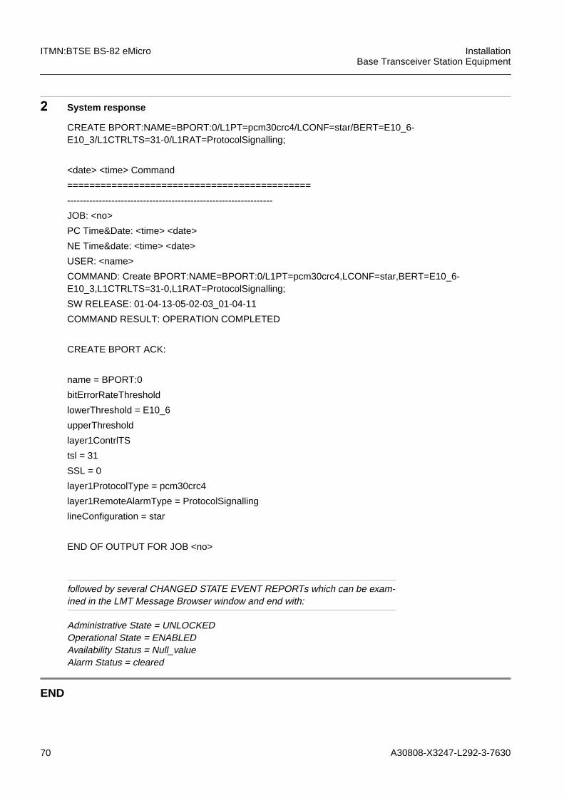
70 A30808-X3247-L292-3-7630
ITMN:BTSE BS-82 eMicro InstallationBase Transceiver Station Equipment
2 System response
followed by several CHANGED STATE EVENT REPORTs which can be exam-ined in the LMT Message Browser window and end with:
Administrative State = UNLOCKEDOperational State = ENABLEDAvailability Status = Null_valueAlarm Status = cleared
END
CREATE BPORT:NAME=BPORT:0/L1PT=pcm30crc4/LCONF=star/BERT=E10_6-E10_3/L1CTRLTS=31-0/L1RAT=ProtocolSignalling;
<date> <time> Command
============================================
-----------------------------------------------------------------
JOB: <no>
PC Time&Date: <time> <date>
NE Time&date: <time> <date>
USER: <name>
COMMAND: Create BPORT:NAME=BPORT:0/L1PT=pcm30crc4,LCONF=star,BERT=E10_6-E10_3,L1CTRLTS=31-0,L1RAT=ProtocolSignalling;
SW RELEASE: 01-04-13-05-02-03_01-04-11
COMMAND RESULT: OPERATION COMPLETED
CREATE BPORT ACK:
name = BPORT:0
bitErrorRateThreshold
lowerThreshold = E10_6
upperThreshold
layer1ContrlTS
tsl = 31
SSL = 0
layer1ProtocolType = pcm30crc4
layer1RemoteAlarmType = ProtocolSignalling
lineConfiguration = star
END OF OUTPUT FOR JOB <no>
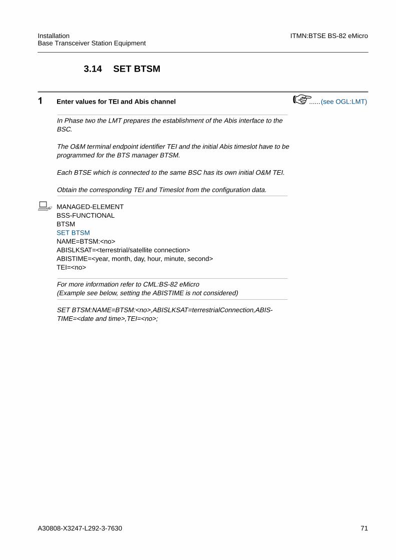
A30808-X3247-L292-3-7630 71
InstallationBase Transceiver Station Equipment
ITMN:BTSE BS-82 eMicro
3.14 SET BTSM
1 Enter values for TEI and Abis channel ...... (see OGL:LMT)
In Phase two the LMT prepares the establishment of the Abis interface to theBSC.
The O&M terminal endpoint identifier TEI and the initial Abis timeslot have to beprogrammed for the BTS manager BTSM.
Each BTSE which is connected to the same BSC has its own initial O&M TEI.
Obtain the corresponding TEI and Timeslot from the configuration data.
b MANAGED-ELEMENTBSS-FUNCTIONALBTSMSET BTSMNAME=BTSM:<no>ABISLKSAT=<terrestrial/satellite connection>ABISTIME=<year, month, day, hour, minute, second>TEI=<no>
For more information refer to CML:BS-82 eMicro(Example see below, setting the ABISTIME is not considered)
SET BTSM:NAME=BTSM:<no>,ABISLKSAT=terrestrialConnection,ABIS-TIME=<date and time>,TEI=<no>;

72 A30808-X3247-L292-3-7630
ITMN:BTSE BS-82 eMicro InstallationBase Transceiver Station Equipment
2 System response
followed by several CHANGED STATE EVENT REPORTs which can be exam-ined in the LMT Message Browser window
END
SET BTSM:NAME=BTSM:0/ABISLKSAT=terrestrialConnection/TEI=1;
<date> <time> Command
============================================
-----------------------------------------------------------------
JOB: <no>
PC Time&Date: <time> <date>
NE Time&date: <time> <date>
USER: <name>
COMMAND: SET BTSM:NAME=BTSM:0,ABISLKSAT=terrestrialConnection,TEI=1;
SW RELEASE: 01-04-13-05-02-03_01-04-11
COMMAND RESULT: OPERATION COMPLETED
SET BTSM ACK:
name = BTSM:0
tei = 1
sAbisLinkSatellite = terrestrialConnection
END OF OUTPUT FOR JOB <no>
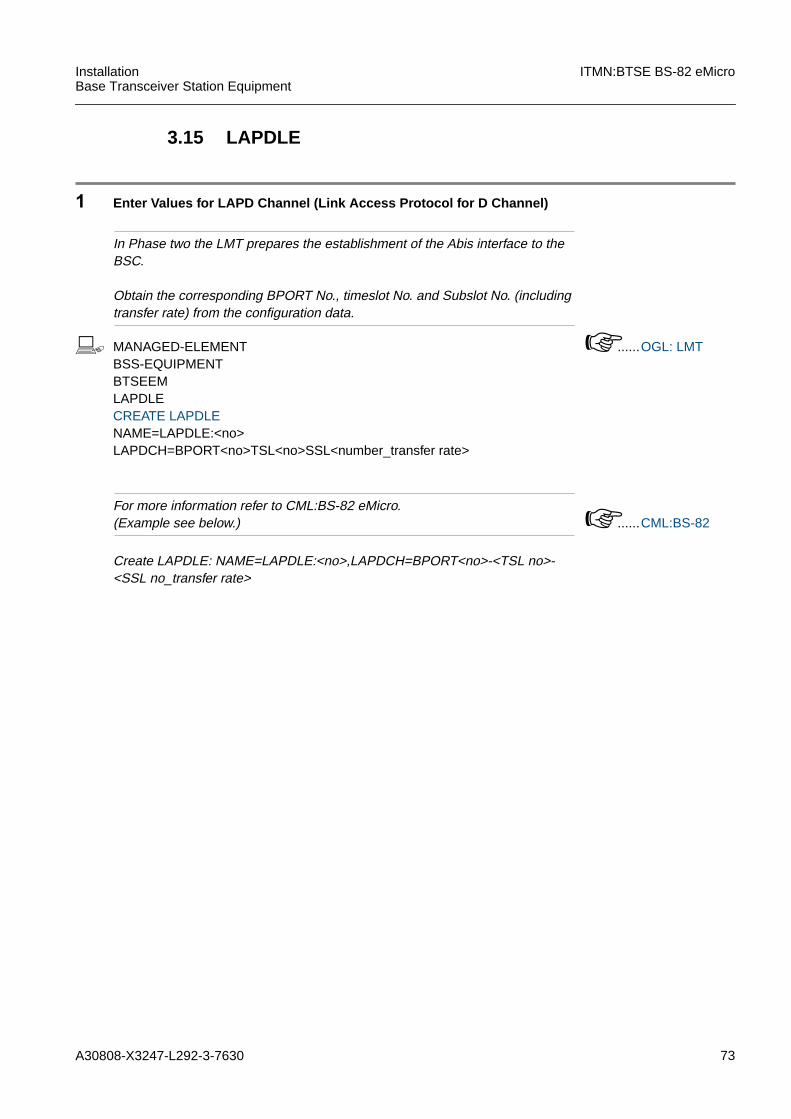
A30808-X3247-L292-3-7630 73
InstallationBase Transceiver Station Equipment
ITMN:BTSE BS-82 eMicro
3.15 LAPDLE
1 Enter Values for LAPD Channel (Link Access Protocol for D Channel)
In Phase two the LMT prepares the establishment of the Abis interface to theBSC.
Obtain the corresponding BPORT No., timeslot No. and Subslot No. (includingtransfer rate) from the configuration data.
b MANAGED-ELEMENTBSS-EQUIPMENTBTSEEMLAPDLECREATE LAPDLENAME=LAPDLE:<no>LAPDCH=BPORT<no>TSL<no>SSL<number_transfer rate>
......OGL: LMT
For more information refer to CML:BS-82 eMicro.(Example see below.) ......CML:BS-82
Create LAPDLE: NAME=LAPDLE:<no>,LAPDCH=BPORT<no>-<TSL no>-<SSL no_transfer rate>
74 A30808-X3247-L292-3-7630
ITMN:BTSE BS-82 eMicro InstallationBase Transceiver Station Equipment
2 System Response
Several CHANGED STATE EVENT REPORTs will follow. They can be examinedin the LMT Browser window.
END
Create LAPDLE:NAME=LAPDLE:<no>,LAPDCH=BPORT<no>-<TSL no>-<SSL>
<time> <date> Command
============================================
JOB: <no>
PC Time&Date: <time> <date>
NE Time&Date: <time> <date>
USER: <user>
COMMAND: Create LAPDLE:NAME=LAPDLE:<no>,LAPDCH=BPORT<no>-<TSL no>-<SSL>
SW RELEASE: <no>
COMMAND RESULT: <command result>
CREATE LAPDLE ACK:
name=LAPDLE:<no>
lapdChannel
BPORT = <BPORT>
TSL = <no>
SSL = <ssl>
END OF OUTPUT FOR JOB <no>
A30808-X3247-L292-3-7630 75
InstallationBase Transceiver Station Equipment
ITMN:BTSE BS-82 eMicro
3.16 Check the State of All Modules
1 Check the state of all modules ...... (see OGL:LMT)
All images have been loaded. This is confirmed by the state event report:
Administrative State = UNLOCKEDOperational State = ENABLEDfor all successfully created objects.
This can be verified via logfile in browser mode or via LMT commands with:
MANAGED-ELEMENTBSS-EQUIPMENTBTSEEMRACK<module>GET <module>NAME=RACK:<no>/<module>:<no>REQATTL=AST&OST
All red LEDs (except the PA LED on the CU) have been switched off.If no Abis is connected the corresponding LED on the COBA/COSA is red.
The files can be viewed in the Message Browser.
END

76 A30808-X3247-L292-3-7630
ITMN:BTSE BS-82 eMicro InstallationBase Transceiver Station Equipment
3.17 Replacing of Failed HW
1 Module Test
After replacing a failed HW unit it is necessary to enable this new HW unit viatest or delete/create command before starting any other activities (e. g. down-load or activate SW) because the PID of a new module is only updated after testor create and it is necessary during download to have the actual PID of all mod-ules stored on COBAM.
In case of unlocking BTSM this unlocking causes a full BTS alignment.In case off issuing BTSE configuration commands during an alignment a newalignment will be started.
END

A30808-X3247-L292-3-7630 77
InstallationBase Transceiver Station Equipment
ITMN:BTSE BS-82 eMicro
3.18 External Alarm Check
The Operator Alarm Interface has to be checked. All the alarms should have been con-figured previously in the ENVABTSE object (see PROC: Create the Alarm Configuration(ENVABTSE))
For every couple of alarm terminals on the alarm connection terminal (see IMN:BTSE)alternatively close/open the contact and check on the LMT the corresponding alarmmessage. If the alarm is configured high, an alarm start message will be displayed first,if it is configured low, an alarm cease message will be displayed first.
iImportant:The test should not be done before the completion of the alarm configuration(ENVABTSE).

78 A30808-X3247-L292-3-7630
ITMN:BTSE BS-82 eMicro InstallationBase Transceiver Station Equipment
3.19 Generating BTS Backup Files
Via the backup files (script files) a quick reconfiguration of the BTSE is possible (for ex-ample necessary after a COBA replacement).
The backup files are generated via the Backup BTS Tool: the configuration data of theBTSE are at first loaded to the LMT PC and are then converted to script files. Thosescript files are written to the LMT subdirectory “BKBTS\ENHMICRO”. They should becopied and stored on site.
1 Start the Backup BTS Tool
b Start the Backup BTS tool via the WINDOWS Start menu
The “BACKUPBTS” window opens.
2 Perform the Command “Get HW Configuration”
b Click on the button “Get HW Configuration”.
Several reports are displayed in the “BACKUPBTS” window. After a few min-utes, the following message is displayed:
THE SCRIPT WAS DONE SUCCESSFULLY
iStarting with BR7.0, a second LMT version is available: the new LMT Evolution. Forgenerating BTS backup files with the LMT Evolution, refer to the operator guidelinesOGL:LMT Evolution.
iWhen reconfiguring in phase 2 a BS-82 using command files got from Backup Script(Delete all HW, Create all HW), it may happen that the BS-82 switch directly to zero con-figuration after an alarm on one of the AC/DC module.To avoid this, the backup script containing ACDCP and BATTERY modules creationshould be modified before execution.A sleep time has to be inserted between each ACDCP and BATTERY creation com-mand (sleep:time=15;) in the script file “scrpt5em.lmt” got from the LMT backup tool.This file is a CLI text file and can be edited.
(Start:\Programs\LMT...\Backup BTS) or click on the “Backup BTS” iconin the “LMT Control Center” window.
A30808-X3247-L292-3-7630 79
InstallationBase Transceiver Station Equipment
ITMN:BTSE BS-82 eMicro
3 Convert the Configuration Data to Script Files
b Click on the button “Convert to Script File”.
The following message is displayed in the “BACKUPBTS” window:
THE CONVERSION WAS DONE SUCCESSFULLY!THE SCRIPT WAS DONE SUCCESSFULLY
The backup BTS tool writes the following files into the BKBTS\ENHMICRO sub-directory:SCRIPT1.LMTSCRIPT2.LMTSCRIPT3.LMT(...)
4 Copy the Script Files to Disk
b Copy the script files from [Drive]:\[LMT_Root]\BKBTS\ENHMICRO to some stor-age media and keep it at the site in case a backup copy of the BTSE configura-tion is needed.
END
80 A30808-X3247-L292-3-7630
ITMN:BTSE BS-82 eMicro InstallationBase Transceiver Station Equipment
3.20 Remote Inventory
The function “Remote Inventory” of the Siemens Basestation System performs electron-ic, non volatile storing of the complete, individual product identification data (PID) ofeach inventory object.
Modules that have its inventory data on board are called ob_RIUs (on-board RemoteInventory Units). The PID of this ob_RIUs is automatically loaded to the Inventory DataFile (IDF).
In order to include inventory data of objects without a non volatile storage (e. g. frames,racks, OEM components), the data of these so called nob_RIUs (not on-board RemoteInventory Units) are entered into an inventory data table (IDT) via the LMT and the off-line tool ”IDF-Editor”. As a nob_RIU file (NOB) these data are stored on the COBA.
The complete Remote Inventory Data is delivered with each Rack on a disk. The filename is composed of the serial number of the Rack ( “/” replaced by “_“) and the exten-sion “IDF”, for example: “CN+_JD100001.IDF”. The data of the nob_RIUs has to be at-tached to the automatically created PID of the ob_RIUs.
1 Check the Settings of the BTSE
The “equipmentPosition” (EQUPOS) and the “salesUniqueName” (SALUNAME)are absolutely necessary for the “Remote Inventory” feature. These attributeswere set previously during the procedure “Setting the BTSE Attributes” and maybe checked for correctness.
......(see 3.14)
Also the Type of BTSE (TYPRACK) is mandatory and was set during the proce-dure “Rack”
......(see 3.3)
iStarting with BR7.0, a second LMT version is available: the new LMT Evolution. Forperforming this procedure with the LMT Evolution, refer to the operator guidelinesOGL:LMT Evolution and OGL:IDF Evolution.
iFor Remote Inventory the BR5.0 LMT or higher is mandatory!
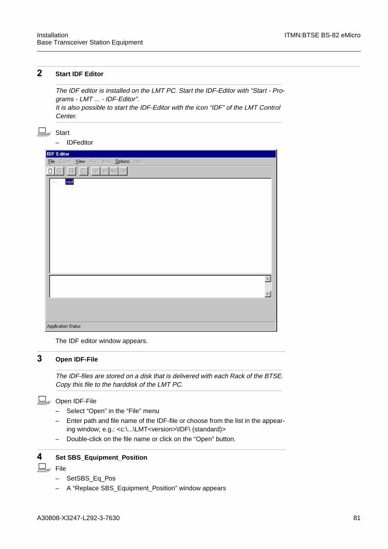
A30808-X3247-L292-3-7630 81
InstallationBase Transceiver Station Equipment
ITMN:BTSE BS-82 eMicro
2 Start IDF Editor
The IDF editor is installed on the LMT PC. Start the IDF-Editor with “Start - Pro-grams - LMT ... - IDF-Editor”.It is also possible to start the IDF-Editor with the icon “IDF” of the LMT ControlCenter.
b Start
– IDFeditor
The IDF editor window appears.
3 Open IDF-File
The IDF-files are stored on a disk that is delivered with each Rack of the BTSE.Copy this file to the harddisk of the LMT PC.
b Open IDF-File
– Select “Open” in the “File” menu
– Enter path and file name of the IDF-file or choose from the list in the appear-ing window; e.g.: <c:\...\LMT<version>\IDF\ (standard)>
– Double-click on the file name or click on the “Open” button.
4 Set SBS_Equipment_Position
b File
– SetSBS_Eq_Pos
– A “Replace SBS_Equipment_Position” window appears
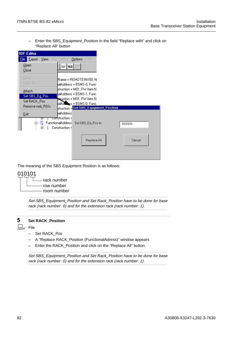
82 A30808-X3247-L292-3-7630
ITMN:BTSE BS-82 eMicro InstallationBase Transceiver Station Equipment
– Enter the SBS_Equipment_Position in the field “Replace with” and click on“Replace All” button
Set SBS_Equipment_Position and Set Rack_Position have to be done for baserack (rack number: 0) and for the extension rack (rack number: 1).
5 Set RACK_Position
b File
– Set RACK_Pos
– A “Replace RACK_Position (FunctionalAdress)” window appears
– Enter the RACK_Position and click on the “Replace All” button.
Set SBS_Equipment_Position and Set Rack_Position have to be done for baserack (rack number: 0) and for the extension rack (rack number: 1).
010101rack numberrow numberroom number
The meaning of the SBS Equipment Position is as follows:
010101
A30808-X3247-L292-3-7630 83
InstallationBase Transceiver Station Equipment
ITMN:BTSE BS-82 eMicro
6 Check nob_RIU Data
Are the data of the nob_RIU modules/elements ok? Y h...8N h...7
For a complete list of all nob_RIUs for BS-82 refer to MMN:BTSE BS-82 ...... (seeMMN:BTSEBS-82)
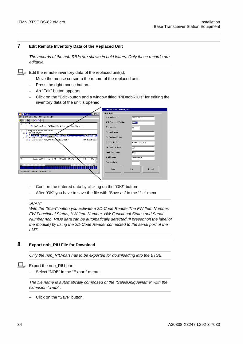
84 A30808-X3247-L292-3-7630
ITMN:BTSE BS-82 eMicro InstallationBase Transceiver Station Equipment
7 Edit Remote Inventory Data of the Replaced Unit
The records of the nob-RIUs are shown in bold letters. Only these records areeditable.
b Edit the remote inventory data of the replaced unit(s):
– Move the mouse cursor to the record of the replaced unit.
– Press the right mouse button.
– An “Edit”-button appears
– Click on the “Edit”-button and a window titled “PIDnobRIU’s” for editing theinventory data of the unit is opened
– Confirm the entered data by clicking on the “OK!”-button
– After “OK” you have to save the file with “Save as” in the “file” menu
SCAN:With the “Scan” button you activate a 2D-Code Reader.The FW Item Number,FW Functional Status, HW Item Number, HW Functional Status and SerialNumber nob_RIUs data can be automatically detected (if present on the label ofthe module) by using the 2D-Code Reader connected to the serial port of theLMT.
8 Export nob_RIU File for Download
Only the nob_RIU-part has to be exported for downloading into the BTSE.
b Export the nob_RIU-part:
– Select “NOB” in the “Export” menu.
The file name is automatically composed of the “SalesUniqueName” with theextension “.nob ” .
– Click on the “Save” button.

A30808-X3247-L292-3-7630 85
InstallationBase Transceiver Station Equipment
ITMN:BTSE BS-82 eMicro
A question window opens: Create Nob RIUs file for Download?
– Click on the “Yes” button.
A window opens which displays the destination path of the NOB-file, for exam-ple:C:\...\LMT<version>\IDF\DNLOAD\BTS_NRIU.nob
– Click on the “OK” button.
9 Upload IDT-File from BTSE
Change to the LMT application!
b MANAGED-ELEMENTBSS-EQUIPMENTBTSEREMINVUPLLIDF REMINV(DESTDIR=<path>)(FILE=<file name>)OVERWRITE=YES
The values DESTDIR and FILE are optional. If no special path or file name isentered, the file is uploaded to the default directory of the IDF editor.If the value OVERWRITE=YES is selected, a former version of an uploaded IDT-file will be overwritten.
UPLLIDF REMINV: NAME=REMINV<no>, (DESTDIR=”<for example:C:...\LMT<version>\Idf\Upload”>,FILE=<for example: “btse.idt”>,) OVER-WRITE= YES;
10 System Response
<date> <time> Command
============================================
JOB: <no>
PC Time&Date: <time>/<date>
COMMAND: UPLLIDF REMINV:NAME=REMINV:<no>,OVERWRITE=Yes;
COMMAND RESULT: OPERATION COMPLETED
Uploading File <for example: BTSE.IDT>:
To: <for example: BTSE.IDT>
On Directory:<for example:...\Idf\Upload>
86 A30808-X3247-L292-3-7630
ITMN:BTSE BS-82 eMicro InstallationBase Transceiver Station Equipment
11 Open IDT-File
b Open the IDT-file:
– Change to the IDF Editor.
– Select “Open” in the “File” menu.
– Select the uploaded file from the list in the appearing window; e.g.:<C:\...\LMT<version>\IDF\UPLOAD\BTSE.idt”>.
– Click on the “Open” button.
12 Attach nob_RIU File to Actually Loaded File
b Attach nob_RIU file to the actually loaded File:
– Select “Attach” in the “File” menu.
– Select the exported nob_RIU file from the list in the appearing window (thedestination path was given during step 8); e.g.: <C:\...\LMT<ver-sion>\IDF\DNLOAD\BTS_NRIU.nob>.
– Click on the “Open” button.
An “ATTENTION” window opens.
– Click on the “OK” button.
END OF OUTPUT FOR JOB <no>
<date> <time> Command
============================================
JOB: <no>
PC Time&Date: <time>/<date>
COMMAND: UPLLIDF REMINV:NAME=REMINV:<no>,OVERWRITE=Yes;
COMMAND RESULT: OPERATION COMPLETED
Uploading End: File <for example: BTSE.IDT> Transfer Completed
END OF OUTPUT FOR JOB <no>
A30808-X3247-L292-3-7630 87
InstallationBase Transceiver Station Equipment
ITMN:BTSE BS-82 eMicro
13 Remove Redundant nob_RIU Files
b Remove redundant nob_RIU files:
– Select “Remove nob_RIU’s File” in the “File” menu.
An “Attention” window opens.
– Click on the “Yes” button to confirm the deletion of all redundant nob_RIUs.
Another “Attention” window opens.
– Click on the “Yes” button.
14 Export IDF-File for Backup
b Export IDF-file:
– Select “IDF” in the “Export” menu.
– Select the destination path in the appearing window, preferably “A:\”.
The file name is automatically composed of the “SalesUniqueName” with theextension “.idf ” .
– Click on the “Save” button.
– Put the disk with the backup file of the inventory data to the site specific doc-umentation.
15 Export Nob_RIU File
Only the nob_RIU-part has to be exported for downloading into the BTSE.
b Export the nob_RIU-part:
– Select “NOB” in the “Export” menu.
The file name is automatically composed of the “SalesUniqueName” with theextension “.nob ” .
– Click on the “Save” button.
A question window opens: Create Nob RIUs file for Download?
– Click on the “Yes” button.
A window opens which displays the destination path of the NOB-file, for exam-ple:C:\...\LMT<version>\IDF\DNLOAD\BTS_NRIU.nob
– Click on the “OK” button.
88 A30808-X3247-L292-3-7630
ITMN:BTSE BS-82 eMicro InstallationBase Transceiver Station Equipment
16 Download nob_RIU File to BTSE
Change to the LMT application!
b MANAGED-ELEMENTBSS-EQUIPMENTBTSEREMINVDNLIDFD REMINVSRCDIR=<source directory>
SRCDIR: enter the source directory in which the exported NOB-file was saved,for example C:\...\LMT<version>\IDF\DNLOAD.
DNLIDFD:SRCDIR=”C:\...\LMT<version>\IDF\DNLOAD”;
17 System response
END
============================================
PC Time&Date: <time> <date>
COMMAND: DNLIDF REMINV:NAME=REMINV:0,SRCDIR=”C:\IDFeditor”;
COMMAND RESULT: OPERATION COMPLETED
Downloading File: <for example BTS_NRIU>
100% of packets transferred
On Directory: C:\SIEMENS\LMT<version>\IDF\DNLOAD (standard)
============================================
PC Time&Date: <time> <date>
COMMAND: DNLIDF REMINV:NAME=REMINV:0,SRCDIR=”C:\SIEMENS\LMT<version>\IDF\DN-LOAD”;
COMMAND RESULT: OPERATION COMPLETED
Download End: File BTS_NRIU Transfer Completed

A30808-X3247-L292-3-7630 89
InstallationBase Transceiver Station Equipment
ITMN:BTSE BS-82 eMicro
3.21 Switch to Phase 3
1 Manual switch to phase 3
For forced switchover to Phase 3 a special command may be entered at theLMT.
b MANAGED-ELEMENTBSS-FUNCTIONALBTSMCONNBSC BTSMNAME=BTSM:0
...... (see OGL:LMT)
CONNBSC BTSM:NAME=BTSM:0;
2 System response
The session is closed, processing is aborted.
3 Logon ...... (see OGL:LMT)
b LogonUserID: <user>Password: <password>Connect
The BTSE is now in phase 3The BTSE is now connected to the BSC
The LED indication on the COBAM changes to
The LED indication on the COBAM changes to
iStarting with BR7.0, a second LMT version is available: the new LMT Evolution. Forswitching the phases with the LMT Evolution, refer to the operator guidelinesOGL:LMT Evolution.
ACT fl(G) RCOBA
FLOC fl(G) HMO
ABIS 1 ABIS 2
OK fl(G) fl(G) SW
RES PA
90 A30808-X3247-L292-3-7630
ITMN:BTSE BS-82 eMicro InstallationBase Transceiver Station Equipment
END
If you have problems switching over to Phase 3:
In case of problems with the switchover to Phase 3, please refer to the following checklist. Here the minimalBTSE configuration is described with the preconditions for a successful switchover to Phase 3:
COBA-0 = unlocked.enabled
– COBA-0 is always created and enabled automatically.Here the Administrative State (AST*) is relevant.
Minimal parameters of RACK-0: available
– This means that “TypeOfBTSE” (TYPRACK) must be set first beforeany HMO can be created.
LAPDLE-0 = created
Minimal parameters of LAPDLE-0: available
– This means that the LAPD channel (LAPDCH) must be defined.
Accuracy of CCLK >= medium (at least)
– The current CCLK accuracy can be determined by performing theLMT command Get COBA ---> REQATTL ---> CCLKACC.
Minimal parameters of BTSM: available
– This means that the TEI must be defined.
Minimal parameters of BPORT-0: available
– This means that the “L1ControlTimeSlot” (L1CTRLTS) and“LoopConfiguration” (LCONF) must be defined.
*) For more information on the Administrative State (AST), please refer to MMN:BTSE BS-82 eMicro
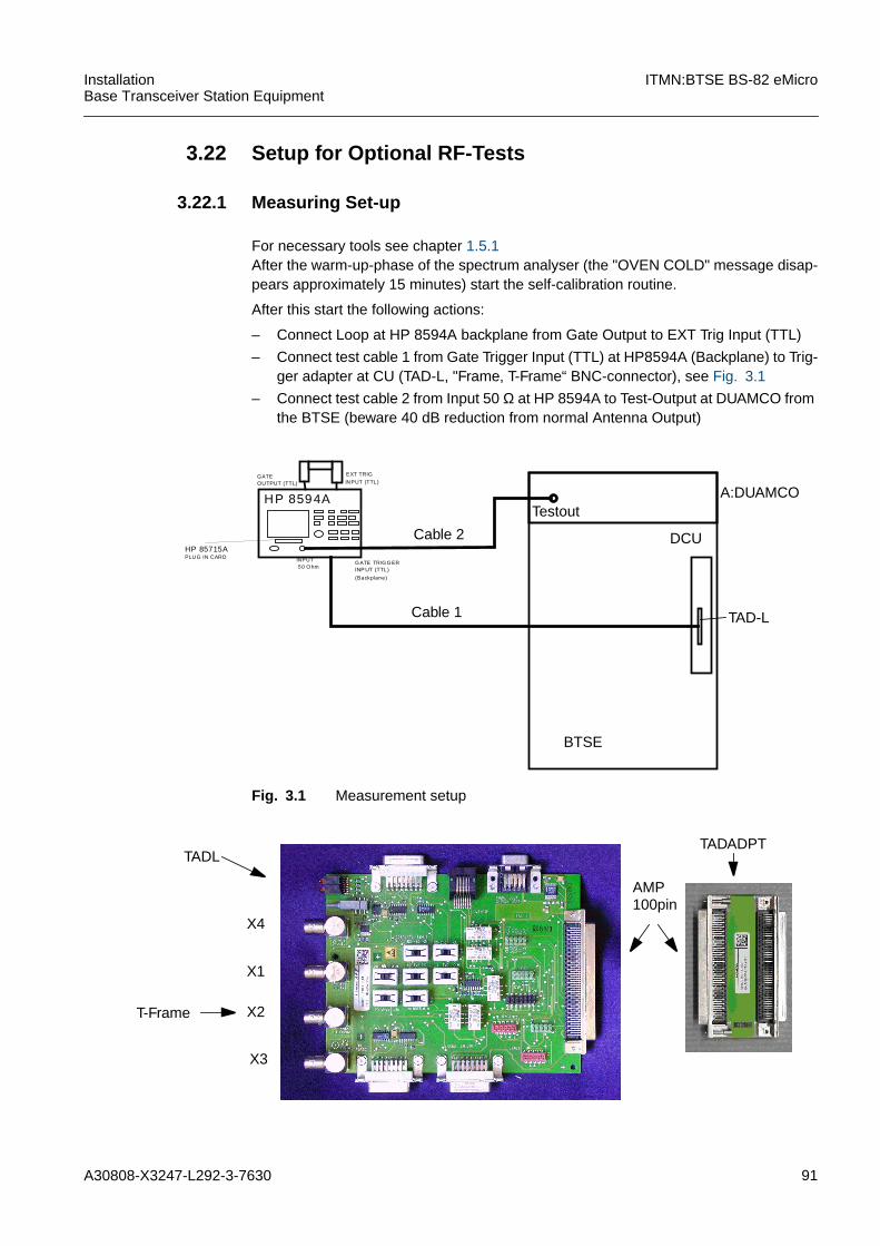
A30808-X3247-L292-3-7630 91
InstallationBase Transceiver Station Equipment
ITMN:BTSE BS-82 eMicro
3.22 Setup for Optional RF-Tests
3.22.1 Measuring Set-up
For necessary tools see chapter 1.5.1After the warm-up-phase of the spectrum analyser (the "OVEN COLD" message disap-pears approximately 15 minutes) start the self-calibration routine.
After this start the following actions:
– Connect Loop at HP 8594A backplane from Gate Output to EXT Trig Input (TTL)
– Connect test cable 1 from Gate Trigger Input (TTL) at HP8594A (Backplane) to Trig-ger adapter at CU (TAD-L, "Frame, T-Frame“ BNC-connector), see Fig. 3.1
– Connect test cable 2 from Input 50 Ω at HP 8594A to Test-Output at DUAMCO fromthe BTSE (beware 40 dB reduction from normal Antenna Output)
Fig. 3.1 Measurement setup
HP 8594A
INPUT50 O hm
G ATE TRIG G ERINP UT (TTL)
(Backplane)
HP 85715A
GATE EXT TRIG
INPUT (TTL)OUTPUT (TTL)
PLU G IN CARD
TAD-L
DCU
Cable 1
Cable 2
TestoutA:DUAMCO
BTSE
X4
X3
X2
X1
T-Frame
AMP100pin
TADLTADADPT
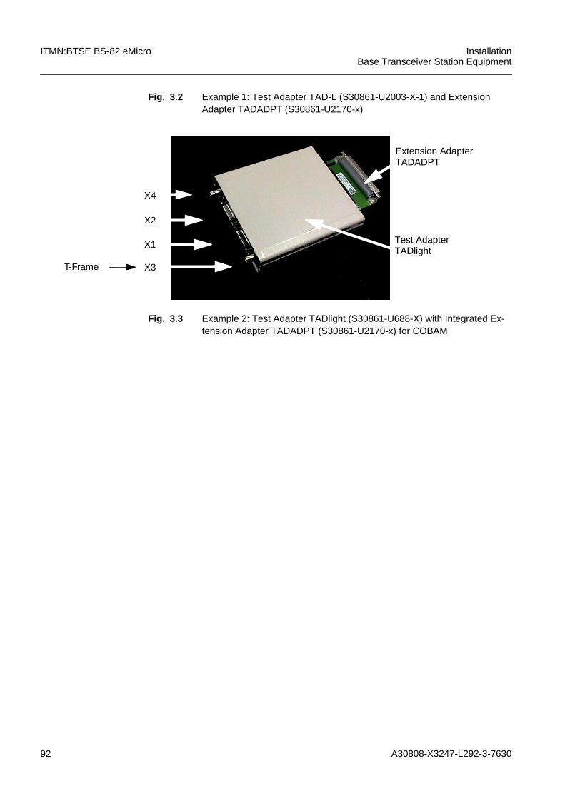
92 A30808-X3247-L292-3-7630
ITMN:BTSE BS-82 eMicro InstallationBase Transceiver Station Equipment
Fig. 3.2 Example 1: Test Adapter TAD-L (S30861-U2003-X-1) and ExtensionAdapter TADADPT (S30861-U2170-x)
Fig. 3.3 Example 2: Test Adapter TADlight (S30861-U688-X) with Integrated Ex-tension Adapter TADADPT (S30861-U2170-x) for COBAM
Extension AdapterTADADPT
Test AdapterTADlight
X4
X2
X1
X3T-Frame
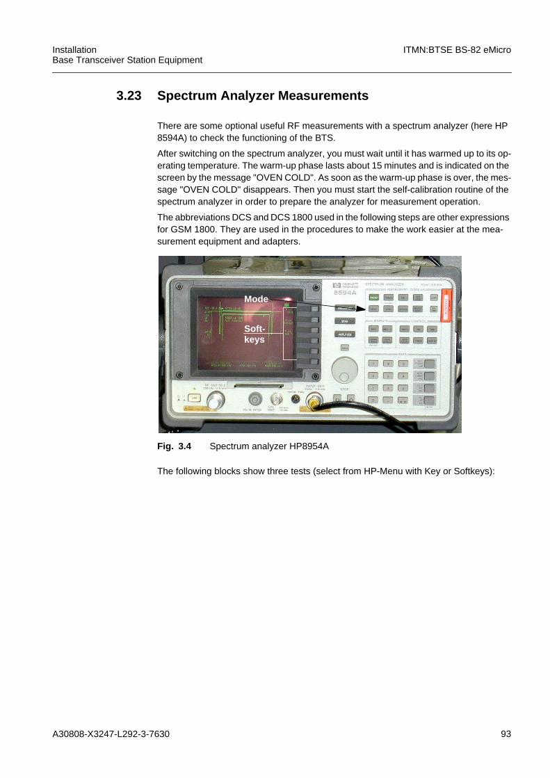
A30808-X3247-L292-3-7630 93
InstallationBase Transceiver Station Equipment
ITMN:BTSE BS-82 eMicro
3.23 Spectrum Analyzer Measurements
There are some optional useful RF measurements with a spectrum analyzer (here HP8594A) to check the functioning of the BTS.
After switching on the spectrum analyzer, you must wait until it has warmed up to its op-erating temperature. The warm-up phase lasts about 15 minutes and is indicated on thescreen by the message "OVEN COLD". As soon as the warm-up phase is over, the mes-sage "OVEN COLD" disappears. Then you must start the self-calibration routine of thespectrum analyzer in order to prepare the analyzer for measurement operation.
The abbreviations DCS and DCS 1800 used in the following steps are other expressionsfor GSM 1800. They are used in the procedures to make the work easier at the mea-surement equipment and adapters.
Fig. 3.4 Spectrum analyzer HP8954A
The following blocks show three tests (select from HP-Menu with Key or Softkeys):
Soft-keys
Mode
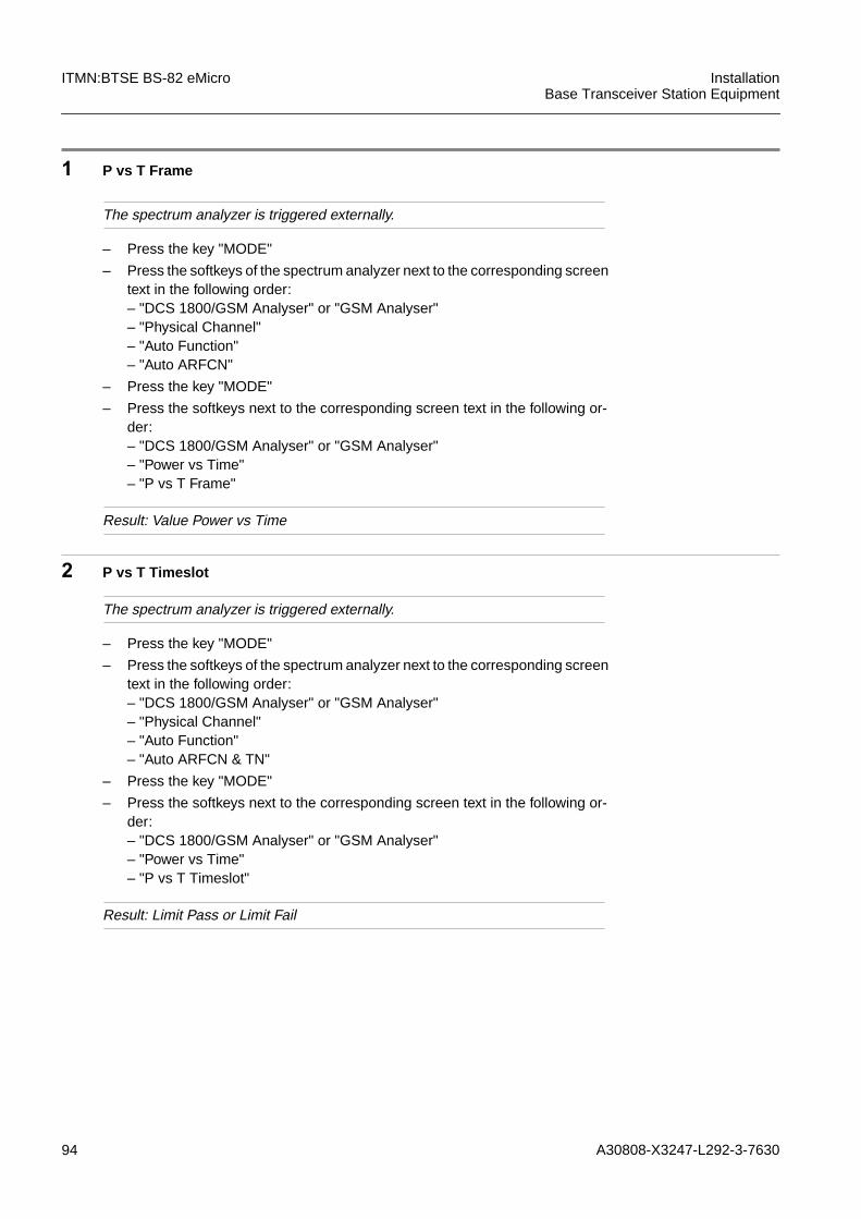
94 A30808-X3247-L292-3-7630
ITMN:BTSE BS-82 eMicro InstallationBase Transceiver Station Equipment
1 P vs T Frame
The spectrum analyzer is triggered externally.
– Press the key "MODE"
– Press the softkeys of the spectrum analyzer next to the corresponding screentext in the following order:– "DCS 1800/GSM Analyser" or "GSM Analyser"– "Physical Channel"– "Auto Function"– "Auto ARFCN"
– Press the key "MODE"
– Press the softkeys next to the corresponding screen text in the following or-der:– "DCS 1800/GSM Analyser" or "GSM Analyser"– "Power vs Time"– "P vs T Frame"
Result: Value Power vs Time
2 P vs T Timeslot
The spectrum analyzer is triggered externally.
– Press the key "MODE"
– Press the softkeys of the spectrum analyzer next to the corresponding screentext in the following order:– "DCS 1800/GSM Analyser" or "GSM Analyser"– "Physical Channel"– "Auto Function"– "Auto ARFCN & TN"
– Press the key "MODE"
– Press the softkeys next to the corresponding screen text in the following or-der:– "DCS 1800/GSM Analyser" or "GSM Analyser"– "Power vs Time"– "P vs T Timeslot"
Result: Limit Pass or Limit Fail
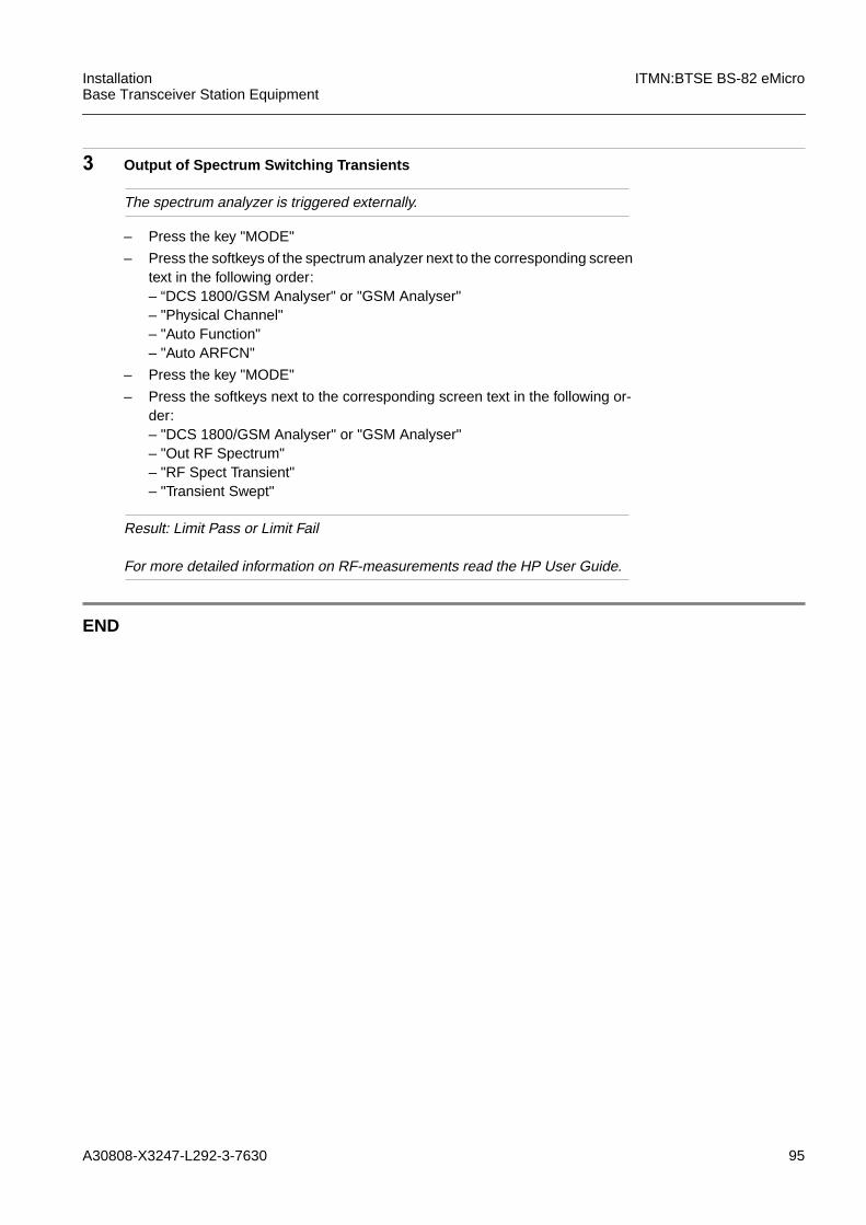
A30808-X3247-L292-3-7630 95
InstallationBase Transceiver Station Equipment
ITMN:BTSE BS-82 eMicro
3 Output of Spectrum Switching Transients
The spectrum analyzer is triggered externally.
– Press the key "MODE"
– Press the softkeys of the spectrum analyzer next to the corresponding screentext in the following order:– “DCS 1800/GSM Analyser" or "GSM Analyser"– "Physical Channel"– "Auto Function"– "Auto ARFCN"
– Press the key "MODE"
– Press the softkeys next to the corresponding screen text in the following or-der:– "DCS 1800/GSM Analyser" or "GSM Analyser"– "Out RF Spectrum"– "RF Spect Transient"– "Transient Swept"
Result: Limit Pass or Limit Fail
For more detailed information on RF-measurements read the HP User Guide.
END
96 A30808-X3247-L292-3-7630
ITMN:BTSE BS-82 eMicro InstallationBase Transceiver Station Equipment
3.24 VSWR Test
For VSWR test, disconnect the antenna cable! After disconnection of all antenna cables,the respective VSWR LEDs on the CUs should go on.
3.25 RFA-Confirmation: Unit ATMN
Finally the site must be accepted by the customer. On customer request, the HW func-tionality of the Network Entity has to be verified by following the steps described in therelevant Unit-ATMN prior to this acceptance.
A30808-X3247-L292-3-7630 97
InstallationBase Transceiver Station Equipment
ITMN:BTSE BS-82 eMicroTABIN
4 Tables, lists and figures (TAB)
TABIN

98 A30808-X3247-L292-3-7630
ITMN:BTSE BS-82 eMicro InstallationBase Transceiver Station Equipment
4.1 Frequency/Channel Conversion Table
For a frequency/channel conversion table, please refer to the "Technical Description(TED:BSS) Common”.

A30808-X3247-L292-3-7630 99
InstallationBase Transceiver Station Equipment
ITMN:BTSE BS-82 eMicro
5 Appendix
5.1 Examples of Configuration
5.1.1 Types of DCU
There are different types of DCU available, (see HW:BTSE Modules, DCU)
5.1.1.1 DCUDUXxThe DCUDUXx is used for full on air combining. Each DCUDUX includes duplexers tocombine uplink and downlink for each carrier (=HMO CU) to one antenna. In the RX patha LNA amplifies the RF signal.
Fig. 5.1 DCUDUXx (x = frequency denotation)
5.1.1.2 DCURGYou see a block diagram of DCURG, full combining on air configuration for E-GSM withexternal dupexer, only RF signal flow is shown.
M:AMCO2x
M:AMCO2x
M:PWRST-Mx
M:PWRSTMx
M:RXAx
M:TXAx
M:RXAx
M:TXAx
M:PSUM (DC/DC Converter)
Heat Sink
SIP-RO
SIP-ROM
RXFIL
TXFIL
RXFIL
TXFIL
M:COBAM
M:COBAM
CC
CC

100 A30808-X3247-L292-3-7630
ITMN:BTSE BS-82 eMicro InstallationBase Transceiver Station Equipment
Fig. 5.2 DCURG
5.1.1.3 DCULGxThe DCULGx is used for hybrid combining together with A:DUAMCOM. The DCULGxdoes not contain duplexers, duplexing is done by A:DUAMCOM. The RX signal is am-plified by A:DUAMCOM. So the LNA unit in DCULGx is a splitter that divides the RX sig-nal between the two RXA boards for diversity.
M:AMCO2R
M:AMCO2R
M:PWRST-MR
M:PWRSTMR
M:RXAG
M:TXAG
M:RXAG
M:TXAG
M:PSUM (DC/DC Converter)
Heat Sink
M:SIP-ROG
M:SIP-ROG
M:COBAM
M:COBAM
CC
CC
toA:DUXMEG

A30808-X3247-L292-3-7630 101
InstallationBase Transceiver Station Equipment
ITMN:BTSE BS-82 eMicro
Fig. 5.3 DCULGx
5.1.2 Combining on air with DCUDUX
Combining on air is done with DCUDUX and INTENNA or external antenna.
iThis participates an example
M:AMCO2LGx
M:AMCO2LGx
M:PWRST-Mx
M:PWRSTMx
M:RXAx
M:TXAx
M:RXAx
M:TXAx
M:PSUM (DC/DC Converter)
Heat Sink
SIP-RO
SIP-RO
M:COBAM
M:COBAM
CC
CC
toA:DUAMCOM
cabling see in5.1.3.2
DCUDUXx0 DCUDUXx1
RXTX RXTX RXTX RXTX
Cell 0
Master Cabinet
DCUDUXx0 DCUDUXx1
RXTX RXTX RXTX RXTX
Cell 1 Cell 2
Extension Cabinet
CU0 CU1 CU2 CU3 CU0 CU1 CU2 CU3
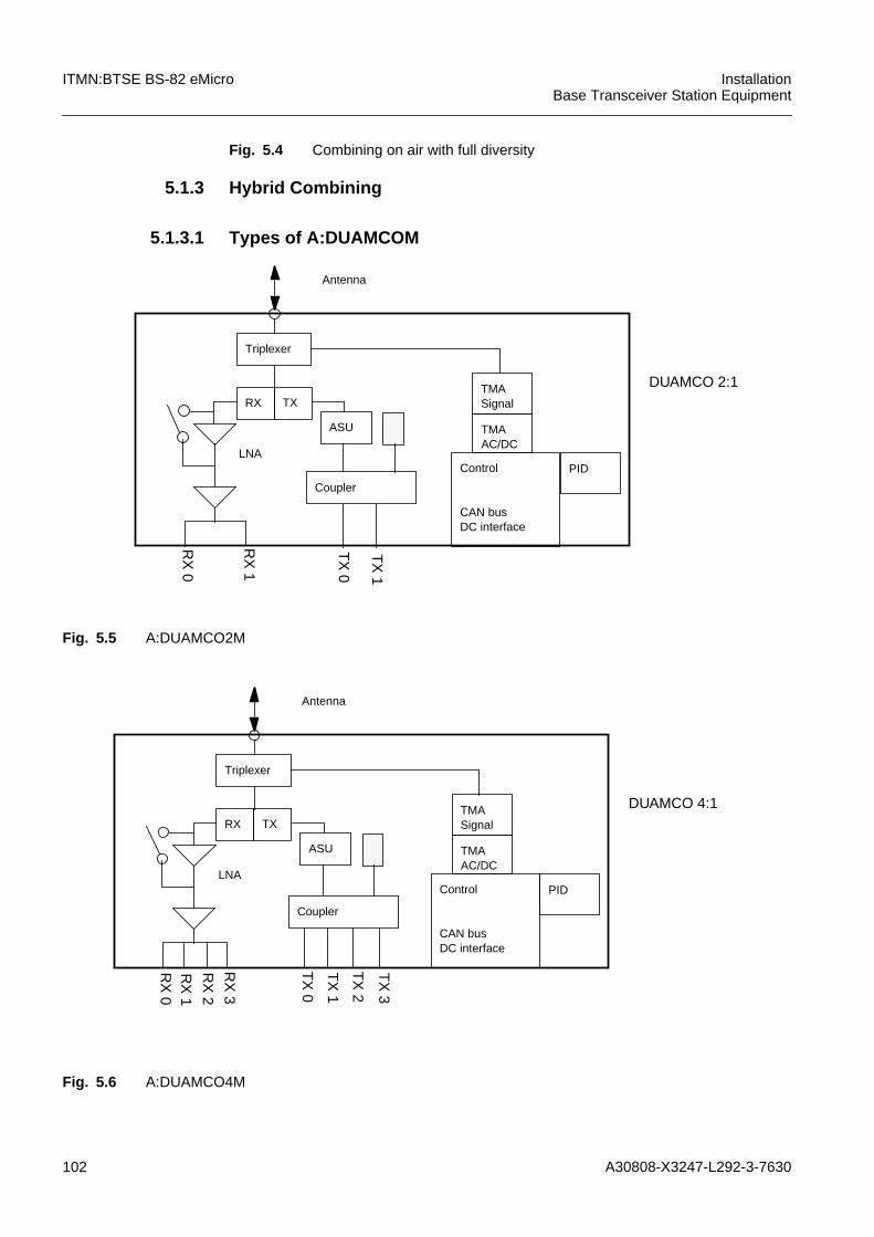
102 A30808-X3247-L292-3-7630
ITMN:BTSE BS-82 eMicro InstallationBase Transceiver Station Equipment
Fig. 5.4 Combining on air with full diversity
5.1.3 Hybrid Combining
5.1.3.1 Types of A:DUAMCOM
Fig. 5.5 A:DUAMCO2M
Fig. 5.6 A:DUAMCO4M
Triplexer
RX TX
Antenna
Control
CAN busDC interface
TMAAC/DC
TMASignal
PID
ASU
TX
1
TX
0
LNA
RX
1
RX
0
DUAMCO 2:1
Coupler
RX
0
RX
2
RX
1
RX
3
TX
0
TX
3
TX
2
TX
1
Triplexer
RX TX
Antenna
Control
CAN busDC interface
TMAAC/DC
TMASignal
PID
Coupler
ASU
LNA
DUAMCO 4:1
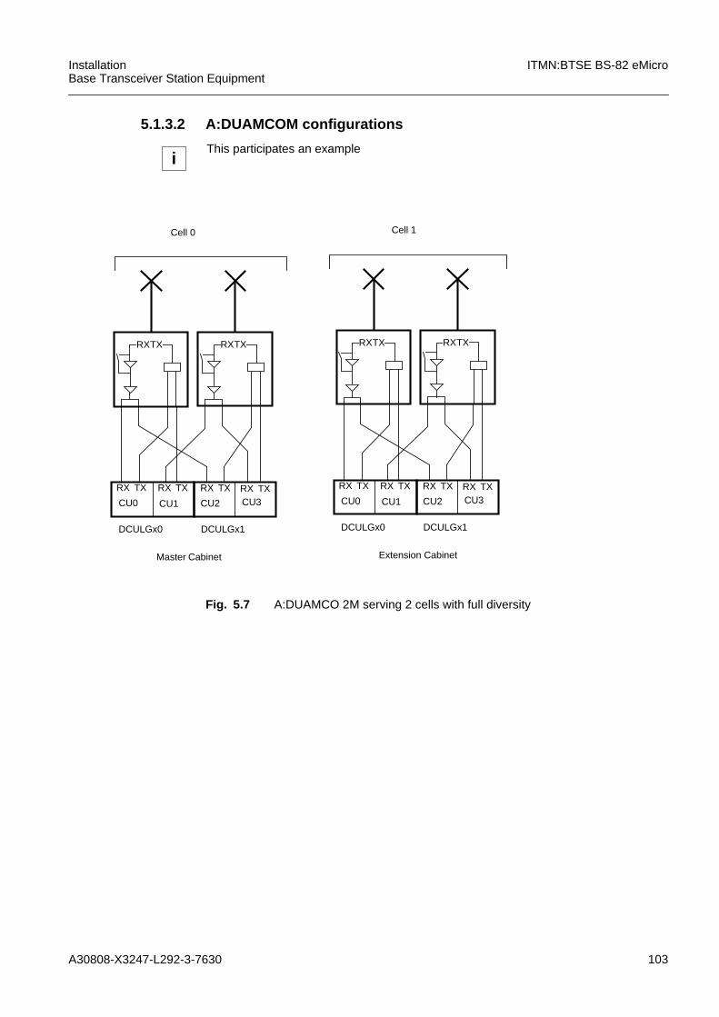
A30808-X3247-L292-3-7630 103
InstallationBase Transceiver Station Equipment
ITMN:BTSE BS-82 eMicro
5.1.3.2 A:DUAMCOM configurations
Fig. 5.7 A:DUAMCO 2M serving 2 cells with full diversity
iThis participates an example
DCULGx0 DCULGx1
RX TX
Cell 0
Master Cabinet
CU0 CU1 CU2 CU3
RXTX
RX TX RX TX RX TX
RXTX
DCULGx0 DCULGx1
RX TX
Extension Cabinet
Cell 1
CU0 CU1 CU2 CU3
RXTX
RX TX RX TX RX TX
RXTX
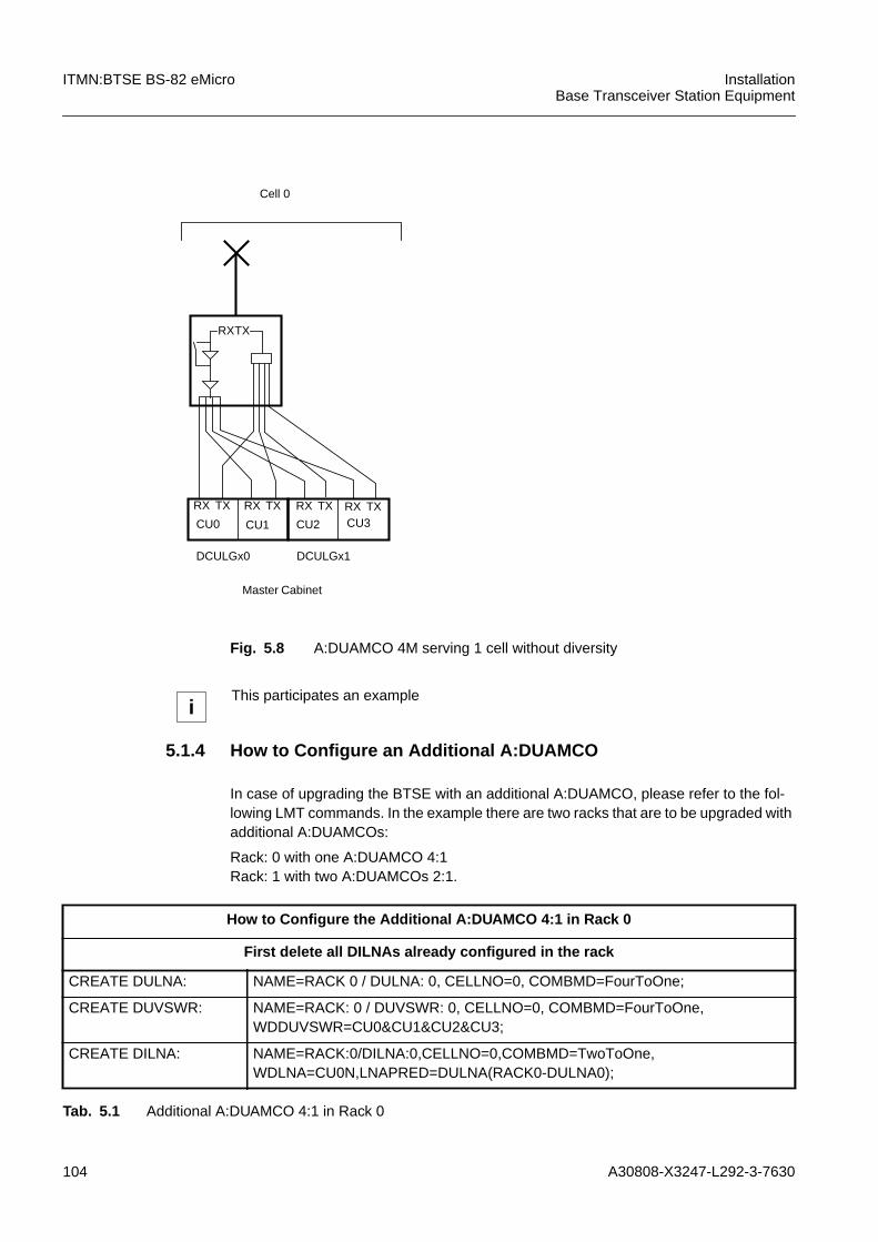
104 A30808-X3247-L292-3-7630
ITMN:BTSE BS-82 eMicro InstallationBase Transceiver Station Equipment
Fig. 5.8 A:DUAMCO 4M serving 1 cell without diversity
5.1.4 How to Configure an Additional A:DUAMCO
In case of upgrading the BTSE with an additional A:DUAMCO, please refer to the fol-lowing LMT commands. In the example there are two racks that are to be upgraded withadditional A:DUAMCOs:
Rack: 0 with one A:DUAMCO 4:1Rack: 1 with two A:DUAMCOs 2:1.
DCULGx0 DCULGx1
RX TX
Cell 0
Master Cabinet
CU0 CU1 CU2 CU3
RXTX
RX TX RX TX RX TX
iThis participates an example
How to Configure the Additional A:DUAMCO 4:1 in Rack 0
First delete all DILNAs already configured in the rack
CREATE DULNA: NAME=RACK 0 / DULNA: 0, CELLNO=0, COMBMD=FourToOne;
CREATE DUVSWR: NAME=RACK: 0 / DUVSWR: 0, CELLNO=0, COMBMD=FourToOne,WDDUVSWR=CU0&CU1&CU2&CU3;
CREATE DILNA: NAME=RACK:0/DILNA:0,CELLNO=0,COMBMD=TwoToOne,WDLNA=CU0N,LNAPRED=DULNA(RACK0-DULNA0);
Tab. 5.1 Additional A:DUAMCO 4:1 in Rack 0

A30808-X3247-L292-3-7630 105
InstallationBase Transceiver Station Equipment
ITMN:BTSE BS-82 eMicro
5.1.5 Change of Combiner Configuration
If the HW configuration of a BTSE is updated and some combiners configurations arechanged, the BTSE has to be configured in the following order:
1. Delete all existing combiners in the cell where a combiner is removed
2. Create all needed combiners with the new configuration. Otherwise it could be hap-pen that some TRXs of the cell remain disabled.
CREATE DILNA: NAME=RACK:0/DILNA:1,CELLNO=0,COMBMD=TwoToOne,WDLNA=CU1N,LNAPRED=DULNA(RACK0-DULNA0);
CREATE DILNA: NAME=RACK:0/DILNA:2,CELLNO=0,COMBMD=TwoToOne,WDLNA=CU2N,LNAPRED=DULNA(RACK0-DULNA0);
CREATE DILNA: NAME=RACK:0/DILNA:3,CELLNO=0,COMBMD=TwoToOne,WDLNA=CU3N,LNAPRED=DULNA(RACK0-DULNA0);
How to Configure the Additional A:DUAMCO 4:1 in Rack 0
First delete all DILNAs already configured in the rack
Tab. 5.1 Additional A:DUAMCO 4:1 in Rack 0
How to Configure the Additional Two A:DUAMCOs 2:1 in Rack 1
First delete all DILNAs already configured in the rack
CREATE DILNA: NAME=RACK:1/DILNA:0,CELLNO=0,COMBMD=TwoToOne,WDLNA=CU0N,LNAPRED=DULNA(RACK1-DULNA0);
CREATE DILNA: NAME=RACK:1/DILNA:1,CELLNO=0,COMBMD=TwoToOne,WDLNA=CU1N,LNAPRED=DULNA(RACK1-DULNA1);
CREATE DILNA: NAME=RACK:1/DILNA:2,CELLNO=0,COMBMD=TwoToOne,WDLNA=CU2N,LNAPRED=DULNA(RACK1-DULNA0);
CREATE DILNA: NAME=RACK:1/DILNA:3,CELLNO=0,COMBMD=TwoToOne,WDLNA=CU3N,LNAPRED=DULNA(RACK1-DULNA1);
CREATE DULNA: NAME=RACK:1/DULNA:0,CELLNO=0,COMBMD=TwoToOne;
CREATE DULNA: NAME=RACK:1/DULNA:1,CELLNO=0,COMBMD=TwoToOne;
CREATE DUVSWR: NAME=RACK:1/DUVSWR:0,CELLNO=0,COMBMD=TwoToOne,WDDUVSWR=CU0&CU1;
CREATE DUVSWR: NAME=RACK:1/DUVSWR:1,CELLNO=0,COMBMD=TwoToOne,WDDUVSWR=CU2&CU3;
Tab. 5.2 Additional A:DUAMCOs 2:1
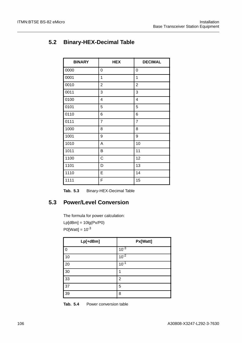
106 A30808-X3247-L292-3-7630
ITMN:BTSE BS-82 eMicro InstallationBase Transceiver Station Equipment
5.2 Binary-HEX-Decimal Table
5.3 Power/Level Conversion
The formula for power calculation:
Lp[dBm] = 10lg(Px/P0)
P0[Watt] = 10-3
BINARY HEX DECIMAL
0000 0 0
0001 1 1
0010 2 2
0011 3 3
0100 4 4
0101 5 5
0110 6 6
0111 7 7
1000 8 8
1001 9 9
1010 A 10
1011 B 11
1100 C 12
1101 D 13
1110 E 14
1111 F 15
Tab. 5.3 Binary-HEX-Decimal Table
Lp[+dBm] Px[Watt]
0 10-3
10 10-2
20 10-1
30 1
33 2
37 5
39 8
Tab. 5.4 Power conversion table
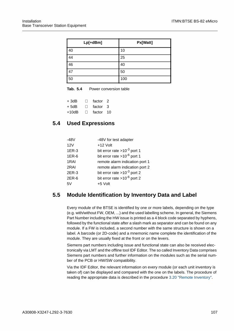
A30808-X3247-L292-3-7630 107
InstallationBase Transceiver Station Equipment
ITMN:BTSE BS-82 eMicro
5.4 Used Expressions
5.5 Module Identification by Inventory Data and Label
Every module of the BTSE is identified by one or more labels, depending on the type(e.g. with/without FW, OEM, ...) and the used labelling scheme. In general, the SiemensPart Number including the HW issue is printed as a 4 block code separated by hyphens,followed by the functional state after a slash mark as separator and can be found on anymodule. If a FW is included, a second number with the same structure is shown on alabel. A barcode (or 2D-code) and a mnemonic name complete the identification of themodule. They are usually fixed at the front or on the levers.
Siemens part numbers including issue and functional state can also be received elec-tronically via LMT and the offline tool IDF Editor. The so called Inventory Data comprisesSiemens part numbers and further information on the modules such as the serial num-ber of the PCB or HW/SW compatibility.
Via the IDF Editor, the relevant information on every module (or each unit inventory istaken of) can be displayed and compared with the one on the labels. The procedure ofreading the appropriate data is described in the procedure 3.20 "Remote Inventory".
40 10
44 25
46 40
47 50
50 100
Lp[+dBm] Px[Watt]
Tab. 5.4 Power conversion table
+ 3dB ≅ factor 2+ 5dB ≅ factor 3+10dB ≅ factor 10
-48V -48V for test adapter12V +12 Volt1ER-3 bit error rate >10-3 port 11ER-6 bit error rate >10-6 port 11RAI remote alarm indication port 12RAI remote alarm indication port 22ER-3 bit error rate >10-3 port 22ER-6 bit error rate >10-6 port 25V +5 Volt
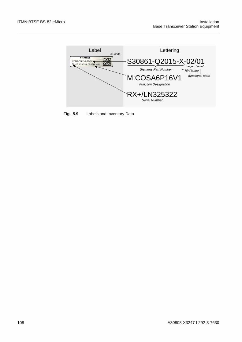
108 A30808-X3247-L292-3-7630
ITMN:BTSE BS-82 eMicro InstallationBase Transceiver Station Equipment
Fig. 5.9 Labels and Inventory Data
S30861-Q2015-X-02/01
M:COSA6P16V1+Siemens Part Number HW issue
functional state
Function Designation
Label Lettering2D-code
RX+/LN325322Serial Number

A30808-X3247-L292-3-7630 109
InstallationBase Transceiver Station Equipment
ITMN:BTSE BS-82 eMicro
6 AbbreviationsAC Alternating Current
ACPSC Alternating Current Power Supply and Con-trol
ANT Antenna Transmitter Output
AST Administrative State
ASU Antenna Supervision Unit
ATMN Acceptance Test Manual
BSC Base Station Controller
BSS Basestation Subsystem
BTS Base Transceiver Station
COBA Core Basis
DC Direct Current
DCPSC Direct Current Power Supply and Control
DCU Dual Carrier Unit
DILNA Diversity Low Noise Amplifier
DUAMCO Duplexer Amplifier Multicoupler
DULNA Duplexer Low Noise Amplifier
ESD Electrostatic Device
FFU For Future Use
FW Firmware
HMO Hardware related Managed Object
HMO Hardware Related Managed Objects
HW Hardware
IDT Inventory Data Table
IMN Installation Manual
INTENNA Internal Antenna
LED Light Emitting Diode
LMT Local Maintenance Terminal
LNA Low Noice Amplifier
LRU Least Replaceable Units
MMN Maintenance Manual
MO Managed Object
NE Network Element
NOB nob_RIUs only
nob_RIU not on-board Remote Inventory Data
ob_RIU on-board Remote Inventory Data
OEM Original Equipment Manufacturer
OVPT Overvoltage Protection and Tracer
PCB Printed Circuit Board
PID Product Identification Data
110 A30808-X3247-L292-3-7630
ITMN:BTSE BS-82 eMicro InstallationBase Transceiver Station Equipment
RFA Ready for Acceptance
RX Receiver
SWI Software Image
SWL Software Load
TAC Technical Assistance Center
TAD Test Adapter
TE Test Equipment
TMA Tower Mounted Amplifier
TNF Tunable Narrowband Filter
TRX Transceiver


