Embed Size (px)
DESCRIPTION
BS ISO 16232-4 2007
Citation preview

BRITISH STANDARD BS ISO 16232-4:2007
Road vehicles — Cleanliness of components of fluid circuits —Part 4: Method of extraction of contaminants by ultrasonic techniques
ICS 13.040.50; 43.180
�������������� ���������������������������������������������������
Lice
nsed
Cop
y: In
stitu
te O
f Tec
hnol
ogy
Tal
lagh
t, In
stitu
te o
f Tec
hnol
ogy,
Sun
Jul
15
09:3
2:44
GM
T+
00:0
0 20
07, U
ncon
trol
led
Cop
y, (
c) B
SI

BS ISO 16232-4:2007
This British Standard was published under the authority of the Standards Policy and Strategy Committee on 29 June 2007
© BSI 2007
ISBN 978 0 580 50925 4
National foreword
This British Standard was published by BSI. It is the UK implementation of ISO 16232-4:2007. The UK participation in its preparation was entrusted to Technical Committee MCE/22, Engines for road vehicles.A list of organizations represented on this committee can be obtained on request to its secretary.This publication does not purport to include all the necessary provisions of a contract. Users are responsible for its correct application.Compliance with a British Standard cannot confer immunity from legal obligations.
Amendments issued since publication
Amd. No. Date Comments
Lice
nsed
Cop
y: In
stitu
te O
f Tec
hnol
ogy
Tal
lagh
t, In
stitu
te o
f Tec
hnol
ogy,
Sun
Jul
15
09:3
2:44
GM
T+
00:0
0 20
07, U
ncon
trol
led
Cop
y, (
c) B
SI

Reference numberISO 16232-4:2007(E)
INTERNATIONAL STANDARD
ISO16232-4
First edition2007-06-01
Road vehicles — Cleanliness of components of fluid circuits — Part 4: Method of extraction of contaminants by ultrasonic techniques
Véhicules routiers — Propreté des composants des circuits de fluide —
Partie 4: Méthode d'extraction des contaminants par ultrasons
BS ISO 16232-4:2007
Lice
nsed
Cop
y: In
stitu
te O
f Tec
hnol
ogy
Tal
lagh
t, In
stitu
te o
f Tec
hnol
ogy,
Sun
Jul
15
09:3
2:44
GM
T+
00:0
0 20
07, U
ncon
trol
led
Cop
y, (
c) B
SI

ii
Lice
nsed
Cop
y: In
stitu
te O
f Tec
hnol
ogy
Tal
lagh
t, In
stitu
te o
f Tec
hnol
ogy,
Sun
Jul
15
09:3
2:44
GM
T+
00:0
0 20
07, U
ncon
trol
led
Cop
y, (
c) B
SI

iii
Contents Page
Foreword............................................................................................................................................................ iv Introduction ........................................................................................................................................................ v 1 Scope ..................................................................................................................................................... 1 2 Normative references ........................................................................................................................... 1 3 Terms and definitions........................................................................................................................... 2 4 Principle................................................................................................................................................. 2 5 Equipment ............................................................................................................................................. 2 5.1 General................................................................................................................................................... 2 5.2 Test liquid .............................................................................................................................................. 2 5.3 Test component container................................................................................................................... 2 5.4 Ultrasonic equipment ........................................................................................................................... 3 5.5 Pressure rinsing liquid dispenser....................................................................................................... 3 5.6 Vacuum suction system....................................................................................................................... 3 5.7 Collection equipment ........................................................................................................................... 3 5.8 Sampling containers............................................................................................................................. 3 5.9 Environmental conditions.................................................................................................................... 4 5.10 Health and safety .................................................................................................................................. 4 6 Procedure .............................................................................................................................................. 4 6.1 Handling and storage ........................................................................................................................... 4 6.2 Extraction procedure set-up and validation ...................................................................................... 4 6.3 Blank test............................................................................................................................................... 7 6.4 Component routine test ....................................................................................................................... 9 7 Analysis of the extraction liquid ......................................................................................................... 9 8 Presentation of results ....................................................................................................................... 10 Annex A (informative) Set up using ultrasonic techniques ......................................................................... 11 Annex B (informative) Synopsis of extraction procedure set up and validation....................................... 13 Annex C (informative) Example of data sheet for the extraction procedure by ultrasonic
techniques ........................................................................................................................................... 14 Annex D (informative) Synopsis of the routine test procedure................................................................... 17 Bibliography ..................................................................................................................................................... 18
BS ISO 16232-4:2007
Lice
nsed
Cop
y: In
stitu
te O
f Tec
hnol
ogy
Tal
lagh
t, In
stitu
te o
f Tec
hnol
ogy,
Sun
Jul
15
09:3
2:44
GM
T+
00:0
0 20
07, U
ncon
trol
led
Cop
y, (
c) B
SI

iv
Foreword
ISO (the International Organization for Standardization) is a worldwide federation of national standards bodies (ISO member bodies). The work of preparing International Standards is normally carried out through ISO technical committees. Each member body interested in a subject for which a technical committee has been established has the right to be represented on that committee. International organizations, governmental and non-governmental, in liaison with ISO, also take part in the work. ISO collaborates closely with the International Electrotechnical Commission (IEC) on all matters of electrotechnical standardization.
International Standards are drafted in accordance with the rules given in the ISO/IEC Directives, Part 2.
The main task of technical committees is to prepare International Standards. Draft International Standards adopted by the technical committees are circulated to the member bodies for voting. Publication as an International Standard requires approval by at least 75 % of the member bodies casting a vote.
Attention is drawn to the possibility that some of the elements of this document may be the subject of patent rights. ISO shall not be held responsible for identifying any or all such patent rights.
ISO 16232-4 was prepared by Technical Committee ISO/TC 22, Road vehicles, Subcommittee SC 5, Engine test.
ISO 16232 consists of the following parts, under the general title Road vehicles — Cleanliness of components of fluid circuits:
⎯ Part 1: Vocabulary
⎯ Part 2: Method of extraction of contaminants by agitation
⎯ Part 3: Method of extraction of contaminants by pressure rinsing
⎯ Part 4: Method of extraction of contaminants by ultrasonic techniques
⎯ Part 5: Method of extraction of contaminants on functional test bench
⎯ Part 6: Particle mass determination by gravimetric analysis
⎯ Part 7: Particle sizing and counting by microscopic analysis
⎯ Part 8: Particle nature determination by microscopic analysis
⎯ Part 9: Particle sizing and counting by automatic light extinction particle counter
⎯ Part 10: Expression of results
BS ISO 16232-4:2007
Lice
nsed
Cop
y: In
stitu
te O
f Tec
hnol
ogy
Tal
lagh
t, In
stitu
te o
f Tec
hnol
ogy,
Sun
Jul
15
09:3
2:44
GM
T+
00:0
0 20
07, U
ncon
trol
led
Cop
y, (
c) B
SI
v
Introduction
The presence of particulate contamination in a fluid system is acknowledged to be a major factor governing the life and reliability of that system. The presence of particles residual from the manufacturing and assembly processes will cause a substantial increase in the wear rates of the system during the initial run-up and early life, and may even cause catastrophic failures.
In order to achieve reliable performance of components and systems, control over the amount of particles introduced during the build phase is necessary, and measurement of particulate contaminants is the basis of control.
The ISO 16232 series has been drafted to fulfil the requirements of the automotive industry, since the function and performance of modern automotive fluid components and systems are sensitive to the presence of a single or a few critically sized particles. Consequently, ISO 16232 requires the analysis of the total volume of extraction liquid and of all contaminants collected using an approved extraction method.
The ISO 16232 series has been based on existing ISO International Standards such as those developed by ISO/TC 131/SC6. These International Standards have been extended, modified and new ones have been developed to produce a comprehensive suite of International Standards to measure and report the cleanliness levels of parts and components fitted to automotive fluid circuits.
This part of ISO 16232 defines procedures for the removal and collection of contaminants from components using ultrasonic bath or an ultrasonic probe so that their cleanliness can be evaluated.
The cleanliness level of a component, as determined according to this method, depends to a large extent on the test parameters (e.g. the frequency, the power and duration of the ultrasound and the type of application, bath or sonotrode). It is advisable that all parameters be included in the inspection document and rigorously followed by the test staff.
BS ISO 16232-4:2007
Lice
nsed
Cop
y: In
stitu
te O
f Tec
hnol
ogy
Tal
lagh
t, In
stitu
te o
f Tec
hnol
ogy,
Sun
Jul
15
09:3
2:44
GM
T+
00:0
0 20
07, U
ncon
trol
led
Cop
y, (
c) B
SI
blank
Lice
nsed
Cop
y: In
stitu
te O
f Tec
hnol
ogy
Tal
lagh
t, In
stitu
te o
f Tec
hnol
ogy,
Sun
Jul
15
09:3
2:44
GM
T+
00:0
0 20
07, U
ncon
trol
led
Cop
y, (
c) B
SI

1
Road vehicles — Cleanliness of components of fluid circuits —
Part 4: Method of extraction of contaminants by ultrasonic techniques
1 Scope
This part of ISO 16232 describes the principles of extraction of contaminants from a component either by immersion in an ultrasonic bath or by applying ultrasonic vibrations directly via sonotrodes. It is preferably applied to small and medium sized components of various geometry of which both internal and/or external surfaces have to be examined (e.g. joint seals, gears, etc). It is also applicable to small parts to be analysed in batches.
This method can be used on its own or in association with other methods of extraction described in the ISO 16232 series.
NOTE 1 The suitability of this method for complex geometries – e.g. tiny bores or large cavities with small openings – is decided on a case by case basis.
NOTE 2 Depending on the shape of the components, this method can be used also for batches containing multiple layers of components provided that there is no obstruction to the extraction of contaminants from the surface and their subsequent transfer into the test liquid. Small compact parts of large number are cleaned in a single layer.
Unless otherwise specified, this part of ISO 16232 deals with particulate contamination only. It does not, therefore, cover appearance defects or contamination by liquid or gaseous materials. It covers the amount and the nature of residual particles resulting from manufacturing processes and from the environment.
2 Normative references
The following referenced documents are indispensable for the application of this document. For dated references, only the edition cited applies. For undated references, the latest edition of the referenced document (including any amendments) applies.
ISO 16232-1, Road vehicles — Cleanliness of components of fluid circuits — Part 1: Vocabulary
ISO 16232-2, Road vehicles — Cleanliness of components of fluid circuits — Part 2: Method of extraction of contaminants by agitation
ISO 16232-3, Road vehicles — Cleanliness of components of fluid circuits — Part 3: Method of extraction of contaminants by pressure rinsing
ISO 16232-5, Road vehicles — Cleanliness of components of fluid circuits — Part 5: Method of extraction of contaminants on functional test bench
ISO 16232-6, Road vehicles — Cleanliness of components of fluid circuits — Part 6: Particle mass determination by gravimetric analysis
ISO 16232-7, Road vehicles — Cleanliness of components of fluid circuits — Part 7: Particle sizing and counting by microscopic analysis
BS ISO 16232-4:2007
Lice
nsed
Cop
y: In
stitu
te O
f Tec
hnol
ogy
Tal
lagh
t, In
stitu
te o
f Tec
hnol
ogy,
Sun
Jul
15
09:3
2:44
GM
T+
00:0
0 20
07, U
ncon
trol
led
Cop
y, (
c) B
SI

2
ISO 16232-8, Road vehicles — Cleanliness of components of fluid circuits — Part 8: Particle nature determination by microscopic analysis
ISO 16232-9, Road vehicles — Cleanliness of components of fluid circuits — Part 9: Particle sizing and counting by automatic light extinction particle counter
ISO 16232-10:2007, Road vehicles — Cleanliness of components of fluid circuits — Part 10: Expression of results
3 Terms and definitions
For the purposes of this document, the terms and definitions given in ISO 16232-1 apply.
4 Principle
The contaminants are extracted from the surface of the component by ultrasound. The cleaning effect is due to the cavitation, which creates micro-bubbles that implode close to the particles which are then expelled from and transferred to the extraction liquid for subsequent analysis.
NOTE 1 In case of an active component, the particles are extracted from the entire controlled surface of the component by traversing liquid.
NOTE 2 Several operating parameters influence the extraction efficiency, e.g. power density, operating time and medium, the placement and orientation of the component in relation to the ultrasonic source and the material the component is made of.
5 Equipment
5.1 General
The equipment used shall neither alter nor modify the size distribution of the extracted particles.
5.2 Test liquid
The test liquid shall be compatible with all the materials in the component, with the liquid used in the final system and with the test equipment, including seals, membrane filters and clean-up filters. A test liquid of low viscosity (u 5 mm2/s) and having the capability of removing (or dissolving) oil and grease is recommended. It should be filtered to attain the requirements of 6.3.3.
SAFETY PRECAUTIONS — In case a tested component will be reclaimed for final use, application of incompatible test liquid may cause hazardous damage.
5.3 Test component container
A closed container should be used for the transfer of the component from the place of sampling to the place of particle extraction. This container shall be appropriate to the shape of the component and made of material compatible with the test liquid. Its degree of cleanliness shall comply with the blank requirements specified in 6.3.3.
BS ISO 16232-4:2007
Lice
nsed
Cop
y: In
stitu
te O
f Tec
hnol
ogy
Tal
lagh
t, In
stitu
te o
f Tec
hnol
ogy,
Sun
Jul
15
09:3
2:44
GM
T+
00:0
0 20
07, U
ncon
trol
led
Cop
y, (
c) B
SI

3
5.4 Ultrasonic equipment
5.4.1 Ultrasonic bath
The ultrasonic bath should be made of stainless steel. The principal characteristics of the ultrasonic equipment (notably power, frequency, and dimensions of the bath) shall be specified in the test report and the inspection document. In general, by applying transducers to the floor or to the wall surfaces of the bath, it is possible to achieve a high degree of homogeneous sonic distribution and therefore a homogeneous cleaning effect.
If the extraction liquid is in direct contact with the ultrasonic bath, the latter shall be processed like a collection container.
5.4.2 Sonotrodes
Another possibility for transferring ultrasonic energy to the test liquid is by using sonotrodes. These are mechanical elements that transmit ultrasound and transfer it to the test liquid to be sonically treated. The mass and geometry of these elements are aligned with the frequency of the ultrasound. For this application they are usually rod-shaped and made of titanium and most of the ultrasonic energy is radiated via the tip.
Sonotrodes are used in the extraction procedures for such internal geometries as through-boring, blind holes and channels which are less suitable for cleaning in an immersion ultrasonic bath.
NOTE Due to the high power densities that can be attained using sonotrodes, great care has to be taken to avoid cavitation damage to component(s) under test.
5.5 Pressure rinsing liquid dispenser
The pressure liquid dispenser is a device that provides clean test liquid specified in 5.2 at a pressure and flow rate capable of extracting the contaminants in an effective manner. The dispenser can also be used to rinse the test equipment and all other items.
NOTE This device can be the same as the one used for providing the test liquid.
5.6 Vacuum suction system
If necessary, use an assembly consisting of a source of vacuum, a vacuum flask previously cleaned and a flexible tube of suitable dimensions and shape for recovery of the extraction liquid and any particles that have accumulated in the component under examination.
5.7 Collection equipment
The collection equipment shall allow effective draining of contaminants. A conical base is preferred.
It shall be cleaned to achieve the requirements of 6.3.3.
It is possible for contaminants remaining on the equipment to be transferred to the sample and thus be erroneously included as part of the particles removed from the component. All collection equipment shall be cleaned and covered before use in order to limit contamination from the environment.
5.8 Sampling containers
The sampling containers (glassware, etc.) required for transferring the extraction liquid from the collection equipment to the analysis equipment shall be cleaned to achieve the requirements of 6.3.3.
BS ISO 16232-4:2007
Lice
nsed
Cop
y: In
stitu
te O
f Tec
hnol
ogy
Tal
lagh
t, In
stitu
te o
f Tec
hnol
ogy,
Sun
Jul
15
09:3
2:44
GM
T+
00:0
0 20
07, U
ncon
trol
led
Cop
y, (
c) B
SI

4
5.9 Environmental conditions
The cleanliness of the environment where the extraction is performed shall be consistent with the presumed cleanliness of the component to test. This requirement may result in the test being carried out in a laboratory or controlled workplace. The suitability of the environment is validated when performing the blank test.
5.10 Health and safety
5.10.1 Local Health and Safety procedures shall be followed at all times, any equipment shall be operated in accordance with the manufacturer's instruction and personal protection equipment used where appropriate.
5.10.2 Chemicals used in the procedures can be harmful, toxic or flammable. Good laboratory practices shall be observed in the preparation and use of these chemicals. Care shall be taken to ensure compatibility of the chemicals with the materials used (refer to each Material Safety Data Sheet [MSDS]). Follow the precautions for safe handling and usage as described in the MSDS available from the supplier.
5.10.3 Volatile liquids; care shall be taken with flammable liquids to ensure that they are used in accordance with the MSDS, at temperatures below the stated flash point and away from potential sources of ignition. Appropriate precautions should be taken to avoid inhalation of fumes from these solvents. Always use suitable protective equipment.
5.10.4 Electrical; appropriate care should be applied in the use of electrical power.
5.10.5 Disposal; all liquids and substances shall be disposed of in accordance with local environmental procedures. In the event of spillage it shall be cleaned-up in the manner detailed in the MSDS.
6 Procedure
6.1 Handling and storage
During handling and storage of test components, it shall be ensured that no contaminants are deposited on or removed from controlled surfaces.
To prevent loss of particles during transport it may be necessary to seal openings of the test components, e.g. with suitable plugs.
6.2 Extraction procedure set-up and validation
6.2.1 The number of components to be analysed shall be chosen so as to measure a significant amount of contaminants that complies with the requirements for a blank (see 6.2.15 NOTE 3).
6.2.2 If the break-in of the component is part of its manufacturing process, the extraction procedure should be agreed between parties and included in the inspection document because break-in may alter its initial cleanliness level.
6.2.3 If the particles that are detached during transportation of the test component and/or particles from the packaging are to be included in the cleanliness inspection, as agreed upon between parties, they shall be collected using the appropriate extraction method (e.g. low pressure rinsing). This agreement shall be included in the inspection document.
6.2.4 The effectiveness of the ultrasonic method depends on the following, non-exhaustive list of parameters: the frequency, the power and duration of the ultrasonic vibrations and the type of application – bath or sonotrode (see Annex A for practical information). A synopsis of the operations to perform is given in Annex B. The detailed description of operating conditions and equipment used in application of this standard to extract the contaminants from the component by ultrasonic techniques constitutes the extraction procedure. This procedure shall be established for each component and shall be both agreed between parties and
BS ISO 16232-4:2007
Lice
nsed
Cop
y: In
stitu
te O
f Tec
hnol
ogy
Tal
lagh
t, In
stitu
te o
f Tec
hnol
ogy,
Sun
Jul
15
09:3
2:44
GM
T+
00:0
0 20
07, U
ncon
trol
led
Cop
y, (
c) B
SI
5
included in the inspection document. Details of the procedure shall be reported on a suitable data sheet (for an example of extraction procedure data sheet see Annex C).
6.2.5 If needed for reporting results and if not specified, determine the controlled and/or controlled surface area of the component volume under examination (see Annex B of ISO 16232-10:2007). Report and/or specify their values in the inspection document.
6.2.6 Before starting to set up or validate any extraction protocol/equipment, it is necessary to perform an initial blank test to know the cleanliness of the equipment. This is performed after cleaning the equipment and the initial blank shall exhibit values stated in 6.3.3.
NOTE Conditioning and cleaning serves the purpose of obtaining a suitable cleanliness level of the inspection set-up. It is recommended that a basic procedure for conditioning the inspection set-up be defined. For example, by performing a cleanliness analysis of a defined volume of liquid after the cleaning procedure of the set-up, it can be determined whether the inspection environment is suitable for carrying out a validation procedure.
6.2.7 If necessary, demagnetise the component and/or clean those external surfaces which are not involved in the cleanliness test.
6.2.8 The external surface should be cleaned in a physically different place from where extraction is to be carried out. Ensure that no contaminants are deposited on or removed from controlled surfaces. For example, if the component is of large size, a tank for example, clean only those external surfaces which might contribute to contamination during the extraction process.
6.2.9 If necessary, remove all covers and other plugs fitted for transport of the component. If the component contains a shipment liquid, empty it out, measure its volume and analyse its contaminants according to Clause 7.
NOTE Removal of plugs might generate contaminants to unavoidably contribute to the original contamination.
6.2.10 If dismantling is necessary to obtain access to all the surfaces to be inspected, do so with care.
NOTE Any operation of dismantling might generate particles which could be added to or lost from the original amount of particles.
6.2.11 Extraction procedure using an ultrasonic bath.
6.2.11.1 If it is only the external surface of the component that is subject to the inspection process and if the component has no hollow parts opening to the exterior, proceed as indicated in 6.2.11.4. If it does have such hollow parts, carefully close their openings and proceed to 6.2.11.4.
6.2.11.2 If the internal and external surfaces of the component are the parts subject to the inspection process, proceed as described in 6.2.11.4.
6.2.11.3 If it is only the internal surface of the component that is subject to the inspection process, carefully rinse its external surface without rinsing particles into the controlled surface, fill it completely with test liquid, close it hermetically and then proceed as indicated in 6.2.11.4.
NOTE The process of closing or sealing the component may generate or introduce particles.
6.2.11.4 Completely immerse the component in a suitable container e.g. a glass beaker containing clean test liquid, or hang the component directly in the ultrasonic bath containing a suitable volume of clean test liquid.
If several surfaces of the component are to be tested, repeat ultrasonic treatment for each individual controlled surface. It may be necessary to turn the component with the surface under test facing toward the ultrasonic transducers.
6.2.11.5 Subject the component or its container to ultrasonic treatment at the power and frequency and for the duration specified in the inspection document.
BS ISO 16232-4:2007
Lice
nsed
Cop
y: In
stitu
te O
f Tec
hnol
ogy
Tal
lagh
t, In
stitu
te o
f Tec
hnol
ogy,
Sun
Jul
15
09:3
2:44
GM
T+
00:0
0 20
07, U
ncon
trol
led
Cop
y, (
c) B
SI

6
NOTE If ultrasound parameters are incorrectly selected, components may be damaged or materials may leach out from the component surface and the container (if used).
6.2.11.6 If 6.2.11.1 and/or 6.2.11.2 apply, remove the component from the extraction liquid, rinse the component over the collection equipment or ultrasonic bath by spraying with test liquid under pressure (see 5.6) and transfer the extraction liquid into a clean sampling container. For small components, rinsing can be performed directly into the funnel of the vacuum apparatus.
6.2.11.7 If 6.2.11.3 applies, remove the component from the ultrasonic bath and clean off any external contamination. Carefully remove the closures from the component and pour its contents into a clean sample container. Rinse the internal surface of the component with a suitable jet of filtered test liquid.
6.2.12 Extraction procedure using an ultrasonic sonotrode for hollow components.
6.2.12.1 Place the component in a beaker or other suitable container such that the opening of the component faces upwards and can be accessed by the sonotrode. Fill the beaker with a known quantity of test liquid. Take care to ensure that the internal geometry of the component to be tested is completely filled with test liquid.
6.2.12.2 Clean the outside of the sonotrode over its complete length with a jet of clean test liquid before introducing the sonotrode into the cavity of the component. If necessary, fix the sonotrode using a stand. The sonotrode should not touch any surface. Perform the ultrasonic treatment with the power and frequency and for the duration specified in the inspection document.
If several borings or cavities of the component are to be tested, repeat ultrasonic treatment for each individual controlled surface. It may be necessary to move or relocate the component to gain access by the sonotrode. This should be done carefully so as not to result in the loss of particles.
6.2.12.3 Remove the component, empty the extraction liquid into a suitable collection container and rinse it carefully with clean test liquid. After rinsing, ensure that the component has been completely emptied.
6.2.12.4 All equipment that has come into contact with the extraction liquid or the component, e.g. tip of the sonotrode, operator’s gloves, tweezers, etc. shall be thoroughly rinsed with clean test liquid collected in a suitable container and subsequently analysed. For convenience, this extraction liquid can be added to the main sample collected.
6.2.13 Analyse the extraction liquid as specified in Clause 7 and label the result obtained as S1.
6.2.14 Repeat 6.2.11 and/or 6.2.12 twice more on the same component, using, when necessary, a different container for each extraction and label the results obtained as S2 and S3 as appropriate.
NOTE The extractions should be made directly one after the other.
6.2.15 Validate the contaminant extraction procedure to ensure its efficacy as follows:
a) for each of the three samples analysed in 6.2.13, establish the total mass of contaminants and/or the total number of particles. For the particle count, this is applicable to the total number of particles larger than the smallest particle size specified in the inspection document. This particle size shall be chosen to enable counting of significant numbers of particles;
b) divide the result of the last sample by the sum of all the values obtained in 6.2.15 a);
c) if the value obtained is less than or equal to 10 %, the end-point is reached, and the extraction is completed.
NOTE 1 This procedure enables the extraction curve to be drawn and the end-point (w 0,10) to be demonstrated (see Figure 1).
NOTE 2 The cleanliness level of the component is the sum of the extractions.
BS ISO 16232-4:2007
Lice
nsed
Cop
y: In
stitu
te O
f Tec
hnol
ogy
Tal
lagh
t, In
stitu
te o
f Tec
hnol
ogy,
Sun
Jul
15
09:3
2:44
GM
T+
00:0
0 20
07, U
ncon
trol
led
Cop
y, (
c) B
SI

7
NOTE 3 In some cases (very low contamination level, difficulties in extracting particles, inappropriate blank level, etc.) the extraction curve may not be of the form seen in Figure 1. If this is the case, it is ensured that all extraction parameters have been properly investigated.
d) If the value obtained is > 0,10, a further extraction is necessary. Repeat stages 6.2.11 or 6.2.12 to 6.2.14 until the last sample produces a result u 0,10 of the total of the whole samples
6.2.16 If six extractions have been performed without reaching a value u 0,10, then the extraction parameters are not suitable and shall be modified. Repeat operations 6.2.4 to 6.2.14 with new parameters on a new component.
6.2.17 If this criterion is not fulfilled, set up a new extraction protocol and validate it according to 6.1 or apply another extraction method as defined in ISO 16232-2, ISO 16232-3 or ISO 16232-5.
Key
1 cleanliness level of Si 2 extraction sample i 3 blank Value
Figure 1 — Example of extraction curve
6.3 Blank test
6.3.1 Sources of blank contamination
6.3.1.1 The blank value accounts for contamination resulting from handling and testing the component, beginning when it is unpacked and ending after analysis procedure. Main sources of blank contamination are:
⎯ ambient air environment (air, operator, working area, etc.);
⎯ test liquid;
⎯ all non-component surfaces that come into contact with the extraction liquid such as containers and equipment for collecting and sampling the extraction liquid;
1 2 3 4 5 6 2
1
3
BS ISO 16232-4:2007
Lice
nsed
Cop
y: In
stitu
te O
f Tec
hnol
ogy
Tal
lagh
t, In
stitu
te o
f Tec
hnol
ogy,
Sun
Jul
15
09:3
2:44
GM
T+
00:0
0 20
07, U
ncon
trol
led
Cop
y, (
c) B
SI

8
⎯ analysis of the extraction liquid;
⎯ membrane filter or optical particle counter and associated equipment;
⎯ handling during preparation and analysis of extraction liquid samples.
The blank value results from the combination and interaction of the above factors being applied for a specific test task.
6.3.1.2 The cleanliness of the environment where the cleanliness inspection is performed should be known and be consistent with the presumed cleanliness of the component to be tested. This is validated when performing the blank test.
6.3.1.3 If the blank value level shifts towards higher values, the sources of blank contamination shall be investigated in order to avoid the specified blank level being exceeded in the future.
6.3.2 System blank test
6.3.2.1 A blank test is performed to verify that the operating conditions, equipment and products used in the extraction procedure do not contribute a significant amount of contamination to the component analysed. To ensure process consistency, a blank test should be performed at regular intervals using identical test parameters.
6.3.2.2 For the determination of system blank values, identical conditions as the one applied during testing of the component shall be applied but with the component omitted.
The blank value shall be determined and comply with the requirements for each analysis method specified in the inspection document.
6.3.2.3 Proceed as specified in 6.2.11 or 6.2.12 with the same equipment and volume of test liquid as required for analysis of the component, but without the component.
6.3.2.4 Analyse the extraction liquid as specified in Clause 7.
6.3.3 Blank value
6.3.3.1 General
The acceptable blank value depends on the component's presumed or specified cleanliness level and, depending on the analysis method, is as follows:
6.3.3.2 Gravimetric analysis
Less than 10 % of the presumed gravimetric cleanliness level.
NOTE Using a 4-digit balance under uncontrolled environmental conditions (uncontrolled humidity and temperature) the minimum measurable blank value is 0,3 mg. Thus at least 3 mg should be collected during the component test in order to meet the 10 % criterion.
6.3.3.3 Particle counting and sizing:
a) particle counts: less than or 10 % of the presumed or specified numbers at the relevant sizes, each calculated number being rounded down;
EXAMPLE:
For one particle size, the specified number is 16,
16 × 10 % = 1,6
BS ISO 16232-4:2007
Lice
nsed
Cop
y: In
stitu
te O
f Tec
hnol
ogy
Tal
lagh
t, In
stitu
te o
f Tec
hnol
ogy,
Sun
Jul
15
09:3
2:44
GM
T+
00:0
0 20
07, U
ncon
trol
led
Cop
y, (
c) B
SI
9
rounded value = 1
Conclusion: 1 particle is accepted in the blank.
NOTE The sizes specified in the inspection document for the blank should be as close as possible to the maximum particle size acceptable for the component and chosen to allow counting significant numbers of particles.
b) maximum particle size: no particle at the ISO 16232-10 size range next lower to the half of the presumed or specified maximum particle size;
EXAMPLE:
Maximum acceptable particle X = 350 µm 350 µm/2 = 175 µm.
This is size class G according to ISO 16232-10.
Next lower size class is F. That means no particles larger than 100 µm for the blank.
c) if the component cleanliness level is neither presumed nor specified, the blank shall exhibit:
⎯ less than 4 000 particles greater than 5 µm and less than 500 particles greater than 15 µm per 100 mL of extraction liquid.
⎯ no particle greater than 50 µm.
6.3.3.4 Blank level exceeding 10 %
If the blank level exceeds 10 %, it is possible to increase the number of test components analyzed in order to collect more particles and thus fulfil the 10 % limit.
6.4 Component routine test
A synopsis of the procedure is given in Annex D.
6.4.1 Apply the extraction described in 6.2.11 or 6.2.12 to the test component. It may be possible to use a combined extraction method by using the same overall test time used to validate the extraction procedure. In this case, the resulting cleanliness level may differ. This simplified method shall be validated and shall be agreed between parties and included in the inspection document.
If the particles detached during transportation of the test component and particles from the packaging are required to be included in the cleanliness test, they shall be collected using the appropriate extraction method (e.g. low pressure rinsing) as agreed upon between parties and included in the inspection document.
6.4.2 When several identical components are measured by a validated method, the cleanliness level of each extraction liquid sample is not required to be measured. All the samples collected in 6.2.11 or 6.2.12 can then be mixed and analyzed as specified in Clause 7.
NOTE When the extraction method is applied to several components due to their high level of cleanliness (in relation to the value of the blank level, etc.) it is not necessary to measure the contamination level of each extraction liquid sample. All the fluids collected in 6.2.11 or 6.2.12 are then mixed and analyzed as specified in Clause 7.
7 Analysis of the extraction liquid
7.1 All of the extraction liquid shall be analysed by the method appropriate to the expression of the result of the cleanliness inspection as specified in the inspection document:
⎯ gravimetric analysis in accordance with ISO 16232-6;
⎯ particle sizing and counting by microscopic analysis in accordance with ISO 16232-7;
BS ISO 16232-4:2007
Lice
nsed
Cop
y: In
stitu
te O
f Tec
hnol
ogy
Tal
lagh
t, In
stitu
te o
f Tec
hnol
ogy,
Sun
Jul
15
09:3
2:44
GM
T+
00:0
0 20
07, U
ncon
trol
led
Cop
y, (
c) B
SI

10
⎯ particle nature analysis by scanning electron microscopy and EDX in accordance with ISO 16232-8;
⎯ particle sizing and counting by light extinction automatic particle counter in accordance with ISO 16232-9.
7.2 The analysis shall be on the total volume of liquid used. As specified in the inspection document, all or some of the following liquid samples shall be analysed together provided that the liquids are completely miscible:
⎯ those containing the extracted particles;
⎯ those containing the particles from rinsing the collection equipment;
⎯ those containing the particles from rinsing any packaging;
⎯ those containing all liquid drained from the test item prior to the extraction process;
If the samples contain immiscible liquids then they shall be analysed separately, unless it can be verified that these liquids will not interfere with the analysis method chosen.
8 Presentation of results
An example of ultrasonic extraction data sheet is given in Annex C.
Express the results of the cleanliness measurement according to ISO 16232-10.
BS ISO 16232-4:2007
Lice
nsed
Cop
y: In
stitu
te O
f Tec
hnol
ogy
Tal
lagh
t, In
stitu
te o
f Tec
hnol
ogy,
Sun
Jul
15
09:3
2:44
GM
T+
00:0
0 20
07, U
ncon
trol
led
Cop
y, (
c) B
SI

11
Annex A (informative)
Set-up using ultrasonic techniques
A.1 Component directly immersed in the ultrasonic bath
Figure A.1 — Ultrasonic bath direct immersion
NOTE For cleaning the complete surface of the component rotation is required.
A.2 Components immersed in a beaker for extraction of particles in an ultrasonic bath
Figure A.2 — Ultrasonic bath indirect immersion
NOTE Small compact parts in large number are tested in single layer.
Transducer
Test item
Ultrasonic bath
Container
Test item
Transducer
BS ISO 16232-4:2007
Lice
nsed
Cop
y: In
stitu
te O
f Tec
hnol
ogy
Tal
lagh
t, In
stitu
te o
f Tec
hnol
ogy,
Sun
Jul
15
09:3
2:44
GM
T+
00:0
0 20
07, U
ncon
trol
led
Cop
y, (
c) B
SI
12
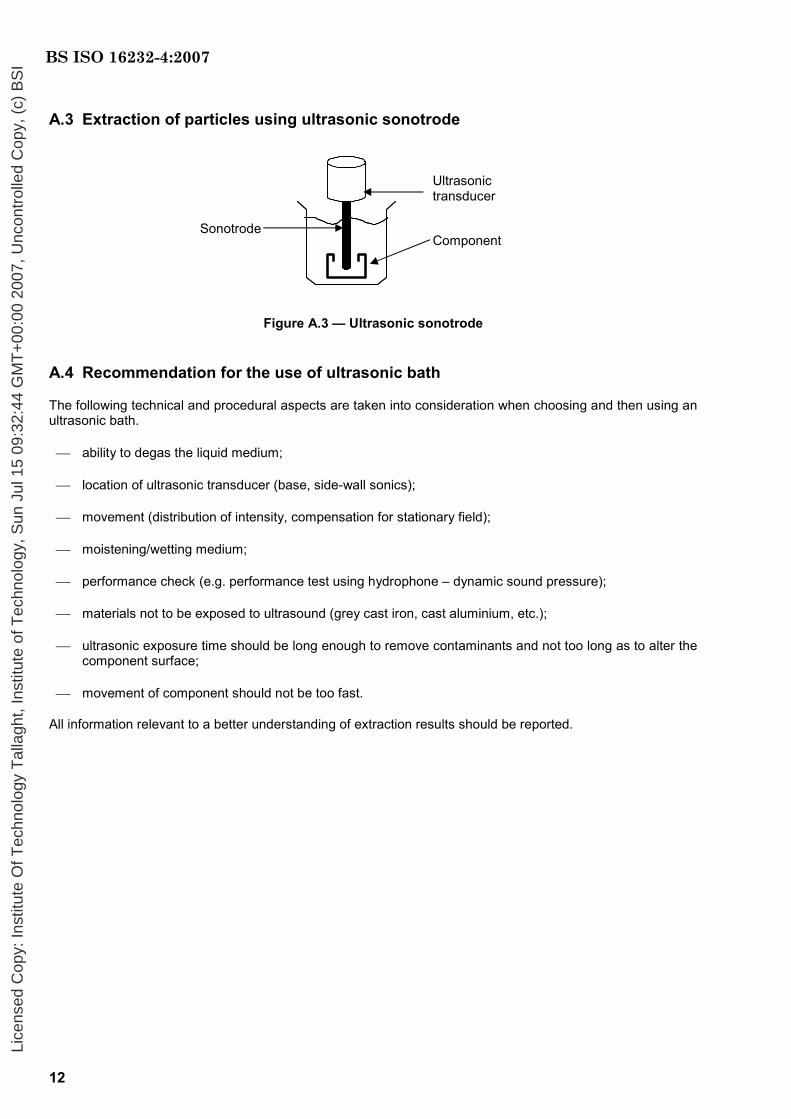
A.3 Extraction of particles using ultrasonic sonotrode
Figure A.3 — Ultrasonic sonotrode
A.4 Recommendation for the use of ultrasonic bath
The following technical and procedural aspects are taken into consideration when choosing and then using an ultrasonic bath.
⎯ ability to degas the liquid medium;
⎯ location of ultrasonic transducer (base, side-wall sonics);
⎯ movement (distribution of intensity, compensation for stationary field);
⎯ moistening/wetting medium;
⎯ performance check (e.g. performance test using hydrophone – dynamic sound pressure);
⎯ materials not to be exposed to ultrasound (grey cast iron, cast aluminium, etc.);
⎯ ultrasonic exposure time should be long enough to remove contaminants and not too long as to alter the component surface;
⎯ movement of component should not be too fast.
All information relevant to a better understanding of extraction results should be reported.
Sonotrode
Ultrasonic transducer
Component
BS ISO 16232-4:2007
Lice
nsed
Cop
y: In
stitu
te O
f Tec
hnol
ogy
Tal
lagh
t, In
stitu
te o
f Tec
hnol
ogy,
Sun
Jul
15
09:3
2:44
GM
T+
00:0
0 20
07, U
ncon
trol
led
Cop
y, (
c) B
SI

13
Annex B (informative)
Synopsis of extraction procedure set-up and validation
Figure B.1 — Synopsis of the extraction set-up and validation
Selection of extraction parameters (ultrasonic frequency, power density, duration of exposure, etc.) 6.2.1, 6.2.3 and 6.2.4
Selection and cleaning of the equipment 5.1 to 5.9
Conditioning of the components 6.2.1, 6.2.2, 6.2.3, 6.2.5, 6.2.7, 6.2.8, 6.2.9 and 6.2.10
Extraction of contaminants 6.2.3, 6.2.4, 6.2.11 and 6.2.12
Analysis of contaminants S1 6.2.13
Extraction of contaminants 6.2.14 (6.2.11 to 6.2.12)
Analysis of contaminants S2 6.2.14
EXTR
AC
TIO
N P
RO
CED
UR
E SE
T U
P A
ND
VA
LID
ATI
ON
1
10S S100
n
n ii=∑u
6.2.15
n u 6
Set up a new protocol 6.2.17
Yes
No Blank (total volume but with no component) 6.3.2
Total volume of extraction fluid = f(parameters)
<10 % 6.3.3
Increase number of test components
Check Conditions / method 6.2.16
No
Yes 6.3.3
Yes 6.2.15 c)
Extraction procedure is validated
No
Extraction of contaminants 6.2.14
Analysis of contaminants S3 6.2.14
Blank analysis 6.3.2.4
Extraction of contaminants 6.2.14 (6.2.11 to 6.2.12)
Analysis of contaminants Si 6.2.14
Initial blank test 6.2.6
BS ISO 16232-4:2007
Lice
nsed
Cop
y: In
stitu
te O
f Tec
hnol
ogy
Tal
lagh
t, In
stitu
te o
f Tec
hnol
ogy,
Sun
Jul
15
09:3
2:44
GM
T+
00:0
0 20
07, U
ncon
trol
led
Cop
y, (
c) B
SI
14
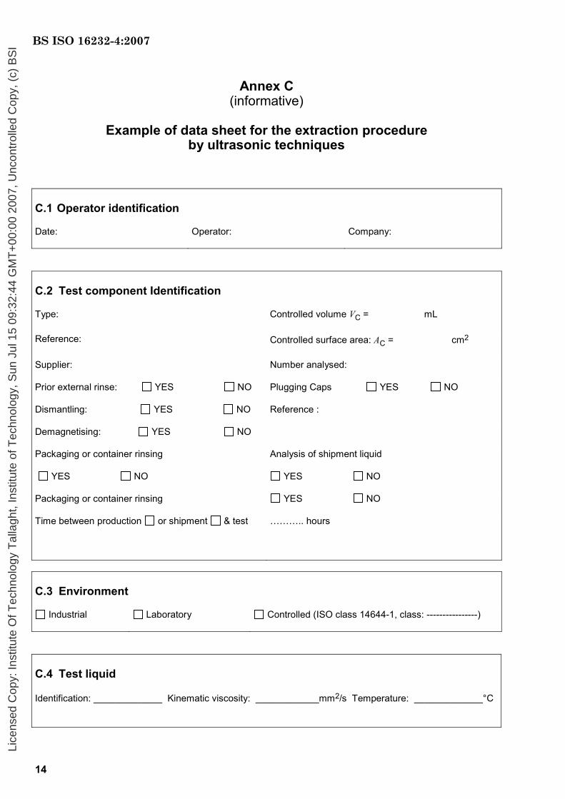
Annex C (informative)
Example of data sheet for the extraction procedure
by ultrasonic techniques
C.1 Operator identification
Date: Operator: Company:
C.2 Test component Identification
Type: Controlled volume VC = mL
Reference: Controlled surface area: AC = cm2
Supplier: Number analysed:
Prior external rinse: YES NO
Dismantling: YES NO
Plugging Caps YES NO
Reference :
Demagnetising: YES NO
Packaging or container rinsing
YES NO
Analysis of shipment liquid
YES NO
Packaging or container rinsing YES NO
Time between production or shipment & test ……….. hours
C.3 Environment
Industrial Laboratory Controlled (ISO class 14644-1, class: ----------------)
C.4 Test liquid
Identification: _____________ Kinematic viscosity: ____________mm2/s Temperature: _____________°C
BS ISO 16232-4:2007
Lice
nsed
Cop
y: In
stitu
te O
f Tec
hnol
ogy
Tal
lagh
t, In
stitu
te o
f Tec
hnol
ogy,
Sun
Jul
15
09:3
2:44
GM
T+
00:0
0 20
07, U
ncon
trol
led
Cop
y, (
c) B
SI
15
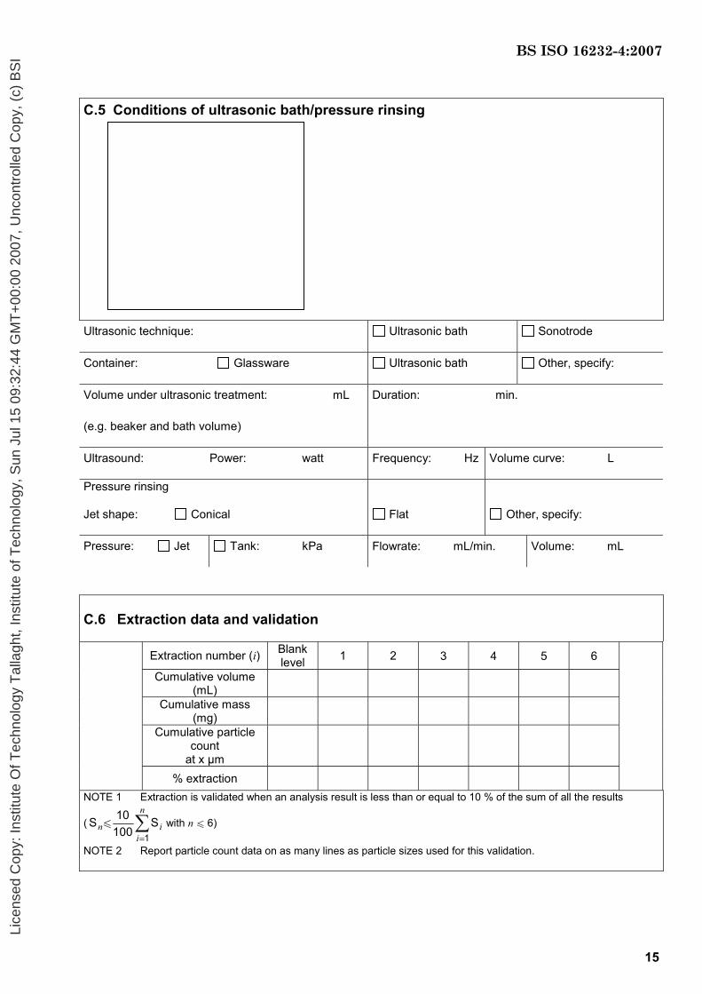
C.5 Conditions of ultrasonic bath/pressure rinsing Ultrasonic technique: Ultrasonic bath Sonotrode
Container: Glassware Ultrasonic bath Other, specify:
Volume under ultrasonic treatment: mL
(e.g. beaker and bath volume)
Duration: min.
Ultrasound: Power: watt Frequency: Hz Volume curve: L
Pressure rinsing
Jet shape: Conical
Flat
Other, specify:
Pressure: Jet Tank: kPa Flowrate: mL/min. Volume: mL
C.6 Extraction data and validation
Extraction number (i) Blank level 1 2 3 4 5 6
Cumulative volume (mL)
Cumulative mass (mg)
Cumulative particle count
at x µm
% extraction
NOTE 1 Extraction is validated when an analysis result is less than or equal to 10 % of the sum of all the results
(1
10S S100
n
n ii=∑u with n u 6)
NOTE 2 Report particle count data on as many lines as particle sizes used for this validation.
BS ISO 16232-4:2007
Lice
nsed
Cop
y: In
stitu
te O
f Tec
hnol
ogy
Tal
lagh
t, In
stitu
te o
f Tec
hnol
ogy,
Sun
Jul
15
09:3
2:44
GM
T+
00:0
0 20
07, U
ncon
trol
led
Cop
y, (
c) B
SI

16
C.7 Illustrations (pictures or drawings to be inserted by the author of the report)
Figure C.7.1 — Diagram or view in 2D
or 3D of the component
Figure C.7.2 — Position of the component in
the ultrasonic bath
Figure C.7.3 — Relative position of the
spray nozzle and the component during rinsing
Figure C.7.4 — Schematic of the spray
nozzle with dimensions
C.8 Detailed description of the extraction protocol
(Write a precise sequential list of the functions performed and the conditions of operation of the component before and during the sampling operation.)
BS ISO 16232-4:2007
Lice
nsed
Cop
y: In
stitu
te O
f Tec
hnol
ogy
Tal
lagh
t, In
stitu
te o
f Tec
hnol
ogy,
Sun
Jul
15
09:3
2:44
GM
T+
00:0
0 20
07, U
ncon
trol
led
Cop
y, (
c) B
SI

17
Annex D (informative)
Synopsis of the routine test procedure
Figure D.1 — Synopsis of the test procedure
Validated extraction procedure (6.2)
Conditioning of the equipment (6.2.9; 6.2.10)
Blank (6.3.3)
u 10 %
Test item and, if necessary, container of the component, shipment liquid (6.4.1)
Extraction of particles (6.4.1; 6.4.2)
Analysis of contaminants (7)
Presentation of the results (8)
Why
no
yes
BS ISO 16232-4:2007
Lice
nsed
Cop
y: In
stitu
te O
f Tec
hnol
ogy
Tal
lagh
t, In
stitu
te o
f Tec
hnol
ogy,
Sun
Jul
15
09:3
2:44
GM
T+
00:0
0 20
07, U
ncon
trol
led
Cop
y, (
c) B
SI
18
Bibliography
[1] ISO 14644-1, Cleanrooms and associated controlled environments — Part 1: Classification of air cleanliness
[2] ISO 18413, Hydraulic fluid power — Cleanliness of parts and components — Inspection document and principles related to contaminant collection, analysis and data reporting
[3] NF E 48-651, Hydraulic fluid power — Fluids — Determination of particulate contamination by the counting method using a microscope
[4] NF E 48-652, Hydraulic fluid power — Fluids — Determination of overall particulate contamination by the gravimetric method
[5] NF E 48-657, Cleanliness of components — Cleaning — Conditioning
[6] NF E 48-658, Hydraulic fluid power — Fluids — Determination of particulate contamination by automatic counting using the light interruption principle
[7] NF E 48-660, Hydraulic fluid systems — Fluids — Determination of solid particulate contamination by optical microscope and image analysis
BS ISO 16232-4:2007
Lice
nsed
Cop
y: In
stitu
te O
f Tec
hnol
ogy
Tal
lagh
t, In
stitu
te o
f Tec
hnol
ogy,
Sun
Jul
15
09:3
2:44
GM
T+
00:0
0 20
07, U
ncon
trol
led
Cop
y, (
c) B
SI

blank
Lice
nsed
Cop
y: In
stitu
te O
f Tec
hnol
ogy
Tal
lagh
t, In
stitu
te o
f Tec
hnol
ogy,
Sun
Jul
15
09:3
2:44
GM
T+
00:0
0 20
07, U
ncon
trol
led
Cop
y, (
c) B
SI
BS ISO 16232-4:2007
BSI389 Chiswick High RoadLondonW4 4AL
BSI — British Standards InstitutionBSI is the independent national body responsible for preparing British Standards. It presents the UK view on standards in Europe and at the international level. It is incorporated by Royal Charter.
Revisions
British Standards are updated by amendment or revision. Users of British Standards should make sure that they possess the latest amendments or editions.
It is the constant aim of BSI to improve the quality of our products and services. We would be grateful if anyone finding an inaccuracy or ambiguity while using this British Standard would inform the Secretary of the technical committee responsible, the identity of which can be found on the inside front cover. Tel: +44 (0)20 8996 9000. Fax: +44 (0)20 8996 7400.
BSI offers members an individual updating service called PLUS which ensures that subscribers automatically receive the latest editions of standards.
Buying standards
Orders for all BSI, international and foreign standards publications should be addressed to Customer Services. Tel: +44 (0)20 8996 9001. Fax: +44 (0)20 8996 7001. Email: [email protected]. Standards are also available from the BSI website at http://www.bsi-global.com.
In response to orders for international standards, it is BSI policy to supply the BSI implementation of those that have been published as British Standards, unless otherwise requested.
Information on standards
BSI provides a wide range of information on national, European and international standards through its Library and its Technical Help to Exporters Service. Various BSI electronic information services are also available which give details on all its products and services. Contact the Information Centre. Tel: +44 (0)20 8996 7111. Fax: +44 (0)20 8996 7048. Email: [email protected].
Subscribing members of BSI are kept up to date with standards developments and receive substantial discounts on the purchase price of standards. For details of these and other benefits contact Membership Administration. Tel: +44 (0)20 8996 7002. Fax: +44 (0)20 8996 7001. Email: [email protected].
Information regarding online access to British Standards via British Standards Online can be found at http://www.bsi-global.com/bsonline.
Further information about BSI is available on the BSI website at http://www.bsi-global.com.
Copyright
Copyright subsists in all BSI publications. BSI also holds the copyright, in the UK, of the publications of the international standardization bodies. Except as permitted under the Copyright, Designs and Patents Act 1988 no extract may be reproduced, stored in a retrieval system or transmitted in any form or by any means – electronic, photocopying, recording or otherwise – without prior written permission from BSI.
This does not preclude the free use, in the course of implementing the standard, of necessary details such as symbols, and size, type or grade designations. If these details are to be used for any other purpose than implementation then the prior written permission of BSI must be obtained.
Details and advice can be obtained from the Copyright & Licensing Manager. Tel: +44 (0)20 8996 7070. Fax: +44 (0)20 8996 7553. Email: [email protected].
Lice
nsed
Cop
y: In
stitu
te O
f Tec
hnol
ogy
Tal
lagh
t, In
stitu
te o
f Tec
hnol
ogy,
Sun
Jul
15
09:3
2:44
GM
T+
00:0
0 20
07, U
ncon
trol
led
Cop
y, (
c) B
SI