Embed Size (px)
Citation preview

Actuators & Sensors in Mechatronics:Brushless DC Motors
K. Craig1
Brushless Direct-Current Motors
• Features Common to Rotating Magnetic Field Electromechanical Devices– Introduction
– Windings
– Air Gap mmf – Sinusoidally-Distributed Windings
– Rotating Air Gap mmf – Two-Pole Devices
• Introduction to Several Electromechanical Motion Devices– Reluctance Devices
– Induction Machines

Actuators & Sensors in Mechatronics:Brushless DC Motors
K. Craig2
– Synchronous Machines
– Permanent-Magnet Devices
• Brushless DC Motors– Introduction
– Two-Phase Permanent-Magnet Synchronous Machine
– Voltage Equations and Winding Inductances
– Torque
– Machine Equations in the Rotor Reference Frame
– Time-Domain Block Diagrams and State Equations

Actuators & Sensors in Mechatronics:Brushless DC Motors
K. Craig3
Features Common to Rotating Magnetic Field Electromechanical Devices
• Introduction– A dc machine has windings on both the stationary and
rotating members, and these circuits are in relative motion whenever the armature (rotor) rotates. However, due to the action of the commutator, the resultant mmf produced by currents flowing in the rotor windings is stationary.
– The rotor windings appear to be stationary, magnetically.
– With constant current in the field (stator) winding, torque is produced and rotation results owing to the force established to align two stationary, orthogonal magnetic fields.

Actuators & Sensors in Mechatronics:Brushless DC Motors
K. Craig4
– In rotational electromechanical devices other than dcmachines, torque is produced as a result of one or more magnetic fields which rotate about the air gap of the device.
– Reluctance machines, induction machines, synchronous machines, stepper motors, and brushless dc motors (permanent-magnet synchronous machines), all develop torque in this manner.
– There are features of these devices which are common to all, in particular:
• Winding arrangement of the stator
• Method of producing a rotating magnetic field due to stator currents
– Hence, we cover these common features now.
Actuators & Sensors in Mechatronics:Brushless DC Motors
K. Craig5
• Windings– Consider the diagram of the elementary two-pole, single-
phase stator winding.
– Winding as is assumed distributed in slots over the inner circumference of the stator, which is more characteristic of the stator winding than is a concentrated winding.
– The winding is depicted as a series of individual coils. Each coil is placed in a slot in the stator steel.
– Follow the path of positive current ias flowing in the aswinding.
– Note that as1 and as1´ are placed in stator slots which span πradians; this is characteristic of a two-pole machine.
– as1 around to as1´ is referred to as a coil; as1 or as1´ is a coil side. In practice a coil will contain more than one conductor.

Actuators & Sensors in Mechatronics:Brushless DC Motors
K. Craig6
– The number of conductors in a coil side tells us the number of turns in this coil. This number is denoted as ncs.
– Repeat this winding process to form the as2 – as2´ coil and the as3 – as3´ coil, assuming that the same number of turns, ncs, make up each coil.
– With the same number of turns in each of these coils, the winding is said to be distributed over a span from as1 to as3
or 60°.
– The right-hand rule is used to give meaning to the as axis; it is the principal direction of magnetic flux established by positive current flowing in the as winding. It is said to denote the positive direction of the magnetic axis of the aswinding.

Actuators & Sensors in Mechatronics:Brushless DC Motors
K. Craig7
Elementary Two-Pole, Single-Phase Stator Winding

Actuators & Sensors in Mechatronics:Brushless DC Motors
K. Craig8
– Now, consider the diagram of the elementary two-pole, two-phase stator windings. Here we have added a second winding – the bs winding.
– The magnetic axis of the bs winding is displaced ½ π from that of the as winding.
– Assume that the positive direction of ibs is such that the positive magnetic axis of the bs winding is at φs = ½ πwhere φs is the angular displacement about the stator referenced to the as axis.
– This is the stator configuration for a two-pole, two-phase electromechanical device.
– The stator windings are said to be symmetrical (as it is used in electromechanical devices) if the number of turns per coil and resistance of the as and bs windings are identical.

Actuators & Sensors in Mechatronics:Brushless DC Motors
K. Craig9
– For a two-pole, three-phase, symmetrical electromechanical device, there are three identical stator windings displaced 120° from each other. Essentially all multiphase electromechanical devices are equipped with symmetrical stators.

Actuators & Sensors in Mechatronics:Brushless DC Motors
K. Craig10
Elementary Two-Pole, Two-Phase Stator Windings

Actuators & Sensors in Mechatronics:Brushless DC Motors
K. Craig11
• Air Gap mmf – Sinusoidally-Distributed Windings– It is generally assumed that the stator windings (and in
many cases the rotor windings) may be approximated as sinusoidally-distributed windings.
– The distribution of a stator phase winding may be approximated as a sinusoidal function of φs, and the waveform of the resulting mmf dropped across the air gap (air gap mmf) of the device may also be approximated as a sinusoidal function of φs.
– To establish a truly sinusoidal air gap mmf, the winding must also be distributed sinusoidally, and it is typically assumed that all windings may be approximated as sinusoidally-distributed windings.

Actuators & Sensors in Mechatronics:Brushless DC Motors
K. Craig12
– In the figure, we have added a few coils to the as winding, which now span 120°.
– For the purpose of establishing an expression for the air gap mmf, we employ the developed diagram of the cross-sectional view obtained by “flattening out” the rotor and stator.
– Note that displacement φs is defined to the left of the asaxis since this allows us to position the stator above the rotor.
– The winding distributions may be approximated as:
– Np is the peak turns density in turns/radian.
as p s s
as p s s
N N sin for 0
N N sin for 2
= φ < φ < π
= − φ π < φ < π

Actuators & Sensors in Mechatronics:Brushless DC Motors
K. Craig13
– If Ns represents the number of turns of the equivalent sinusoidally distributed winding (not the total turns of the winding) that corresponds to the fundamental component of the actual winding distribution, then:
– The sinusoidally-distributed winding will produce a mmf that is positive in the direction of the as axis (to the right in the figure for positive ias).
– We assume that all of the mmf is dropped across the air gap, as the reluctance of the steel is much smaller (neglecting saturation) than the reluctance of the air gap.
– So if the windings are sinusoidally-distributed in space, then the mmf dropped across the air gap will also be sinusoidal in space.
( )s p s s p0N N sin d 2N
π
= φ φ =∫

Actuators & Sensors in Mechatronics:Brushless DC Motors
K. Craig14
Approximate Sinusoidal Distribution of the as Winding

Actuators & Sensors in Mechatronics:Brushless DC Motors
K. Craig15
Developed Diagram withSinusoidally-Distributed Stator Winding
Stator
Rotor

Actuators & Sensors in Mechatronics:Brushless DC Motors
K. Craig16
– We need to develop an expression for the air gap mmf, mmfas, associated with the as winding. We will apply Ampere’s Law to two closed paths, shown in the diagram.
– For closed path (a), the total current enclosed is Nsias and, by Ampere’s Law, this is equal to the mmf drop around the given path ( ).
– If the reluctance of the rotor and stator steel is small compared with the air-gap reluctance, we can assume that ½ of the mmf is dropped across the air gap at φs = 0 and ½at φs = π.
– By definition mmfas is positive for a mmf drop across the air gap from the rotor to the stator. Thus mmfas is positive at φs = 0 and negative at φs = π, assuming positive ias.
H dL∫ur uur
iÑ

Actuators & Sensors in Mechatronics:Brushless DC Motors
K. Craig17
– This suggests that for arbitrary φs, mmfas might be expressed as:
– This tells that the air gap mmf is zero at φs = ± ½ π. Check this by applying Ampere’s Law to the second closed path in the figure, path (b). The net current enclosed is zero, and so the mmf drop is zero along the given path, implying that mmfas = 0 at φs = ± ½ π.
sas as s
Nmmf i cos
2= φ
( )
( )
sas as
sas as
Nmmf 0 i
2N
mmf i2
=
π = −

Actuators & Sensors in Mechatronics:Brushless DC Motors
K. Craig18
– Let’s consider the bs winding of a two-phase device. The air gap mmf due to a sinusoidally-distributed bs winding may be expressed as:
sbs bs s
Nmmf i sin
2= φ

Actuators & Sensors in Mechatronics:Brushless DC Motors
K. Craig19
Closed Paths used to Establish mmfas

Actuators & Sensors in Mechatronics:Brushless DC Motors
K. Craig20
A mmfas Due to Sinusoidally Distributed as Winding

Actuators & Sensors in Mechatronics:Brushless DC Motors
K. Craig21
• Rotating Air Gap mmf – Two-Pole Devices– Considerable insight into the operation of
electromechanical motion devices can be gained from an analysis of the air gap mmf produced by current flowing in the stator winding(s).
– Let’s consider the rotating air gap mmf’s produced by currents flowing in the stator windings of single-, two-, and three-phase devices.

Actuators & Sensors in Mechatronics:Brushless DC Motors
K. Craig22
• Single-Phase Devices– Consider the device shown which illustrates a single-phase
stator winding. Assume the as winding is sinusoidally distributed, with as and as´ placed at the point of maximum turns density.
– Assume that the current flowing in the as winding is a constant. Then the as winding would establish a stationary magnetic system with a N pole from 0.5π < φs < 1.5π and a S pole from -0.5π < φs < 0.5π.
– The air gap mmf is directly related to these poles; indeed, the flux flowing from the N pole and into the S pole is caused by the air gap mmf.

Actuators & Sensors in Mechatronics:Brushless DC Motors
K. Craig23
Elementary Two-Pole, Single-Phase Sinusoidally-Distributed Stator Winding

Actuators & Sensors in Mechatronics:Brushless DC Motors
K. Craig24
– What happens when the current flowing in the as winding is a sinusoidal function of time? Let’s assume steady-state operation:
– Capital letters denote steady-state instantaneous variables; Is is the rms value of the current; ωe is the electrical angular velocity; θesi(0) is the angular position corresponding to the time zero value of the instantaneous current.
– The air gap mmf expressed for the as winding is:
( )as s e esiI 2I cos t 0 = ω + θ
( )s sas as s s e esi s
N Nmmf i cos 2I cos t 0 cos
2 2 = φ = ω + θ φ
Actuators & Sensors in Mechatronics:Brushless DC Motors
K. Craig25
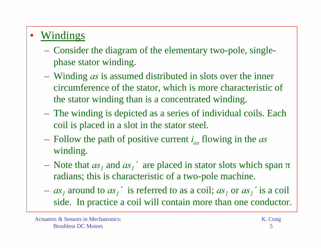
– Consider this expression for a moment. It appears that all we have here is a stationary, pulsating magnetic field. Let us rewrite this expression using a trig identity:
– The arguments of the cosine terms are functions of time and displacement φs. If we can make an argument constant, then the cosine of this argument would be constant.
– What does this mean?
( ) ( )sas s e esi s e esi s
N 1 1mmf 2I cos t 0 cos t 0
2 2 2
= ω + θ − φ + ω + θ + φ
( )
( )e esi s 1
e esi s 2
t 0 C
t 0 C
ω + θ − φ =
ω + θ + φ =
se
se
d
dtd
dt
φ= ω
φ= − ω

Actuators & Sensors in Mechatronics:Brushless DC Motors
K. Craig26
– If you run around the air gap in CCW direction at an angular velocity ωe, the first term in the expression for mmfas will appear as a constant mmf and hence a constant set of N and S poles. On the other hand, if we run CW at ωe, the second term in the expression for mmfas will appear as a constant mmf.
– In other words, the pulsating air gap mmf we noted standing at φs = 0 (or any fixed value of φs) can be thought of as two, one-half amplitude, oppositely-rotating air gap mmf’s (magnetic fields), each rotating at the angular speed of ωe, which is the electrical angular velocity of the current.
– Since we have two oppositely rotating sets of N and S poles (magnetic fields), it would seem that the single-phase machine could develop an average torque as a result of interacting with either.

Actuators & Sensors in Mechatronics:Brushless DC Motors
K. Craig27
– A single-phase electromechanical device with the stator winding as shown can develop an average torque in either direction of rotation.
– Note that this device is a two-pole device, even though there are two two-pole sets, as only one set interacts with the rotor to produce a torque with a nonzero average.

Actuators & Sensors in Mechatronics:Brushless DC Motors
K. Craig28
• Two-Phase Devices– Consider the two-pole, two-phase sinusoidally distributed
stator windings shown.
– For balanced (i.e., variables are equal-amplitude sinusoidal quantities and 90° out of phase) steady-state conditions, the stator currents may be expressed as:
– The reason for selecting this set of stator currents will become apparent.
– The total air gap mmf due to both stator windings (assumed to be sinusoidally distributed) may be expressed by adding mmfas and mmfbs to give mmfs.
( )
( )
as s e esi
bs s e esi
I 2I cos t 0
I 2I sin t 0
= ω + θ
= ω + θ

Actuators & Sensors in Mechatronics:Brushless DC Motors
K. Craig29
– The total air gap mmf due to the stator windings is:
– Substitution:
– Result:
sas as s
Nmmf i cos
2= φ
sbs bs s
Nmmf i sin
2= φ
( )ss as s bs s
Nmmf i cos i sin
2= φ + φ
( )
( )
as s e esi
bs s e esi
I 2I cos t 0
I 2I sin t 0
= ω + θ
= ω + θ
( )ss as s bs s
Nmmf i cos i sin
2= φ + φ
( )ss s e esi s
Nmmf 2I cos t 0
2 = ω + θ − φ

Actuators & Sensors in Mechatronics:Brushless DC Motors
K. Craig30
Elementary Two-Pole, Two-Phase Sinusoidally-Distributed Stator Winding
Actuators & Sensors in Mechatronics:Brushless DC Motors
K. Craig31
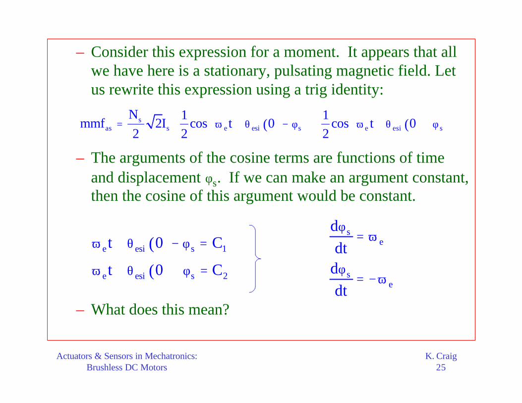
– It is interesting to note that we have only one rotating air gap mmf or rotating magnetic field.
– Set the argument equal to a constant, take the derivative with respect to time, and we find that the argument is constant if
– If we travel around the air gap in the CCW direction at ωe, we will always see a constant mmfs for the balanced set of currents
– Hence a single rotating air gap mmf is produced. The actual value that we would see as we travel around the air gap at ωe would depend upon the selection of time zero and our position on the stator at time zero.
se
d
dt
φ= ω
( )
( )
as s e esi
bs s e esi
I 2I cos t 0
I 2I sin t 0
= ω + θ
= ω + θ

Actuators & Sensors in Mechatronics:Brushless DC Motors
K. Craig32
– With the assigned positive direction of current in the given arrangement of the as and bs windings shown, the balanced set of stator currents produces a mmfs that rotates CCW, which is desired for conventional purposes.
– In the case of the single-phase stator winding with a sinusoidal current, the air gap mmf can be thought of as two oppositely-rotating, constant-amplitude mmf’s. However, the instantaneous air gap mmf is pulsating even when we are traveling with one of the rotating air gap mmf’s. Unfortunately, this pulsating air gap mmf or set of poles gives rise to steady-state pulsating components of electromagnetic torque.
Actuators & Sensors in Mechatronics:Brushless DC Motors
K. Craig33
– In the case of the two-phase stator with balanced currents, only one rotating air gap mmf exists. Hence, the steady-state electromagnetic torque will not contain a pulsating or time-varying component; it will be a constant with the value determined by the operating conditions.

Actuators & Sensors in Mechatronics:Brushless DC Motors
K. Craig34
• Three-Phase Devices– The stator windings of a two-pole, three-phase device are
shown in the figure.
– The windings are identical, sinusoidally distributed with Ns
equivalent turns and with their magnetic axes displaced 120°; the stator is symmetrical.
– The positive direction of the magnetic axes is selected so as to achieve counterclockwise (CCW) rotation of the rotating air gap mmf with balanced stator currents of the abcsequence.

Actuators & Sensors in Mechatronics:Brushless DC Motors
K. Craig35
– The air gap mmf’s established by the stator windings may be expressed by inspection as:
– As before, Ns is the number of turns of the equivalent sinusoidally distributed stator windings and φs is the angular displacement about the stator.
sas as s
sbs bs s
scs cs s
Nmmf i cos
2N 2
mmf i cos2 3
N 2mmf i cos
2 3
= φ
= φ − π
= φ + π

Actuators & Sensors in Mechatronics:Brushless DC Motors
K. Craig36
ElementaryTwo-Pole,
Three-Phase Sinusoidally-
Distributed Stator Windings

Actuators & Sensors in Mechatronics:Brushless DC Motors
K. Craig37
– For balanced steady-state conditions, the stator currents for an abc sequence may be expressed as:
– Substitution:
( )
( )
( )
as s e esi
bs s e esi
cs s e esi
I 2I cos t 0
2I 2I cos t 0
3
2I 2I cos t 0
3
= ω + θ
= ω − π + θ
= ω + π + θ
( )
( )
( )
as s e esi
bs s e esi
cs s e esi
I 2I cos t 0
2I 2I cos t 0
3
2I 2I cos t 0
3
= ω + θ
= ω − π + θ
= ω + π + θ
sas as s
sbs bs s
scs as s
Nmmf i cos
2N 2
mmf i cos2 3
N 2mmf i cos
2 3
= φ
= φ − π
= φ + π

Actuators & Sensors in Mechatronics:Brushless DC Motors
K. Craig38
– Add the resulting expressions to yield an expression for the rotating air gap mmf established by balanced steady-state currents flowing in the stator windings:
– Compare this with the mmfs for a two-phase device:
– They are identical except that the amplitude of the mmf for the 3-phase device is 3/2 times that of a 2-phase device.
( )ss s e esi s
N 3mmf 2I cos t 0
2 2 = ω + θ − φ
( )ss s e esi s
Nmmf 2I cos t 0
2 = ω + θ − φ
3-Phase
2-Phase
( )ss s e esi s
N 3mmf 2I cos t 0
2 2 = ω + θ − φ

Actuators & Sensors in Mechatronics:Brushless DC Motors
K. Craig39
– It can be shown that this amplitude for multiphase devices changes from that of a two-phase device in proportion to the number of phases divided by 2.
– It is important to note that with the selected positive directions of the magnetic axes a counterclockwise rotating air gap mmf is obtained with a three-phase set of balanced stator currents of the abc sequence.

Actuators & Sensors in Mechatronics:Brushless DC Motors
K. Craig40
Introduction to Several Electromechanical Motion Devices
• Rotational electromechanical devices fall into three general classes:– Direct-current
– Synchronous
– Induction
• We have already covered dc machines.
• Synchronous Machines– They are so called because they develop an average torque
only when the rotor is rotating in synchronism (synchronous speed) with the rotating air gap mmf established by currents flowing in the stator windings.

Actuators & Sensors in Mechatronics:Brushless DC Motors
K. Craig41
– Examples are: reluctance machines, stepper motors, permanent-magnet machines, brushless dc machines, and the machine which has become known as simply the synchronous machine.
• Induction Machines– Induction is the principle means of converting energy from
electrical to mechanical.
– The induction machine cannot develop torque at synchronous speed in its normal mode of application.
– The windings on the rotor are short-circuited and, in order to cause current to flow in these windings which produce torque by interacting with the air gap mmf established by the stator windings, the rotor must rotate at a speed other than synchronous speed.

Actuators & Sensors in Mechatronics:Brushless DC Motors
K. Craig42
• Here we will show the winding arrangement for elementary versions of these electromechanical devices and describe briefly the principle of operation of each.

Actuators & Sensors in Mechatronics:Brushless DC Motors
K. Craig43
• Reluctance Drives– Elementary single-, and two-phase two-pole reluctance
machines are shown in the figure.
– Stator windings are assumed to be sinusoidally distributed.
– The principal of operation is quite straightforward.• In an electromagnetic system a force (torque) is produced in an
attempt to minimize the reluctance of the magnetic system.
• We have established that, with an alternating current flowing in the winding of the single-phase stator, two oppositely-rotating mmf’s are produced.
• Therefore, once the rotor is rotating in synchronism with either of the two oppositely-rotating air gap mmf’s, there is a force (torque) created by the magnetic system in an attempt to align the minimum-reluctance path of the rotor with the rotating air gap mmf.

Actuators & Sensors in Mechatronics:Brushless DC Motors
K. Craig44
• When there is no load torque on the rotor, the minimum-reluctance path of the rotor is in alignment with the rotating air gap mmf.
• When a load torque is applied, the rotor slows ever so slightly,thereby creating a misalignment of the minimum-reluctance path and the rotating air gap mmf.
• When the electromagnetic torque produced in an attempt to maintain alignment is equal and opposite to the load torque on the rotor, the rotor resumes synchronous speed.
• If the load torque is larger than the torque which can be produced to align, the rotor will fall out of synchronism and, since the machine cannot develop an average torque at a speed other than synchronous, it will slow to stall.
• The operation of a two-phase device differs from that of the single-phase device in that only one constant-amplitude rotating air gap mmf is produced during balanced steady-state conditions.
• Hence, a constant torque will be developed at synchronous speed rather than a torque which pulsates about an average value as is the case with the single-phase machine.

Actuators & Sensors in Mechatronics:Brushless DC Motors
K. Craig45
• Although the reluctance motor can be started from a source whichcan be switched at a frequency corresponding to the rotor speed as in the case of stepper or brushless dc motors, the devices cannot develop an average starting torque when plugged into a householdpower outlet.
• Many stepper motors are of the reluctance type. Some stepper motors are called variable-reluctance motors. Operation is easily explained. Assume that a constant current is flowing the bswinding of the figure with the as winding open-circuited. The minimum reluctance path of the rotor will be aligned with the bsaxis, i.e., assume θr is zero. Now let’s reduce the bs winding current to zero while increasing the current in the as winding to a constant value. There will be forces to align the minimum-reluctance path of the rotor with the as axis; however, this can be satisfied with θr = ± ½ π. There is a 50-50 chance as to which way it will rotate. We see that we need a device different from a single-or two-phase reluctance machine to accomplish controlled stepping. Two common techniques are single-stack and multistack variable-reluctance steppers.

Actuators & Sensors in Mechatronics:Brushless DC Motors
K. Craig46
Elementary Two-Pole Reluctance Machines:Single-Phase and Two-Phase

Actuators & Sensors in Mechatronics:Brushless DC Motors
K. Craig47
• Induction Machines– Elementary single- and two-phase induction machines are
shown in the figure.
– The rotors of both devices are identical in configuration; each has the equivalent of two orthogonal windings which are assumed to be sinusoidally distributed. The ar and br windings are equivalent to a symmetrical two-phase set of windings and, in the vast majority of applications, these rotor windings are short-circuited.
– Let’s look at the operation of the two-phase device first.• For balanced steady-state operation, the currents flowing in the
stator windings produce an air gap mmf which rotates about the air gap at an angular velocity of ωe.

Actuators & Sensors in Mechatronics:Brushless DC Motors
K. Craig48
• With the rotor windings short-circuited, which is the only mode of operation we will consider, a voltage is induced in each of the rotor windings only if the rotor speed ωr is different from ωe.
• The currents flowing in the rotor circuits due to induction will be a balanced set with a frequency equal to ωe- ωr, which will produce an air gap mmf that rotates at ωe- ωr relative to the rotor or ωe
relative to a stationary observer.
• Hence, the rotating air gap mmf caused by the currents flowing in the stator windings induces currents in the short-circuited rotor windings which, in turn, establish an air gap mmf that rotates in unison with the stator rotating air gap mmf (mmfs).
• Interaction of these magnetic systems (poles) rotating in unisonprovides the means of producing torque on the rotor.
• An induction machine can operate as a motor or a generator. However, it is normally operated as a motor.

Actuators & Sensors in Mechatronics:Brushless DC Motors
K. Craig49
• As a motor it can develop torque from 0 < ωr < ωe. At ωr = ωe, the rotor currents are not present since the rotor is rotating at the speed of the stator rotating air gap mmf and, therefore, the rotor windings do not experience a change of flux linkages, which is, of course, necessary to induce a voltage in the rotor windings.
• The single-phase induction motor is perhaps the most widely used electromechanical device. The figure shown is not quite the whole picture of a single-phase induction motor. Recall that the single-phase stator winding produces oppositely rotating air gap mmf’s of equal amplitude.
• If the single-phase induction motor is stalled, ωr = 0, and if a sinusoidal current is applied to the stator winding, the rotor will not move. This device does not develop a starting torque. Why?
• The rotor cannot follow either of the rotating mmf’s since it develops as much torque to go with one as it does to go with theother. If, however, you manually turn the rotor in either direction, it will accelerate in that direction and operate normally.

Actuators & Sensors in Mechatronics:Brushless DC Motors
K. Craig50
• Although single-phase induction motors normally operate with only one stator winding, it is necessary to use a second stator winding to start the device. Actually single-phase induction motors we use are two-phase induction motors with provisions to switch out one of the windings once the rotor accelerates to between 60 and 80 percent of synchronous speed.
• How do we get two-phase voltages from a single-phase household supply? Well, we do not actually develop a two-phase supply, but we approximate one, as far as the two-phase motor is concerned, by placing a capacitor (start capacitor) in series with one of the stator windings. This shifts the phase of one current relative to the other, thereby producing a larger rotating air gap mmf in one directionthan the other. Provisions to switch the capacitor out of the circuit is generally inside the housing of the motor.

Actuators & Sensors in Mechatronics:Brushless DC Motors
K. Craig51
Elementary Two-Pole Induction Machines:Single-Phase and Two-Phase

Actuators & Sensors in Mechatronics:Brushless DC Motors
K. Craig52
• Synchronous Machines– Shown are elementary single- and two-phase two-pole
synchronous machines. However, they are but one of several devices which fall into the synchronous machine category. We honor convention here and refer to these devices as synchronous machines.
– The single-phase synchronous machine has limited application. The same can be said about the two-phase synchronous machine. It is the three-phase synchronous machine which is used to generate electric power in power systems such as in some automobiles, aircraft, utility systems, and ships. Nevertheless, the theory of operation of synchronous machines is adequately introduced by considering the two-phase version.

Actuators & Sensors in Mechatronics:Brushless DC Motors
K. Craig53
• The elementary devices shown have only one rotor winding – the field winding (f winding). In practical synchronous machines, the rotor is equipped with short-circuited windings in addition to the f winding which help to damp oscillations about synchronous speed and, in some cases, these windings are used to start the unloaded machine from stall as an induction motor.
• The principle of operation is apparent once we realize that the current flowing in the field winding is direct current. Although it may be changed in value by varying the applied field voltage, it is constant for steady-state operation of a balanced two-phase synchronous machine.
• If the stator windings are connected to a balanced system, the stator currents produce a constant-amplitude rotating air gap mmf. A rotor air gap mmf is produced by the direct current flowing in the field winding.
• To produce a torque or transmit power, the air gap mmf produced by the stator and that produced by the rotor must rotate in unison about the air gap of the machine. Hence, ωr = ωe.

Actuators & Sensors in Mechatronics:Brushless DC Motors
K. Craig54
Elementary Two-Pole Synchronous Machines:Single-Phase and Two-Phase

Actuators & Sensors in Mechatronics:Brushless DC Motors
K. Craig55
• Permanent-Magnet Devices– If we replace the rotor of the synchronous machines just
considered with a permanent-magnet rotor, we have the so-called permanent-magnet devices shown in the figure.
– The operation of these devices is identical to that of the synchronous machine.
– Since the strength of the rotor field due to the permanent magnet cannot be controlled as in the case of the synchronous machine which has a field winding, it is not widely used as a means of generating power.
– It is, however, used widely as a drive motor.

Actuators & Sensors in Mechatronics:Brushless DC Motors
K. Craig56
– In particular, permanent-magnet motors are used as stepper motors and, extensively, as brushless dc motors, wherein the voltages applied to the stator windings are switched electronically at a frequency corresponding to the speed of the rotor.

Actuators & Sensors in Mechatronics:Brushless DC Motors
K. Craig57
Elementary Two-Pole Permanent-Magnet Devices:Single-Phase and Two-Phase

Actuators & Sensors in Mechatronics:Brushless DC Motors
K. Craig58
Brushless DC Motors
• Introduction– Permanent magnet DC motors all have brushes to transmit
power to the armature windings. Brush arcing causes electronic noise and maintenance problems from excessive wear.
– A Brushless DC Motor has been developed to overcome these problems. It substitutes electronic commutation for the conventional mechanical brush commutation.
– Because the electronic commutation exactly duplicates the brush commutation in conventional DC motors, the brushless DC motor exhibits the same linear torque-speed curve, has the same motor constants, and obeys the same performance equations.

Actuators & Sensors in Mechatronics:Brushless DC Motors
K. Craig59
• Advantages of Brushless DC Motors– High Reliability
• The life of brushless DC motors is almost indefinite. Bearing failure is the most likely weak point.
– Quiet• A lack of mechanical noise from brushes makes it ideal for a
people environment. An added advantage is that there is no mechanical friction.
– High Speed• Brush bounce limits DC motors to 10,000 RPM. Brushless DC
motors have been developed for speeds up to 100,000 RPM, limited by the mechanical strength of the permanent magnet rotors.

Actuators & Sensors in Mechatronics:Brushless DC Motors
K. Craig60
– High Peak Torque• Brushless DC motors have windings on the stator housing. This
gives efficient cooling and allows for high currents (torque) during low-duty-cycle, stop-start operation. Peak torques are more than 20 times their steady ratings compared to 10 times or less for conventional DC motors. Maximum power per unit volume can be 5 times conventional DC motors.
• Disadvantages of Brushless DC Motors– Cost
• The relatively high cost of brushless DC motors is usually acceptable when considering complex machinery where normal downtime and maintenance are not only costly in itself, but often unacceptable.
– Choice• Choice is restricted because there are few manufacturers.

Actuators & Sensors in Mechatronics:Brushless DC Motors
K. Craig61
• Types of Brushless DC Motors– Windings on the stator with the rotor on the inside; inside
rotors have less inertia and are better suited for start-stop operation.
– Windings on the stator with the rotor on the outside; outside rotors are better for constant load, high-speed applications.

Actuators & Sensors in Mechatronics:Brushless DC Motors
K. Craig62
• The brushless dc motor is becoming widely used as a small-horsepower control motor. It is a permanent-magnet synchronous machine. When it is supplied from a source, the frequency of which is always equal to the speed of its rotor, it becomes a brushless dc motor, not because it looks like a dc motor but because its operating characteristics can be made to resemble those of a dc shunt motor with a constant field current.
• How do we supply the permanent-magnet synchronous machine from a source the frequency of which always corresponds to the rotor speed?

Actuators & Sensors in Mechatronics:Brushless DC Motors
K. Craig63
– First we must be able to measure the rotor position. The rotor position is most often sensed by Hall-effect sensors which magnetically sense the position of the rotor poles.
– Next we must make the frequency of the source correspond to the rotor speed. This is generally accomplished with a dc-to-ac inverter, wherein the transistors are switched on and off at a frequency corresponding to the rotor speed. We are able to become quite familiar with the operating features of the brushless dc motor without getting involved with the actual inverter.
– If we assume that the stator variables (voltages and currents) are sinusoidal and balanced with the same angular velocity as the rotor speed, we are able to predict the predominant operating features of the brushless dc motor without becoming involved with the details of the inverter.

Actuators & Sensors in Mechatronics:Brushless DC Motors
K. Craig64
• Two-Phase Permanent-Magnet Synchronous Machine– A two-pole two-phase permanent-magnet synchronous
machine is shown.
– The stator windings are identical, sinusoidally distributed windings each with Ns equivalent turns and resistance rs.
– The magnetic axes of the stator windings are as and bs axes.
– The angular displacement about the stator is denoted by φs, referenced to the as axis.
– The angular displacement about the rotor is φr, referenced to the q axis.
– The angular velocity of the rotor is ωr and θr is the angular displacement of the rotor measured from the as axis to the qaxis.
– Thus s r rφ = φ + θ

Actuators & Sensors in Mechatronics:Brushless DC Motors
K. Craig65
– The d axis (direct axis) is fixed at the center of the N pole of the permanent-magnet rotor and the q axis (quadrature axis) is displaced 90° CCW from the d axis.
– The electromechanical torque Te is assumed positive in the direction of increasing θr and the load torque TL is positive in the opposite direction.
– In the following analysis, it is assumed that:• The magnetic system is linear.
• The open-circuit stator voltages induced by rotating the permanent-magnet rotor at a constant speed are sinusoidal.
• Large stator currents can be tolerated without significant demagnetization of the permanent magnet.
• Damper windings (short-circuited rotor windings) are not considered. Neglecting damper windings, in effect, neglects currents circulating in the surface of the rotor (eddy currents).

Actuators & Sensors in Mechatronics:Brushless DC Motors
K. Craig66
– The two sensors shown are Hall-effect sensors. When the N pole is under a sensor, its output is nonzero; with a S pole under the sensor, its output is zero.
– In the brushless dc motor applications, the stator is supplied from a dc-to-ac inverter the frequency of which corresponds to the rotor speed.
– The states of the sensors are used to determine the switching logic for the inverter which, in turn, determines the output frequency of the inverter.
– In the actual machine, the sensors are not positioned over the rotor. Instead, they are placed over a ring which is mounted on the shaft external to stator windings and which is magnetized by the rotor.

Actuators & Sensors in Mechatronics:Brushless DC Motors
K. Craig67
– The electromagnetic torque is produced by the interaction of the poles of the permanent-magnet rotor and the poles resulting from the rotating air gap mmf established by currents flowing in the stator windings.
– The rotating mmf (mmfs) established by symmetrical two-phase stator windings carrying balanced two-phase currents is given by:
( )ss s e esi s
Nmmf 2I cos t 0
2 = ω + θ − φ

Actuators & Sensors in Mechatronics:Brushless DC Motors
K. Craig68
Two-Pole, Two-Phase Permanent-Magnet
Synchronous Machine
Actuators & Sensors in Mechatronics:Brushless DC Motors
K. Craig69
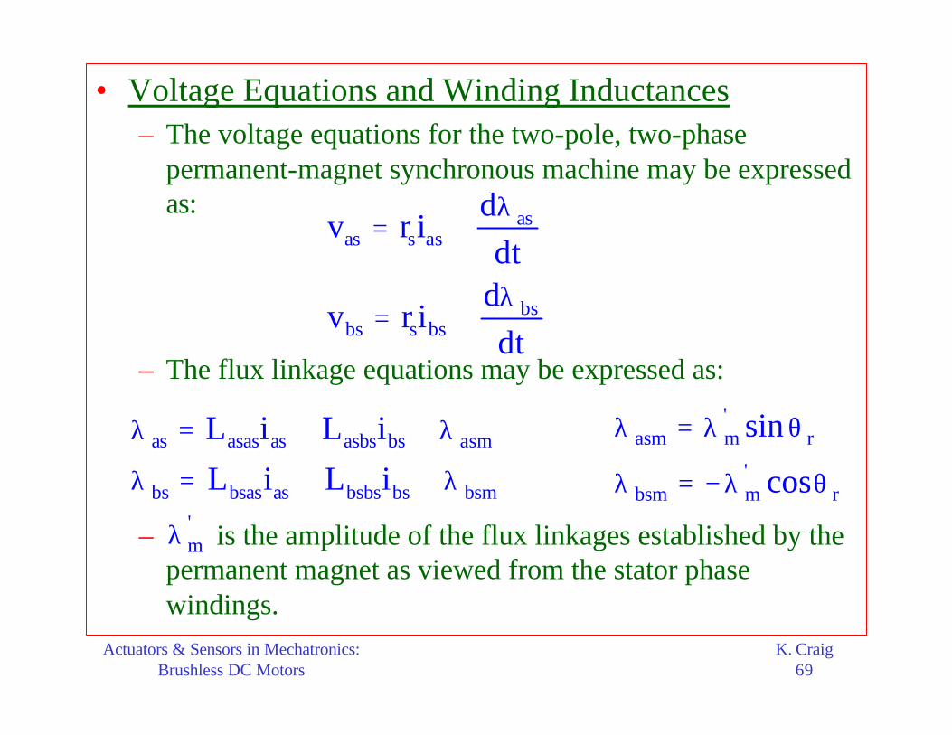
• Voltage Equations and Winding Inductances– The voltage equations for the two-pole, two-phase
permanent-magnet synchronous machine may be expressed as:
– The flux linkage equations may be expressed as:
– is the amplitude of the flux linkages established by the permanent magnet as viewed from the stator phase windings.
asas s as
bsbs s bs
dv r i
dtd
v r idt
λ= +
λ= +
as asas as asbs bs asm
bs bsas as bsbs bs bsm
L i L i
L i L i
λ = + + λ
λ = + + λ
'asm m r
'bsm m r
sin
cos
λ = λ θ
λ = − λ θ'mλ

Actuators & Sensors in Mechatronics:Brushless DC Motors
K. Craig70
– In other words, the magnitude of is proportional to the magnitude of the open-circuit sinusoidal voltage induced in each stator phase winding. Visualize the permanent-magnet rotor as a rotor with a winding carrying a constant current and in such a position to cause the N and S poles to appear as shown in the diagram.
– Assume that the air gap of the permanent-magnet synchronous machine is uniform. This may be an oversimplification.
– With this assumption of uniform air gap, the mutual inductance between the as and bs windings is zero.
– Since the windings are identical, the self-inductances Lasas
and Lbsbs are equal and denoted as Lss.
'mλ

Actuators & Sensors in Mechatronics:Brushless DC Motors
K. Craig71
– The self-inductance is made up of a leakage and a magnetizing inductance:
– The machine is designed to minimize the leakage inductance; it generally makes up approximately 10% of Lss. The magnetizing inductances may be expressed in terms of turns and reluctance:
– The magnetizing reluctance ℜm is an equivalent reluctance due to the stator steel, the permanent magnet, and the air gap. Assume that it is independent of rotor position θr.
ss s msL L L= +l
2s
msm
NL =
ℜ

Actuators & Sensors in Mechatronics:Brushless DC Motors
K. Craig72
• Torque– An expression for the electromagnetic torque may be
obtained from:
– The co-energy Wc may be expressed as:
– Where Wpm relates to the energy associated with the permanent magnet, which is constant for the device under consideration.
( )( )c
e
W i,T i,
∂ θθ =
∂θ
rr
( )2 2 ' 'c ss as bs m as r m bs r pm
1W L i i i sin i cos W
2= + + λ θ − λ θ +

Actuators & Sensors in Mechatronics:Brushless DC Motors
K. Craig73
– Taking the partial derivative with respect to θr yields:
– This expression is positive for motor action. The torque and speed may be related as:
( )( )
( )c '
e m as r bs r
W i, PT i, i cos i sin
2
∂ θθ = = λ θ + θ
∂θ
rr
re m r L
2 d 2T J B T
P dt P
ω = + ω +

Actuators & Sensors in Mechatronics:Brushless DC Motors
K. Craig74
• Machine Equations in the Rotor Reference Frame– A change of variables is helpful in the analysis of the
permanent-magnet synchronous machine.
– The objective of a change of variables is to transform all machine variables to a common reference frame, thereby eliminating θr from the inductance equations.
– But the inductance Lss is not a function of θr. However the flux linkages Lasm and Lbsm are functions of θr. In other words, the magnetic system of the permanent magnet is viewed as a time-varying flux linkage by the stator windings.
– For a two-phase system the transformation is: r
asr rqsr
bsr rds
fcos sinf
fsin cosf
θ θ = θ − θ
r rqds s absf K f=
1r r r rabs s qds s qdsf K f K f
− = =
Actuators & Sensors in Mechatronics:Brushless DC Motors
K. Craig75
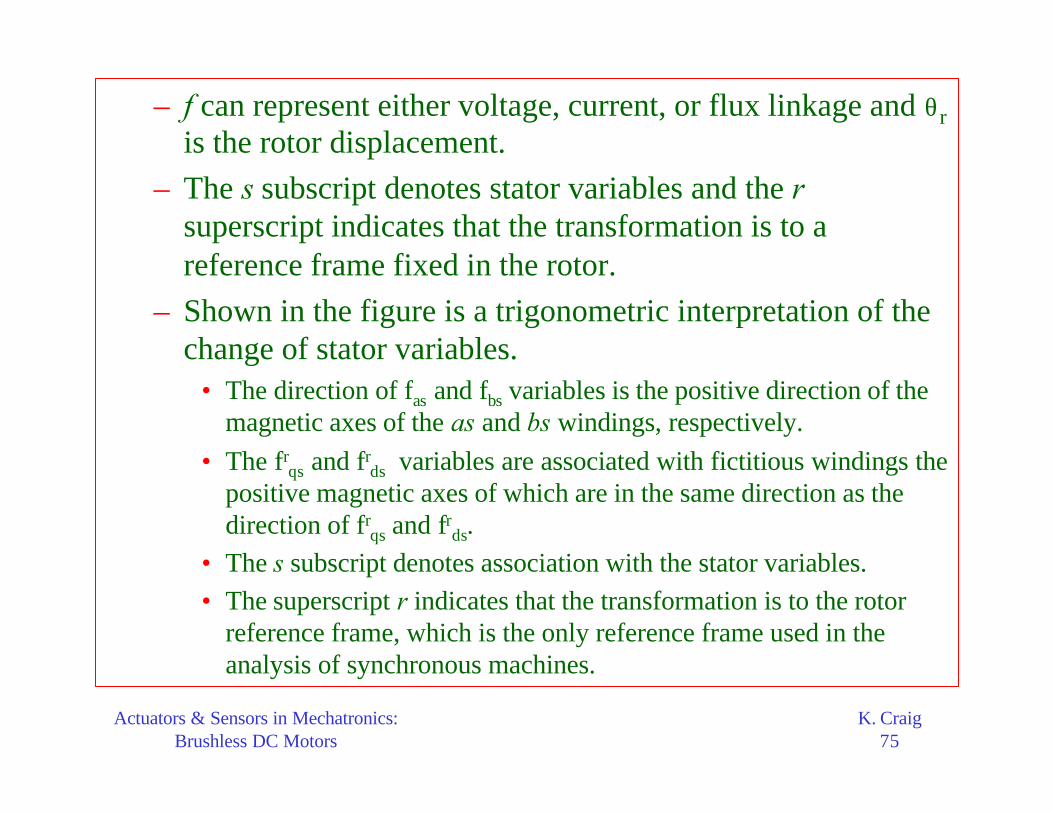
– f can represent either voltage, current, or flux linkage and θris the rotor displacement.
– The s subscript denotes stator variables and the rsuperscript indicates that the transformation is to a reference frame fixed in the rotor.
– Shown in the figure is a trigonometric interpretation of the change of stator variables.
• The direction of fas and fbs variables is the positive direction of the magnetic axes of the as and bs windings, respectively.
• The frqs and fr
ds variables are associated with fictitious windings the positive magnetic axes of which are in the same direction as thedirection of fr
qs and frds.
• The s subscript denotes association with the stator variables.
• The superscript r indicates that the transformation is to the rotor reference frame, which is the only reference frame used in the analysis of synchronous machines.

Actuators & Sensors in Mechatronics:Brushless DC Motors
K. Craig76
Trigonometric Interpretation of the Change of Stator Variables

Actuators & Sensors in Mechatronics:Brushless DC Motors
K. Craig77
– Transformation
asas s as
bsbs s bs
dv r i
dtd
v r idt
λ= +
λ= +
abs s abs absv r i p= + λ
as s as as
bs s bs bs
v r 0 i d
v 0 r i dt
λ = + λ
Matrix Form
asabs
bs
ff
f
=
ss
s
r 0r
0 r
=

Actuators & Sensors in Mechatronics:Brushless DC Motors
K. Craig78
– Transformationas asas as asbs bs asm
bs bsas as bsbs bs bsm
L i L i
L i L i
λ = + + λ
λ = + + λ
as asas asbs as r'm
bs bsas bsbs bs r
L L i sin
L L i cos
λ θ = + λ λ − θ
'abs s abs mL iλ = + λ
asm r' 'm m
bsm r
sin
cos
λ θ λ = = λ λ θ
asas asbs sss
bsas bsbs ss
L L L 0L
L L 0 L
= =

Actuators & Sensors in Mechatronics:Brushless DC Motors
K. Craig79
– Transformation
rasr rqs
rbsr rds
fcos sinf
fsin cosf
θ θ = θ − θ
1r r r rabs s qds s qdsf K f K f
− = =
r rqds s absf K f=
abs s abs absv r i p= + λ1r r
abs s qdsf K f−
=
( ) ( ) ( )1 1 1r r r r r r
s qds s s qds s qdsK v r K i p K− − − = + λ
Multiply by rsK
substitute
( )( ) ( ) ( ) ( ) ( )1 1 1r r r r r r r r r
s s qds s s s qds s s qdsK K v K r K i K p K− − − = + λ
( ) ( )1r r r r r
qds s qds s s qdsv r i K p K− = + λ

Actuators & Sensors in Mechatronics:Brushless DC Motors
K. Craig80
– Transformation
( ) ( )1r r r r r
qds s qds s s qdsv r i K p K− = + λ
( ) ( ) ( )( )1 1r r r r r r r r
qds s qds s s qds s s qds
r r rs qds r dqs qds
v r i K p K K K p
r i p
− − = + λ + λ
= + ω λ + λrdsr
dqs rqs
λλ =
− λ
For a magnetically linear system: 'abs s abs mL iλ = + λ
( ) ( )1 1r r r r '
s qds s s qds mK L K i− −
λ = + λ

Actuators & Sensors in Mechatronics:Brushless DC Motors
K. Craig81
– Transformation
( ) ( )1 1r r r r r r r '
s s qds s s s qds s m
r r r 'qds s qds s m
rs msr 'rqs
qds mrs ms ds
K K K L K i K
L i K
L L 0 0i
0 L L 1i
− −
λ = + λ
λ = + λ
+ λ = + λ +
l
l

Actuators & Sensors in Mechatronics:Brushless DC Motors
K. Craig82
– In our new system of variables, the flux linkage created by the permanent magnet appears constant. Hence, our fictitious circuits are fixed relative to the permanent magnet and, therefore, fixed in the rotor. We have accomplished the goal of eliminating flux linkages which vary with θr.
– In expanded form, the voltage equations are:
– where
r r r rqs s qs r ds qs
r r r rds s ds r qs ds
v r i p
v r i p
= + ω λ + λ
= − ω λ + λ
( )
( )
r r rqs ss qs s ms qs
r r ' r r 'rds ss ds m s ms ds m
L i L L i
L i L L i
λ = = +
λ = + λ = + + λ
l
l

Actuators & Sensors in Mechatronics:Brushless DC Motors
K. Craig83
– Substitution
– The electromagnetic torque is obtained by expressing ias
and ibs in terms of irqs and ir
ds. In particular:
( )
( )
r r r 'rqs s ss qs r ss ds r m
r r rds s ss ds r ss qs
v r pL i L i
v r pL i L i
= + + ω + ω λ
= + − ω
r r 'rs ss r ssqs qs r m
r rr ss s ssds ds
r pL Lv i
L r pLv i 0
+ ω ω λ = + − ω +
' r re m qs
PT i
2= λ
(positive for motor action)

Actuators & Sensors in Mechatronics:Brushless DC Motors
K. Craig84
• Time-Domain Block Diagrams and State Equations– Nonlinear System Equations
– Voltage Equations
– Relationship between torque and rotor speed
r r 'rs ss r ssqs qs r m
r rr ss s ssds ds
r pL Lv i
L r pLv i 0
+ ω ω λ = + − ω +
re m r L
2 d 2T J B T
P dt P
ω = + ω +

Actuators & Sensors in Mechatronics:Brushless DC Motors
K. Craig85
– Rewriting the equations:
( )
( )
( )
r r r 'rqs s s qs s s r ds m r
r r rds s s ds s s r qs
e L m r
v r 1 p i r i
v r 1 p i r i
2T T B Jp
P
= + τ + τ ω + λ ω
= + τ − τ ω
− = + ω
sss
s
L
rτ =
( )
( )
( )
r r r 'rsqs qs s s r ds m r
s
r r rsds ds s s r qs
s
r e Lm
1/ ri v r i
p 1
1/ ri v r i
p 1
P / 2T T
Jp B
= − τ ω − λ ωτ +
= + τ ωτ +
ω = −+
' r re m qs
PT i
2= λ

Actuators & Sensors in Mechatronics:Brushless DC Motors
K. Craig86
Time-Domain Block Diagram of a
Brushless DC Machine

Actuators & Sensors in Mechatronics:Brushless DC Motors
K. Craig87
– State Variables
– The state variables are the stator currents irqs and ir
ds, the rotor speed ωr, and the rotor position θr. Here we will omit θr since it is considered a state variable only when shaft position is a controlled variable. Also it can be established from ωr.
– In Matrix Form the state-variable equations are:
'rs m
r r r rss ss ssqs qs r ds qs
r r r rsds ds r qs ds
ss ssr r L2 'r
m m
r 10 0 0
L L Li i i v
rd 1i 0 0 i i 0 0 v
dt L L0 T
P 1BP 0 00 2 J2 J J
λ − −
− ω
= − + ω + ω ω λ − −

Actuators & Sensors in Mechatronics:Brushless DC Motors
K. Craig88