Embed Size (px)
Citation preview

Order this document by:
A N 1 2 4 9 / D
Fre
esc
ale
Se
mic
on
du
cto
r, I
nc
...
Brushed DC Motor Control Using the MC68HC16Z1by Lawrence Donahue
INTRODUCTIONThe MC68HC16Z1 is a 16-bit high speed microcontroller that incorporates a number of different modules.One of these modules is the General Purpose Timer (GPT), which provides various timing functions includ-ing pulse width modulation (PWM) output. PWM is very useful for motor control. This note describes a DCmotor control system that provides for constant motor speed using PWM.
The control system uses motor shaft rotation period as its input, monitors motor speed, and changes PWMoutput duty cycle to either speed up or slow down the motor in order to maintain constant speed. TheM68HC16 interfaces to the motor via the DEVB103 Logic to Motor Interface Module, which is described indetail in Freescale Application Note AN1300, Interfacing Microcomputers to Fractional Horsepower Motors.
BACKGROUNDA DC motor is a transducer that converts electrical energy to mechanical energy. As shown in Figure 1, anideal motor would run without loss and store no energy.
Figure 1 Ideal Motor
The model of an ideal motor is similar to that of an ideal transformer, but only one side has voltage (V) andcurrent (I) variables, while the other side has velocity (U) and force (F) variables. The voltage-velocity andcurrent-force relationships are:
KIs = FmVs = KUm
However, a real motor is far from ideal, both electrically and mechanically. The electrical side consists es-sentially of wire wound around a core. The windings have an associated inductance, and since wire hasresistivity, there is also a finite resistance. Inertia affects mechanical operation. A rotating motor does notinstantaneously stop when disconnected from its power source, but rather slows down and eventually stops.
Is FmK : 1
Vs Um
AN1249 IDEAL MOTOR
For More Information On This Product,
Go to: www.freescale.com

F
ree
sca
le S
em
ico
nd
uc
tor,
I
nc
...
Similarly, a stopped motor does not instantaneously jump up to speed when power is applied. Because themotor resists step changes in the velocity (the across variable) there is an element that looks capacitive.Because an unpowered motor eventually slows down, it is lossy. A more realistic model of a motor includesan electrical resistance and inductance and a mechanical resistance and compliance, along with an addi-tional load, as shown in Figure 2.
Figure 2 Model Motor with Load
Figure 3 shows the electrical equivalent circuit, looking into the terminals of the ideal transducer.
Figure 3 Electrical Equivalent of Mechanics
Figure 4 is the second-order electronic equivalent of the motor.
Figure 4 Electrical Equivalent of a Motor
Is FmK : 1
Vs Um
AN1249 NONIDEAL MOTOR
LeRe
Rm RLCm
AN1249 MECH ELEC EQIV
Ceq
Cm
K2---------= Req K2RmRL Rm RL+( ) 1–
=
Vs
AN1249 MOTOR ELEC EQUIV
LeRe
ReqCeq
Freescale Semiconductor, Inc.
AN1249/D 2
For More Information On This Product, Go to: www.freescale.com

F
ree
sca
le S
em
ico
nd
uc
tor,
I
nc
...
The result is a second order model system with a natural frequency of:
ω0 = [LeCeq]-1/2
The input to this model system is a pulse-width modulated signal that switches between ground and a con-stant voltage. Switching occurs at a constant frequency with a given duty cycle. If the switching frequencyis sufficiently above the bandwidth of the motor, the motor filters out everything but the DC component ofthe PWM signal, thus averaging it. For example, consider a PWM that switches between 0 volts and V0 voltswith a duty cycle of 25%. The motor behaves as if it were connected to a DC supply of 0.25V0 volts — theduty cycle of the PWM determines the speed of the motor.
In real DC motors, however, the relationship between source voltage and shaft velocity is not linear, andthese relationships vary from motor to motor. Therefore, one desirable characteristic of a motor control sys-tem is the ability to control speed independent of motor characteristics. Also, in many real-world applica-tions, motor loads vary. Hence, another desirable characteristic is the ability to provide constant motorspeed under changing loads. These requirements are addressed by monitoring and controlling motor speedrather than providing a specific voltage or duty cycle.
SYSTEM OVERVIEWThe system has four basic elements, as shown in Figure 5.
Figure 5 System Block Diagram
The first block represents the (MC68HC16Z1EVB) evaluation board that provides system computing andcontrol functions. The MCU is accessed by EVB16 software running on an IBM PC compatible connectedto the EVB via a parallel port. The GPT in the MCU generates a PWM signal which is connected to theDEVB103 logic to motor interface module (Figure 6). The logic to motor interface module takes logic levelPWM signals and switches the power transistors of an H-bridge to provide motor drive power up to 60 Vand 3 A. The motor is the third element of the system. The fourth element consists of an opto-sensor and asensor board that conditions sensor output so that the period of motor shaft rotation can be measured bysoftware, to complete the feedback loop. Figure 7 shows a typical comparator with unipolar output. Com-parator component values depend on sensor output level.
Figure 10 shows the open loop system function. The input is D, the duty cycle that determines the speedof the motor. The output is ωA, the actual speed of the motor. Hence, the transfer function of the motor is:
ωA / D = [s2 + 2αs + ω02]-1
Observations of the actual motor indicate that the open loop system function is overdamped, and thus lookssomewhat like a first order system.
AN1249 SYS BLOCK
68HC16Z1EVB LOGIC-TO-MOTORINTERFACE
SENSOR BOARD
MOTOR
OPTICALSENSOR
Freescale Semiconductor, Inc.
AN1249/D 3
For More Information On This Product, Go to: www.freescale.com

F
ree
sca
le S
em
ico
nd
uc
tor,
I
nc
...
Figure 6 Logic To Motor Interface Schematic
Figure 7 Sensor Output Conditioning Circuit
A BOT
D1
MBR030CURRENT SENSE (CS+)
CURRENT SENSE GND (CS-)
GROUND GROUND
B+ (12-60V)
+M
-M
C1390 mF
++5V
C51 mF
141
2
4
5
9
10
12
13
R12
R2210K
R23
R2410K
R2510K
R13
R14
R15
1K
1K
1K
1K
10K
D512V
D74.7V
R93.9K
R212K
R10220
R75.6K
Q3MPSA06
Q4MPSA06
R8100
R6220
Q2MPSA56
C61 mF
R205.6K
Q6MPSA06
R18100
R19220
Q7MPSA56
R17220
C71 mF
R265.1K1W
R35.1K1W
D612V
D84.7V
D94.7V
D104.7V
7
11
8
6
3
+5V
+5V
MC74HC00
U1A
U1B
U1C
U1DD414V
Q1
MPSW06
Q6MPSW06
U3MC78L05ACP
VI VOGNDC2
1 mFC41 mF
R162K
R27120R5 1K
R11 220
R1 470
R2 220
R4 470
+5V
D3PWR
D2
MBR030
D12MBR030
D11MBR030
C31 mF
U2MC34151
B TOP
A TOP
B BOT
A BOT
10
3
12
1121
9
4
B TOP
B BOT
A TOP
MC74HC00
MC74HC00
MC74HC00
1234
NCA INGNDB IN
NCA OUT
VCCB OUT
8765
6587
MPM3002
Q5MPSA06
LTM SCHEM
R1
Q1
+V
V OUT
+
–
–V
R2
R3
RB
R4
D1
Z1
VIN
V REF
SCHMITT COND CKT
Freescale Semiconductor, Inc.
AN1249/D 4
For More Information On This Product, Go to: www.freescale.com

Fre
esc
ale
Se
mic
on
du
cto
r, I
nc
...
Figure 8 System Functional Diagram
The system is to maintain the motor speed ωA constant at the desired speed ωD. Examining the closed-loop system function diagram shown in Figure 9 yields:
D = D + [ωD - ωA]/ωDor
ωA =ωD
Figure 9 Closed Loop System
Therefore the input-output relationship is independent of the motor given a constant input ωD. However,when the transfer function of the motor changes (i.e., when the load on the motor changes) or when thedesired speed changes, the system must adjust the value of D to make the actual motor speed equal thedesired speed. Further examination of the system function yields:
D = D + [ωD - ωA] / ωD = (ωA/Vref) (s2 + 2as + ω02)
which simplifies to:
ωA = Vref (1 + D) [s2 + 2αs +ω02 +Vref/ωD]-1
As shown in Figure 10, the poles of the closed loop system function differ from those of the open loop func-tion. The poles become:
s1 = - α + [α2 - ω02 - Vref/ωD]1/2
s2 = - α – [α2 - ω02 - Vref/ωD]1/2
Figure 10 Open Loop and Closed Loop Poles in Complex Plane
AN1249 SYS FUNC BLOCK
s2 αs ωo2+ +( )
1–VREF ωAD
s2 2αs ωo2+ +( )
1–VREF ωADΣωD ΣωD
1–
AN1249 LOOP POLAR
– αx x
Re
Im
– α
x
x
Re
Im
OPEN LOOP CLOSED LOOP
Freescale Semiconductor, Inc.
AN1249/D 5
For More Information On This Product, Go to: www.freescale.com

F
ree
sca
le S
em
ico
nd
uc
tor,
I
nc
...
The poles are thus functions of Vref/ωD. If Vref/ωD gets large enough, the poles become complex, and theactual motor speed, ωA, rings as it settles to its final value of ωD. The envelope and overshoot of the ringingare both dependent on several factors, including the control algorithm, the voltage and duty cycle used forthe PWM, the desired speed, the load on the motor, and the motor itself.
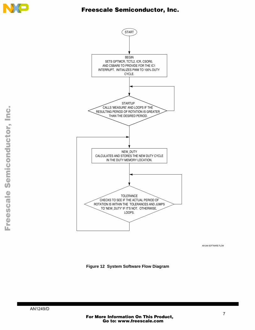
SOFTWARE CONTROLThe software that controls the motor brings the motor up to speed as fast as possible, given the voltageconstraints of the system, and then maintains that desired speed. Figure 12 is an overall block diagram ofthe system software. Figure 13 through Figure 15 provide flow diagrams of the three major blocks of code.
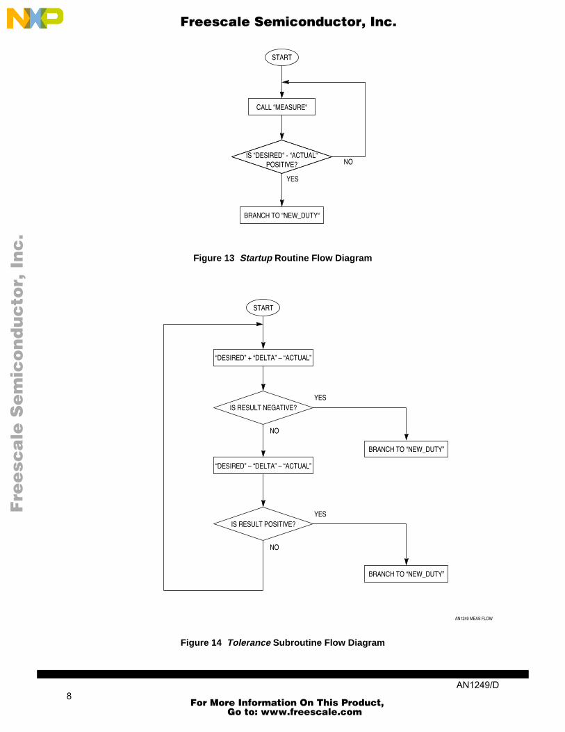
Begin sets up the registers that control the GPT, sets the desired period of rotation and tolerances, and setsthe PWM to 100%. Startup then monitors the period of rotation of the motor by using the subroutine mea-sure (refer to Figure 13). If measure returns a period longer than that desired, the program loops back tostartup. When measure returns a period shorter than that desired, the program continues with new_duty(refer to Figure 13), which calculates and sets the new duty cycle with the algorithm:
Dnew = Dold [1 + (TD - TA)/TA]-1
where TD and TA are the desired and actual periods of rotation, respectively. Following new_duty, tolerance(refer to Figure 14) checks to see if the measured period is within the tolerances designated in begin.
For experimental purposes, a second control algorithm that modifies the duty cycle in a different mannerwas also implemented. The routine compares TD and TA and determines whether TA is greater or less thanTD, then takes one of the following actions:
• If the two periods are within 8 GPT counts, the duty cycle is not modified.• If TD - 8 is greater than TA, the duty cycle is decreased.• if TD + 8 is less than TA, the duty cycle is increased.
The routine then looks at the magnitude of the difference between the two periods to determine by howmuch the duty cycle is to be modified. Figure 16 is a flow diagram of the alternate control algorithm.
Figure 11 is a plot of the increment by which the duty cycle is modified as a function of the difference be-tween TD and TA.
Figure 11 Modify Value vs. Difference
AN1249 MOD VS DIFF
GPT COUNTS
MODIFYVALUE
TD TA–
8
6
4
2
#$8 #$10 #$40 #$100
Freescale Semiconductor, Inc.
AN1249/D 6
For More Information On This Product, Go to: www.freescale.com
F
ree
sca
le S
em
ico
nd
uc
tor,
I
nc
...
Figure 12 System Software Flow Diagram
START
BEGINSETS GPTMCR, TCTL2, ICR, CSOR0,
AND CSBAR0 TO PROVIDE FOR THE IC1 INTERRUPT. INITIALIZES PWM TO 100% DUTY
CYCLE.
STARTUPCALLS 'MEASURE' AND LOOPS IF THE
RESULTING PERIOD OF ROTATION IS GREATER THAN THE DESIRED PERIOD.
NEW_DUTYCALCULATES AND STORES THE NEW DUTY CYCLE
IN THE DUTY MEMORY LOCATION.
TOLERANCECHECKS TO SEE IF THE ACTUAL PERIOD OF
ROTATION IS WITHIN THE TOLERANCES AND JUMPS TO 'NEW_DUTY' IF IT'S NOT. OTHERWISE,
LOOPS.
AN1249 SOFTWARE FLOW
Freescale Semiconductor, Inc.
AN1249/D 7
For More Information On This Product, Go to: www.freescale.com
F
ree
sca
le S
em
ico
nd
uc
tor,
I
nc
...
Figure 13 Startup Routine Flow Diagram
Figure 14 Tolerance Subroutine Flow Diagram
START
CALL “MEASURE“
IS “DESIRED“ - “ACTUAL“POSITIVE?
YES
BRANCH TO “NEW_DUTY“
NO
START
“DESIRED” + “DELTA” – “ACTUAL”
YESIS RESULT NEGATIVE?
BRANCH TO “NEW_DUTY”
NO
“DESIRED” – “DELTA” – “ACTUAL”
IS RESULT POSITIVE?
BRANCH TO “NEW_DUTY”
NO
YES
AN1249 MEAS FLOW
Freescale Semiconductor, Inc.
AN1249/D 8
For More Information On This Product, Go to: www.freescale.com

F
ree
sca
le S
em
ico
nd
uc
tor,
I
nc
...
Figure 15 New_duty Routine Flow Diagram
START
DESIRED – ACTUAL
GREATER THAN NO
NEGATE RESULT
DIVIDE BY ACTUAL
SHIFT ONE SPACE TO THE RIGHT
SUBTRACT RESULT FROM 1 ($8000)
DIVIDE BY ACTUAL
SHIFT ONE SPACE TO THE RIGHT
ADD RESULT TO1 ($8000)
MULTIPLY RESULTBY DUTY
SHIFT ONE SPACETO THE RIGHT
JUMP TO"TOLERANCE"
.
LOAD RESULT INDUTY
YES
AN1249 DUTY FLOW
ZERO?
Freescale Semiconductor, Inc.
AN1249/D 9
For More Information On This Product, Go to: www.freescale.com

F
ree
sca
le S
em
ico
nd
uc
tor,
I
nc
...
Figure 16 Alternate Control Algorithm Flow Diagram
AN1249 ALT FLOW
START
SET TMSK1 TO 0100TO MASK FOR IC1 INTERRUPT
SET A TO 0
IS A < 2?YES “PERIOD” ON IC1 INTERRUPT
INCREMENT A.
A = 2? TIC1 => E
RTI
NO
TIC1 => D
ACTUAL = –(E – D)
SET A TO 2.
TFLG1 = F880
RTI
TFLG = F880
TMSK1 = 0000TO DISABLE IC1
INTERRUPT
RTS
NO
YES
Freescale Semiconductor, Inc.
AN1249/D 10
For More Information On This Product, Go to: www.freescale.com

F
ree
sca
le S
em
ico
nd
uc
tor,
I
nc
...
OPERATIONBoth control routines were evaluated on two different motors. One motor was a slower, less responsive mo-tor that worked well with the second increment/decrement approach and not so well with the first approach.The second motor was faster and more responsive and worked very well with the first approach but not sowell with the second approach.
CODE LISTINGSListings 1 and 2 contain code for the first implementation of the control routine and the second increment/decrement implementation of the control routine, respectively.
Listing 1 First Control Implementation.
INCLUDE 'EQUATES.ASM' ;table of EQUates for common register addr INCLUDE 'ORG00000.ASM' ;initialize reset vector
ORG $80 DC.W PERIOD ;IC1 jumps to PERIOD
ORG $0400 ;offsets from IX for variablesDESIRED EQU $0 ;location for storing the desired periodDELTA EQU $2 ;location for storing the period toleranceACTUAL EQU $4 ;location for storing the measured periodDUTY EQU $6 ;location for storing the present duty cycleTEMP1 EQU $8 ;location for storing any temporary valuesTEMP2 EQU $A ; " " " " " "TEMP3 EQU $C ; " " " " " "TEMP4 EQU $E ; " " " " " "
ORG $0200 ;start program after interrupt vectors***** Initialization Routines ***** INCLUDE 'INITRAM.ASM' ;initialize and turn on SRAM ;set stack (SK=1, SP=03FE) INCLUDE 'INITSYS.ASM' ;initially set EK=F, XK=0, YK=0, ZK=0 ;set sys clock at 16.78 MHz, disable COP
***** Here we go with motor control. *****
BEGIN LDD #$0083 ;Put the GPT into supervisor mode (the default STD GPTMCR ;mode) and sets interrrupt priority level to 3. LDD #$FFF9 STD CSBAR0 LDD #$7801 ;assert AVEC and other int. vector stuff STD CSOR0 LDD #$1740 ;Set IC1 to be highest GPT priority, GPT to... STD ICR ;highest priority interrupt, and vector base... ;address to 4. LDY #$400 ;Beginning for variables in indirect addresses. LDD #$A00 ;Set the desired period to $A00 GPT counts. STD DESIRED,Y LDD #$80 ;Set the tolerence to +/- $80 GPT counts. STD DELTA,Y LDAA #$01 ;Set IC1 to capture only on a positive edge. STAA TCTL2 LDD #$0062 ;Set the input of PWMCNT to the system clock... STD PWMC ;divided by 128 and set PWMA to be allways high.STARTUP BSR MEASURE ;Branch to measure period of revolution CPE DESIRED,Y ;Compare the measured period with the desired BPL STARTUP ;and loop if motor is slower than desired. LDD #$00FF ;Store the value $FF in... STD DUTY,Y ;...the user defined duty cycle location and... STAB PWMA ;...in the GPT PWMA register thus setting the... ;...duty cycle of PWMA to $FF/$100. LDD #$0060 ;Change PWMA's otput to be from a constant... STD PWMC ;...output to a PWM output with duty cycle... ;...in the PWMA register. JMP NEW_DUTY ;branch to get new duty cycleMEASURE LDD #$0104 ;Enable the IC1 interrupt and the TCNT clock... STD TMSK1 ;...to be the OC1 pin. LDAA #$00 ;The A register is used to keep track of how...MEAS_LOOP CMPA #$02 ;...many input captures have taken place--with... ;...two, we can measure the period. BMI MEAS_LOOP ;Loop if two measurements have not been made. LDD #$0000 ;If two interrupts have taken place,reset for... STD TMSK1 ;...no interrupts (disable IC1). RTS ;Return from "measure" subroutine.TOLERANCE BSR MEASURE ;Branch to "measure" subroutine.
Freescale Semiconductor, Inc.
AN1249/D 11
For More Information On This Product, Go to: www.freescale.com

F
ree
sca
le S
em
ico
nd
uc
tor,
I
nc
...
LDE ACTUAL,Y ;Load the measured period in E LDD DESIRED,Y ;Load the desired period in D. ASLD ;Double the desired period and put in D. SDE ;Subtract twice the desired period from the... ;...actual period, and if the actual period is... BPL TOO_SLOW ;...more than twice the desired, branch to the... ;...the "too_slow" code. LDD DESIRED,Y ;Load the desired period in D. LDE ACTUAL,Y ;Load the measured period in E. ASLE ;Half the desired period and put in D. SDE ;Subtract half the desired period from the... ;...actual period, and if the actual period is... BMI TOO_FAST ;...less than half the desired, branch to the... ;...the "too_fast" code. BRA WITHIN ;Otherwise branch to the "within" code.TOO_SLOW LDD #$00FF STD DUTY,Y ;Set the user defined duty cycle location to $FF. STAB PWMA ;Set the PWMA register for a $FF/$100 duty cycle. BRA WAIT ;Branch to the "wait" code.TOO_FAST LDD #$0000 STD DUTY,Y ;Set the user defined duty cycle location to 0. STAB PWMA ;Set the PWMA register for a 0% duty cycle. BRA WAIT ;Branch to the "wait" code.WITHIN LDD DESIRED,Y ;Load the desired period in D. LDE DELTA,Y ;Load the period tolerance in E. ADE ;Add the two together to get the maximum... ;...period allowed and store in E. LDD ACTUAL,Y ;Load the measured period in D and... SDE ;...subtract it from the max period allowed. BMI JUMP ;Branch to get new duty cycle if slow. LDD DESIRED,Y ;Load the desired period in D. LDE DELTA,Y ;Load the period tolerance in E. NEGE ;Negate the period tolerance. ADE ;Add the two together to get the minimum... ;... period allowed and store in E. LDD ACTUAL,Y ;Load the measured period in D and... SDE ;...subtract it from the min period allowed. BPL JUMP ;Branch to get new duty cycle if fast.JUMP JMP NEW_DUTY ;Jump to "new_duty" code.WAIT LDE #$2 ;Load the number of loops to wait for in E. LDD #$0000 ;Initialize temporary loacation #1 with zero... STD TEMP1,Y ;...because it will be used to count the number... ;...of loops.WAIT_LOOP INCW TEMP1,Y ;Increment the counter loop. CPE TEMP1,Y ;Has the count (TEMP1,Y) reached the value in E? BNE WAIT_LOOP ;Loop if the count hasn't reached the value in E. BRA TOLERANCE ;Branch back to tolerance once the count has... ;...reached the specified value.PERIOD INCA ;This code is executed when the IC1 interrupt... ;...takes place. The code first increments A... ;...which is used to count how many edges have... ;...been detected in the present "measure" routine. CMPA #$02 ;Compare the number of edge detections to 2. BEQ DELTA_T ;If second edge, jump to DELTA_T routine. LDE TIC1 ;Load the TCNT input capture value in E. BCLR TFLG1,#$01 ;Clear the IC1 interrupt flag. RTI ;Return from the IC1 interrupt.DELTA_T LDD TIC1 ;Load the TCNT input capture value in D. SDE ;Subtract the second time (D) from first (E)... NEGE ;...and change the sign to get possitive value... ;...for the period. STE ACTUAL,Y ;Store the period in the appropriate location... ;...of user specified memory (ACTUAL,Y). LDAA #$02 ;Set A to 2 to break out of MEAS_LOOP above. BCLR TFLG1,#$01 ;Clear the IC1 interrupt flag. RTI ;Return from the IC1 interrupt.NEW_DUTY LDD ACTUAL,Y ;Load the measured period into D. LDE DESIRED,Y ;Load the desired period into E. SDE ;Subtract the desired period from the measured... ;...and put result in E. BPL PLUS ;Branch to the "plus" code if the desired period... ;...is greater than the measured period.MINUS NEGE ;-(Desired-Measured) ==> E TED ;-(Desired-Measured) ==> E LDX ACTUAL,Y ;Load the measured period into the IX register. FDIV ;(Actual-Desired)/Actual ==> IX STX TEMP1,Y ;Store the result in user defined memory... LDD TEMP1,Y ;...TEMP1,Y and store the result in D. LSRD ;Shift bits one place to the right because in... LDE #$8000 ;...this section, the convention changes and... ;...$8000 becomes equal to 1 instead of 0.5. SDE ;Subtract the word shifted above from $8000 thus... ;...performing: 1-(Actual-Desired)/Actual ==> E. BRA FACTOR ;Branch to section of code that will scale the... ;...present duty cycle by the result stored in E.
Freescale Semiconductor, Inc.
AN1249/D 12
For More Information On This Product, Go to: www.freescale.com

F
ree
sca
le S
em
ico
nd
uc
tor,
I
nc
...
PLUS LDX ACTUAL,Y ;Load the measured period into the IX register. TED ;(Desired-Actual) ==> E FDIV ;(Desired-Actual)/Actual ==> IX STX TEMP1,Y ;Store the result in user defined memory... LDD TEMP1,Y ;...TEMP1,Y then load the result in D. LSRD ;Shift bits one place to the right because in... LDE #$8000 ;...this section, the convention changes and... ;...$8000 becomes equal to 1 instead of 0.5. ADE ;Add the word shifted above to $8000 thus... ;...performing: 1+(Desired-Actual)/Actual ==> E.FACTOR STE TEMP1,Y ;Store the result from "minus" or "plus" in... LDX TEMP1,Y ;...user defined memory TEMP1,Y then load the... ;...result in IX. LDD DUTY,Y ;Load D with the present duty cycle. FDIV ;Divide the presest duty cycle by the factor... ;...calculated in "minus" or "plus" above... ;...thus performing the operation:... ;...DUTY/(1+(Desired-Actual)/Actual) ==> IX. STX TEMP1,Y ;Store this result in user defined memory... LDD TEMP1,Y ;...and then loading the result in D. LSRD ;Shift the result one place to the right to.. ;...compensate for the shift from above. STD DUTY,Y ;Load this result in the memory location... ;...designated to be the duty cycle--DUTY,Y. LDE #$00FF ;Load E with $FF and compare with the result... SDE ;...as a sanity check to make sure that the.. ;...resulting duty cycle makes sense. BPL OK ;If the result passes the sanity check, branch... ;...to OK code,... LDD #$00FF ;...otherwise, load the maximum allowable duty... STD DUTY,Y ;...cycle ($FF/$100) into DUTY,Y.OK STAB PWMA ;Store the new duty cycle in the GPT PWMA register. JMP TOLERANCE ;Loop back to TOLERANCE.
Listing 2 Second (Increment/Decrement) Control Implementation
INCLUDE 'EQUATES.ASM' ;table of EQUates for common register addr INCLUDE 'ORG00000.ASM' ;initialize reset vector
ORG $80 DC.W PERIOD ;IC1 jumps to PERIOD
ORG $0400 ;Offsets from IX for variablesDESIRED EQU $0 ;Location for storing the desired period.DELTA EQU $2 ;Location for storing the period tolerance.ACTUAL EQU $4 ;Location for storing the measured period.DUTY EQU $6 ;Location for storing the present duty cycle.TEMP1 EQU $8 ;Location for storing any temporary values.TEMP2 EQU $A ;Location for storing any temporary values.TEMP3 EQU $C ;Location for storing any temporary values.TEMP4 EQU $E ;Location for storing any temporary values.
ORG $0200 ;start program after interrupt vectors***** Initialization Routines ***** INCLUDE 'INITRAM.ASM' ;initialize and turn on SRAM ;set stack (SK=1, SP=03FE) INCLUDE 'INITSYS.ASM' ;initially set EK=F, XK=0, YK=0, ZK=0 ;set sys clock at 16.78 MHz, disable COP
***** Here we go with motor control. *****
BEGIN LDD #$0083 ;Put the GPT into supervisor mode (the default... STD GPTMCR ;...mode) and sets interrupt priority level to 3. LDD #$FFF9 STD CSBAR0 LDD #$7801 ;assert AVEC and other int. vector stuff STD CSOR0 LDD #$1740 ;Set IC1 to be highest GPT priority, GPT to... STD ICR ;...highest priority interrupt, and vector base... ;...base address to 4. LDY #$400 ;Beginning for variable in indirect addresses. LDD #$A00 ;Set the desired period to $A00 GPT counts. STD DESIRED,Y LDD #$8 ;Set the period tolerance to +/- $8 GPT counts. STD DELTA,Y LDAA #$01 ;Set IC1 to capture only on a positive edge. STAA TCTL2 LDD #$0062 ;Set the input of PWMCNT to the system clock... STD PWMC ;...divided by 128 and set PWMA to be high always.STARTUP BSR MEASURE ;Branch to measure period of revolution. CPE DESIRED,Y ;Cpmpare the measured period with the desired... BPL STARTUP ;...and loop if motor is slower than desired LDD #$00FF ;Store the value $FF in...
Freescale Semiconductor, Inc.
AN1249/D 13
For More Information On This Product, Go to: www.freescale.com

F
ree
sca
le S
em
ico
nd
uc
tor,
I
nc
...
STD DUTY,Y ;...the user defined duty cycle location and... STAB PWMA ;...in the GPT PWMA register thus setting the... ;...duty cycle of PWMA to $FF/$100. LDD #$0060 ;Change PWMA's output to be from a constant... STD PWMC ;...ooutput to a PWM output with duty cycle... ;...in the PWMA register. JMP NEW_DUTY ;Branch to get new duty cycle.MEASURE LDD #$0104 ;Enable the IC1 interrupt and the TCNT clock... STD TMSK1 ;...to be the OC1 pin (as a reference for debug). LDAA #$00 ;The A register os used to keep track of how...MEAS_LOOP CMPA #$02 ;...many input captures have taken place--with... ;...two, we can measure the period. BMI MEAS_LOOP ;Loop if two measurements have not been made. LDD #$0000 ;If two interrupts have taken place, reset for... STD TMSK1 ;...no interrupts (disable IC1). RTS ;Return from "measure" subroutine.TOLERANCE BSR MEASURE ;Branch to "measure" subroutine. LDD DESIRED,Y ;Load the desired period into D. LDE DELTA,Y ;Load the period tolerance into E. ADE ;Add the two together to get the maximum... ;...period allowed and store the value in E. LDD ACTUAL,Y ;Load the measured period in D and... SDE ;...subtract it from the max period allowed. BMI JUMP ;Branch to get new duty cycle if slow. LDD DESIRED,Y ;Load the desired period into D. LDE DELTA,Y ;Load the period tolerance into E. NEGE ;Negate the period tolerance. ADE ;Add the two together to get the minimum... ;...period allowed and store it in E. LDD ACTUAL,Y ;;Load the measured period in D and... SDE ;...subtract it from the min period allowed. BPL JUMP ;Branch to get new duty cycle if fast.JUMP JMP NEW_DUTY ;Jump to "new_duty" code which calculates the... ;...new duty cycle.WAIT LDE #$2 ;Load the number of loops to wait for in E. LDD #$0000 ;Initialize temporary location #1 with zero... STD TEMP1,Y ;...because it will be used to keep track of... ;...the number of loops.WAIT_LOOP INCW TEMP1,Y ;Increment the loop counter. CPE TEMP1,Y ;Has the count (TEMP1,Y) reached the value in E? BNE WAIT_LOOP ;Loop if the count hasn't reached the value in E? BRA TOLERANCE ;Branch back to tolerance once the count has... ;...reached the specified value.PERIOD INCA ;This count is executed when the IC1 interrupt... ;takes place. The code first increments A which... ;...is used to count how many edges have been... ;...detected in the present "measure" routine. CMPA #$02 ;Compare the number of edge detections to 2. BEQ DELTA_T ;If second edge, jump to DELTA_T routine. LDE TIC1 ;Load the TCNT input capture value in E. BCLR TFLG1,#$01 ;Clear the IC1 interrupt flag RTI ;Return from the IC1 interrupt.DELTA_T LDD TIC1 ;Load the TCNT input capyure value in D. SDE ;Subtract the second time (D) from first (E)... NEGE ;...and change the sign to get positive value... ;...for the period. STE ACTUAL,Y ;Store the measured period in the appropriate... ;location of user specified memory (ACTUAL,Y). LDAA #$02 ;Set A to 2 to break out of MEAS_LOOP above. BCLR TFLG1,#$01 ;Clear the IC1 interrupt flag. RTI ;Return from the IC1 interrupt.NEW_DUTY LDD ACTUAL,Y ;Load the measured period into D. LDE DESIRED,Y ;Load the desired period into E. SDE ;Subtract the desired period from the measured... ;...and put the result in E. BPL PLUS ;Branch to the "plus" code if the desired... ;...period is greater than the measured period. NEGE ;Load -(Desired-Measured) into register E.MINUS STE TEMP1,Y ;Store -(Desired-Measured) into location TEMP1,Y. LDD #$0010 ;Load the value $10 into register D. SDE ;Subtract $10 from the discrepency between the... ;...measured period and the desired period. BPL TWO_PL ;If the discrepency is greater than $10, branch... ;...to the "two_pl" code. LDD #$0001 ;If the discrepency is less than $10, load 1... ;...into D to be the value to add to the present... ;...duty cycle. JMP OK_PL ;Jump to the "ok_pl" code.TWO_PL LDE TEMP1,Y ;Load -(Desired-Measured) from TEMP1,Y into E. LDD #$0040 ;Load the value $40 into register D. SDE ;Subtract $40 from the discrepency between the... ;...measured period and the desired period. BPL FOUR_PL ;If the discrepency is greater than $40, branch... ;...to the "four_pl" code. LDD #$0002 ;If the discrepency is less than $40, load 2...
Freescale Semiconductor, Inc.
AN1249/D 14
For More Information On This Product, Go to: www.freescale.com

F
ree
sca
le S
em
ico
nd
uc
tor,
I
nc
...
;...into D to be the value to add to the present... ;...duty cycle. JMP OK_PL ;Jump to the "ok_pl" code.FOUR_PL LDE TEMP1,Y ;Load -(Desired-Measured) from TEMP1,Y into E. LDD #$0100 ;Load the value $100 into register D. SDE ;Subtract $100 from the discrepency between the... ;...measured period and the desired period. BPL EIGHT_PL ;If the discrepency is greater than $100,... ;...branch to the "eight_pl" code. LDD #$0004 ;If the discrepency is less than $100, load 4... ;...into D to be the value to add to the present... ;...duty cycle. JMP OK_PL ;Jump to the "ok_pl" code.EIGHT_PL LDD #$0008 ;Load 8 into D to be the value to add to the... ;...present duty cycle.OK_PL LDE DUTY,Y ;Load the present duty cycle into register E... ADE ;...and add it to the value obtained above... ;...to get the new duty cycle and put result in E. STE DUTY,Y ;Store the new duty cycle in DUTY,Y. LDD DUTY,Y ;Load the new duty cycle from DUTY,Y into D. LDE #$00FF ;Load E with $FF and compare with the result... SDE ;...as a sanity check to make sure that the... ;...resulting duty cycle makes sense. BPL OK ;If the result passes the sanity check, branch... ;...to "ok" code... LDD #$00FF ;...otherwise, load the maximum allowable duty... STD DUTY,Y ;...cycle ($FF/$100) into DUTY,Y. BRA OK ;Branch to "ok" code.PLUS STE TEMP1,Y ;Store (Desired-Measured) into location TEMP1,Y. LDD #$0010 ;Load the value $10 into register D. SDE ;Subtract $10 from the discrepency between the... ;...measured period and the desired period. BPL TWO_MI ;If the discrepency is greater than $10,... ;...branch to the "two_mi" code. LDD #$0001 ;If the discrepency is less than $10, load 4... ;...into D to be the value to add to the... ;...present duty cycle. JMP OK_MI ;Jump to the "ok_mi" code.TWO_MI LDE TEMP1,Y ;Load (Desired-Measured) from TEMP1,Y into E. LDD #$0040 ;Load the value $40 into register D. SDE ;Subtract $40 from the discrepency between the... ;...measured period and the desired period. BPL FOUR_MI ;If the discrepency is greater than $40,... ;...branch to the "four_mi" code. LDD #$0002 ;If the discrepency is less than $40, load 2... ;...into D to be the value to add to the... ;...present duty cycle. JMP OK_MI ;Jump to the "ok_mi" code.FOUR_MI LDE TEMP1,Y ;Load (Desired-Measured) from TEMP1,Y into E. LDD #$0100 ;Load the value $100 into register D. SDE ;Subtract $100 from the discrepency between the... ;...measured period and the desired period. BPL EIGHT_MI ;If the discrepency is greater than $100,... ;...branch to the "eight_mi" code. LDD #$0004 ;If the discrepency is less than $100, load 4... ;...into D to be the value to add to the... ;...present duty cycle. JMP OK_MI ;Jump to the "ok_mi" code.EIGHT_MI LDD #$0008 ;Load 8 into D to be the value to add to the... ;...present duty cycle.OK_MI LDE DUTY,Y ;Load the present duty cycle into register E... SDE ;...and subtract from it the value obtained above... ;...to get the new duty cycle and put result in E. STE DUTY,Y ;Store the new duty cycle in DUTY,Y. LDD DUTY,Y ;Load the new duty cycle from DUTY,Y into D. LDE 0 ;Load E with 0 and compare with the result... SDE ;...as a sanity check to make sure that the... ;...resulting duty cycle makes sense. BMI OK ;If the result passes the sanity check, branch... ;...to "ok" code... LDD #$0 ;...otherwise, load the minimum allowable duty... STD DUTY,Y ;...cycle (0) into DUTY,Y.OK STAB PWMA ;Store the new duty cycle in the GPT PWMA register. JMP TOLERANCE ;Loop back to "tolerance" code.
Freescale Semiconductor, Inc.
AN1249/D 15
For More Information On This Product, Go to: www.freescale.com

F
ree
sca
le S
em
ico
nd
uc
tor,
I
nc
...
ADDITIONAL INFORMATIONThe following Freescale publications contain additional information that may be of use to the reader.
The motor control system described in this note is based on an M68HC11-based system discussed inApplication Note AN1311,Software for an 8-bit Microcontroller Based Brushed DC Motor Drive. Howev-er, the M68HC11system uses a PWM signal as its input.
The DEVB103 Logic to Motor Interface Module is completely described in Application Note AN1300,Interfacing Microcomputers to Fractional Horsepower Motors.
TheMC68HC16Z1 User’s Manual (MC68HC16Z1UM/AD) contains comprehensive information con-cerning the MC68HC16Z1 microcontroller.
TheGPT Reference Manual (GPTRM/AD) contains detailed information concerning the General-Pur-pose Timer (GPT) module in the MC68HC16Z1.
These publications are available through Freescale sales offices and Literature Distribution Centers.
Freescale Semiconductor, Inc.
For More Information On This Product, Go to: www.freescale.com