Embed Size (px)
Citation preview

257See page 152 for trademark acknowledgments.
Engineering
Application Considerations ............................................................................................. 258
Selection/Life CalculationsBall Bearings .......................................................................................................... 262Tapered Roller Bearings ......................................................................................... 264Spherical Roller Bearings ........................................................................................265
Load Capacity/Life TablesBall Bearings – 100 Series ..................................................................................... 266Ball Bearings – 200 & 300 Series ........................................................................... 267Tapered Roller Bearings – 900 & 950 Series ..........................................................268Tapered Roller Bearings – 920 & 970 Series ..........................................................269Spherical Roller Bearings – 1000 & 1100 Series .....................................................270Spherical Roller Bearings – 22200 & 22500............................................................271
General Engineering .........................................................................................................272
Sample Calculations .........................................................................................................274
Installation InstructionsSet Screw Lock........................................................................................................276BOA Concentric .......................................................................................................277Eccentric Lock .........................................................................................................278Insert Replacement Ball Bearings ...........................................................................282950/970 Tapered Roller Bearings ............................................................................283
LubricationBall Bearings ...........................................................................................................284Tapered Roller Bearings ..........................................................................................285Spherical Roller Bearings ........................................................................................286Fittings .....................................................................................................................287
Vibration AnalysisBall Bearings ...........................................................................................................289Tapered Roller Bearings – 900 & 950 Series ..........................................................291Tapered Roller Bearings – 920 & 970 Series ..........................................................292Spherical Roller Bearings – 1000 &1100 Series......................................................293Spherical Roller Bearings – 22200 & 22500............................................................294

258 See page 152 for trademark acknowledgments.
Engineering
Application Considerations
ApplicationConsideration
Mounted Bearing Recommendation ReferenceStarting
Page
Vibration Where vibration is a concern typified by fan andblower applications BOA Concentric Ball Bearings canbe used. The concentric lock keeps the shaftcentered in the bearing, maintains ball pathroundness, and reduces bearing induced vibration.Rubber Mounted inserts and pillow blocks areavailable for shock absorption.
Mounted Ball Information BOA Concentric Information Rubber Mount InformationVibration Analysis
5085, 91289
Reversing Eccentric Locking should be avoided on reversingapplications. This lock may be loosened wherefrequent and quick reversing takes place. Set screw,BOA Concentric, tapered adapter or press fit lockingis recommended.
Mounted Ball Information Set Screw Lock BOA ConcentricSpherical Roller Information 1000/1100 22200/22500Tapered Roller Information E920 970
450
122136
98112
Thin MountingSurface
When applying mounted ball bearings to thinframework solid base housings avoid frame bending.Controlled loose fit between insert and housing in the"AH" ball bearing provides misalignment withoutcausing frame flexing. Identify stock Air Handling unitsby noting the (AH) symbol next to the housing size ondimension pages. Other sizes may be availabledepending on quantities and lead time requirements.
Ball Bearing Information Set Screw Lock BOA Concentric"AH" Ball Bearing Information
45048
Tight SpaceConstraint
Tapped Base pillow block housings provide reduceddimensions with mounting through the base wherespace is at a premium. Two bolt flanges areconvenient for side mounting in space restrictedareas.
Tapped Base Information Set Screw Lock (200) BOA Concentric (200) Eccentric Lock (100)Two Bolt Flange Information Set Screw Lock (200) Set Screw Lock (300) Set Screw Lock (100) BOA Concentric (200) BOA Concentric (300) Eccentric Lock (200) Eccentric Lock (100)
115680
8192854617078
SpecialtyShafting
When expensive shafting such as hardened orstainless steel is used Tapered Adapter andBOA Concentric bearings will provide more reliablelocking and eliminate shaft marring caused by SetScrew and Eccentric lock bearings.
BOA Concentric InformationTapered Adapter Information
50136
Frequent BearingRemoval
Eccentric Lock and BOA Concentric bearings provideeasy removal from the shaft on applications thatrequire frequent bearing adjustment or relocation onthe shaft.
BOA Concentric InformationEccentric Lock Ball BearingsEccentric Lock Tapered 900 950
5066
108112

259See page 152 for trademark acknowledgments.
Engineering
Application Considerations
ApplicationConsideration
Mounted Bearing Recommendation ReferenceStarting
Page
High Speed Consider Ball Bearings. Point contact between ballsand bearing race has low friction. Maximum speedcapacity varies by bore size. Concentric locking asavailable with BOA Concentric is best for very highspeeds.
Mounted Ball Information Load / Speed Ratings BOA Concentric Information
26650
High Load Roller Bearings have higher load capacity than ballbearings. Spherical Rollers handle higher speeds thanTapered Rollers where combinations of higher speedand higher load exist.
Load / Speed RatingsSpherical Roller Information 1000/1100 22200/22500Tapered Roller Information 900/950 920/970
268
270271
268269
Thrust Load Tapered Roller Bearing can handle high thrust andcombination loads. Spherical Bearings and BallBearings can handle limited thrust. An engineeringreview is recommended where thrust and high speedexist.
Load / Speed RatingsTapered Roller Information 900/950 920/970
268
268269
Shock Load Ductile and Cast Steel Housings can be used in heavyshock environments. These materials have a highermodulus of elasticity and therefore absorb impactsbetter.
Ductile Tapered Roller BearingsDuctile Shperical Roller BearingsCast Steel Spherical Roller Bearings
112123
140, 142
StaticMisalignment
950 and 970 Tapered Roller Bearings and all HousedMounted Ball Bearings are externally self aligning (thebearing insert can misalign with respect to thehousing.) These bearings are well suited forapplications with static misalignment. Misalignmentlimits should be considered for each specific bearingtype relative to application needs.
Ball Bearing Information Set Screw Lock BOA Concentric Eccentric LockTapered Roller Information 950/970
45066
112
DynamicMisalignment
All Spherical Roller Bearings are internally selfaligning (the rollers can misalign with respect to thebearing races.) This design permits dynamicmisalignment. Misalignment limits should beconsidered for each specific bearing type relative toapplication needs.
Spherical Bearing Information 1000/1100 22200/22500
122136
Vertical Shaft Set Screw locking is generally recommended onvertical shaft applications. Considerations should bemade to account for thrust loads typical on verticalshafts. Other locking types can be used if propersupport is provided. Four Bolt Flanges and FlangeCartridges provide good bearing support for verticalshafts.
Mounted Ball Information Set Screw LockSpherical Roller Information 1000/1100Tapered Roller Information 920 970
4
122
100112
Noise Where bearing noise is an issue, Ball bearings with an"AH" suffix can be used. The "AH" suffix specifiesbearings with a special housing fit and 100% noisetesting. Identify stock Air Handling units by noting the(AH) symbol next to the housing size on dimensionpages. Other sizes may be available depending onquantities and lead time requirements.
AH Ball Bearing Information 48

260 See page 152 for trademark acknowledgments.
Engineering
Application Considerations
ApplicationConsideration
Mounted Bearing Recommendation ReferenceStarting
Page
Adjustable ShaftCenters
Applications requiring adjustment of shaft centersnecessary for belt tensioning may require take upbearings and frames. The housings are slotted andcan travel along the frame to change the location ofthe belt pulleys or sheaves.
Ball Bearing Take-up Information Set Screw Lock (200) Set Screw Lock (300) Set Screw Lock (100) Eccentric Lock (200) Eccentric Lock (100)Tapered Roller Take-up Information 900 E920Spherical Roller Take-up Information 1000Take Up Frames for Pillow Blocks Ball Bearing Spherical Roller
618266876
9898
122
13149
Eccentric Loads Equipment with eccentric loading may require ahousing that prevents movement between the housingand the mounting surface. Piloted Flange Cartridgeshave a machined flange that mates with a machinedopening in the equipment to maintain bearing location.For eccentric loads a technical review isrecommended.
Ball Bearing Piloted Flanges Set Screw Lock (200) Set Screw Lock (300) BOA Concentric (200) BOA Concentric (300)Roller Bearing Piloted Flanges 900 1000 1100
10215763
102130134
Rollers and Idlers VER bearings are designed to be pressed into aconveyor pulley or idler roll. The cylindrical outsidediameter presses into the mating part and location iscontrolled by a snap ring.
VER Ball Bearing InformationMachining requirements
1415
Bearing Life Bearing life can be estimated using available formulas.Keep in mind that life varies by application and theformulas estimate metal fatigue under ideal conditions.
Life FormulasSample Calculations
262274
Shaft Expansion Where shaft expansion or axial movement is causedby temperature changes or frame flexing on longshafts, a bearing with expansion capabilites should beused. Use only one fixed bearing on the drive end ofthe shaft.
Expansion Spherical Bearings 1000/1100 22200/22500Expansion Tapered Bearings 950/970Technical Information
122136
112272
BearingInstallation
Bearing performance can be greatly impacted byproper installation practices. Refer to installationinformation included with the product or to the cataloginstallation instructions.
Set Screw LockBOA ConcentricEccentric Lock
276277278
BearingLubrication
Bearing Performance relies on proper relubrication.This includes lubricant type, relubrication frequency,and good practices.
Ball Bearing LubricationSpherical Bearing LubricationTapered Bearing Lubrication
284286285

261See page 152 for trademark acknowledgments.
Engineering
Application Considerations
ApplicationConsideration
Mounted Bearing Recommendation ReferenceStarting
Page
CartridgeReplacement
All Housed Mounted Ball Bearings come with areplaceable insert. While this can save money,complete units should be purchased to avoid possiblehousing fit and misalignment issues. 950 and 970 seriestapered roller bearings with easy to replace cartridgesare also available. These provide cost effectivereplacements and allow bearing housings to staymounted and in alignment with equipment.
Ball Bearing Insert ReplacementTapered RollerBearings 950/970
282
283
Corrosion Electroless nickel plating is available as a standardoption on many ball bearing sizes. Identify stock nickelplated units by noting the (NK) symbol next to thehousing size on dimension pages. Other sizes may beavailable depending on quantities and lead timerequirements.

262 See page 152 for trademark acknowledgments.
Engineering
The a3 factor takes into account a wide range of application and mount-ing conditions as well as bearing features and design. Accuratedeterminiation of this factor is normally achieved through testing andin-field experience. Consult EPT Mounted Bearing Tech Support formore information.*See sample calculations on page 294.
SelectionSelect an initial bearing size and calculate the expected Lna life. If thelife is not acceptable, select another bearing size as appropriate andrecalculate the Lna life. Continue this iterative process until an appro-priate Lna life is obtained.
Combined Load CalculationFor applications where combined radial and thrust loads are presentthe equivalent radial load (P) must be calculated before applying L10life formula.
- For applications with only a radial load present P = Fr
Where Fr = Applied radial load in pounds.
-For applications with only a thrust load present EPT Mounted Bearing Tech Support.
Calculate (P) equivalent radial Load.1. Use Table 3 to identify the relative axial load factor (ND2).2. Determine the relative axial load (RAL):
Fa -applied thrust load
ND2 -relative axial load factor
3. Match the nearest relative axial load value in Table #3 to the corresponding “e” value. for precise calculation, linearly interpolate the values for “e” for your exact relative axial load value.4. Calculate Fa/Fr and compare value to the “e” value found in step #3
above.5. Choose values for “X” and “Y” based on step #3 & 4 and from Table
No. 3. Linear interpolation is recommended for exactcalculations.
6. Calculate equivalent radial load using the following equation:P=XFr+YFa
7. Calculate the adjusted life (Lna) using the life calculation formulaabove.
Refer to Page 296 for Relevant Disclaimer.
BEARING SYMBOLS FOR LIFE CALCULATIONC - Basic Dynamic Rating (lbs) C0 - Static Rating (lbs)
1,000,000 Revolutions n - Speed (RPM)P - Equivalent Radial Load (lbs) K - Geometry FactorL10 - Rated Life (Hours) X - Radial FactorLna - Adjusted Rated Life Y - Thrust FactorFa - Applied Thrust Load (lbs) e - Geometry RatioFr - Applied Radial Load (lbs)
Ball Bearing Life CalculationThe following formula provided by the Anti Friction Bearing Manufac-turers Association (ABMA) provides a method for calculating estimatedfatigue life of Ball Bearings.
L10 = (C/P)3 x 16667 n
Where:L10 = The number of hours that 90% of a group of identical bearingsunder ideal conditions will operate at a specific speed and load condi-tion before fatigue failure is expected to occur.
Additionally, the ABMA provides application factors for Ball Bearingswhich need to be considered to determine an adjusted Rated Life (Lna).
Lna = a1 x a2 x a3 x L10
Where:Lna = Adjusted Rated Life.
a1 = Reliability Factor.Adjustment factor applied where estimated fatigue life is based on reli-ability other than 90% (See Table No 1).
Table 1 Life Adjustment Factor for Reliability
a2 = Material FactorLife adjustment for Bearing race material. All Browning Ball bearingraces are manufactured from 52100 Vacuum Degassed Bearing steel.Therefore the a2 factor is 1.0 for all Browning Ball Bearings. It is impor-tant to check with all manufacturers to ensure that proper adjustmentsare made when other bearing steels are used.
a3 = Life Adjustment Factor for Operating ConditionsThis factor should take into account the adequacy of lubricant, pres-ence of foreign matter, conditions causing changes in material proper-ties, and unusual loading or mounting conditions. Assuming a properlyselected bearing having adequate seals and lubricant operating below200°F and tight fitted to the shaft, the a3 factor should be 1.0.Mounted ball bearings are typically “slip fitted’ to the shaft and rely ondesign features such as the inner race length and locking device forsupport. ABMA recommends an a3 factor of .456 for “slip fit” ball bear-ings.*
Selection/Life Calculations
RAL=
Ball Bearings
Shock and Vibration—Vibration and shock loading can act as an addi-tional loading to the steady expected applied load. When shock orvibration is present, the following a3, Life Adjustment Factors are rec-ommended. The shock factor is used in combination with the “slip fit”factor.
Table 2 Shock/Vibration Factor
RELIABILITY % Lna a1
90 L10 195 L5 0.6296 L4 0.5397 L3 0.4498 L2 0.3399 L1 0.2150 L50 5
Steady Loading 1.0Light Shock/Vibration .5Moderate Shock/Vibration .3

263See page 152 for trademark acknowledgments.
Engineering
Selection/Life Calculations
For Inserts not shown in table 4:
Insert: VE-200 VS-100VB-200 VE-100VER-200 LS-100SLS-100 LE-100SLE-100 RUBRE-100LR-100 RUBRS-100LRS-100
Ratings: Use standard duty, 200 Series, ratingsand factors for respective bore size.
Select 200 Series for highest reliability.
Insert: VS-300VB-300
Ratings: Use medium duty, 300 Series, ratingsand factors for respective bore size.
Contact EPT Mounted Bearing Tech Support at630-898-9620 for additional Details.
Ball Bearings
Table 3
New Applicatioins:Using variations of the life formulas and applicationinformation, it is possible to select bearings basedon desired life, load applied, and shaft speed. Thismethod can be applied where axial load is lessthan or equal to 1/2 the radial load.1. Deternime required application hours (Lna).2. Calculate L10 using adjustment factors: Lna
a1 x a2 x a3
3. Calculate Basic Dynamic Radial Rating (Creq).
4. Use Table 4, find a basic Dynamic Radial RatingValue greater than or equal to Creq calculated instep #3.5. Select any bearing from the row in step #4 orlarger. If Creq is greater than the largest BasicDynamic Radial Rating Value of Table 4, go to atapered or spherical Roller Bearing Selection onpage 264, 265.
L10=
Equivalent Load Calculation DataBall Bearings
Table 4 Load Ratings - Ball Bearings
1. See page 266-267 for load and speed capabilities.2. See General Engineering page 272.
PCreq =( 16667)1/3L
10 (N)
RelativeAxial Load
e
Fa/Fr <= e Fa/Fr > e
X Y X Y24.92 0.19 1 0 0.56 2.3050.03 0.22 1 0 0.56 1.9999.91 0.26 1 0 0.56 1.71
149.35 0.28 1 0 0.56 1.55200.10 0.30 1 0 0.56 1.45300.15 0.34 1 0 0.56 1.31500.25 0.38 1 0 0.56 1.15749.65 0.42 1 0 0.56 1.04999.05 0.44 1 0 0.56 1.00
STANDARD DUTY MEDIUM DUTY BASICDYNAMICRADIALRATING
STATICRADIALRATING
Relative AxialLoad Factor
ND^2
THRUSTRATING
SHAFTSIZE
INSERT#
SHAFTSIZE
INSERT#
1/2 VS-208 2108 1117 0.5625 320
5/8 VS-2101/2 VS-2085/8 VS-209 2611 1444 0.7056 7403/4 VS-212
13/16 VS-213 2801 1651 0.7840 4907/8 VS-2141/16 VS-215
1 VS-2161-1/16 VS-217 4381 2567 1.2996 11701-1/8 VS-218 1 VS-3161-3/16 VS-2191-1/4 VS-220S1-1/4 VS-220 5782 3493 1.7424 17001-5/16 VS-221 1-3/16 VS-3191-3/8 VS-2221-7/16 VS-2231-1/2 VS-224 7340 4467 2.2500 22501-9/16 VS-225 1-7/16 VS-323
1-5/8 VS-226 1-1/2 VS-324 7901 5139 2.5000 23501-11/16 VS-2271-3/4 VS-228
1-13/16 VS-229 1-11/16 VS-327 7889 5216 2.5000 23501-7/8 VS-230 1-3/4 VS-328
1-15/16 VS-231
2 VS-232S 1-15/16 VS-3312 VS-232 9752 6601 3.3160 2880
2-1/8 VS-234
2-3/16 VS-2352-1/4 VS-236 11789 8150 3.9690 4100
2-3/16 VS-3352-7/16 VS-2392-1/2 VS-240 2-7/16 VS-339 13971 10063 4.7610 4500
2-11/16 VS-243 2-1/2 VS-340
2-11/16 VS-343 14839 11224 5.2371 52002-15/16 VS-247
2-15/16 VS-347 17412 13174 6.1875 6030
3 VS-3483-1/2 VS-256 3-7/16 VS-355 21566 16301 7.7440 7830
3-15/16 VS-363 29905 23553 11.2360 11090

264 See page 152 for trademark acknowledgments.
Engineering
This section outlines the formula used to select bearing size orcalculate expected bearing life for Browning Tapered Roller Bearings.
Tapered Roller Bearings are excellent for applications where radialand/or thrust load ratings exceed the capabilities of a ball bearing.Note: Maximum speeds are lower for Tapered Roller Bearings thanBall Bearings and Spherical Roller Bearings.
Bearing Symbols for Tapered Life CalculationsC = Basic Dynamic Rating (lbs.) 90,000,000 revolutionsP = Equivalant Radial Load (lbs.)L10 = Rated Life (hrs.)Fa = Applied Thrust LoadFr = Applied Radial LoadK = Geometry Factoryn = Speed RPMFIR = Bearing Internal Thrust
Tapered Roller Bearing Life CalculationUse Step 1-4 at right and follow formula.
Select an initial bearing size, and calculate the expected L10 life. Ifthe life is not acceptable, select another bearing size as appropriateand recalculate the L10. Continue this iterative process until anappropriate L10 life is obtained.
Multiply the theoretical life by the above factors to determine deratedtheoretical life.
Selection/Life Calculations
Tapered Roller Bearings
L10= (C/P)10/3 x3000 hours x 500 RPM
n
Combined Load CalculationFor applications where combined radial and thrust loads are presentthe equivalent radial load (P) must be calculated before applying theL10 life formula,
For applications with only a radial load present P=Fr
Where Fr = Applied radial load in pounds
For applications with only a thrust load present, Consult EPTMounted Bearing Tech Support
Calculate (P) equivalent radial load.1. Calculate the bearing internal thrust reaction (FIR):
2. If the thrust load (Fa) is less than or equal to FIR, then calculate theequivalent radial load as follows:
P = (0.5 x Fr) + (0.83 x K x Fa)
3. If the thrust load (Fa) is greater than FIR then calculate theequivalent radial load as follows:
P = (0.4 x Fr) + (K x Fa)
4. Calculate the expected L10 life using the single row basic dynamicload rating. For 900/950 Series page 268.
For 920/970 Series page 269.Table 5 Shock/Vibration Factor
- applied radial loadFIR=
0.6 x Fr
K - factor K for 900/950 Series page 268920/970 Series page 269
1. See page 268, 269 for load and speed capabilities.2. See General Engineering page 272.
(L10 =single row load rating
P
3000 x 500n)
10/3
x
Steady Loading 1.0Light Shock/Vibration .5Moderate Shock/Vibration .3
265See page 152 for trademark acknowledgments.
Engineering
Selection/Life Calculations
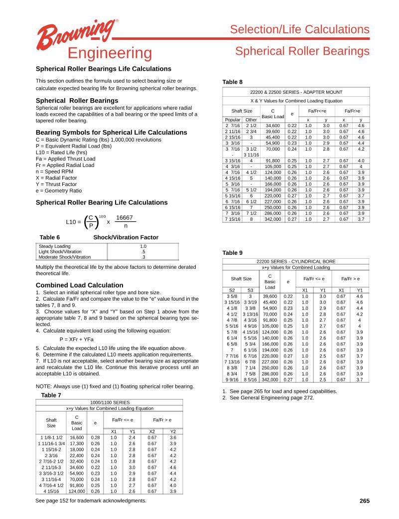
Spherical Roller BearingsSpherical Roller Bearings Life Calculations
This section outlines the formula used to select bearing size orcalculate expected bearing life for Browning spherical roller bearings.
Spherical Roller BearingsSpherical roller bearings are excellent for applications where radialloads exceed the capabilities of a ball bearing or the speed limits of atapered roller bearing.
Bearing Symbols for Spherical Life CalculationsC = Basic Dynamic Rating (lbs) 1,000,000 revolutionsP = Equivalent Radial Load (lbs)L10 = Rated Life (hrs)Fa = Applied Thrust LoadFr = Applied Radial Loadn = Speed RPMX = Radial FactorY = Thrust Factore = Geometry Ratio
Spherical Roller Bearing Life Calculations
Multiply the theoretical life by the above factors to determine deratedtheoretical life.
Combined Load Calculation1. Select an initial spherical roller type and bore size.2. Calculate Fa/Fr and compare the value to the “e” value found in thetables 7, 8 and 9.3. Choose values for “X” and “Y” based on Step 1 above from theappropriate table 7, 8 and 9 based on the spherical bearing type se-lected.4. Calculate equivalent load using the following equation:
P = XFr + YFa
5. Calculate the expected L10 life using the life equation above.6. Determine if the calculated L10 meets application requirements.7. If L10 is not acceptable, select another bearing size as appropriateand recalculate the L10 life. Continue this iterative process until anacceptable L10 is obtained.
NOTE: Always use (1) fixed and (1) floating spherical roller bearing.
Table 8
Table 9
Table 6 Shock/Vibration Factor
Table 71. See page 265 for load and speed capabilities.2. See General Engineering page 272.
L10 =16667
n( )CP
10/3
x
22200 & 22500 SERIES - ADAPTER MOUNT
X & Y Values for Combined Loading Equation
Shaft Size CBasic Load
eFa/Fr<=e Fa/Fr>e
Popular Other x y x y2 7/16 2 1/2 34,600 0.22 1.0 3.0 0.67 4.62 11/16 2 3/4 39,600 0.22 1.0 3.0 0.67 4.62 15/16 3 45,400 0.22 1.0 3.0 0.67 4.63 3/16 - 54,900 0.23 1.0 2.9 0.67 4.43 7/16 3 1/2 70,000 0.24 1.0 2.8 0.67 4.2
- 3 11/163 15/16 4 91,800 0.25 1.0 2.7 0.67 4.04 3/16 - 105,000 0.25 1.0 2.7 0.67 44 7/16 4 1/2 124,000 0.26 1.0 2.6 0.67 3.94 15/16 5 140,000 0.26 1.0 2.6 0.67 3.95 3/16 - 166,000 0.26 1.0 2.6 0.67 3.95 7/16 5 1/2 194,000 0.26 1.0 2.6 0.67 3.95 15/16 6 220,000 0.27 1.0 2.7 0.67 3.76 7/16 6 1/2 227,000 0.26 1.0 2.6 0.67 3.96 15/16 7 250,000 0.26 1.0 2.6 0.67 3.97 3/16 7 1/2 286,000 0.26 1.0 2.6 0.67 3.97 15/16 8 342,000 0.27 1.0 2.7 0.67 3.7
22200 SERIES - CYLINDRICAL BOREx+y Values for Combined Loading
Shaft Size CBasicLoad
eFa/Fr <= e Fa/Fr > e
S2 S3 X1 Y1 X1 Y13 5/8 3 39,600 0.22 1.0 3.0 0.67 4.6
3 15/16 3 3/19 45,400 0.22 1.0 3.0 0.67 4.64 1/8 3 3/8 54,900 0.23 1.0 2.9 0.67 4.44 1/2 3 13/16 70,000 0.24 1.0 2.8 0.67 4.24 7/8 4 3/16 91,800 0.25 1.0 2.7 0.67 45 5/16 4 9/16 105,000 0.25 1.0 2.7 0.67 45 7/8 4 15/16 124,000 0.26 1.0 2.6 0.67 3.96 1/4 5 5/16 140,000 0.26 1.0 2.6 0.67 3.96 5/8 5 3/4 166,000 0.26 1.0 2.6 0.67 3.9
7 6 1/16 194,000 0.26 1.0 2.6 0.67 3.97 7/16 6 7/16 220,000 0.27 1.0 2.5 0.67 3.77 13/16 6 7/8 227,000 0.26 1.0 2.6 0.67 3.98 3/8 7 1/4 250,000 0.26 1.0 2.6 0.67 3.98 3/4 7 5/8 286,000 0.26 1.0 2.6 0.67 3.99 9/16 8 5/16 342,000 0.27 1.0 2.5 0.67 3.7
Steady Loading 1.0Light Shock/Vibration .5Moderate Shock/Vibration .3
1000/1100 SERIESx+y Values for Combined Loading Equation
ShaftSize
CBasicLoad
eFa/Fr <= e Fa/Fr > e
X1 Y1 X2 Y21 1/8-1 1/2 16,600 0.28 1.0 2.4 0.67 3.6
1 11/16-1 3/4 17,300 0.26 1.0 2.6 0.67 3.91 15/16-2 18,000 0.24 1.0 2.8 0.67 4.2
2 3/16 22,400 0.24 1.0 2.8 0.67 4.22 7/16-2 1/2 32,400 0.24 1.0 2.8 0.67 4.22 11/16-3 34,600 0.22 1.0 3.0 0.67 4.6
3 3/16-3 1/2 54,900 0.23 1.0 2.9 0.67 4.43 11/16-4 70,000 0.24 1.0 2.8 0.67 4.2
4 7/16-4 1/2 91,800 0.25 1.0 2.7 0.67 4.04 15/16 124,000 0.26 1.0 2.6 0.67 3.9
266 See page 152 for trademark acknowledgments.
Engineering
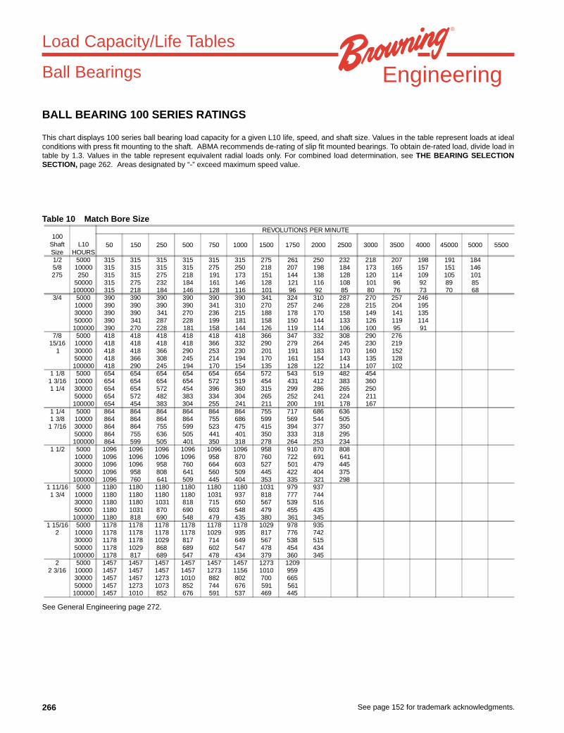
BALL BEARING 100 SERIES RATINGS
This chart displays 100 series ball bearing load capacity for a given L10 life, speed, and shaft size. Values in the table represent loads at idealconditions with press fit mounting to the shaft. ABMA recommends de-rating of slip fit mounted bearings. To obtain de-rated load, divide load intable by 1.3. Values in the table represent equivalent radial loads only. For combined load determination, see THE BEARING SELECTIONSECTION, page 262. Areas designated by “-” exceed maximum speed value.
Table 10 Match Bore Size
Load Capacity/Life Tables
See General Engineering page 272.
Ball Bearings
100ShaftSize
L10HOURS
REVOLUTIONS PER MINUTE
50 150 250 500 750 1000 1500 1750 2000 2500 3000 3500 4000 45000 5000 5500
1/2 5000 315 315 315 315 315 315 275 261 250 232 218 207 198 191 1845/8 10000 315 315 315 315 275 250 218 207 198 184 173 165 157 151 146275 250 315 315 275 218 191 173 151 144 138 128 120 114 109 105 101
50000 315 275 232 184 161 146 128 121 116 108 101 96 92 89 85100000 315 218 184 146 128 116 101 96 92 85 80 76 73 70 68
3/4 5000 390 390 390 390 390 390 341 324 310 287 270 257 24610000 390 390 390 390 341 310 270 257 246 228 215 204 19530000 390 390 341 270 236 215 188 178 170 158 149 141 13550000 390 341 287 228 199 181 158 150 144 133 126 119 114100000 390 270 228 181 158 144 126 119 114 106 100 95 91
7/8 5000 418 418 418 418 418 418 366 347 332 308 290 27615/16 10000 418 418 418 418 366 332 290 279 264 245 230 219
1 30000 418 418 366 290 253 230 201 191 183 170 160 15250000 418 366 308 245 214 194 170 161 154 143 135 128100000 418 290 245 194 170 154 135 128 122 114 107 102
1 1/8 5000 654 654 654 654 654 654 572 543 519 482 4541 3/16 10000 654 654 654 654 572 519 454 431 412 383 3601 1/4 30000 654 654 572 454 396 360 315 299 286 265 250
50000 654 572 482 383 334 304 265 252 241 224 211100000 654 454 383 304 255 241 211 200 191 178 167
1 1/4 5000 864 864 864 864 864 864 755 717 686 6361 3/8 10000 864 864 864 864 755 686 599 569 544 5051 7/16 30000 864 864 755 599 523 475 415 394 377 350
50000 864 755 636 505 441 401 350 333 318 295100000 864 599 505 401 350 318 278 264 253 234
1 1/2 5000 1096 1096 1096 1096 1096 1096 958 910 870 80810000 1096 1096 1096 1096 958 870 760 722 691 64130000 1096 1096 958 760 664 603 527 501 479 44550000 1096 958 808 641 560 509 445 422 404 375100000 1096 760 641 509 445 404 353 335 321 298
1 11/16 5000 1180 1180 1180 1180 1180 1180 1031 979 9371 3/4 10000 1180 1180 1180 1180 1031 937 818 777 744
30000 1180 1180 1031 818 715 650 567 539 51650000 1180 1031 870 690 603 548 479 455 435100000 1180 818 690 548 479 435 380 361 345
1 15/16 5000 1178 1178 1178 1178 1178 1178 1029 978 9352 10000 1178 1178 1178 1178 1029 935 817 776 742
30000 1178 1178 1029 817 714 649 567 538 51550000 1178 1029 868 689 602 547 478 454 434100000 1178 817 689 547 478 434 379 360 345
2 5000 1457 1457 1457 1457 1457 1457 1273 12092 3/16 10000 1457 1457 1457 1457 1273 1156 1010 959
30000 1457 1457 1273 1010 882 802 700 66550000 1457 1273 1073 852 744 676 591 561100000 1457 1010 852 676 591 537 469 445

267See page 152 for trademark acknowledgments.
Engineering
BALL BEARING 200 AND 300 SERIES RATINGS
This chart displays 200 and 300 series ball bearing load capacity for a given L10 life, speed, and shaft size. Values in the table represent loads atideal conditions with press fit mounting to the shaft. ABMA recommends de-rating of slip fit mounted bearings. To obtain de-rated load, divideload in table by 1.3. Values in the table represent equivalent radial loads only. For combined load determination, see THE BEARING SELECTIONSECTION, page 262. Areas designated by “-” exceed maximum speed value.
Table 11 Match Bore Size
Load Capacity/Life Tables
See General Engineering page 272.
Ball Bearings
SHAFT SIZES L10HOURS
REVOLUTIONS PER MINUTE200Dia.
Inches
300Dia.
Inches
50 150 250 500 750 1000 1500 1750 2000 2500 3000 3500 4000 4500 5000 5500 6500 7500
1/2 5000 500 500 500 397 347 315 275 261 250 232 218 207 198 191 184 178 169 1615/8 10000 500 470 397 315 275 250 218 207 198 184 173 165 157 151 146 142 134 128
30000 470 326 275 218 191 173 151 144 138 128 120 114 109 105 101 98 93 8950000 397 275 232 184 161 146 128 121 116 108 101 96 92 89 85 83 78 75100000 315 218 184 146 128 116 101 96 92 85 80 76 73 70 68 66 62 59
3/4 5000 619 619 619 491 429 390 341 324 310 287 270 257 246 236 228 221 20910000 583 583 491 390 341 310 270 257 246 228 215 204 195 188 181 175 16630000 583 404 341 270 236 215 188 178 170 158 149 141 135 130 126 122 11550000 491 341 287 228 199 181 158 150 144 133 126 119 114 110 106 103 97100000 390 270 228 181 158 144 126 119 114 106 100 95 91 87 84 81 77
7/8 5000 664 664 664 527 461 418 366 347 332 308 290 276 264 253 245 23715/16 10000 625 625 527 418 366 332 290 276 264 245 230 219 209 201 194 188
1 30000 625 433 366 290 253 230 201 191 183 170 160 152 145 139 135 13050000 527 366 308 245 214 194 170 161 154 143 135 128 122 118 114 110100000 418 290 245 194 170 154 135 128 122 114 107 102 97 93 90 87
1 1/8 1 5000 1039 1039 1039 825 720 654 572 543 519 482 454 431 412 3961 3/16 10000 978 978 825 654 572 519 454 431 412 383 360 342 327 3151 1/4 30000 978 678 572 454 396 390 315 299 286 265 250 237 227 218
50000 825 572 482 383 334 304 265 252 241 224 211 200 191 184100000 654 454 383 304 265 241 211 200 191 178 167 159 152 146
1 1/4 1 3/16 5000 1290 1290 1290 1088 951 864 755 717 686 636 599 569 5441 3/8 1 1/4 10000 1290 1290 1088 864 755 686 599 569 544 505 475 452 4321 7/16 30000 1290 895 755 599 523 475 415 394 377 350 330 313 299
50000 1088 755 636 505 441 401 350 333 318 295 278 264 253100000 864 599 505 401 350 318 278 264 253 234 221 210 200
1 1/2 1 7/16 5000 1638 1638 1638 1381 1207 1096 958 910 870 808 760 72210000 1638 1638 1381 1096 958 870 760 722 691 641 603 57330000 1638 1136 958 760 664 603 527 501 479 445 418 39750000 1381 958 808 641 560 509 445 422 404 375 353 335100000 1096 760 641 509 445 404 353 335 321 298 280 266
1 5/8 1 1/2 5000 1763 1763 1763 1487 1299 1180 1031 979 937 870 8181 11/16 10000 1763 1763 1487 1180 1031 937 818 777 744 690 650 1 3/4 30000 1763 1222 1031 818 715 650 567 539 516 479 450
50000 1487 1031 870 690 603 548 479 455 435 404 380100000 1180 818 690 548 479 435 380 361 345 320 301
1 15/16 1 11/16 5000 1760 1760 1760 1485 1297 1178 1029 978 935 868 8172 1 3/4 10000 1760 1760 1485 1178 1029 935 817 7769 742 689 649
30000 1760 1221 1029 817 714 649 567 538 515 478 45050000 1485 1029 868 689 602 547 478 454 434 403 379100000 1178 817 689 547 478 434 379 360 345 320 301
2 1 15/16 5000 2176 2176 2176 1835 1603 1457 1273 1209 1156 10732 3/16 2 10000 2176 2176 1835 1457 1273 1156 1010 959 918 852
30000 2176 1509 1273 1010 882 802 700 665 636 59150000 1835 1273 1073 852 744 676 591 561 537 498100000 1457 1010 852 676 591 537 469 445 426 395
2 1/4 2 3/16 5000 2631 2631 2631 2219 1938 1761 1538 1461 1398 12982 7/16 2 1/4 10000 2631 2631 2219 1761 1538 1398 1221 1160 1109 1030
30000 2631 1824 1538 1221 1067 969 847 804 769 71450000 2219 1538 1298 1030 900 817 714 678 649 602100000 1761 1221 1030 817 714 649 567 538 515 478
2 11/16 2 7/16 5000 3118 3118 3118 2629 2297 2087 1823 1732 16562 1/2 10000 3118 3118 2629 2087 1823 1656 1447 1375 1315
30000 3118 2162 1823 1447 1264 1149 1003 953 91250000 2629 1823 1538 1220 1066 969 846 804 769100000 2087 1447 1220 969 846 769 672 638 610
2 15/16 2 11/16 5000 3311 3311 3311 2793 2440 2217 1936 1839 175910000 3311 3311 2793 2217 1936 1759 1537 1460 139630000 3311 2296 1936 1537 1343 1220 1066 1012 96850000 2793 1936 1633 1296 1332 1029 899 854 817100000 2217 1537 1296 1029 899 817 713 678 648
2 15/16 5000 3885 3885 3885 3277 2863 2601 2272 2158 20643 10000 3885 3885 3277 2601 2272 2064 1803 1713 1639
30000 3885 2694 2272 1803 1575 1431 1250 1188 113650000 3277 2272 1916 1521 1329 1207 1055 1002 958100000 2601 1803 1521 1207 1055 958 837 795 761
3 7/16 5000 4812 4812 4812 4059 3546 3222 2814 26733 1/2 10000 4812 4812 4059 3222 2814 2557 2234 2122
30000 4812 3337 2814 2234 1951 1773 1549 147150000 4059 2814 2374 1884 1646 1495 1306 1241100000 3222 2234 1884 1495 1306 1187 1037 985
3 15/16 5000 6673 6673 6673 5628 4917 4467 3902 10000 6673 6673 5628 4467 3902 3546 309730000 6673 4627 3902 3097 2706 2458 214850000 5628 3902 3291 2612 2282 2074 1811100000 4467 3097 2612 2074 1811 1646 1438

268 See page 152 for trademark acknowledgments.
EngineeringTAPERED ROLLER BEARINGS 900 AND 950 SERIESThis chart displays the Browning 900 and 950 Series Tapered Roller Bearing’s load capacity for a given L10 life, speed and shaft size. Values inthe table represent loads at ideal conditions. The shaded areas indicate the maximum speed for the 950 series only. Select 950 Series wherealigning capability is required. For combined load determination, see THE BEARING SELECTION SECTION, page 264. Areas designated by“-” exceed maximum speed value.
Table 12 Match Bore Size
Load Capacity/Life Tables
See General Engineering page 272.
Roller Bearings
SIZE"K"
FACTOR
"C"2 ROWRATING
1 ROWRATING
THRUSTRATING*
L10HOURS
REVOLUTIONS PER MINUTE
50 100 150 250 500 750 1000 1500 1750 2000 2500 3000 35001 1.42 3700 2130 1500 5000 4179 4179 4179 3908 3174 2811 2578 2283 2180 2094 1959 1854 1771
10000 4179 4179 3700 3174 2578 2283 2094 1854 1771 1701 1591 1506 143830000 3700 3005 2611 2283 1854 1642 1506 1334 1273 1223 1144 1083 103450000 3174 2578 2283 1959 1591 1409 1292 1144 1093 1050 982 929 887100000 2578 2094 1854 1591 1292 1144 1050 929 887 853 797 755 721
1 3/16 1.53 5130 2950 1930 5000 5794 5794 5794 5418 4401 3897 3575 3165 3022 2904 2716 2571 24551 1/4 10000 5794 5794 5130 4401 3575 3165 2904 2571 2455 2358 2206 2088 19441 3/8 30000 5130 4167 3690 3165 2571 2277 2088 1849 1766 1696 1586 1502 1434
50000 4401 3575 3165 2716 2206 1953 1792 1586 1515 1455 1361 1289 1230100000 3575 2904 2571 2206 1792 1586 1455 1289 1230 1182 1106 1047 999
1 7/16 1.46 5930 3410 2330 5000 6697 6697 6697 6263 5087 4505 4132 3659 3494 3356 3139 29721 1/2 10000 6697 6697 5930 5087 4132 3659 3356 2972 2838 2726 2550 2414
30000 5930 4817 4265 3659 2972 2632 2414 2138 2041 1961 1834 173650000 5087 4132 3659 3139 2550 2258 2071 1834 1751 1682 1573 1490100000 4132 3356 2972 2550 2071 1834 1682 1490 1422 1366 1278 1210
1 5/8 1.37 6050 3470 2540 5000 6833 6833 6833 6390 5190 4596 4216 3733 3564 3424 32031 11/16 10000 6833 6833 6050 5190 4216 3733 3424 3032 2895 2781 26011 3/4 30000 6050 4914 4351 3733 3032 2685 2463 2181 2082 2000 1871
50000 5190 4216 3733 3203 2601 2303 2113 1871 1786 1716 1605100000 4216 3424 3032 2601 2113 1871 1716 1520 1451 1394 1304
1 7/8 1.65 8550 4910 2980 5000 9656 9656 8656 9031 7335 6495 5958 5276 5037 48391 15/16 10000 9656 9656 8550 7335 5958 5276 4839 4285 4091 3931
2 30000 8550 6945 6149 5276 4285 3794 3481 3082 2943 28272 1/8 50000 7335 5958 5276 4526 3676 3255 2986 2644 2525 2425
100000 5958 4839 4285 3676 2986 2644 2425 2148 2051 19702 3/16 1.51 9090 5220 3470 5000 10266 10266 10266 9601 7798 6905 6334 5609 5355 5145
10000 10266 10266 9090 7798 6334 5609 5145 4556 4350 417930000 9090 7383 6538 5609 4556 4034 3700 3277 3129 300650000 7798 6334 5609 4812 3908 3461 3175 2811 2684 2579100000 6334 5145 4556 3908 3175 2811 2579 2283 2180 2095
2 1/4 1.45 9290 5340 3670 5000 10492 10492 10492 9812 7970 7057 6474 5732 54732 7/16 10000 10492 10492 9290 7970 6474 5732 5258 4656 44462 1/2 30000 9290 7546 6682 5732 4656 4123 3782 3349 3197
50000 7970 6474 5732 4918 3994 3537 3245 2873 2743100000 6474 5258 4656 3994 3245 2873 2635 2334 2228
2 11/16 1.30 9600 5510 4260 5000 10842 10842 10842 10140 8236 7293 6690 59242 3/4 10000 10842 10842 9600 8236 6690 5924 5434 4811
2 15/16 30000 9600 7798 6905 5924 4811 4260 3908 346050000 8236 6690 5924 5082 4128 3655 3353 2969100000 6690 5434 4811 4128 3353 2969 2723 2411
3 1.31 14500 8330 6340 5000 16376 16376 16376 15315 12440 11015 101043 3/16 10000 16376 16378 14500 12440 10104 8947 8207
30000 14500 11778 10429 8947 7267 6435 590350000 12440 10104 8947 7676 6235 5521 5064100000 10104 8207 7267 6235 5064 4484 4113
3 7/16 1.19 15300 8790 7410 5000 17279 17279 17279 16160 13126 11623 106623 1/2 10000 17279 17279 15300 13126 10662 9441 8660
30000 15300 12427 11004 9441 7668 6790 622850000 13126 10104 9441 8099 6579 5825 5344100000 10662 8207 7668 6579 5344 4732 4340
3 15/16 1.45 18400 10600 7270 5000 20780 20780 20780 19434 15786 13978 128224 10000 20780 20780 18400 15786 12822 11353 10415
30000 18400 14945 13234 11353 9222 8166 749050000 15786 12822 11353 9740 7912 7005 6426100000 12822 10415 9222 7912 6426 5690 5220
4 7/16 1.91 25200 14500 7550 5000 28460 28460 28460 26617 21620 19143 175614 1/2 10000 28460 28460 25200 21620 17561 15549 14264
30000 25200 20469 18124 15549 12630 11183 1025950000 21620 17561 15549 13340 10835 9594 8801100000 17561 14264 12630 10835 8801 7793 7149
4 15/16 1.82 26600 15300 8390 5000 30041 30041 30041 28095 22821 202075 10000 30041 30041 26600 22821 18536 16413
30000 26600 21606 19131 16413 13332 1180550000 22821 18536 16413 14081 11437 10127100000 18536 15056 13332 11437 9290 8226

269See page 152 for trademark acknowledgments.
EngineeringTAPERED ROLLER BEARINGS 920 AND 970 SERIES
This chart displays the Browning 920 and 970 Series Tapered Roller Bearing’s load capacity for a given L10 life, speed and shaft size. Values inthe table represent loads at ideal conditions. The shaded areas indicate the maximum speed for the 970 series only. For combined loaddetermination, see THE BEARING SELECTION SECTION, page 264. Areas designated by “-” exceed maximum speed value.
Table 13 Match Bore Size
Load Capacity/Life Tables
See General Engineering page 272.
Roller Bearings
SIZE"K"
FACTOR
"C"2 ROWRATING
1 ROWRATING
THRUSTRATING* HOURS
REVOLUTIONS PER MINUTE
50 100 150 250 500 750 1000 1500 1750 2000 2500 3000 3500 40001 3/16 1.23 2975 1710 1390 5000 3360 3360 3360 3142 2552 2260 2073 1836 1753 1684 1575 1491 1424 13681 1/4 10000 3360 3360 2975 2552 2073 1836 1684 1491 1424 1368 1279 1211 1156 1111
30000 2975 2416 2140 1836 1491 1320 1211 1072 1024 984 920 871 832 79950000 2552 2073 1836 1575 1279 1133 1039 920 878 844 789 747 714 685100000 2073 1684 1491 1279 1039 920 844 747 714 685 641 607 580 556
1 3/8 1.31 4760 2740 2080 5000 5376 5376 5376 5028 4084 3616 3317 2937 2804 2694 2520 2386 22781 7/16 10000 5376 5376 4760 4084 3317 2937 2694 2386 2278 2188 2047 1938 1850
30000 4760 3866 3424 2937 2386 2112 1938 1716 1638 1574 1472 1394 133150000 4084 3317 2937 2520 2047 1812 1662 1472 1406 1350 1263 1196 1142100000 3317 26741 2386 2047 1662 1472 1350 1196 1142 1097 1026 971 927
1 1/2 1.36 6140 3530 2600 5000 6934 6934 6934 6485 5268 4664 4279 3789 3617 3475 3250 30771 11/16 10000 6934 6934 6140 5268 4279 3789 3475 3077 2938 2823 2640 2500
30000 6140 4987 4416 3789 3077 2725 2500 2213 2113 2030 1899 179850000 5268 4279 3789 3250 2640 2338 2144 1899 1813 1742 1629 1542100000 4279 3475 3077 2640 2144 1899 1742 1542 1473 1415 1323 1253
1 3/4 1.83 8070 4640 2540 5000 9114 9114 9114 8524 6923 6130 5624 4979 4754 4568 42721 15/16 10000 9114 9114 8070 6923 5624 4979 4568 4045 3862 3710 3470
2 30000 8070 6555 5804 4979 4045 3581 3285 2909 2777 2668 249650000 6923 5624 4979 4272 3470 3072 2818 2496 2383 2289 2141100000 5624 4568 4045 3470 2818 2496 2289 2027 1935 1859 1739
2 3/16 1.65 8570 4910 2980 5000 9679 9679 9679 9052 7352 6510 5972 5288 5049 4851 453710000 9679 9679 8570 7352 5972 5288 4851 4295 4101 3940 368530000 8570 6961 6164 5288 4295 3803 3489 3089 2950 2834 265050000 7352 5972 5288 4537 3685 3263 2993 2650 2530 2431 2274100000 5972 4851 4295 3685 2993 2650 2431 2153 2055 1975 1847
2 1/4 1.51 9030 5220 3470 5000 10198 10198 10198 9538 7747 6860 6293 5572 5320 51112 7/16 10000 10198 10198 9030 7747 6293 5572 5111 4526 4321 41522 1/2 30000 9030 7335 6495 5572 4526 4007 3676 3255 3108 2986
50000 7747 6293 5572 4780 3883 3438 3154 2793 2666 2562100000 6293 5111 4526 3883 3154 2793 2562 2268 2166 2081
2 11/16 1.30 9630 5510 4260 5000 10876 10876 10876 10171 8262 7316 6711 5942 56742 15/16 10000 10876 10876 9630 8262 6711 5942 5451 4826 4608
3 30000 9630 7822 6926 5942 4826 4274 3920 3471 331450000 8262 6711 5942 5098 4141 3666 3363 2978 2843100000 6711 5451 4826 4141 3363 2978 2732 2419 2310
3 3/16 1.19 15320 8790 7410 5000 17302 17302 17302 16181 13143 11638 10676 94533 7/16 10000 17302 17302 15320 13143 10676 9453 8671 76783 1/2 30000 15320 12444 11018 9453 7678 6799 6273 5522
50000 13143 10676 9453 8110 6587 5833 5351 4738100000 10676 8671 7678 6587 5351 4738 4346 3848
3 15/16 1.23 20980 12100 9800 5000 23694 23694 23694 22159 17999 15938 14620 129454 10000 23694 23694 20980 17999 14620 12945 11875 10515
30000 20980 17041 15089 12945 10515 9311 5841 756350000 17999 14620 12945 11106 9021 7988 7327 6488100000 14620 11875 10515 9021 7327 6488 5952 5270
4 7/16 1.13 25750 14800 13100 5000 29081 29081 29081 27198 22091 19561 179444 1/2 10000 29081 29081 25750 22091 17944 15889 14575
30000 25750 20915 18520 15889 12906 11427 1048350000 22091 17944 15889 13631 11072 9804 8993100000 17944 14575 12906 11072 8993 7963 7305
4 15/16 1.27 35520 20400 16000 5000 40114 40114 40114 37517 30473 26983 247525 10000 40114 40114 35520 30473 24752 21917 20105
30000 35520 28851 25547 21917 17802 15763 1446050000 30473 24752 21917 18803 15273 13524 12405100000 24752 20105 17802 15273 12405 10985 10076

270 See page 152 for trademark acknowledgments.
Engineering
SPHERICAL ROLLER BEARINGS 1000 AND 1100 SERIES
This chart displays the Browning 1000 and 1100 Series Spherical Roller Bearing’s load capacity for a given L10 life, speed and shaft size. Valuesin the table represent loads at ideal conditions. The shaded areas indicate the maximum speed for the MULTI-TRAP Seal. The maximum speedfor the Contact Seal is indicated in the non-shaded areas. For combined load determination, see THE BEARING SELECTION SECTION, page265. Areas designated by “-” exceed maximum speed value.
Table 14 Match Bore Size
Load Capacity/Life Tables
See General Engineering page 272.
Roller Bearings
Size RatingL10
HoursREVOLUTIONS PER MINUTE
50 100 150 250 500 750 1000 1500 1750 2000 2500 3000 35001 1/8 16600 5000 4880 4880 4880 4546 3692 3269 2999 2656 2535 2436 2278 2157 20591 3/16 10000 4880 4860 4304 3692 2999 2656 2436 2157 2059 1979 1850 1752 16731 1/4 30000 4304 3496 3095 2656 2157 1910 1752 1551 1481 1423 1331 1260 12031 7/16 50000 3692 2999 2656 2278 1850 1639 1503 1331 1271 1221 1142 1081 10321 1/2 100000 3999 2436 2157 1850 1503 1331 1221 1081 1032 992 927 878 838
1 11/16 17300 5000 5090 5090 5090 4737 3848 3407 3125 2767 2642 2539 2374 2248 21461 3/4 10000 5090 5065 4485 3848 3125 2767 2539 2248 2146 2062 1929 1826 1743
30000 4485 3643 3226 2767 2248 1990 1826 1617 1544 1483 1387 1313 125450000 3848 3125 2767 2374 1929 1708 1566 1387 1324 1272 1190 1127 1076100000 3125 2539 2248 1929 1566 1387 1272 1127 1076 1033 967 915 874
1 15/16 18000 5000 5290 5290 5290 4929 4004 3545 3252 2879 2749 2641 2470 2339 22332 10000 5290 5270 4667 4004 3252 2879 2641 2339 2233 2145 2007 1900 1814
30000 4667 3790 3356 2879 2339 2071 1900 1682 1606 1543 1443 1366 130550000 4004 3252 2879 2470 2007 1777 1630 1443 1378 1324 1238 1172 1119100000 3252 2641 2339 2007 1630 1443 1324 1172 1119 1075 1006 952 909
2 3/16 22400 5000 6590 6590 6590 6134 4982 4412 4047 3583 3421 3287 3074 2911 277910000 6590 6559 5807 4982 4047 3583 3287 2911 2779 2670 2497 2364 225730000 5807 4717 4177 3583 2911 2577 2364 2093 1999 1920 1796 1700 162350000 4982 4047 3583 3074 2497 2211 2028 1796 1715 1647 1541 1459 1393100000 4047 3287 2911 2497 2028 1796 1647 1459 1393 1338 1251 1185 1131
2 7/16 32400 5000 9530 9530 9530 8872 7206 6381 5853 5183 4949 4754 4447 42102 1/2 10000 9530 9486 8400 7206 5853 5183 4754 4210 4020 3682 3612 3420
30000 8400 6823 6041 5183 4210 3728 3420 3028 2891 2778 2598 245950000 7206 5853 5183 4447 3612 3198 2934 2598 2480 2383 2229 2110100000 5853 4754 4210 3612 2934 2598 2383 2110 2015 1936 1810 1714
2 11/16 34600 5000 10175 10175 10175 9475 7696 68144 6251 5535 5285 5077 4749 44962 3/4 10000 10175 10131 8970 7696 6251 5535 5077 4496 4293 4124 3857 3652
2 15/16 30000 8970 7286 6452 5535 4496 3981 3652 3233 3087 2966 2774 26263 50000 7696 6251 5535 4749 3857 3415 3133 2774 2649 2545 2380 2253
100000 6251 5077 4496 3857 3133 2774 2545 2253 2151 2067 1933 18303 3/16 54900 5000 16150 16150 16150 15033 12211 10812 9918 8782 8385 80563 7/16 10000 16150 16074 14233 12211 9918 8782 8056 7133 6811 65443 1/2 30000 14233 11561 10237 8782 7133 6316 5794 5131 4899 4706
50000 12211 9918 8782 7535 6120 5419 4971 4402 4203 4038100000 9918 8056 7133 6120 4971 4402 4038 3575 3414 3280
3 11/16 70000 5000 20590 20590 20590 19168 15569 13786 12646 1198 10692 102723 15/16 10000 20590 20495 18148 15569 12646 11198 10272 9096 8684 8343
4 30000 18148 14741 13052 11198 9096 8054 7388 6542 6246 600150000 15569 12646 11198 9607 7803 6909 6338 5612 5359 5148100000 12646 10272 9096 7803 6338 5612 5148 4559 4353 4182
4 7/16 91800 5000 27000 27000 27000 25138 20418 18080 165854 1/2 10000 27000 26878 23800 20148 16585 14685 13471
30000 23800 19331 17117 14685 11928 10562 968950000 20418 16585 14685 12599 10233 9061 8312100000 16585 13471 11928 10233 8312 7360 6751
4 15/16 124,000 5000 36470 36470 36470 33955 27580 2442110000 36470 36306 32148 27580 22402 1983630000 32148 26112 23121 19836 16112 1426750000 27580 22402 19836 17018 13823 12240100000 22402 18196 16112 13823 11228 9942

271See page 152 for trademark acknowledgments.
Engineering
SPHERICAL ROLLER BEARINGS 22200 AND 22500 SERIESThis chart displays the Browning 22200 and 22500 Series Spherical Roller Bearing’s load capacity for a given L10 life, speed and shaft size.Values in the table represent loads at ideal conditions. For combined load determination, see THE BEARING SELECTION SECTION, page 265.Areas designated by “-” exceed maximum speed value.
Table 15 Match Bore Size
Load Capacity/Life Tables
See General Engineering page 272.
Roller Bearings
Size RatingL10
HoursREVOLUTIONS PER MINUTE
50 100 150 250 500 750 1000 1500 1750 2000 2500 3000 350022515 34600 5000 10131 10131 10131 9475 7696 6814 6251 5535 5285 5077 4749 4496
10000 10131 1013 8970 7696 6251 5535 5077 4496 4293 4124 3857 365230000 8970 7286 6452 5535 4496 3981 3652 3233 3087 2966 2774 262650000 7696 6251 5535 4749 3857 3415 3133 2774 2649 2545 2380 2253100000 6251 5077 4496 3857 3133 2774 2545 2253 2151 2067 1933 1830
22516 39600 5000 11595 11595 11595 10844 8808 7799 7154 6335 6049 5811 5435 514510000 11595 11595 10267 8808 7154 6335 5811 5145 4913 4720 4414 417930000 10267 8339 7384 6335 5145 4556 4179 3701 3533 3395 3175 300650000 8808 7154 6335 5435 4414 3909 3586 3175 3031 2912 2724 2579100000 7154 5811 5145 4414 3586 3175 2912 2579 2462 2366 2212 2095
22517 45400 5000 13293 13293 13293 12432 10098 8941 8202 7263 6934 6662 6231 589910000 13293 13293 11770 10098 8202 7263 6662 5899 5633 5411 5061 479230000 11770 9560 8465 7263 5899 5229 4792 4243 4051 3892 3640 344650000 10098 8202 7263 6231 5061 4481 4111 3640 3475 3339 3123 2957100000 8202 6662 5899 5061 4111 3640 3339 2957 2823 2712 2536 2401
22518 54900 5000 16074 16074 16074 15033 12211 10812 9918 8782 8385 8056 753510000 16074 16074 14233 12211 9918 8782 8056 7133 6811 6544 612030000 14233 11561 10237 8782 7133 6316 5794 5131 4899 4706 440250000 12211 9918 8782 7535 6120 5419 4971 4402 4203 4038 3776100000 9918 8056 7133 6120 4971 4402 4038 3575 3414 3280 3067
22520 70000 5000 20495 20495 20495 19168 15569 13786 12646 11198 10692 1027210000 20495 20495 18148 15569 12646 11198 10272 9096 8684 834330000 18148 14741 13052 11198 9096 8054 7388 6542 6246 600150000 15569 12646 11198 9607 7803 6909 6338 5612 5359 5148100000 12646 10272 9096 7803 6338 5612 5148 4559 4353 4182
22522 91800 5000 26878 26878 26878 25138 204018 18080 16585 14685 14022 1347110000 26878 26878 23800 20418 16585 14685 13471 11928 11389 1094230000 23800 19331 17117 14685 11928 10562 9689 8579 8191 787050000 20418 16585 14685 12599 10233 9061 8312 7360 7027 6751100000 16585 13471 11928 10233 8312 7360 6751 5978 5708 5484
22524 105000 5000 30743 30743 30743 28752 23354 20679 18969 16797 1603810000 30743 30743 27222 23354 18969 16797 15408 13643 1302730000 27222 22111 19579 16797 13643 12081 11082 9813 963950000 23354 18969 16797 14410 11705 10364 9507 8418 8038100000 18969 15408 13643 11705 9507 8418 7722 6838 6529
22526 124000 5000 36306 36306 36306 33955 27580 24421 22402 19836 1894010000 36306 36306 32148 27580 22402 19836 18196 16112 1538430000 32148 26112 23121 19836 16112 14267 13087 11588 1106450000 27580 22402 19836 17018 13823 12240 11228 9942 9492100000 22402 18196 16112 13823 11228 9942 9120 8075 7710
22528 140000 5000 40991 40991 40991 38336 31139 27572 25293 2239610000 40991 40991 36296 31139 25293 22396 20544 1819130000 36296 29481 26105 22396 18191 16108 14776 1308350000 31139 25293 22396 19214 15606 13819 12676 11244100000 25293 20544 18191 15606 12676 1124 10296 9117
22530 166000 5000 48603 48603 48603 45456 36922 3293 29990 2655510000 48603 48603 43037 36922 29990 26555 24359 2156930000 43037 34957 30953 26555 21569 19099 17520 1551350000 36922 29990 26555 22782 18505 16385 15031 13309100000 29990 24359 21569 18505 15031 13309 12209 10810
22532 194000 5000 56801 56801 56801 53123 43150 38208 35048 3103410000 56801 56801 50296 43150 35048 31034 28468 2520830000 50296 40853 36174 31034 25208 22321 20475 1813050000 43150 35048 31034 26625 21626 19149 17566 15554100000 35048 28468 25208 21626 17566 15554 14268 12634
22534 220000 5000 64414 64414 64414 60243 48933 43328 3974610000 64414 64414 57036 48933 39746 35193 3228330000 57036 46328 41022 35193 28586 25312 2321950000 48933 39746 35193 30193 24524 21716 19920100000 39746 32283 28586 24524 19920 17638 16180
22536 227000 5000 66463 66463 66463 62160 50489 44707 4101010000 66463 66463 58851 50489 41010 36313 3331130000 58851 47802 42327 36313 29495 26117 2395850000 50489 41010 36313 31154 25305 22406 20554100000 41010 33311 29495 25305 20554 18200 16695
22538 250000 5000 73198 73198 73198 68458 55605 49237 4516510000 73198 73198 64814 55605 45165 39993 3668630000 64814 52645 46616 39993 32484 28764 2638550000 55605 45165 39993 34310 27869 24677 22636100000 45165 36686 32484 27869 22636 20044 18386
22540 286000 5000 83738 83738 83738 78316 63612 56327 5166910000 83738 83738 74147 63612 51669 45751 4196830000 74147 60226 53329 45751 37162 32905 3018550000 63612 51669 45751 39251 31882 28230 25896100000 516694 41968 37162 31882 25896 22930 21034
22544 342000 5000 100134 100134 100134 93651 76068 6735610000 100134 100134 88666 76068 61786 5471030000 88666 72019 63770 54710 44438 3934950000 76068 61786 54710 46936 38124 33758100000 61786 50186 44438 38124 30967 27420

272 See page 152 for trademark acknowledgments.
Engineering
General Engineering
BEARING SELECTION:
Consult EPT Mounted Bearing Technical Support for
1. Moderate to High Thrust Load Applications
2. Housing Strength and Capabilities
3. High Load/High Speed Applications
4. See Bearing Dimension/Data Tables for General Bearing Capabilities
LINEAL SHAFT EXPANSION
Lineal shaft expansion is the change in length of a shaft due to a relative change in its temperature.For steelshafts, lineal expansion can be calculated using the following formula:
Expansion (Growth) = .0000063 x Length (inches) x Temperature Change °F
The following Roller Bearings can accommodate shaft lineal expansion as listed in the table below.
Table 16
Consult EPT Mounted Bearing Tech Support for applications where lineal expansion is a factor on other types ofBrowning Bearing Products or the lineal expansion exceeds the capability of the Roller Bearings listed above.
BEARING ALIGNMENT CAPABILITY (IN)ALLOWABLE ALIGNMENT ERROR (IN)Table 17
* Ball except cylindrical O. D. inserts
SEALS
• 900/950 series bearings are designed with metal labyrinth seals. Labyrinth seals rely on frequent lubrication forfull effectiveness. 920 and 970 series bearings with contact seals should be selected in moist, wet or highlycontaminated environments.
• 1000/1100 series are standard with metal labyrinth seals. Labyrinth seals rely on frequent lubrication for fulleffectiveness. Contact seals should be specified in moist, wet or highly contaminated environments.
Series Lineal Expansion Capability950, 970 .310 inched
1000, 1100, thru 1-3/4" .050 inches1000/1100 1-15/16 up .080 inches
22200/22500 .080 inches
DISTANCE BETWEEN BEARINGS (feet)
1 Ft. 2 Ft. 3 Ft. 4 Ft. 5 Ft. 6 Ft. 7 Ft. 8 Ft. 9 Ft. 10 Ft.
Labyrinth(Multi-trap)1000/1100
950/970/Ball *
.3 0.6 .9 1.3 1.6 1.9 2.2 2.5 2.8 3.63
Contact(Double Lip)1000/1100
.25 .5 .8 1.0 1.3 1.6 1.8 2.1 2.4 2.6
22500 (LER)22200 (LER)
.05 .1 .2 .2 .3 .3 .4 .4 .5 .5

273See page 152 for trademark acknowledgments.
Engineering
Application Worksheet
EMERSON POWER TRANSMISSIONEPT MOUNTED BEARING DIVISION
Mail To: EPT Bearing Operations - Application Engineering
1901 Bilter Rd.Aurora IL 60507
Fax to: Application Engineering 630-898-6064
Distributor Information Customer Information
Distributor Name Company Name
Contact Name Contact Name
Street Address Street Address
City/State/Zip City/State/Zip
Phone Phone
Fax Fax
E-Mail E-Mail
Is the Customer an: OEM or End User Industry
Application Information
Is this a new application Yes or No Complete Climate Description
Speed: EXPLAIN: Climate Conditions: Wet ❑
(rpm) Washdown ❑
Service Life Required: Dry ❑
(hours): Clean ❑
Dirty ❑
Shaft Diameter: Chemicals ❑
Load Information (lbs.): Load Conditions: Steady ❑ Operating Temperature (°F):
Radial (lbs.): Shock ❑ Is the bearing in the elevated temp? Yes / No
Axial / Thrust (lbs.): Thrust ❑ Is the heat coming through the shaft? Yes / No
Oscillation ❑
If loads unknown attach detailed sketch*** Other ❑ Can the bearings be re-lubricated? Yes ❑ No ❑
Complete Application Description: MotorHorsepower (bhp):
Driven PulleyDiameter (in.):
Distance Between Bearings:
***PLEASE ATTACH DETAILED SKETCH OF APPLICATION.
INCLUDE ALL DIMENSIONS AND SYSTEM LOAD LOCATIONS

274 See page 152 for trademark acknowledgments.
Engineering
L10 = (single row load rating)10/3
x500 x 3000
P n
LNA
=.456 x(11789)3
x 16667
= 2720 hours1660 1000
L10 = (5220)10/3
x3000 x 500
= 61,900 hrs. 1710 1000
L10 = (9030)10/3
x 500 x 3,000
= 959,000 hrs. 1300
1000
For moderate shock (from table 5) L10 = .5* 959,000 = 480,000 hrs*
Question # 2:What is the adjusted bearing life (L10 hours) for an VPS-39 BrowningBall Bearing with moderate shock conditions and the same applicationcriteria from above?
Solution:1. From Table 2 on page 262: a3 = 0.5 x 0.456.2. Re-Apply the life adjustment factors to the previously
calculated L10 life:Lna hours = L10 x a1 x a2 x a3
Lna hours = 12,430 x 1 x 1 x (0.5 x 0.456)Lna hours = 2,830 hours*
Question # 3:What is the bearing life (L10 hours) for an PB-970NEx 2 7/16 TaperedRoller Bearing with no shock conditions and the same application criteriafrom above?
Solution:1. Begin with the L10 life formula: L10 = (C/P)10/3 x 500 x 3,000
n
APPLICATION EXAMPLES:EXAMPLE # 1
Pure Radial LoadQuestion # 1:What is the adjusted bearing life (Lna hours) for an VPS-239 BrowningBall Bearing with no shock conditions and the following applicationcriteria?
Design Load (P) = 1300 lbs.Speed (n) = 1000 RPMShaft Size = 27/16 InchesOperating Temperature = 125°F
Solution:1. Begin with the L10 life formula: L10 = (C/P)3 x 16667
nLook up the insert of an VPS-239 on page 6. From Table 4 onpage 265, the Basic Dynamic Radial Rating is 11,789 lbs.
2. Apply the life adjustment factors:L
na hours = L
10 x a
1 x a
2 x a
3
Lna
hours = 12,430 x 1 x 1 x 0.456L
na hours = 5,700 hours *
2. PB-970NEx 2 7/16 has 2 7/16” shaft size. From Table 13 x onpage 269, the Radial Rating is 9,030 lbs.
Question # 4:What is the bearing life (L10 hours) for an SPB-1000NEx 2 7/16 SphericalRoller Bearing with moderate shock conditions and the same applicationcriteria from above?
Solution:1. From Table No. 14 on page 270:
L10 = ? x(32,400)10/3
x
16,667 = 754,000* hrs.
1300
1000
EXAMPLE # 2 Combined Radial and Thrust Load
Question # 1:What is the adjusted bearing life (Lna hours) for an VPS-239 BrowningBall Bearing with no shock conditions and the following applicationcriteria?
Design Radial Load (Fr) = 500 lbs.Design Thrust Load (Fa) = 1000 lbs.Speed (n) = 1000 RPMShaft Size = 27/16 InchesOperating Temperature = 125°F
Solution:1. Calculate Fa/Fr = 1000/500 = 22. Begin by calculating the Relative Axial Load (RAL):
(From Table 3, page 263)
RAL = Fa = 1000 = 251 lbs. ND2 3.9690
3. From Table 3 on page 263, interpolate RAL between200.10 and 300.15 and “e” between 0.30 and 0.34 to obtain
an “e” value:
251 - 200.10 = e - 0.30 Therefore e=.32300.15 - 200.10 0.34 - 0.30
4. From Table 3 on page 263, determine the value of “X”and “Y” through interpolation. Interpolate “e” between 0.30and 0.34 and “Y” between 1.45 and 1.31 because Fa/Fr > e;
0.32 - 0.30 = Y - 1.45 0.34 - 0.30 1.31 - 1.45Therefore Y = 1.38
X = .56
5. Determine the equivalent radial load (P):P = (X F
r) + (Y F
a)
= (0.56 x 500) + (1.38 x 1000) = 1660 lbs.
L10 = (C/P)3 x 16667
nLook up the insert of an VPS-239 on page 6. From Table 4 onpage 263, the Basic Dynamic Radial Rating is 11,789 lbs.
Question # 2:What is the bearing life (L10 hours) for an PB-970NEx 2 7/16 TaperedRoller Bearing with no shock conditions and the same application criteriafrom above?Solution:
1. Find the K factor value from Table 13 on page 269, K = 1.51.2. Calculate the internal thrust reaction (FIR):
FIR =0.6 x Fr -applied radial load
K -factor K in Table 13
FIR =0.6 x 500
= 199 lbs. 1.51
3. Since the thrust load is greater than the internal thrustreaction (FIR) use the following formula from page 264 tocalculate the equivalent radial load.
P = (0.4 x Fr) + (K x Fa)P = (0.4 X 500) + (1.51 X 1000) = 1710 lbs.
4. Caclulate the expected L10 life using the single row rating.Single row rating = 5,220 lbs. This is found in Table 13 onpage 269.
For moderate shock (from Table 6 page 265)L10 = .5 x 754,000 = 37,000 hrs*
* Excessively high or low hours are not realistic in applications.
Sample Calculations
L10 = (11789)3
x 16667
= 12,430 hours 1300
1000

275See page 152 for trademark acknowledgments.
Engineering
Sample Calculations
COMPUTING BEARING LOADS:
In the computation of bearing loads in any application of a Browning unit, the principal factor determining the selection of the unit isthe equivalent radial load to which the bearing will be subjected. These radial loads result from any one or any combination of thefollowing sources:
1. Weights of machine parts supported by bearings.2. Tension due to belt or chain pull.3. Centrifugal force from out of balance, eccentric or cam action.
The resulting load from any one, or any combination of the above sources is further determined by knowing:
1. The magnitude of the load.2. Direction of the load.3. The point of load application.4. The distance between bearing centers.
Bearing loads are the result of force acting on the shaft. Direction, magnitude, and location with respect to the bearings must be consideredwhen calculating bearing loads. The following cases are typical examples of loads encountered and methods of calculating bearing loads.
CASE # 1Straddle Mount Fan, Cantilever Drive
CASE # 3Straddle, Cantilever Fan, Cantilever Drive
Load on Bearing A =
= = 323 lbs.
Load on Bearing B =
=
= 827 lbs.
(P1 x b) - (P2 x c)
k
(P1 x a) + (c + k) x (P2)
k
(1,000 x 7) + (3 + 11) x (150)
11
(1,000 x 4) - (150 x 3)
11
Load on Bearing A =
=
= 137 lbs.
Load on Bearing B =
=
= 173 lbs.
P1 x (k + a) + (P
2 x c) - (P
3 x d)
k
-(P1 x a) + (P2 x b) + P3 x (k + d)
k
-(60 x 2) + (180 x 6) + 70 x (12 + 4)
12
60 x (12 + 2) + (180 x 6) - (70 x 4)
12
CASE # 2Cantilever Fan and Drive
CASE # 4Drive Load Calculation
Load on Bearing A =
= = 271 lbs.
Load on Bearing B =
=
= 9 lbs.
P1 x (a + k) - (P2 x b)
k
(P2 x (k + b) - (P1 x a)
k
80 x (9 + 2) - (200 x 4)
9
200 x (4 + 9) - (80 x 2)
9
P = x K = x 1.5 = 39.4 lbs.126,000 x HP
RPM x d
126,000 x 5
2,400 x 10
HP = horsepowerRPM = revolutions per minuted = pitch diameter of pulley in inchesK = constant for type of drive usedK = 1.5 for V-beltsK = 2 to 3 for flat transmission beltsK = 1.1 for chain drives
Apply P to Case 1, 2 or 3 if applicable
P11000#
P2150#
a7"
Brg. A Brg. B
b4"
c3"
11"k
P160#
P370#2"
a6"b
12"K
6"c
4"d
Brg. BBrg. A
P1200#
P280#
2"b
Brg. B
Brg. A
4"a
9"k
Brg. 1 Brg. 2
x y
z

276 See page 152 for trademark acknowledgments.
Engineering
➊➊➊➊➊ INSPECT SHAFT
• Clean/remove burrs.• Check diameter -Ref
tables 25, 27, 35.• Clean Mounting Surface.• Mounting Surfaces Must
be Flat.
➋➋➋➋➋ PLACE BEARINGON SHAFT
• Apply light film of oil onshaft.
• Slide, do not hammer,bearing onto shaft.
➍➍➍➍➍ ALIGN SETSCREWSON BOTH BEARINGS
IN LINE
➌➌➌➌➌ BOLT HOUSING TOSUPPORT SURFACE
• Bearing and shaft mustbe in alignment.• Ball - 1 1/2 ° max• 1000/1100 - 1 1/2° max• 1000/1100 w/contact
seals - 1 1/2° max• 920 - 1/20° max• 970 - 1 1/4° max• VER 1/20° max
• Rotate shaft to makesure it rotates.
➎➎➎➎➎ ALTERNATE TORQU-ING OF SETSCREWS
See Torque SpecificationTables
• Step 1:Torque setscrew “A”to 1/2 recommendedtorque. In tables 18, 19, 20
• Step 2:Torque setscrew “B”to full recommendedtorque. In tables 18, 19, 20
• Step 3:Torque setscrew “A”to full recommendedtorque. In tables 18, 19, 20
• Double Lock: Repeat onopposite end.
Installation Instructions
Set Screw Locking
SET SCREW LOCK
Monitor operating bearing during first 48 hours for unusual vibration or temperatures.
Set Screw Tightening Torque
Table 18 Ball BearingsBearing Bore
100-200 Series(Inches)
Bore Size300 series(Inches)
Set ScrewDiameter
Hex SizeAcrossFlats
Recommended Torque
(Inch Lbs.) (Foot Lbs.)1/2 - 5/8 10 - 32 3/32 28 - 36
3/4 - 1 1/4 15/16 - 1 1/4 - 28 1/8 66 - 851 1/4 - 1 3/4 1 3/16 - 1 1/2 5/16 - 24 5/32 126 - 164 11 - 14
1 15/16 - 2 7/16 1 11/16 - 2 3/16 3/8 - 24 3/16 228 - 296 19 - 252 1/2 - 3 15/16 2 7/16 - 3 15/16 7/16 - 20 7/32 348 - 452 29 - 38
Table 19 920/970 Tapered Roller Table 20 1000/1100 Spherical Roller
B
A
Bearing Bore Set Screw Diameter Recommended Torque(inches) (inches) (In-Lbs) (Ft-Lbs)
1 3/16 to 1 11/16 5/16 - 24 108 - 144 9 - 121 3/4 to 2 1/2 3/8 - 24 180 - 228 15 - 19
2 11/16 to 3 1/2 1/2 - 20 408 - 540 34 - 453 15/16 to 4 5/8 - 18 876 - 1140 73 - 954 7/16 to 5 3/4 - 16 1440 - 1800 120 - 150
Bearing Bore Set Screw Diameter Recommended Torque(inches) (inches) (In-Lbs) (Ft-Lbs)
1 1/8 to 2 3/16 3/8 - 24 290 - 380 24 - 322 7/16 to 3 7/16 1/2 - 20 620 - 930 50 - 453 1/2 to 4 15/16 5/8 - 18 1300 - 1700 108 - 140
WARNING!
Failure to observesafety precautionscould causepersonal injuryor equipmentdamage.
Do not operatewithout guards.Turn off power toinstall or service
CAUTION!
High voltage androtating partsmay causeserious or fatalinjury.Turn offpower to installor service.

277See page 152 for trademark acknowledgments.
Engineering
➎➎➎➎➎ TORQUECAPSCREW TO
RECOMMENDEDVALUE
See Torque SpecificationTable 21
BOA CONCENTRIC LOCKING➊➊➊➊➊ INSPECT SHAFT
• Clean/remove burrs.• Check diameter.
Reference Table 25.• Clean Mounting Surface.• Mounting Surface Must
be Flat.
➋➋➋➋➋ PLACE BEARINGON SHAFT
• Slide, do not hammer,bearing onto shaft.
➌➌➌➌➌ BOLT HOUSING TOSUPPORT SURFACE
• Bearing and shaft mustbe in alignment max 1 1/2°.
• Rotate shaft to makesure it rotates.
➍➍➍➍➍ PUSH LOCKINGCOLLAR TIGHTLY
AGAINST INNER RINGSHOULDER
Installation Instructions
BOA Concentric
Monitor operating bearing during first 48 hours for unusual vibration or temperatures.
Cap Screw
Table 21 BOA Concentric Cap Screw Tightening Torque
CAUTION!
High voltage androtating partsmay causeserious or fatalinjury.Turn offpower to installor service.
WARNING!
Failure to observesafety precautionscould causepersonal injuryor equipmentdamage.
Do not operatewithout guards.Turn off power toinstall or service
Bearing BoreNormal Duty
Bearing BoreMedium Duty Thread Torx Recommended Torque
(Inches) (inches) Size Size (Inch Lbs.) (Foot Lbs.)3/4- 1 1/4R 15/16-1 8-32 T-25 63 -701 1/4 - 1 3/4 1 3/16-1 1/2 10-24 T-27 81 - 90
1 13/16 - 2 3/16 1 11/16-1 15/16 1/4-20 T-30 162 - 180 13-152 1/4 - 2 7/16 2 3/16 5/16-18 T-45 360 - 400 30 - 33
278 See page 152 for trademark acknowledgments.
Engineering
Installation Instructions
Eccentric Lock
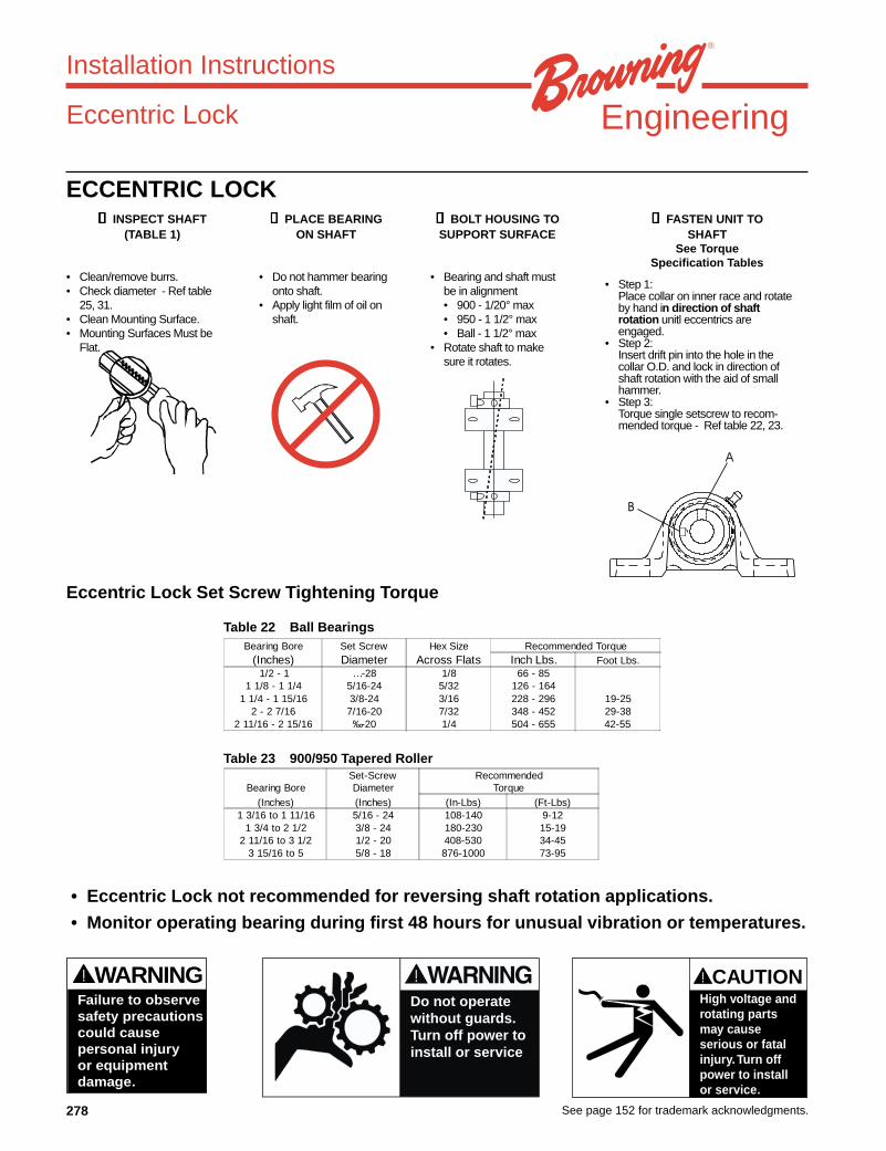
ECCENTRIC LOCK➊➊➊➊➊ INSPECT SHAFT
(TABLE 1)
• Clean/remove burrs.• Check diameter - Ref table
25, 31.• Clean Mounting Surface.• Mounting Surfaces Must be
Flat.
➋➋➋➋➋ PLACE BEARINGON SHAFT
• Do not hammer bearingonto shaft.
• Apply light film of oil onshaft.
➍➍➍➍➍ FASTEN UNIT TOSHAFT
See TorqueSpecification Tables
➌➌➌➌➌ BOLT HOUSING TOSUPPORT SURFACE
• Bearing and shaft mustbe in alignment• 900 - 1/20° max• 950 - 1 1/2° max• Ball - 1 1/2° max
• Rotate shaft to makesure it rotates.
• Step 1:Place collar on inner race and rotateby hand in direction of shaftrotation unitl eccentrics areengaged.
• Step 2:Insert drift pin into the hole in thecollar O.D. and lock in direction ofshaft rotation with the aid of smallhammer.
• Step 3:Torque single setscrew to recom-mended torque - Ref table 22, 23.
Eccentric Lock Set Screw Tightening Torque
Bearing Bore Set Screw Hex Size Recommended Torque(Inches) Diameter Across Flats Inch Lbs. Foot Lbs.
1/2 - 1 …-28 1/8 66 - 851 1/8 - 1 1/4 5/16-24 5/32 126 - 164
1 1/4 - 1 15/16 3/8-24 3/16 228 - 296 19-252 - 2 7/16 7/16-20 7/32 348 - 452 29-38
2 11/16 - 2 15/16 ‰-20 1/4 504 - 655 42-55
Table 22 Ball Bearings
Table 23 900/950 Tapered Roller
Bearing BoreSet-ScrewDiameter
RecommendedTorque
(Inches) (Inches) (In-Lbs) (Ft-Lbs)1 3/16 to 1 11/16 5/16 - 24 108-140 9-12
1 3/4 to 2 1/2 3/8 - 24 180-230 15-192 11/16 to 3 1/2 1/2 - 20 408-530 34-45
3 15/16 to 5 5/8 - 18 876-1000 73-95
• Eccentric Lock not recommended for reversing shaft rotation applications.
• Monitor operating bearing during first 48 hours for unusual vibration or temperatures.
A
B
CAUTION!
High voltage androtating partsmay causeserious or fatalinjury.Turn offpower to installor service.
WARNING!
Failure to observesafety precautionscould causepersonal injuryor equipmentdamage.
Do not operatewithout guards.Turn off power toinstall or service

279See page 152 for trademark acknowledgments.
Engineering
Installation Instructions
Table 24 Ball Bearings
Table 26 920/970 Tapered Roller Bearings
Table 30 900/950 Tapered Roller Bearings
Table 34 1000/1100 Spherical Roller Bearings
Table 25
Table 27
Table 28 Table 29
Table 31
Table 32 Table 33
Table 35
Bore Tolerances For Ball Bearings
Shaft Size(Inches)
Tolerances(Inches)
1/2 to 1 15/16 +.0006/-.0000
2 to 3 3/16 +.0006/-.0000
3 1/4 to 5 +.0007/-.0000
Bore TolearncesShaftSize
(Inches)
BoreTolerance(Inches)
1 3/16 to 3 +.001 / -.0003 3/16 to 5 +.002 / -.000
HOUSING CAP BOLT TORQUES970 SERIES PILLOW BLOCKS
SHAFTSIZE
HOUSING CAP BOLTTORQUES
(Inches) (Ft-Lbs) (In-Lbs)1 3/8, 1 7/16,1 1/2, 1 11/16,
1 3/4, 1 15/16, 22 3/16
2 1/4, 2 7/16, 2 1/22 11/16, 2 15/16, 3
3 3/16, 3 7/16, 3 1/23 15/16, 4
4 7/16, 4 1/24 15/16, 5
30-3540-4550-5570-7570-8090-100170-190265-295120-135195-220
360-400465-515615-680815-900860-950
1100-12152040-22503190-35251470-16202360-2610
Bore TolearncesShaftSize
(Inches)
BoreTolerance(Inches)
1 to 3 1/2 +.001 / -.0003 15/16 to 5 +.002 / -.000
HOUSING CAP BOLT TORQUES950 SERIES PILLOW BLOCKS
SHAFTSIZE
HOUSING CAP BOLTTORQUES
(Inches) (Ft-Lbs) (In-Lbs)1 7/16, 1 1/2
1 5/8, 1 11/16, 1 3/41 7/8, 1 15/16, 2, 2 1/8
2 3/162 1/4, 2 7/16, 2 1/2
2 11/16, 2 3/4, 2 15/163,3 3/16
3 7/16, 3 1/23 15/16, 4
4 7/16, 4 1/24 15/16, 5
30-3540-4550-5570-7570-8090-100140-150170-190265-295120-135195-220
360-400465-515615-680815-900860-950
1100-12151680-18002040-22503190-35251470-16202360-2610
Bore TolerancesNominal Shaft
SizeShaft
Tolerances(Inches) (Inches)
1 1/8 +.0005 / +01 3/16 to 1 15/16 +.0006 / +0
2 to 3 +.0007 / +03 3/16 to 4 15/16 +.0009 / +0
Recommended Shaft Tolerances
Shaft Size(Inches)
Tolerances(Inches)
1/2 to 1 15/16 +.0000/-.0005
2 to 3 3/16 +.0000/-.0010
3 1/4 to 5 +.0000/-.0015
RECOMMENDED SHAFT TOLERANCESNominal
Shaft Size(Inches)
ShaftTolerances
(Inches)1 3/16 to 1 15/16 +.0000 / -.0005
2 to 3 15/16 +.0000 / -.00104 to 5 +.0000 / -.0015
RECOMMENDED SHAFT TOLERANCESNominal
Shaft Size(Inches)
ShaftTolerances
(Inches)1 to 1 15/16 +.0000 / -.00052 to 3 15/16 +.0000 / -.0010
4 to 5 +.0000 / -.0015
HOUSING CAP BOLT TORQUES970 SERIES FLANGED HOUSINGS
SHAFTSIZE
HOUSING CAP BOLTTORQUES
(Inches) (Ft-Lbs) (In-Lbs)1 3/8, 1 7/16,1 1/2, 1 11/16,
1 3/4, 1 15/16, 22 3/16
2 1/4, 2 7/16, 2 1/22 11/16, 2 15/16, 3
3 3/16, 3 7/16, 3 1/23 15/16, 4
4 7/16, 4 1/24 15/16, 5
30-3540-4550-5565-7570-8090-100170-190265-295325-360505-560
365-405465-515615-680810-895855-945
1095-12102040-22553190-35303910-43206065-6705
HOUSING CAP BOLT TORQUES950 SERIES FLANGED HOUSINGS
SHAFTSIZE
HOUSING CAP BOLTTORQUES
(Inches) (Ft-Lbs) (In-Lbs)1 7/16, 1 1/2
1 5/8, 1 11/16, 1 3/41 7/8, 1 15/16, 2, 2 1/8
2 3/162 1/4, 2 7/16, 2 1/2
2 11/16, 2 3/4, 2 15/163,3 3/16
3 7/16, 3 1/23 15/16, 4
4 7/16, 4 1/24 15/16, 5
30-3540-4550-5565-7570-8090-100140-150170-190265-295325-360505-560
365-405465-515615-680810-895855-945
1095-12101655-18252040-22553190-35303910-43206065-6705
Recommended Shaft TolerancesNominal Shaft
SizeShaft
Tolerances(Inches) (Inches)
1 1/8 to 1 15/16 +.0000 / -.00052 to 3 15/16 +.0000 / -.00104 - 4 15/16 +.0000 / -.0015

280 See page 152 for trademark acknowledgments.
Engineering
Installation
22200/22500
Mounting the Bearing and Seal Assemblies in the Housing
• Remove the nuts and lockwashers from the housing cap bolts.• Lift off the cap and remove the stabilizing ring. Do not mix housing caps and bases.
They are machined as a matched set and mixing the cap and bases could result in premature failure.• Install the outward seal rings on the shaft.• Clean the housing using an OSHA approved solvent.• Lift the shaft assembly and place the bearings in the housings, being sure that the seal rings mate with the
grooves in the housing.• Install a stabilizing ring in one bearing housing only, making it non-expansion. Leave out the stabilizing ring for the
other bearing, and then center the other bearing in the other housing so that it is free to move in both directions.• Check the rotation of the shaft. The shaft should rotate freely. Any roughness or binding would indicate an error in
assembly and/or dirt in the bearings and should be corrected before operating the bearings.• Secure the pillow block to the mounting surface by tightening the base bolts. Torque the base bolts to the values
recommended by the base bolt supplier.• Place the corresponding housing caps into position. Tighten the nuts on the cap bolts to the specified values,
using the washers included.• Rotate the shaft again. The shaft should rotate freely.
The load rating for the 22500 series roller bearing units found in the Browning catalog assumethat the bearing unit is base loaded. For any application where there is load carried throughthe cap of the housing, EPT Mounted Bearing Technical Support (see page 256) should becontacted.
CAUTION
Table 36 Table 38
Table 37 Table 39
Recommended Shaft Tolerance
Nominal Shaft Size(Inches)
Shaft Tolerance(Inches)
2 7/16 to 2 1/2 +.000/-.003
2 9/16 to 4 +.000/-.004
4 1/16 to 6 +.000/-.005
6 1/16 to 8 +.000/-.006
Recommended Shaft Tolerance
Shaft Dia.(Inches)
’C’ dim.(Inches)
’R’ dim.(Inches)
Preferred’L’ @ 15(Inches)
Preferred’L’ @ 30(Inches)
2 7/16 to 3 15/16 .093 .188 .313 .156
4 3/16 to 6 15/16 .125 .250 .438 .218
7 3/16 to 7 15/16 .188 .375 .702 .323
Recommended Reduction In InternalClearance
(Feeler Gage Method)
HousingSeries
Reduction in DiametricalClearance
Min.(Inches)
Max.(Inches)
515 .0018 .0022
516 .0018 .0022
517 .0018 .0022
518 .0018 .0022
520 .0020 .0025
522 .0020 .0025
524 .0020 .0025
526 .0026 .0032
528 .0026 .0032
530 .0026 .0032
532 .0032 .0040
534 .0032 .0040
536 .0032 .0040
538 .0032 .0040
540 .0032 .0040
544 .0040 .0050
Recommended Cap Bolt Torque
HousingSeries
Recommended Cap BoltTorque (Ft-Lbs)
Min. Max.
515 43 48
516 86 95
517 86 95
518 86 95
520 86 95
522 153 169
524 153 169
526 153 169
528 153 169
530 246 272
532 222 245
534 222 245
536 222 245
538 314 347
540 443 490
544 443 490

281See page 152 for trademark acknowledgments.
Engineering
Inner Seal Mounting
• Clean the shaft free of burrs. Check that shaft diameter is within specifications.For Standard Labyrinth Seal: Slide the seal on shaft.For Taconite Seal Arrangement: Coat the shaft with oil. Make sure that the end of the shaft has the properchamfer, and slide the V-ring seal on the shaft keeping the lip of the seal towards the bearing. Apply greaseto the bore of the Taconite seal assembly. Place the seal in position on the shaft.
22500 Adapter Mounting
• After installing the inner seal, coat the bore and O.D. of the Adapter Sleeve with a light film of oil.Place the adapter sleeve on the shaft at the desired location.
• Measure and record the internal clearance built into the bearing by inserting the feeler gage at the bottom of thebearing between the outer race and a roller. Do not roll over the feeler gage to get a reading, only use a slidingmotion on the gage to get a reading.
• Seat the bearing hand tight on the adapter by pushing it up the taper• Install the locknut, without washer, hand-tight against the bearing.• Mark the location of the nut with respect to the adapter.• Tighten the locknut until the measured internal clearance between the bottom of the bearing’s outer race and
roller is reduced by the amount shown in the table on the following page.• If the measured reduction in internal clearance exceeds that recommended in the table, rotate the outer race to
seat the rollers and remeasure by inserting the feeler gage between the outer race and rollers. If after severaltries, you are convinced that the clearance removed in the assembly process is greater than that recommended,back off the locknut and repeat the procedure.
• If the measured reduction in internal clearance is within the recommended specifications, back off the locknut andthen securely re-install it with the lockwasher in place.
• Bend the lockwasher tab into the slot in the locknut.
Press Fit Mounting
• After installing the inner seal, fit the bearing on to the shaft.For smaller bearings, apply a light film of oil or micronized graphite to the shaft and bore of the bearing.
• Make sure that the bearing is square on the shaft and use either an arbor press or a hammer, inconjunction with a clean pipe pressed against the edge of the inner race, to press the bearing in toplace.
For larger bearings, bring the bearing up to a maximum temperature of 250° F. This may be accomplished byone of the following methods.
• Place the bearing in an oil bath consisting of either clean oil or a 15% emulsion of oil which is soluble.This should last for 30 minutes to an hour.
• Place the bearing in a temperature controlled oven for no longer than 4 hours, and preferably onlylong enough to assist with the size of the bore.
• Use an induction heater long enough to bring the bore of the bearing up to the necessary size. Onceagain, make sure that this does not go on for more than 4 hours total time.(In any case, an open flame should never be used on the bearing.)
• After getting the bearing bore up to size quickly mount the bearing on the shaft and immediatelycontinue to the following steps.
Installation
22200/22500

282 See page 152 for trademark acknowledgments.
Engineering
SPHERICAL OD BEARING INSERT REMOVAL AND REPLACEMENTBALL BEARING UNITSBall bearing spherical OD Insert removal and replacement procedure. Browning inserts are selectively fit into castings,therefore Browning recommends replacing the entire housed unit.
REMOVAL:
❶❶❶❶❶ REMOVE BEARINGFROM SHAFT
• Loosen set screws.• Slide bearing off shaft.• Do not hammer bearing
off of shaft.• Use flat punch to flatten
set screw marks
❷❷❷❷❷ ROTATE BEARING
• Rotate bearing 90° relative tohousing.
• A lever can be used to aid inthe insert removal.
❸❸❸❸❸ REMOVEINSERT
• Push bearing throughload slots.
REPLACEMENT:
➊➊➊➊➊ LOAD INSERT
• Clean and Check Bore forDebris.
• Rotate bearing 90° relative tohousing.
• With locking side pointed down,push bearing into load slots withrivet in the grease fitting side ofhousing (Left Hand Side).
➋➋➋➋➋ ROTATE BEARING
• Rotate bearing back 90°relative to housing.
• Do not hammer bearinginto housing.
➌➌➌➌➌ ALIGN BEARINGWITH HOUSING
• Align insert with housing toassure proper lubrication.
Installation
Ball BearingInserts Spherical O.D.
Monitor operating bearing during first 48 hours for unusual vibration or temperatures.
CAUTION!
High voltage androtating partsmay causeserious or fatalinjury.Turn offpower to installor service.
WARNING!
Failure to observesafety precautionscould causepersonal injuryor equipmentdamage.
Do not operatewithout guards.Turn off power toinstall or service

283See page 152 for trademark acknowledgments.
Engineering
➊➊➊➊➊ REMOVE CAP BOLTS ➋➋➋➋➋ REMOVE TOP HALF OFHOUSING
REPLACEMENT➊➊➊➊➊ LOAD NEW INSERT
• Place cartridge into housing.➋ ➋ ➋ ➋ ➋ REPLACE TOP HOUSING
HALF• Align location pin with location hole.• Be sure the lock pin is not put into
the lubrication hole.
➌➌➌➌➌ REPLACE CAP BOLTS• Tighten down to recommended
torque (Refer to table.)
Tapered Roller BearingsTAPERED ROLLER INSERT REMOVAL AND REPLACEMENT950 / 970 tapered roller insert/cartridge removal and replacement procedures.
REMOVAL
Installation
Tapered Roller BearingInserts
Table 40 Table 41
➌➌➌➌➌ REMOVE BEARING FROMSHAFT
• Loosen Set Screws.• Slide bearing off shaft.• Do not hammer bearing off of shaft.
CAUTION!
High voltage androtating partsmay causeserious or fatalinjury.Turn offpower to installor service.
WARNING!
Failure to observesafety precautionscould causepersonal injuryor equipmentdamage.
Do not operatewithout guards.Turn off power toinstall or service
Housing Cap Bolt Torques950 and 970 Series Pillow Blocks
Shaft Size(Inches)
Housing Cap Bolt Torques
(Ft-Lbs) (In-Lbs)
1 3/8, 1 7/16 30-35 360-400
1 1/2, 1 11/16 40-45 465-515
1 3/4, 1 15/16, 2 50-55 615-680
2 3/16 70-75 815-900
2 1/4, 2 7/16, 2 1/2 70-80 860-950
2 11/16, 2 15/16, 3 90-100 1100-1215
3 3/16, 3 7/16, 3 1/2 170-190 2040-2250
3 15/16, 4 265-295 3190-3525
4 7/16, 4 1/2 120-135 1470-1620
4 15/16, 5 195-220 2360-2610
Housing Cap Bolt Torques950 and 970 Series Flanged Housings
Shaft Size(Inches)
Housing Cap Bolt Torques
(Ft-Lbs) (In-Lbs)
1 3/8, 1 7/16 30-35 365-405
1 1/2, 1 11/16 40-45 465-515
1 3/4, 1 15/16, 2 50-55 615-680
2 3/16 65-75 810-895
2 1/4, 2 7/16, 2 1/2 70-80 855-945
2 11/16, 2 15/16, 3 90-100 1095-1210
3 3/16, 3 7/16, 3 1/2 170-190 2040-2255
3 15/16, 4 265-295 3190-3530
4 7/16, 4 1/2 325-360 3910-4320
4 15/16, 5 505-560 6065-6705

284 See page 152 for trademark acknowledgments.
Engineering
Lubrication
Consult EPT Mounted Bearing Tech Support for current grease specification.
Grease compatibility is critical. Relubricate with a grease that is compatible with grease supplied from the factory.Consult your grease supplier for compatibility.
Frequency of Lubrication
Frequency of lubrication depends upon operating conditions. The following chart gives the frequency of relubricationbased upon continuous operation for various operating conditions and can be used as a guide for determining whenBrowning ball bearings should be relubricated.
Recommended Relubrication Schedule
Table 43 Ball Bearings
Table 44 Ball Bearings
These charts are general recommendations. Experience and testing may be required for specific applications. Forspeeds, temperatures, and conditions not listed in these tables, please contact EPT Mounted Bearing Tech Support(see page 256).
Table 42 Ball Bearing GreaseBall Bearing Lubrication
Ball Bearings
Thickener Lithium Complex
Oil Petroleum
Thickness NLGI 2
Operating Temperature -20 F to 200 FIntermittent to 250 F
Speed Temperature Cleanliness Greasing Interval
100 RPM -20 F to 125 F Clean 4-10 months
500 RPM -20 F to 150 F Clean 1-4 months
1000 RPM -20 F to 200 F Clean 1 week to 1 month
1500 RPM -20 F to 200 F Clean Biweekly
1500 to MaximumCatalog Rating
Up to 150 F Dirty Daily to 1 week
150 F to 200 F Dirty Daily to 1 week
-20 F to 200 F Very Dirty Daily to 1 week
-20 F to 200 F Extreme Conditions Daily to 1 week
Ball Bearings
Shaft Size(Inches)
Grease Charge(Ounces)
1/2 to 3/4 0.03
7/8 to 1 3/16 0.10
1 1/4 to 1 1/2 0.15
1 11/16 to 1 15/16 0.20
2 to 2 7/16 0.30
2 1/2 to 2 15/16 0.50
3 to 3 7/16 0.85
3 1/2 to 4 1.50

285See page 152 for trademark acknowledgments.
Engineering
Consult EPT Mounted Bearing Tech Support for current grease specification.
Grease compatibility is critical. Relubricate with a grease that is compatible with grease supplied from the factory.Consult your grease supplier for compatibility.
Frequency of Lubrication
Table 46 Recommended Relubrication Schedule - Tapered Roller Bearings
Table 47 920/970 TaperedRoller Bearings
These charts are general recommendations. Experience and testing may be required for specific applications. Forspeeds, temperatures, and conditions not listed in these tables, please contact EPT Mounted Bearing Tech Support(see page 256).
900/950 Series Tapered Roller Bearings
900 and 950 Series tapered roller bearings utilize a labyrinth sealdesign which requires frequent relubrication to maintain maximumeffectiveness. Grease should be added to fully purge and fill thegrease cavity.
In dry, contaminated environments, daily relubrication is requiredfor 900 and 950 series bearings. For moist, wet or contaminatedenvironments consider 920 or 970 Series products.*
Table 45 Tapered Roller Bearing Grease
Lubrication
Tapered Roller Bearing Lubrication
Tapered Roller Bearings
Thickener Lithium 12 Hydroxy Stearate
Oil Petroleum
Thickness NLGI 2
Operating Temperature -20 F to 200 FIntermittent to 250 F
EP Additive Yes
Speed Temperature Cleanliness Greasing Interval
100 RPM -20 F to 125 F Clean 1-4 months
500 RPM -20 F to 150 F Clean 1 week to 1 month
1000 RPM -20 F to 210 F Clean 1-2 weeks
1500 to MaximumCatalog Rating
-20 F to 150 F Dirty Daily to 1 week
150 F to 200 F Dirty Daily to 1 week
-20 F to 200 F Very Dirty * Daily to 1 week
-20 F to 200 F Extreme Conditions * Daily to 1 week
Spherical Roller Bearings
Shaft Size(Inches)
Grease Charge(Ounces)
1 3/16 to 1 1/4 0.10
1 3/8 to 1 7/16 0.22
1 1/2 to 1 11/16 0.32
1 3/4 to 2 0.50
2 to 2 3/16 0.55
2 1/4 to 2 1/2 0.65
2 11/16 to 3 0.85
3 3/16 to 3 1/2 1.25
3 15/16 to 4 2.50
4 7/16 to 4 1/2 3.10
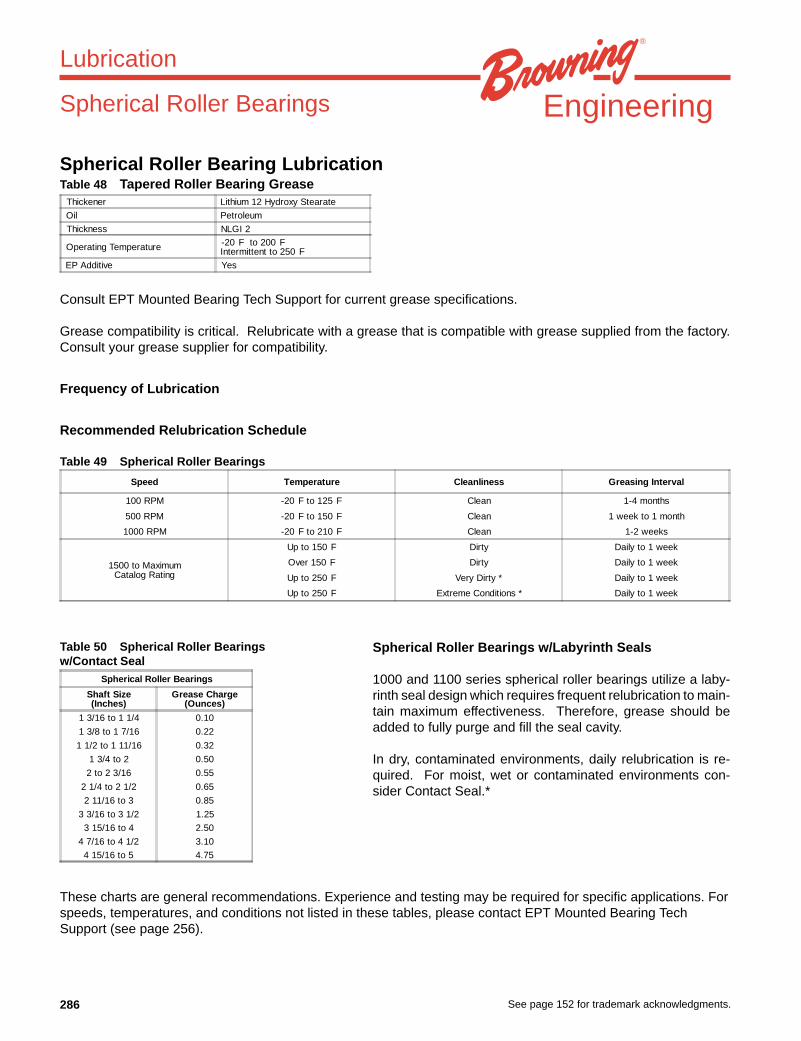
286 See page 152 for trademark acknowledgments.
Engineering
Spherical Roller Bearing Lubrication
Consult EPT Mounted Bearing Tech Support for current grease specifications.
Grease compatibility is critical. Relubricate with a grease that is compatible with grease supplied from the factory.Consult your grease supplier for compatibility.
Frequency of Lubrication
Recommended Relubrication Schedule
Table 49 Spherical Roller Bearings
Table 50 Spherical Roller Bearingsw/Contact Seal
These charts are general recommendations. Experience and testing may be required for specific applications. Forspeeds, temperatures, and conditions not listed in these tables, please contact EPT Mounted Bearing TechSupport (see page 256).
Spherical Roller Bearings w/Labyrinth Seals
1000 and 1100 series spherical roller bearings utilize a laby-rinth seal design which requires frequent relubrication to main-tain maximum effectiveness. Therefore, grease should beadded to fully purge and fill the seal cavity.
In dry, contaminated environments, daily relubrication is re-quired. For moist, wet or contaminated environments con-sider Contact Seal.*
Table 48 Tapered Roller Bearing Grease
Lubrication
Spherical Roller Bearings
Thickener Lithium 12 Hydroxy Stearate
Oil Petroleum
Thickness NLGI 2
Operating Temperature -20 F to 200 FIntermittent to 250 F
EP Additive Yes
Speed Temperature Cleanliness Greasing Interval
100 RPM -20 F to 125 F Clean 1-4 months
500 RPM -20 F to 150 F Clean 1 week to 1 month
1000 RPM -20 F to 210 F Clean 1-2 weeks
1500 to MaximumCatalog Rating
Up to 150 F Dirty Daily to 1 week
Over 150 F Dirty Daily to 1 week
Up to 250 F Very Dirty * Daily to 1 week
Up to 250 F Extreme Conditions * Daily to 1 week
Spherical Roller Bearings
Shaft Size(Inches)
Grease Charge(Ounces)
1 3/16 to 1 1/4 0.10
1 3/8 to 1 7/16 0.22
1 1/2 to 1 11/16 0.32
1 3/4 to 2 0.50
2 to 2 3/16 0.55
2 1/4 to 2 1/2 0.65
2 11/16 to 3 0.85
3 3/16 to 3 1/2 1.25
3 15/16 to 4 2.50
4 7/16 to 4 1/2 3.10
4 15/16 to 5 4.75

287See page 152 for trademark acknowledgments.
Engineering
Fittings and AdaptersTable 51 Ball Bearings Units
Table 52 Tapered Roller and Spherical Roller Bearings Units
Lubrication
BEARING UNITSERIES
SHAFT SIZE
1/2 to 1 1/4S 1 1/4 to 2 15/16 1 1 3/16 to 3 15/16
VF2B - 200 1641B 1610B
VF2B - 300 1641B 1610B
VF2E - 100, 200 1641B 1610B
VF2E - 100M 1641B 1641B
VF2S - 100, 200 1641B 1610B
VF2S - 300 1641B 1610B
VF2S - 100M 1641B 1641B
VF3E - 100M 1641B 1641B
VF3S - 100M 1641B 1641B
VF4B - 200 1641B 1610B
VF4B - 300 1641B 1610B
VF4E - 100, 200 1641B 1610B
VF4S - 100, 200 1641B 1610B
VF4S - 300 1641B 1610B
VFCB - 200 1641B (to 2 3/16) 1610B (2 1/4 up)
VFCB - 300 1641B 1610B
VFCS - 200 1641B (to 2S) 1610B (2 up)
VFCS - 300 1641B (to 2) 1610B (2 3/16 up)
VPE - 100, 200 1641B 1610B
VPE - 100M 1641B 1641B
VPLB - 200 1641B 1610B
VPLE - 100, 200 1641B 1610B
VPLS - 100, 200 1641B 1610B
VPB - 200 1641B 1610B
VPB - 300 1641B 1610B
VPS - 100, 200 1641B 1610B
VPS - 300 1641B 1610B
VPS - 100M 1641B 1641B
VTBE - 200 1641B 1610B
VTBE - 100 1641B 1610B
VTBS - 100, 200 1641B 1610B
VTWE - 100, 200 1911B 1613B
VTWS - 100, 200 1911B 1613B
VTWS - 300 1911B 1613B
900 1610B - All PB, FB, FC 1612B - All TU
920 1610B - All PBE, FBE 1613B - All TUE
950 1610B - All
970 1610B - All
1000 - Thru 4" 1610B - All SPB, SFB 1641B - All SFC
SPB1000F - 4 7/16 - 41 5/16 1627B - 1/4 PTF
1100 1610B - All
22200 PLUGGED
22500 PLUGGED

288 See page 152 for trademark acknowledgments.
Engineering
Browning Fittings/Adapters
1641B Or 51942
1/4-28 NF 1/4-28 Male NF to1/8 NPT Female
1610B Or 43761
1/8 NPT THD 1/8 NPT Male to1/8 NPT Female
1911B 1631B 1612B
1/4-28 NF 1/8 PTF 1/8 PTF
Table 53
Lubrication
Fitting Or Adapter Fitting Or Adapter Fitting Fitting Fitting
1641B 51942 1610B 43761 1911b 1613B 1612B
…-28 NF …-28 Male NF 1/8 NPT THD 1/8 NPT Male …-28 NF 1/8 PTF 1/8 PTF
to 1/8 NPT Fem to 1/8 NPT Fem

289See page 152 for trademark acknowledgments.
Engineering
Browning Ball Bearings - Vibration AnalysisThe following is the procedure to be followed in calculating the fundamental frequencies for Browning ball bearings.
1. If the Browning insert number is known, proceed to step 2. For housed units, identify the bearing insert number bylooking up the unit in the Browning Catalog, then proceed to step 2.
2. Find your Browning insert number in Table 54 below and identify the series.3. Select the vibration geometry information (O, I, B, F) from Table 54 based on bearing series.4. Use this information to calculate the fundamental bearing frequencies by multiplying the factor in Table 55 by the
shaft speed (in RPM).
Outer Ball Pass Freq. (Hz) = O x RPMInner Ball Pass Freq. (Hz) = I x RPMBall Spin Freq. (Hz) = B x RPMFundamental Train Freq. (Hz) = F x RPM
TABLE 54 BROWNING INSERT SERIES
Where X denotes one of: LE, LS, RUBRE, RUBRS, SLE, LRE, LRS, SLS, VB, VE, VER, VS,
Vibration Analysis
Ball Bearings
SERIES VALULINE INSERT
L-10 X-108 X-110 X-208 X-210
2-012 X-112 X-212
2-015 X-114 X-115 X-116 X-214 X-215 X-216
2-13 X-118 X-119 X-120S X-218 X-219 X-220S X-316
2-17 X-120 X-122 X-123 X-220 X-222 X-223 X-319 X-320
2-19 X-124 X-224 X-323
2-111 X-126 X-127 X-128 X-226 X-227 X-228 X-324
2-115 X-130 X-131 X-132S X-230 X-231 X-232S X-327 X-328
2-23 X-132 X-134 X-135 X-232 X-234 X-235 X-331 X-332
2-27 X-236 X-239 X-335 X-336
2-211 X-240 X-243 X-339 X-340
2-215 X-247 X-343
2-33 X-347 X-348
2-38 X-355 X-356
2-43 X-363

290 See page 152 for trademark acknowledgments.
Engineering
TABLE 55 VIBRATION INFORMATION
Browning Ball Bearings - Vibration Analysis
Vibration Analysis
Ball Bearings
SERIESPitch Diameter
(in)dM
Number ofBalls
N
BallDiameter(in)D
Factor For OuterBall Pass
O
Factor For InnerBall Pass
I
Factor For BallSpin
B
Factor For Fund.Train
F
L-10 1.138 9 1/4 0.0585 0.0915 0.0361 0.0065
2-012 1.345 9 9/32 0.0593 0.0907 0.0381 0.0066
2-015 1.544 10 9/32 0.0682 0.0985 0.0442 0.0068
2-13 1.812 9 3/8 0.0595 0.0905 0.0385 0.0066
2-17 2.115 9 7/16 0.0595 0.0905 0.0386 0.0066
2-19 2.362 9 1/2 0.0591 0.0909 0.0376 0.0066
2-111 2.596 10 1/2 0.0673 0.0994 0.0417 0.0067
2-115 2.763 10 1/2 0.0683 0.0984 0.0445 0.0068
2-23 3.051 10 9/16 0.0680 0.0987 0.0437 0.0068
2-27 3.356 10 5/8 0.0678 0.0989 0.0432 0.0068
2-211 3.846 10 11/16 0.0684 0.0982 0.0451 0.0068
2-215 4.045 11 11/16 0.0761 0.1072 0.0476 0.0069
2-33 4.362 11 3/4 0.0759 0.1074 0.0470 0.0069
2-37 4.627 11 25/32 0.0762 0.1071 0.0479 0.0069
2-38 4.922 10 7/8 0.0685 0.0981 0.0454 0.0069
2-43 5.808 10 1-1/16 0.0681 0.0986 0.0440 0.0068

291See page 152 for trademark acknowledgments.
Engineering
The following is the procedure which should be followed in calculating the fundamental frequencies for Browning 900and 950 tapered roller bearings.1. The bore size for each bearing to be analyzed must be known.2. Once the bore size is known the appropriate vibration factors (O,I,B and F) can be chosen from Table 56.3. These factors can then be used to calculate the fundamental bearing frequencies as follows:
Roller Spin Frequency (Hz) = O x RPMInner Race Pass Frequency (Hz) = I x RPMOuter Race Pass Frequency (Hz) = B x RPMFundamental Train Frequency (Hz) = F x RPM
Table 56 Vibration information
Browning 900 & 950 Tapered Roller Bearings - Vibration Analysis
Vibration Analysis
Tapered Roller Bearings
SHAFTSIZE
(INCHES)
FACTOR FORROLLER SPIN
O
FACTOR FORINNER ROLLER PASS
I
FACTOR FOROUTER ROLLER PASS
B
FACTOR FORFUND. TRAIN
F
1 0.1197 0.1794 0.1373 0.0072
1 3/16
1 1/4 0.1136 0.1616 0.1218 0.0072
1 3/8
1 7/160.1195 0.1795 0.1372 0.0072
1 1/2
1 5/8
1 11/16 0.1284 0.1873 0.1460 0.0073
1 3/4
1 7/8
0.1216 0.1792 0.1375 0.00721 15/16
2
2 1/8
2 3/16 0.1345 0.1958 0.1542 0.0073
2 1/4
2 7/16 0.1397 0.2043 0.1623 0.0074
2 1/2
2 11/16
2 3/4 0.1578 0.2202 0.1798 0.0075
2 15/16
30.1535 0.2116 0.1718 0.0075
3 3/16
3 7/160.1706 0.2368 0.1966 0.0076
3 1/2
3 15/160.2258 0.3035 0.2631 0.0077
4
4 7/160.2204 0.2953 0.2547 0.0077
4 1/2
4 15/160.2324 0.3210 0.2790 0.0078
5
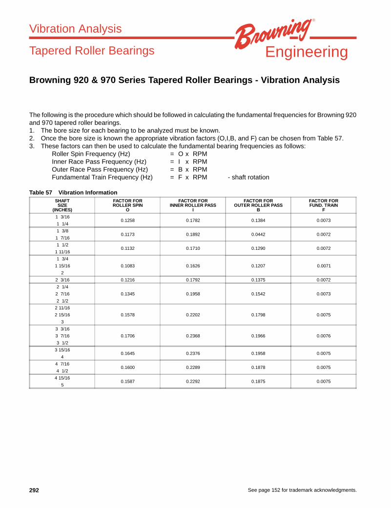
292 See page 152 for trademark acknowledgments.
Engineering
Browning 920 & 970 Series Tapered Roller Bearings - Vibration Analysis
The following is the procedure which should be followed in calculating the fundamental frequencies for Browning 920and 970 tapered roller bearings.1. The bore size for each bearing to be analyzed must be known.2. Once the bore size is known the appropriate vibration factors (O,I,B, and F) can be chosen from Table 57.3. These factors can then be used to calculate the fundamental bearing frequencies as follows:
Roller Spin Frequency (Hz) = O x RPMInner Race Pass Frequency (Hz) = I x RPMOuter Race Pass Frequency (Hz) = B x RPMFundamental Train Frequency (Hz) = F x RPM - shaft rotation
Table 57 Vibration Information
Vibration Analysis
Tapered Roller Bearings
SHAFTSIZE
(INCHES)
FACTOR FORROLLER SPIN
O
FACTOR FORINNER ROLLER PASS
I
FACTOR FOROUTER ROLLER PASS
B
FACTOR FORFUND. TRAIN
F
1 3/160.1258 0.1782 0.1384 0.0073
1 1/4
1 3/80.1173 0.1892 0.0442 0.0072
1 7/16
1 1/20.1132 0.1710 0.1290 0.0072
1 11/16
1 3/4
1 15/16 0.1083 0.1626 0.1207 0.0071
2
2 3/16 0.1216 0.1792 0.1375 0.0072
2 1/4
2 7/16 0.1345 0.1958 0.1542 0.0073
2 1/2
2 11/16
0.1578 0.2202 0.1798 0.00752 15/16
3
3 3/16
3 7/16 0.1706 0.2368 0.1966 0.0076
3 1/2
3 15/160.1645 0.2376 0.1958 0.0075
4
4 7/160.1600 0.2289 0.1878 0.0075
4 1/2
4 15/160.1587 0.2292 0.1875 0.0075
5
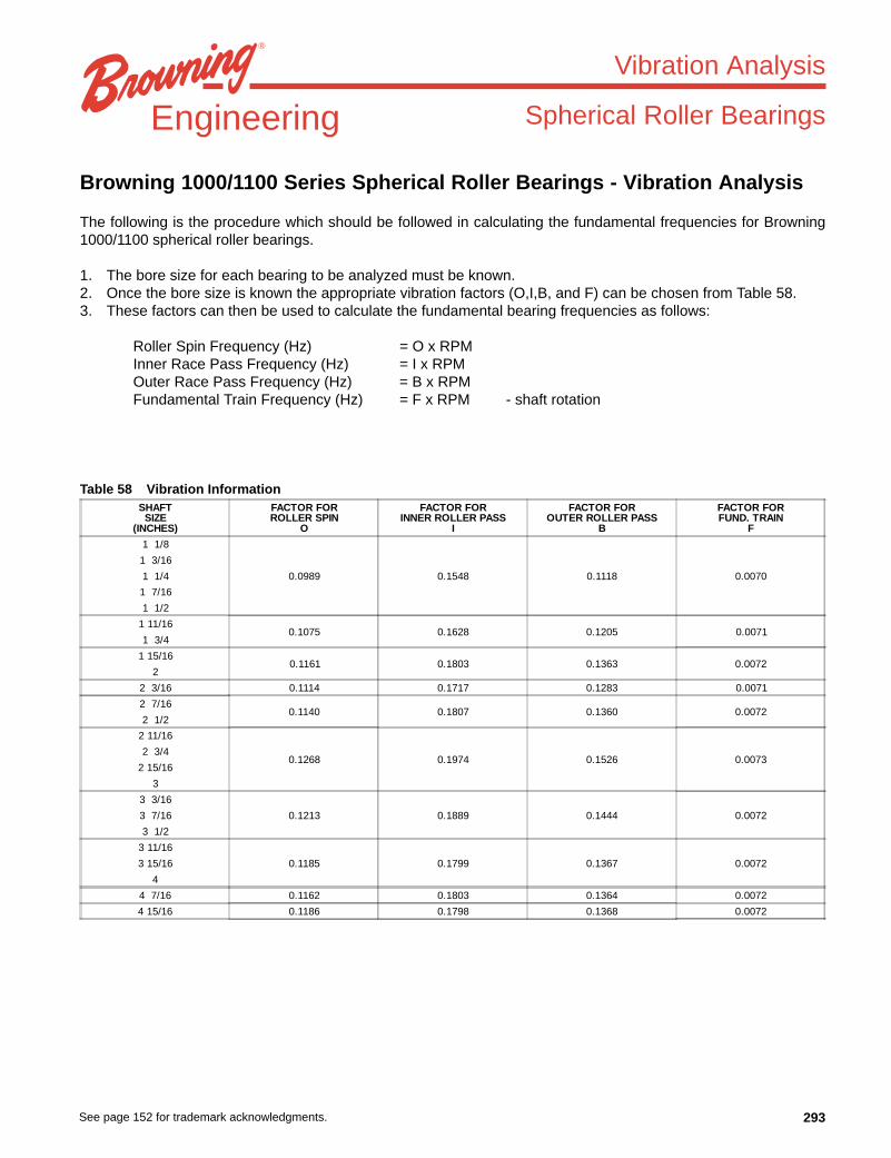
293See page 152 for trademark acknowledgments.
Engineering
Browning 1000/1100 Series Spherical Roller Bearings - Vibration Analysis
The following is the procedure which should be followed in calculating the fundamental frequencies for Browning1000/1100 spherical roller bearings.
1. The bore size for each bearing to be analyzed must be known.2. Once the bore size is known the appropriate vibration factors (O,I,B, and F) can be chosen from Table 58.3. These factors can then be used to calculate the fundamental bearing frequencies as follows:
Roller Spin Frequency (Hz) = O x RPMInner Race Pass Frequency (Hz) = I x RPMOuter Race Pass Frequency (Hz) = B x RPMFundamental Train Frequency (Hz) = F x RPM - shaft rotation
Table 58 Vibration Information
Vibration Analysis
Spherical Roller Bearings
SHAFTSIZE
(INCHES)
FACTOR FORROLLER SPIN
O
FACTOR FORINNER ROLLER PASS
I
FACTOR FOROUTER ROLLER PASS
B
FACTOR FORFUND. TRAIN
F
1 1/8
0.0989 0.1548
1 3/16
1 1/4 0.1118 0.0070
1 7/16
1 1/2
1 11/160.1075 0.1628 0.1205 0.0071
1 3/4
1 15/160.1161 0.1803 0.1363 0.0072
2
2 3/16 0.1114 0.1717 0.1283 0.0071
2 7/160.1140 0.1807 0.1360 0.0072
2 1/2
2 11/16
0.1268 0.1974 0.1526 0.00732 3/4
2 15/16
3
3 3/16
0.00723 7/16 0.1213 0.1889 0.1444
3 1/2
3 11/16
0.00723 15/16 0.1185 0.1799 0.1367
4
4 7/16 0.1162 0.1803 0.1364 0.0072
4 15/16 0.1186 0.1798 0.1368 0.0072

294 See page 152 for trademark acknowledgments.
Engineering
Browning 22500 Series Spherical Roller Bearings - Vibration Analysis
The following is the procedure which should be followed in calculating the fundamental frequencies for Browning22500 series spherical roller bearings.1. The bore size for each bearing to be analyzed must be known.2. Once the bore size is known the appropriate vibration factors (O,I,B and F) can be chosen from Table 59.3. These factors can then be used to calculate the fundamental bearing frequencies as follows:
Roller Spin Frequency (Hz) = O x RPMInner Race Pass Frequency (Hz) = I x RPMOuter Race Pass Frequency (Hz) = B x RPMFundamental Train Frequency (Hz) = F x RPM - shaft rotation
Table 59 Vibration Information
Vibration Analysis
Spherical Roller Bearings
SHAFTSIZE
(INCHES)
FACTOR FORROLLER SPIN
O
FACTOR FORINNER ROLLER PASS
I
FACTOR FOROUTER ROLLER PASS
B
FACTOR FORFUND. TRAIN
F
2 7/16"0.1268 0.1786 0.1381 0.0073
2 1/2"
2 11/16"0.1253 0.1788 0.1378 0.0073
2 3/4"
2 15/16"0.1209 0.1701 0.1299 0.0072
3"
3 3/16" 0.1213 0.17 0.13 0.0072
3 7/16"0.1185 0.1799 0.1366 0.0072
3 1/2"
3 11/16"
0.1162 0.1803 0.1364 0.00723 15/16"
4"
4 3/16" 0.1173 0.1801 0.1366 0.0072
4 7/16"0.1186 0.1798 0.1368 0.0072
4 1/2"
4 15/16"0.1189 0.1798 0.1369 0.0072
5"
5 3/16" 0.1154 0.1804 0.1362 0.0072
5 7/16"0.1157 0.1804 0.1363 0.0072
5 1/2"
5 15/16"0.1155 0.1804 0.1363 0.0072
6"
6 7/16"0.1194 0.1892 0.1442 0.0072
6 1/2"
6 15/16"0.1180 0.1800 0.1367 0.0072
7"
7 3/16" 0.1155 0.1804 0.1363 0.0072
7 1/2"
0.1155 0.1803 0.1364 0.00727 15/16"
8"

295See page 152 for trademark acknowledgments.
Index
BALL BEARINGSSET SCREW ....................................... 4AIR HANDLING ................................. 48BOA™ ................................................ 50ECCENTRIC ......................................66
TAPERED ROLLER BEARINGS900 .....................................................99E920 ..................................................99950 ................................................... 112970 ................................................... 112
SPHERICAL ROLLER BEARINGS1000 ................................................. 1241100 ................................................. 12422500 ...............................................13622200 ...............................................136
INTERCHANGESHEAD TO HEAD OVERVIEWS ....... 152BALL AND ROLLERALPHA-NUMERIC ...........................162
ENGINEERING ....................................256
PRODUCTS12SF ..................................................1312TF ..................................................1318SF ..................................................1318TF ..................................................131SF .................................................... 1322200CKW33C3 ..............................14322200CW33C3 ................................1453SF .................................................... 136SF .................................................... 136TF .................................................... 139SF .................................................... 139TF .................................................... 13ANW ................................................146C950 ................................................ 116C970 .............................................. 1120EC .................................................... 147FB900 .............................................. 101FB950E ............................................ 115FB950NE ......................................... 115FB970E ............................................ 119FB970NE ......................................... 119FBE920 ............................................107FC900 .............................................. 102LE-100 ...............................................93LRS-100 ............................................. 43LS-100 ...............................................44PB900 .............................................. 100PB950E ............................................ 114PB950FE ......................................... 114PB950FNE ....................................... 114PB950NE ......................................... 114PB970E ............................................ 118PB970FE ......................................... 118PB970FNE ....................................... 118PB970NE ......................................... 118PBE920 ............................................106PBE920F .........................................106RUBRE-100 ....................................... 91RUBRS-100 ....................................... 41SFB1000NE-3 .................................127SFB1000NEC-3 ............................... 127SFB1000NEC .................................. 126
SFB1100E ........................................133SFB1100EC .....................................133SFB1100NE .....................................133SFB1100NEC ..................................133SFC1000E .......................................130SFC1000EC ....................................130SFC1000NE ....................................130SFC1000NEC ..................................130SFC1100E .......................................134SFC1100EC .....................................134SFC1100NE .....................................134SFC1100NEC ..................................134SLE-100 ............................................. 92SLS-100 ............................................. 42SNW ................................................144SPB1000E .......................................124SPB1000EC ....................................124SPB1000FE .....................................125SPB1000FEC ..................................125SPB1000FNE ..................................125SPB1000FNEC ................................125SPB1000NE ....................................124SPB1000NEC ..................................124SPB1100E .......................................132SPB1100EC .....................................132SPB1100NE .....................................132SPB1100NEC ..................................132SPBF22200 .....................................141SPBF22500 .....................................139SPBF22500XTC ..............................148SPBF22500XTE ..............................148SPBFS22200 ...................................142SPBT22200 .....................................141SPBT22500 .....................................138SPBT22500XEC ..............................147SPBT22500XTC ..............................148SPBT22500XTE ..............................148SPBTS22200 ...................................142SPBTS22500 ...................................140SSF2E-100 ........................................ 87SSF2S-100 ........................................ 37SSF3E-100 ........................................ 88SSF3S-100 ........................................ 38SSF3TE-100 ...................................... 90SSF3TS-100 ...................................... 40SSF4E-100 ........................................ 89SSF4S-100 ........................................ 39SSPE-100 .......................................... 86SSPS-100 .......................................... 36SSRPE-100 ....................................... 85SSRPS-100 ....................................... 35STU1000NE ....................................128STU1000NEC ..................................128T1000 ...............................................109T1000 ...............................................129T2000-2 ...........................................149T2000-4 ...........................................150T900 .................................................105TU900 ..............................................104TUE920 ............................................108VB-200 ............................................... 58VB-300 ............................................... 64VE-100 ............................................... 94VE-200 ............................................... 74VER-200 ............................................ 14
VF2B-200 ........................................... 54VF2B-300 ........................................... 61VF2E-100 ........................................... 78VF2E-100M........................................ 82VF2E-200 ........................................... 70VF2S-100 ........................................... 28VF2S-100M........................................ 32VF2S-200 ............................................. 8VF2S-200 AH ...................................... 8VF2S-200 NK ...................................... 8VF2S-300 ........................................... 19VF2S-300 AH .................................... 19VF3E-100M........................................ 84VF3S-100M........................................ 34VF4B-200 ........................................... 55VF4B-300 ........................................... 62VF4E-100 ........................................... 79VF4E-200 ........................................... 71VF4S-100 ........................................... 29VF4S-200 ............................................. 9VF4S-200 ........................................... 20VF4S-200 AH ...................................... 9VF4S-200 AH .................................... 20VF4S-200 NK ...................................... 9VFCB-200 .......................................... 57VFCB-300 .......................................... 63VFCS-200 .......................................... 10VFCS-300 .......................................... 21VPB-200 ............................................52VPB-200 AH ......................................52VPB-300 ............................................60VPB-300 AH ......................................60VPE-100 ............................................76VPE-100M .........................................83VPE-200 ............................................68VPE-200 NK ......................................68VPLB-200 .......................................... 53VPLE-100 .......................................... 77VPLE-200 .......................................... 69VPLE-200 AH .................................... 69VPLE-200 NK .................................... 69VPLS-100 .......................................... 27VPLS-200 ............................................ 7VPLS-200 AH ...................................... 7VPLS-200 NK ...................................... 7VPS-100 ............................................26VPS-100M .........................................33VPS-200 .............................................. 6VPS-200 AH ........................................ 6VPS-200 NK ........................................ 6VPS-300 ............................................18VPS-300 AH ......................................18VS-100 ...............................................45VS-200 ...............................................16VS-300 ...............................................24VTBB-200 .......................................... 56VTBE-100 .......................................... 80VTBS-200 .......................................... 11VTBS-200 NK .................................... 11VTWE-100 .........................................81VTWE-200 .........................................72VTWS-100 .........................................30VTWS-200 .........................................12VTWS-200 NK ...................................12VTWS-300 .........................................22
296
1. PRICES: Unless otherwise specified in writing by Seller, Seller’s price for the goodsshall remain in effect for thirty (30) days after the date of Seller’s quotation or acknowl-edgment of Buyer’s order for the Goods, whichever occurs first, provided an uncondi-tional, complete authorization for the immediate shipment of the Goods is received andaccepted by Seller within such time period. If such authorization is not received bySeller within such thirty (30) day period, Seller shall have the right to change the pricefor the Good to Seller’s price for the Goods at the time of shipment.2. TAXES: Any tax or governmental charge or increase in same hereafter becomingeffective increasing the cost to Seller of producing, selling or delivering the Goods or ofprocuring material used therein, and any tax now in effect or increase in same payableby the Seller because of the manufacture, sale or delivery of the Goods, may at Seller’soption, be added to the price.3. TERMS OF PAYMENT: Subject to the approval of Seller’s Credit Department, termsare net thirty (30) days from date of Seller’s invoice in U.S. currency. If any paymentowed to Seller is not paid when due, it shall bear interest, at a rate to be determined bySeller, which shall not exceed the maximum rate permitted by law, from the date onwhich it is due until it is paid. Seller shall have the right, among other remedies, eitherto terminate the Agreement or to suspend further performance under this and/or otheragreements with Buyer in the event Buyer fails to make any payment when due. Buyershall be liable for all expenses, including attorneys’ fees, relating to the collection ofpast due amounts.4. SHIPMENT AND DELIVERY: Shipments are made F.O.B. Seller’s shipping point.Any claims for shortages or damages suffered in transit shall be submitted by theBuyer directly to the carrier. While Seller will use all reasonable commercial efforts tomaintain the delivery date acknowledged or quoted by Seller, all shipping dates areapproximate. Seller reserves the right to make partial shipments and to segregate“specials” and made-to-order Goods from normal stock Goods. Seller shall not bebound to tender delivery of any Goods for which Buyer has not provided shippinginstructions.5. QUANTITY: Buyer agrees to accept overruns of up to ten percent (10%) of the orderon “made-to-order” Goods, including parts. Any such additional items shall be priced atthe price per item charged for the specific quantity ordered.6. LIMITED WARRANTY: Subject to the limitations of Section 7, Seller warrants thatthe Goods will be free from defects in material and workmanship under normal use,service and maintenance for a period of one year (unless otherwise specified by Sellerin writing) from the date of shipment of the Goods by Seller. THIS IS THE SOLE ANDEXCLUSIVE WARRANTY GIVEN BY SELLER WITH RESPECT TO THE GOODSAND IS IN LIEU OF AND EXCLUDES ALL OTHER WARRANTIES, EXPRESS ORIMPLIED, ARISING BY OPERATION OF LAW OR OTHERWISE, INCLUDING WITH-OUT LIMITATION, MERCHANTABILITY OR FITNESS FOR A PARTICULAR PUR-POSE WHETHER OR NOT THE PURPOSE OR USE HAS BEEN DISCLOSED TOSELLER IN SPECIFICATIONS, DRAWINGS OR OTHERWISE, AND WHETHER ORNOT SELLER’S PRODUCTS ARE SPECIFICALLY DESIGNED AND/OR MANUFAC-TURED BY SELLER FOR BUYER’S USE OR PURPOSE.This warranty does not extend to any losses or damages due to misuse, accident,abuse, neglect, normal wear and tear, unauthorized modification or alteration, use be-yond rated capacity, or improper installation, maintenance or application. To the extentthat Buyer or its agents has supplied specifications, information, representation of op-erating conditions or other data to Seller in the selection or design of the Goods andthe preparation of Seller’s quotation, and in the event that actual operating conditionsor other conditions differ from those represented by Buyer, any warranties or otherprovisions contained herein which are affected by such conditions shall be null andvoid. If within thirty (30) days after Buyer’s discovery of any warranty defects within thewarranty period, Buyer notifies Seller thereof in writing, Seller shall, at its option, repairor replace F.O.B. point of manufacture, or refund the purchase price for, that portion ofthe goods found by Seller to be defective. Failure by Buyer to give such written noticewithin the applicable time period shall be deemed an absolute and unconditional waiverof Buyer’s claim for such defects. Goods repaired or replaced during the warrantyperiod shall be covered by the foregoing warranty for the remainder of the originalwarranty period or ninety (90) days, whichever is longer. Buyer assumes all other re-sponsibility for any loss, damage, or injury to persons or property arising out of, con-nected with, or resulting from the use of Goods, either alone or in combination withother products/components.SECTIONS 6 AND 7 APPLY TO ANY ENTITY OR PERSON WHO MAY BUY, AC-QUIRE OR USE SELLER’S GOODS, INCLUDING ANY ENTITY OR PERSON WHOBUYS THE GOODS FROM SELLER’S DISTRIBUTOR AND SUCH ENTITY OR PER-SON SHALL BE BOUND BY THE LIMITATIONS THEREIN.7. LIMITATION OF REMEDY AND LIABILITY: THE SOLE AND EXCLUSIVE REM-EDY FOR BREACH OF ANY WARRANTY HEREUNDER (OTHER THAN THE WAR-RANTY PROVIDED UNDER SECTION 13) SHALL BE LIMITED TO REPAIR, RE-PLACEMENT OR REFUND OF THE PURCHASE PRICE UNDER SECTION 6.SELLER SHALL NOT BE LIABLE FOR DAMAGES CAUSED BY DELAY IN PER-FORMANCE AND IN NO EVENT, REGARDLESS OF THE FORM OF THE CLAIMOR CAUSE OF ACTION (WHETHER BASED IN CONTRACT, INFRINGEMENT, NEG-LIGENCE, STRICT LIABILITY, OTHER TORT OR OTHERWISE), SHALL SELLER’SLIABILITY TO BUYER AND/OR ITS CUSTOMERS EXCEED THE PRICE TO BUYEROF THE SPECIFIC GOODS PROVIDED BY SELLER GIVING RISE TO THE CLAIMOR CAUSE OF ACTION. BUYER AGREES THAT IN NO EVENT SHALL SELLER’SLIABILITY TO BUYER AND/OR ITS CUSTOMERS EXTEND TO INCLUDE INCI-DENTAL, CONSEQUENTIAL OR PUNITIVE DAMAGES. THE TERM “CONSEQUEN-TIAL DAMAGES” SHALL INCLUDE, BUT NOT BE LIMITED TO, LOSS OF
ANTICIPATED PROFITS, LOSS OF USE, LOSS OF REVENUE, COST OF CAPITALAND DAMAGE OR LOSS OF OTHER PROPERTY OR EQUIPMENT.It is expressly understood that any technical advice furnished by Seller with respect tothe use of the Goods is given without charge, and Seller assumes no obligation orliability for the advice given, or results obtained, all such advice being given and ac-cepted at Buyer’s risk.GOODS AND/OR SERVICES SOLD HEREUNDER ARE NOT FOR USE IN ANYNUCLEAR AND RELATED APPLICATIONS. Buyer accepts goods and/or serviceswith the foregoing understanding, agrees to communicate the same in writing to anysubsequent purchaser or users and to defend, indemnify and hold harmless Seller fromany claims, losses, suits, judgments and damages, including incidental and consequen-tial damages, arising from such use, whether the cause of action be based in tort,contract or otherwise, including allegations that the Seller's liability is based onnegligence or strict liability.8. EXCUSE OF PERFORMANCE: Seller shall not be liable for delays in performanceor for non-performance due to acts of God, acts of Buyer, war, riot, fire, flood, othersevere weather, sabotage, or epidemics; strikes or labor disturbances; governmentalrequests, restrictions, laws, regulations, orders or actions; unavailability of or delays intransportation; default of suppliers; or unforeseen circumstances or any events or causesbeyond Seller’s reasonable control. Deliveries may be suspended for an appropriateperiod of time as a result of the foregoing. If Seller determines that its ability to supplythe total demand for the Goods, or to obtain material used directly or indirectly in themanufacture of the Goods, is hindered, limited or made impracticable due to causesaddressed in this Section 8, Seller may allocate its available supply of the Goods orsuch material (without obligation to acquire other supplies of any such Goods or mate-rial) among itself and its purchasers on such basis as Seller determines to be equitablewithout liability for any failure of performance which may result therefrom. Deliveriessuspended or not made by reason of this section may be canceled by Seller uponnotice to Buyer without liability, but the balance of the agreement shall otherwise re-main unaffected.9. CANCELLATION: The Buyer may cancel orders only upon written notice and uponpayment to Seller of cancellation charges which include, among other things, all costsand expenses incurred and commitments made by the Seller and a reasonable profitthereon.10. CHANGES: Buyer may request changes or additions to the Goods consistent withSeller’s specifications and criteria. In the event such changes or additions are ac-cepted by Seller, Seller may revise the price and delivery schedule. Seller reserves theright to change designs and specifications for the Goods without prior notice to Buyer,except with respect to Goods being made-to-order for Buyer.
11. TOOLING: Tool, die, and pattern charges, if any, are in addition to the price of theGoods and are due and payable upon completion of the tooling. All such tools, diesand patterns shall be and remain the property of Seller. Charges for tools, dies, andpatterns do not convey to Buyer, title, ownership interests in, or rights to possession orremoval, nor prevent their use by Seller for other purchasers, except as otherwiseexpressly provided by Seller and Buyer in writing with reference to this provision.
12. ASSIGNMENT: Buyer shall not assign its rights or delegate its duties hereunder orany interest therein or any rights hereunder without the prior written consent of theSeller, and any such assignment, without such consent, shall be void.13. PATENTS AND COPYRIGHTS: Subject to Section 7, Seller warrants that the Goodssold, except as are made specifically for Buyer according to Buyer’s specifications, donot infringe any valid U.S. patent or copyright in existence as of the date of delivery.This warranty is given upon the condition that Buyer promptly notify Seller of any claimor suit involving Buyer in which such infringement is alleged, and, that Buyer cooperatefully with Seller and permit Seller to control completely the defense or compromise ofany such allegation of infringement. Seller’s warranty as to use only applies to infringe-ments arising solely out of the inherent operation (i) of such Goods, or (ii) of any com-bination of Goods in a system designed by Seller. In the event such Goods, singularlyor in combination, are held to infringe a U.S. patent or copyright in such suit, and theuse of such Goods is enjoined, or in the case of a compromise by Seller, Seller shallhave the right, at its option and expense, to procure for Buyer the right to continueusing such Goods, or replace them with non-infringing Goods; or modify same to be-come non-infringing; or grant Buyer a credit for the depreciated value of such Goodsand accept return of them.14. MISCELLANEOUS: These terms and conditions set forth the entire understandingand agreement between Seller and Buyer, and supersede all other communications,negotiations and prior oral or written statements regarding the subject matter of theseterms and conditions. No change, modification, rescission, discharge, abandonment,or waiver of these terms and conditions of Sale shall be binding upon the Seller unlessmade in writing and signed on its behalf by an officer of the Seller. No conditions,usage or trade, course of dealing or performance, understanding or agreement pur-porting to modify, vary, explain, or supplement these Terms and Conditions shall bebinding unless hereafter made in writing and signed by the party to be bound, and nomodification shall be affected by the acceptance of purchase orders or shipping in-struction forms containing terms at variance with or in addition to those set forth herein.No waiver by Seller with respect to any breach or default or any right or remedy and nocourse of dealing, shall be deemed to constitute a continuing waiver of any other breachor default or of any other right or remedy, unless such waiver be expressed in writingand signed by the party to be bound. Seller is not responsible for typographical orclerical errors made in any quotation, orders or publications. All such errors are subjectto correction. The validity, performance, and all other matters relating to the interpreta-tion and effect of this contract shall be governed by the law of the state of New York.
All sales are made on our STANDARD TERMS AND CONDITIONS OF SALE in effect at the time a customer’s order is accepted. The current Terms and Conditions are set forth below:
STANDARD TERMS AND CONDITIONS OF SALE (March 19, 1999)
These Terms and Conditions, the attendant quotation or acknowledgment and all documents incorporated by specific reference therein, will be the complete and exclusive statementof the terms of the agreement governing the sale of goods (“Goods”) by Emerson Power Transmission Corporation and its divisions and subsidiaries (“Seller”) to Customer(“Buyer”). Buyer’s acceptance of the Goods will manifest Buyer’s assent to these Terms and Conditions. If these Terms and Conditions differ in any way from the terms and conditionsof Buyer’s order, or other documentation, this document will be construed as a counteroffer and will not be deemed an acceptance of Buyer’s terms and conditions which conflictherewith.