Embed Size (px)
Citation preview

7/18/2019 Brother Mfc 9125cn 9325cw en 5694 Mfp Sm
http://slidepdf.com/reader/full/brother-mfc-9125cn-9325cw-en-5694-mfp-sm 1/597
Confidential
July 2009
SM-FAX113
8CE203
(4)
Color FAX/MFC
SERVICE MANUAL
MODEL: DCP-9010CN/MFC-9010CN
MFC-9120CN/MFC-9125CNMFC-9320CW/MFC-9325CW
Read this manual thoroughly before maintenance work.
Keep this manual in a convenient place for quick and easy reference at all times.

7/18/2019 Brother Mfc 9125cn 9325cw en 5694 Mfp Sm
http://slidepdf.com/reader/full/brother-mfc-9125cn-9325cw-en-5694-mfp-sm 2/597
Confidential
TRADEMARKS
The Brother logo is a registered trademark of Brother Industries, Ltd.
Apple and Macintosh are trademarks of Apple Inc., registered in the United States and other countries.
PCL is either a trademark or a registered trademark of Hewlett-Packard Company in the United States
and other countries.
Windows Vista is either a registered trademark or a trademark of Microsoft Corporation in the United
States and/or other countries.
Microsoft, Windows, Windows Server and Internet Explorer are registered trademarks of Microsoft
Corporation in the United States and/or other countries.
Linux is a registered trademark of Linus Torvalds in the United States and other countries.
PostScript and PostScript3 are either registered trademarks or trademarks of Adobe Systems
Incorporated in the United States and/or other countries.
ENERGY STAR is a U.S. registered mark.
Citrix and MetaFrame are registered trademarks of Citrix Systems, Inc. in the United States.
Intel, Intel Xeon and Pentium are trademarks or registered trademarks of Intel Corporation.
AMD, AMD Athlon, AMD Opteron and combinations thereof, are trademarks of Advanced Micro
Devices, Inc.
PictBridge is a trademark.
Each company whose software title is mentioned in this manual has a Software License Agreement
specific to its proprietary programs.
All other trademarks are the property of their respective owners.
The function comparative table for models as described in this Service manual are shown blow.
© Copyright Brother 2009
All rights reserved.
No part of this publication may be reproduced in any form or by
any means without permission in writing from the publisher.
All other product and company names mentioned in this manual
are trademarks or registered trademarks of their respective
holders.
Specifications are subject to change without notice.
ModelDCP-
9010CN
MFC-
9010CN
MFC-
9120CN
MFC-
9125CN
MFC-
9320CW
MFC-
9325CW
LAN Wired Wired Wired Wired Wired/
Wireless
Wired/
Wireless
FAX --- --- √ √ √ √
USB host --- --- --- --- √ √

7/18/2019 Brother Mfc 9125cn 9325cw en 5694 Mfp Sm
http://slidepdf.com/reader/full/brother-mfc-9125cn-9325cw-en-5694-mfp-sm 3/597
i Confidential
PREFACE
This service manual contains basic information required for after-sales service of the Multi-
Function Center (hereinafter referred to as “the machine”). This information is vital to the service
personnel to maintain the high printing quality and performance of the machine.This service manual covers the DCP-9010CN, MFC-9010CN/9120CN/9125CN/9320CW/
9325CW machines.
This manual consists of the following chapters:
CHAPTER 1: SPECIFICATIONS
Provides specifications of each model, which enables you to make a comparison of the
different models.
CHAPTER 2: THEORY OF OPERATION
Gives an overview of the printing mechanisms as well as the sensors, actuators, and control
electronics. It aids in understanding the basic principles of operations as well as locating
defects for troubleshooting.
CHAPTER 3: ERROR INDICATION AND TROUBLESHOOTING
Details of error messages and codes that the incorporated self-diagnostic function of the
machine will display if any error or malfunction occurs. If any error message appears, refer to
this chapter to find which parts should be checked or replaced.
The latter half of this chapter provides sample problems that could occur in the main sections
of the machine and related troubleshooting procedures.
CHAPTER 4: PERIODICAL MAINTENANCE
Details of consumable parts and periodical maintenance parts. This chapter also covers
procedures for disassembling and assembling periodical maintenance parts.
CHAPTER 5: DISASSEMBLY AND ASSEMBLY
Details of procedures for disassembling and assembling of the machine together with relatednotes. The disassembly order flow provided enables you to see at a glance the quickest way
to get to parts involved.
At the start of a disassembly job, you can check the disassembly order flow that guides you
through a shortcut to get to the object parts.
This chapter also covers screw tightening torques and lubrication points to which the specified
lubrications should be applied during assembly jobs.
CHAPTER 6: ADJUSTMENTS AND UPDATING OF SETTINGS,REQUIRED AFTER PARTS REPLACEMENT

7/18/2019 Brother Mfc 9125cn 9325cw en 5694 Mfp Sm
http://slidepdf.com/reader/full/brother-mfc-9125cn-9325cw-en-5694-mfp-sm 4/597
ii Confidential
Details of adjustments and updating of settings, which are required if the main PCB and some
other parts have been replaced. This chapter also covers how to update the firmware.
CHAPTER 7: SERVICE FUNCTIONS
Describes the maintenance mode which is exclusively designed for the purpose of checkingthe settings and adjustments using the buttons on the control panel.
This chapter also covers not-disclosed-to-users function menus, which activate settings and
functions or reset the parts life.
CHAPTER 8: CIRCUIT DIAGRAMS & WIRING DIAGRAM
Provides the Circuit Diagrams and Wiring Diagram for the connections of the PCBs.
APPENDIX 1: WORKER SWITCH (WSW)
Describes the functions of the worker switches.
APPENDIX 2: DELETION OF USER SETTING INFORMATION etc.
Provides instructions on how to delete user setting information etc. stored in the machine.
APPENDIX 3: SERIAL NUMBERING SYSTEM
APPENDIX 4: SCREW CATALOGUE
APPENDIX 5: REFERENCES
APPENDIX 6: GLOSSARY
Information in this manual is subject to change due to improvement or redesign of the product.
All relevant information in such cases will be supplied in service information bulletins (Technical
Information).
A thorough understanding of this machine, based on information in this service manual and
service information bulletins, is required for maintaining its print quality performance and for
improving the practical ability to find the cause of problems.
7/18/2019 Brother Mfc 9125cn 9325cw en 5694 Mfp Sm
http://slidepdf.com/reader/full/brother-mfc-9125cn-9325cw-en-5694-mfp-sm 5/597
iii Confidential
REGULATION
For Europe and Other Countries
Radio interference (220 to 240 volt model only)
This machine follows EN55022 (CISPR Publication 22)/Class B.
Before you use this product, make sure that you use the following interface cable.
- A USB cable.
The cable must not be more than 2 meters long.
EU Directive 2002/96/EC and EN50419
(European Union only)
This equipment is marked with the recycling symbol below. It means that at the end of the life
of the equipment you must dispose of it separately at an appropriate collection point and not
place it in the normal domestic unsorted waste stream. This will benefit the environment for all.

7/18/2019 Brother Mfc 9125cn 9325cw en 5694 Mfp Sm
http://slidepdf.com/reader/full/brother-mfc-9125cn-9325cw-en-5694-mfp-sm 6/597
iv Confidential
For USA and Canada
Federal Communications Commission (FCC) Declaration of Conformity
(For USA)
declares, that the products
complies with Part 15 of the FCC Rules. Operation is subject to the following two conditions:
(1) This device may not cause harmful interference, and (2) this device must accept any
interference received, including interference that may cause undesired operation.
This equipment has been tested and found to comply with the limits for a Class B digital
device, pursuant to Part 15 of the FCC Rules. These limits are designed to provide
reasonable protection against harmful interference in a residential installation. This equipment
generates, uses, and can radiate radio frequency energy and, if not installed and used in
accordance with the instructions, may cause harmful interference to radio communications.
However, there is no guarantee that interference will not occur in a particular installation.
If this equipment does cause harmful interference to radio or television reception, which can
be determined by turning the equipment off and on, the user is encouraged to try to correct theinterference by one or more of the following measures:
- Reorient or relocate the receiving antenna.
- Increase the separation between the equipment and receiver.
- Connect the equipment into an outlet on a circuit different from that to which the receiver is
connected.
- Consult the dealer or an experienced radio/TV technician for help.
Important
A shielded interface cable should be used to ensure compliance with the limits for a Class B
digital device. Changes or modifications not expressly approved by Brother Industries, Ltd.
could void the user’s authority to operate the equipment.
Industry Canada Compliance Statement (For Canada)
This Class B digital apparatus complies with Canadian ICES-003.
Cet appareil numérique de la classe B est conforme à la norme NMB-003 du Canada.
Responsible Party: Brother International Corporation
100 Somerset Corporate Boulevard
P.O. Box 6911
Bridgewater, NJ 08807-0911
USA
Telephone: (908) 704-1700
Product name: Color MFC
DCP-9010CN, MFC-9010CN/9120CN/9125CN/9320CW/9325CW

7/18/2019 Brother Mfc 9125cn 9325cw en 5694 Mfp Sm
http://slidepdf.com/reader/full/brother-mfc-9125cn-9325cw-en-5694-mfp-sm 7/597
v Confidential
SAFETY INFORMATION
Definitions of Warnings, Cautions, Notes and Memos
The following conventions are used in this manual:
Mark Contents
Warnings tell you what to do to prevent possible personal injury.
Electrical Hazard icons alert you to a possible electrical shock.
Hot Surface icons warn you not to touch machine parts that are hot.
Cautions specify procedures you must follow or avoid to prevent
possible damage to the machine or other objects.
Note Notes tell you useful tips when servicing the machine.
Memo Memo tells you bits of knowledge to help understand the machine.

7/18/2019 Brother Mfc 9125cn 9325cw en 5694 Mfp Sm
http://slidepdf.com/reader/full/brother-mfc-9125cn-9325cw-en-5694-mfp-sm 8/597
vi Confidential
Safety Precautions
Listed below are the various kinds of “WARNING” messages included in this manual.
WARNING
There are high voltage electrodes inside the machine. Before you clean the inside of the
machine or replace parts, make sure that you have turned off the power switch and
unplugged the machine from the AC power outlet.
DO NOT handle the plug with wet hands. Doing this might cause an electrical shock.
The fuser unit becomes extremely hot during operation. Wait until it has cooled down
sufficiently before replacing consumable items. DO NOT remove or damage the caution
label located on or around the fuser.

7/18/2019 Brother Mfc 9125cn 9325cw en 5694 Mfp Sm
http://slidepdf.com/reader/full/brother-mfc-9125cn-9325cw-en-5694-mfp-sm 9/597
vii Confidential
WARNING
To prevent injuries, be careful not to put your hands on the edge of the machine under the
document cover as shown in the illustration.
To prevent injuries, be careful not to put your fingers in the areas shown in the illustrations.

7/18/2019 Brother Mfc 9125cn 9325cw en 5694 Mfp Sm
http://slidepdf.com/reader/full/brother-mfc-9125cn-9325cw-en-5694-mfp-sm 10/597
viii Confidential
WARNING
DO NOT use flammable substances, any type of spray or any organic solvent/liquids
contains alcohol or ammonia to clean the inside or outside of the machine. Doing this may
cause a fire or electrical shock.
If the machine becomes hot, blows smoke, or generates obscure odor, immediately turn off
the power switch and unplug the machine from the AC power outlet.
If metal objects, water or other liquids get inside the machine, immediately turn off the
power switch and unplug the machine from the AC power outlet.This machine is heavy and weighs approximately 22.9 kg (50.5 lb). To prevent injuries
when moving or lifting this machine, make sure to use at least two people. Be careful not to
pinch your fingers when you set the machine back down.
CAUTION
Lightning and power surges can damage this product! We recommend that you use a
quality surge protection device on the AC power line, or unplug the machine during a
lightning storm.
Violently closing the top cover without mounting the toner cartridge and the drum unit candamage this product.

7/18/2019 Brother Mfc 9125cn 9325cw en 5694 Mfp Sm
http://slidepdf.com/reader/full/brother-mfc-9125cn-9325cw-en-5694-mfp-sm 11/597
Confidential
CHAPTER 1SPECIFICATIONS
7/18/2019 Brother Mfc 9125cn 9325cw en 5694 Mfp Sm
http://slidepdf.com/reader/full/brother-mfc-9125cn-9325cw-en-5694-mfp-sm 12/597
Confidential
CHAPTER 1
SPECIFICATIONSThis chapter lists the specifications of each model, which enables you to make a comparison of
different models.
CONTENTS
1. COMPONENTS ..........................................................................................1-1
2. SPECIFICATIONS LIST .............................................................................1-2
2.1 General.......................................................................................................................1-2
2.2 Network Connectivity................................................................................................ 1-11
2.3 Service Information................................................................................................... 1-17
2.4 Consumables............................................................................................................ 1-18
2.5 Paper ........................................................................................................................ 1-19
2.5.1 Paper handling ................................................................................................ 1-19
2.5.2 Media specifications ........................................................................................ 1-19
2.5.3 Type and size of paper .................................................................................... 1-20
2.6 Printable Area........................................................................................................... 1-21
2.7 Print Speeds with Various Settings........................................................................... 1-292.8 Telephone................................................................................................................. 1-30
2.9 FAX........................................................................................................................... 1-32
2.10 List/Report .............................................................................................................. 1-36
2.11 Copy........................................................................................................................1-37
2.12 Scanner .................................................................................................................. 1-38
2.13 USB Direct Interface............................................................................................... 1-40
7/18/2019 Brother Mfc 9125cn 9325cw en 5694 Mfp Sm
http://slidepdf.com/reader/full/brother-mfc-9125cn-9325cw-en-5694-mfp-sm 13/597
1-1 Confidential
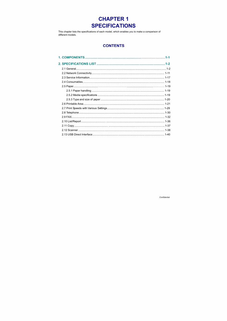
1. COMPONENTS
Fig. 1-1
LED ASSY
LVPS unit
Fuser unitPaper eject guide ASSY
Side cover R ASSY
High-voltage
HVPS control
Toner LED
Side frame R
Paper feed unitWaste toner sensor
Fuser cover
Back cover
Fuser ejectdrive ASSY
Belt drive ASSY
Main PCB ASSY
Engine PCB ASSY
Access cover
Side cover L ASSY Drum develop
Front cover ASSY
Toner/New sensor
ADF unit
Side frame L
Registration sensor
Paper tray
Top cover arm R
Top cover arm L
LED head controlPCB ASSY
drive unit
PCB ASSY
holder ASSY
Main fan ASSY
LV fan ASSY
PCB ASSY
power supply
PCB ASSY
Document scanner unit Panel unit
Joint cover sub ASSY
Front cover
NCU PCB ASSY
Speaker unit
top ASSY
PCB ASSY
USB direct interfacerelay PCB ASSY
holder ASSY
7/18/2019 Brother Mfc 9125cn 9325cw en 5694 Mfp Sm
http://slidepdf.com/reader/full/brother-mfc-9125cn-9325cw-en-5694-mfp-sm 14/597
1-2 Confidential
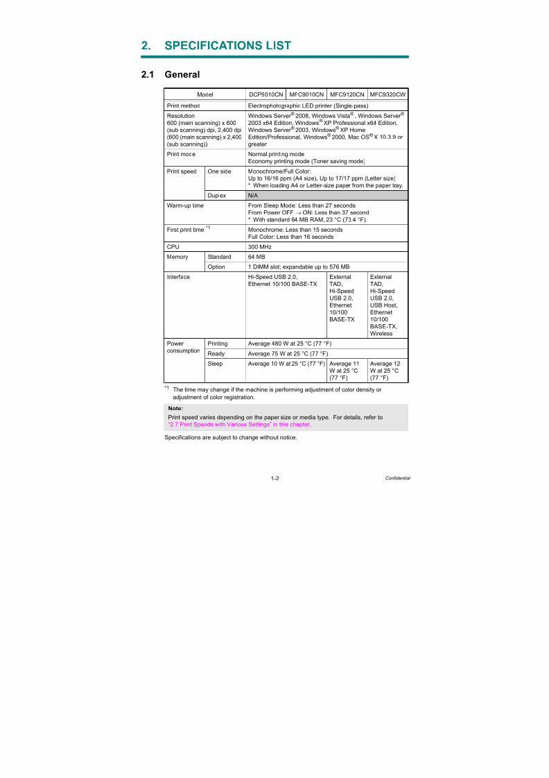
2. SPECIFICATIONS LIST
2.1 General
*1 The time may change if the machine is performing adjustment of color density or
adjustment of color registration.
Specifications are subject to change without notice.
Model DCP9010CN MFC9010CN MFC9120CN MFC9320CW
Print method Electrophotographic LED printer (Single-pass)
Resolution
600 (main scanning) x 600
(sub scanning) dpi, 2,400 dpi
(600 (main scanning) x 2,400
(sub scanning))
Windows Server ® 2008, Windows Vista® , Windows Server ®
2003 x64 Edition, Windows® XP Professional x64 Edition,
Windows Server ® 2003, Windows® XP Home
Edition/Professional, Windows® 2000, Mac OS®
X 10.3.9 or
greater
Print mode Normal printing mode
Economy printing mode (Toner saving mode)
Print speed One side Monochrome/Full Color:
Up to 16/16 ppm (A4 size), Up to 17/17 ppm (Letter size)
* When loading A4 or Letter-size paper from the paper tray.
Duplex N/A
Warm-up time From Sleep Mode: Less than 27 seconds
From Power OFF→ ON: Less than 37 second
* With standard 64 MB RAM, 23 °C (73.4 °F).
First print time *1 Monochrome: Less than 15 seconds
Full Color: Less than 16 seconds
CPU 300 MHz
Memory Standard 64 MB
Option 1 DIMM slot; expandable up to 576 MB
Interface Hi-Speed USB 2.0,
Ethernet 10/100 BASE-TX
External
TAD,
Hi-Speed
USB 2.0,
Ethernet
10/100
BASE-TX
External
TAD,
Hi-Speed
USB 2.0,
USB Host,
Ethernet
10/100
BASE-TX,
Wireless
Power
consumption
Printing Average 480 W at 25 °C (77 °F)
Ready Average 75 W at 25 °C (77 °F)
Sleep Average 10 W at 25 °C (77 °F) Average 11
W at 25 °C
(77 °F)
Average 12
W at 25 °C
(77 °F)
Note:
Print speed varies depending on the paper size or media type. For details, refer to
“2.7 Print Speeds with Various Settings” in this chapter .
7/18/2019 Brother Mfc 9125cn 9325cw en 5694 Mfp Sm
http://slidepdf.com/reader/full/brother-mfc-9125cn-9325cw-en-5694-mfp-sm 15/597
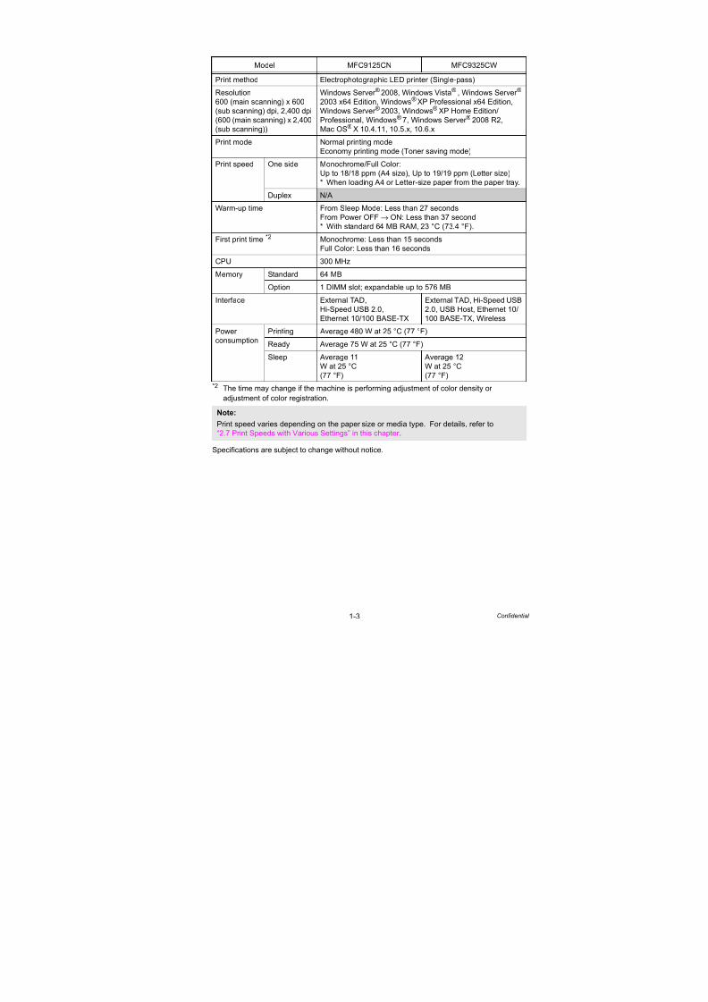
1-3 Confidential
*2 The time may change if the machine is performing adjustment of color density or
adjustment of color registration.
Specifications are subject to change without notice.
Model MFC9125CN MFC9325CW
Print method Electrophotographic LED printer (Single-pass)
Resolution
600 (main scanning) x 600
(sub scanning) dpi, 2,400 dpi(600 (main scanning) x 2,400
(sub scanning))
Windows Server ® 2008, Windows Vista® , Windows Server ®
2003 x64 Edition, Windows® XP Professional x64 Edition,
Windows Server ®
2003, Windows®
XP Home Edition/Professional, Windows®
7, Windows Server ® 2008 R2,
Mac OS® X 10.4.11, 10.5.x, 10.6.x
Print mode Normal printing mode
Economy printing mode (Toner saving mode)
Print speed One side Monochrome/Full Color:
Up to 18/18 ppm (A4 size), Up to 19/19 ppm (Letter size)
* When loading A4 or Letter-size paper from the paper tray.
Duplex N/A
Warm-up time From Sleep Mode: Less than 27 seconds
From Power OFF→ ON: Less than 37 second
* With standard 64 MB RAM, 23 °C (73.4 °F).
First print time *2 Monochrome: Less than 15 seconds
Full Color: Less than 16 seconds
CPU 300 MHz
Memory Standard 64 MB
Option 1 DIMM slot; expandable up to 576 MB
Interface External TAD,
Hi-Speed USB 2.0,
Ethernet 10/100 BASE-TX
External TAD, Hi-Speed USB
2.0, USB Host, Ethernet 10/
100 BASE-TX, Wireless
Power
consumption
Printing Average 480 W at 25 °C (77 °F)
Ready Average 75 W at 25 °C (77 °F)
Sleep Average 11
W at 25 °C
(77 °F)
Average 12
W at 25 °C
(77 °F)
Note:
Print speed varies depending on the paper size or media type. For details, refer to
“2.7 Print Speeds with Various Settings” in this chapter .
7/18/2019 Brother Mfc 9125cn 9325cw en 5694 Mfp Sm
http://slidepdf.com/reader/full/brother-mfc-9125cn-9325cw-en-5694-mfp-sm 16/597
1-4 Confidential
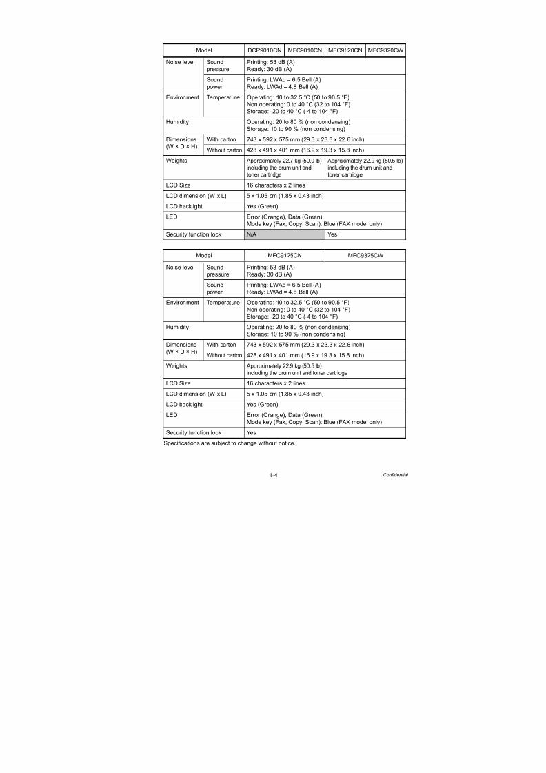
Specifications are subject to change without notice.
Model DCP9010CN MFC9010CN MFC9120CN MFC9320CW
Noise level Sound
pressure
Printing: 53 dB (A)
Ready: 30 dB (A)
Sound
power
Printing: LWAd = 6.5 Bell (A)
Ready: LWAd = 4.8 Bell (A)
Environment Temperature Operating: 10 to 32.5 °C (50 to 90.5 °F)
Non operating: 0 to 40 °C (32 to 104 °F)
Storage: -20 to 40 °C (-4 to 104 °F)
Humidity Operating: 20 to 80 % (non condensing)
Storage: 10 to 90 % (non condensing)
Dimensions
(W × D × H)
With carton 743 x 592 x 575 mm (29.3 x 23.3 x 22.6 inch)
Without carton 428 x 491 x 401 mm (16.9 x 19.3 x 15.8 inch)
Weights Approximately 22.7 kg (50.0 lb)
including the drum unit and
toner cartridge
Approximately 22.9 kg (50.5 lb)
including the drum unit and
toner cartridge
LCD Size 16 characters x 2 lines
LCD dimension (W x L) 5 x 1.05 cm (1.85 x 0.43 inch)
LCD backlight Yes (Green)
LED Error (Orange), Data (Green),
Mode key (Fax, Copy, Scan): Blue (FAX model only)
Security function lock N/A Yes
Model MFC9125CN MFC9325CW
Noise level Sound
pressure
Printing: 53 dB (A)
Ready: 30 dB (A)
Sound
power
Printing: LWAd = 6.5 Bell (A)
Ready: LWAd = 4.8 Bell (A)
Environment Temperature Operating: 10 to 32.5 °C (50 to 90.5 °F)
Non operating: 0 to 40 °C (32 to 104 °F)
Storage: -20 to 40 °C (-4 to 104 °F)
Humidity Operating: 20 to 80 % (non condensing)
Storage: 10 to 90 % (non condensing)
Dimensions
(W × D × H)
With carton 743 x 592 x 575 mm (29.3 x 23.3 x 22.6 inch)
Without carton 428 x 491 x 401 mm (16.9 x 19.3 x 15.8 inch)
Weights Approximately 22.9 kg (50.5 lb)
including the drum unit and toner cartridge
LCD Size 16 characters x 2 lines
LCD dimension (W x L) 5 x 1.05 cm (1.85 x 0.43 inch)
LCD backlight Yes (Green)
LED Error (Orange), Data (Green),
Mode key (Fax, Copy, Scan): Blue (FAX model only)
Security function lock Yes

7/18/2019 Brother Mfc 9125cn 9325cw en 5694 Mfp Sm
http://slidepdf.com/reader/full/brother-mfc-9125cn-9325cw-en-5694-mfp-sm 17/597
1-5 Confidential
<PC software>
*3 Download from http://solutions.brother.com/
<Viewer>
*4
PaperPort 11 SE supports Microsoft®
Windows Vista®
or Windows®
XP (SP 2 or higher) orWindows® 2000 (SP4 or higher) only
<PC-Fax>*5
*5 Not available for Color Fax
Specifications are subject to change without notice.
Model DCP9010CN MFC9010CN MFC9120CN MFC9320CW
Printer driver Windows® Host-Based Driver for Windows Server ® 2008, Windows
Vista®, Windows Server ® 2003 x64 Edition, Windows® XP
Professional x64 Edition, Windows Server ® 2003, Windows®
XP Home Edition/Professional, Windows® 2000 Professional
BR-Script 3 (PPD file for Windows Server ® 2008, Windows
Vista®, Windows Server ® 2003 x64 Edition, Windows® XP
Professional x64 Edition, Windows Server ® 2003, Windows®
XP Home Edition/Professional, Windows® 2000 Professional)
Macintosh® Macintosh Printer Driver for Mac OS® X 10.3.9 or greater
BR-Script 3 (PPD file for Mac OS® X 10.3.9 or greater)
Linux*3 Linux printer driver for CUPS printing system (x86, x64
environment)
Linux printer driver for LPD/LPRng printing system (x86, x64
environment)
Model DCP9010CN MFC9010CN MFC9120CN MFC9320CW
Viewer Windows® PaperPort 11 SE*4, Page Manager 7 (China)
Macintosh® Page Manager 7
Linux N/A
Model DCP9010CN MFC9010CN MFC9120CN MFC9320CW
Windows® Send N/A Yes (FaxShare Software by
Brother)
Receive N/A Yes (for Windows Vista®/
Windows® XP/ Windows®
2000)
Macintosh® Send N/A Yes (FaxShare Software by
Brother)
Receive N/A
Linux Send N/A Yes (LPR/CUPS PC-FAX
Send Driver)
Receive N/A

7/18/2019 Brother Mfc 9125cn 9325cw en 5694 Mfp Sm
http://slidepdf.com/reader/full/brother-mfc-9125cn-9325cw-en-5694-mfp-sm 18/597
1-6 Confidential
<PC software>
*6 Download from http://solutions.brother.com/
<Viewer>
*7 PaperPort 11 SE supports Microsoft® Windows Vista® or Windows® XP (SP 2 or higher) or
Windows® 2000 (SP4 or higher) only
<PC-Fax>*8
*8 Not available for Color Fax
Specifications are subject to change without notice.
Model MFC9125CN MFC9325CW
Printer driver Windows® Host-Based Driver for Windows® XP, Windows®
XP
Professional x64 Edition, Windows Vista®, Windows® 7,
Windows Server ® 2003, Windows Server ® 2003 x64 Edition,
Windows Server ® 2008, Windows Server ® 2008 R2 Edition
BR-Script3 (PPD file) for Windows® XP, Windows®
XP
Professional x64 Edition, Windows Vista®, Windows® 7,
Windows Server ® 2003, Windows Server ® 2003 x64 Edition,
Windows Server ® 2008, Windows Server ® 2008 R2 Edition
Macintosh® Macintosh Printer Driver for Mac OS® X 10.4.11, 10.5.x,
10.6.x
BR-Script 3 (PPD file for Mac OS® X 10.4.11, 10.5.x, 10.6.x
Linux*6 Linux printer driver for CUPS printing system (x86, x64
environment)
Linux printer driver for LPD/LPRng printing system (x86, x64environment)
Model MFC9125CN MFC9325CW
Viewer Windows® PaperPort 11 SE*7
Macintosh® Page Manager 9
Linux N/A
Model MFC9125CN MFC9325CW
Windows® Send Yes (FaxShare Software by Brother)
Receive Yes (for Windows Vista®/Windows® XP/ Windows® 2007)
Macintosh® Send Yes (FaxShare Software by Brother)
Receive N/ALinux Send Yes (LPR/CUPS PC-FAX Send Driver)
Receive N/A
7/18/2019 Brother Mfc 9125cn 9325cw en 5694 Mfp Sm
http://slidepdf.com/reader/full/brother-mfc-9125cn-9325cw-en-5694-mfp-sm 19/597
1-7 Confidential
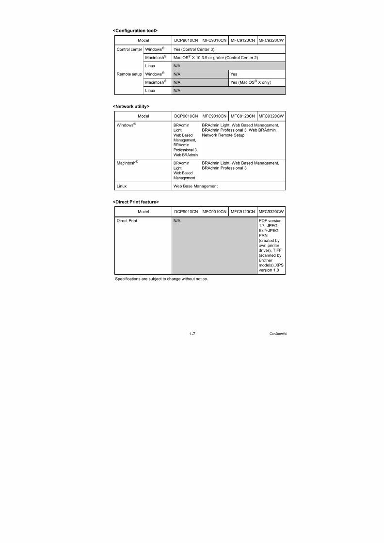
<Configuration tool>
<Network utility>
<Direct Print feature>
Specifications are subject to change without notice.
Model DCP9010CN MFC9010CN MFC9120CN MFC9320CW
Control center Windows® Yes (Control Center 3)
Macintosh® Mac OS® X 10.3.9 or grater (Control Center 2)
Linux N/A
Remote setup Windows® N/A Yes
Macintosh® N/A Yes (Mac OS® X only)
Linux N/A
Model DCP9010CN MFC9010CN MFC9120CN MFC9320CW
Windows® BRAdmin
Light,
Web Based
Management,
BRAdmin
Professional 3,
Web BRAdmin
BRAdmin Light, Web Based Management,
BRAdmin Professional 3, Web BRAdmin,
Network Remote Setup
Macintosh® BRAdmin
Light,
Web Based
Management
BRAdmin Light, Web Based Management,
BRAdmin Professional 3
Linux Web Base Management
Model DCP9010CN MFC9010CN MFC9120CN MFC9320CW
Direct Print N/A PDF version
1.7, JPEG,
Exif+JPEG,
PRN
(created by
own printerdriver), TIFF
(scanned by
Brother
models), XPS
version 1.0
7/18/2019 Brother Mfc 9125cn 9325cw en 5694 Mfp Sm
http://slidepdf.com/reader/full/brother-mfc-9125cn-9325cw-en-5694-mfp-sm 20/597
1-8 Confidential
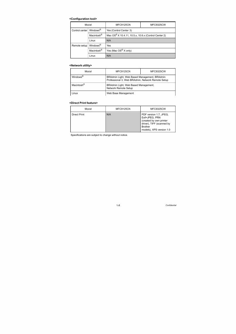
<Configuration tool>
<Network utility>
<Direct Print feature>
Specifications are subject to change without notice.
Model MFC9125CN MFC9325CW
Control center Windows® Yes (Control Center 3)
Macintosh® Mac OS® X 10.4.11, 10.5.x, 10.6.x (Control Center 2)
Linux N/A
Remote setup Windows® Yes
Macintosh® Yes (Mac OS® X only)
Linux N/A
Model MFC9125CN MFC9325CW
Windows® BRAdmin Light, Web Based Management, BRAdmin
Professional 3, Web BRAdmin, Network Remote Setup
Macintosh® BRAdmin Light, Web Based Management,
Network Remote Setup
Linux Web Base Management
Model MFC9125CN MFC9325CW
Direct Print N/A PDF version 1.7, JPEG,
Exif+JPEG, PRN
(created by own printer
driver), TIFF (scanned by
Brother
models), XPS version 1.0

7/18/2019 Brother Mfc 9125cn 9325cw en 5694 Mfp Sm
http://slidepdf.com/reader/full/brother-mfc-9125cn-9325cw-en-5694-mfp-sm 21/597
1-9 Confidential
<System requirements>
(DCP9010CN/MFC9010CN/MFC9120CN/MFC9320CW)
*9 Internet Explorer ® 5.5 or greater.*10 For WIA, 1,200 (main scanning) x 1,200 (sub scanning) resolution. Brother Scanner Utility
enables to enhance up to 19,200 (main scanning) x 19,200 (sub scanning) dpi.
Specifications are subject to change without notice.
Computer platform &
Operating system versionProcessor speed
Minimum
RAM
Recom-
mended
RAM
Available
hard disk
space
Windows® *9 Windows
Server ® 2008
Intel® Pentium® 4
or equivalent
64-bit
(Intel® 64 or
AMD64)
supported CPU
512 MB 2 GB 50 MB
Windows
Vista® *10
512 MB 1 GB 500 MB
Windows
Server ® 2003
x64 Edition
64-bit
(Intel® 64 or AMD64)
supported CPU
256 MB 512MB 50 MB
Windows® XP
Professionalx64 Edition
150 MB
Windows
Server ® 2003
Intel® Pentium® III
or equivalent
256 MB 512 MB 50 MB
Windows®
XP Home
Edition*10
Intel® Pentium® II
or equivalent
128 MB 256 MB 150 MB
Windows® XP
Professional*10
Windows®
2000
Professional
64 MB 256 MB 150 MB
Macintosh® Mac OS®
X
10.4.4 or
greater
Power PC G4/G5,
Intel® Core™
Processor
512 MB 1 GB 80 MB
Mac OS® X
10.3.9 -10.4.3
Power PC G4/G5,
Intel® Core™
Solo/Duo, Power
PC G3 350 MHz
128 MB 256 MB

7/18/2019 Brother Mfc 9125cn 9325cw en 5694 Mfp Sm
http://slidepdf.com/reader/full/brother-mfc-9125cn-9325cw-en-5694-mfp-sm 22/597
1-10 Confidential
(MFC9125CN/MFC9325CW)
*11 Internet Explorer ® 5.5 or greater.
*12 For WIA, 1200x1200 resolution. Brother Scanner Utility enables to enhance up to 19200 x
19200 dpi.
*13 PaperPortTM 11SE supports Microsoft® SP2 or higher for Windows® XP.
Specifications are subject to change without notice.
Computer platform &
Operating system versionProcessor speed
Minimum
RAM
Recom-
mended
RAM
Available
hard disk
space
Windows
®
*11 Windows
®
XPHome*12, *13,
Windows® XP
Professional*12, *13
Intel
®
Pentium
®
II orequivalent 128 MB 256 MB 150 MB
Windows® XP
Professional
x64 Edition*12
64-bit
(Intel®64 or AMD64)
supported CPU
256 MB 512 MB 150 MB
Windows Vista®
*12Intel® Pentium® 4 or
equivalent
64-bit
(Intel®64 or AMD64)
supported CPU
512 MB 1 GB 500 MB
Windows® 7*12 Intel® Pentium® 4 or
equivalent 64-bit
(Intel®64 or AMD64)
supported CPU
1 GB
(32-bit)
2 GB
(64-bit)
1 GB
(32-bit)
2 GB
(64-bit)
650 MB
Windows
Server ® 2003
(print only via
network)
Intel® Pentium® III or
equivalent
256 MB 512 MB 50 MB
Windows
Server ® 2003x64 Edition
(print only via
network)
64-bit
(Intel®64 or AMD64)supported CPU
256 MB 512 MB 50 MB
Windows
Server ® 2008
(print only via
network)
Intel® Pentium® 4 or
equivalent 64-bit
(Intel®64 or AMD64)
supported CPU
512 MB 2 GB 50 MB
Windows
Server ® 2008
R2 (print only
via network)
64-bit
(Intel®64 or AMD64)
supported CPU
512 MB 2 GB 50 MB
Macintosh® Mac OS®
X
10.4.11, 10.5.x
Power PC G4/G5,
Intel® Processor
512 MB 1 GB 80 MB
Mac OS® X
10.6.x
Intel® Processor 1 GB 2 GB

7/18/2019 Brother Mfc 9125cn 9325cw en 5694 Mfp Sm
http://slidepdf.com/reader/full/brother-mfc-9125cn-9325cw-en-5694-mfp-sm 23/597
1-11 Confidential
2.2 Network Connectivity
<Wired network>
(DCP9010CN/MFC9010CN/MFC9120CN/MFC9320CW)
*1 If you want to use the IPv6 protocol, visit http://solutions.brother.com/ for more information.*2 BRAdmin Professional and Web BRAdmin are available as a download from
http://solutions.brother.com/
Specifications are subject to change without notice.
Network node type NC-6700h
Operating system
support
Windows Server ® 2008, Windows Vista®, Windows Server ® 2003
x64 Edition, Windows® XP Professional x64 Edition, Windows
Server ® 2003, Windows® XP Home Edition/Professional, Windows®
2000 Professional, Mac OS® X 10.3.9 or greater
Protocol support TCP/IP: IPv4 ARP, RARP, BOOTP, DHCP, APIPA (Auto IP), WINS/
NetBIOS name resolution, DNS resolver, mDNS,
LLMNR responder, LPR/LPD, Custom Raw Port/
Port9100, IPP/IPPS, FTP Server, TELNET Server,
HTTP/HTTPS server, TFTP client and server, SMTP
Client, APOP, POP before SMTP, SMTP-AUTH,
SNMPv1/v2c/v3, ICMP, LLTD responder, Web
Services Print, SSL/TLS, CIFS client, SNTP, FTP clientTCP/IP: IPv6*1 (Turned off as default) NDP, RA, DNS resolver, mDNS,
LLMNR responder, LPR/LPD, Custom Raw Port/
Port9100, IPP/IPPS, FTP Server, TELNET Server,
HTTP/HTTPS server, TFTP client and server, SMTP
Client, APOP, POP before SMTP, SMTP-AUTH,
SNMPv1/v2c/v3, ICMPv6, LLTD responder, Web
Services Print, SSL/TLS, CIFS client, SNTP, FTP client
Network type Ethernet 10/100 BASE-TX Auto Negotiation
Network printing Windows Server ® 2008, Windows Vista®, Windows Server ® 2003,
Windows® XP and Windows® 2000 TCP/IP printing
Mac OS®
X 10.3.9 or greater printingManagement utility BRAdmin
Professional 3*2Windows Server ® 2008, Windows Vista®,
Windows Server ® 2003 x64 Edition, Windows® XP
Professional x64 Edition, Windows Server ® 2003,
Windows® XP Home Edition/Professional Edition,
Windows® 2000 Professional
Web
BRAdmin*2Windows Server ® 2008, Windows Vista®,
Windows Server ® 2003 x64 Edition, Windows® XP
Professional x64 Edition, Windows Server ® 2003,
Windows® XP Home Edition/Professional Edition,
Windows® 2000 Professional
Web BasedManagement
Microsoft Internet Explorer 6.0 (or greater),Firefox 1.0 (or greater) for Windows, and Safari 1.2
(or greater) for Macintosh are recommended.
BRAdmin Light Windows Server ® 2008, Windows Vista®,
Windows Server ® 2003 x64 Edition, Windows® XP
Professional x64 Edition, Windows Server ® 2003,
Windows® XP Home Edition/Professional Edition,
Windows® 2000 Professional
Mac OS® X 10.3.9 or greater

7/18/2019 Brother Mfc 9125cn 9325cw en 5694 Mfp Sm
http://slidepdf.com/reader/full/brother-mfc-9125cn-9325cw-en-5694-mfp-sm 24/597
1-12 Confidential
(MFC9125CN/MFC9325CW)
*3 If you want to use the IPv6 protocol, visit http://solutions.brother.com/ for more information.
*4 BRAdmin Professional and Web BRAdmin are available as a download from
http://solutions.brother.com/
Specifications are subject to change without notice.
Network node type NC-6700h
Operating system
support
Windows Server ® 2008, Windows Vista®, Windows Server ® 2003
x64 Edition, Windows® XP Professional x64 Edition, Windows
Server ® 2003, Windows® XP Home Edition/Professional, Windows®
7, Windows Server ® 2008 R2, Mac OS® X 10.4.11, 10.5.x, 10.6.x
Protocol support TCP/IP: IPv4 ARP, RARP, BOOTP, DHCP, APIPA (Auto IP), WINS/
NetBIOS name resolution, DNS resolver, mDNS,
LLMNR responder, LPR/LPD, Custom Raw Port/
Port9100, IPP/IPPS, FTP Server, TELNET Server,
HTTP/HTTPS server, TFTP client and server, SMTP
Client, APOP, POP before SMTP, SMTP-AUTH,
SNMPv1/v2c/v3, ICMP, LLTD responder, Web
Services Print, SSL/TLS, CIFS client, SNTP, FTP client
TCP/IP: IPv6*3 (Turned off as default) NDP, RA, DNS resolver, mDNS,
LLMNR responder, LPR/LPD, Custom Raw Port/
Port9100, IPP/IPPS, FTP Server, TELNET Server,HTTP/HTTPS server, TFTP client and server, SMTP
Client, APOP, POP before SMTP, SMTP-AUTH,
SNMPv1/v2c/v3, ICMPv6, LLTD responder, Web
Services Print, SSL/TLS, CIFS client, SNTP, FTP client
Network type Ethernet 10/100 BASE-TX Auto Negotiation
Network printing Windows Server ® 2008, Windows Vista®, Windows Server ® 2003,
Windows® XP, Windows® 7 and Windows Server ® 2008 R2 TCP/IP
printing
Mac OS® X 10.4.11, 10.5.x, 10.6.x printing
Management utility BRAdmin
Professional 3*4
Windows Server ® 2008, Windows Vista®,
Windows Server ®
2003 x64 Edition, Windows®
XPProfessional x64 Edition, Windows Server ® 2003,
Windows® XP Home Edition/Professional Edition,
Windows® 7, Windows Server ® 2008 R2
Web
BRAdmin*4Windows Server ® 2008, Windows Vista®,
Windows Server ® 2003 x64 Edition, Windows® XP
Professional x64 Edition, Windows Server ® 2003,
Windows® XP Home Edition/Professional Edition,
Windows® 7, Windows Server ® 2008 R2
Web Based
Management
Microsoft Internet Explorer 6.0 (or greater),
Firefox 1.0 (or greater) for Windows, and Safari 1.2
(or greater) for Macintosh are recommended.
BRAdmin Light Windows Server ® 2008, Windows Vista®,
Windows Server ® 2003 x64 Edition, Windows® XP
Professional x64 Edition, Windows Server ® 2003,
Windows® XP Home Edition/Professional Edition,
Windows® 7, Windows Server ® 2008 R2
Mac OS® X 10.4.11, 10.5.x, 10.6.x

7/18/2019 Brother Mfc 9125cn 9325cw en 5694 Mfp Sm
http://slidepdf.com/reader/full/brother-mfc-9125cn-9325cw-en-5694-mfp-sm 25/597
1-13 Confidential
<Wireless network>(MFC9320CW)
*5 If you want to use the IPv6 protocol, visit http://solutions.brother.com/ for more information.
Specifications are subject to change without notice.
Network node type NC-7500w
Operating system
support
Windows Server ® 2008, Windows Vista®, Windows Server ® 2003
x64 Edition, Windows® XP Professional x64 Edition, Windows
Server ® 2003, Windows® XP Home Edition/Professional, Windows®
2000 Professional, Mac OS® X 10.3.9 or greater
Protocol support TCP/IP: IPv4 ARP, RARP, BOOTP, DHCP, APIPA (Auto IP),
WINS/NetBIOS name resolution, DNS Resolver,
mDNS, LLMNR responder, LPR/LPD, Custom
Raw Port/Port9100, IPP/IPPS, FTP Server,
TELNET Server, HTTP/HTTPS server, TFTP
client and server, SMTP Client, APOP, POP before
SMTP, SMTP-AUTH, SNMPv1/v2c/v3, ICMP,
LLTD responder, Web Services Print, SSL/TLS,
CIFS client
TCP/IP: IPv6*5 NDP, RA, DNS resolver, mDNS, LLMNR
responder, LPR/LPD, Custom Raw Port/
Port9100, IPP/IPPS, FTP Server, TELNET
Server, HTTP/HTTPS server, TFTP client and
server, SMTP Client, APOP, POP before SMTP,
SMTP-AUTH, SNMPv1/v2c/v3, ICMPv6, LLTD
responder, Web Services Print, SSL/TLS,
CIFS client
Network type IEEE 802.11 b/g wireless
Frequency 2412 - 2472 MHz
RF channels US/Canada 1 - 11
Japan 802.11 b: 1 - 14, 802.11 g: 1 - 13
Others 1 - 13
Communication mode Infrastructure, Ad-hoc (802.11 b only)
Data rate 802.11 b 11/5.5/2/1 Mbps
802.11 g 54/48/36/24/18/12/11/9/6/5.5/2/1 Mbps
Link distance 70 m (233 ft.) at lowest data rate (The distance rate will vary upon
environment and other equipment location.)
Network security SSID/ESSID, WEP 64/128 bit, WPA-PSK (TKIP/AES),WPA2-PSK (AES), LEAP (CKIP), EAP-FAST (TKIP/AES)
Network printing Windows Vista®, Windows Server ® 2003, Windows® XP and
Windows® 2000 TCP/IP printing
Mac OS® X 10.3.9 or greater printing

7/18/2019 Brother Mfc 9125cn 9325cw en 5694 Mfp Sm
http://slidepdf.com/reader/full/brother-mfc-9125cn-9325cw-en-5694-mfp-sm 26/597
1-14 Confidential
*6 BRAdmin Professional and Web BRAdmin are available as a download from
http://solutions.brother.com/
Specifications are subject to change without notice.
Management utility BRAdmin
Professional 3*6Windows Server ® 2008, Windows Vista®,
Windows Server ® 2003 x64 Edition, Windows®
XP Professional x64 Edition, Windows Server ®
2003, Windows® XP Home Edition/Professional
Edition, Windows® 2000 Professional
Web
BRAdmin*6Windows Server ® 2008, Windows Vista®,
Windows Server ® 2003 x64 Edition, Windows®
XP Professional x64 Edition, Windows Server ®
2003, Windows® XP Home Edition/Professional
Edition, Windows® 2000 Professional
Web Based
Management
Microsoft Internet Explorer 6.0 (or greater),
Firefox 1.0 (or greater) for Windows, and Safari
1.2 (or greater) for Macintosh are recommended.
BRAdmin Light Windows Server ® 2008, Windows Vista®,
Windows Server ® 2003 x64 Edition, Windows®
XP Professional x64 Edition, Windows Server ®
2003, Windows® XP Home Edition/Professional
Edition, Windows® 2000 Professional
Mac OS® X 10.3.9 or greater
7/18/2019 Brother Mfc 9125cn 9325cw en 5694 Mfp Sm
http://slidepdf.com/reader/full/brother-mfc-9125cn-9325cw-en-5694-mfp-sm 27/597
1-15 Confidential
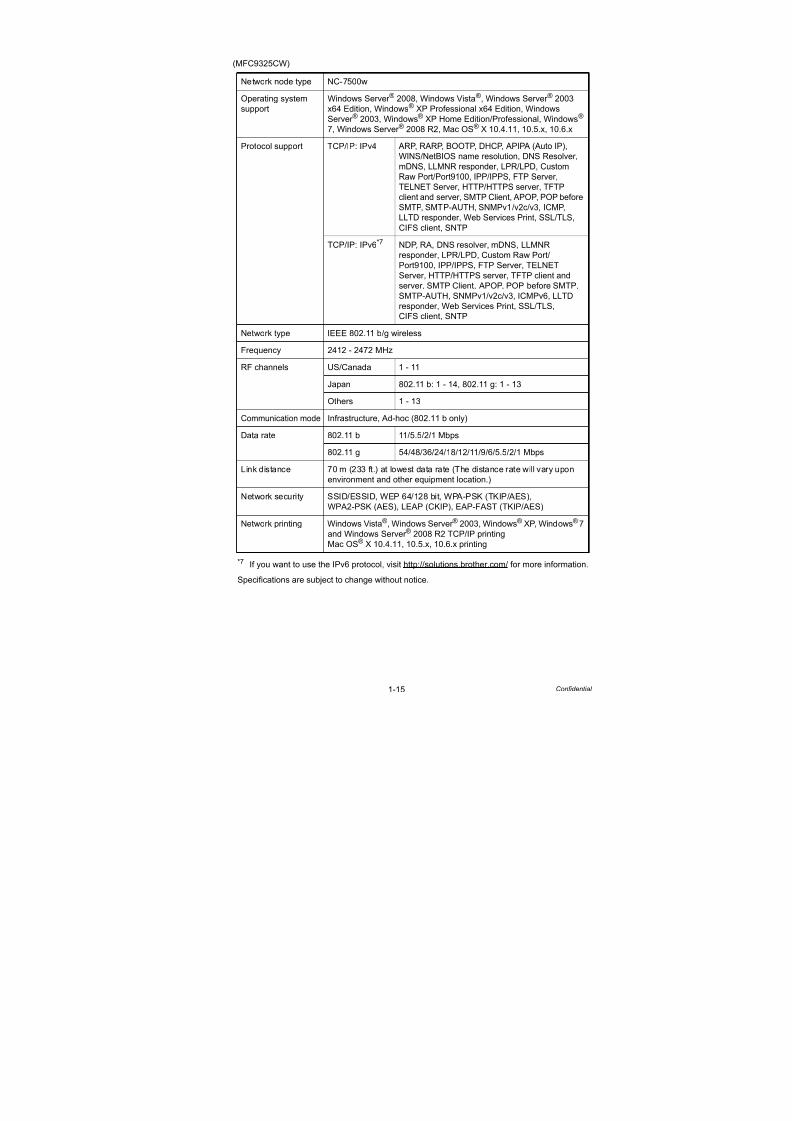
(MFC9325CW)
*7 If you want to use the IPv6 protocol, visit http://solutions.brother.com/ for more information.
Specifications are subject to change without notice.
Network node type NC-7500w
Operating system
support
Windows Server ® 2008, Windows Vista®, Windows Server ® 2003
x64 Edition, Windows® XP Professional x64 Edition, Windows
Server ® 2003, Windows® XP Home Edition/Professional, Windows®
7, Windows Server ® 2008 R2, Mac OS® X 10.4.11, 10.5.x, 10.6.x
Protocol support TCP/IP: IPv4 ARP, RARP, BOOTP, DHCP, APIPA (Auto IP),
WINS/NetBIOS name resolution, DNS Resolver,
mDNS, LLMNR responder, LPR/LPD, Custom
Raw Port/Port9100, IPP/IPPS, FTP Server,
TELNET Server, HTTP/HTTPS server, TFTP
client and server, SMTP Client, APOP, POP before
SMTP, SMTP-AUTH, SNMPv1/v2c/v3, ICMP,
LLTD responder, Web Services Print, SSL/TLS,
CIFS client, SNTP
TCP/IP: IPv6*7 NDP, RA, DNS resolver, mDNS, LLMNR
responder, LPR/LPD, Custom Raw Port/Port9100, IPP/IPPS, FTP Server, TELNET
Server, HTTP/HTTPS server, TFTP client and
server, SMTP Client, APOP, POP before SMTP,
SMTP-AUTH, SNMPv1/v2c/v3, ICMPv6, LLTD
responder, Web Services Print, SSL/TLS,
CIFS client, SNTP
Network type IEEE 802.11 b/g wireless
Frequency 2412 - 2472 MHz
RF channels US/Canada 1 - 11
Japan 802.11 b: 1 - 14, 802.11 g: 1 - 13
Others 1 - 13
Communication mode Infrastructure, Ad-hoc (802.11 b only)
Data rate 802.11 b 11/5.5/2/1 Mbps
802.11 g 54/48/36/24/18/12/11/9/6/5.5/2/1 Mbps
Link distance 70 m (233 ft.) at lowest data rate (The distance rate will vary upon
environment and other equipment location.)
Network security SSID/ESSID, WEP 64/128 bit, WPA-PSK (TKIP/AES),
WPA2-PSK (AES), LEAP (CKIP), EAP-FAST (TKIP/AES)
Network printing Windows Vista®, Windows Server ® 2003, Windows® XP, Windows® 7
and Windows Server ® 2008 R2 TCP/IP printing
Mac OS® X 10.4.11, 10.5.x, 10.6.x printing

7/18/2019 Brother Mfc 9125cn 9325cw en 5694 Mfp Sm
http://slidepdf.com/reader/full/brother-mfc-9125cn-9325cw-en-5694-mfp-sm 28/597
1-16 Confidential
*8 BRAdmin Professional and Web BRAdmin are available as a download from
http://solutions.brother.com/
Specifications are subject to change without notice.
Management utility BRAdmin
Professional 3*8Windows Server ® 2008, Windows Vista®,
Windows Server ® 2003 x64 Edition, Windows®
XP Professional x64 Edition, Windows Server ®
2003, Windows® XP Home Edition/Professional
Edition, Windows® 7, Windows Server ® 2008 R2
Web
BRAdmin*8Windows Server ® 2008, Windows Vista®,
Windows Server ® 2003 x64 Edition, Windows®
XP Professional x64 Edition, Windows Server ®
2003, Windows® XP Home Edition/Professional
Edition, Windows® 7, Windows Server ® 2008 R2
Web Based
Management
Microsoft Internet Explorer 6.0 (or greater),
Firefox 1.0 (or greater) for Windows, and Safari
1.2 (or greater) for Macintosh are recommended.
BRAdmin Light Windows Server ® 2008, Windows Vista®,
Windows Server ® 2003 x64 Edition, Windows®
XP Professional x64 Edition, Windows Server ®
2003, Windows® XP Home Edition/Professional
Edition, Windows® 7, Windows Server ® 2008 R2
Mac OS® X 10.4.11, 10.5.x, 10.6.x

7/18/2019 Brother Mfc 9125cn 9325cw en 5694 Mfp Sm
http://slidepdf.com/reader/full/brother-mfc-9125cn-9325cw-en-5694-mfp-sm 29/597
1-17 Confidential
2.3 Service Information
These are key service information to maintain the product.
- Machine life: approximately 100,000 pages or 5 years
- MTBF (Meantime between failure): 4,000 hours
- MTTR (Meantime to repair): 30 minutes
- Maximum monthly volume: 25,000 pages
- Periodical maintenance parts:
* As for replacement of the periodical maintenance parts, refer to “PERIODICAL
MAINTENANCE” in Chapter 4.
Specifications are subject to change without notice.
Part Approximate life
Fuser unit 50,000 pages
Paper feeding kit 50,000 pages
ADF unit 50,000 pages or 5 years
Document scanner unit 50,000 pages or 5 years
7/18/2019 Brother Mfc 9125cn 9325cw en 5694 Mfp Sm
http://slidepdf.com/reader/full/brother-mfc-9125cn-9325cw-en-5694-mfp-sm 30/597
1-18 Confidential
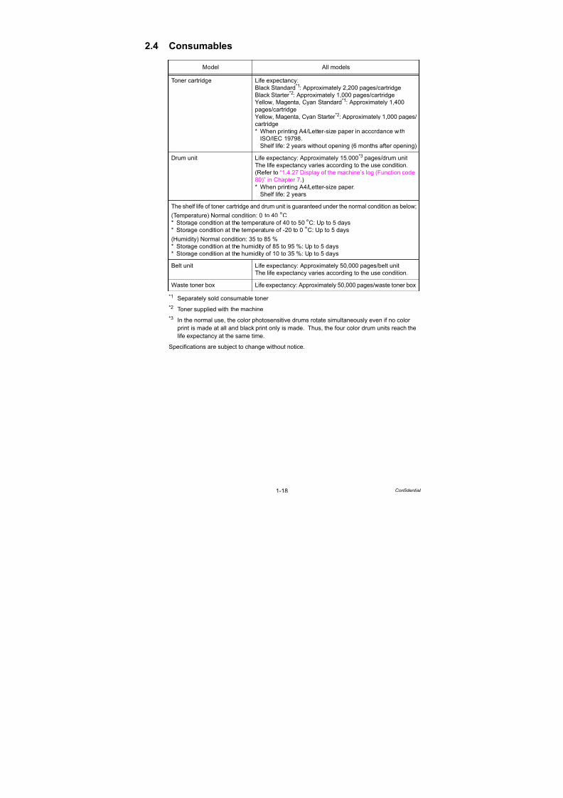
2.4 Consumables
*1 Separately sold consumable toner
*2 Toner supplied with the machine
*3 In the normal use, the color photosensitive drums rotate simultaneously even if no color
print is made at all and black print only is made. Thus, the four color drum units reach the
life expectancy at the same time.
Specifications are subject to change without notice.
Model All models
Toner cartridge Life expectancy:
Black Standard*1
: Approximately 2,200 pages/cartridgeBlack Starter *2: Approximately 1,000 pages/cartridge
Yellow, Magenta, Cyan Standard*1: Approximately 1,400
pages/cartridge
Yellow, Magenta, Cyan Starter *2: Approximately 1,000 pages/
cartridge
* When printing A4/Letter-size paper in accordance with
ISO/IEC 19798.
Shelf life: 2 years without opening (6 months after opening)
Drum unit Life expectancy: Approximately 15,000*3 pages/drum unit
The life expectancy varies according to the use condition.
(Refer to “1.4.27 Display of the machine’s log (Function code
80)” in Chapter 7.)* When printing A4/Letter-size paper.
Shelf life: 2 years
The shelf life of toner cartridge and drum unit is guaranteed under the normal condition as below;
(Temperature) Normal condition: 0 to 40 °C
* Storage condition at the temperature of 40 to 50 °C: Up to 5 days
* Storage condition at the temperature of -20 to 0 °C: Up to 5 days
(Humidity) Normal condition: 35 to 85 %
* Storage condition at the humidity of 85 to 95 %: Up to 5 days
* Storage condition at the humidity of 10 to 35 %: Up to 5 days
Belt unit Life expectancy: Approximately 50,000 pages/belt unit
The life expectancy varies according to the use condition.
Waste toner box Life expectancy: Approximately 50,000 pages/waste toner box

7/18/2019 Brother Mfc 9125cn 9325cw en 5694 Mfp Sm
http://slidepdf.com/reader/full/brother-mfc-9125cn-9325cw-en-5694-mfp-sm 31/597
1-19 Confidential
2.5 Paper
2.5.1 Paper handling
*1 Calculated with 80 g/m2 (20 lb) paper
2.5.2 Media specifications
*2 Legal size paper is not available in some regions outside the USA and Canada.
Specifications are subject to change without notice.
Model All models
Paper Input*1 Standard tray 250 sheets
Manual feed
slot
1 sheet
Option N/A
ADF Up to 35 sheets
Paper
output*1Face-down 100 sheets
Face-up 1 sheet (Straight paper path)
Duplex N/A
Model All models
Media type Paper tray Plain paper, Thin paper, Recycled paper
Manual feed
slot
Plain paper, Thin paper, Thick paper, Thicker paper,
Recycled paper, Bond paper, Label, Envelopes, Env. Thin,Env. Thick
Media
weight
Paper tray 60 to 105 g/m2 (16 to 28 lb)
Manual feed
slot
60 to 163 g/m2 (16 to 43 lb)
ADF 64 to 90 g/m2 (17 to 24 lb)
Media size Paper tray A4, Letter, B5 (ISO), A5, A5 (Long Edge), B6 (ISO), A6,
Executive, Legal*2, Folio
Manual feed
slot
Width: 76.2 to 220 mm (3.0 to 8.66 inch)
Length: 116 to 406.4 mm (4.57 to 16 inch)
ADF Width: 147.3 to 215.9 mm (5.8 to 8.5 inch)
Length: 147.3 to 356.0 mm (5.8 to 14.0 inch)

7/18/2019 Brother Mfc 9125cn 9325cw en 5694 Mfp Sm
http://slidepdf.com/reader/full/brother-mfc-9125cn-9325cw-en-5694-mfp-sm 32/597
1-20 Confidential
2.5.3 Type and size of paper
The printer loads paper from the installed paper tray or the manual feed slot. The names for
the paper trays in the printer driver as follows:
<Media type>
Specifications are subject to change without notice.
The name for the paper trays The name for the paper trays in the printer driver
Paper tray Tray
Manual feed slot Manual Feed
Tray Manual FeedChoose the media type
from the printer driver
Plain paper
60 to 105 g/m2
(16 to 28 lb)
Yes Yes Plain Paper
Recycled paper Yes Yes Recycled Paper
Bond paper
Rough paper-
60 to 163 g/m2
(16 to 43 lb)
N/A Yes
60 to 163 g/m2
(16 to 43 lb)
Bond Paper
Thick paper
105 to 163 g/m2
(28 to 43 lb)
N/A Yes Thick Paper or
Thicker Paper
Labels N/A Yes
A4 or Letter
Label
Envelopes N/A Yes Envelopes, Env. Thin,
Env. Thick
Memo:
- Use paper that is made for plain-paper copying.
- Use paper that is 75 to 90 g/m2 (20 to 24 lb).
- Use neutral paper. Do not use acidic or alkaline paper.
- Use long-grain paper.
- This machine can use recycled paper that meets DIN 19309 specifications.
- DO NOT use ink jet paper because it may cause a paper jam or damage your printer.

7/18/2019 Brother Mfc 9125cn 9325cw en 5694 Mfp Sm
http://slidepdf.com/reader/full/brother-mfc-9125cn-9325cw-en-5694-mfp-sm 33/597
1-21 Confidential
2.6 Printable Area
PCL5C emulation
When using PCL5C emulation, the edges of the paper that cannot be printed on are shown
below.
Specifications are subject to change without notice.
Note:
Therefore, the machine can only print within the shaded area when you use a PCL driver.
Portrait
A
B
C
D
E
F
GF
G
E
G G
Physical page
Printable area
Logical page
B Physical page length
D Maximum logical page length
F Distance from edge of physical page to
edge of logical page

7/18/2019 Brother Mfc 9125cn 9325cw en 5694 Mfp Sm
http://slidepdf.com/reader/full/brother-mfc-9125cn-9325cw-en-5694-mfp-sm 34/597
1-22 Confidential
The table below shows the printable areas when printing on Portrait for each paper size.
Specifications are subject to change without notice.
Size A B C D E F G
Letter (mm)(inch)(dots)
215.98.5
2,550
279.411
3,300
203.28
2,400
279.411
3,300
6.350.25
75
000
4.230.17
50
Legal
(mm)(inch)(dots)
215.98.5
2,550
355.614
4,200
203.28
2,400
355.614
4,200
6.350.25
75
000
4.230.17
50
Folio(mm)(inch)(dots)
215.98.5
2,550
330.213
3,900
203.28
2,400
330.213
3,900
6.350.25
75
000
4.230.17
50
Executive(mm)(inch)(dots)
184.27.25
2,175
266.710.5
3,150
171.56.75
2,025
266.710.5
3,150
6.350.25
75
000
4.230.17
50
A4(mm)(inch)(dots)
2108.3
2,480
29711.7
3,507
1987.8
2,338
29711.7
3,507
6.010.24
71
000
4.230.17
50
A5(mm)(inch)(dots)
1485.8
1,748
2108.3
2,480
1365.4
1,606
2108.3
2,480
6.010.24
71
000
4.230.17
50
A5 Long Edge(mm)(inch)(dots)
2108.3
2,480
1485.8
1,748
1987.8
2,338
1485.8
1,748
6.010.24
71
000
4.230.17
50
A6(mm)(inch)(dots)
1054.1
1,240
1485.8
1,748
933.7
1,098
1485.8
1,748
6.010.24
71
000
4.230.17
50
B5 (JIS)(mm)(inch)(dots)
1827.2
2,148
25710.1
3,030
1706.7
2,006
25710.1
3,030
6.010.24
71
000
4.230.17
50
B5 (ISO)(mm)(inch)(dots)
1766.9
2,078
2509.8
2,952
1646.5
1,936
2509.8
2,952
6.010.24
71
000
4.230.17
50
B6 (JIS)(mm)(inch)(dots)
1285
1,511
1827.2
2,149
1164.6
1,369
1827.2
2,149
6.010.24
71
000
4.230.17
50
B6 (ISO)(mm)(inch)(dots)
1254.9
1,476
1766.9
2,078
1134.4
1,334
1766.9
2,078
6.010.24
71
000
4.230.17
50
Envelope
Monarch
(mm)(inch)(dots)
98.43.8751,162
190.57.5
2,250
85.73.3751,012
190.57.5
2,250
6.350.25
75
000
4.230.17
50
Envelope
Com-10
(mm)(inch)(dots)
104.74.1251,237
241.39.5
2,850
923.6251,087
241.39.5
2,850
6.350.25
75
000
4.230.17
50
Envelope DL(mm)(inch)(dots)
1104.3
1,299
2208.7
2,598
983.9
1,157
2208.7
2,598
6.010.24
71
000
4.230.17
50
Envelope C5(mm)(inch)(dots)
1626.4
1,913
2299
2,704
1505.9
1,771
2299
2,704
6.010.24
71
000
4.230.17
50
Hagaki(mm)(inch)(dots)
1003.9
1,181
1485.8
1,748
883.5
1,039
1485.8
1,748
6.010.24
71
000
4.230.17
50
A4 Long(mm)(inch)(dots)
2108.3
2,480
40515.9
4,783
1987,8
2,338
40515.9
4,783
6.010.24
71
000
4.230.17
50
DL LongEdge
(mm)(inch)(dots)
2208.7
2,598
1104.3
1,299
2078.2
2,450
1104.3
1,299
6.270.25
74
000
6.270.25
74
3X5(mm)(inch)(dots)
76.23
900
1275
1,500
63.52.5
750
1275
1,500
6.350.25
75
000
4.230.17
50
Note:
- The paper sizes indicated here should confirm to the nominal dimensions specified by JIS
except B5 (ISO), B6 (ISO).
- The dot size is based on 300 dpi resolution.
7/18/2019 Brother Mfc 9125cn 9325cw en 5694 Mfp Sm
http://slidepdf.com/reader/full/brother-mfc-9125cn-9325cw-en-5694-mfp-sm 35/597
1-23 Confidential
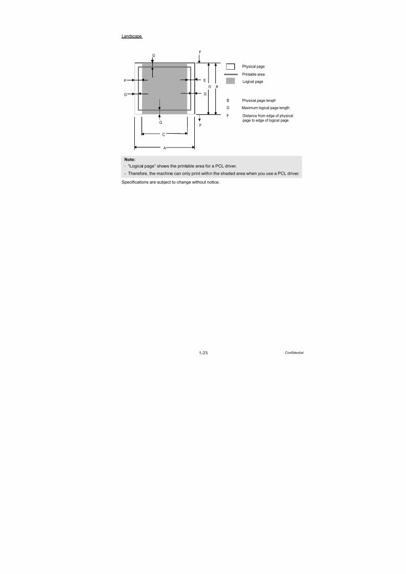
Specifications are subject to change without notice.
Note:
- “Logical page” shows the printable area for a PCL driver.
- Therefore, the machine can only print within the shaded area when you use a PCL driver.
Landscape
A
B
C
D
E
F
GF
G
E
G G
Physical page
Printable area
Logical page
B Physical page length
D Maximum logical page length
F Distance from edge of physical page to edge of logical page

7/18/2019 Brother Mfc 9125cn 9325cw en 5694 Mfp Sm
http://slidepdf.com/reader/full/brother-mfc-9125cn-9325cw-en-5694-mfp-sm 36/597
1-24 Confidential
The table below shows the printable areas when printing on Landscape for each paper size.
Specifications are subject to change without notice.
Size A B C D E F G
Letter (mm)(inch)(dots)
279.411
3,300
215.98.5
2,550
269.210.6
3,180
215.98.5
2,550
5.080.260
000
4.230.17
50
Legal
(mm)(inch)(dots)
355.614
4,200
215.98.5
2,550
345.413.6
4,080
215.98.5
2,550
5.080.260
000
4.230.17
50
Folio(mm)(inch)(dots)
330.213
3,900
215.98.5
2,550
32012.6
3,780
215.98.5
2,550
5.080.260
000
4.230.17
50
Executive(mm)(inch)(dots)
266.710.5
3,150
184.27.25
2,175
256.510.1
3,030
184.27.25
2,175
5.080.260
000
4.230.17
50
A4(mm)(inch)(dots)
29711.7
3,507
2108.3
2,480
28711.3
3,389
2108.3
2,480
50.259
000
4.230.17
50
A5(mm)(inch)(dots)
2108.3
2,480
1485.8
1,748
2007.9
2,362
1485.8
1,748
50.259
000
4.230.17
50
A5 Long Edge(mm)(inch)(dots)
1485.8
1,748
2108.3
2,480
1385.4
1,630
2108.3
2,480
50.259
000
4.230.17
50
A6(mm)(inch)(dots)
1485.8
1,748
1054.1
1,240
1385.4
1,630
1054.1
1,240
50.259
000
4.230.17
50
B5 (JIS)(mm)(inch)(dots)
25710.1
3,030
1827.2
2,148
2479.7
2,912
1827.2
2,148
50.259
000
4.230.17
50
B5 (ISO)(mm)(inch)(dots)
2509.8
2,952
1766.9
2,078
2409.4
2,834
1766.9
2,078
50.259
000
4.230.17
50
B6 (JIS)(mm)(inch)(dots)
1827.2
2,149
1285
1,511
1726.8
2,031
1285
1,511
50.259
000
4.230.17
50
B6 (ISO)(mm)(inch)(dots)
1766.9
2,078
1254.9
1,476
1666.5
1,960
1254.9
1,476
50.259
000
4.230.17
50
Envelope
Monarch
(mm)(inch)(dots)
190.57.5
2,250
98.43.8751,162
180.37.1
2,130
98.43.8751,162
5.080.260
000
4.230.17
50
Envelope
Com-10
(mm)(inch)(dots)
241.39.5
2,850
104.74.1251,237
231.19.1
2,730
104.74.1251,237
5.080.260
000
4.230.17
50
Envelope DL(mm)(inch)(dots)
2208.7
2,598
1104.3
1,299
2108.3
2,480
1104.3
1,299
50.259
000
4.230.17
50
Envelope C5(mm)(inch)(dots)
2299
2,704
1626.4
1,913
2198.6
2,586
1626.4
1,913
50.259
000
4.230.17
50
Hagaki(mm)(inch)(dots)
1485.8
1,748
1003.9
1,181
1385.4
1,630
1003.9
1,181
50.259
000
4.230.17
50
A4 Long(mm)(inch)(dots)
40515.9
4,783
2108.3
2,480
39515.6
4,665
2108.3
2,480
50.259
000
4.230.17
50
DL LongEdge
(mm)(inch)(dots)
1104.3
1,299
2208.7
2,598
1024
1,199
2208.7
2,598
4.230.17
50
000
6.270.25
74
3X5(mm)(inch)(dots)
1275
1,500
76.23
900
116.84.6
1,380
76.23
900
5.080.260
000
4.230.17
50
Note:
- The paper sizes indicated here should confirm to the nominal dimensions specified by JIS
except B5 (ISO), B6 (ISO).
- The dot size is based on 300 dpi resolution.
7/18/2019 Brother Mfc 9125cn 9325cw en 5694 Mfp Sm
http://slidepdf.com/reader/full/brother-mfc-9125cn-9325cw-en-5694-mfp-sm 37/597
1-25 Confidential
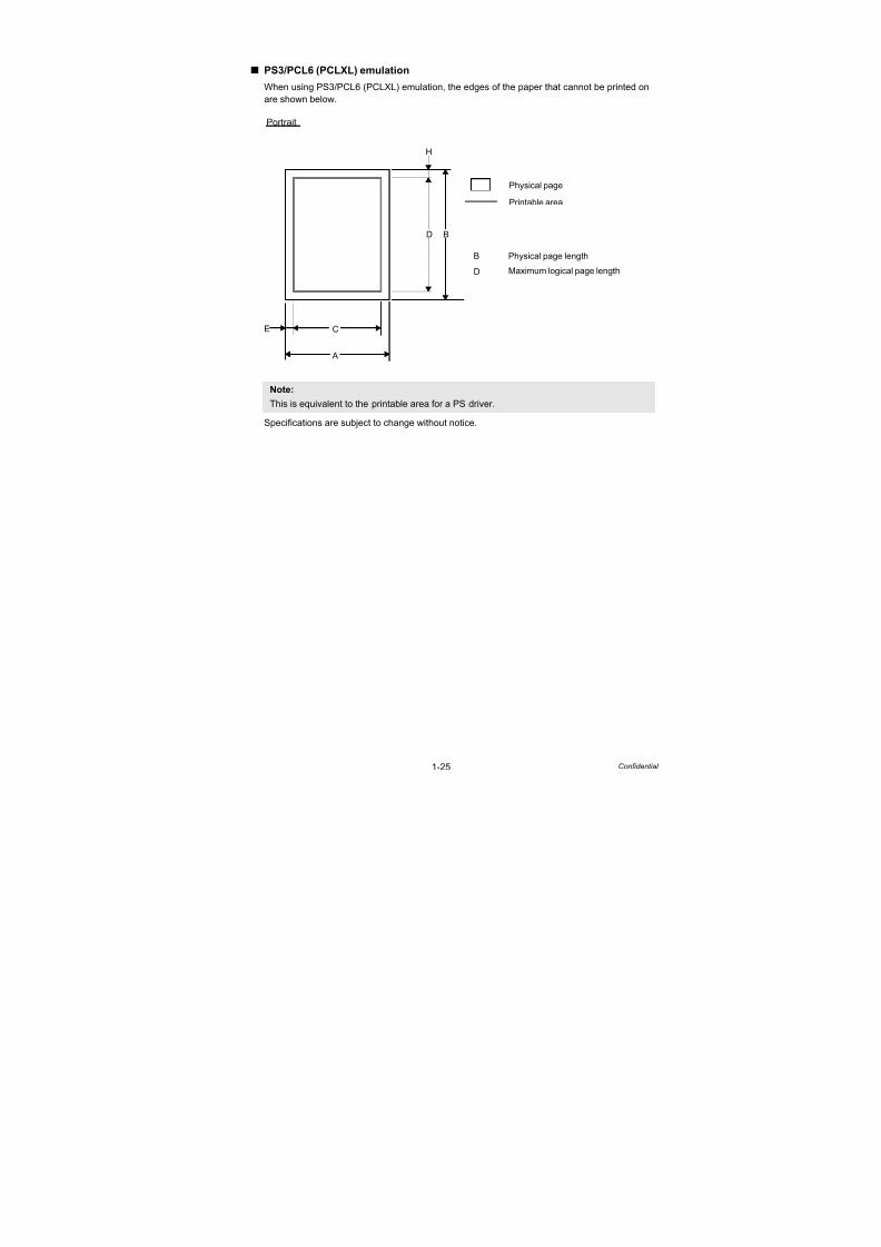
PS3/PCL6 (PCLXL) emulation
When using PS3/PCL6 (PCLXL) emulation, the edges of the paper that cannot be printed on
are shown below.
Specifications are subject to change without notice.
Note:
This is equivalent to the printable area for a PS driver.
Portrait
A
B
C
D
E
H
Physical page
Printable area
B Physical page length
D Maximum logical page length
7/18/2019 Brother Mfc 9125cn 9325cw en 5694 Mfp Sm
http://slidepdf.com/reader/full/brother-mfc-9125cn-9325cw-en-5694-mfp-sm 38/597
1-26 Confidential
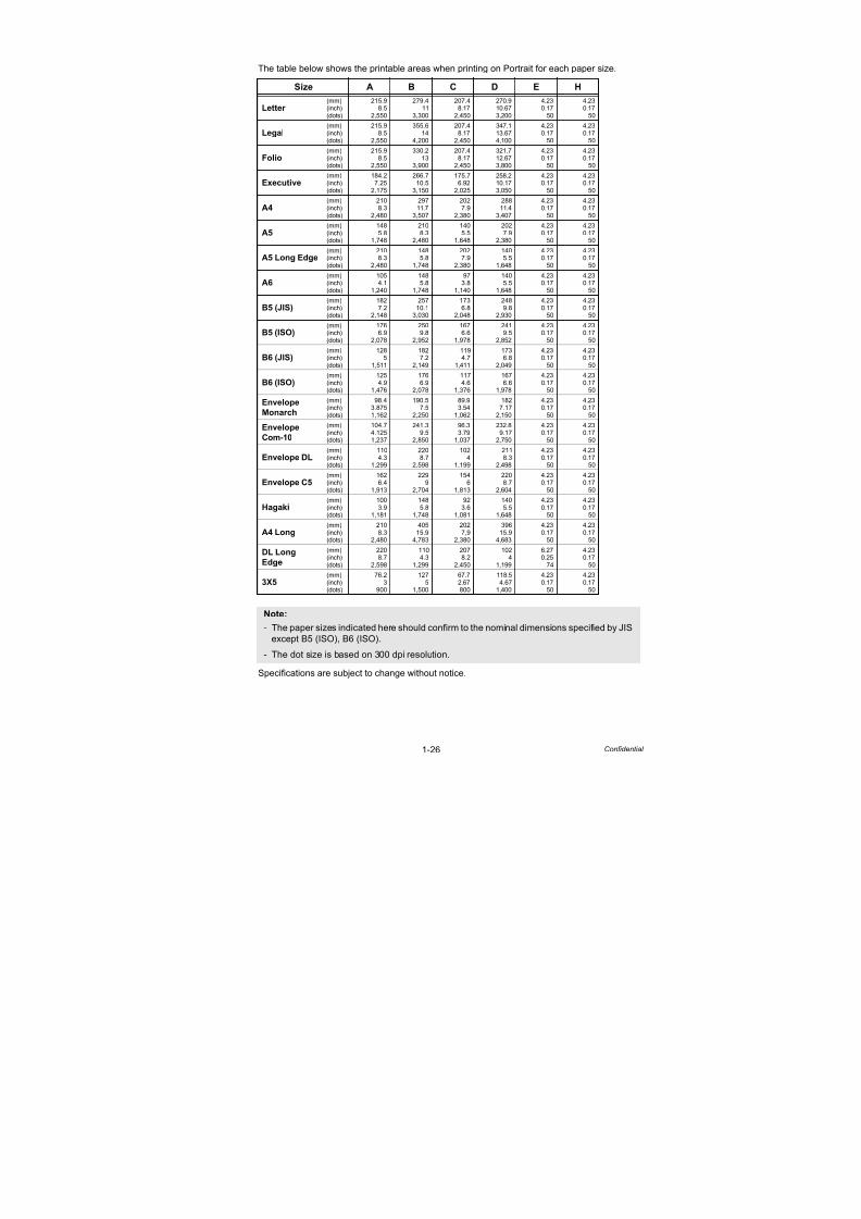
The table below shows the printable areas when printing on Portrait for each paper size.
Specifications are subject to change without notice.
Size A B C D E H
Letter (mm)(inch)(dots)
215.98.5
2,550
279.411
3,300
207.48.17
2,450
270.910.673,200
4.230.17
50
4.230.17
50
Legal
(mm)(inch)(dots)
215.98.5
2,550
355.614
4,200
207.48.17
2,450
347.113.674,100
4.230.17
50
4.230.17
50
Folio(mm)(inch)(dots)
215.98.5
2,550
330.213
3,900
207.48.17
2,450
321.712.673,800
4.230.17
50
4.230.17
50
Executive(mm)(inch)(dots)
184.27.25
2,175
266.710.5
3,150
175.76.92
2,025
258.210.173,050
4.230.17
50
4.230.17
50
A4(mm)(inch)(dots)
2108.3
2,480
29711.7
3,507
2027.9
2,380
28811.4
3,407
4.230.17
50
4.230.17
50
A5(mm)(inch)(dots)
1485.8
1,748
2108.3
2,480
1405.5
1,648
2027.9
2,380
4.230.17
50
4.230.17
50
A5 Long Edge(mm)(inch)(dots)
2108.3
2,480
1485.8
1,748
2027.9
2,380
1405.5
1,648
4.230.17
50
4.230.17
50
A6(mm)(inch)(dots)
1054.1
1,240
1485.8
1,748
973.8
1,140
1405.5
1,648
4.230.17
50
4.230.17
50
B5 (JIS)(mm)(inch)(dots)
1827.2
2,148
25710.1
3,030
1736.8
2,048
2489.8
2,930
4.230.17
50
4.230.17
50
B5 (ISO)(mm)(inch)(dots)
1766.9
2,078
2509.8
2,952
1676.6
1,978
2419.5
2,852
4.230.17
50
4.230.17
50
B6 (JIS)(mm)(inch)(dots)
1285
1,511
1827.2
2,149
1194.7
1,411
1736.8
2,049
4.230.17
50
4.230.17
50
B6 (ISO)(mm)(inch)(dots)
1254.9
1,476
1766.9
2,078
1174.6
1,376
1676.6
1,978
4.230.17
50
4.230.17
50
Envelope
Monarch
(mm)(inch)(dots)
98.43.8751,162
190.57.5
2,250
89.93.54
1,062
1827.17
2,150
4.230.17
50
4.230.17
50
Envelope
Com-10
(mm)(inch)(dots)
104.74.1251,237
241.39.5
2,850
96.33.79
1,037
232.89.17
2,750
4.230.17
50
4.230.17
50
Envelope DL(mm)(inch)(dots)
1104.3
1,299
2208.7
2,598
1024
1,199
2118.3
2,498
4.230.17
50
4.230.17
50
Envelope C5(mm)(inch)(dots)
1626.4
1,913
2299
2,704
1546
1,813
2208.7
2,604
4.230.17
50
4.230.17
50
Hagaki(mm)(inch)(dots)
1003.9
1,181
1485.8
1,748
923.6
1,081
1405.5
1,648
4.230.17
50
4.230.17
50
A4 Long(mm)(inch)(dots)
2108.3
2,480
40515.9
4,783
2027,9
2,380
39615.9
4,683
4.230.17
50
4.230.17
50
DL LongEdge
(mm)(inch)(dots)
2208.7
2,598
1104.3
1,299
2078.2
2,450
1024
1,199
6.270.25
74
4.230.17
50
3X5(mm)(inch)(dots)
76.23
900
1275
1,500
67.72.67800
118.54.67
1,400
4.230.17
50
4.230.17
50
Note:
- The paper sizes indicated here should confirm to the nominal dimensions specified by JIS
except B5 (ISO), B6 (ISO).
- The dot size is based on 300 dpi resolution.
7/18/2019 Brother Mfc 9125cn 9325cw en 5694 Mfp Sm
http://slidepdf.com/reader/full/brother-mfc-9125cn-9325cw-en-5694-mfp-sm 39/597
1-27 Confidential
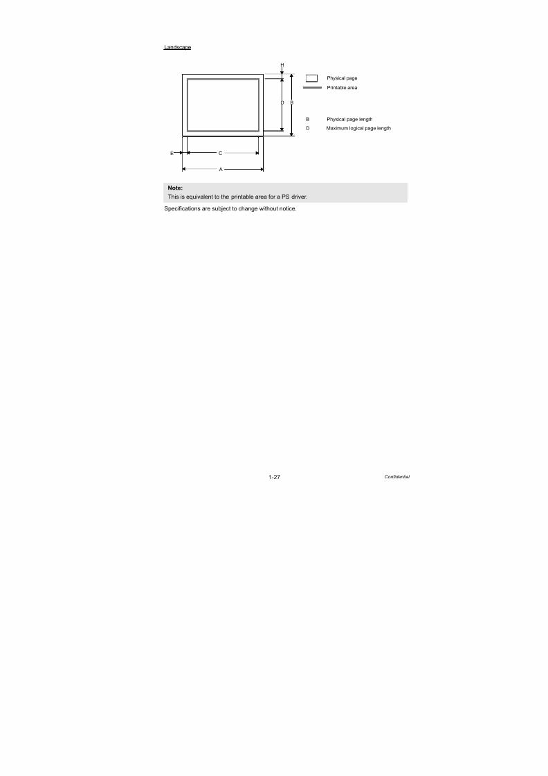
Specifications are subject to change without notice.
Note:
This is equivalent to the printable area for a PS driver.
Landscape
A
B
C
D
H
E
Physical page
Printable area
B Physical page length
D Maximum logical page length

7/18/2019 Brother Mfc 9125cn 9325cw en 5694 Mfp Sm
http://slidepdf.com/reader/full/brother-mfc-9125cn-9325cw-en-5694-mfp-sm 40/597
1-28 Confidential
The table below shows the printable areas when printing on Landscape for each paper size.
Specifications are subject to change without notice.
Size A B C D E H
Letter (mm)(inch)(dots)
279.411
3,300
215.98.5
2,550
270.910.673,200
207.48.17
2,450
4.230.17
50
4.230.17
50
Legal
(mm)(inch)(dots)
355.614
4,200
215.98.5
2,550
347.113.674,100
207.48.17
2,450
4.230.17
50
4.230.17
50
Folio(mm)(inch)(dots)
330.213
3,900
215.98.5
2,550
321.712.673,800
207.48.17
2,450
4.230.17
50
4.230.17
50
Executive(mm)(inch)(dots)
266.710.5
3,150
184.27.25
2,175
258.210.173,050
175.76.92
2,075
4.230.17
50
4.230.17
50
A4(mm)(inch)(dots)
29711.7
3,507
2108.3
2,480
28811.4
3,407
2027.9
2,380
4.230.17
50
4.230.17
50
A5(mm)(inch)(dots)
2108.3
2,480
1485.8
1,748
2027.9
2,380
1405.5
1,648
4.230.17
50
4.230.17
50
A5 Long Edge(mm)(inch)(dots)
1485.8
1,748
2108.3
2,480
1405.5
1,648
2027.9
2,380
4.230.17
50
4.230.17
50
A6(mm)(inch)(dots)
1485.8
1,748
1054.1
1,240
1405.5
1,648
973.8
1,140
4.230.17
50
4.230.17
50
B5 (JIS)(mm)(inch)(dots)
25710.1
3,030
1827.2
2,148
2489.8
2,930
1736.8
2,048
4.230.17
50
4.230.17
50
B5 (ISO)(mm)(inch)(dots)
2509.8
2,952
1766.9
2,078
2419.5
2,852
1676.6
1,978
4.230.17
50
4.230.17
50
B6 (JIS)(mm)(inch)(dots)
1827.2
2,149
1285
1,511
1736.8
2,049
1194.7
1,411
4.230.17
50
4.230.17
50
B6 (ISO)(mm)(inch)(dots)
1766.9
2,078
1254.9
1,476
1676.6
1,978
1174.6
1,376
4.230.17
50
4.230.17
50
Envelope
Monarch
(mm)(inch)(dots)
190.57.5
2,250
98.43.8751,162
1827.17
2,150
89.93.54
1,062
4.230.17
50
4.230.17
50
Envelope
Com-10
(mm)(inch)(dots)
241.39.5
2,850
104.74,1251,237
232.89.17
2,750
96.33.79
1,137
4.230.17
50
4.230.17
50
Envelope DL(mm)(inch)(dots)
2208.7
2,598
1104.3
1,299
2118.3
2,498
1024
1,199
4.230.17
50
4.230.17
50
Envelope C5(mm)(inch)(dots)
2299
2,704
1626.4
1,913
2208.7
2,604
1546
1,813
4.230.17
50
4.230.17
50
Hagaki(mm)(inch)(dots)
1485.8
1,748
1003.9
1,181
1405.5
1,648
923.6
1,081
4.230.17
50
4.230.17
50
A4 Long(mm)(inch)(dots)
40515.9
4,783
2108.3
2,480
39615.6
4,683
2027.9
2,380
4.230.17
50
4.230.17
50
DL LongEdge
(mm)(inch)(dots)
1104.3
1,299
2208.7
2,598
1024
1,199
2078.2
2,450
4.230.17
50
6.270.25
74
3X5(mm)(inch)(dots)
1275
1,500
76.23
900
118.54.67
1,400
67.72.67800
4.230.17
50
4.230.17
50
Note:
- The paper sizes indicated here should confirm to the nominal dimensions specified by JIS
except B5 (ISO), B6 (ISO).
- The dot size is based on 300 dpi resolution.

7/18/2019 Brother Mfc 9125cn 9325cw en 5694 Mfp Sm
http://slidepdf.com/reader/full/brother-mfc-9125cn-9325cw-en-5694-mfp-sm 41/597
1-29 Confidential
2.7 Print Speeds with Various Settings
Print speed is up to 18 ppm for A4 size and 19 ppm for Letter size when loading A4 or Letter
size paper from the paper tray in the plain paper mode.
Actual print speed varies depending on the media type or paper size as shown in the tables
below:
<A4/Letter size>
<Smaller size than A4 or Letter>
Specifications are subject to change without notice.
Media type setting Print speed
Plain paper,
Recycled paper
DCP9010CN/MFC9010CN/MFC9120CN/MFC9320CW: 16/17 ppm
MFC9125CN/MFC9325CW: 18/19 ppm
Thick paper,
Envelope,
Envelope thin, Label
8 ppm
Thicker paper,Bond paper,
Envelope thick
4 ppm
Media type setting Print speed
Plain paper,
Recycled paper
DCP9010CN/MFC9010CN/MFC9120CN/MFC9320CW: 17 ppm
MFC9125CN/MFC9325CW: 19 ppm
Thick paper,
Envelope,
Envelope thin, Label
8 ppm
Thicker paper,
Bond paper,
Envelope thick
4 ppm
Note:
The actual print speed may vary according to conditions, such as paper size and paper tray.
7/18/2019 Brother Mfc 9125cn 9325cw en 5694 Mfp Sm
http://slidepdf.com/reader/full/brother-mfc-9125cn-9325cw-en-5694-mfp-sm 42/597
1-30 Confidential
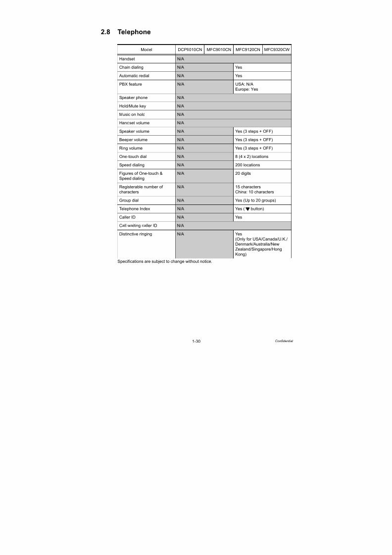
2.8 Telephone
Specifications are subject to change without notice.
Model DCP9010CN MFC9010CN MFC9120CN MFC9320CW
Handset N/A
Chain dialing N/A Yes
Automatic redial N/A Yes
PBX feature N/A USA: N/A
Europe: Yes
Speaker phone N/A
Hold/Mute key N/A
Music on hold N/A
Handset volume N/ASpeaker volume N/A Yes (3 steps + OFF)
Beeper volume N/A Yes (3 steps + OFF)
Ring volume N/A Yes (3 steps + OFF)
One-touch dial N/A 8 (4 x 2) locations
Speed dialing N/A 200 locations
Figures of One-touch &
Speed dialing
N/A 20 digits
Registerable number ofcharacters
N/A 15 charactersChina: 10 characters
Group dial N/A Yes (Up to 20 groups)
Telephone Index N/A Yes ( button)
Caller ID N/A Yes
Call waiting caller ID N/A
Distinctive ringing N/A Yes
(Only for USA/Canada/U.K./
Denmark/Australia/New
Zealand/Singapore/HongKong)

7/18/2019 Brother Mfc 9125cn 9325cw en 5694 Mfp Sm
http://slidepdf.com/reader/full/brother-mfc-9125cn-9325cw-en-5694-mfp-sm 43/597
1-31 Confidential
Specifications are subject to change without notice.
Model MFC9125CN MFC9325CW
Handset N/A
Chain dialing Yes
Automatic redial Yes
PBX feature N/A
Speaker phone N/A
Hold/Mute key N/A
Music on hold N/A
Handset volume N/A
Speaker volume Yes (3 steps + OFF)
Beeper volume Yes (3 steps + OFF)
Ring volume Yes (3 steps + OFF)
One-touch dial 8 (4 x 2) locations
Speed dialing 200 locations
Figures of One-touch &
Speed dialing
20 digits
Registerable number of
characters
15 characters
Group dial Yes (Up to 20 groups)
Telephone Index Yes ( button)
Caller ID Yes
Call waiting caller ID N/A
Distinctive ringing Yes

7/18/2019 Brother Mfc 9125cn 9325cw en 5694 Mfp Sm
http://slidepdf.com/reader/full/brother-mfc-9125cn-9325cw-en-5694-mfp-sm 44/597
1-32 Confidential
2.9 FAX
*1 Not available for Color Fax
Specifications are subject to change without notice.
Model DCP9010CN MFC9010CN MFC9120CN MFC9320CW
Modem speed N/A 33,600 bps (Fax)
Transmission speed N/A Approximately 2 seconds
(Brother#1 Std resolution,
JBIG)
ITU-T group N/A Super G3
Coding method N/A MH/MR/MMR/JBIG/JPEG
Color FAX Sending N/A Yes (Not available for saving
the data into the Memory)
Receiving N/A Yes (Not available for saving
the data into the Memory)
Fax/Tel switch N/A YesSuperfine N/A Yes (TX & RX)
Grayscale N/A 8 bit/256
Contrast N/A Yes (Auto/Light/Dark)
Smoothing N/A
Dual access*1 N/A Yes
Remote activate N/A Yes
Station ID N/A Yes (20 digits/20 characters)
Remote maintenance N/A
Remote access N/A Yes
FAX retrieval N/A Yes
Paging*1 N/A USA/Canada: Yes
Europe: N/A
Internet FAX
(ITU T.37 simple mode)
N/A Yes (Download only)
Sending Delayed
timer *1N/A Yes (up to 50)
Polled
sending*1
N/A Yes (EUR Secure Polling)
Multi
transmission
N/A
Multi
Resolution
transmission
N/A
Next-Fax
reservation
N/A
Batch
transmission*1N/A Yes

7/18/2019 Brother Mfc 9125cn 9325cw en 5694 Mfp Sm
http://slidepdf.com/reader/full/brother-mfc-9125cn-9325cw-en-5694-mfp-sm 45/597
1-33 Confidential
*2
Not available for Color Fax
Specifications are subject to change without notice.
Model DCP9010CN MFC9010CN MFC9120CN MFC9320CW
Sending Call
reservation
(Auto)
N/A
Callreservation
(Manual TX)
N/A
Quick scan*2
(Memory
transmission)
N/A Approximately 2.5 seconds/
page (A4standard)
Memory
transmission*2
(ITU-T Chart)
N/A up to 500 pages (ITU-T Test
Chart#1, Standard Resolution,
JBIG)
up to 600 pages (Brother #1
Chart, Standard Resolution,
JBIG)
ECM N/A Yes
Error
Re-Transmis-
sion *2
N/A Yes
Broadcasting*2
N/A Yes (258 locations)
Manual
broadcasting *2N/A Yes (50 locations)
Fax
forwarding *2N/A Yes
Fax
forwarding
broadcast *2
N/A Yes (207 locations)
Duplex Fax
sending*2N/A
Dial restriction N/A Yes
Receiving Easy receive/
Fax detect
N/A Yes
Polling receive N/A Yes (EUR Secure Polling)
Auto reduction N/A Yes
Duplex Fax
receiving
N/A
Out of paper
reception
(ITU-T Chart)*2
N/A Up to 500 pages (ITU-T Test
Chart, Standard Resolution,
JBIG)
Up to 600 pages (Brother
#1Chart, Standard Resolution,
JBIG)
Fax Rx
stamp *2N/A Yes

7/18/2019 Brother Mfc 9125cn 9325cw en 5694 Mfp Sm
http://slidepdf.com/reader/full/brother-mfc-9125cn-9325cw-en-5694-mfp-sm 46/597
1-34 Confidential
*3 Not available for Color Fax
Specifications are subject to change without notice.
Model MFC9125CN MFC9325CW
Modem speed 33,600 bps (Fax)
Transmission speed Approximately 2 seconds (Brother#1 Std resolution, JBIG)
ITU-T group Super G3Coding method MH/MR/MMR/JBIG/JPEG
Color FAX Sending Yes (Not available for saving the data into the Memory)
Receiving Yes (Not available for saving the data into the Memory)
Fax/Tel switch Yes
Superfine Yes (TX & RX)
Grayscale 8 bit/256
Contrast Yes (Auto/Light/Dark)
Smoothing N/A
Dual access*3 Yes
Remote activate Yes
Station ID Yes (20 digits/20 characters)
Remote maintenance N/A
Remote access Yes
FAX retrieval Yes
Paging*3 USA/Canada: Yes
Australia/New Zealand: N/A
Internet FAX(ITU T.37 simple mode)
Yes (Download only)
Sending Delayed
timer *3Yes (up to 50)
Polled
sending*3Yes (EUR Secure Polling)
Multi
transmission
N/A
Multi
Resolution
transmission
N/A
Next-Fax
reservation
N/A
Batch
transmission*3Yes

7/18/2019 Brother Mfc 9125cn 9325cw en 5694 Mfp Sm
http://slidepdf.com/reader/full/brother-mfc-9125cn-9325cw-en-5694-mfp-sm 47/597
1-35 Confidential
*4 Not available for Color Fax
Specifications are subject to change without notice.
Model MFC9125CN MFC9325CW
Sending Call
reservation
(Auto)
N/A
Callreservation
(Manual TX)
N/A
Quick scan*4
(Memory
transmission)
Approximately 2.5 seconds/page (A4standard)
Memory
transmission*4
(ITU-T Chart)
up to 500 pages (ITU-T Test Chart#1, Standard Resolution,
JBIG)
up to 600 pages (Brother #1 Chart, Standard Resolution, JBIG)
ECM Yes
Error
Re-Transmis-sion *4
Yes
Broadcasting*4
Yes (258 locations)
Manual
broadcasting *4Yes (50 locations)
Fax
forwarding *4Yes
Fax
forwarding
broadcast *4
Yes (207 locations)
Duplex Fax
sending*4N/A
Dial restriction Yes
Receiving Easy receive/
Fax detect
Yes
Polling receive Yes (EUR Secure Polling)
Auto reduction Yes
Duplex Fax
receiving
N/A
Out of paperreception
(ITU-T Chart)*4
Up to 500 pages (ITU-T Test Chart, Standard Resolution, JBIG)Up to 600 pages (Brother #1Chart, Standard Resolution, JBIG)
Fax Rx
stamp *4Yes

7/18/2019 Brother Mfc 9125cn 9325cw en 5694 Mfp Sm
http://slidepdf.com/reader/full/brother-mfc-9125cn-9325cw-en-5694-mfp-sm 48/597
1-36 Confidential
2.10 List/Report
*1 Not available for Color Fax
Specifications are subject to change without notice.
Model DCP9010CN MFC9010CN MFC9120CN MFC9320CW
Activity report/Journal report N/A Yes (Up to 200)
Transmission verification
report
N/A Yes
Coverpage*1 N/A Yes (Super)
Help list N/A Yes
Call back message N/A
Caller ID list N/A Yes
Tel Index list Numeric N/A Yes
Alphabetic N/A Yes
Memory status list N/A
System setup (User setting)
list
Yes
Model MFC9125CN MFC9325CW
Activity report/Journal report Yes (Up to 200)
Transmission verification
report
Yes
Coverpage*1 Yes (Super)
Help list Yes
Call back message N/A
Caller ID list Yes
Tel Index list Numeric Yes
Alphabetic Yes
Memory status list N/A
System setup (User setting)list
Yes

7/18/2019 Brother Mfc 9125cn 9325cw en 5694 Mfp Sm
http://slidepdf.com/reader/full/brother-mfc-9125cn-9325cw-en-5694-mfp-sm 49/597
1-37 Confidential
2.11 Copy
*1 The time may change if the machine is calibrating or registering itself.
Specifications are subject to change without notice.
Model DCP9010CN MFC9010CN MFC9120CN MFC9320CW
Copy speed
simplex
Monochrome Up to 16 cpm (A4 size)
Up to 17 cpm (Letter size)Color
First copy
out time
(from ready
mode)
Monochrome Less than 19 seconds *1
Color Less than 24 seconds *1
Multi copy Stack Yes (Up to 99)
Sort Yes
Reduction/Enlargement (%) 25 % - 400 % in 1 % increments
Resolution (dpi) Maximum. 600 (main scanning) x 600 (sub scanning) dpi
Auto duplex copy N/A
Manual duplex copy N/A
N in 1 Yes
Poster N/A
Image enhancement N/A
Model MFC9125CN MFC9325CW
Copy speed
simplex
Monochrome Up to 18 cpm (A4 size)
Up to 19 cpm (Letter size)Color
First copy
out time
(from ready
mode)
Monochrome Less than 19 seconds *1
Color Less than 24 seconds *1
Multi copy Stack Yes (Up to 99)
Sort Yes
Reduction/Enlargement (%) 25 % - 400 % in 1 % increments
Resolution (dpi) Maximum. 600 (main scanning) x 600 (sub scanning) dpi
Auto duplex copy N/A
Manual duplex copy N/A
N in 1 Yes
Poster N/A
Image enhancement N/A

7/18/2019 Brother Mfc 9125cn 9325cw en 5694 Mfp Sm
http://slidepdf.com/reader/full/brother-mfc-9125cn-9325cw-en-5694-mfp-sm 50/597
1-38 Confidential
2.12 Scanner
*1 Time to scan Letter/A4 sheet at 300 dpi. The time may vary depending on the document
type and other conditions. Data transmission time is not included.
*2 Supported file formats are PDF/secure PDF version 1.3, JPEG, XPS version 1.0 for color
and gray, TIFF for B&W scan.
Specifications are subject to change without notice.
Model DCP9010CN MFC9010CN MFC9120CN MFC9320CW
Color/Monochrome Color
Resolution
(Optical)
FB Maximum scanning 1,200 (main scanning) x 2,400 dpi (sub
scanning)
ADF Maximum scanning 1,200 (main scanning) x 600 dpi (sub
scanning)
Resolution (Interpolated) 19,200 (main scanning) x 19,200 (sub scanning) dpi
Scanning
speed
Monochrome 2.35 (Letter)/2.49 (A4) seconds*1
Color 7.04 (Letter)/7.48 (A4) seconds*1
Grayscale 256 level
Color depth (Int./Ext.) 48 bit/24 bit
Custom scan profile N/A Yes
Duplex scanning N/A
Scan to E-mail Yes
Scant to E-mail server
(I-Fax)*2N/A Yes (It provides only from the
Web site)
Scan to image Yes
Scan to OCR Yes
Scan to file Yes
Scan to FTP*2 N/A Yes
Scan to USB*2 N/A Yes
Scan to network*2 N/A Yes

7/18/2019 Brother Mfc 9125cn 9325cw en 5694 Mfp Sm
http://slidepdf.com/reader/full/brother-mfc-9125cn-9325cw-en-5694-mfp-sm 51/597
1-39 Confidential
*3 Time to scan Letter/A4 sheet at 300 dpi. The time may vary depending on the document
type and other conditions. Data transmission time is not included.
*4 Supported file formats are PDF/secure PDF version 1.3, JPEG, XPS version 1.0 for color
and gray, TIFF for B&W scan.
Specifications are subject to change without notice.
Model MFC9125CN MFC9325CW
Color/Monochrome Color
Resolution
(Optical)
FB Maximum scanning 1,200 (main scanning) x 2,400 dpi (sub
scanning)
ADF Maximum scanning 1,200 (main scanning) x 600 dpi (sub
scanning)
Resolution (Interpolated) 19,200 (main scanning) x 19,200 (sub scanning) dpi
Scanning
speed
Monochrome 2.35 (Letter)/2.49 (A4) seconds*3
Color 7.04 (Letter)/7.48 (A4) seconds*3
Grayscale 256 level
Color depth (Int./Ext.) 48 bit/24 bit
Custom scan profile Yes
Duplex scanning N/A
Scan to E-mail Yes
Scant to E-mail server
(I-Fax)*4Yes (It provides only from the Web site)
Scan to image Yes
Scan to OCR Yes
Scan to file Yes
Scan to FTP*4 Yes
Scan to USB*4 N/A Yes
Scan to network*4 Yes

7/18/2019 Brother Mfc 9125cn 9325cw en 5694 Mfp Sm
http://slidepdf.com/reader/full/brother-mfc-9125cn-9325cw-en-5694-mfp-sm 52/597
1-40 Confidential
2.13 USB Direct Interface
Specifications are subject to change without notice.
Model DCP9010CN MFC9010CN MFC9120CN MFC9320CW
PictBridge N/A Yes
Direct print N/A PDF version
1.7, JPEG,
Exif+JPEG,
PRN (created
by own printer
driver), TIFF
(scanned by
Brother
model), XPS
version 1.0
Media drive N/A
Model MFC9125CN MFC9325CW
PictBridge N/A Yes
Direct print N/A PDF version 1.7,
JPEG, Exif+JPEG, PRN
(created by own printer
driver), TIFF
(scanned by Brother model),
XPS version 1.0
Media drive N/A

7/18/2019 Brother Mfc 9125cn 9325cw en 5694 Mfp Sm
http://slidepdf.com/reader/full/brother-mfc-9125cn-9325cw-en-5694-mfp-sm 53/597
Confidential
CHAPTER 2THEORY OF OPERATION

7/18/2019 Brother Mfc 9125cn 9325cw en 5694 Mfp Sm
http://slidepdf.com/reader/full/brother-mfc-9125cn-9325cw-en-5694-mfp-sm 54/597
Confidential
CHAPTER 2
THEORY OF OPERATIONThis chapter gives an overview of the printing mechanisms as well as the sensors, actuators and
control electronics. It aids in understanding the basic principles of operation as well as locating defectsfor troubleshooting.
CONTENTS
1. GENERAL BLOCK DIAGRAM ..................................................................2-1
2. ELECTRONICS GENERAL BLOCK DIAGRAM........................................2-2
3. MECHANICS ..............................................................................................2-33.1 Cross-section Drawing ............................................................................................... 2-3
3.2 Scanner Mechanism................................................................................................... 2-5
3.2.1 Document scanner unit...................................................................................... 2-6
3.2.2 ADF unit............................................................................................................. 2-8
3.3 Paper Feeding.......................................................................................................... 2-10
3.3.1 Plate-up function of the paper tray .................................................................. 2-11
3.3.2 Paper supply.................................................................................................... 2-12
3.3.3 Paper registration ............................................................................................ 2-133.3.4 Paper eject ...................................................................................................... 2-14
3.3.5 Paper supply from manual feed slot and paper eject from back...................... 2-15
3.4 Toner Cartridge......................................................................................................... 2-16
3.4.1 Type of toner cartridge..................................................................................... 2-16
3.4.2 Life of toner cartridge....................................................................................... 2-16
3.4.3 Method of detecting toner life .......................................................................... 2-17
3.4.4 Relationship between toner amount and life of toner cartridge in number ofrotations of develop roller ................................................................................ 2-17
3.4.5 New toner detection......................................................................................... 2-19
3.4.6 Method of counting the number of toner replacements ................................... 2-21
3.5 Principle of Color Overlapping.................................................................................. 2-22
3.6 Basic Printing Principle............................................................................................. 2-23
3.6.1 Charging.......................................................................................................... 2-24
3.6.2 Exposure ......................................................................................................... 2-25
3.6.3 Development ................................................................................................... 2-26
3.6.4 Transfer ........................................................................................................... 2-27
3.6.5 Fusing.............................................................................................................. 2-28
3.6.6 Toner cleaning ................................................................................................. 2-29

7/18/2019 Brother Mfc 9125cn 9325cw en 5694 Mfp Sm
http://slidepdf.com/reader/full/brother-mfc-9125cn-9325cw-en-5694-mfp-sm 55/597
Confidential
3.7 Location of Sensors.................................................................................................. 2-30
3.8 Adjustment of Color Registration.............................................................................. 2-34
3.8.1 Color registration error in sub/main scanning direction ................................... 2-34
3.9 Adjustment of Color Density ..................................................................................... 2-34

7/18/2019 Brother Mfc 9125cn 9325cw en 5694 Mfp Sm
http://slidepdf.com/reader/full/brother-mfc-9125cn-9325cw-en-5694-mfp-sm 56/597
2-1 Confidential
1. GENERAL BLOCK DIAGRAM
Fig. 2-1
Develop drive motor
Develop releasemotor
Belt drive motor
Paper feed Fuser unit Paper eject tray
Paper feed motor
Drum drive motor
Paper tray
HVPS control block
HVPS block
Drum unit
Belt unit
Develop unit K Y M C
K Y M C
Paper feed system
Image forming system
Belt cleaner block
Toner
Developing block
Exposure drum
Cleaner block
Transfer block
Charging block
Toner
Developing block
Exposure drum
Cleaner block
Transfer block
Charging block
Toner
Developing block
Exposure drum
Cleaner block
Transfer block
Charging block
Toner
Developing block
Exposure drum
Cleaner block
Transfer block
Charging block
Belt cleaner
unit
Fuser/eject drivemotor
Operation block(Panel)
LED unit
USB device or Digital camera
InternalRAM
RAMDIMM144 pin
(Wired LAN)
(Wireless LAN module)
(Wireless LAN model)
(USB direct)(USB direct interface model)
(USB)
Video control system
Video control block
Low-voltagepower supply block
Interface
Interface
Interface
Interface
E x t e r n a l d e v i c e
Engine control block
Exposure system Engine control system
CIS unit
ADF sensor
Speaker
Battery(FAX model)
Telephonelines
NCU(FAX model)
ADF motor
FB motor
ADF driver
FB driver

7/18/2019 Brother Mfc 9125cn 9325cw en 5694 Mfp Sm
http://slidepdf.com/reader/full/brother-mfc-9125cn-9325cw-en-5694-mfp-sm 57/597
2-2 Confidential
2. ELECTRONICS GENERAL BLOCK DIAGRAM
Fig. 2-2
Engine PCB
Develop drive motor
Paper feed motor
Belt drive motor
Develop release motor
Drum drive motor
Pick-up solenoidRegistration solenoid
Toner/New sensor PCB
Drum motor origin sensor PCB
Internal temperature thermistor
(ExternalTHM/HUM
sensor)
Fuser unit
Fuser thermistor 1
Fuser thermistor 2
Eject front sensor PCB
Main PCB
USB direct interface relay PCB
(USB direct interface model)
NCU PCB (FAX model)
Btattery (FAX model)
Speaker
CIS
HVPScontrolPCB
LV fan
Main fan
Toner LED PCB (emission)
Waste toner sensor
Top cover open switch
Develop release sensor PCB
Registration front/rear sensor PCB
Manual sensor PCB
Panel PCB (Backlight)LCD
Low-voltage power supply PCB
Registration
mark relay
PCB
Belt thermistor
Registration mark L PCB
Registration mark R PCB
Density sensor shutter solenoid
Fuser/eject drive motor
LED head (K)
LED head (Y)
LED head (M)
LED head (C)
Eject rear sensor PCB
ADF sensor
HP sensor
ADF driver
FB driver
ADF motor
FB motor
LED head control PCB
Wireless LAN PCB (Wireless LAN model)
Back cover open switch
LED power relay PCB
High-voltagepower supplyPCB

7/18/2019 Brother Mfc 9125cn 9325cw en 5694 Mfp Sm
http://slidepdf.com/reader/full/brother-mfc-9125cn-9325cw-en-5694-mfp-sm 58/597
2-3
3. MECHANICS
3.1 Cross-section Drawing
Printer part
Fig. 2-3
Exit roller 2
Heat roller Belt unit
Waste toner box
Plate
Paper pick-up roller
Separation roller
Paper tray
Feed roller
Registration front actuator
Manual paper actuator
PF registration roller
Registration rear actuator
Supply roller
Cleaner shaft
Exposure drum (Y)
Separation pad ASSY
Exposure drum (M)Cleaner sponge
Exposure drum (K)
Develop roller
Exposure drum (C)
Pinch roller
Pinch roller 2Ex
<Front>
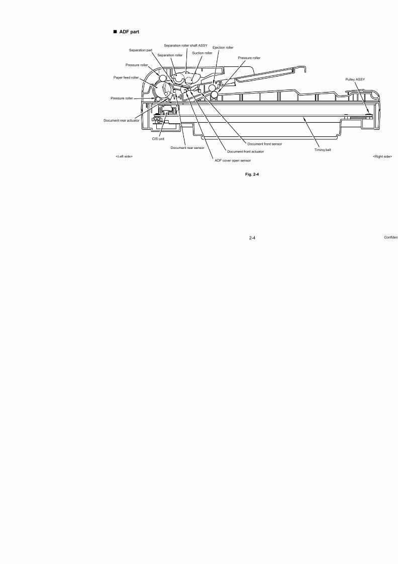
7/18/2019 Brother Mfc 9125cn 9325cw en 5694 Mfp Sm
http://slidepdf.com/reader/full/brother-mfc-9125cn-9325cw-en-5694-mfp-sm 59/597
2-4
ADF part
Fig. 2-4
Separation roller shaft ASSY
Pressure roller
Pressure roller
Document rear actuator
Document front actuator
Pressure roller
Ejection roller Separation pad
Separation roller
CIS unit
Document rear sensor Document front sensor
Timing b
ADF cover open sensor <Left side>
Suction roller
Paper feed roller

7/18/2019 Brother Mfc 9125cn 9325cw en 5694 Mfp Sm
http://slidepdf.com/reader/full/brother-mfc-9125cn-9325cw-en-5694-mfp-sm 60/597
2-5 Confidential
3.2 Scanner Mechanism
This mechanism consists of the document cover, the document scanner unit (scanner cover),
and the automatic document feeder (ADF).
The document scanner unit consists of a scanner top cover, CIS unit, CIS drive ASSY, and
scanner base.
Fig. 2-5
Document cover
ADF
ADF & Document cover ASSY
Scanner top cover
White-level reference film
CIS drive belt
CIS idle pulley
CIS rail
Scanner base
CIS drive ASSY
CIS flat cable
CIS unit
Document scanner unit(Scanner cover)
(CIS motor)

7/18/2019 Brother Mfc 9125cn 9325cw en 5694 Mfp Sm
http://slidepdf.com/reader/full/brother-mfc-9125cn-9325cw-en-5694-mfp-sm 61/597
2-6 Confidential
3.2.1 Document scanner unit
The document scanner unit is equipment which scans the paper using the CIS unit. This
machine prints the scanning data (copy) or data is sent by fax (fax transmission).
There are two kinds of scanning method of the document scanner unit. One is operation to
scan with the document scanner unit, the paper is placed on the document glass, the CIS unit
moves is the bottom of it, and it scans the paper, and other is operation to scan in connectionwith the ADF unit, scan the paper which has been sent over the immovable CIS unit.
(1) CIS unit
The CIS unit includes the contact image sensor (CIS) (Resolution of horizontal scanning:
Maximum1,200 dpi color scanning).
The light source is light-emitting-diode (LED) of the RGB. The RGB is changed at high
speed respectively, and lead the light from the document directly to the image pickup
device (CMOS image sensor) through the rod lens array, and the image is generated.
(2) Driving of the CIS unit
The CIS unit is supported by the CIS rail and assembled on the drive belt. When the CIS
motor is rotated counter clockwise, the CIS unit on the drive belt scans the documentwhile sliding to the right hand side. In this case, the CIS unit has the capacity to scan at
2,400 dpi resolution of sub scanning.
(3) The CIS unit home position detection (FB home position detection)
The CIS unit is configured at the FB home position to determine the scanning position of
the sub scanning direction.
Based on the scanning position, the FB home position is detected when the home
position sensor inside of the document scanner unit.
(4) White level compensation
Whenever the variation of the CIS unit, the correction of the time degradation and the
value of the white color scans, in order to make them not different.
The white level compensation keeps a fixed value of the white color by scanning the
white-level reference film inside the document scanner unit with the CIS unit.

7/18/2019 Brother Mfc 9125cn 9325cw en 5694 Mfp Sm
http://slidepdf.com/reader/full/brother-mfc-9125cn-9325cw-en-5694-mfp-sm 62/597
2-7 Confidential
(5) Scanning operation (The CIS unit moves under the immovable document.)
Open the document cover, place a sheet of the document (or opened book) onto the
document glass, and close the document cover. Then, the machine starts scanning by
the operation of the panel, and the CIS drive mechanism is started and the scanning
operation is started.
The motor is rotated so that its action is transferred to the drive belt through the gear train.
The CIS unit scans the document while sliding to the right hand side.
Fig. 2-6
ADF unit
Drive plate ASSY (Motor FB)
FFC cable
Document scanner unit
Pulley ASSY
CIS unit
CIS rail

7/18/2019 Brother Mfc 9125cn 9325cw en 5694 Mfp Sm
http://slidepdf.com/reader/full/brother-mfc-9125cn-9325cw-en-5694-mfp-sm 63/597
2-8 Confidential
3.2.2 ADF unit
The ADF unit is equipment which sends one document or the document for every plurality to
the ADF scanning part of the document scanner unit, and performs continuous scanning.
Performance of the ADF
- The number of maximum capacity: Up to 35 sheets
- Maximum resolution: Up to 1,200 (main scanning) x 600 (sub scanning) dpi
- Maximum scanning speed: 17 pages/minute (Letter size) 16 pages/minute (A4 size)
(Simplex scanning)
- Maximum input media size: Width 215.9 mm, Length 355.6 mm
- Minimum input media size: Width 147.3 mm, Length 147.3 mm
(1) Function of each roller
- Suction roller
Suction roller sends the inserted document to the inside of the ADF.- Separation roller
Separation roller separates the sent document one by one.
- Paper feed roller
Send the document.
- Ejection roller
Eject the document.
(2) Function of each sensor
- Document front sensor
Detects whether the document is set in the ADF.- Document rear sensor
Detect the timing of the scanning start of the document.
- ADF cover open sensor
Detects whether the ADF cover is opened or not. If the ADF cover is not closed,
scanning from the ADF will not start.
(3) Function of each motor
- ADF motor
Driving source of overall ADF.

7/18/2019 Brother Mfc 9125cn 9325cw en 5694 Mfp Sm
http://slidepdf.com/reader/full/brother-mfc-9125cn-9325cw-en-5694-mfp-sm 64/597
2-9 Confidential
(4) Internal structure
The automatic document feeder (ADF) consists of the separation roller shaft ASSY, paper
feed roller, ejection roller, ADF motor, document rear sensor, document front sensor and
ADF cover open sensor.
For further details on the sensors, refer to “3.7 Location of Sensors” in this chapter .
Fig. 2-7
In this reading system, “copyboard glass scanning” and “ADF scanning” are available.
These scanning types are switched based on whether or not the document front sensor
detects any document at the time when the scanning operation starts.
(5) ADF scanning (The document moves over the immovable CIS unit.)
1) Set the document face up into the document chute. When the machine starts simplex
scanning, the ADF motor is rotated clockwise, the suction roller draws the document,
and the separation roller and separation pad send a sheet of the document to the ADF
one by one from the top page of the stacked documents.
2) The document is passed through the paper feed roller, and is passed over the CIS
unit so that the document is scanned. Then, the document is ejected to the document
cover by the ejection roller.
Fig. 2-8
Pressure roller
Paper feed roller
Pressure roller
Document rear actuator Document front actuator
Pressure roller
Ejection roller Separation pad
Separation roller
Separation roller shaft ASSY
Document front sensor
ADF cover open sensor Document rear sensor
Suction roller
Separation roller shaft ASSY
Pressure roller
Paper feed roller
Pressure roller
Pressure roller
Document cover
Ejection roller
CIS unit
Separation pad
Separation roller
Suction roller
Paper feed chute ASSY

7/18/2019 Brother Mfc 9125cn 9325cw en 5694 Mfp Sm
http://slidepdf.com/reader/full/brother-mfc-9125cn-9325cw-en-5694-mfp-sm 65/597
2-10
3.3 Paper Feeding
Fig. 2-9
<Front>
Paper tray path
Manual feed slot path
Pape
(Ref
Manual feed
Plate-up function(Refer to “3.3.1”)
Paper pick-up
function(Refer to “3.3.5”)
function
(Refer to “3.3.2”)
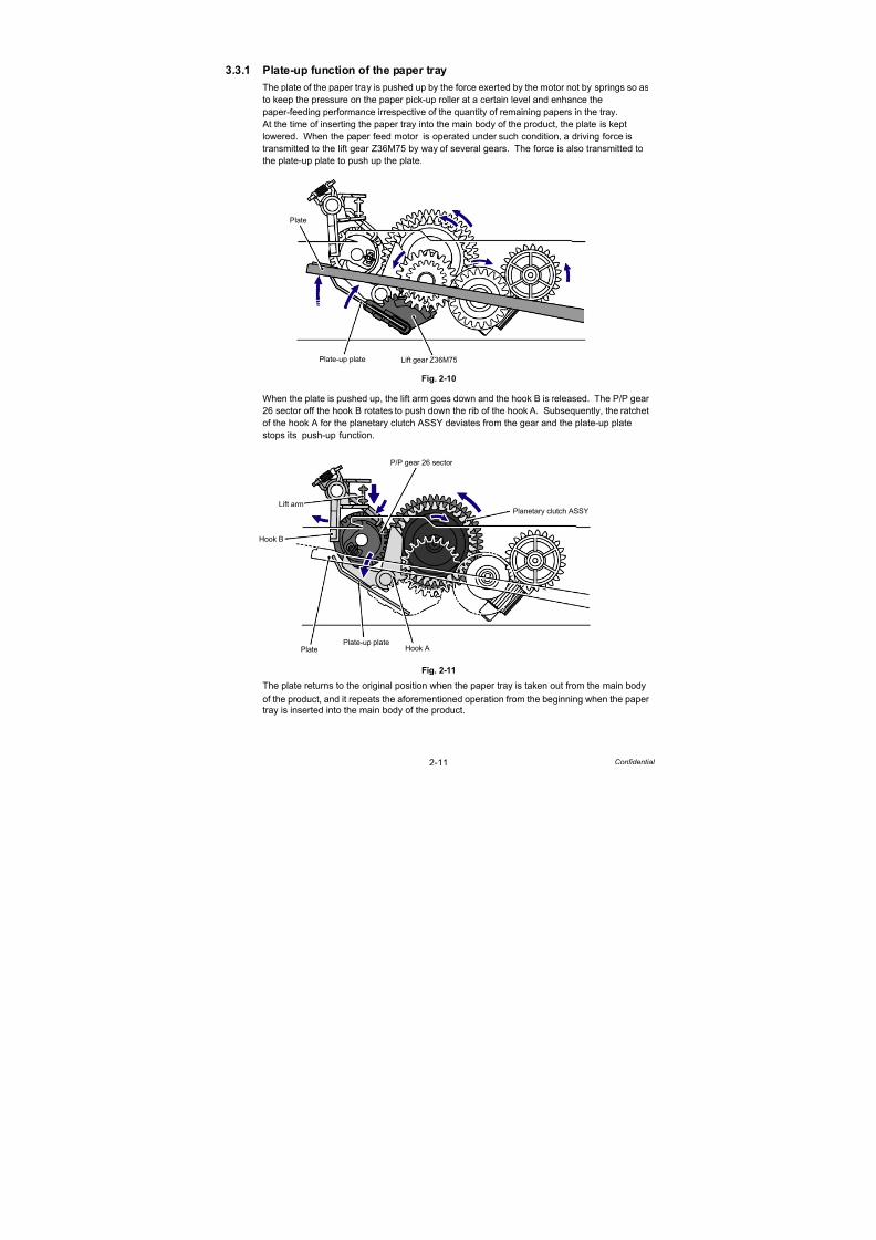
7/18/2019 Brother Mfc 9125cn 9325cw en 5694 Mfp Sm
http://slidepdf.com/reader/full/brother-mfc-9125cn-9325cw-en-5694-mfp-sm 66/597
2-11 Confidential
3.3.1 Plate-up function of the paper tray
The plate of the paper tray is pushed up by the force exerted by the motor not by springs so as
to keep the pressure on the paper pick-up roller at a certain level and enhance the
paper-feeding performance irrespective of the quantity of remaining papers in the tray.
At the time of inserting the paper tray into the main body of the product, the plate is kept
lowered. When the paper feed motor is operated under such condition, a driving force istransmitted to the lift gear Z36M75 by way of several gears. The force is also transmitted to
the plate-up plate to push up the plate.
Fig. 2-10
When the plate is pushed up, the lift arm goes down and the hook B is released. The P/P gear
26 sector off the hook B rotates to push down the rib of the hook A. Subsequently, the ratchet
of the hook A for the planetary clutch ASSY deviates from the gear and the plate-up plate
stops its push-up function.
Fig. 2-11
The plate returns to the original position when the paper tray is taken out from the main body
of the product, and it repeats the aforementioned operation from the beginning when the papertray is inserted into the main body of the product.
Plate
Plate-up plate Lift gear Z36M75
Hook B
Lift arm
P/P gear 26 sector
Hook APlate-up plate
Plate
Planetary clutch ASSY

7/18/2019 Brother Mfc 9125cn 9325cw en 5694 Mfp Sm
http://slidepdf.com/reader/full/brother-mfc-9125cn-9325cw-en-5694-mfp-sm 67/597
2-12 Confidential
3.3.2 Paper supply
When the paper pick-up solenoid is turned ON, the power of the paper feed motor rotates the
paper pick-up roller, and it picks up a few sheets or one sheet of paper from the top of the
sheets in the paper tray every time it is rotated and feeds it to the separation roller.
Subsequently, stacks of paper are caught between the separation roller and separation pad
ASSY, they are then separated into single sheets.
Fig. 2-12
Paper tray
Separation roller
Paper pick-up roller
Separation pad ASSY
Front face print side
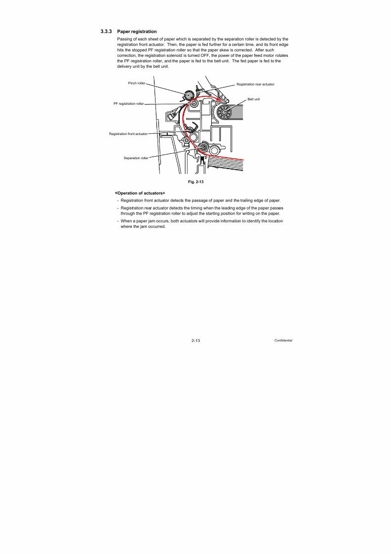
7/18/2019 Brother Mfc 9125cn 9325cw en 5694 Mfp Sm
http://slidepdf.com/reader/full/brother-mfc-9125cn-9325cw-en-5694-mfp-sm 68/597
2-13 Confidential
3.3.3 Paper registration
Passing of each sheet of paper which is separated by the separation roller is detected by the
registration front actuator. Then, the paper is fed further for a certain time, and its front edge
hits the stopped PF registration roller so that the paper skew is corrected. After such
correction, the registration solenoid is turned OFF, the power of the paper feed motor rotates
the PF registration roller, and the paper is fed to the belt unit. The fed paper is fed to thedelivery unit by the belt unit.
Fig. 2-13
<Operation of actuators>
- Registration front actuator detects the passage of paper and the trailing edge of paper.
- Registration rear actuator detects the timing when the leading edge of the paper passes
through the PF registration roller to adjust the starting position for writing on the paper.
- When a paper jam occurs, both actuators will provide information to identify the location
where the jam occurred.
Registration front actuator
Belt unit
PF registration roller
Pinch roller Registration rear actuator
Separation roller

7/18/2019 Brother Mfc 9125cn 9325cw en 5694 Mfp Sm
http://slidepdf.com/reader/full/brother-mfc-9125cn-9325cw-en-5694-mfp-sm 69/597
2-14 Confidential
3.3.4 Paper eject
Drive of the fuser/eject drive motor rotates the heat roller and pressure roller of the fuser unit,
and toner on paper is fused as the paper is being fed. Paper moves along the paper eject
guide and is ejected into the output tray from the exit roller 2 with its print side down.
Fig. 2-14
<Operation of actuators>
- The paper eject front actuator detects that the paper passes through the heat roller to detect
that the paper does not wind around the heat roller.
- The paper eject rear actuator detects that the paper passes through the fuser unit to detect
that a paper jam does not occur between the heat roller and exit roller 1.
Memo:
When a paper jam is detected near the paper eject front actuator and paper eject rear
actuator, the paper feed motor is revolved in the reverse direction to move the gears out of
engagement. The heat roller become free, allowing any paper jam to be cleared.
Exit roller 2
Paper eject guide
Paper eject rear actuator
Paper eject front actuator
Exit roller 1
Heat roller
Pressure roller
Back cover
Fuser unit

7/18/2019 Brother Mfc 9125cn 9325cw en 5694 Mfp Sm
http://slidepdf.com/reader/full/brother-mfc-9125cn-9325cw-en-5694-mfp-sm 70/597
2-15 Confidential
3.3.5 Paper supply from manual feed slot and paper eject from back
When making print from the manual feed slot, set papers on it with the print side up. A sheet of
paper which is inserted from the manual feed slot one by one presses the manual paper
actuator, and consequently the actuator detects that there is a sheet of paper. When the manual
paper actuator is turned ON, pick-up from the manual feed slot is given priority. Power of the
paper feed motor rotates the PF registration roller, and a sheet of paper is picked up. When making print while the back cover is open, a printed sheet is ejected from the back with its
print side up.
Fig. 2-15
Manual feed slot
Manual paper actuator
Registration rear actuator
Paper eject front actuator
Back cover
PF registration roller

7/18/2019 Brother Mfc 9125cn 9325cw en 5694 Mfp Sm
http://slidepdf.com/reader/full/brother-mfc-9125cn-9325cw-en-5694-mfp-sm 71/597
2-16 Confidential
3.4 Toner Cartridge
3.4.1 Type of toner cartridge
This product has four types of toner cartridges, K (black), Y (yellow), M (magenta), and C (cyan),
and each toner cartridge has starter toner cartridge and standard toner cartridge. The toner
cartridges supplied with the product are starter toner cartridges, and the toner cartridges whichare sold as consumable parts are standard toner cartridges. There is a difference in the capacity
and inner shape between K and Y/M/C. In addition, the location to install each cartridge is fixed
depending on the colors.
3.4.2 Life of toner cartridge
In the following two cases, this product considers that the toner cartridge reaches its life end
and stops printing thereafter.
- When the remaining toner powder becomes insufficient for printing
- When the number of accumulated rotations of the develop roller reaches a specified value,
and it is considered that the roller cannot maintain sufficient performance
(1) Number of printable pages by a single toner cartridgeWhen making prints in accordance with ISO/IEC 19798, the number of printable pages by
a single toner cartridge is shown in the table below:
(2) Upper limit of number of rotations of develop roller
The upper limit of the number of rotations of the develop roller is shown in the table below:
The graph given in the next page shows the overview of change in the number of printable
pages in the case of making prints on A4-size paper.
Toner cartridge Number of printable pages
Starter Black 1,000 pages
Yellow, Magenta, Cyan 1,000 pages
Standard Black 2,200 pages
Yellow, Magenta, Cyan 1,400 pages
Toner cartridge Upper limit of rotations of the develop roller
Starter Black 26,880 rotations
Yellow, Magenta, Cyan 26,880 rotations
Standard Black 57,600 rotations
Yellow, Magenta, Cyan 38,400 rotations
Memo:
- The number of rotation of the developer roller per page is as follows.
- Number of idling rotation when the printer is turned ON=110.4 rotations
- Number of rotations upon warm-up operation=11.0 rotations
- Number of rotations upon color registration adjustment=42.7 rotations
- Number of rotations upon color density adjustment=56.7 rotations
Note:
The numeral values provided in this page are as of July 2009. These values are subject to
change without prior notice.
Color Monochrome
Number of developer roller rotations for the first page
printed
38.4 rotations 35.1 rotations
Number of developer roller rotations for the second page
and after (in the case of continuous printing)
14.6 rotations 14.5 rotations

7/18/2019 Brother Mfc 9125cn 9325cw en 5694 Mfp Sm
http://slidepdf.com/reader/full/brother-mfc-9125cn-9325cw-en-5694-mfp-sm 72/597
2-17 Confidential
3.4.3 Method of detecting toner life
This product detects the life of the toner cartridges using the following two means.
Detection by the toner sensor
This product has a function to detect the remaining toner by checking the level at which toner
in a cartridge interrupts light using a transmissive light sensor.
Detection by means of rotation rates of the develop roller reached its upper limit
This product has a function to stop the operation even if toner remains when the number of
rotation reaches the upper limit before the develop roller is worn out and becomes unusable.
When toner reaches its life, this product notifies the users about it by displaying a message to
that effect on the LCD. There are two messages to indicate toner reaches its life: “Toner Low”
and “Replace Toner.” While “Toner Low” is displayed on the LCD when the toner sensor
detects a certain amount of toner is used, “Replace Toner” is displayed on the LCD when the
toner sensor detects that usable toner in a toner cartridge is used up or when the number of
rotations of the develop roller reaches its life.
When “Replace Toner” is displayed on the LCD, no print can be made on this machine until the
toner cartridge in question is replaced with a new one.
3.4.4 Relationship between toner amount and life of toner cartridge in numberof rotations of develop roller
The number of printable pages by a single toner cartridge and upper limit of the number of
rotations of the develop roller are provided in the tables in the previous page. When printing
low-duty documents, however, there is a possibility that the number of rotations of the develop
roller reaches the upper limit, and “Replace Toner” is displayed before toner runs out.
Relationship between printable pages of the toner cartridge and remaining toner
Memo:
When the number of rotations of the develop roller reaches the upper limit, “Replace Toner”
is displayed even if toner remains.
Full
Low
Empty
pages
Cartridge Life End
Toner EmptyToner Empty
Low-duty
High-duty
Normal-duty
(ISO/IEC19798)

7/18/2019 Brother Mfc 9125cn 9325cw en 5694 Mfp Sm
http://slidepdf.com/reader/full/brother-mfc-9125cn-9325cw-en-5694-mfp-sm 73/597
2-18 Confidential
<Life of toner cartridge>
The life of the toner cartridge varies according to the average number of print pages per job.
(See the table below.) The number of printable pages is larger when making continuous prints
in one job because deterioration of the develop roller is low.
Relationship between average print page per 1 job and life of toner cartridges
The develop roller also rotates for the warm-up operation, color registration adjustment
operation, and developing bias adjustment operation when the power is turned ON and when
the cover is opened or closed. Therefore, when these operations are frequently performed,
the life of toner cartridges is shortened. (The table below shows the worst case in which the
warm-up operation, color registration adjustment, and developing bias adjustment areperformed when the power is turned ON.)
Life of the toner cartridges in the case that the power is turned OFF/ON for every print job, and
color registration adjustment and developing bias adjustment are performed
Average print page (page/job) 1 2 3 4 5 6 7 8
Cartridge life (Standard-K) 1,500 2,174 2,556 2,803 2,975 3,102 3,200 3,277
Cartridge life (Standard-YMC) 1,000 1,449 1,704 1,869 1,983 2,068 2,133 2,185
Cartridge life (Starter-KYMC) 700 1,014 1,193 1,308 1,388 1,448 1,493 1,529
Average print page (page/job) 1 2 3 4 5 6 7 8
Cartridge life (Standard-K) 232 438 623 789 939 1,076 1,201 1,315
Cartridge life (Standard-YMC) 155 292 415 526 626 717 800 877
Cartridge life (Starter-KYMC) 108 205 291 368 438 502 560 614
Memo:
- This product prohibits the print operation while any of the toner cartridges is not mounted
or when “Replace Toner” is displayed. In other words, neither monochrome printing
without a color toner cartridge nor color printing without a black toner cartridge is
available.
- This product does not have a function to identify colors of the color toner cartridges.
Note:
The numeral values provided in this page are as of July 2009. These values are subject to
change without prior notice.

7/18/2019 Brother Mfc 9125cn 9325cw en 5694 Mfp Sm
http://slidepdf.com/reader/full/brother-mfc-9125cn-9325cw-en-5694-mfp-sm 74/597

7/18/2019 Brother Mfc 9125cn 9325cw en 5694 Mfp Sm
http://slidepdf.com/reader/full/brother-mfc-9125cn-9325cw-en-5694-mfp-sm 75/597
2-20 Confidential
Developing bias voltage
Toner in use tends to have a low print density at the beginning of its use, but the density
gradually becomes higher after a certain period of use if the bias voltage is kept at a certain
level during development.
The properties of the toner is controlled by means of the developing bias voltage. The values
are varied according to counts of the amount of toner used immediately after a toner cartridgeis changed so that excellent print quality of even contrast can be obtained constantly from the
printing start time to the stop time.
In addition, the developing bias voltage of each toner cartridge is periodically corrected so as
to eliminate variation in the density of the four colors.
When the new toner detection mechanism detects the change to a new toner cartridge, the
developing bias voltage is reset.
Fig. 2-17
Note:
If a toner cartridge in use is replaced to a cartridge which has previously been in use before
reaching a toner life, the developing bias voltage will become incorrect and the density will
be changed, and consequently it may cause print failures. Toner cartridges being used
must not be replaced with other ones.
Actual control[Density]
[Voltage]
Print density
Developing bias voltage
[Used toner amount]

7/18/2019 Brother Mfc 9125cn 9325cw en 5694 Mfp Sm
http://slidepdf.com/reader/full/brother-mfc-9125cn-9325cw-en-5694-mfp-sm 76/597
2-21 Confidential
3.4.6 Method of counting the number of toner replacements
This machine keeps the number of times that the toner cartridges are replaced and the page
counters to learn the usage of the machine. These counters will not be deleted even if the
power is turned OFF. The following tables explain the method of counting the counter values
when the toner cartridges are replaced.
<When a brand-new toner cartridge (unused) is inserted after “Replace Toner” is
displayed>
<When a toner cartridge which is not brand-new is inserted after “Replace
Toner” is displayed by toner sensor detection*1>
*1 Excluding a toner cartridge in use in which there is a little toner remained.
*2 The developing bias voltage is reset to the initial setting once when a toner cartridge which
is not brand-new is inserted. After resetting, the developing bias voltage correction is
performed so that the developing bias voltage is corrected according to the amount of
toner.
Corresponding counter, Setting value Operation
Counter of toner cartridge changes + 1
Page counter for each toner cartridge Reset (0)
Coverage for each toner cartridge Reset (0)
Developing bias voltage Reset (Initial setting)
Corresponding counter, Setting value Operation
Counter of toner cartridge changes No count up
Page counter for each toner cartridge Continued
Coverage for each toner cartridge Continued
Developing bias voltage Reset (Initial setting)*2
Note:
While the parameters explained above are separately controlled for 4 color toners, the
same counting method is applied.

7/18/2019 Brother Mfc 9125cn 9325cw en 5694 Mfp Sm
http://slidepdf.com/reader/full/brother-mfc-9125cn-9325cw-en-5694-mfp-sm 77/597
2-22 Confidential
3.5 Principle of Color Overlapping
The human eye distinguishes one color from others by receiving light’s three primary colors
(Red, Green, Blue). When monochrome lights are received, each color can be sensed.
However, when two-color lights, red (R) and green (G), are received, they are recognized as
“yellow”; when three-color lights, red (R), green (G) and blue (B), are received, they arerecognized as “white”. The fineness of coloration is perceived according to the nature of light.
Fig. 2-18
For printed colors, the human eye can perceive them as various colors by distinguishing each
color light reflected off the surface of a sheet of paper.
Theoretically, if cyan, magenta and yellow are mixed, all the colors are not reflected and black
can be shown. However, a black mix is difficult to produce, and black is shown using
blackcolor paint for practical purposes. Using such a principle, color-absorbing paints aremixed to allow many colors to be shown on the surface of a sheet of paper.
(1) Green+Blue
“Cyan” absorbs red (R) light only
among the three-color lights and
reflects green (G) and blue (B) lights,and consequently the light is identified
as “Cyan.”
(2) Red+Blue
“Magenta” absorbs green (G) light only
among the three-color lights and
reflects red (R) and blue (B) lights, and
consequently the light is identified as
“Magenta.”
(3) Blue
If cyan and magenta are mixed, cyan
absorbs red (R) light and magenta
absorbs green (G) light, and only blue
(B) light is reflected. The light is
identified as “blue.”
Fig. 2-19
Red
Green Blue
White
Yellow
Cyan
Magenta
Cyan toner
B G
G
RB
AbsorbedReflected Reflected
Magenta toner
B G R
R
B
AbsorbedReflected Reflected
Cyan toner + Magenta toner
B G R
B
AbsorbedAbsorbedReflected
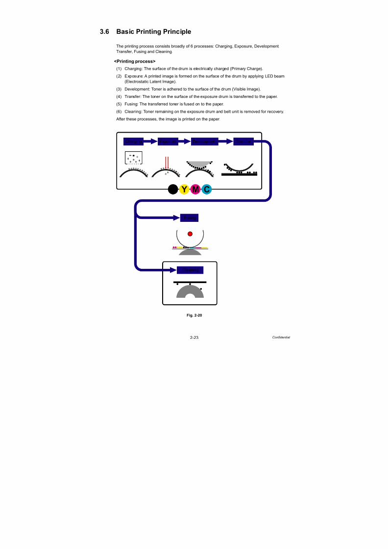
7/18/2019 Brother Mfc 9125cn 9325cw en 5694 Mfp Sm
http://slidepdf.com/reader/full/brother-mfc-9125cn-9325cw-en-5694-mfp-sm 78/597
2-23 Confidential
3.6 Basic Printing Principle
The printing process consists broadly of 6 processes: Charging, Exposure, Development,
Transfer, Fusing and Cleaning.
<Printing process>(1) Charging: The surface of the drum is electrically charged (Primary Charge).
(2) Exposure: A printed image is formed on the surface of the drum by applying LED beam
(Electrostatic Latent Image).
(3) Development: Toner is adhered to the surface of the drum (Visible Image).
(4) Transfer: The toner on the surface of the exposure drum is transferred to the paper.
(5) Fusing: The transferred toner is fused on to the paper.
(6) Cleaning: Toner remaining on the exposure drum and belt unit is removed for recovery.
After these processes, the image is printed on the paper.
Fig. 2-20
CM YK
Charging Exposure Development Transfer
Fusing
Cleaning
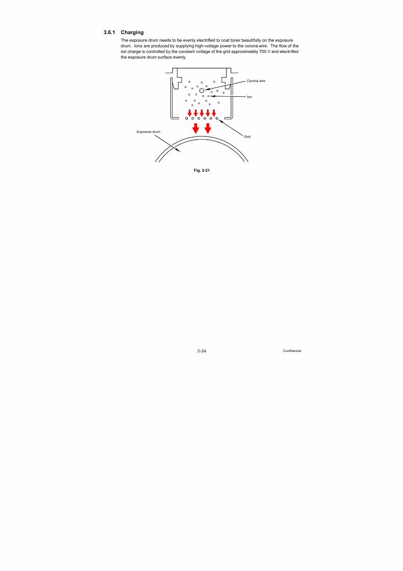
7/18/2019 Brother Mfc 9125cn 9325cw en 5694 Mfp Sm
http://slidepdf.com/reader/full/brother-mfc-9125cn-9325cw-en-5694-mfp-sm 79/597
2-24 Confidential
3.6.1 Charging
The exposure drum needs to be evenly electrified to coat toner beautifully on the exposure
drum. Ions are produced by supplying high-voltage power to the corona wire. The flow of the
ion charge is controlled by the constant voltage of the grid approximately 700 V and electrified
the exposure drum surface evenly.
Fig. 2-21
Corona wire
Ion
Grid
Exposure drum

7/18/2019 Brother Mfc 9125cn 9325cw en 5694 Mfp Sm
http://slidepdf.com/reader/full/brother-mfc-9125cn-9325cw-en-5694-mfp-sm 80/597
2-25 Confidential
3.6.2 Exposure
Exposure is conducted by LED (Light Emitting Diode) arrays.
Four LED arrays for K, Y, M and C are mounted as an LED ASSY on the top cover unit of the
main unit. These four LED arrays do not emit different colors corresponding to toner colors,
and they are the same parts in terms of structure.
Fig. 2-22
On the PCB in the LED array, 4,992 LEDs, which correspond to the total number of the dots of
the 600-dpi print head, are arranged in a staggered pattern. The lens array forms image on
the exposure drum using the light emitted from the LEDs. The surface potential on the
exposure drum, which is evenly charged, is lowered by exposure, and consequently image is
formed.
Fig. 2-23
Memo:
- The focus adjustment of the distance between the LED ASSY and exposure drum is
made by the lower rollers at the both ends of the LED ASSY, and a fixed distance is
maintained.
- Maximum print width is 207.44 mm = 4,900 dots.
LED ASSY
LED array
LED array
Lens array
Roller
Exposure drum
LED array
LED ASSY
Roller
Exposure drum
* Figure of the front view* Figure of the side view
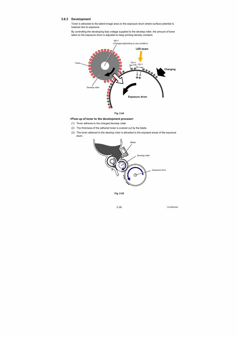
7/18/2019 Brother Mfc 9125cn 9325cw en 5694 Mfp Sm
http://slidepdf.com/reader/full/brother-mfc-9125cn-9325cw-en-5694-mfp-sm 81/597
2-26 Confidential
3.6.3 Development
Toner is attracted to the latent-image area on the exposure drum where surface potential is
lowered due to exposure.
By controlling the developing bias voltage supplied to the develop roller, the amount of toner
taken to the exposure drum is adjusted to keep printing density constant.
Fig. 2-24
<Flow up of toner to the development process>
(1) Toner adheres to the charged develop roller.
(2) The thickness of the adhered toner is evened out by the blade.
(3) The toner adhered to the develop roller is attracted to the exposed areas of the exposure
drum.
Fig. 2-25
Charging
LED beam
Exposure drum
400 V
700 V150 V
Develop roller
Toner
(Changes depending on use condition)
Blade
Develop roller
Exposure drum

7/18/2019 Brother Mfc 9125cn 9325cw en 5694 Mfp Sm
http://slidepdf.com/reader/full/brother-mfc-9125cn-9325cw-en-5694-mfp-sm 82/597
2-27 Confidential
3.6.4 Transfer
By applying a minus charge to the transfer roller of the belt unit, the toner adhered to the
exposure drum is transferred to paper which is traveling on the feed belt.
Fig. 2-26
Fig. 2-27
Memo:The four colors of toner are coated in turn on the paper to form a color:
First comes K, then Y, then M, and then C.
Belt unit
Exposure drum (K) Exposure drum (Y) Exposure drum (M) Exposure drum (C)
Transfer roller
Feed belt
Paper
Toner

7/18/2019 Brother Mfc 9125cn 9325cw en 5694 Mfp Sm
http://slidepdf.com/reader/full/brother-mfc-9125cn-9325cw-en-5694-mfp-sm 83/597
2-28 Confidential
3.6.5 Fusing
The toner transferred on to the paper passes between the heat roller and the pressure roller
in the fuser unit and are fused by heat and pressure. The main CPU detects surface
temperature of the heat roller using the thermistor and turns ON/OFF the halogen heater lamp
to keep the temperature constant.
Fig. 2-28
Memo:
Control of fusing temperature
The fuser unit adjusts such temperature according to types and sizes of paper so as to
keep excellent image quality.
Heat roller
Pressure roller
Fuser unit
Thermistor
Halogen heater lamp
Thermistor

7/18/2019 Brother Mfc 9125cn 9325cw en 5694 Mfp Sm
http://slidepdf.com/reader/full/brother-mfc-9125cn-9325cw-en-5694-mfp-sm 84/597
2-29 Confidential
3.6.6 Toner cleaning
<Flow of toner cleaning>
(1) Toner remaining on the exposure drum which has not completely been transferred on to
the paper is pulled onto the drum cleaner with a lower potential and the drum is cleaned.
(2) After the above step, the potential of the drum cleaner is raised during printing, and suchattracted toner is returned to the exposure drum again. The returned toner is attracted to
the belt unit by lowering the potential of the transfer roller.
(3) The toner attracted to the belt unit is collected by the belt cleaner below the unit, and
stored in the waste toner box.
Fig. 2-29
Memo:
When the toner returns to the exposure drum from the drum cleaner, the develop roller is
separated from the exposure drum to prevent color mixture.
Drum cleaner
Paper
Belt
Develop roller
Exposure drum
Drum cleaner
Exposure
Develop roller Drum cleaner
Belt Transfer roller Belt
Cleaning shaft
Waste toner box
Cleaning
Back-up
roller
roller
Belt cleaner
Paper
drum
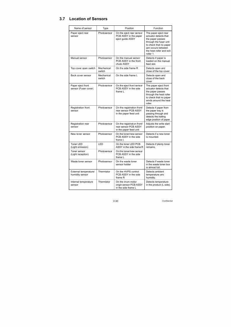
7/18/2019 Brother Mfc 9125cn 9325cw en 5694 Mfp Sm
http://slidepdf.com/reader/full/brother-mfc-9125cn-9325cw-en-5694-mfp-sm 85/597
2-30 Confidential
3.7 Location of Sensors
Name of sensor Type Position Function
Paper eject rear
sensor
Photosensor On the eject rear sensor
PCB ASSY in the papereject guide ASSY
The paper eject rear
actuator detects thatthe paper passes
through the fuser unit
to check that no paper
jam occurs between
the heat roller and exit
roller 1.
Manual sensor Photosensor On the manual sensor
PCB ASSY in the front
chute ASSY
Detects if paper is
loaded on the manual
feed slot.
Top cover open switch Mechanical
switch
On the side frame R Detects open and
close of the top cover.
Back cover sensor Mechanical
switch
On the side frame L Detects open and
close of the back
cover.
Paper eject front
sensor (Fuser cover)
Photosensor On the eject front sensor
PCB ASSY in the side
frame L
The paper eject front
actuator detects that
the paper passes
through the heat roller
to check that no paper
winds around the heat
roller.
Registration front
sensor
Photosensor On the registration front/
rear sensor PCB ASSYin the paper feed unit
Detects if paper from
the paper tray ispassing through and
detects the trailing
edge position of paper.
Registration rear
sensor
Photosensor On the registration front/
rear sensor PCB ASSY
in the paper feed unit
Adjusts the write start
position on paper.
New toner sensor Photosensor On the toner/new sensor
PCB ASSY in the side
frame L
Detects if a new toner
is mounted.
Toner LED
(Light emission)
LED On the toner LED PCB
ASSY in the side frame R
Detects if plenty toner
remains.
Toner sensor
(Light reception)
Photosensor On the toner/new sensor
PCB ASSY in the side
frame L
Waste toner sensor Photosensor On the waste toner
sensor holder
Detects if waste toner
in the waste toner box
is almost full.
External temperature/
humidity sensor
Thermistor On the HVPS control
PCB ASSY in the side
frame R
Detects ambient
temperature and
humidity.
Internal temperature
sensor
Thermistor On the drum motor
origin sensor PCB ASSYin the side frame L
Detects temperature
in the product (L side).

7/18/2019 Brother Mfc 9125cn 9325cw en 5694 Mfp Sm
http://slidepdf.com/reader/full/brother-mfc-9125cn-9325cw-en-5694-mfp-sm 86/597
2-31 Confidential
Name of sensor Type Position Function
Belt thermistor Thermistor Registration sensor
holder ASSY
Detects temperature
in the product (at the
center).
Drum motor origin
sensor
Photosensor On the drum motor
origin sensor PCB ASSY
in the side frame L
Detects the phase of
the drum motor.
Fuser/eject drive
motor sensor
Photosensor On the fuser/eject drive
motor sensor PCB
ASSY in the eject gear
cover
Detects if the fuser/
eject drive motor
operates properly.
Registration mark
sensor L
Photosensor On the registration mark
L PCB ASSY in the
registration sensor
holder ASSY
Measures color
displacement (L side).
Registration mark
sensor R
Photosensor On the registration mark
R PCB ASSY in the
registration sensor
holder ASSY
Measures color
displacement (R side).
Density sensor Photosensor On the registration mark
L PCB ASSY in the
registration sensor
holder ASSY
Measures the density
of each color.
Develop release
sensor
Photosensor On the develop release
sensor PCB ASSY in the
side frame R
Detects the distance
between the develop
roller and exposuredrum.
Document front
sensor
Photosensor On the ADF sensor PCB Detects whether or
not a document is set
on the ADF.
Document rear
sensor
Photosensor On the ADF sensor PCB Detects the timing to
start reading a
document.
ADF cover open
sensor
Photosensor On the ADF sensor PCB Detects whether or
not the ADF cover is
open.Fuser side thermistor Thermistor In the fuser unit Detects the
temperature of the
heat roller.
Fuser center thermistor Thermistor In the fuser unit Detects the
temperature of the
heat roller.

7/18/2019 Brother Mfc 9125cn 9325cw en 5694 Mfp Sm
http://slidepdf.com/reader/full/brother-mfc-9125cn-9325cw-en-5694-mfp-sm 87/597
2-32 Confidential
Location of sensors
Fig. 2-30
Fig. 2-31
<Front>
Eject gear cover
Registration sensor
Waste toner
Registration rear sensor
Registration front sensor
Fuser/eject
Waste toner sensor Paper feed unit
Manual sensor
Registration front/rear sensor PCB ASSY
sensor holder
Registration mark sensor L
drive motorsensor
Density sensor Belt thermistor Registration mark sensor R
holder ASSY
Paper eject guide ASSYPaper eject rear sensor
Toner LED
Develop release
New toner sensor
Drum motor
Paper eject front
<Front>
Toner sensor
Internal temperature
origin sensor
sensor
Top cover openswitch
Back cover sensor
External temperature/
humidity sensor
(Light emission)
(Light reception)
sensor (Fuser cover)
sensor

7/18/2019 Brother Mfc 9125cn 9325cw en 5694 Mfp Sm
http://slidepdf.com/reader/full/brother-mfc-9125cn-9325cw-en-5694-mfp-sm 88/597
2-33 Confidential
Fig. 2-32
Fig. 2-33
Fuser side thermistor
Fuser center thermistor
Fuser unit
<Front>
<Front>
ADF unit
Document front sensor
Document rear sensor
ADF cover open sensor
ADF sensor PCB
Document scanner unit
ASSY
7/18/2019 Brother Mfc 9125cn 9325cw en 5694 Mfp Sm
http://slidepdf.com/reader/full/brother-mfc-9125cn-9325cw-en-5694-mfp-sm 89/597
2-34 Confidential
3.8 Adjustment of Color Registration
In this device, the drum and develop unit are prepared for K, Y, M, and C respectively. Four
color images are combined into one image, and therefore color registration error might occur.
Auto color registration error correction control is to calculate the color registration error amount
and adjust the exposure timing as a means to prevent color registration error.
Execution timing
- When the continuous print elapsed time reaches a designated time, or when the elapsed
time of intermittence print or ready state reaches a designated time.
- Execution from the operation panel (Function code 66), etc.
- Immediately after the top cover is opened and closed.
- After the power is turned OFF and ON. (When the specified period of time has passed since
the previous execution.)
3.8.1 Color registration error in sub/main scanning directionThe color registration test patterns are printed on the belt unit, and the registration mark
sensor reads them. The registration mark sensor is a reflective sensor, and the reflection rate
is different between the surface of the belt unit and toner. The sensor reads the test patterns
using the difference of the reflection rate when the test patterns pass through the sensor. The
displacement in the sub/main scanning direction is calculated based on the distance between
the patterns read by the registration mark sensor, and it is corrected.
3.9 Adjustment of Color DensityTo obtain stable print quality, the density of each toner needs to be maintained at a fixed value.
If the density balance between the colors cannot be kept, the tint becomes unstable, and
accurate color reproduction becomes unavailable. The toner density is changed due to the
charged amount of toner, deterioration of the develop unit, and temperature and humidity in
the level device. Control to keep the stable print density is made by changing the develop bias
voltage.
Execution timing
- Execution is made at a designated timing (specified in WSW55; the default is 24 hours).
(Execution is made when print is started after a specified time has passed.)
- Execution from the operation panel (Function code 83), etc.
- Execution is made when toner is replaced with a new one.
- Execution is made when the ambient temperature is changed.
Operation
The density level adjustment test patterns are printed on the belt unit, and the density sensor
reads them. The read density of each color and the density reference value are compared,
and if any difference is found, the develop bias voltage is controlled to match the print density
to the reference value.

7/18/2019 Brother Mfc 9125cn 9325cw en 5694 Mfp Sm
http://slidepdf.com/reader/full/brother-mfc-9125cn-9325cw-en-5694-mfp-sm 90/597
Confidential
CHAPTER 3ERROR INDICATION AND
TROUBLESHOOTING

7/18/2019 Brother Mfc 9125cn 9325cw en 5694 Mfp Sm
http://slidepdf.com/reader/full/brother-mfc-9125cn-9325cw-en-5694-mfp-sm 91/597
Confidential
CHAPTER 3ERROR INDICATION AND TROUBLESHOOTINGThis chapter details error messages and codes which the incorporated self-diagnostic function of the
machine will display if any error or malfunction occurs. If any error message appears, refer to this
chapter to find which parts should be checked or replaced.
The latter half of this chapter provides sample problems which could occur in the main sections of the
machine and related troubleshooting procedures.
CONTENTS
1. INTRODUCTION ........................................................................................3-1
1.1 Precautions................................................................................................................. 3-1
1.2 Components ............................................................................................................... 3-2
1.3 Initial Check ................................................................................................................3-3
2. ERROR INDICATIONS ..............................................................................3-5
2.1 Error Codes ................................................................................................................3-5
2.2 Error Messages .......................................................................................................... 3-8
2.3 Error Cause and Remedy......................................................................................... 3-11
3. PAPER FEEDING PROBLEMS ...............................................................3-57
3.1 No Feeding ............................................................................................................... 3-57
3.2 Double Feeding ........................................................................................................ 3-58
3.3 Paper Jam ................................................................................................................ 3-58
3.4 Dirt on Paper ............................................................................................................ 3-59
3.5 Wrinkles on Paper .................................................................................................... 3-60
3.6 Curl of Paper ............................................................................................................ 3-60
4. PRINT IMAGE DEFECT FROM PC/USB/FAX RECEPTION
TROUBLESHOOTING .............................................................................3-614.1 Image Defect Examples ........................................................................................... 3-61
4.2 Pitch Indicated in Roller Image................................................................................. 3-62
4.3 Troubleshooting Image Defect.................................................................................. 3-62
5. SOFTWARE SETTING PROBLEMS........................................................3-86
5.1 Cannot Print Data ..................................................................................................... 3-86
6. NETWORK PROBLEMS..........................................................................3-87
6.1 Cannot Make a Print through Network Connection .................................................. 3-87
7. TROUBLESHOOTING OF THE COMMUNICATIONS ERRORS............3-88

7/18/2019 Brother Mfc 9125cn 9325cw en 5694 Mfp Sm
http://slidepdf.com/reader/full/brother-mfc-9125cn-9325cw-en-5694-mfp-sm 92/597
Confidential
7.1 Definition of Error Codes on the Communications List............................................. 3-88
8. TROUBLESHOOTING OF THE CONTROL PANEL COVER ASSY.......3-94
8.1 Nothing is Displayed on the LCD.............................................................................. 3-94
8.2 The control panel cover ASSY does not Work. ........................................................ 3-95
9. TROUBLESHOOTING OF FAX FUNCTIONS .........................................3-96
9.1 FAX can't Send it. ..................................................................................................... 3-96
9.2 Speed Dialing and One-touch Dialing can't be Used................................................ 3-97
9.3 FAX can't be Received. ............................................................................................ 3-97
9.4 No Bell Ring.............................................................................................................. 3-98
9.5 Speaker is Silent During On-hook Dialing. ............................................................... 3-98
9.6 Dialing Function does not Switch between “Tone” and “Pulse.” ............................... 3-99
10. DOCUMENT FEEDING PROBLEMS...................................................3-10010.1 No Feeding........................................................................................................... 3-100
10.2 Double Feeding .................................................................................................... 3-100
10.3 Paper Jam ............................................................................................................ 3-101
10.4 Wrinkles................................................................................................................ 3-102
11. SCANNING IMAGE DEFECT TROUBLESHOOTING .........................3-103
11.1 Image Defect Examples........................................................................................ 3-103
11.2 Troubleshooting Image Defect.............................................................................. 3-103
12. OTHERS PROBLEMS .........................................................................3-106
12.1 The Machine is not Turned on, or the LCD Indication does not Appear............... 3-106
12.2 The Fan does not Work. ....................................................................................... 3-107
12.3 Pickup Function of Paper Tray does not Work. .................................................... 3-107
12.4 The New Toner is not Detected. ........................................................................... 3-108
12.5 Printing from Macintosh Applications Fails. .......................................................... 3-108
12.6 USB Direct Printing does not Work.
(USB direct interface model only)........................................................................... 3-108
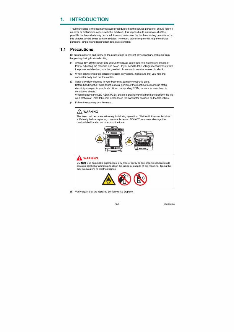
7/18/2019 Brother Mfc 9125cn 9325cw en 5694 Mfp Sm
http://slidepdf.com/reader/full/brother-mfc-9125cn-9325cw-en-5694-mfp-sm 93/597
3-1 Confidential
1. INTRODUCTION
Troubleshooting is the countermeasure procedures that the service personnel should follow if
an error or malfunction occurs with the machine. It is impossible to anticipate all of the
possible troubles which may occur in future and determine the troubleshooting procedures, so
this chapter covers some sample troubles. However, those samples will help the service
personnel pinpoint and repair other defective elements.
1.1 Precautions
Be sure to observe and follow all the precautions to prevent any secondary problems from
happening during troubleshooting.
(1) Always turn off the power and unplug the power cable before removing any covers or
PCBs, adjusting the machine and so on. If you need to take voltage measurements with
the power switched on, take the greatest of care not to receive an electric shock.
(2) When connecting or disconnecting cable connectors, make sure that you hold theconnector body and not the cables.
(3) Static electricity charged in your body may damage electronic parts.
Before handling the PCBs, touch a metal portion of the machine to discharge static
electricity charged in your body. When transporting PCBs, be sure to wrap them in
conductive sheets.
When replacing the LED ASSY/PCBs, put on a grounding wrist band and perform the job
on a static mat. Also take care not to touch the conductor sections on the flat cables.
(4) Follow the warning by all means.
(5) Verify again that the repaired portion works properly.
WARNINGThe fuser unit becomes extremely hot during operation. Wait until it has cooled down
sufficiently before replacing consumable items. DO NOT remove or damage the
caution label located on or around the fuser.
WARNING
DO NOT use flammable substances, any type of spray or any organic solvent/liquids
contains alcohol or ammonia to clean the inside or outside of the machine. Doing this
may cause a fire or electrical shock.

7/18/2019 Brother Mfc 9125cn 9325cw en 5694 Mfp Sm
http://slidepdf.com/reader/full/brother-mfc-9125cn-9325cw-en-5694-mfp-sm 94/597
3-2 Confidential
1.2 Components
Fig. 3-1
LED ASSY
LVPS unit
Fuser unitPaper eject guide ASSY
Side cover R ASSY
High-voltage
HVPS control
Toner LED
Side frame R
Paper feed unitWaste toner sensor
Fuser cover
Back cover
Fuser ejectdrive ASSY
Belt drive ASSY
Main PCB ASSY
Engine PCB ASSY
Access cover
Side cover L ASSY Drum develop
Front cover ASSY
Toner/New sensor
ADF unit
Side frame L
Paper tray
Top cover arm R
Top cover arm L
LED head controlPCB ASSY
drive unit
PCB ASSY
holder ASSY
Main fan ASSY
LV fan ASSY
PCB ASSY
power supply
PCB ASSY
Document scanner unit Panel unit
Joint cover sub ASSY
Front cover
NCU PCB ASSY
Speaker unit
top ASSY
PCB ASSY
USB direct interfacerelay PCB ASSY
Registration sensor holder ASSY

7/18/2019 Brother Mfc 9125cn 9325cw en 5694 Mfp Sm
http://slidepdf.com/reader/full/brother-mfc-9125cn-9325cw-en-5694-mfp-sm 95/597
3-3 Confidential
1.3 Initial Check
Check the following items before attempting to repair the machine.
Operating environment
(1) Put your machine on a flat, stable surface such as a desk that is free of vibration and
shocks.
(2) Use the machine in a well-ventilated room; use the machine within the following ranges of
temperature and humidity: temperature between 10 °C and 32.5 °C (50 °F to 90.5 °F) ,
and the relative humidity is maintained between 20 % and 80 %.
(3) Ensure the machine is not exposed to direct sunlight, excessive heat, moisture, or dust.
(4) Keep the machine horizontal when you carry it. To prevent injuries when moving or lifting
this machine, make sure to use at least two people.
Fig. 3-2
Power supply
(1) The AC input power supply described on the rating plate of the machine should be within
±10 % of the rated voltage.
(2) The AC input power supply is within the regulated value.
(3) The cables and harnesses are connected correctly.
(4) The fuses are not blown.
Paper
(1) A recommended type of paper is being used. (Refer to “2.5 Paper” in Chapter 1.)
(2) The paper is not damp.
(3) The paper is not short-grained paper or acid paper.
Consumable parts
(1) The drum unit (including the toner cartridge) is installed correctly.
(2) The belt unit and waste toner box are installed correctly.

7/18/2019 Brother Mfc 9125cn 9325cw en 5694 Mfp Sm
http://slidepdf.com/reader/full/brother-mfc-9125cn-9325cw-en-5694-mfp-sm 96/597
3-4 Confidential
Others
(1) Condensation
When the machine is moved from a cold place into a warm room, condensation may
occur inside the machine, causing various problems as listed below.
- Condensation on the optical surfaces such as the LED array may cause the print image
to be light.- If the exposure drum is cold, the electrical resistance of the photosensitive layer is
increased, making it impossible to obtain the correct contrast when printing.
- Condensation on the charge unit may cause corona charge leakage.
- Condensation on the plate and separation pad may cause paper feed problems.
If condensation has occurred, leave the machine for at least two hours to allow it to reach
room temperature.
If the drum unit is unpacked soon after it is moved from a cold place to a warm room,
condensation may occur inside the unit which may cause incorrect images. Instruct the
user to allow the unit to come to room temperature before unpacking it. This will take one
or two hours.
(2) Low temperature
The motor may not drive normally under the low temperature environment. This is due to
there being too much load to drive each unit. In this case, the “Low Temperature/
Increase room temperature to allow the machine to operate” message will appear on
the LCD.
Increase the room temperature when the above message is indicated.
Cleaning
Use a soft dry lint-free cloth.
WARNINGDO NOT use flammable substances, any type of spray or any organic solvent/liquids
contains alcohol or ammonia to clean the inside or outside of the machine. Doing this may
cause a fire or electrical shock.

7/18/2019 Brother Mfc 9125cn 9325cw en 5694 Mfp Sm
http://slidepdf.com/reader/full/brother-mfc-9125cn-9325cw-en-5694-mfp-sm 97/597
3-5 Confidential
2. ERROR INDICATIONS
This machine includes a self-diagnosis function. If the machine does not work normally it
judges that an error has occurred, and indicates the corresponding error message on the LCD,
which in turn helps the service men to quickly find out the problem.
2.1 Error Codes
Error codes
Problem Refer to:
Error codes
Problem Refer to:
10 Color registration adjustment failure
(Error, which cannot be recorded,
occurs.)
3-11 20 LED ASSY error (K) 3-15
21 LED ASSY error (Y) 3-15
22 LED ASSY error (M) 3-15
23 LED ASSY error (C) 3-15
24 Internal temperature sensor error 3-1511 Color registration adjustment failure
(Toner of the color which being used
reached the end of life.)
3-11 25 Develop drive motor error 3-16
26 Belt drive motor error 3-16
28 Drum drive motor error 3-16
29 Belt cleaner drive motor error 3-16
2A Develop release motor error 3-17
12 Color registration adjustment failure
(Incorrect measurement value of
color registration adjustment.)
3-11 2C Toner/New sensor PCB error (K) 3-17
2D Toner/New sensor PCB error (Y) 3-17
2E Toner/New sensor PCB error (M) 3-17
2F Toner/New sensor PCB error (C) 3-17
31 Density sensor error 3-1813 Developing bias correction failure
(Error, which cannot be recorded,
occurs.)
3-12 32 Density sensor shutter performance
malfunction
3-18
33 Right color registration sensor error 3-19
14 Developing bias correction failure
(Toner life end)
3-12 34 Left color registration sensor error 3-19
36 HVPS PCB error in ready state 3-20
15 Developing bias correction failure
(Incorrect measurement value of
developing bias correction)
3-12 37 Belt thermistor error 3-20
38 External temperature sensor error 3-21
39 External humidity sensor error 3-21
16 Color registration adjustment failure
(Error, which cannot be recorded,
occurs.)
3-13 3A Engine PCB transfer error 3-21
3B Main PCB RAM error 3-21
3E NVRAM transfer error 3-21
17 Color registration adjustment failure
(Toner life end)
3-13 40 HVPS PCB error in operating 3-20
42 HVPS control PCB transfer error 3-22
18 Color registration adjustment failure
(Incorrect measurement value of
color registration adjustment)
3-13 43 Main/Engine ASIC transfer error 3-22
44 No toner cartridge (K) 3-23
45 No toner cartridge (Y) 3-23
1A Dew condensation on high-voltage
power supply PCB
3-14 46 No toner cartridge (M) 3-23
47 No toner cartridge (C) 3-23
1B Drum error (C) 3-14 48 Drum life end (K) 3-23
1C Drum error (M) 3-14 49 Drum life end (Y) 3-231D Drum error (Y) 3-14 4A Drum life end (M) 3-23
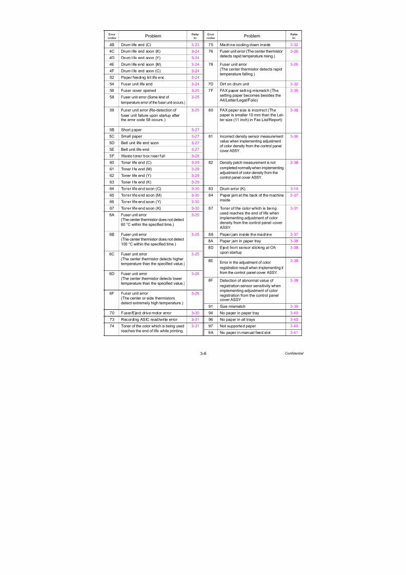
7/18/2019 Brother Mfc 9125cn 9325cw en 5694 Mfp Sm
http://slidepdf.com/reader/full/brother-mfc-9125cn-9325cw-en-5694-mfp-sm 98/597
3-6 Confidential
4B Drum life end (C) 3-23 75 Machine cooling down inside 3-32
4C Drum life end soon (K) 3-24 76 Fuser unit error (The center thermistor
detects rapid temperature rising.)
3-26
4D Drum life end soon (Y) 3-24
4E Drum life end soon (M) 3-24 78 Fuser unit error(The center thermistor detects rapid
temperature falling.)
3-264F Drum life end soon (C) 3-24
52 Paper feeding kit life end 3-24
54 Fuser unit life end 3-24 7D Dirt on drum unit 3-32
56 Fuser cover opened 3-25 7F FAX paper setting mismatch (The
setting paper becomes besides the
A4/Letter/Legal/Folio)
3-35
58 Fuser unit error (Some kind of
temperature error of the fuser unit occurs.)
3-25
59 Fuser unit error (Re-detection of
fuser unit failure upon startup afterthe error code 58 occurs.)
3-25 80 FAX paper size is incorrect (The
paper is smaller 10 mm than the Let-
ter size (11 inch) in Fax List/Report)
3-35
5B Short paper 3-27
5C Small paper 3-27 81 Incorrect density sensor measurement
value when implementing adjustment
of color density from the control panel
cover ASSY.
3-36
5D Belt unit life end soon 3-27
5E Belt unit life end 3-27
5F Waste toner box near full 3-28
60 Toner life end (C) 3-29 82 Density patch measurement is not
completed normally when implementing
adjustment of color density from the
control panel cover ASSY.
3-36
61 Toner life end (M) 3-29
62 Toner life end (Y) 3-29
63 Toner life end (K) 3-29
64 Toner life end soon (C) 3-30 83 Drum error (K) 3-14
65 Toner life end soon (M) 3-30 84 Paper jam at the back of the machineinside
3-37
66 Toner life end soon (Y) 3-30
67 Toner life end soon (K) 3-30 87 Toner of the color which is being
used reaches the end of life when
implementing adjustment of color
density from the control panel cover
ASSY.
3-31
6A Fuser unit error
(The center thermistor does not detect
60 °C within the specified time.)
3-25
6B Fuser unit error
(The center thermistor does not detect
100 °C within the specified time.)
3-25 88 Paper jam inside the machine 3-37
8A Paper jam in paper tray 3-38
8D Eject front sensor sticking at ON
upon startup
3-38
6C Fuser unit error
(The center thermistor detects highertemperature than the specified value.)
3-25
8E Error in the adjustment of color
registration result when implementing it
from the control panel cover ASSY.
3-39
6D Fuser unit error
(The center thermistor detects lower
temperature than the specified value.)
3-26
8F Detection of abnormal value of
registration sensor sensitivity when
implementing adjustment of color
registration from the control panelcover ASSY
3-39
6F Fuser unit error
(The center or side thermistors
detect extremely high temperature.)
3-26
91 Size mismatch 3-39
70 Fuser/Eject drive motor error 3-30 94 No paper in paper tray 3-40
73 Recording ASIC read/write error 3-31 96 No paper in all trays 3-40
74 Toner of the color which is being used
reaches the end of life while printing.
3-31 97 Not supported paper 3-40
9A No paper in manual feed slot 3-41
Error codes
Problem Refer to:
Error codes
Problem Refer to:

7/18/2019 Brother Mfc 9125cn 9325cw en 5694 Mfp Sm
http://slidepdf.com/reader/full/brother-mfc-9125cn-9325cw-en-5694-mfp-sm 99/597
3-7 Confidential
Error codes
Problem Refer to:
Error codes
Problem Refer to:
9DDetection of incorrect registration sensor
measurement value when implementing
adjustment of color registration from thecontrol panel cover ASSY
3-39 C3 Identification failure for a new toner
cartridge (C)
3-46
C6 Pressure engagement/disengagement
failure of toner cartridge
3-47
9EToner of the color which is being
used reaches the end of life when
implementing adjustment of color
registration from the control panel
cover ASSY.
3-31 C7 Insufficient memory 3-47
C8 RAM area for secure data full 3-47
C9 DIMM error 3-48
CA Excess current to USB device 3-48
CB No belt unit 3-49
9F No paper while printing 3-41 CE No waste toner box 3-49
A1 Top cover opened 3-42 CF Waste toner box full 3-50
A2 During scanning, 90 cm or longer of
a document is detected
3-42 D1 Modem initialization failed 3-50
DE Thermistor of fuser unit
misconnected
3-50
A3 Document rear sensor is not turned
on when feeding the document
3-42
E0 Program error 3-51
A4 ADF cover opened 3-43 E1 Program error 3-51
A5 FAX scanning error (Warning) 3-43 E2 Temperature error of heat roller 3-51
A6 FAX scanning error (Error) 3-43 E3 Drum motor origin sensor failure 3-51
A7 Scanning color parameter file failure 3-44 E6 Write error in EEPROM 3-21
A8 Scanning color parameter matching
miss
3-44 E9 Maintenance monitor error 3-52
EC Main fan error 3-52
AD DMA transfer error 3-44 ED Communication with the wireless
LAN PCB cannot be established
upon startup of the power supply
3-52
AF CIS home position sensor is not
turned off.
3-44
B0 Document scanner unit FFCdetection error 3-45 EE Unavailability of communication afterconnecting to the wireless LAN PCB
is detected
3-53
B1 Dark level offset data level error for
scanning
3-45
EF Low-voltage power supply PCB failure 3-53
B2 Gain control data level error for
scanning
3-45 F2 Waste toner box near full 3-53
F4 Waste toner box life end 3-54
B7 A/D converter standard voltage
failure; at High side
3-45 F8 Battery connection error 3-54
F9 Power turned OFF while the function
code 74 is being executed and
“PARAMETER INT” is being
displayed
3-54
B8 A/D converter standard voltage
failure; at Low side
3-45
B9 Scanning light adjustment error is
detected
3-45
FA No drum unit (K) 3-55
BB White level data error 3-46 FB No drum unit (C) 3-55
BD Black level data error 3-46 FC No drum unit (M) 3-55
C0 Identification failure for a new toner
cartridge (K)
3-46 FD No drum unit (Y) 3-55
FE Detection of incorrect measurement
value of density sensor sensitivity
calibration
3-56
C1 Identification failure for a new toner
cartridge (Y)
3-46
C2 Identification failure for a new toner
cartridge (M)
3-46 FF Overcurrent error of wireless LAN
PCB
3-56
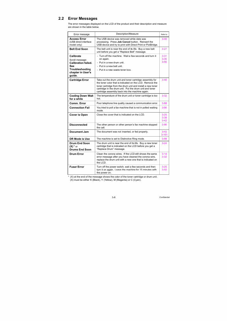
7/18/2019 Brother Mfc 9125cn 9325cw en 5694 Mfp Sm
http://slidepdf.com/reader/full/brother-mfc-9125cn-9325cw-en-5694-mfp-sm 100/597
3-8 Confidential
2.2 Error Messages
The error messages displayed on the LCD of the product and their description and measure
are shown in the table below.
* (X) at the end of the message shows the color of the toner cartridge or drum unit.
(X) must be either K (Black), Y (Yellow), M (Magenta) or C (Cyan).
Error message Description/Measure Refer to:
Access Error (USB direct interface
model only)
The USB device was removed while data was
processing. Press Job Cancel button. Reinsert the
USB device and try to print with Direct Print or PictBridge.
3-48
Belt End Soon The belt unit is near the end of its life. Buy a new belt
unit before you get a “Replace Belt” message.
3-27
Calibrate
Scroll message:
Calibration failed.See
Troubleshooting
chapter in User'sguide.
- Turn off the machine. Wait a few seconds and turn it
on again.
- Put in a new drum unit.
- Put in a new belt unit.
- Put in a new waste toner box.
3-31
3-36
3-56
Cartridge Error Take out the drum unit and toner cartridge assembly for
the toner color that is indicated on the LCD. Remove the
toner cartridge from the drum unit and install a new tonercartridge in the drum unit. Put the drum unit and toner
cartridge assembly back into the machine again.
3-46
Cooling Down Waitfor a while
The temperature of the drum unit or toner cartridge is too
hot.
3-32
Comm. Error Poor telephone line quality caused a communication error. 3-88
Connection Fail You tried to poll a fax machine that is not in polled waitingmode. 3-96
Cover is Open Close the cover that is indicated on the LCD. 3-25
3-38
3-42
Disconnected The other person or other person’s fax machine stopped
the call.
3-96
Document Jam The document was not inserted, or fed properly. 3-42
3-101
DR Mode is Use The machine is set to Distinctive Ring mode. 3-98
Drum End Soon(X) * or
Drums End Soon
The drum unit is near the end of its life. Buy a new toner
cartridge that is indicated on the LCD before you get a
“Replace Drum” message.
3-24
Drum Error Clean the corona wires. If the LCD still shows the same
error message after you have cleaned the corona wire,
replace the drum unit with a new one that is indicated on
the LCD.
3-14
3-32
Fuser Error Turn off the power switch, wait a few seconds and then
turn it on again. Leave the machine for 15 minutes with
the power on.
3-25
3-50

7/18/2019 Brother Mfc 9125cn 9325cw en 5694 Mfp Sm
http://slidepdf.com/reader/full/brother-mfc-9125cn-9325cw-en-5694-mfp-sm 101/597
3-9 Confidential
* (X) at the end of the message shows the color of the toner cartridge or drum unit.(X) must be either K (Black), Y (Yellow), M (Magenta) or C (Cyan).
Error message Description/Measure Refer to:
Jam XXX Carefully pull out the jammed paper from the area shown
in the message.
3-37
3-38
3-58
Low Temperature Increase room temperature to allow the machine tooperate.
---
Manual Feed Put the same size of paper in the manual feed slot as is
shown on the LCD. If the machine is “paused”, press
Start/Black button.
3-41
No Belt Unit Install the belt unit. 3-49
No Paper Put paper in the indicated empty tray. If the problem is
not solved, the paper pick-up roller may be stained.
Clean the paper pick-up roller.
3-40
3-41
No Response/Busy
The number you dialed dose not answer. 3-88
3-96
No Toner Install the toner cartridge that is indicated on the LCD.
Install the drum unit that is indicated on the LCD.
3-55
No Waste Toner Install the waste toner box. 3-49
Out of Memory If the LCD shows this error message when you print the
secure data, press Job Cancel button and delete the
previously stored data. Except in the case of printing
secure data, and add more memory.
3-47
Print Unable ## Turn off the machine. Wait a few seconds and turn it on
again.
3-14
I
3-53
Protected Device(USB direct interface
model only)
The protect switch of the USB flash memory drive is on. 3-483-56
RegistrationScroll message:
Registration failed.SeeTroubleshootingchapter in User'sguide.
- Turn off the machine. Wait a few seconds and turn it
on again.
- Put in a new belt unit.
3-31
3-39
Rename the File
(USB direct interfacemodel only)
There is already a file on the USB flash memory drive
with the same name as the file you are trying to save.
---
Replace Belt It is time to replace the belt unit. Replace the belt unit. 3-27
Replace Drum (X) *or Replace Drums
It is time to replace the drum unit. Replace the drum unit
that is indicated on the LCD.
3-23
Replace Toner It is time to replace the toner cartridge. Replace the
toner cartridge that is indicated on the LCD.
3-29
3-31
Replace WT Box It is time to replace the waste toner box. Replace the
waste toner box.
3-50
3-54
Replace Fuser It is time to replace the fuser unit. Replace the fuser unit. 3-24

7/18/2019 Brother Mfc 9125cn 9325cw en 5694 Mfp Sm
http://slidepdf.com/reader/full/brother-mfc-9125cn-9325cw-en-5694-mfp-sm 102/597
3-10 Confidential
* (X) at the end of the message shows the color of the toner cartridge or drum unit.
(X) must be either K (Black), Y (Yellow), M (Magenta) or C (Cyan).
Error message Description/Measure Refer to:
Replace PF Kit1 It is time to replace the paper feeding kit. Replace the
paper feeding kit.
3-24
Scan Unable XX The machine has a mechanical problem. 3-43
I3-45
Short paper Open the back cover (back-output tray) to let the printed
paper out on the back-output tray and then press Start/
Black button.
3-27
Size Mismatch Put the same size paper in the paper tray or manual feed
slot that is selected in the machine driver, and then press
Start/Black button or select the size of paper which you
set in the paper tray size setting from the control panel
cover ASSY.
3-35
3-39
Small paper Open the back cover (back-output tray) to let the printed
paper out on the back-output tray and then press Start/
Black button.
3-27
Toner Error Dismount the drum unit of the color displayed on the LCD
or all the drum units, and then take out the toner cartridge
from the drum unit(s). Put the toner cartridge back to the
drum unit(s), and remount the drum unit(s) to the printer.
3-47
Toner Low (X) * The toner cartridge is nearly empty. Buy a new toner
cartridge that is indicated on the LCD before you get a
“Replace Toner” message.
3-30
Too Many Files(USB direct interfacemodel only)
There are too many files stored on the USB flash
memory drive.
---
Unusable Device(USB direct interface
model only)
Remove the USB flash memory drive from the USBDirect Interface.
3-483-56
WT Box End Soon The waste toner box will need replacement soon. Buy a
new waste toner box before you get a “Replace WT Box”
message.
3-28
3-53
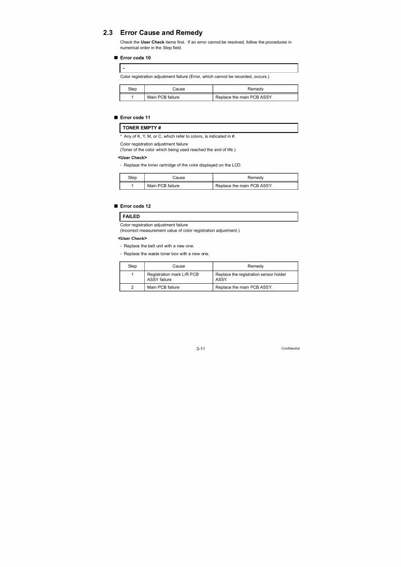
7/18/2019 Brother Mfc 9125cn 9325cw en 5694 Mfp Sm
http://slidepdf.com/reader/full/brother-mfc-9125cn-9325cw-en-5694-mfp-sm 103/597
3-11 Confidential
2.3 Error Cause and Remedy
Check the User Check items first. If an error cannot be resolved, follow the procedures in
numerical order in the Step field.
Error code 10
Color registration adjustment failure (Error, which cannot be recorded, occurs.)
Error code 11
* Any of K, Y, M, or C, which refer to colors, is indicated in #.
Color registration adjustment failure
(Toner of the color which being used reached the end of life.)
<User Check>
- Replace the toner cartridge of the color displayed on the LCD.
Error code 12
Color registration adjustment failure
(Incorrect measurement value of color registration adjustment.)
<User Check>
- Replace the belt unit with a new one.
- Replace the waste toner box with a new one.
-
Step Cause Remedy
1 Main PCB failure Replace the main PCB ASSY.
TONER EMPTY #
Step Cause Remedy
1 Main PCB failure Replace the main PCB ASSY.
FAILED
Step Cause Remedy
1 Registration mark L/R PCB
ASSY failure
Replace the registration sensor holder
ASSY.
2 Main PCB failure Replace the main PCB ASSY.
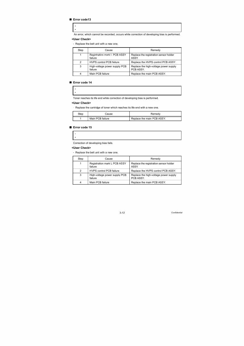
7/18/2019 Brother Mfc 9125cn 9325cw en 5694 Mfp Sm
http://slidepdf.com/reader/full/brother-mfc-9125cn-9325cw-en-5694-mfp-sm 104/597
3-12 Confidential
Error code13
An error, which cannot be recorded, occurs while correction of developing bias is performed.
<User Check>
- Replace the belt unit with a new one.
Error code 14
Toner reaches its life end while correction of developing bias is performed.
<User Check>
- Replace the cartridge of toner which reaches its life end with a new one.
Error code 15
Correction of developing bias fails.
<User Check>
- Replace the belt unit with a new one.
-
-
Step Cause Remedy
1 Registration mark L PCB ASSY
failure
Replace the registration sensor holder
ASSY.
2 HVPS control PCB failure Replace the HVPS control PCB ASSY.
3 High-voltage power supply PCB
failure
Replace the high-voltage power supply
PCB ASSY.
4 Main PCB failure Replace the main PCB ASSY.
-
-
Step Cause Remedy
1 Main PCB failure Replace the main PCB ASSY.
-
-
Step Cause Remedy
1 Registration mark L PCB ASSY
failure
Replace the registration sensor holder
ASSY.
2 HVPS control PCB failure Replace the HVPS control PCB ASSY.
3 High-voltage power supply PCB
failure
Replace the high-voltage power supply
PCB ASSY.
4 Main PCB failure Replace the main PCB ASSY.
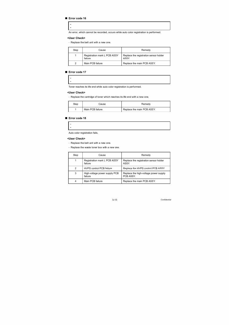
7/18/2019 Brother Mfc 9125cn 9325cw en 5694 Mfp Sm
http://slidepdf.com/reader/full/brother-mfc-9125cn-9325cw-en-5694-mfp-sm 105/597
3-13 Confidential
Error code 16
An error, which cannot be recorded, occurs while auto color registration is performed.
<User Check>
- Replace the belt unit with a new one.
Error code 17
Toner reaches its life end while auto color registration is performed.
<User Check>
- Replace the cartridge of toner which reaches its life end with a new one.
Error code 18
Auto color registration fails.
<User Check>
- Replace the belt unit with a new one.
- Replace the waste toner box with a new one.
-
-
Step Cause Remedy
1 Registration mark L PCB ASSY
failure
Replace the registration sensor holder
ASSY.
2 Main PCB failure Replace the main PCB ASSY.
-
-
Step Cause Remedy
1 Main PCB failure Replace the main PCB ASSY.
--
Step Cause Remedy
1 Registration mark L PCB ASSY
failure
Replace the registration sensor holder
ASSY.
2 HVPS control PCB failure Replace the HVPS control PCB ASSY.
3 High-voltage power supply PCB
failure
Replace the high-voltage power supply
PCB ASSY.
4 Main PCB failure Replace the main PCB ASSY.
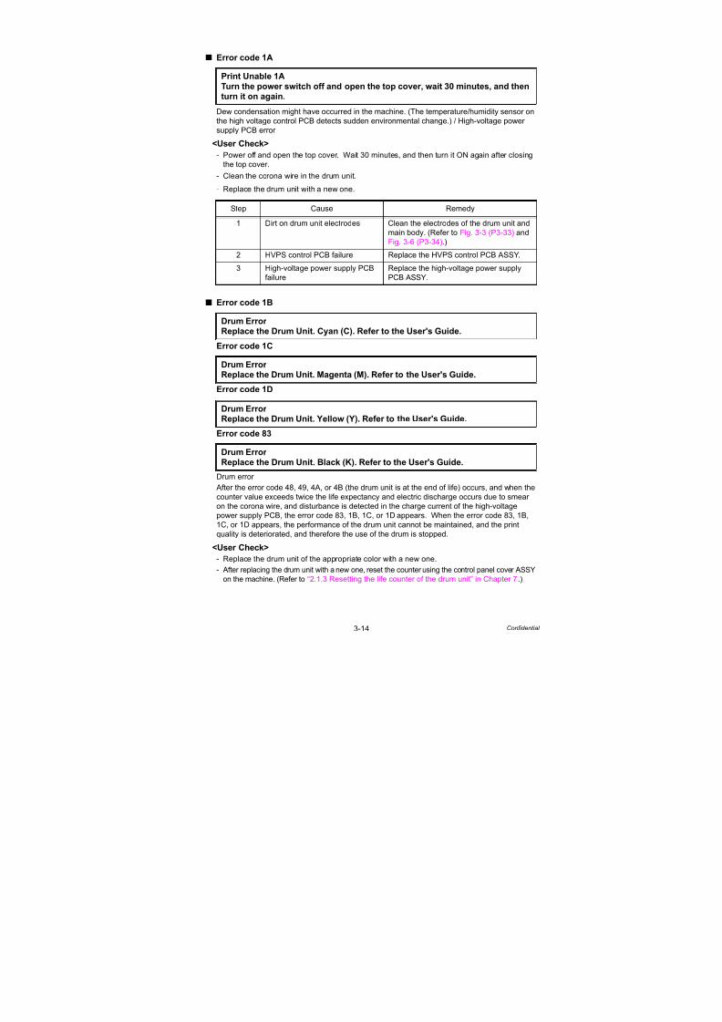
7/18/2019 Brother Mfc 9125cn 9325cw en 5694 Mfp Sm
http://slidepdf.com/reader/full/brother-mfc-9125cn-9325cw-en-5694-mfp-sm 106/597
3-14 Confidential
Error code 1A
Dew condensation might have occurred in the machine. (The temperature/humidity sensor onthe high voltage control PCB detects sudden environmental change.) / High-voltage power
supply PCB error
<User Check>
- Power off and open the top cover. Wait 30 minutes, and then turn it ON again after closing
the top cover.
- Clean the corona wire in the drum unit.
- Replace the drum unit with a new one.
Error code 1B
Error code 1C
Error code 1D
Error code 83
Drum error
After the error code 48, 49, 4A, or 4B (the drum unit is at the end of life) occurs, and when the
counter value exceeds twice the life expectancy and electric discharge occurs due to smear
on the corona wire, and disturbance is detected in the charge current of the high-voltage
power supply PCB, the error code 83, 1B, 1C, or 1D appears. When the error code 83, 1B,
1C, or 1D appears, the performance of the drum unit cannot be maintained, and the print
quality is deteriorated, and therefore the use of the drum is stopped.
<User Check>
- Replace the drum unit of the appropriate color with a new one.
- After replacing the drum unit with a new one, reset the counter using the control panel cover ASSY
on the machine. (Refer to “2.1.3 Resetting the life counter of the drum unit” in Chapter 7.)
Print Unable 1A
Turn the power switch off and open the top cover, wait 30 minutes, and thenturn it on again.
Step Cause Remedy
1 Dirt on drum unit electrodes Clean the electrodes of the drum unit and
main body. (Refer to Fig. 3-3 (P3-33) andFig. 3-6 (P3-34).)
2 HVPS control PCB failure Replace the HVPS control PCB ASSY.
3 High-voltage power supply PCB
failure
Replace the high-voltage power supply
PCB ASSY.
Drum Error Replace the Drum Unit. Cyan (C). Refer to the User's Guide.
Drum Error Replace the Drum Unit. Magenta (M). Refer to the User's Guide.
Drum Error Replace the Drum Unit. Yellow (Y). Refer to the User's Guide.
Drum Error
Replace the Drum Unit. Black (K). Refer to the User's Guide.

7/18/2019 Brother Mfc 9125cn 9325cw en 5694 Mfp Sm
http://slidepdf.com/reader/full/brother-mfc-9125cn-9325cw-en-5694-mfp-sm 107/597
3-15 Confidential
Error code 20 (K), 21 (Y), 22 (M), 23 (C)
LED ASSY error (EEPROM access error of the LED head)
Error code 24
Internal temperature sensor error
Print Unable 20
Turn the power off and then back on again.
Print Unable 21
Turn the power off and then back on again.
Print Unable 22
Turn the power off and then back on again.
Print Unable 23
Turn the power off and then back on again.
Step Cause Remedy
1 FFC connection failure of each
LED ASSY
Check the FFC connection of the
appropriate color and reconnect it.
2 LED head control PCB failure Replace the LED head control PCB ASSY.
3 Failure of each LED ASSY Replace the LED ASSY of the appropriate
color.
4 Main PCB failure Replace the main PCB ASSY.
5 Low-voltage power supply PCB
failure
Replace the low-voltage power supply
PCB ASSY.
Print Unable 24Turn the power off and then back on again.
Step Cause Remedy
1 Internal temperature sensor
failure
Replace the drum motor origin sensor
PCB ASSY.
2 Engine PCB failure Replace the engine PCB ASSY.
3 Main PCB failure Replace the main PCB ASSY.

7/18/2019 Brother Mfc 9125cn 9325cw en 5694 Mfp Sm
http://slidepdf.com/reader/full/brother-mfc-9125cn-9325cw-en-5694-mfp-sm 108/597
3-16 Confidential
Error code 25
Develop drive motor error (Incorrect synchronized signal of the develop drive motor)
Error code 26
Belt drive motor error
Error code 28
Drum drive motor error (Incorrect synchronized signal of the drum drive motor)
Error code 29
Belt cleaner drive motor error (Incorrect synchronized signal of the belt cleaner drive motor)
Print Unable 25
Turn the power off and then back on again.
Print Unable 26
Turn the power off and then back on again.
Print Unable 28Turn the power off and then back on again.
Print Unable 29
Turn the power off and then back on again.
Step Cause Remedy
1 Harness connection failure of
motor
Check the harness connection of the
appropriate motor and reconnect it.
2 Motor failure Replace the appropriate motor.
3 Engine PCB failure Replace the engine PCB ASSY.
4 Main PCB failure Replace the main PCB ASSY.
5 Low-voltage power supply PCB
failure
Replace the low-voltage power supply
PCB ASSY.
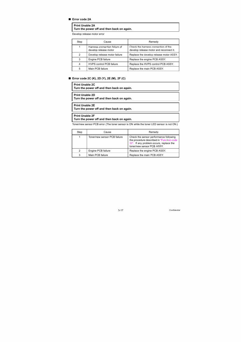
7/18/2019 Brother Mfc 9125cn 9325cw en 5694 Mfp Sm
http://slidepdf.com/reader/full/brother-mfc-9125cn-9325cw-en-5694-mfp-sm 109/597
3-17 Confidential
Error code 2A
Develop release motor error
Error code 2C (K), 2D (Y), 2E (M), 2F (C)
Toner/new sensor PCB error (The toner sensor is ON while the toner LED sensor is not ON.)
Print Unable 2A
Turn the power off and then back on again.
Step Cause Remedy
1 Harness connection failure of
develop release motor
Check the harness connection of the
develop release motor and reconnect it.
2 Develop release motor failure Replace the develop release motor ASSY.
3 Engine PCB failure Replace the engine PCB ASSY.
4 HVPS control PCB failure Replace the HVPS control PCB ASSY.
5 Main PCB failure Replace the main PCB ASSY.
Print Unable 2C
Turn the power off and then back on again.
Print Unable 2D
Turn the power off and then back on again.
Print Unable 2E
Turn the power off and then back on again.
Print Unable 2FTurn the power off and then back on again.
Step Cause Remedy
1 Toner/new sensor PCB failure Check the sensor performance following
the procedure described in “Function code
32”. If any problem occurs, replace the
toner/new sensor PCB ASSY.
2 Engine PCB failure Replace the engine PCB ASSY.
3 Main PCB failure Replace the main PCB ASSY.

7/18/2019 Brother Mfc 9125cn 9325cw en 5694 Mfp Sm
http://slidepdf.com/reader/full/brother-mfc-9125cn-9325cw-en-5694-mfp-sm 110/597
3-18 Confidential
Error code 31
Density sensor error (Incorrect measurement value of the density sensor)
Error code 32
Density sensor shutter performance malfunction
<User Check>
- Check if there is a scratch, dirt or the like on the belt unit. If there is, replace the belt unit
with a new one.
Print Unable 31
Turn the power off and then back on again.
Print Unable 32
Turn the power off and then back on again.
Step Cause Remedy
1 Harness connection failure of
registration mark L PCB ASSY
Check the harness connection between
the registration mark L PCB ASSY and
registration mark relay PCB ASSY, and
the one between the registration mark
relay PCB ASSY and engine PCB ASSY.
Then, reconnect them.
2 Harness connection failure of
density sensor shutter solenoid
Check the harness connection of the
density sensor shutter solenoid and
reconnect it.
3 Registration mark L PCB failure Replace the registration sensor holder
ASSY.4 Engine PCB failure Replace the engine PCB ASSY.
5 Main PCB failure Replace the main PCB ASSY.

7/18/2019 Brother Mfc 9125cn 9325cw en 5694 Mfp Sm
http://slidepdf.com/reader/full/brother-mfc-9125cn-9325cw-en-5694-mfp-sm 111/597
3-19 Confidential
Error code 33
Right color registration sensor error
(Incorrect reading value of the color registration sensor (Right))
Error code 34
Left color registration sensor error
(Incorrect reading value of the color registration sensor (Left))
<User Check>
- Check if there is a scratch, dirt or the like on the belt unit. If there is, replace the belt unit
with a new one.
Print Unable 33
Turn the power off and then back on again.
Print Unable 34Turn the power off and then back on again.
Step Cause Remedy
1 Harness connection failure of
registration mark PCB ASSY
Check the harness connection of the
registration mark PCB ASSY and
reconnect it.
2 Registration mark PCB failure Check the performance of the registration
mark sensor following the procedure
described in “Function code 75”. If any
problem occurs, replace the registration
sensor holder ASSY.
3 Engine PCB failure Replace the engine PCB ASSY.
4 Main PCB failure Replace the main PCB ASSY.
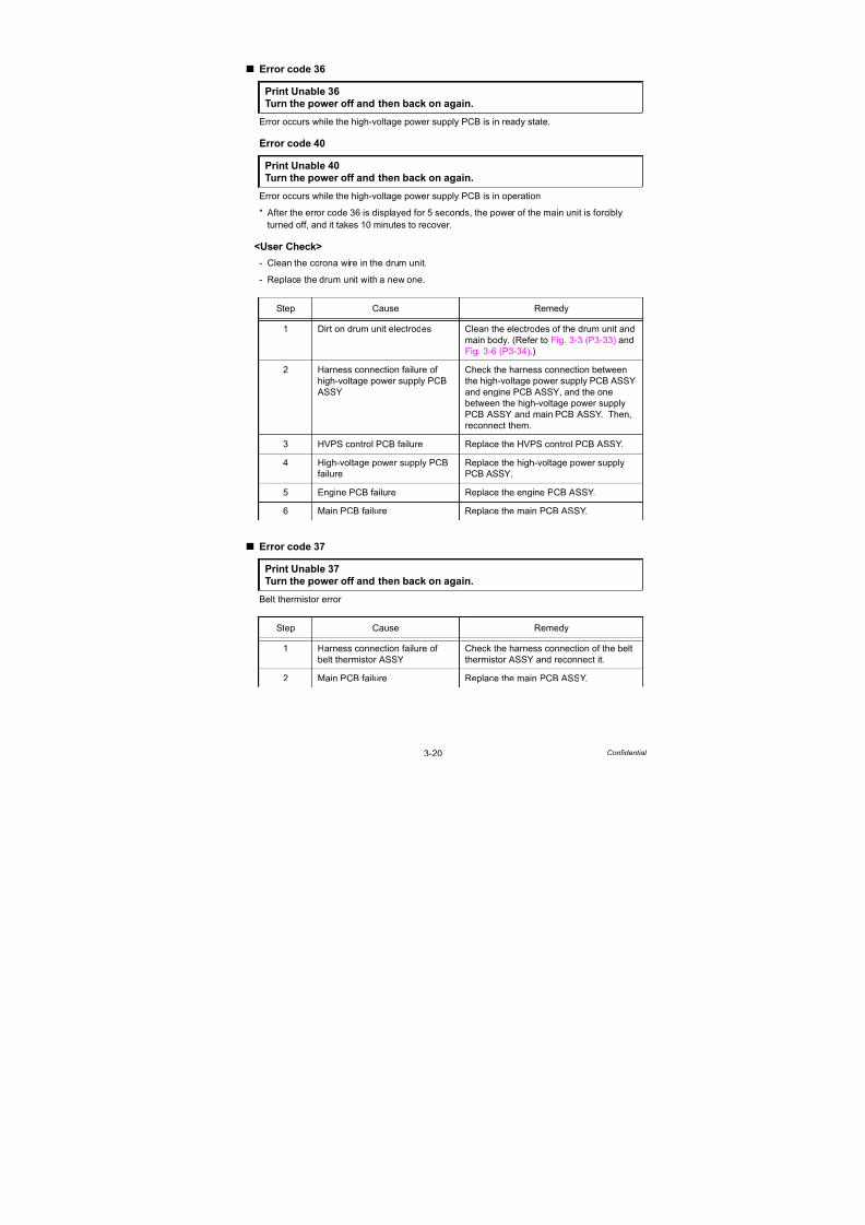
7/18/2019 Brother Mfc 9125cn 9325cw en 5694 Mfp Sm
http://slidepdf.com/reader/full/brother-mfc-9125cn-9325cw-en-5694-mfp-sm 112/597
3-20 Confidential
Error code 36
Error occurs while the high-voltage power supply PCB is in ready state.
Error code 40
Error occurs while the high-voltage power supply PCB is in operation
* After the error code 36 is displayed for 5 seconds, the power of the main unit is forcibly
turned off, and it takes 10 minutes to recover.
<User Check>
- Clean the corona wire in the drum unit.
- Replace the drum unit with a new one.
Error code 37
Belt thermistor error
Print Unable 36
Turn the power off and then back on again.
Print Unable 40
Turn the power off and then back on again.
Step Cause Remedy
1 Dirt on drum unit electrodes Clean the electrodes of the drum unit and
main body. (Refer to Fig. 3-3 (P3-33) and
Fig. 3-6 (P3-34).)
2 Harness connection failure of
high-voltage power supply PCB
ASSY
Check the harness connection between
the high-voltage power supply PCB ASSY
and engine PCB ASSY, and the one
between the high-voltage power supply
PCB ASSY and main PCB ASSY. Then,reconnect them.
3 HVPS control PCB failure Replace the HVPS control PCB ASSY.
4 High-voltage power supply PCB
failure
Replace the high-voltage power supply
PCB ASSY.
5 Engine PCB failure Replace the engine PCB ASSY.
6 Main PCB failure Replace the main PCB ASSY.
Print Unable 37
Turn the power off and then back on again.
Step Cause Remedy
1 Harness connection failure of
belt thermistor ASSY
Check the harness connection of the belt
thermistor ASSY and reconnect it.
2 Main PCB failure Replace the main PCB ASSY.
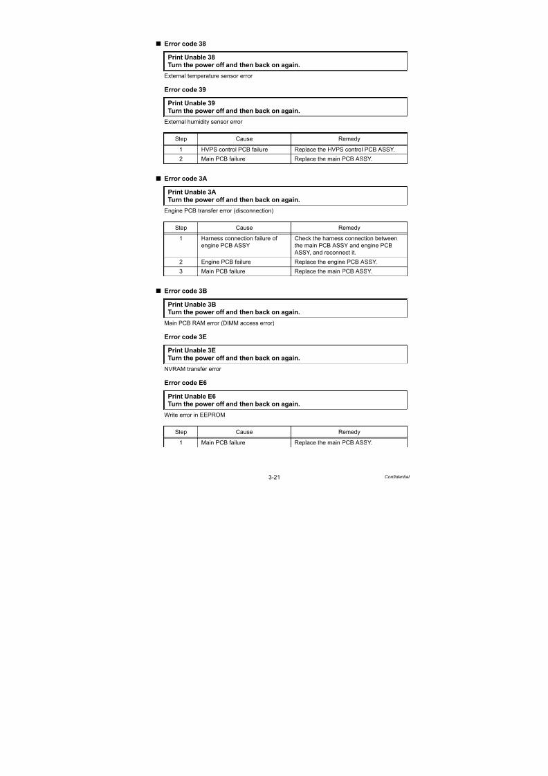
7/18/2019 Brother Mfc 9125cn 9325cw en 5694 Mfp Sm
http://slidepdf.com/reader/full/brother-mfc-9125cn-9325cw-en-5694-mfp-sm 113/597
3-21 Confidential
Error code 38
External temperature sensor error
Error code 39
External humidity sensor error
Error code 3A
Engine PCB transfer error (disconnection)
Error code 3B
Main PCB RAM error (DIMM access error)
Error code 3E
NVRAM transfer error
Error code E6
Write error in EEPROM
Print Unable 38
Turn the power off and then back on again.
Print Unable 39
Turn the power off and then back on again.
Step Cause Remedy
1 HVPS control PCB failure Replace the HVPS control PCB ASSY.
2 Main PCB failure Replace the main PCB ASSY.
Print Unable 3A
Turn the power off and then back on again.
Step Cause Remedy
1 Harness connection failure of
engine PCB ASSY
Check the harness connection between
the main PCB ASSY and engine PCB
ASSY, and reconnect it.
2 Engine PCB failure Replace the engine PCB ASSY.3 Main PCB failure Replace the main PCB ASSY.
Print Unable 3BTurn the power off and then back on again.
Print Unable 3ETurn the power off and then back on again.
Print Unable E6Turn the power off and then back on again.
Step Cause Remedy
1 Main PCB failure Replace the main PCB ASSY.

7/18/2019 Brother Mfc 9125cn 9325cw en 5694 Mfp Sm
http://slidepdf.com/reader/full/brother-mfc-9125cn-9325cw-en-5694-mfp-sm 114/597
3-22 Confidential
Error code 42
HVPS control PCB transfer error
Error code 43
Main/Engine ASIC transfer error
Print Unable 42
Turn the power off and then back on again.
Step Cause Remedy
1 Harness connection failure of
high-voltage power supply PCB
ASSY
Check the harness connection between
the high-voltage power supply PCB ASSY
and HVPS control PCB ASSY, and
reconnect it.
2 Harness connection failure of
HVPS control PCB ASSY
Check the harness connection between
the HVPS control PCB ASSY and main
PCB ASSY, and reconnect it.
3 HVPS control PCB failure Replace the HVPS control PCB ASSY.
4 High-voltage power supply PCB
failure
Replace the high-voltage power supply
PCB ASSY.
5 Main PCB failure Replace the main PCB ASSY.
Print Unable 43
Turn the power off and then back on again.
Step Cause Remedy
1 Harness connection failure
between the main PCB ASSY
and engine PCB ASSY
Check the harness connection between
the main PCB ASSY and engine PCB
ASSY, and reconnect it.
2 Engine PCB failure Replace the engine PCB ASSY.
3 Main PCB failure Replace the main PCB ASSY.

7/18/2019 Brother Mfc 9125cn 9325cw en 5694 Mfp Sm
http://slidepdf.com/reader/full/brother-mfc-9125cn-9325cw-en-5694-mfp-sm 115/597
3-23 Confidential
Error code 44 (K), 45 (Y), 46 (M), 47 (C)
Toner cartridge is not installed into the machine.
(Non-installation is detected by the toner sensor.)
<User Check>
- Install the toner cartridge of the appropriate color.
Error code 48 (K), 49 (Y), 4A (M), 4B (C)
Drum unit is at the end of life. (The drum counter value reaches the end of life.)
* When all four colors reach the end of life at the same time.
<User Check>
- Replace the drum unit of the appropriate color with a new one.
- After replacing the drum unit with a new one, reset the counter using the control panel cover ASSY
on the machine. (Refer to “2.1.3 Resetting the life counter of the drum unit” in Chapter 7.)
No Toner
Open the Top Cover, then install Toner Cartridge. Black (K)
No Toner
Open the Top Cover, then install Toner Cartridge. Yellow (Y)
No Toner
Open the Top Cover, then install Toner Cartridge. Magenta (M)
No Toner
Open the Top Cover, then install Toner Cartridge. Cyan (C)
Step Cause Remedy
1 Harness connection failure of
toner/new sensor PCB ASSY
Check the harness connection of the
toner/new sensor PCB ASSY and
reconnect it.
2 Engine PCB failure Replace the engine PCB ASSY.
3 Main PCB failure Replace the main PCB ASSY.
4 Toner/new sensor PCB failure Replace the toner/new sensor PCB ASSY.
Replace Drum (K)
Replace Drum (Y)
Replace Drum (M)
Replace Drum (C)
Replace Drums
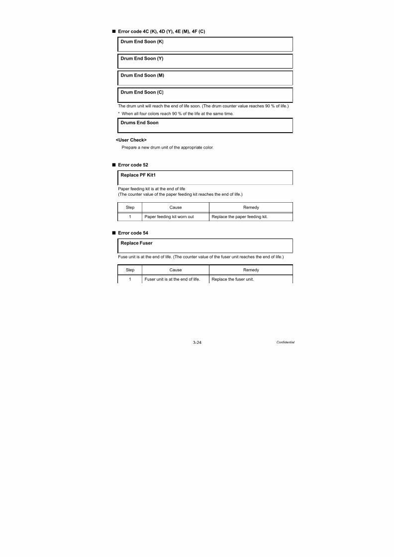
7/18/2019 Brother Mfc 9125cn 9325cw en 5694 Mfp Sm
http://slidepdf.com/reader/full/brother-mfc-9125cn-9325cw-en-5694-mfp-sm 116/597
3-24 Confidential
Error code 4C (K), 4D (Y), 4E (M), 4F (C)
The drum unit will reach the end of life soon. (The drum counter value reaches 90 % of life.)
* When all four colors reach 90 % of the life at the same time.
<User Check>
- Prepare a new drum unit of the appropriate color.
Error code 52
Paper feeding kit is at the end of life.(The counter value of the paper feeding kit reaches the end of life.)
Error code 54
Fuse unit is at the end of life. (The counter value of the fuser unit reaches the end of life.)
Drum End Soon (K)
Drum End Soon (Y)
Drum End Soon (M)
Drum End Soon (C)
Drums End Soon
Replace PF Kit1
Step Cause Remedy
1 Paper feeding kit worn out Replace the paper feeding kit.
Replace Fuser
Step Cause Remedy
1 Fuser unit is at the end of life. Replace the fuser unit.

7/18/2019 Brother Mfc 9125cn 9325cw en 5694 Mfp Sm
http://slidepdf.com/reader/full/brother-mfc-9125cn-9325cw-en-5694-mfp-sm 117/597
3-25 Confidential
Error code 56
Fuser cover opened (Eject front sensor sticking at ON)
<User Check>
- Check if the fuser cover is closed correctly.
Error code 58
Fuser unit error (Some kind of temperature error of the fuser unit occurs.)
Error code 59
Fuser unit error (Re-detection of fuser unit failure upon startup after the error code 58 occurs.)
* If the same error is detected again 15 minutes later, the message below is indicated.
Error code 6A
Fuser unit error (The center thermistor does not detect 60 °C within the specified time.)
Error code 6B
Fuser unit error (The center thermistor does not detect 100 °C within the specified time.)
Error code 6C
Fuser unit error (The center thermistor detects higher temperature than the specified value.)
Refer to the next page for remedy.
Cover is Open
Close the Fuser Cover which can be found behind the Back Cover of themachine.
Step Cause Remedy
1 Paper eject front actuator
catching on some position
Correct catching of the paper eject front
actuator.
2 Eject front sensor PCB failure Replace the eject front sensor PCB ASSY.
3 Main PCB failure Replace the main PCB ASSY.
Fuser Error
Turn the power off, then on again. Leave the machine for 15 min.
Self-Diagnostic
Will Automatically Restart within 15 minutes.
Print Unable 6A
Turn the power off and then back on again.
Print Unable 6BTurn the power off and then back on again.
Print Unable 6C
Turn the power off and then back on again.

7/18/2019 Brother Mfc 9125cn 9325cw en 5694 Mfp Sm
http://slidepdf.com/reader/full/brother-mfc-9125cn-9325cw-en-5694-mfp-sm 118/597
3-26 Confidential
Error code 6D
Fuser unit error (The center thermistor detects lower temperature than the specified value.)
Error code 6F
Fuser unit error (The center or side thermistors detect extremely high temperature.)
Error code 76
Fuser unit error (The center thermistor detects rapid temperature rising.)
Error code 78
Fuser unit error (The center thermistor detects rapid temperature falling.)
Print Unable 6D
Turn the power off and then back on again.
Print Unable 6F
Turn the power off and then back on again.
Print Unable 76
Turn the power off and then back on again.
Print Unable 78Turn the power off and then back on again.
Step Cause Remedy
1 Harness connection failure
between fuser unit connector and
eject front sensor PCB ASSY
Check the harness connection between
the fuser unit connector and eject front
sensor PCB ASSY, and reconnect it.
2 Harness connection failure
between eject front sensor PCB
ASSY and main PCB ASSY
Check the harness connection between
the eject front sensor PCB ASSY and
main PCB ASSY, and reconnect it.
3 Fuser unit failure Replace the fuser unit.
4 Low-voltage power supply PCB
failure
Replace the low-voltage power supply
PCB ASSY.
5 Eject front sensor PCB failure Replace the eject front sensor PCB ASSY.
6 Main PCB failure Replace the main PCB ASSY.

7/18/2019 Brother Mfc 9125cn 9325cw en 5694 Mfp Sm
http://slidepdf.com/reader/full/brother-mfc-9125cn-9325cw-en-5694-mfp-sm 119/597
3-27 Confidential
Error code 5B
Paper of which size is not supported is used. (Paper of less than 148 mm length is fed.)
<User Check>
- Open the back cover and remove the paper.
Error code 5C
Paper of which size is not supported is used.
(Paper of less than 148 mm length is specified from a computer.)
<User Check>
- Open the back cover and make print, or change the paper specified from a computer to
larger-size paper.
Error code 5D
The belt unit will reach the end of life soon. (The belt unit counter value reaches 90 % of life.)
<User Check>
- Prepare a new belt unit.
Error code 5E
The belt unit is at the end of life. (The belt unit counter value reaches the end of life.)
<User Check>
- Replace the belt unit with a new one.
- After replacing the belt unit, reset the counter using the control panel cover ASSY on the
machine. (Refer to “2.1.1 Resetting the life counter of the belt unit” in Chapter 7.)
Short paper
Open the Back Cover and then press Start.
Small paper Open the Back Cover and then press Start.
Belt End Soon
Replace Belt

7/18/2019 Brother Mfc 9125cn 9325cw en 5694 Mfp Sm
http://slidepdf.com/reader/full/brother-mfc-9125cn-9325cw-en-5694-mfp-sm 120/597
3-28 Confidential
Error code 5F
The waste toner box near full. (The waste toner sensor detects the always ON state.)
<User Check>
- Prepare a new waste toner box.
WT Box End Soon
Note:
The same message appears in the case of the error code F2.
Step Cause Remedy
1 Harness connection failure of
waste toner sensor
Check the harness connection of the
waste toner sensor and reconnect it.
2 Waste toner sensor failure Check the sensor performance followingthe procedure described in “Function code
32”. If any problem occurs, replace the
waste toner sensor.
3 HVPS control PCB failure Replace the HVPS control PCB ASSY.
4 Main PCB failure Replace the main PCB ASSY.
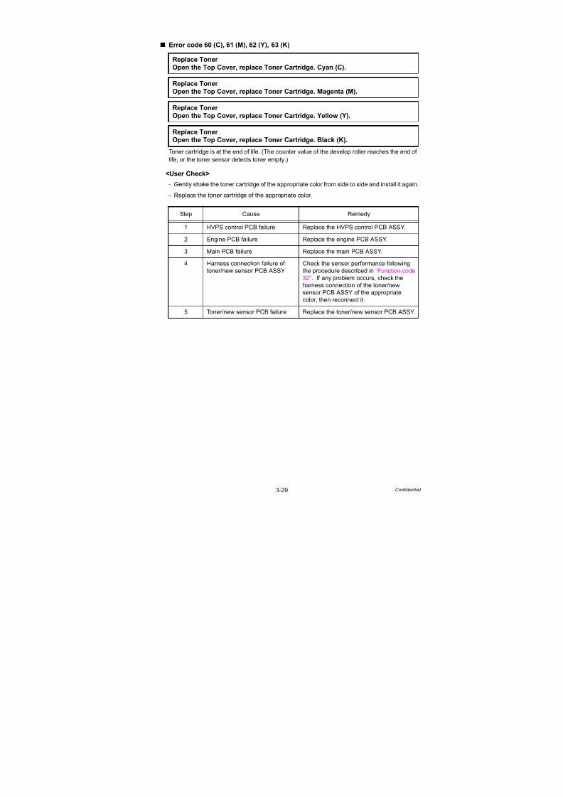
7/18/2019 Brother Mfc 9125cn 9325cw en 5694 Mfp Sm
http://slidepdf.com/reader/full/brother-mfc-9125cn-9325cw-en-5694-mfp-sm 121/597
3-29 Confidential
Error code 60 (C), 61 (M), 62 (Y), 63 (K)
Toner cartridge is at the end of life. (The counter value of the develop roller reaches the end of
life, or the toner sensor detects toner empty.)
<User Check>
- Gently shake the toner cartridge of the appropriate color from side to side and install it again.
- Replace the toner cartridge of the appropriate color.
Replace Toner
Open the Top Cover, replace Toner Cartridge. Cyan (C).
Replace Toner
Open the Top Cover, replace Toner Cartridge. Magenta (M).
Replace Toner
Open the Top Cover, replace Toner Cartridge. Yellow (Y).
Replace Toner
Open the Top Cover, replace Toner Cartridge. Black (K).
Step Cause Remedy
1 HVPS control PCB failure Replace the HVPS control PCB ASSY.
2 Engine PCB failure Replace the engine PCB ASSY.
3 Main PCB failure Replace the main PCB ASSY.
4 Harness connection failure of
toner/new sensor PCB ASSY
Check the sensor performance following
the procedure described in “Function code32”. If any problem occurs, check the
harness connection of the toner/new
sensor PCB ASSY of the appropriate
color, then reconnect it.
5 Toner/new sensor PCB failure Replace the toner/new sensor PCB ASSY.
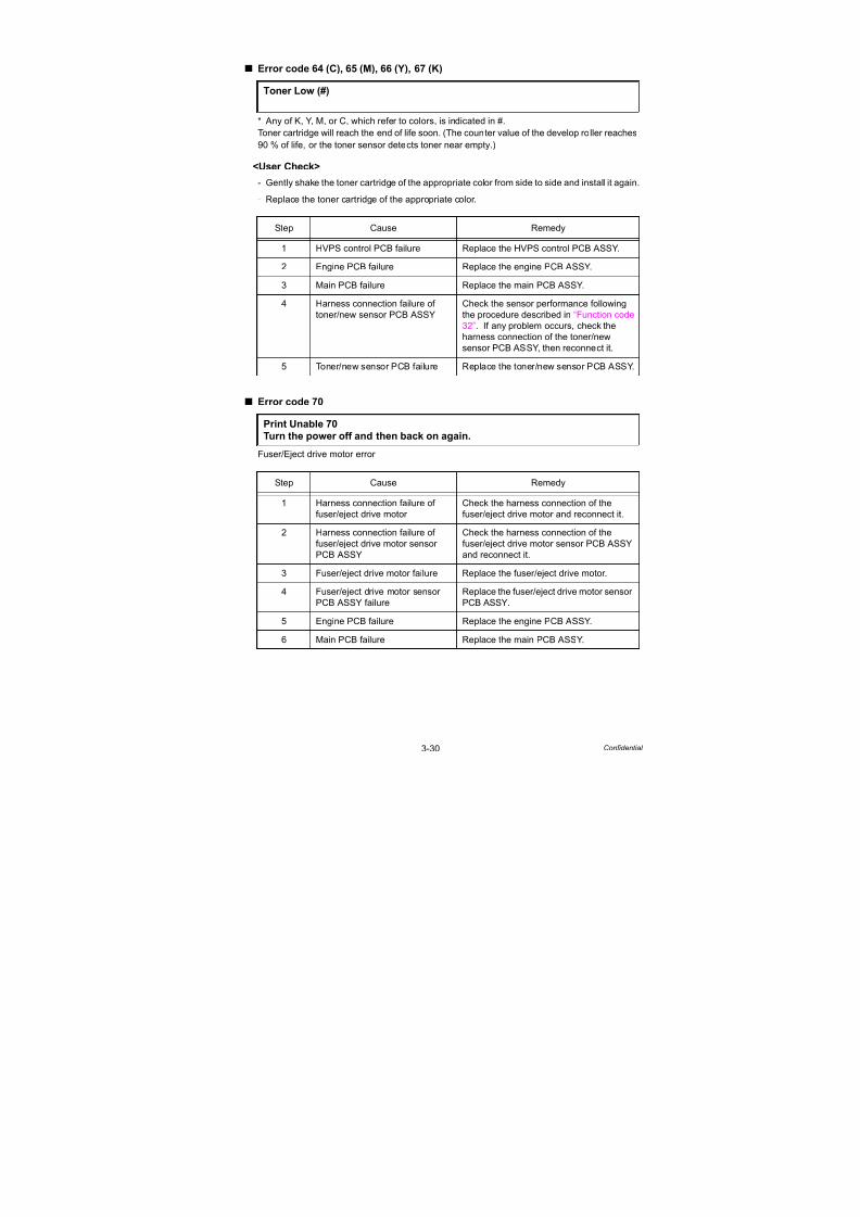
7/18/2019 Brother Mfc 9125cn 9325cw en 5694 Mfp Sm
http://slidepdf.com/reader/full/brother-mfc-9125cn-9325cw-en-5694-mfp-sm 122/597
3-30 Confidential
Error code 64 (C), 65 (M), 66 (Y), 67 (K)
* Any of K, Y, M, or C, which refer to colors, is indicated in #.
Toner cartridge will reach the end of life soon. (The counter value of the develop roller reaches90 % of life, or the toner sensor detects toner near empty.)
<User Check>
- Gently shake the toner cartridge of the appropriate color from side to side and install it again.
- Replace the toner cartridge of the appropriate color.
Error code 70
Fuser/Eject drive motor error
Toner Low (#)
Step Cause Remedy
1 HVPS control PCB failure Replace the HVPS control PCB ASSY.
2 Engine PCB failure Replace the engine PCB ASSY.
3 Main PCB failure Replace the main PCB ASSY.
4 Harness connection failure of
toner/new sensor PCB ASSY
Check the sensor performance following
the procedure described in “Function code
32”. If any problem occurs, check the
harness connection of the toner/new
sensor PCB ASSY, then reconnect it.
5 Toner/new sensor PCB failure Replace the toner/new sensor PCB ASSY.
Print Unable 70
Turn the power off and then back on again.
Step Cause Remedy
1 Harness connection failure of
fuser/eject drive motor
Check the harness connection of the
fuser/eject drive motor and reconnect it.
2 Harness connection failure of
fuser/eject drive motor sensorPCB ASSY
Check the harness connection of the
fuser/eject drive motor sensor PCB ASSYand reconnect it.
3 Fuser/eject drive motor failure Replace the fuser/eject drive motor.
4 Fuser/eject drive motor sensor
PCB ASSY failure
Replace the fuser/eject drive motor sensor
PCB ASSY.
5 Engine PCB failure Replace the engine PCB ASSY.
6 Main PCB failure Replace the main PCB ASSY.

7/18/2019 Brother Mfc 9125cn 9325cw en 5694 Mfp Sm
http://slidepdf.com/reader/full/brother-mfc-9125cn-9325cw-en-5694-mfp-sm 123/597
3-31 Confidential
Error code 73
Recording ASIC read/write error
Error code 74 (This error can be found out only in “Function code 82”.)
Toner of the color which is being used reaches the end of life while printing.
(The counter value of the develop roller reaches the end of life, or the toner sensor detects
toner empty.) This error is not recorded in the error log.
Error code 87
Toner of the color which is being used reaches the end of life when implementing adjustment
of color density from the control panel cover ASSY. (The counter value of the develop roller
reaches the end of life, or the toner sensor detects toner empty.)
Error code 9E
Toner of the color which is being used reaches the end of life when implementing adjustment
of color registration from the control panel cover ASSY. (The counter value of the develop
roller reaches the end of life, or the toner sensor detects toner empty.)
<User Check>
- If any of the toner cartridges reaches the end of life, replace it with a new one.
Print Unable 73
Turn the power off and then back on again.
Step Cause Remedy
1 Harness connection failure of
LED head control PCB ASSY
Check the harness connection between
the main PCB ASSY and LED head
control PCB ASSY, and reconnect them.
2 LED head control PCB failure Replace the LED head control PCB ASSY.
3 Main PCB failure Replace the main PCB ASSY.
Replace Toner Open the Top Cover, replace Toner Cartridge. #
Calibrate
Calibration failed. Insufficient Toner for Calibration.
RegistrationRegistration failed. Insufficient Toner for Registration.
Step Cause Remedy
1 Toner/new sensor PCB failure Check the sensor performance following
the procedure described in “Function code
32”. If any problem occurs, replace the
toner/new sensor PCB ASSY.
2 Engine PCB failure Replace the engine PCB ASSY.

7/18/2019 Brother Mfc 9125cn 9325cw en 5694 Mfp Sm
http://slidepdf.com/reader/full/brother-mfc-9125cn-9325cw-en-5694-mfp-sm 124/597
3-32 Confidential
Error code 75
Cooling down the inside of the machine to protect it.
The machine indicates “Cooling Down” in one of the conditions below.
- The temperature inside the machine is high.
- Both ends of the heat roller are heated extraordinarily.
- The paper media is replaced.
Error code 7D
Dirt on drum unit (Detection of discharge of the corona wire)
<User Check>
- Clean the corona wire in the drum unit.
- Replace the drum unit of the appropriate color with a new one.
Cooling Down
Drum Error
Slide the Green tab on Drum Unit. Black (K)/ Cyan (C)/ Magenta (M)/ Yellow (Y).
Refer to the User's Guide.
Step Cause Remedy
1 Dirt or dust on drum unit
electrodes
Clean the electrodes of the drum unit, belt
unit and main body. (Refer to Fig. 3-3,Fig-3-4 (next page) and Fig. 3-6 (P3-34).)
2 HVPS control PCB failure Replace the HVPS control PCB ASSY.
3 High-voltage power supply PCB
failure
Replace the high-voltage power supply
PCB ASSY.
4 Main PCB failure Replace the main PCB ASSY.

7/18/2019 Brother Mfc 9125cn 9325cw en 5694 Mfp Sm
http://slidepdf.com/reader/full/brother-mfc-9125cn-9325cw-en-5694-mfp-sm 125/597
3-33 Confidential
Electrodes location of the drum unit and toner cartridge
Fig. 3-3
Electrodes location of the belt unit
Fig. 3-4
* Black only

7/18/2019 Brother Mfc 9125cn 9325cw en 5694 Mfp Sm
http://slidepdf.com/reader/full/brother-mfc-9125cn-9325cw-en-5694-mfp-sm 126/597
3-34 Confidential
Electrodes location of waste toner box
Fig. 3-5
Electrodes location of main body
Fig. 3-6
<How to clean the electrodes>
Turn off the power switch. Unplug the machine from the AC power outlet, and leave the
machine for a few minutes. Then, wipe the electrodes above carefully with a dry lint-free cloth.
Be careful not to change the shapes of the electrodes.

7/18/2019 Brother Mfc 9125cn 9325cw en 5694 Mfp Sm
http://slidepdf.com/reader/full/brother-mfc-9125cn-9325cw-en-5694-mfp-sm 127/597
3-35 Confidential
Error code 7F
Fax paper setting mismatch (The setting paper becomes besides the A4/Letter/Legal/Folio)
Error code 80
Fax paper size is incorrect (The paper is smaller 10 mm than the Letter size in Fax List/Report)
<User Check>
- Set the defined size paper.
Size mismatch
Fax received. Set correct paper size in menu.
Size mismatch
Reload correct paper.
Step Cause Remedy
1 Registration front actuator
catching on some position
Correct catching of the registration front
actuator.
2 Main PCB failure Replace the main PCB ASSY.

7/18/2019 Brother Mfc 9125cn 9325cw en 5694 Mfp Sm
http://slidepdf.com/reader/full/brother-mfc-9125cn-9325cw-en-5694-mfp-sm 128/597
3-36 Confidential
Error code 81
Incorrect density sensor measurement value when implementing adjustment of color density
from the control panel cover ASSY.
Error code 82
Density patch measurement is not completed normally when implementing adjustment of color
density from the control panel cover ASSY.
<User Check>
- Check if there is a scratch, dirt or the like on the belt unit. If there is, replace the belt unit with
a new one.
- Check if the genuine toner cartridges are installed in the correct order of colors.
Calibrate
Calibration failed. See Troubleshooting chapter in User’s Guide.
CalibrateCalibration failed. Press Start, and try again.
Step Cause Remedy
1 Density sensor shutter catching
on some position
Correct catching of the density sensor
shutter.
2 Harness connection failure of
registration mark L PCB ASSY
Check the harness connection of the
registration mark L PCB ASSY and
reconnect it.
3 HVPS control PCB failure Replace the HVPS control PCB ASSY.
4 Engine PCB failure Replace the engine PCB ASSY.
5 Main PCB failure Replace the main PCB ASSY.
6 Registration mark L PCB failure Replace the registration sensor holder
ASSY.

7/18/2019 Brother Mfc 9125cn 9325cw en 5694 Mfp Sm
http://slidepdf.com/reader/full/brother-mfc-9125cn-9325cw-en-5694-mfp-sm 129/597
3-37 Confidential
Error code 84
Paper jam at the back of the machine inside
(The eject front sensor sticks at ON after the registration rear actuator is turned OFF.)
Error code 88
Paper jam inside the machine
(The registration rear actuator sticks at ON, or the eject front sensor fails to be turned ON.)
<User Check>
- Check if the paper is jammed. If jammed, remove it.
Jam Rear
Open the Back Cover and remove the jammed paper, then press Start.
Jam InsideOpen the Top Cover, pull out all 4 Drum Units completely and remove the
jammed paper.
Step Cause Remedy
1 Harness connection failure of
registration front/rear sensor
PCB ASSY and eject front
sensor PCB ASSY
Check the harness connections of the
registration front/rear sensor PCB ASSY
and eject front sensor PCB ASSY, and
reconnect them.
2 Registration rear actuator or
paper eject front actuator
catching on some position
Correct catching of the registration rear
actuator or paper eject front actuator.
3 Eject front sensor PCB failure(Error code 84)
Check the sensor performance followingthe procedure described in “Function code
32”. If any problem occurs, replace the
eject front sensor PCB ASSY.
Registration front/rear sensor
PCB failure (Error code 88)
Check the sensor performance following
the procedure described in “Function code
32”. If any problem occurs, replace the
registration front/rear sensor PCB ASSY.
4 HVPS control PCB failure Replace the HVPS control PCB ASSY.
5 Engine PCB failure Replace the engine PCB ASSY.
6 Main PCB failure Replace the main PCB ASSY.

7/18/2019 Brother Mfc 9125cn 9325cw en 5694 Mfp Sm
http://slidepdf.com/reader/full/brother-mfc-9125cn-9325cw-en-5694-mfp-sm 130/597
3-38 Confidential
Error code 8A
Paper jam in the paper tray (The registration front sensor sticks at ON.)
<User Check>
- Check if the paper is jammed in the paper tray. If jammed, remove it.
- Adjust the paper guide corresponding to the paper size.
- Check if too much paper is loaded in the tray.
Error code 8D
Eject front sensor sticking at ON upon startup
<User Check>
- Close the fuser cover.
Jam Tray 1
Remove the jammed paper from Tray 1, then press Start.
Step Cause Remedy
1 Harness connection failure of
registration front/rear sensor
PCB ASSY
Check the harness connection of the
registration front/rear sensor PCB ASSY
and reconnect it.
2 Paper feeding kit worn out Replace the paper feeding kit.
3 Registration front/rear sensor
PCB failure
Check the sensor performance following
the procedure described in “Function code
32”. If any problem occurs, replace the
registration front/rear sensor PCB ASSY.
4 HVPS control PCB failure Replace the HVPS control PCB ASSY.
5 Main PCB failure Replace the main PCB ASSY.
Cover is Open
Make sure there is no paper jammed inside the machine and close the Back
Cover, then press Start.
Step Cause Remedy
1 Harness connection failure of
eject front sensor PCB ASSY
Check the harness connection of the eject
front sensor PCB ASSY and reconnect it.
2 Eject front sensor PCB failure Replace the eject front sensor PCB ASSY.
3 Main PCB failure Replace the main PCB ASSY.
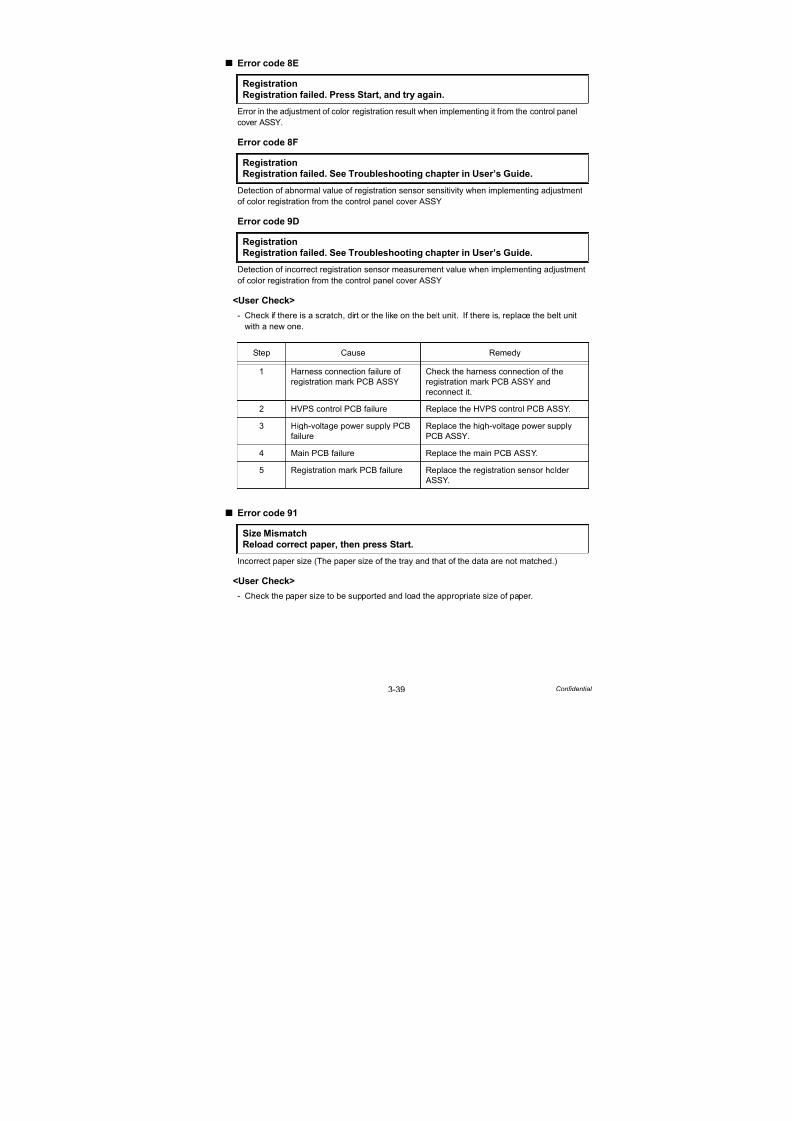
7/18/2019 Brother Mfc 9125cn 9325cw en 5694 Mfp Sm
http://slidepdf.com/reader/full/brother-mfc-9125cn-9325cw-en-5694-mfp-sm 131/597
3-39 Confidential
Error code 8E
Error in the adjustment of color registration result when implementing it from the control panel
cover ASSY.
Error code 8F
Detection of abnormal value of registration sensor sensitivity when implementing adjustment
of color registration from the control panel cover ASSY
Error code 9D
Detection of incorrect registration sensor measurement value when implementing adjustment
of color registration from the control panel cover ASSY
<User Check>
- Check if there is a scratch, dirt or the like on the belt unit. If there is, replace the belt unit
with a new one.
Error code 91
Incorrect paper size (The paper size of the tray and that of the data are not matched.)
<User Check>
- Check the paper size to be supported and load the appropriate size of paper.
Registration
Registration failed. Press Start, and try again.
RegistrationRegistration failed. See Troubleshooting chapter in User’s Guide.
Registration
Registration failed. See Troubleshooting chapter in User’s Guide.
Step Cause Remedy
1 Harness connection failure of
registration mark PCB ASSY
Check the harness connection of the
registration mark PCB ASSY andreconnect it.
2 HVPS control PCB failure Replace the HVPS control PCB ASSY.
3 High-voltage power supply PCB
failure
Replace the high-voltage power supply
PCB ASSY.
4 Main PCB failure Replace the main PCB ASSY.
5 Registration mark PCB failure Replace the registration sensor holder
ASSY.
Size MismatchReload correct paper, then press Start.

7/18/2019 Brother Mfc 9125cn 9325cw en 5694 Mfp Sm
http://slidepdf.com/reader/full/brother-mfc-9125cn-9325cw-en-5694-mfp-sm 132/597
3-40 Confidential
Error code 94
- No paper in paper tray
(The registration front actuator is not turned ON after a certain period of time has passed.)
- Paper tray is not installed into the machine.
<User Check>
- Insert the paper into the paper tray.
- Remount the paper tray to the machine.
Error code 96
No paper in all trays (The manual paper actuator is not ON, and the registration front actuator
is not turned ON after a certain period of time has passed.)
<User Check>- Load the paper into any of the trays.
Error code 97
Not supported paper
<User Check>
- Load paper with the size supported by the product.
No Paper Load <size> paper, then press Start.
Step Cause Remedy
1 Lift arm and roller holder ASSY
not assembled correctly
Be sure to put the boss of the roller holder
ASSY into the hole on the lift arm
securely.
2 Harness connection failure of
registration front/rear sensor
PCB ASSY
Check the harness connection of the
registration front/rear sensor PCB ASSY
and reconnect it.
3 Plate-up function malfunction Replace the paper tray.
4 Registration front sensor failure Check the sensor performance following
the procedure described in “Function code
32”. If any problem occurs, replace the
registration front/rear sensor PCB ASSY.
5 HVPS control PCB failure Replace the HVPS control PCB ASSY.6 Main PCB failure Replace the main PCB ASSY.
No PaperLoad <size> paper, then press Start.
Size Error Specify the correct paper size for Tray 1.

7/18/2019 Brother Mfc 9125cn 9325cw en 5694 Mfp Sm
http://slidepdf.com/reader/full/brother-mfc-9125cn-9325cw-en-5694-mfp-sm 133/597
3-41 Confidential
Error code 9A
No paper in manual feed slot (The manual paper actuator is not turned ON.)
No paper is inserted on the manual feed slot when drum cleaning is executed.
(The manual paper actuator is not turned ON.)
<User Check>
- Insert a paper into the manual feed slot.
Error code 9F
No paper while printing
<User Check>
- Load the paper into the paper tray.
Manual Feed
Load <size> Paper.
Drum Cleaning
Insert the blank paper into the Manual feed slot.
Step Cause Remedy
1 Harness connection failure of
manual sensor PCB ASSY
Check the harness connection of the
manual sensor PCB ASSY and reconnect it.
2 Manual sensor failure Check the sensor performance following
the procedure described in “Function code
32”. If any problem occurs, replace the
manual sensor PCB ASSY.
3 Registration front/rear sensor
PCB failure
Replace the registration front/rear sensor
PCB ASSY.
4 HVPS control PCB failure Replace the HVPS control PCB ASSY.
5 Main PCB failure Replace the main PCB ASSY.
No Paper Load <size> paper, then press Start.

7/18/2019 Brother Mfc 9125cn 9325cw en 5694 Mfp Sm
http://slidepdf.com/reader/full/brother-mfc-9125cn-9325cw-en-5694-mfp-sm 134/597
3-42 Confidential
Error code A1
Top cover opened (The top cover open switch sticks at OFF.)
<User Check>
- Close the top cover.
Error code A2
During scanning, 90 cm or longer of a document is detected
Error code A3
The document rear sensor does not detect the leading edge of a document although the
document is fed farther than a designated distance.
<User Check>
- Check if the document is jammed in the ADF. If it is jammed, remove it.
Cover is OpenClose the Top Cover.
Step Cause Remedy
1 Harness connection failure of top
cover switch ASSY
Check the harness connection of the top
cover switch ASSY and reconnect it.
2 The member to press the top
cover switch at the right side of
the inside of the top cover is
broken.
Replace the top cover sub ASSY.
3 HVPS control PCB failure Replace the HVPS control PCB ASSY.
4 Main PCB failure Replace the main PCB ASSY.
Document JamClear the scanner jam, then press the Stop Key.
Document JamClear the scanner jam, then press the Stop Key.
Step Cause Remedy
1 Document rear actuator catching
on some position.
Correct catching of the document rear
actuator.
2 Harness connection failure of
ADF sensor PCB
Check the harness connection of the ADF
sensor PCB and reconnect it.
3 Document rear sensor failure Replace the ADF sensor PCB ASSY.
4 Main PCB failure Replace the main PCB ASSY.

7/18/2019 Brother Mfc 9125cn 9325cw en 5694 Mfp Sm
http://slidepdf.com/reader/full/brother-mfc-9125cn-9325cw-en-5694-mfp-sm 135/597
3-43 Confidential
Error code A4
The ADF cover open sensor is OFF.
<User Check>
- Close the ADF cover.
Error code A5
Scanning failure upon FAX transmission (Warning at the first occurrence)
<User Check>
- Turn the power switch off and on. Then, try scanning again.
Error code A6
Scanning failure upon FAX transmission (After A5 occurs, the same symptom occurs again
even though the power is turned OFF and ON.)
Cover is Open
Close the ADF cover, then press Stop Key.
Step Cause Remedy
1 ADF cover open sensor actuator
catching on some position.
Correct catching of the ADF cover open
sensor actuator.
2 Harness connection failure of
ADF sensor PCB
Check the harness connection of the ADF
sensor PCB and reconnect it.
3 ADF cover is changed in shape
or cracked.
Replace the ADF cover ASSY.
4 ADF sensor PCB failure Replace the ADF sensor PCB ASSY.
5 Main PCB failure Replace the main PCB ASSY.
Scan Unable A5Remove the original document. Turn the power off, then on again.
Scan Unable A6
See Troubleshooting and routine maintenance chapter in User’s Guide.
Step Cause Remedy
1 Document scanner unit failure Replace the document scanner unit.
2 Main PCB failure Replace the main PCB ASSY.

7/18/2019 Brother Mfc 9125cn 9325cw en 5694 Mfp Sm
http://slidepdf.com/reader/full/brother-mfc-9125cn-9325cw-en-5694-mfp-sm 136/597
3-44 Confidential
Error code A7
Scanning color parameter file failure
Error code A8
Scanning color parameter error for recording the image
Error code AD
Timeout error during waiting for completion of scanning DMA transfer
Error code AF
CIS unit home position error (The home position sensor cannot be detected.)
Scan Unable A7
See Troubleshooting and routine maintenance chapter in User’s Guide.
Scan Unable A8
See Troubleshooting and routine maintenance chapter in User’s Guide.
Step Cause Remedy
1 Document scanner unit failure Replace the document scanner unit.
2 Main PCB failure Replace the main PCB ASSY.
Scan Unable ADRemove the original document. Turn the power off, then on again.
Step Cause Remedy
1 Document scanner unit failure Replace the document scanner unit.
2 Main PCB failure Replace the main PCB ASSY.
Scan Unable AF
See Troubleshooting and routine maintenance chapter in User’s Guide.
Step Cause Remedy
1 Harness connection failure of
home position sensor.
Check the harness connection of the
home position sensor and reconnect it.
2 Document scanner unit failure Replace the document scanner unit.
3 Main PCB failure Replace the main PCB ASSY.
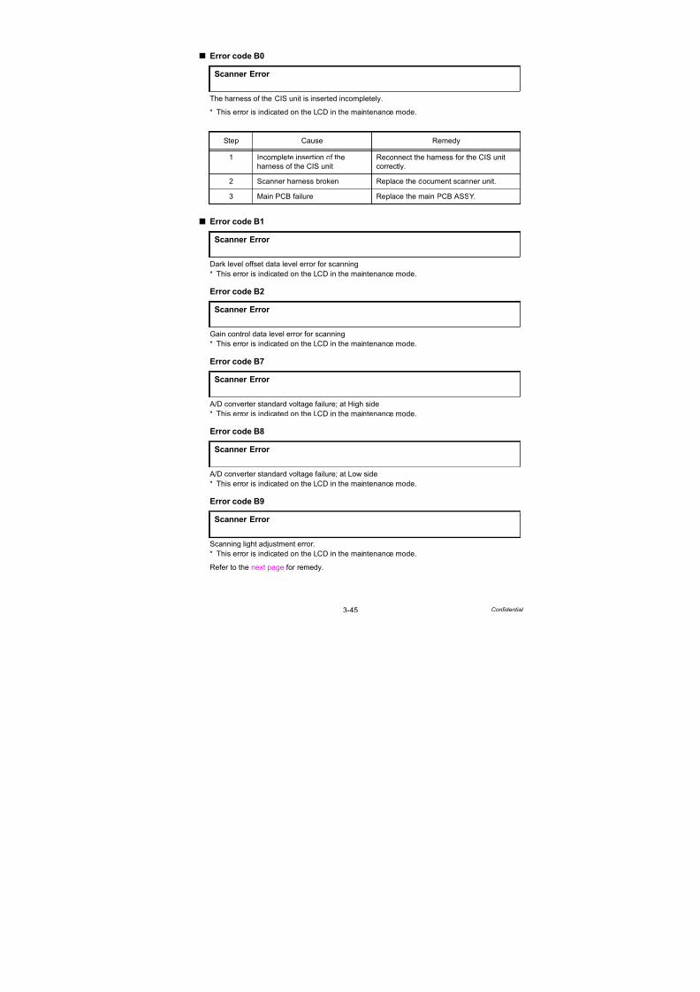
7/18/2019 Brother Mfc 9125cn 9325cw en 5694 Mfp Sm
http://slidepdf.com/reader/full/brother-mfc-9125cn-9325cw-en-5694-mfp-sm 137/597
3-45 Confidential
Error code B0
The harness of the CIS unit is inserted incompletely.
* This error is indicated on the LCD in the maintenance mode.
Error code B1
Dark level offset data level error for scanning
* This error is indicated on the LCD in the maintenance mode.
Error code B2
Gain control data level error for scanning* This error is indicated on the LCD in the maintenance mode.
Error code B7
A/D converter standard voltage failure; at High side
* This error is indicated on the LCD in the maintenance mode.
Error code B8
A/D converter standard voltage failure; at Low side
* This error is indicated on the LCD in the maintenance mode.
Error code B9
Scanning light adjustment error.
* This error is indicated on the LCD in the maintenance mode.
Refer to the next page f or remedy.
Scanner Error
Step Cause Remedy
1 Incomplete insertion of the
harness of the CIS unit
Reconnect the harness for the CIS unit
correctly.
2 Scanner harness broken Replace the document scanner unit.
3 Main PCB failure Replace the main PCB ASSY.
Scanner Error
Scanner Error
Scanner Error
Scanner Error
Scanner Error
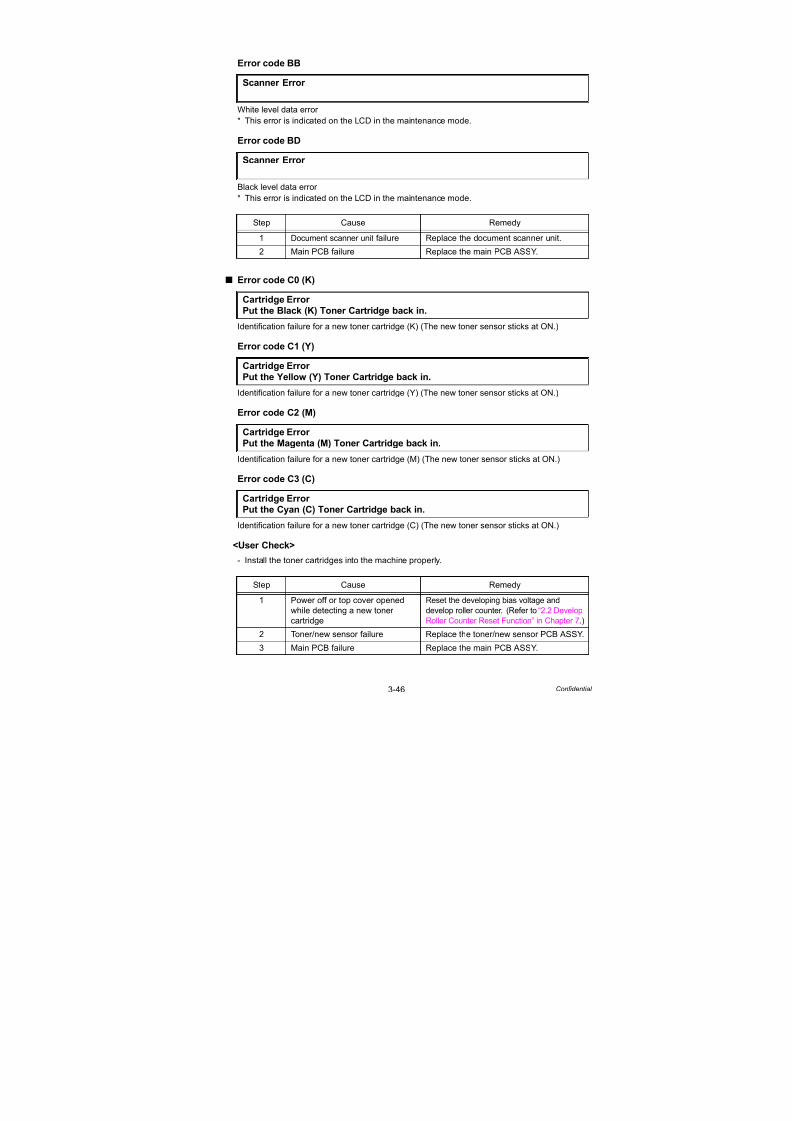
7/18/2019 Brother Mfc 9125cn 9325cw en 5694 Mfp Sm
http://slidepdf.com/reader/full/brother-mfc-9125cn-9325cw-en-5694-mfp-sm 138/597
3-46 Confidential
Error code BB
White level data error
* This error is indicated on the LCD in the maintenance mode.
Error code BD
Black level data error
* This error is indicated on the LCD in the maintenance mode.
Error code C0 (K)
Identification failure for a new toner cartridge (K) (The new toner sensor sticks at ON.)
Error code C1 (Y)
Identification failure for a new toner cartridge (Y) (The new toner sensor sticks at ON.)
Error code C2 (M)
Identification failure for a new toner cartridge (M) (The new toner sensor sticks at ON.)
Error code C3 (C)
Identification failure for a new toner cartridge (C) (The new toner sensor sticks at ON.)
<User Check>
- Install the toner cartridges into the machine properly.
Scanner Error
Scanner Error
Step Cause Remedy
1 Document scanner unit failure Replace the document scanner unit.
2 Main PCB failure Replace the main PCB ASSY.
Cartridge Error
Put the Black (K) Toner Cartridge back in.
Cartridge Error
Put the Yellow (Y) Toner Cartridge back in.
Cartridge Error
Put the Magenta (M) Toner Cartridge back in.
Cartridge Error Put the Cyan (C) Toner Cartridge back in.
Step Cause Remedy
1 Power off or top cover opened
while detecting a new toner
cartridge
Reset the developing bias voltage and
develop roller counter. (Refer to “2.2 Develop
Roller Counter Reset Function” in Chapter 7.)
2 Toner/new sensor failure Replace the toner/new sensor PCB ASSY.
3 Main PCB failure Replace the main PCB ASSY.

7/18/2019 Brother Mfc 9125cn 9325cw en 5694 Mfp Sm
http://slidepdf.com/reader/full/brother-mfc-9125cn-9325cw-en-5694-mfp-sm 139/597
3-47 Confidential
Error code C6
Pressure engagement/disengagement failure of toner cartridge (Develop release sensoroutput error)
Error code C7
Insufficient memory
<User Check>
- Install additional DIMM memory.
- Make a print by dividing data.
Error code C8
RAM area for secure data full
<User Check>
- Delete the stored data.
Toner Error
One or more Toner Cartridges are not detected. Pull out and reinsert all 4Toner Cartridges.
Step Cause Remedy
1 Harness connection failure of
develop release motor
Check the harness connection of the
develop release motor and reconnect it.
2 Harness connection failure of
develop release sensor PCB
ASSY
Check the harness connection of the
develop release sensor PCB ASSY and
reconnect it.
3 Develop release motor failure Replace the develop release motor ASSY.
4 Develop release sensor PCB
failure
Replace the develop release sensor PCB
ASSY.
5 Engine PCB failure Replace the engine PCB ASSY.
6 HVPS control PCB failure Replace the HVPS control PCB ASSY.
7 Main PCB failure Replace the main PCB ASSY.
Out of MemoryAdd more Memory.
Out of MemorySecure Print Data is full. Press Job Cancel and delete the previously storeddata.
Step Cause Remedy
1 Main PCB failure Replace the main PCB ASSY.
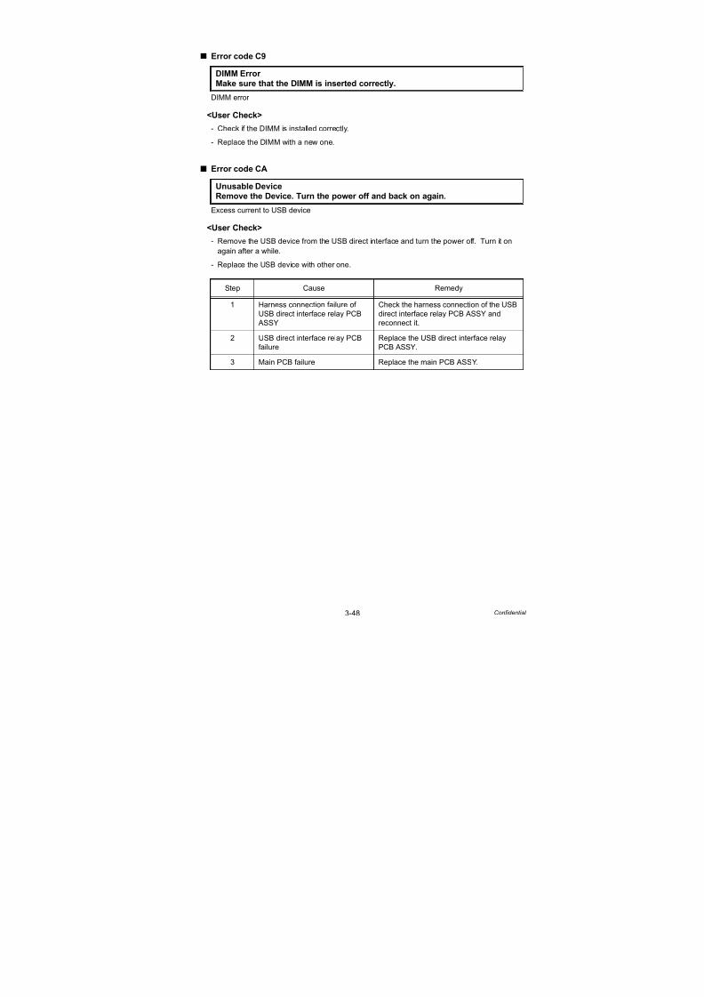
7/18/2019 Brother Mfc 9125cn 9325cw en 5694 Mfp Sm
http://slidepdf.com/reader/full/brother-mfc-9125cn-9325cw-en-5694-mfp-sm 140/597
3-48 Confidential
Error code C9
DIMM error
<User Check>
- Check if the DIMM is installed correctly.
- Replace the DIMM with a new one.
Error code CA
Excess current to USB device
<User Check>
- Remove the USB device from the USB direct interface and turn the power off. Turn it on
again after a while.
- Replace the USB device with other one.
DIMM Error
Make sure that the DIMM is inserted correctly.
Unusable DeviceRemove the Device. Turn the power off and back on again.
Step Cause Remedy
1 Harness connection failure of
USB direct interface relay PCB
ASSY
Check the harness connection of the USB
direct interface relay PCB ASSY and
reconnect it.
2 USB direct interface relay PCBfailure
Replace the USB direct interface relayPCB ASSY.
3 Main PCB failure Replace the main PCB ASSY.

7/18/2019 Brother Mfc 9125cn 9325cw en 5694 Mfp Sm
http://slidepdf.com/reader/full/brother-mfc-9125cn-9325cw-en-5694-mfp-sm 141/597
3-49 Confidential
Error code CB
Belt unit is not installed into the machine.
(The density sensor detects that the belt unit is not installed.)
<User Check>
- Check if the belt unit is installed into the machine.
Error code CE
Waste toner box is not installed into the machine.
(It is detected by turning ON and OFF the waste toner sensor using a shutter.)
<User Check>
- Check if the waste toner box is installed into the machine.
- Replace the waste toner box with a new one.
No Belt Unit
Open the Top Cover, pull out all 4 Drum Units completely and install the Belt
Unit.
Step Cause Remedy
1 Harness connection failure of
registration mark L PCB ASSY
Check the harness connection of the
registration mark L PCB ASSY and
reconnect it.
2 Harness connection failure of
shutter solenoid of the densitysensor
Check the harness connection of shutter
solenoid of the density sensor andreconnect it.
3 Engine PCB failure Replace the engine PCB ASSY.
4 Main PCB failure Replace the main PCB ASSY.
5 Registration mark L PCB failure Replace the registration sensor holder
ASSY.
No Waste Toner Install the Waste Toner Box. Refer to the User’s Guide for instructions.
Step Cause Remedy
1 Harness connection failure of
waste toner sensor
Check the harness connection of the
waste toner sensor and reconnect it.2 HVPS control PCB failure Replace the HVPS control PCB ASSY.
3 Main PCB failure Replace the main PCB ASSY.

7/18/2019 Brother Mfc 9125cn 9325cw en 5694 Mfp Sm
http://slidepdf.com/reader/full/brother-mfc-9125cn-9325cw-en-5694-mfp-sm 142/597
3-50 Confidential
Error code CF
Waste toner box full (500 pages are printed after the waste toner sensor sticks at ON.)
<User Check>
- Replace the waste toner box with a new one.
Error code D1
Modem initialization failed
Error code DE
The connector of the fuser unit thermistor is inserted incorrectly.
(It is detected that the edge temperature is lower than 60°C.)
Replace WT Box
Replace the Waste Toner Box. Refer to the User’s Guide for instructions.
Note:
The same message appears in the case of the error code F4.
Step Cause Remedy
1 Harness connection failure of
waste toner sensor
Check the harness connection of the
waste toner sensor and reconnect it.
2 Waste toner sensor failure Check the sensor performance followingthe procedure described in “Function code
32”. If any problem occurs, replace the
waste toner sensor.
3 HVPS control PCB failure Replace the HVPS control PCB ASSY.
4 Main PCB failure Replace the main PCB ASSY.
Machine Error D1
Step Cause Remedy
1 Main PCB failure Replace the main PCB ASSY.
Print Unable DE
Turn the power off and then back on again.
Step Cause Remedy
1 Connection failure of fuser unit
thermistor connector
Check the connection of the fuser unit
thermistor connector and reconnect it.
2 Fuser unit failure Replace the fuser unit.

7/18/2019 Brother Mfc 9125cn 9325cw en 5694 Mfp Sm
http://slidepdf.com/reader/full/brother-mfc-9125cn-9325cw-en-5694-mfp-sm 143/597
3-51 Confidential
Error code E0
Program error
<User Check>
- Turn the power off and on.
Error code E1
Program error
<User Check>
- Turn the power off and on.
Error code E2
Temperature error of heat roller
(It is detected that the edge temperature is higher than 280°C.)
Error code E3
Drum motor origin sensor failure
Print Unable E0
Turn the power off and then back on again.
Print Unable E1Turn off and on.
Step Cause Remedy
1 Main PCB failure Replace the main PCB ASSY.
Print Unable E2Turn the power off and then back on again.
Step Cause Remedy
1 Fuser unit failure Replace the fuser unit.
2 Eject front sensor PCB failure Replace the eject front sensor PCB ASSY.
3 Main PCB failure Replace the main PCB ASSY.
Print Unable E3Turn the power off and then back on again.
Step Cause Remedy
1 Drum motor origin sensor PCB
failure
Replace the drum motor origin sensor
PCB ASSY.
2 Engine PCB failure Replace the engine PCB ASSY.
3 Main PCB failure Replace the main PCB ASSY.
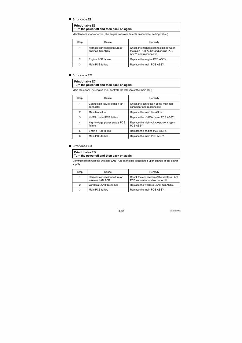
7/18/2019 Brother Mfc 9125cn 9325cw en 5694 Mfp Sm
http://slidepdf.com/reader/full/brother-mfc-9125cn-9325cw-en-5694-mfp-sm 144/597
3-52 Confidential
Error code E9
Maintenance monitor error (The engine software detects an incorrect setting value.)
Error code EC
Main fan error (The engine PCB controls the rotation of the main fan.)
Error code ED
Communication with the wireless LAN PCB cannot be established upon startup of the power
supply
Print Unable E9
Turn the power off and then back on again.
Step Cause Remedy
1 Harness connection failure of
engine PCB ASSY
Check the harness connection between
the main PCB ASSY and engine PCB
ASSY, and reconnect it.
2 Engine PCB failure Replace the engine PCB ASSY.
3 Main PCB failure Replace the main PCB ASSY.
Print Unable EC
Turn the power off and then back on again.
Step Cause Remedy
1 Connection failure of main fan
connector
Check the connection of the main fan
connector and reconnect it.
2 Main fan failure Replace the main fan ASSY.
3 HVPS control PCB failure Replace the HVPS control PCB ASSY.
4 High-voltage power supply PCB
failure
Replace the high-voltage power supply
PCB ASSY.
5 Engine PCB failure Replace the engine PCB ASSY.
6 Main PCB failure Replace the main PCB ASSY.
Print Unable ED
Turn the power off and then back on again.
Step Cause Remedy
1 Harness connection failure of
wireless LAN PCB
Check the connection of the wireless LAN
PCB connector and reconnect it.
2 Wireless LAN PCB failure Replace the wireless LAN PCB ASSY.
3 Main PCB failure Replace the main PCB ASSY.
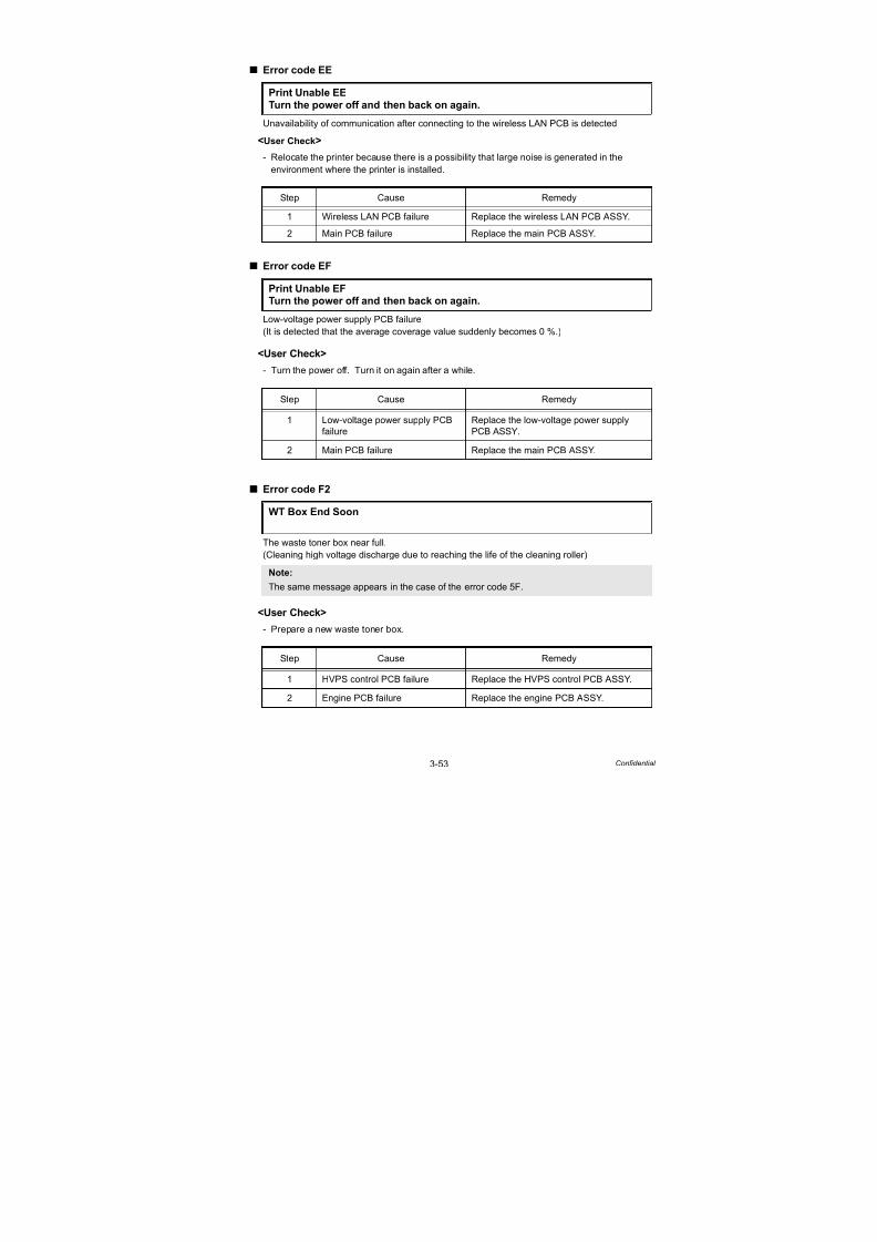
7/18/2019 Brother Mfc 9125cn 9325cw en 5694 Mfp Sm
http://slidepdf.com/reader/full/brother-mfc-9125cn-9325cw-en-5694-mfp-sm 145/597
3-53 Confidential
Error code EE
Unavailability of communication after connecting to the wireless LAN PCB is detected
<User Check>
- Relocate the printer because there is a possibility that large noise is generated in the
environment where the printer is installed.
Error code EF
Low-voltage power supply PCB failure
(It is detected that the average coverage value suddenly becomes 0 %.)
<User Check>
- Turn the power off. Turn it on again after a while.
Error code F2
The waste toner box near full.
(Cleaning high voltage discharge due to reaching the life of the cleaning roller)
<User Check>
- Prepare a new waste toner box.
Print Unable EE
Turn the power off and then back on again.
Step Cause Remedy
1 Wireless LAN PCB failure Replace the wireless LAN PCB ASSY.
2 Main PCB failure Replace the main PCB ASSY.
Print Unable EFTurn the power off and then back on again.
Step Cause Remedy
1 Low-voltage power supply PCBfailure
Replace the low-voltage power supplyPCB ASSY.
2 Main PCB failure Replace the main PCB ASSY.
WT Box End Soon
Note:
The same message appears in the case of the error code 5F.
Step Cause Remedy
1 HVPS control PCB failure Replace the HVPS control PCB ASSY.
2 Engine PCB failure Replace the engine PCB ASSY.
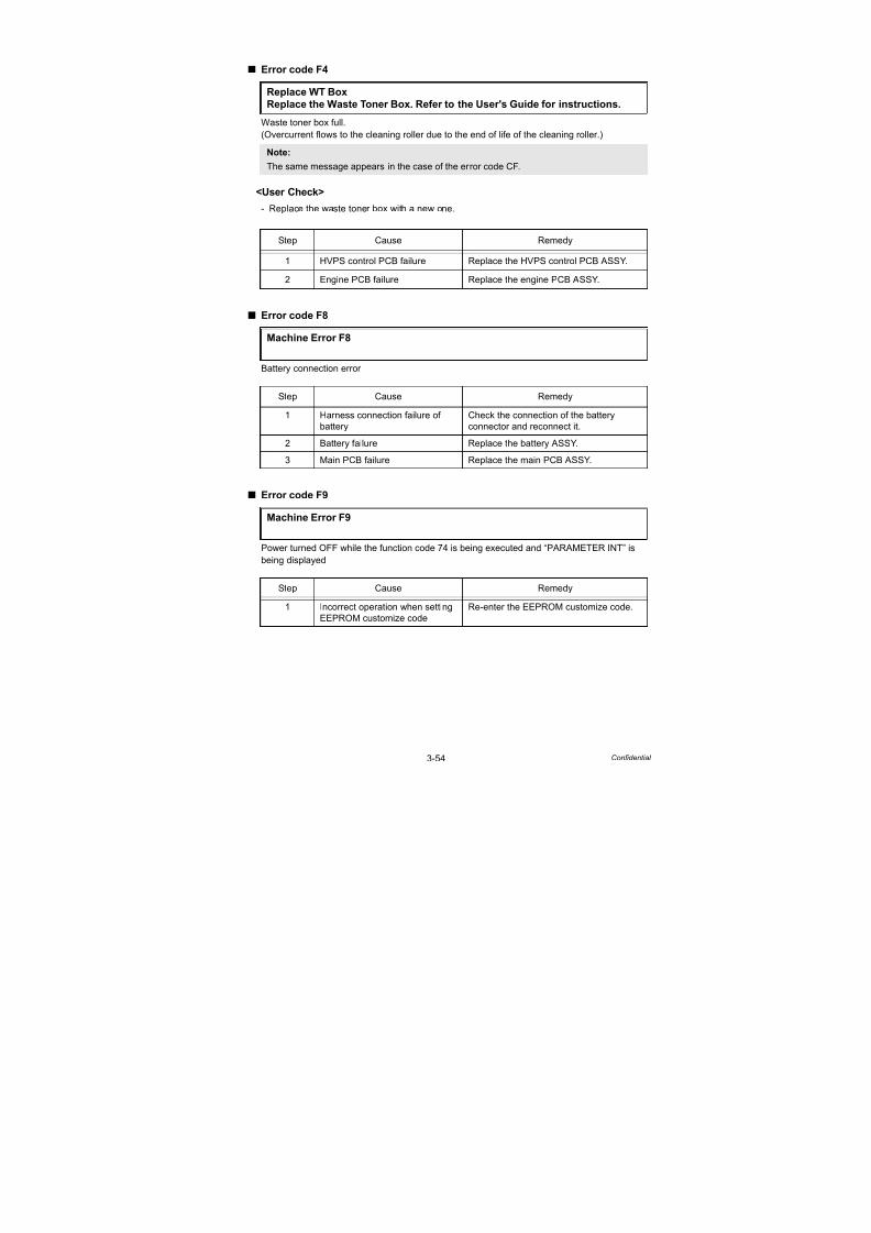
7/18/2019 Brother Mfc 9125cn 9325cw en 5694 Mfp Sm
http://slidepdf.com/reader/full/brother-mfc-9125cn-9325cw-en-5694-mfp-sm 146/597
3-54 Confidential
Error code F4
Waste toner box full.
(Overcurrent flows to the cleaning roller due to the end of life of the cleaning roller.)
<User Check>
- Replace the waste toner box with a new one.
Error code F8
Battery connection error
Error code F9
Power turned OFF while the function code 74 is being executed and “PARAMETER INT” is
being displayed
Replace WT Box
Replace the Waste Toner Box. Refer to the User's Guide for instructions.
Note:
The same message appears in the case of the error code CF.
Step Cause Remedy
1 HVPS control PCB failure Replace the HVPS control PCB ASSY.
2 Engine PCB failure Replace the engine PCB ASSY.
Machine Error F8
Step Cause Remedy
1 Harness connection failure of battery
Check the connection of the batteryconnector and reconnect it.
2 Battery failure Replace the battery ASSY.
3 Main PCB failure Replace the main PCB ASSY.
Machine Error F9
Step Cause Remedy
1 Incorrect operation when setting
EEPROM customize code
Re-enter the EEPROM customize code.
7/18/2019 Brother Mfc 9125cn 9325cw en 5694 Mfp Sm
http://slidepdf.com/reader/full/brother-mfc-9125cn-9325cw-en-5694-mfp-sm 147/597
3-55 Confidential
Error code FA (K), FB (C), FC (M), FD (Y)
The drum unit is not installed in the machine body of the product.
(No conduction on the drum electrode)
<User Check>
- Check if the drum unit of the appropriate color is installed in the machine body of the product.
No Toner
Open the Top Cover, then install Toner Cartridge. Black (K)
No Toner
Open the Top Cover, then install Toner Cartridge. Cyan (C)
No Toner
Open the Top Cover, then install Toner Cartridge. Magenta (M)
No Toner
Open the Top Cover, then install Toner Cartridge. Yellow (Y)
Step Cause Remedy
1 Bend of electrode contact of
main body
Correct the bend of the electrode contact
of the main body.
2 Dirt on electrodes of main body Clean the electrodes of the main body.
(Refer to Fig. 3-6 (P3-34))
3 HVPS control PCB failure Replace the HVPS control PCB ASSY.
4 High-voltage power supply PCB
failure
Replace the high-voltage power supply
PCB ASSY.5 Engine PCB failure Replace the engine PCB ASSY.

7/18/2019 Brother Mfc 9125cn 9325cw en 5694 Mfp Sm
http://slidepdf.com/reader/full/brother-mfc-9125cn-9325cw-en-5694-mfp-sm 148/597
3-56 Confidential
Error code FE
Detection of incorrect measurement value of density sensor sensitivity calibration
<User Check>
- Check if the 4-color drum units are properly installed in the product.
Error code FF
Overcurrent error of wireless LAN PCB
-
-
Step Cause Remedy
1 Belt unit failure Replace the belt unit.
2 Harness connection failure of
registration mark L PCB ASSY
Check the harness connection of the
registration mark L PCB ASSY and
reconnect it.
3 Registration mark relay PCB
failure
Replace the registration mark relay PCB
ASSY.
4 Main PCB failure Replace the main PCB ASSY.
5 Registration mark L PCB failure Replace the registration sensor holder
ASSY.
Unusable Device
Remove the Device. Turn the power off and back on again.
Step Cause Remedy
1 Wireless LAN PCB failure Replace the wireless LAN PCB ASSY.
2 Main PCB failure Replace the main PCB ASSY.

7/18/2019 Brother Mfc 9125cn 9325cw en 5694 Mfp Sm
http://slidepdf.com/reader/full/brother-mfc-9125cn-9325cw-en-5694-mfp-sm 149/597
3-57 Confidential
3. PAPER FEEDING PROBLEMS
Problems related to paper feeding are end user recoverable if following the User Check items.
If the same problem occurs again, follow each procedure in the order of the number described
in the Step column in the tables below.
3.1 No Feeding
<User Check>
- Check if the paper is loaded into the paper tray correctly.
- Turn over the stack of paper in the paper tray, or try rotating the paper 180° in the paper tray.
- Check if the thickness of the paper is 60 to 105 g/m2.
- Release the sleep mode or update the firmware to the latest version if the papers are not fed
from the manual feed slot when the machine is in the sleep mode.
Fig. 3-7
Step Cause Check Result Remedy
1 Paper pick-up rollerworn out
Is the paper pick-uproller worn out?
Yes Replace the rollerholder ASSY.
2 Plate gear damaged Is the plate gear damaged? Yes Replace the paper tray.
3 Registration front
actuator
malfunction
Does the registration
front actuator move
smoothly?
No Re-assemble the
registration front
actuator.
4 Disconnection of
the pick-up
solenoid harness
Is the harness of the
pick-up solenoid
disconnected?
Yes Reconnect the harness
of the pick-up solenoid.
5 Registration front/
rear sensor PCB
failure
Is the problem solved
by replacing the
registration front/rearsensor PCB ASSY?
Yes Replace the
registration front/rear
sensor PCB ASSY.
6 Pick-up solenoid
failure
Does the pick-up
solenoid move correctly?
No Replace the pick-up
solenoid.
7 Paper feed motor
failure
Is the problem solved
by replacing the paper
feed motor ASSY?
Yes Replace the paper feed
motor ASSY.
8 Engine PCB failure Is the problem solved
by replacing the engine
PCB ASSY?
Yes Replace the engine
PCB ASSY.
Engine PCB
Paper feed motor
Registration front actuator
Registration front/rear
sensor PCB
Pick-up solenoid
Plate gear
Roller holder ASSY

7/18/2019 Brother Mfc 9125cn 9325cw en 5694 Mfp Sm
http://slidepdf.com/reader/full/brother-mfc-9125cn-9325cw-en-5694-mfp-sm 150/597
3-58 Confidential
3.2 Double Feeding
<User Check>
- Check if the paper is loaded into the paper tray correctly.
- Turn over the stack of paper in the paper tray, or try rotating the paper 180° in the paper tray.
- Check if the thickness of the paper is 60 to 105 g/m2.
- Set out papers and reload them into the paper tray.
3.3 Paper Jam
<User Check>
- Check if the paper is loaded into the paper tray correctly.
- Turn over the stack of paper in the paper tray, or try rotating the paper 180° in the paper tray.
- Check if the thickness of the paper is 60 to 105 g/m2.
Paper jam in the paper tray and front section
Step Cause Check Result Remedy
1 Separation pad or
separation roller
worn out
Is the surface of the
separation pad or
separation roller worn out?
Yes Replace the paper
feeding kit.
Step Cause Check Result Remedy
1 Foreign object
around front section
Is there a foreign object
around the front section?
Yes Remove the foreign
object.
2 Belt unit
malfunction
Does the belt unit move
correctly?
No Replace the belt unit.
3 Registration front
actuator catching
on some position
Does the registration
front actuator move
smoothly?
No Re-assemble the
registration front
actuator.
4 Registration rear
actuator catching
on some position
Does the registration
rear actuator move
smoothly?
No Re-assemble the
registration rear
actuator.
5 Registration front/
rear sensor PCB
failure
Does the registration
front/rear sensor move
smoothly?
(Check it following the
procedure described in
“Function code 32”.)
No Replace the
registration front/rear
sensor PCB ASSY.

7/18/2019 Brother Mfc 9125cn 9325cw en 5694 Mfp Sm
http://slidepdf.com/reader/full/brother-mfc-9125cn-9325cw-en-5694-mfp-sm 151/597
3-59 Confidential
Paper jam in the back cover and paper eject section
3.4 Dirt on Paper
<User Check>
- Check if the paper is loaded into the paper tray correctly.
- Turn over the stack of paper in the paper tray, or try rotating the paper 180 ° in the paper tray.
- Replace the waste toner box with a new one.
Step Cause Check Result Remedy
1 Foreign object
around fuser unit
Is there a foreign object
around the fuser unit?
Yes Remove the foreign
object.
2 Paper eject rearactuator top failure
Does the paper reareject actuator top move
smoothly? Is it damaged?
No Replace the paper ejectrear actuator top.
3 Paper eject front
actuator failure
Does the paper eject front
actuator move smoothly?
Is it damaged?
No Replace the paper eject
front actuator.
4 Paper eject rear
actuator failure
Does the paper eject rear
actuator move smoothly?
Is it damaged?
No Replace the fuser unit.
5 Eject front sensor
PCB failure
Is the problem solved by
replacing the eject front
sensor PCB ASSY?
Yes Replace the eject front
sensor PCB ASSY.
6 Eject rear sensor
PCB failure
Is the problem solved by
replacing the eject rear
sensor PCB ASSY?
Yes Replace the eject rear
sensor PCB ASSY.
Step Cause Check Result Remedy
1 Fuser unit dirty Is there dirt around the
entrance of the fuser
unit?
Yes Clean the entrance of
the fuser unit.
Is the pressure roller
dirty?
Yes Clean the pressure
roller.
2 Dirt in the paperfeed system
Is the paper tray or feedsystem on the drum unit
dirty with toner?
Yes Wipe dirt off.
3 Belt unit dirty Does dirt on the paper
disappear after
replacing the belt unit
with a new one?
Yes Replace the belt unit.
4 Waste toner
sensor failure
Is the waste toner box
full of toner?
No Replace the waste toner
sensor.
5 Main PCB failure Is the problem solved
after replacing the main
PCB ASSY?
Yes Replace the main PCB
ASSY.

7/18/2019 Brother Mfc 9125cn 9325cw en 5694 Mfp Sm
http://slidepdf.com/reader/full/brother-mfc-9125cn-9325cw-en-5694-mfp-sm 152/597
3-60 Confidential
3.5 Wrinkles on Paper
<User Check>
- Check if the paper is loaded into the paper tray correctly.
- Turn over the stack of paper in the paper tray, or try rotating the paper 180 ° in the paper tray.
- Check if the thickness of the paper is 60 to 105 g/m2.
3.6 Curl of Paper
Fig. 3-8
Step Cause Check Result Remedy
1 Fuser unit failure Do wrinkles on the
paper disappear after
replacing the fuser unit
with a new one?
Yes Replace the fuser unit.
<User Check>
- Change the curl improvement mode setting of the driver.
- Switch the delivery roller switch lever.
Note:
Be sure not set the curl improvement mode of the driver and switch to the delivery roller switch lever at the same time because it might worsen the level of curl.
Delivery roller switch lever
Delivery roller switch lever
<Left side>

7/18/2019 Brother Mfc 9125cn 9325cw en 5694 Mfp Sm
http://slidepdf.com/reader/full/brother-mfc-9125cn-9325cw-en-5694-mfp-sm 153/597
3-61 Confidential
4. PRINT IMAGE DEFECT FROM PC/USB/FAX
RECEPTION TROUBLESHOOTING
4.1 Image Defect Examples
Fig. 3-9
Light on the whole page One color is light Faulty registration Dark
White horizontal stripes on one color image
Completely blank Image distortion All one color
Dirt on the back of paper Vertical streaks Vertical streaks in a light background
Horizontal stripes White vertical streaks on one color image
Poor fixing
Faint print
White spots on one color image One color spots or dirt
One color band Downward fogging of solid color Horizontal lines
Vertical streaks in a dark background
Ghost Color misregistration Fogging Unstable color density Hollow print

7/18/2019 Brother Mfc 9125cn 9325cw en 5694 Mfp Sm
http://slidepdf.com/reader/full/brother-mfc-9125cn-9325cw-en-5694-mfp-sm 154/597
3-62 Confidential
4.2 Pitch Indicated in Roller Image
Image defects which occur periodically may be caused by a failure of the roller. By referring to
the table below, specify the cause based on the pitch indicated in the image of each roller.
4.3 Troubleshooting Image Defect
Image defect related problems are user recoverable if following the User Check items. If the
same problem occurs, follow each procedure in the order of the number described in the Step
column in the tables below.
Light on the whole page
No. Parts name The pitch which appears in the image
1 Develop roller 31 mm
2 Exposure drum 94 mm
3 Heat roller in the fuser unit 78 mm
4 Pressure roller in the fuser unit 78 mm
<User Check>
- Check the machine’s environment. High temperature and high humidity
or low temperature and low humidity conditions can cause this problem.
- If the whole page is light, toner save mode may be on. Turn off the toner
save mode.
- Replace the toner cartridge or drum unit with a new one.
- Adjust the color density from the control panel cover ASSY.
- Leave the machine for a while as the power remains ON.
Step Cause Check Result Remedy
1 HVPS control PCB
failure
Is the problem solved
after replacing the HVPS
control PCB ASSY?
Yes Replace the HVPS
control PCB ASSY.
2 High-voltage power
supply PCB failure
Is the problem solved
after replacing the
high-voltage power
supply PCB ASSY?
Yes Replace the
high-voltage power
supply PCB ASSY.
3 Engine PCB failure Is the problem solved
after replacing the
engine PCB ASSY?
Yes Replace the engine
PCB ASSY.
4 Main PCB failure Is the problem solved
after replacing the main
PCB ASSY?
Yes Replace the main PCB
ASSY.
5 LED head control
PCB failure
Is the problem solved
after replacing the LED
head control PCB ASSY?
Yes Replace the LED head
control PCB ASSY.
6 LED ASSY failure Is the problem solved after
replacing the LED ASSY?
Yes Replace the LED ASSY.
7 Registration mark L
PCB failure
Is the problem solved
after replacing the
registration sensorholder ASSY?
Yes Replace the
registration sensor
holder ASSY.

7/18/2019 Brother Mfc 9125cn 9325cw en 5694 Mfp Sm
http://slidepdf.com/reader/full/brother-mfc-9125cn-9325cw-en-5694-mfp-sm 155/597

7/18/2019 Brother Mfc 9125cn 9325cw en 5694 Mfp Sm
http://slidepdf.com/reader/full/brother-mfc-9125cn-9325cw-en-5694-mfp-sm 156/597
3-64 Confidential
Faulty registration
8 HVPS control PCB
failure
Is the problem solved
after replacing the
HVPS control PCB
ASSY?
Yes Replace the HVPS
control PCB ASSY.
9 High-voltage powersupply PCB failure
Is the problem solvedafter replacing the
high-voltage power
supply PCB ASSY?
Yes Replace thehigh-voltage power
supply PCB ASSY.
10 LED head control
PCB failure
Is the problem solved
after replacing the LED
head control PCB
ASSY?
Yes Replace the LED head
control PCB ASSY.
11 Main PCB failure Is the problem solved
after replacing the main
PCB ASSY.
Yes Replace the main PCB
ASSY.
Step Cause Check Result Remedy
1 Registration rear
actuator catching
on some position
Does the registration
rear actuator move
smoothly?
No Correct catching of the
registration rear
actuator.
2 HVPS control PCB
failure
Is the problem solved
after replacing the HVPS
control PCB ASSY?
Yes Replace the HVPS
control PCB ASSY.
3 Main PCB failure Is the problem solved
after replacing the main
PCB ASSY?
Yes Replace the main PCB
ASSY.
Step Cause Check Result Remedy
7/18/2019 Brother Mfc 9125cn 9325cw en 5694 Mfp Sm
http://slidepdf.com/reader/full/brother-mfc-9125cn-9325cw-en-5694-mfp-sm 157/597
3-65 Confidential
Dark
<User Check>
- Check the machine’s environment. High temperature and high humidity
or low temperature and low humidity conditions can cause this problem.
- Clean the corona wire.
- Replace the toner cartridge or drum unit with a new one.
- Adjust the color density from the control panel cover ASSY.
Step Cause Check Result Remedy
1 Corona wire
conduction failure
Are the electrodes on
the drum unit and
machine body dirty?
Yes Clean both electrodes.
(Refer to Fig. 3-3
(P3-33) and Fig. 3-6
(P3-34))
2 Dirt on belt unit
electrode
Are the electrodes on
the belt unit and
machine body dirty?
Yes Clean both electrodes.
(Refer to Fig. 3-4
(P3-33) and Fig. 3-6(P3-34))
3 HVPS control PCB
failure
Is the problem solved
after replacing the HVPS
control PCB ASSY?
Yes Replace the HVPS
control PCB ASSY.
4 High-voltage power
supply PCB failure
Is the problem solved
after replacing the
high-voltage power
supply PCB ASSY?
Yes Replace the
high-voltage power
supply PCB ASSY.
5 Engine PCB failure Is the problem solved
after replacing theengine PCB ASSY?
Yes Replace the engine
PCB ASSY.
6 Main PCB failure Is the problem solved
after replacing the main
PCB ASSY?
Yes Replace the main PCB
ASSY.
7 LED head control
PCB failure
Is the problem solved
after replacing the LED
head control PCB
ASSY?
Yes Replace the LED head
control PCB ASSY.
8 Registration mark L
PCB failure
Is the problem solved
after replacing the
registration sensor
holder ASSY?
Yes Replace the
registration sensor
holder ASSY.
9 Toner/new
sensor PCB failure
Is the problem solved
after replacing the
toner/new sensor PCB
ASSY?
Yes Replace the toner/new
sensor PCB ASSY.
7/18/2019 Brother Mfc 9125cn 9325cw en 5694 Mfp Sm
http://slidepdf.com/reader/full/brother-mfc-9125cn-9325cw-en-5694-mfp-sm 158/597
3-66 Confidential
Poor fixing
<User Check>
- Open and close the top cover and make print again.
- Adjust the color density from the control panel cover ASSY.
- Check the machine’s environment. High temperature and high humidity
or low temperature and low humidity conditions can cause this problem.
- Replace the belt unit with a new one.
- Replace the drum unit with a new one.
- Replace the toner cartridge with a new one.
Memo:
You can check this image defect with the function code 71.
(Refer to “1.4.21 Color test pattern (Function code 71)” in Chapter 7)
Step Cause Check Result Remedy
1 Lifting of LED
ASSY
Is printing of the LED
ASSY test pattern
correctly done in
“Function code 68”?
No Re-assemble the
LED ASSY.
2 Fuser unit failure Is the problem solved
after replacing the fuser
unit?
Yes Replace the fuser unit.
3 Low-voltage power
supply PCB failure
Is the problem solved
after replacing the
low-voltage power
supply PCB ASSY?
Yes Replace the
low-voltage power
supply PCB ASSY.
4 HVPS control PCB
failure
Is the problem solved
after replacing the HVPS
control PCB ASSY?
Yes Replace the HVPS
control PCB ASSY.
5 High-voltage power
supply PCB failure
Is the problem solved
after replacing the
high-voltage power
supply PCB ASSY?
Yes Replace the
high-voltage power
supply PCB ASSY.
6 Engine PCB failure Is the problem solved
after replacing the
engine PCB ASSY?
Yes Replace the engine
PCB ASSY.
7 Toner/new
sensor PCB failure
Is the problem solved
after replacing the
toner/new sensor PCB
ASSY?
Yes Replace the toner/new
sensor PCB ASSY.
8 Main PCB failure Is the problem solved
after replacing the main
PCB?
Yes Replace the main PCB
ASSY.

7/18/2019 Brother Mfc 9125cn 9325cw en 5694 Mfp Sm
http://slidepdf.com/reader/full/brother-mfc-9125cn-9325cw-en-5694-mfp-sm 159/597
3-67 Confidential
Completely blank
Image distortion
<User Check>
- Replace the belt unit with a new one.
- Replace the toner cartridge or drum unit with a new one.
Step Cause Check Result Remedy
1 Developing bias
voltage conduction
failure
Are the electrodes on the
drum unit and machine
body dirty?
Yes Clean both electrodes.
(Refer to Fig. 3-3 (P3-33)
and Fig. 3-6 (P3-34))
2 Dirt on develop roller
electrode
Are the electrodes on the
develop roller and
machine body dirty?
Yes Clean both electrodes.
(Refer to Fig. 3-3 (P3-33)
and Fig. 3-6 (P3-34))
3 LED array FFCconnection failure
Is the LED array FFCconnected securely?
No Reconnect the LED arrayFFC.
4 LED ASSY failure Is the problem solved after
replacing the LED ASSY?
Yes Replace the LED ASSY.
5 HVPS control PCB
failure
Is the problem solved after
replacing the HVPS
control PCB ASSY?
Yes Replace the HVPS
control PCB ASSY.
6 High-voltage power
supply PCB failure
Is the problem solved after
replacing the high-voltage
power supply PCB ASSY?
Yes Replace the high-voltage
power supply PCB ASSY.
7 LED head control
PCB failure
Is the problem solved after
replacing the LED head
control PCB ASSY?
Yes Replace the LED head
control PCB ASSY.
8 Main PCB failure Is the problem solved after
replacing the main PCB
ASSY?
Yes Replace the main PCB
ASSY.
<User Check>
- Replace the belt unit with a new one.
Step Cause Check Result Remedy
1 LED head control
PCB failure
Is the problem solved
after replacing the LED
head control PCB ASSY?
Yes Replace the LED head
control PCB ASSY.
2 Main PCB failure Is the problem solved
after replacing the mainPCB ASSY?
Yes Replace the main PCB
ASSY.

7/18/2019 Brother Mfc 9125cn 9325cw en 5694 Mfp Sm
http://slidepdf.com/reader/full/brother-mfc-9125cn-9325cw-en-5694-mfp-sm 160/597
3-68 Confidential
All one color
Memo:
You can check this image defect with the function code 71.
(Refer to “1.4.21 Color test pattern (Function code 71)” in Chapter 7)
Step Cause Check Result Remedy
1 Corona wire
failure
Are the electrodes on
the drum unit of the
appropriate color andmachine body dirty?
Yes Clean both electrodes.
(Refer to Fig. 3-3
(P3-33) and Fig. 3-6(P3-34))
2 Is the corona wire
damaged?
Yes Replace the drum unit.
3 HVPS control PCB
failure
Is the problem solved
after replacing the HVPS
control PCB ASSY?
Yes Replace the HVPS
control PCB ASSY.
4 High-voltage power
supply PCB failure
Is the problem solved
after replacing the
high-voltage power
supply PCB ASSY?
Yes Replace the
high-voltage power
supply PCB ASSY.
5 LED ASSY failure Is the problem solved
after replacing the LED
ASSY?
Yes Replace the LED ASSY.
6 LED head control
PCB failure
Is the problem solved
after replacing the LED
head control PCB
ASSY?
Yes Replace the LED head
control PCB ASSY.
7 Main PCB failure Is the problem solved
after replacing the main
PCB ASSY?
Yes Replace the main PCB
ASSY.
7/18/2019 Brother Mfc 9125cn 9325cw en 5694 Mfp Sm
http://slidepdf.com/reader/full/brother-mfc-9125cn-9325cw-en-5694-mfp-sm 161/597
3-69 Confidential
Dirt on the back of paper
<User Check>
- Replace the waste toner box with a new one.
- Replace the belt unit with a new one.
Step Cause Check Result Remedy
1 Fuser unit dirty Is the pressure roller
dirty?
Yes Print approximate 10
pages.
Is the fuser unit dirty? No Replace the fuser unit.
2 Dirt in the paper
feed system
Is the paper tray or feed
system on the drum unit
dirty with toner?
Yes Wipe dirt off.
3 Waste toner
sensor failure
Is the waste toner box
full of toner?
Yes Replace the waste toner
sensor.
4 HVPS control PCB
failure
Is the problem solved
after replacing the HVPS
control PCB ASSY?
Yes Replace the HVPS
control PCB ASSY.
5 High-voltage power
supply PCB failure
Is the problem solved
after replacing the
high-voltage power
supply PCB ASSY?
Yes Replace the
high-voltage power
supply PCB ASSY.
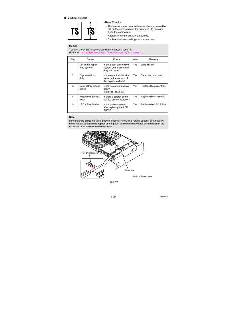
7/18/2019 Brother Mfc 9125cn 9325cw en 5694 Mfp Sm
http://slidepdf.com/reader/full/brother-mfc-9125cn-9325cw-en-5694-mfp-sm 162/597
3-70 Confidential
Vertical streaks
Fig. 3-10
<User Check>
- This problem may occur with noise which is caused by
dirt on the corona wire in the drum unit. In this case,
clean the corona wire.
- Replace the drum unit with a new one.- Replace the toner cartridge with a new one.
Memo:
You can check this image defect with the function code 71.
(Refer to “1.4.21 Color test pattern (Function code 71)” in Chapter 7)
Step Cause Check Result Remedy
1 Dirt in the paper
feed system
Is the paper tray or feed
system on the drum unit
dirty with toner?
Yes Wipe dirt off.
2 Exposure drum
dirty
Is there vertical dirt with
toner on the surface of
the exposure drum?
Yes Clean the drum unit.
3 Bend of tray ground
spring
Is the tray ground spring
bent?
(Refer to Fig. 3-10)
Yes Replace the paper tray.
4 Scratch on the heat
roller
Is there a scratch on the
surface of the heat roller?
Yes Replace the fuser unit.
5 LED ASSY failure Is the problem solved
after replacing the LED ASSY?
Yes Replace the LED ASSY.
Note:
If the machine prints the same pattern, especially including vertical streaks, continuously,
black vertical streaks may appear on the paper since the electrostatic performance of the
exposure drum is decreased temporally.
Paper tray
Tray ground spring
<Bottom of paper tray>
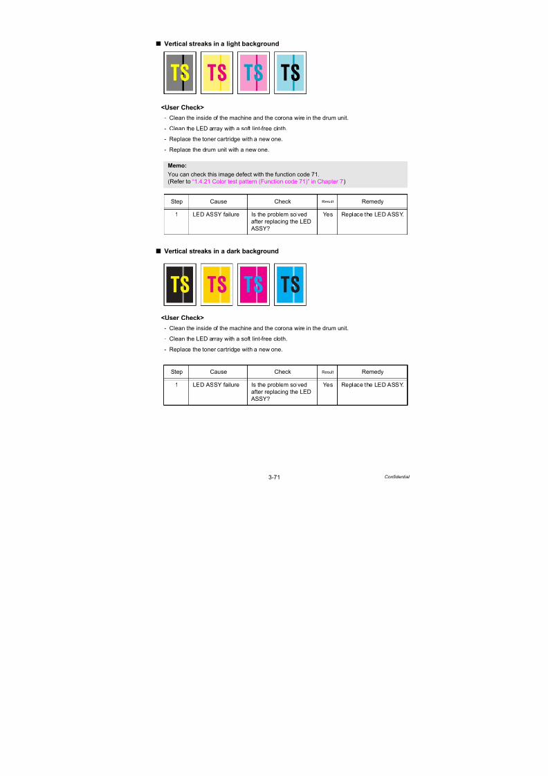
7/18/2019 Brother Mfc 9125cn 9325cw en 5694 Mfp Sm
http://slidepdf.com/reader/full/brother-mfc-9125cn-9325cw-en-5694-mfp-sm 163/597
3-71 Confidential
Vertical streaks in a light background
<User Check>
- Clean the inside of the machine and the corona wire in the drum unit.
- Clean the LED array with a soft lint-free cloth.
- Replace the toner cartridge with a new one.
- Replace the drum unit with a new one.
Vertical streaks in a dark background
<User Check>
- Clean the inside of the machine and the corona wire in the drum unit.
- Clean the LED array with a soft lint-free cloth.
- Replace the toner cartridge with a new one.
Memo:
You can check this image defect with the function code 71.(Refer to “1.4.21 Color test pattern (Function code 71)” in Chapter 7)
Step Cause Check Result Remedy
1 LED ASSY failure Is the problem solved
after replacing the LED
ASSY?
Yes Replace the LED ASSY.
Step Cause Check Result Remedy
1 LED ASSY failure Is the problem solved
after replacing the LED
ASSY?
Yes Replace the LED ASSY.

7/18/2019 Brother Mfc 9125cn 9325cw en 5694 Mfp Sm
http://slidepdf.com/reader/full/brother-mfc-9125cn-9325cw-en-5694-mfp-sm 164/597
3-72 Confidential
Horizontal stripes
<User Check>
- Clean the inside of the machine and the corona wire in the drum unit.
- Replace the drum unit with a new one.
Step Cause Check Result Remedy
1 Dirt on the charged
electrode
Are the electrodes on
the drum unit and
machine body dirty?
Yes Clean both electrodes.
(Refer to Fig. 3-3
(P3-33) and Fig. 3-6
(P3-34))
2 Bend of tray ground
spring
Is the tray ground spring
bent? (Refer to
Fig. 3-10 (P3-70))
Yes Replace the paper tray.
3 Toner attached on
the develop roller
Are the horizontal
stripes at 31 mm
(develop roller
circumference)
intervals?
Yes This problem will
disappear by printing
approximate 10 pages.
If the same problem
occurs, replace the
toner cartridge.
4 Scratch on the heat
roller
Are the horizontal
stripes at 78 mm (heat
roller circumference)
intervals?
Yes Replace the fuser unit.
5 HVPS control PCBfailure
Is the problem solvedafter replacing the HVPS
control PCB ASSY?
Yes Replace the HVPScontrol PCB ASSY.

7/18/2019 Brother Mfc 9125cn 9325cw en 5694 Mfp Sm
http://slidepdf.com/reader/full/brother-mfc-9125cn-9325cw-en-5694-mfp-sm 165/597
3-73 Confidential
White vertical streaks on one color image
<User Check>
- Check if there is no dust in the gap between the toner cartridge and drum frame.
- Clean the relevant color LED array on which color loss occurs with a soft lint-free cloth.
- Replace the toner cartridge with a new one.
- Check the machine’s environment. High temperature and high humidity or low temperature
and low humidity conditions can cause this problem.
- Damp (wet) paper might be used. Try to change to freshly unpacked paper.
- Replace the drum unit with a new one.
Step Cause Check Result Remedy
1 Condensation Has condensation
occurred inside the
machine?
Yes Try to print several
pages or leave the
machine 2 hours to
allow it to reach room
temperature.
2 LED array failure Is the problem solved
after replacing the LED
ASSY?
Yes Replace the LED ASSY.

7/18/2019 Brother Mfc 9125cn 9325cw en 5694 Mfp Sm
http://slidepdf.com/reader/full/brother-mfc-9125cn-9325cw-en-5694-mfp-sm 166/597
3-74 Confidential
White horizontal stripes on one color image
<User Check>
- The problem may disappear by itself. Try printing multiple pages to clear this problem
especially if the machine has not been used for a long time.
- Replace the toner cartridge with a new one.
- The drum unit may be damaged. Replace the drum unit with a new one.
Faint print
Step Cause Check Result Remedy
1 HVPS control PCB
failure
Is the problem solved
after replacing the HVPS
control PCB ASSY?
Yes Replace the HVPS
control PCB ASSY.
2 High-voltage power
supply PCB failure
Is the problem solved
after replacing the
high-voltage power
supply PCB ASSY?
Yes Replace the
high-voltage power
supply PCB ASSY.
3 Engine PCB failure Is the problem solved
after replacing the
engine PCB ASSY?
Yes Replace the engine
PCB ASSY.
<User Check>
- Open and close the top cover and make print again.
- Check that the machine is installed on a level surface.
- Replace the toner cartridge with a new one.
- Clean the LED array with a soft lint-free cloth.
Step Cause Check Result Remedy
1 Lifting of LED ASSY Is printing of the LED
ASSY test pattern
correctly done in
“Function code 68”?
Yes Re-assemble the LED
ASSY.
2 Toner/new
sensor PCB failure
Is the “Replace Toner”
message indicated on
the LCD when replacing
the toner cartridge with
the one which has
reached the end of life?
No Replace the toner/new
sensor PCB ASSY.
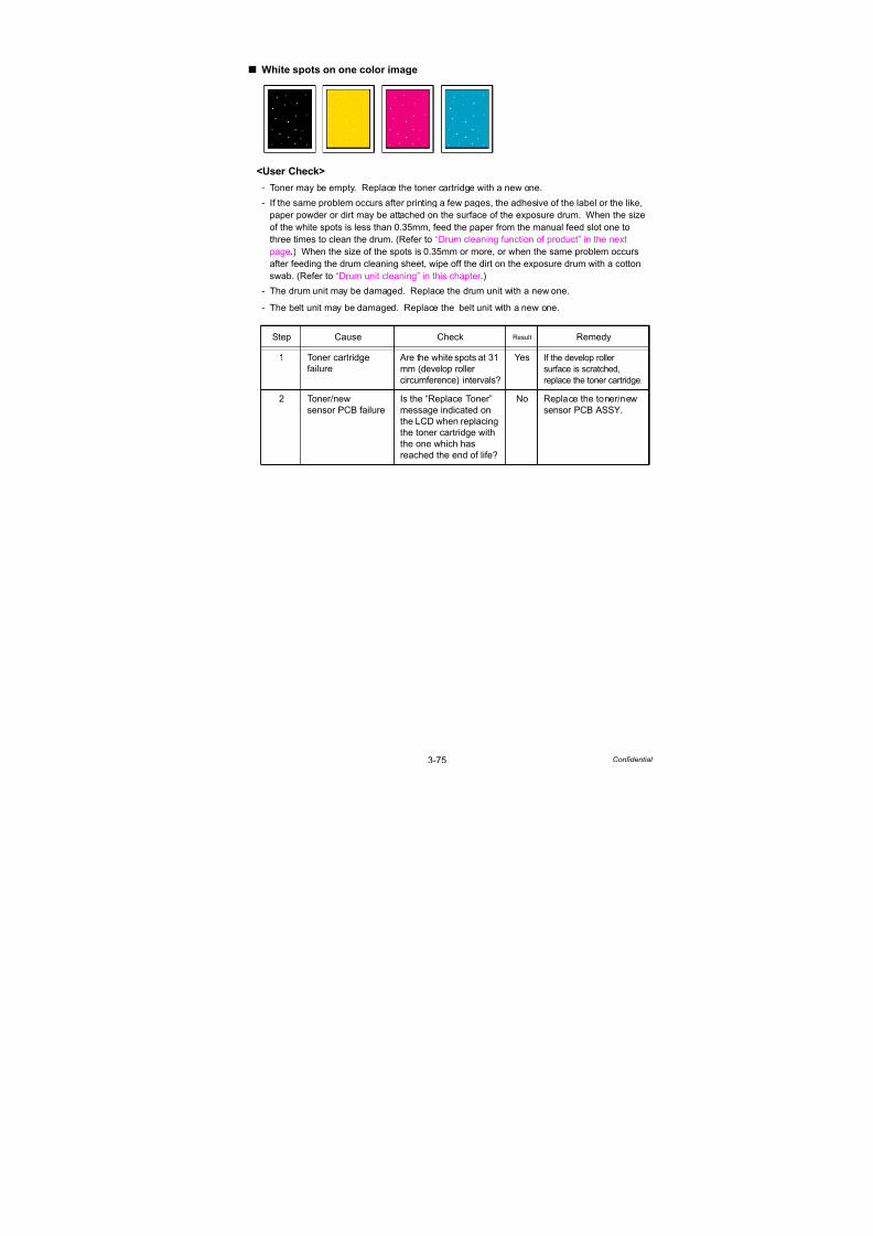
7/18/2019 Brother Mfc 9125cn 9325cw en 5694 Mfp Sm
http://slidepdf.com/reader/full/brother-mfc-9125cn-9325cw-en-5694-mfp-sm 167/597
3-75 Confidential
White spots on one color image
<User Check>
- Toner may be empty. Replace the toner cartridge with a new one.
- If the same problem occurs after printing a few pages, the adhesive of the label or the like,
paper powder or dirt may be attached on the surface of the exposure drum. When the size
of the white spots is less than 0.35mm, feed the paper from the manual feed slot one to
three times to clean the drum. (Refer to “Drum cleaning function of product” in the next
page.) When the size of the spots is 0.35mm or more, or when the same problem occurs
after feeding the drum cleaning sheet, wipe off the dirt on the exposure drum with a cotton
swab. (Refer to “Drum unit cleaning” in this chapter .)- The drum unit may be damaged. Replace the drum unit with a new one.
- The belt unit may be damaged. Replace the belt unit with a new one.
Step Cause Check Result Remedy
1 Toner cartridge
failure
Are the white spots at 31
mm (develop roller
circumference) intervals?
Yes If the develop roller
surface is scratched,
replace the toner cartridge.
2 Toner/new
sensor PCB failure
Is the “Replace Toner”
message indicated on
the LCD when replacing
the toner cartridge with
the one which has
reached the end of life?
No Replace the toner/new
sensor PCB ASSY.

7/18/2019 Brother Mfc 9125cn 9325cw en 5694 Mfp Sm
http://slidepdf.com/reader/full/brother-mfc-9125cn-9325cw-en-5694-mfp-sm 168/597
3-76 Confidential
<Drum cleaning function of product>
(1) Open the manual feed slot cover.
Fig. 3-11
(2) Using both hands, slide the manual feed slot paper guides to the width of the paper that
you are going to use.
Fig. 3-12
(3) Using both hands, put one piece of paper in the manual feed slot until the front edge of
the paper touches the paper feed roller. Wait until the machine automatically feeds the
paper. When you feel the machine pull in the paper, let go.
Fig. 3-13
Note:
If there is any problem in the print quality, be sure to clean the drum unit in accordance with
“Drum cleaning function of product” provided below.
If the problem still persists, be sure to clean the drum unit manually in accordance with
“Drum unit cleaning” in this chapter .
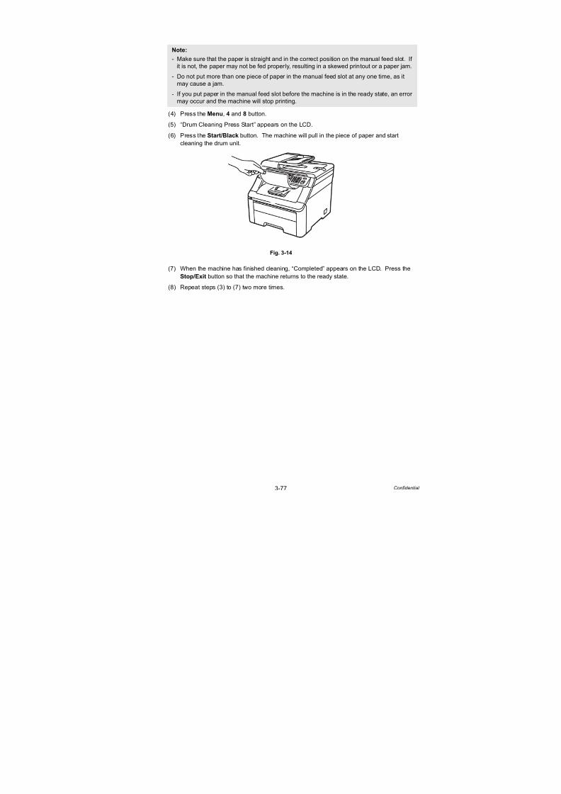
7/18/2019 Brother Mfc 9125cn 9325cw en 5694 Mfp Sm
http://slidepdf.com/reader/full/brother-mfc-9125cn-9325cw-en-5694-mfp-sm 169/597
3-77 Confidential
(4) Press the Menu, 4 and 8 button.
(5) “Drum Cleaning Press Start” appears on the LCD.
(6) Press the Start/Black button. The machine will pull in the piece of paper and start
cleaning the drum unit.
Fig. 3-14
(7) When the machine has finished cleaning, “Completed” appears on the LCD. Press theStop/Exit button so that the machine returns to the ready state.
(8) Repeat steps (3) to (7) two more times.
Note:
- Make sure that the paper is straight and in the correct position on the manual feed slot. If
it is not, the paper may not be fed properly, resulting in a skewed printout or a paper jam.
- Do not put more than one piece of paper in the manual feed slot at any one time, as it
may cause a jam.
- If you put paper in the manual feed slot before the machine is in the ready state, an error
may occur and the machine will stop printing.

7/18/2019 Brother Mfc 9125cn 9325cw en 5694 Mfp Sm
http://slidepdf.com/reader/full/brother-mfc-9125cn-9325cw-en-5694-mfp-sm 170/597
3-78 Confidential
<Drum unit cleaning>
(1) Pull the drum unit out of the machine and take all the toner cartridges out of the drum unit.
(2) See the print sample to identify the color causing the problem. The color of the spots is
the color of the drum you should clean. For example, if the spots are cyan, you should
clean the drum for cyan. Put the print sample in front of the drum, and find the exact
position of the poor print.
Fig. 3-15
(3) Turn the drum unit gear to the direction of the arrow as shown in the figure below by hand
to find smears on the drum while looking at the surface of the drum “1”.
Fig. 3-16
(4) When you have found the mark on the drum that matches the print sample, wipe the
surface of the drum gently with a cotton swab until the dust or paper powder on the
surface comes off.
Fig. 3-17
Note:
We recommend that you place the drum unit on a clean, flat surface with a piece of
disposable paper underneath it in case you accidentally spill or scatter toner.
Note:
DO NOT clean the surface of the photosensitive drum with a sharp object.
“1”

7/18/2019 Brother Mfc 9125cn 9325cw en 5694 Mfp Sm
http://slidepdf.com/reader/full/brother-mfc-9125cn-9325cw-en-5694-mfp-sm 171/597
3-79 Confidential
One color spots or dirt
<User Check>
- Damp (wet) paper might be used. Try to changing to freshly unopened paper.
- Toner may be empty. Replace the toner cartridge with a new one.
- If the same problem occurs after printing a few pages, the adhesive of a label or the like,
paper powder or dirt may be attached on the surface of the exposure drum. Feed the paper
from the manual feed slot one to three times to clean the drum. (Refer to “Drum cleaning
function of product” in this chapter .)
When the same problem occurs after feeding the drum cleaning sheet, wipe off the dirt on
the exposure drum with a cotton swab. (Refer to “Drum unit cleaning” in the previous pages.)
- The drum unit may be damaged. Replace the drum unit with a new one.
- The belt unit may be damaged. Replace the belt unit with a new one.
Step Cause Check Result Remedy
1 Fuser unit failure Are the spots at 78 mm
(heat roller
circumference)
intervals?
Yes Replace the fuser unit.
2 Toner/newsensor PCB failure
Is the “Replace Toner”message indicated on
the LCD when replacing
the toner cartridge with
the one which has
reached the end of life?
Yes Replace the toner/newsensor PCB ASSY.

7/18/2019 Brother Mfc 9125cn 9325cw en 5694 Mfp Sm
http://slidepdf.com/reader/full/brother-mfc-9125cn-9325cw-en-5694-mfp-sm 172/597
3-80 Confidential
One color band
<User Check>
- Clean the inside of the machine and the corona wire in the drum unit. If the same problem
occurs after cleaning, replace the drum unit with a new one.
- The paper tray ground terminal provided in the machine body may be dirty. Clean the
contact with a dry cloth.
Downward fogging of solid color
<User Check>
- Toner may be empty. Replace the toner cartridge with a new one.
Step Cause Check Result Remedy
1 HVPS control PCB
failure
Is the problem solved
after replacing the HVPS
control PCB ASSY?
Yes Replace the HVPS
control PCB ASSY.
2 High-voltage power
supply PCB failure
Is the problem solved
after replacing the
high-voltage power
supply PCB ASSY?
Yes Replace the
high-voltage power
supply PCB ASSY.
3 Engine PCB failure Is the problem solved
after replacing the
engine PCB ASSY?
Yes Replace the engine
PCB ASSY.
4 Main PCB failure Is the problem solved
after replacing the
main PCB ASSY?
Yes Replace the main PCB
ASSY.

7/18/2019 Brother Mfc 9125cn 9325cw en 5694 Mfp Sm
http://slidepdf.com/reader/full/brother-mfc-9125cn-9325cw-en-5694-mfp-sm 173/597
3-81 Confidential
Horizontal lines
<User Check>
- The paper tray ground terminal provided in the machine
body may be dirty. Clean the contact with a dry cloth.
- Replace the drum unit with a new one.
- Replace the toner cartridge with a new one.
Step Cause Check Result Remedy
1 Dirt on charged
electrode
Are the electrodes on
the drum unit and
machine body dirty?
Yes Clean both electrodes.
(Refer to Fig. 3-3 (P3-33)
and Fig. 3-6 (P3-34))
2 Paper tray ground
terminal provided
in machine body
Is the paper tray ground
terminal bent, which is
provided in the machine
body?
Yes Correct bending of
paper tray ground
terminal.
3 Toner attached on
the develop roller
Are the horizontal lines
at 31 mm (develop roller
circumference)
intervals?
Yes This symptom might
disappear after making
approximate 10 prints.
4 Scratch on the heat
roller
Are the horizontal lines
at 78 mm (heat roller
circumference)
intervals?
Yes Replace the fuser unit.
5 HVPS control PCB
failure
Is the problem solved
after replacing the HVPS
control PCB ASSY?
Yes Replace the HVPS
control PCB ASSY.
6 High-voltage power
supply PCB failure
Is the problem solved
after replacing the
high-voltage power
supply PCB ASSY.
Yes Replace the
high-voltage power
supply PCB ASSY.
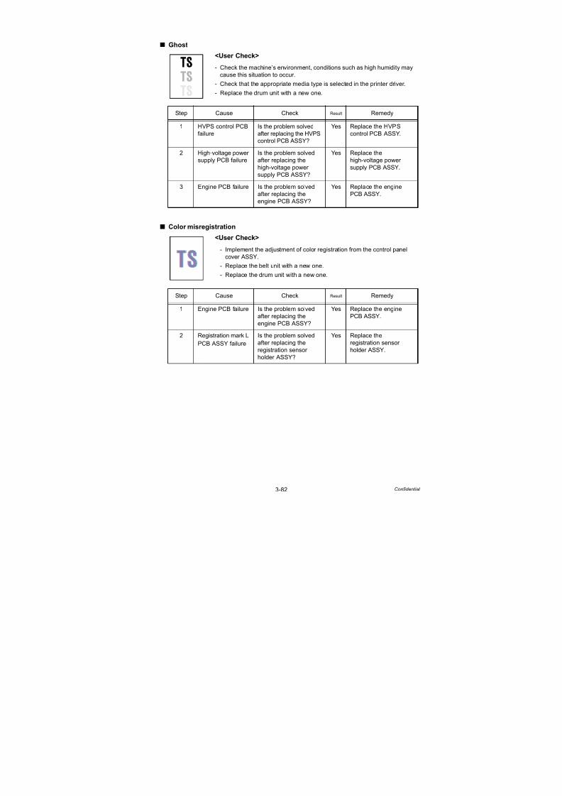
7/18/2019 Brother Mfc 9125cn 9325cw en 5694 Mfp Sm
http://slidepdf.com/reader/full/brother-mfc-9125cn-9325cw-en-5694-mfp-sm 174/597
3-82 Confidential
Ghost
Color misregistration
<User Check>
- Check the machine’s environment, conditions such as high humidity may
cause this situation to occur.
- Check that the appropriate media type is selected in the printer driver.
- Replace the drum unit with a new one.
Step Cause Check Result Remedy
1 HVPS control PCB
failure
Is the problem solved
after replacing the HVPS
control PCB ASSY?
Yes Replace the HVPS
control PCB ASSY.
2 High-voltage power
supply PCB failure
Is the problem solved
after replacing the
high-voltage power
supply PCB ASSY?
Yes Replace the
high-voltage power
supply PCB ASSY.
3 Engine PCB failure Is the problem solved
after replacing the
engine PCB ASSY?
Yes Replace the engine
PCB ASSY.
<User Check>
- Implement the adjustment of color registration from the control panel
cover ASSY.
- Replace the belt unit with a new one.- Replace the drum unit with a new one.
Step Cause Check Result Remedy
1 Engine PCB failure Is the problem solved
after replacing the
engine PCB ASSY?
Yes Replace the engine
PCB ASSY.
2 Registration mark L
PCB ASSY failure
Is the problem solved
after replacing the
registration sensor
holder ASSY?
Yes Replace the
registration sensor
holder ASSY.

7/18/2019 Brother Mfc 9125cn 9325cw en 5694 Mfp Sm
http://slidepdf.com/reader/full/brother-mfc-9125cn-9325cw-en-5694-mfp-sm 175/597
3-83 Confidential
Fogging
<User Check>
- Replace the toner cartridge with a new one.
- Replace the drum unit with a new one.
- Do not use acid paper.
Step Cause Check Result Remedy
1 Toner/new
sensor PCB failure
Is the toner sensor
performed normally by
following the procedure
described in “Function
code 32” to check?
No Replace the toner/new
sensor PCB ASSY.
2 HVPS control PCB
failure
Is the problem solved
after replacing the HVPS
control PCB ASSY?
Yes Replace the HVPS
control PCB ASSY.
3 High-voltage power
supply PCB failure
Is the problem solved
after replacing the
high-voltage power
supply PCB ASSY?
Yes Replace the
high-voltage power
supply PCB ASSY.
4 Engine PCB failure Is the problem solved
after replacing the
engine PCB ASSY?
Yes Replace the engine
PCB ASSY.
Note:
This problem often occurs when the drum unit or toner cartridge is nearly at the end of life.

7/18/2019 Brother Mfc 9125cn 9325cw en 5694 Mfp Sm
http://slidepdf.com/reader/full/brother-mfc-9125cn-9325cw-en-5694-mfp-sm 176/597
3-84 Confidential
Unstable color density
<User Check>
- Make a print on a different type of paper.
- Replace the belt unit with a new one.
- Replace the drum unit with a new one.- Replace the waste toner box with a new one.
- Replace the toner cartridge with a new one.
Step Cause Check Result Remedy
1 Drum unit
conduction failure
Are the electrodes on
the drum unit and
machine body dirty?
Yes Clean both electrodes.
(Refer to Fig. 3-3 (P3-33)
and Fig. 3-6 (P3-34))
2 Toner cartridge
conduction failure
Are the electrodes on
the toner cartridge and
machine body dirty?
Yes Clean both electrodes.
(Refer to Fig. 3-3 (P3-33)
and Fig. 3-6 (P3-34))
3 Dirt on belt unit
electrode
Are the electrodes on
the belt unit and
machine body dirty?
Yes Clean both electrodes.
(Refer to Fig. 3-4 (P3-33)
and Fig. 3-6 (P3-34))
4 Engine PCB failure Is the problem solved
after replacing the
engine PCB ASSY?
Yes Replace the engine
PCB ASSY.
5 HVPS control PCB
failure
Is the problem solved
after replacing the HVPS
control PCB ASSY?
Yes Replace the HVPS
control PCB ASSY.
6 High-voltage powersupply PCB failure
Is the problem solvedafter replacing the
high-voltage power
supply PCB ASSY?
Yes Replace thehigh-voltage power
supply PCB ASSY.
7 LED head control
PCB failure
Is the problem solved
after replacing the LED
head control PCB ASSY?
Yes Replace the LED head
control PCB ASSY.
8 Main PCB failure Is the problem solved
after replacing the main
PCB ASSY?
Yes Replace the main PCB
ASSY.

7/18/2019 Brother Mfc 9125cn 9325cw en 5694 Mfp Sm
http://slidepdf.com/reader/full/brother-mfc-9125cn-9325cw-en-5694-mfp-sm 177/597
3-85 Confidential
Hollow print
<User Check>
- Select “Improve Toner Fixing” in the printer driver, or select “Thicker
Paper” in Paper Type.
- Check the machine’s environment, conditions such as high humidity and
low humidity may cause this situation to occur.
- Make a print on a different type of paper.
- Replace the drum unit with a new one.
- Replace the toner cartridge with a new one.
Step Cause Check Result Remedy
1 Fuser unit failure Is the problem solved
after replacing the fuser
unit?
Yes Replace the fuser unit.

7/18/2019 Brother Mfc 9125cn 9325cw en 5694 Mfp Sm
http://slidepdf.com/reader/full/brother-mfc-9125cn-9325cw-en-5694-mfp-sm 178/597
3-86 Confidential
5. SOFTWARE SETTING PROBLEMS
The end user can solve problems pertaining to software, for instance, print cannot be made
from a computer although test print and printer setting print can be made from the machine, by
following the User Check items. If the same problem occurs, follow each procedure in the
order of the number described in the Step column in the tables below.
5.1 Cannot Print Data
<User Check>
- Check that the USB cable or LAN cable is not damaged.
- Check that the correct machine is selected if you have an interface switching device.
- Check the descriptions on the software setting in the user’s guide.
- Restore the settings at factory shipment. (Refer to User's guide)
Step Cause Check Result Remedy
1 Failure inside the
machine
Does the machine print
test pattern?
(Check it following the
procedure described in
“1.4.5 Monochrome
image quality test
pattern (Function code
09)” in Chapter 7.)
No Identify the error type,
and then refer to the
specified section of this
chapter.
2 Machine
connection
For Macintosh, has the
product ID been
verified?
No Verify the product ID.
(Hexadecimal)
Product ID:
DCP-9010CN: 0220
MFC-9010CN: 021E
MFC-9120CN: 021D
MFC-9125CN: 029Eh
MFC-9320CW: 021C
MFC-9325CW: 029Fh
3 USB direct interface
relay PCB failure
(USB direct
interface modelonly)
Is the problem solved
after replacing the USB
direct interface relay
PCB ASSY?
Yes Replace the USB direct
interface relay PCB
ASSY.
4 Main PCB failure Is the problem solved
after replacing the main
PCB ASSY?
Yes Replace the main PCB
ASSY.

7/18/2019 Brother Mfc 9125cn 9325cw en 5694 Mfp Sm
http://slidepdf.com/reader/full/brother-mfc-9125cn-9325cw-en-5694-mfp-sm 179/597
3-87 Confidential
6. NETWORK PROBLEMS
6.1 Cannot Make a Print through Network Connection
<User Check>
- Check the descriptions in the network user’s guide.
- Restore the settings at factory shipment. (Refer to User's guide)
Step Cause Check Result Remedy
1 Mismatch of MAC
address (Ethernet
Address) between
wireless LAN PCB
and main PCB(Wireless LAN
model only)
Is the problem solved
after obtaining the
correct MAC address
(Ethernet Address)?
Yes Obtain the MAC
address (Ethernet
Address).
(Refer to “2.1 Acquiring
MAC Address (Ethernet Address) from MainPCB” in Chapter 6.)
2 Wireless LAN PCB
failure
(Wireless LAN
model only)
Is the problem solved
after replacing the
wireless LAN PCB
ASSY?
Yes Replace the wireless
LAN PCB ASSY.
3 Main PCB failure Is the problem solved
after replacing the main
PCB ASSY?
Yes Replace the main PCB
ASSY.

7/18/2019 Brother Mfc 9125cn 9325cw en 5694 Mfp Sm
http://slidepdf.com/reader/full/brother-mfc-9125cn-9325cw-en-5694-mfp-sm 180/597
3-88 Confidential
7. TROUBLESHOOTING OF THE
COMMUNICATIONS ERRORS
If a communications error occurs, the machine
(1) Gives the alarm (intermittent bleep) for approximately four seconds.
(2) Indicates the appropriate error message on the LCD.
(3) Prints the transmission report during fax transmission.
7.1 Definition of Error Codes on the Communications List
(1) Calling
*Available in German models only.
Code 1 Code 2 Cause
10 08 Wrong number called.
11 01 No dial tone detected before start of dialing.
11 02 Busy tone detected before dialing.
11 03 2nd dial tone not detected.
11 05 No loop current detected. *
11 06 Busy tone detected after dialing or called.
11 07 No response from the remote station in sending.
11 10 Unobtainable tone detected after dialing.
17 07 No response from the calling station in receiving.
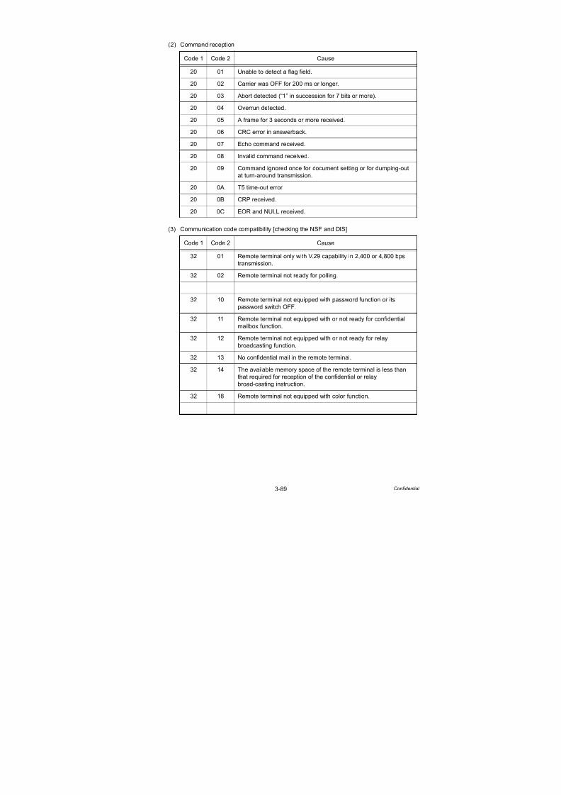
7/18/2019 Brother Mfc 9125cn 9325cw en 5694 Mfp Sm
http://slidepdf.com/reader/full/brother-mfc-9125cn-9325cw-en-5694-mfp-sm 181/597
3-89 Confidential
(2) Command reception
(3) Communication code compatibility [checking the NSF and DIS]
Code 1 Code 2 Cause
20 01 Unable to detect a flag field.
20 02 Carrier was OFF for 200 ms or longer.
20 03 Abort detected (“1” in succession for 7 bits or more).
20 04 Overrun detected.
20 05 A frame for 3 seconds or more received.
20 06 CRC error in answerback.
20 07 Echo command received.
20 08 Invalid command received.
20 09 Command ignored once for document setting or for dumping-out
at turn-around transmission.
20 0A T5 time-out error
20 0B CRP received.
20 0C EOR and NULL received.
Code 1 Code 2 Cause
32 01 Remote terminal only with V.29 capability in 2,400 or 4,800 bps
transmission.
32 02 Remote terminal not ready for polling.
32 10 Remote terminal not equipped with password function or its
password switch OFF.
32 11 Remote terminal not equipped with or not ready for confidential
mailbox function.
32 12 Remote terminal not equipped with or not ready for relay
broadcasting function.
32 13 No confidential mail in the remote terminal.
32 14 The available memory space of the remote terminal is less than
that required for reception of the confidential or relay
broad-casting instruction.
32 18 Remote terminal not equipped with color function.
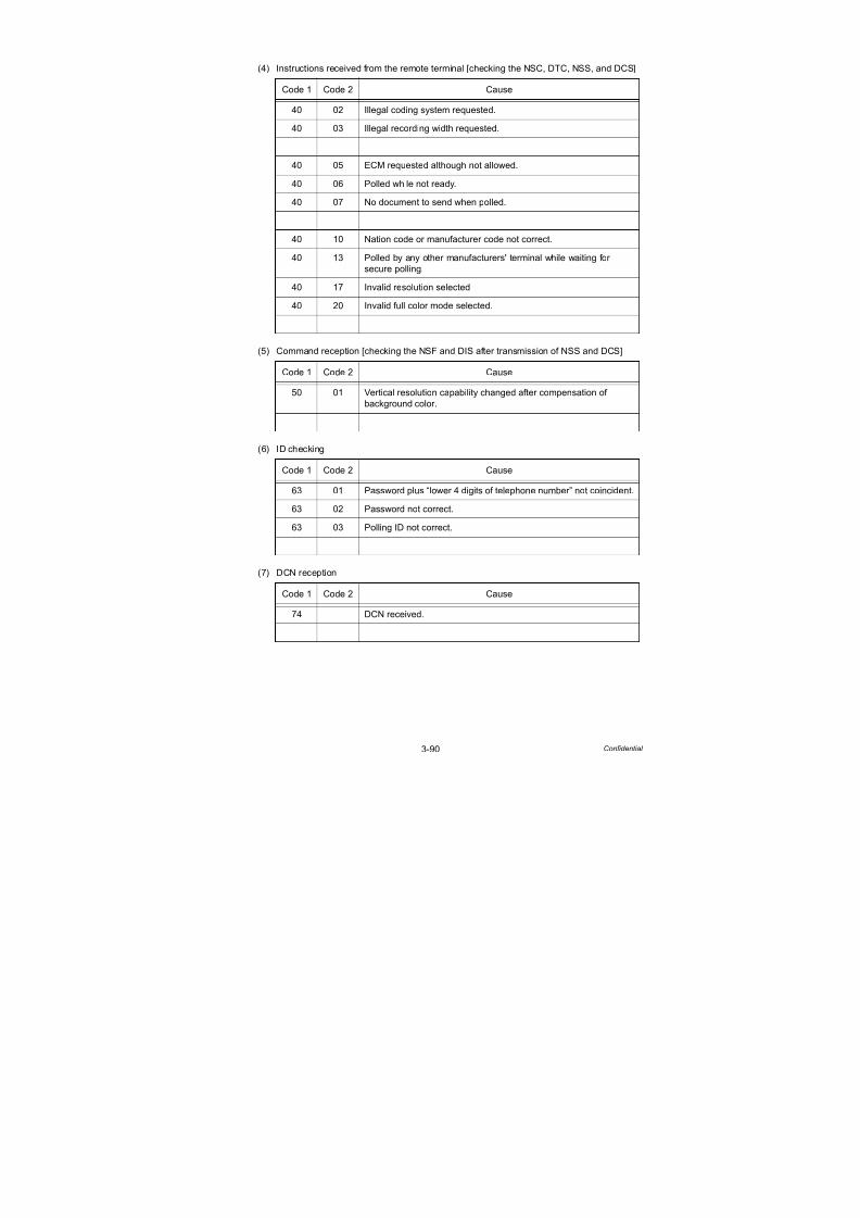
7/18/2019 Brother Mfc 9125cn 9325cw en 5694 Mfp Sm
http://slidepdf.com/reader/full/brother-mfc-9125cn-9325cw-en-5694-mfp-sm 182/597
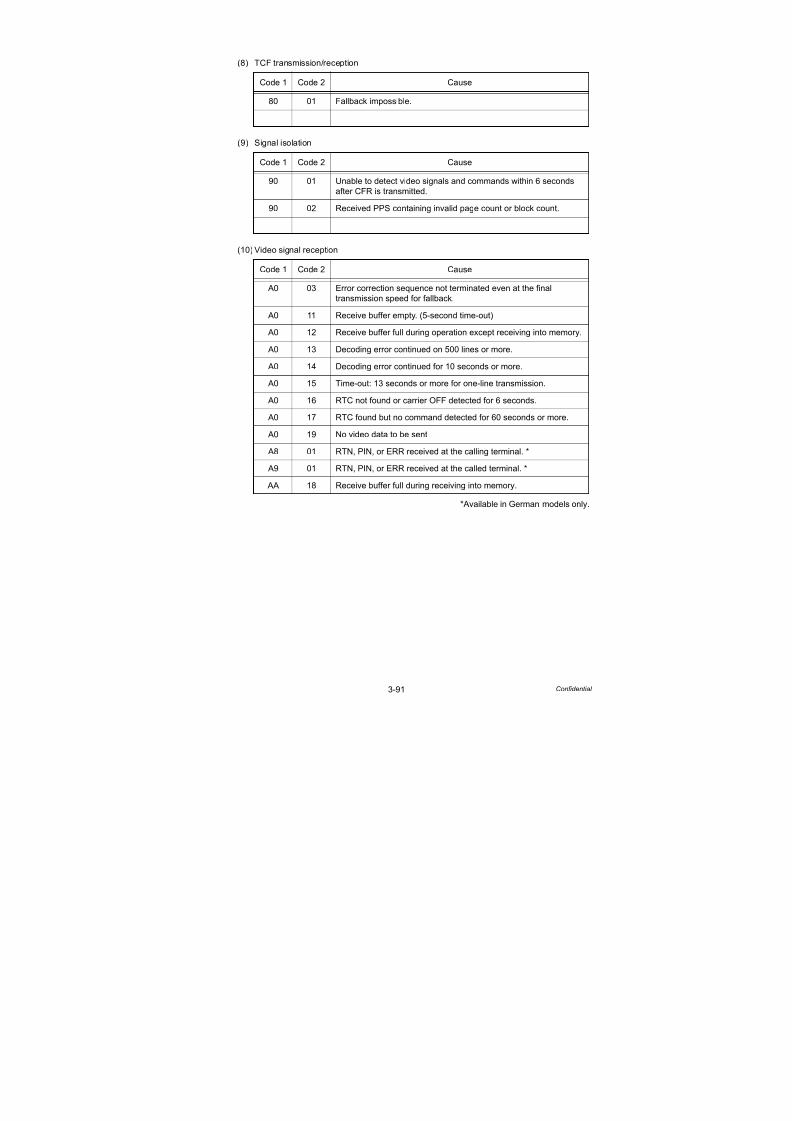
7/18/2019 Brother Mfc 9125cn 9325cw en 5694 Mfp Sm
http://slidepdf.com/reader/full/brother-mfc-9125cn-9325cw-en-5694-mfp-sm 183/597
3-91 Confidential
(8) TCF transmission/reception
(9) Signal isolation
(10) Video signal reception
*Available in German models only.
Code 1 Code 2 Cause
80 01 Fallback impossible.
Code 1 Code 2 Cause
90 01 Unable to detect video signals and commands within 6 seconds
after CFR is transmitted.
90 02 Received PPS containing invalid page count or block count.
Code 1 Code 2 Cause
A0 03 Error correction sequence not terminated even at the final
transmission speed for fallback.
A0 11 Receive buffer empty. (5-second time-out)
A0 12 Receive buffer full during operation except receiving into memory.
A0 13 Decoding error continued on 500 lines or more.
A0 14 Decoding error continued for 10 seconds or more.
A0 15 Time-out: 13 seconds or more for one-line transmission.
A0 16 RTC not found or carrier OFF detected for 6 seconds.
A0 17 RTC found but no command detected for 60 seconds or more.
A0 19 No video data to be sent
A8 01 RTN, PIN, or ERR received at the calling terminal. *
A9 01 RTN, PIN, or ERR received at the called terminal. *
AA 18 Receive buffer full during receiving into memory.
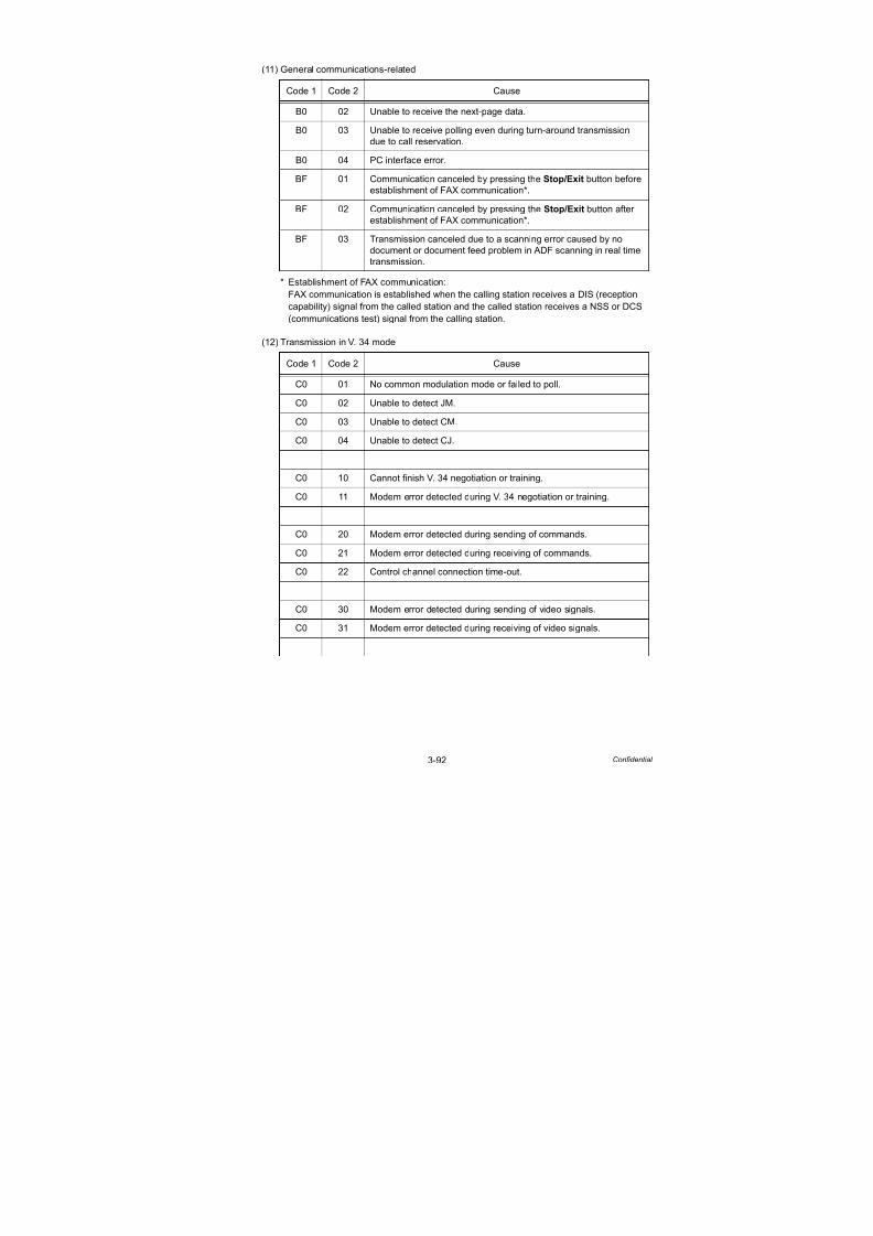
7/18/2019 Brother Mfc 9125cn 9325cw en 5694 Mfp Sm
http://slidepdf.com/reader/full/brother-mfc-9125cn-9325cw-en-5694-mfp-sm 184/597
3-92 Confidential
(11) General communications-related
* Establishment of FAX communication:
FAX communication is established when the calling station receives a DIS (reception
capability) signal from the called station and the called station receives a NSS or DCS
(communications test) signal from the calling station.
(12) Transmission in V. 34 mode
Code 1 Code 2 Cause
B0 02 Unable to receive the next-page data.
B0 03 Unable to receive polling even during turn-around transmission
due to call reservation.
B0 04 PC interface error.
BF 01 Communication canceled by pressing the Stop/Exit button before
establishment of FAX communication*.
BF 02 Communication canceled by pressing the Stop/Exit button after
establishment of FAX communication*.
BF 03 Transmission canceled due to a scanning error caused by no
document or document feed problem in ADF scanning in real time
transmission.
Code 1 Code 2 Cause
C0 01 No common modulation mode or failed to poll.
C0 02 Unable to detect JM.
C0 03 Unable to detect CM.
C0 04 Unable to detect CJ.
C0 10 Cannot finish V. 34 negotiation or training.
C0 11 Modem error detected during V. 34 negotiation or training.
C0 20 Modem error detected during sending of commands.
C0 21 Modem error detected during receiving of commands.
C0 22 Control channel connection time-out.
C0 30 Modem error detected during sending of video signals.
C0 31 Modem error detected during receiving of video signals.

7/18/2019 Brother Mfc 9125cn 9325cw en 5694 Mfp Sm
http://slidepdf.com/reader/full/brother-mfc-9125cn-9325cw-en-5694-mfp-sm 185/597
3-93 Confidential
(13) Maintenance mode
(14) Equipment error
Code 1 Code 2 Cause
E0 01 Failed to detect 1300 Hz signal in burn-in operation.
E0 02 Failed to detect PB signals in burn-in operation.
Code 1 Code 2 Cause
FF X X Equipment error
(For X X, refer to “2.1 Error Codes” in this chapter.)

7/18/2019 Brother Mfc 9125cn 9325cw en 5694 Mfp Sm
http://slidepdf.com/reader/full/brother-mfc-9125cn-9325cw-en-5694-mfp-sm 186/597
3-94 Confidential
8. TROUBLESHOOTING OF THE CONTROL
PANEL COVER ASSY
8.1 Nothing is Displayed on the LCD.
<User Check>
- Verify if the power switch is turned off.
Step Cause Check Result Remedy
1 Connection
between main PCB
and panel PCB
Are the main PCB and
panel PCB connected
properly?
No Reconnect the
connector properly.
2 Connection
between mainPCB and
low-voltage power
supply PCB ASSY
Are the main PCB and
low-voltage powersupply PCB ASSY
connected properly?
No Reconnect the
connector properly.
3 LCD Is the problem solved
after replacing the
LCD?
Yes Replace the LCD.
4 Panel PCB Is the problem solved
after replacing the panel
PCB ASSY?
Yes Replace the panel PCB
ASSY.
5 High-voltage power supply PCB ASSY Is the problem solvedafter replacing the
high-voltage power
supply PCB ASSY?
Yes Replace the high-voltage power supply
PCB ASSY.
6 Low-voltage Power
Supply PCB ASSY
Is the problem solved
after replacing the
low-voltage power
supply PCB ASSY?
Yes Replace the low-voltage
power supply PCB
ASSY.
7 Main PCB Is the problem solved
after replacing the main
PCB ASSY?
Yes Replace the main PCB
ASSY.

7/18/2019 Brother Mfc 9125cn 9325cw en 5694 Mfp Sm
http://slidepdf.com/reader/full/brother-mfc-9125cn-9325cw-en-5694-mfp-sm 187/597
3-95 Confidential
8.2 The control panel cover ASSY does not Work.
<User Check>
- Check whether the function lock is not set.
Step Cause CheckResult
Remedy
1 Key sticking Is there a key on the
panel stuck?
Yes Clean up the control
panel cover ASSY, or
remove the burrs from
control panel cover
ASSY and panel keys.
2 Connection
between main PCB
and panel PCB
Are the main PCB and
panel PCB connected
properly?
No Reconnect the
connector properly.
3 Rubber key Is the problem solved
after replacing the
rubber key?
Yes Replace the rubber Key.
4 Panel PCB Is the problem solved
after replacing the panel
PCB ASSY?
Yes Replace the panel PCB
ASSY.
5 Main PCB Is the problem solved
after replacing the main
PCB ASSY?
Yes Replace the main PCB
ASSY.
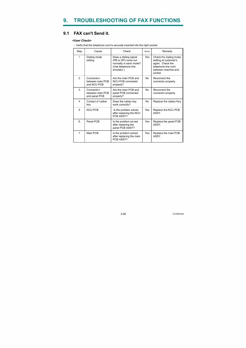
7/18/2019 Brother Mfc 9125cn 9325cw en 5694 Mfp Sm
http://slidepdf.com/reader/full/brother-mfc-9125cn-9325cw-en-5694-mfp-sm 188/597
3-96 Confidential
9. TROUBLESHOOTING OF FAX FUNCTIONS
9.1 FAX can't Send it.
<User Check>
- Verify that the telephone cord is securely inserted into the right socket.
Step Cause Check Result Remedy
1 Dialing mode
setting
Does a dialing signal
(PB or DP) come out
normally in each mode?
(Use telephone line
emulator.)
Yes Check the dialing mode
setting at customer's
again. Check the
telephone line cord
between machine and
socket.
2 Connectionbetween main PCB
and NCU PCB
Are the main PCB andNCU PCB connected
properly?
No Reconnect theconnector properly.
3 Connection
between main PCB
and panel PCB
Are the main PCB and
panel PCB connected
properly?
No Reconnect the
connector properly.
4 Contact of rubber
key
Does the rubber key
work correctly?
No Replace the rubber Key.
5 NCU PCB Is the problem solved
after replacing the NCU
PCB ASSY?
Yes Replace the NCU PCB
ASSY.
6 Panel PCB Is the problem solved
after replacing the
panel PCB ASSY?
Yes Replace the panel PCB
ASSY.
7 Main PCB Is the problem solved
after replacing the main
PCB ASSY?
Yes Replace the main PCB
ASSY.

7/18/2019 Brother Mfc 9125cn 9325cw en 5694 Mfp Sm
http://slidepdf.com/reader/full/brother-mfc-9125cn-9325cw-en-5694-mfp-sm 189/597
3-97 Confidential
9.2 Speed Dialing and One-touch Dialing can't be Used.
<User Check>
- Check that the Speed Dialing and One-touch Dialing are properly registered.
9.3 FAX can't be Received.
<User Check>
- Verify that the telephone cord is securely inserted into the right socket.
Step Cause Check Result Remedy
1 Speed dialing
keys or one-touch
dialing keys
Can a fax transmission
be made using the
numeric keys?
Yes Replace the main PCB
ASSY.
2 Dialing mode
setting
Does a dialing signal
(PB or DP) come out
normally in each mode?
(Use telephone line
emulator.)
Yes Check the dialing mode
setting at customer's
again.
Check the telephone
line cord between
machine and socket.
3 Connection
between main PCB
and NCU PCB
Are the main PCB and
NCU PCB connected
properly?
No Reconnect the
connector properly.
4 Connection
between main
PCB and panel
PCB
Are the main PCB and
panel PCB connected
properly?
No Reconnect the
connector properly.
5 Rubber key Is the problem solved
after replacing the
rubber key?
Yes Replace the rubber Key.
6 NCU PCB Is the problem solved
after replacing the NCUPCB ASSY?
Yes Replace the NCU PCB
ASSY.
7 Panel PCB Is the problem solved
after replacing the
panel PCB ASSY?
Yes Replace the panel PCB
ASSY.
Step Cause Check Result Remedy
1 Receive mode
setting
Is the receive mode set
to automatic receive
mode?
No Set the receive mode to
automatic receive
mode.
2 NCU PCB Is the problem solved
after replacing the NCU
PCB ASSY?
Yes Replace the NCU PCB
ASSY.
3 Main PCB Is the problem solved
after replacing the main
PCB ASSY?
Yes Replace the main PCB
ASSY.

7/18/2019 Brother Mfc 9125cn 9325cw en 5694 Mfp Sm
http://slidepdf.com/reader/full/brother-mfc-9125cn-9325cw-en-5694-mfp-sm 190/597
3-98 Confidential
9.4 No Bell Ring.
9.5 Speaker is Silent During On-hook Dialing.
Step Cause Check Result Remedy
1 Ring delay Ring delay is set to “0”. Yes Change the ring delay
settings to anothervalue.
2 Ring volume Ring volume is set to
“OFF”.
Yes Change the ring volume
setting to another value.
3 Connection
between main PCB
and NCU PCB
Are the main PCB and
NCU PCB connected
properly?
No Reconnect the
connector properly.
4 Speaker Is the problem solved
after replacing the
speaker unit?
Yes Replace the speaker
unit.
5 NCU PCB Is the problem solvedafter replacing the NCU
PCB ASSY?
Yes Replace the NCU PCB ASSY.
6 Main PCB Is the problem solved
after replacing the main
PCB ASSY?
Yes Replace the main PCB
ASSY.
Step Cause Check Result Remedy
1 Connection
between main PCB
and speaker
Are the main PCB and
speaker connected
properly?
No Reconnect the
connector properly.
2 Speaker Is the problem solved
after replacing the
speaker unit?
Yes Replace the speaker
unit.
3 Connection
between main PCB
and NCU PCB
Are the main PCB and
NCU PCB connected
properly?
No Reconnect the
connector properly.
4 Connection
between main
PCB and panel
PCB
Are the main PCB and
panel PCB connected
properly?
No Reconnect the
connector properly.
5 NCU PCB Is the problem solved
after replacing the NCU
PCB ASSY?
Yes Replace the NCU PCB
ASSY.
6 Main PCB Is the problem solved
after replacing the main
PCB ASSY?
Yes Replace the main PCB
ASSY.

7/18/2019 Brother Mfc 9125cn 9325cw en 5694 Mfp Sm
http://slidepdf.com/reader/full/brother-mfc-9125cn-9325cw-en-5694-mfp-sm 191/597
3-99 Confidential
9.6 Dialing Function does not Switch between “Tone” and
“Pulse.”
Step Cause Check Result Remedy
1 Connection
between main
PCB and NCU PCB
Are the main PCB and
NCU PCB connected
properly?
No Reconnect the
connector properly.
2 NCU PCB Is the problem solved
after replacing the NCU
PCB ASSY?
Yes Replace the NCU PCB
ASSY.
3 Main PCB Is the problem solved
after replacing the main
PCB ASSY?
Yes Replace the main PCB
ASSY.
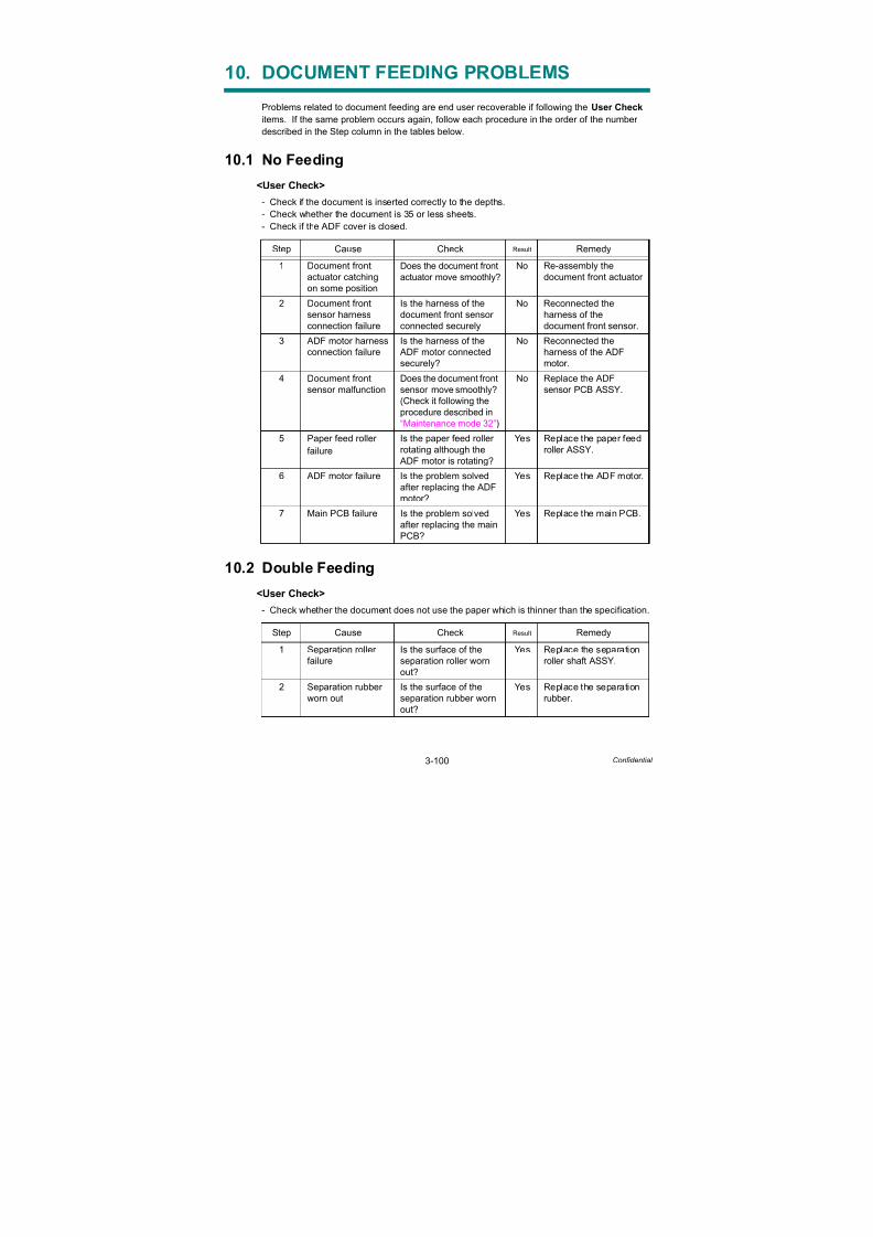
7/18/2019 Brother Mfc 9125cn 9325cw en 5694 Mfp Sm
http://slidepdf.com/reader/full/brother-mfc-9125cn-9325cw-en-5694-mfp-sm 192/597
3-100 Confidential
10. DOCUMENT FEEDING PROBLEMS
Problems related to document feeding are end user recoverable if following the User Check
items. If the same problem occurs again, follow each procedure in the order of the number
described in the Step column in the tables below.
10.1 No Feeding
<User Check>
- Check if the document is inserted correctly to the depths.
- Check whether the document is 35 or less sheets.
- Check if the ADF cover is closed.
10.2 Double Feeding
<User Check>
- Check whether the document does not use the paper which is thinner than the specification.
Step Cause Check Result Remedy
1 Document front
actuator catchingon some position
Does the document front
actuator move smoothly?
No Re-assembly the
document front actuator
2 Document front
sensor harness
connection failure
Is the harness of the
document front sensor
connected securely
No Reconnected the
harness of the
document front sensor.
3 ADF motor harness
connection failure
Is the harness of the
ADF motor connected
securely?
No Reconnected the
harness of the ADF
motor.
4 Document front
sensor malfunction
Does the document front
sensor move smoothly?
(Check it following the
procedure described in
“Maintenance mode 32”)
No Replace the ADF
sensor PCB ASSY.
5 Paper feed roller
failure
Is the paper feed roller
rotating although the
ADF motor is rotating?
Yes Replace the paper feed
roller ASSY.
6 ADF motor failure Is the problem solved
after replacing the ADF
motor?
Yes Replace the ADF motor.
7 Main PCB failure Is the problem solved
after replacing the main
PCB?
Yes Replace the main PCB.
Step Cause Check Result Remedy
1 Separation roller
failure
Is the surface of the
separation roller worn
out?
Yes Replace the separation
roller shaft ASSY.
2 Separation rubber
worn out
Is the surface of the
separation rubber wornout?
Yes Replace the separation
rubber.
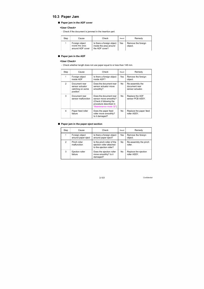
7/18/2019 Brother Mfc 9125cn 9325cw en 5694 Mfp Sm
http://slidepdf.com/reader/full/brother-mfc-9125cn-9325cw-en-5694-mfp-sm 193/597
3-101 Confidential
10.3 Paper Jam
Paper jam in the ADF cover
<User Check>
- Check if the document is jammed in the insertion part.
Paper jam in the ADF
<User Check>
- Check whether length does not use paper equal to or less than 148 mm.
Paper jam in the paper eject section
Step Cause Check Result Remedy
1 Foreign object
inside the area
around ADF cover
Is there a foreign object
inside the area around
the ADF cover?
Yes Remove the foreign
object.
Step Cause Check Result Remedy
1 Foreign object
inside ADF
Is there a foreign object
inside ADF?
Yes Remove the foreign
object.
2 Document rear
sensor actuator
catching on some
position
Does the document rear
sensor actuator move
smoothly?
No Re-assembly the
document rear
sensor actuator.
3 Document rear
sensor malfunction
Does the document rear
sensor move smoothly?
(Check it following the
procedure described in
“Maintenance mode 32”)
No Replace the ADF
sensor PCB ASSY.
4 Paper feed roller
failure
Does the paper feed
roller move smoothly?
Is it damaged?
No Replace the paper feed
roller ASSY.
Step Cause Check Result Remedy
1 Foreign object
around paper eject
Is there a foreign object
around paper eject?
Yes Remove the foreign
object.
2 Pinch roller
malfunction
Is the pinch roller of the
ejection roller attached
to the ejection roller?
No Re-assembly the pinch
roller.
3 Ejection roller
failure
Does the ejection roller
move smoothly? Is it
damaged?
No Replace the ejection
roller ASSY.

7/18/2019 Brother Mfc 9125cn 9325cw en 5694 Mfp Sm
http://slidepdf.com/reader/full/brother-mfc-9125cn-9325cw-en-5694-mfp-sm 194/597
3-102 Confidential
10.4 Wrinkles
<User Check>
- Check if the document is loaded into the ADF correctly.
- Check whether the document guide matches the document size.
- Check whether the document does not curl.
Step Cause Check Result Remedy
1 Separation roller
worn out
Is the separation roller
worn out?
Yes Replace the roller
holder ASSY.
2 Paper feed roller
worn out
Is the paper feed roller
worn out?
Yes Replace the paper feed
roller ASSY.

7/18/2019 Brother Mfc 9125cn 9325cw en 5694 Mfp Sm
http://slidepdf.com/reader/full/brother-mfc-9125cn-9325cw-en-5694-mfp-sm 195/597
3-103 Confidential
11. SCANNING IMAGE DEFECT
TROUBLESHOOTING
11.1 Image Defect Examples
Fig. 3-18
11.2 Troubleshooting Image Defect
Image defect related problems are end user recoverable if following the User Check items.
If the same problem occurs, follow each procedure in the order of the number described in the
Step column in the tables below.
Light on the page
<User Check>
- Check whether the setting of the contrast does not become light.
Step Cause Check Result Remedy
1 White level data
malfunction
Is the problem solved by
performing the
acquisition of white leveldata. (Function code 55)
Yes Perform the acquisition
of white level data.
(Function code 55)
2 CIS unit failure Is the problem solved
after replacing the
document scanner unit?
Yes Replace the document
scanner unit.
3 Main PCB failure Is the problem solved
after replacing the Main
PCB ASSY?
Yes Replace the main PCB
ASSY.
Light Faulty registration Dark
Completely blank Vertical streaks White vertical streaks

7/18/2019 Brother Mfc 9125cn 9325cw en 5694 Mfp Sm
http://slidepdf.com/reader/full/brother-mfc-9125cn-9325cw-en-5694-mfp-sm 196/597
3-104 Confidential
Faulty registration
(1) ADF
(2) Document table
Dark
Step Cause Check Result Remedy
1 Fine adjustment
of scan start
position
misalignment
Is the problem solved
by performing the fine
adjustment of scan start
position.
(Function code 54)
Yes Perform the fine
adjustment of scan start
position.
(Function code 54)
2 Document rear
sensor actuator
catching on some
position
Does the document rear
sensor actuator move
smoothly?
No Re-assembly the
document rear sensor
actuator.
Step Cause Check Result Remedy
1 Fine adjustment
of scan start
position
misalignment
Is the problem solved
by performing the fine
adjustment of scan start
position.
(Function code 54)
Yes Perform the fine
adjustment of scan start
position.
(Function code 54)
2 CIS unit failure Is the problem solved
after replacing the
document scanner unit?
Yes Replace the document
scanner unit.
<User Check>
- Check whether the setting of the contrast does not become dark.
Step Cause Check Result Remedy
1 White level data
malfunction
Is the problem solved by
performing the
acquisition of white level
data. (Function code 55)
Yes Perform the acquisition
of white level data.
(Function code 55)
2 CIS unit failure Is the problem solved
after replacing the
document scanner unit?
Yes Replace the document
scanner unit.
3 Main PCB failure Is the problem solved
after replacing the main
PCB ASSY?
Yes Replace the main PCB
ASSY.

7/18/2019 Brother Mfc 9125cn 9325cw en 5694 Mfp Sm
http://slidepdf.com/reader/full/brother-mfc-9125cn-9325cw-en-5694-mfp-sm 197/597
3-105 Confidential
Completely blank
Vertical streaks
White vertical streaks
Step Cause Check Result Remedy
1 White level data
malfunction
Is the problem solved by
performing the
acquisition of white level
data. (Function code 55)
Yes Perform the acquisition
of white level data.
(Function code 55)
2 CIS unit failure Is the problem solved
after replacing the
document scanner unit?
Yes Replace the document
scanner unit.
3 Main PCB failure Is the problem solved
after replacing the main
PCB ASSY?
Yes Replace the main PCB
ASSY.
<User Check>
- Check if the ADF glass or document glass is not
stained.
Step Cause Check Result Remedy
1 CIS unit failure Is the problem solved
after replacing the
document scanner unit?
Yes Replace the document
scanner unit.
<User Check>- Check if the ADF glass or document glass is not stained.
Step Cause Check Result Remedy
1 CIS unit failure Is the problem solved
after replacing the
document scanner unit?
Yes Replace the document
scanner unit.

7/18/2019 Brother Mfc 9125cn 9325cw en 5694 Mfp Sm
http://slidepdf.com/reader/full/brother-mfc-9125cn-9325cw-en-5694-mfp-sm 198/597
3-106 Confidential
12. OTHERS PROBLEMS
12.1 The Machine is not Turned on, or the LCD Indication
does not Appear.
Step Cause Check Result Remedy
1 Harness
connection failure
of panel PCB
ASSY
Is the harness of the
panel PCB ASSY
connected correctly?
No Reconnect the panel
PCB ASSY harness.
2 Harness
connection failure
of LCD
Is the harness of the
LCD connected
correctly?
No Reconnect the LCD
harness.
3 LCD failure Is the problem solved
after replacing the
LCD?
Yes Replace the LCD.
4 Low-voltage power
supply PCB failure
Is the problem solved
after replacing the Low-
voltage power supply
PCB ASSY?
Yes Replace the low-voltage
power supply PCB
ASSY.
5 Panel PCB failure Is the problem solved
after replacing the panel
PCB ASSY?
Yes Replace the panel PCB
ASSY.
6 High-voltage powersupply PCB failure
Is the problem solvedafter replacing the
high-voltage power
supply PCB ASSY?
Yes Replace the high-voltage power
supply PCB ASSY.
7 Main PCB failure Is the problem solved
after replacing the main
PCB ASSY?
Yes Replace the main PCB
ASSY.
Note:
When the error code 36 occurs, the power is forcibly turned OFF, and the machine cannot
be turned ON for 10 minutes.

7/18/2019 Brother Mfc 9125cn 9325cw en 5694 Mfp Sm
http://slidepdf.com/reader/full/brother-mfc-9125cn-9325cw-en-5694-mfp-sm 199/597
3-107 Confidential
12.2 The Fan does not Work.
12.3 Pickup Function of Paper Tray does not Work.
Step Cause Check Result Remedy
1 Harness
connection failureof the appropriate
fan
Is the harness of the
appropriate fanconnected correctly?
No Reconnect the harness
of the appropriate fancorrectly.
2 Failure of the
appropriate fan
Is the problem solved
after replacing the
appropriate fan?
Yes Replace the appropriate
fan.
3 Engine PCB failure Is the problem solved
after replacing the
engine PCB ASSY?
Yes Replace the engine
PCB ASSY.
4 HVPS control PCB
failure
Is the problem solved
after replacing the
HVPS control PCB
ASSY?
Yes Replace the HVPS
control PCB ASSY.
5 High-voltage power
supply PCB failure
Is the problem solved
after replacing the
high-voltage power
supply PCB ASSY?
Yes Replace the high-
voltage power supply
PCB ASSY.
6 Low-voltage power
supply PCB failure
Is the problem solved
after replacing the
low-voltage power
supply PCB ASSY?
Yes Replace the low-voltage
power supply PCB
ASSY.
7 Main PCB failure Is the problem solved
after replacing the main
PCB ASSY?
Yes Replace the main PCB
ASSY.
Step Cause Remedy
1 Link lever catching on some position Re-assemble the link lever.
2 Pickup roller holder ASSY not
operating smoothly or catching.
Make sure correct movement of the
pickup roller holder ASSY.
3 Roller holder ASSY failure Replace the roller holder ASSY.
4 Paper feed motor failure Replace the Paper feed motor ASSY.

7/18/2019 Brother Mfc 9125cn 9325cw en 5694 Mfp Sm
http://slidepdf.com/reader/full/brother-mfc-9125cn-9325cw-en-5694-mfp-sm 200/597
3-108 Confidential
12.4 The New Toner is not Detected.
12.5 Printing from Macintosh Applications Fails.
<User Check>
- Check that the printer driver which, is supplied with the product, is installed in Library/Printers, and that the print queue is created.
- Check the connecting end on the printer browser. It must be matched with the connecting
end which is actually connected.
12.6 USB Direct Printing does not Work.(USB direct interface model only)
Step Cause Remedy
1 New toner actuator not operating
smoothly or catching.
Make sure correct movement of the
new toner actuator of the appropriatecolor.
2 Main PCB failure Replace the main PCB ASSY.
3 Toner/new sensor PCB failure Replace the toner/new sensor PCB
ASSY of the appropriate color.
Step Cause Check Result Remedy
1 Failure inside the
machine
Does the machine print
test pattern?
(Check it following the
procedure described in
“1.4.5 Monochromeimage quality test
pattern (Function code
09)” in Chapter 7.)
No Identify the error type,
and then refer to the
specified section of this
chapter.
2 Breakage of main
PCB
Does the machine make
a print using a correct
computer and a USB
cable?
No Replace the main PCB
ASSY.
Step Cause Remedy
1 USB direct interface relay PCB failure Replace the USB direct interface relay
PCB ASSY.
2 Main PCB failure Replace the main PCB ASSY.

7/18/2019 Brother Mfc 9125cn 9325cw en 5694 Mfp Sm
http://slidepdf.com/reader/full/brother-mfc-9125cn-9325cw-en-5694-mfp-sm 201/597
Confidential
CHAPTER 4PERIODICAL MAINTENANCE

7/18/2019 Brother Mfc 9125cn 9325cw en 5694 Mfp Sm
http://slidepdf.com/reader/full/brother-mfc-9125cn-9325cw-en-5694-mfp-sm 202/597
Confidential
CHAPTER 4
PERIODICAL MAINTENANCEThis chapter details consumable parts and periodical maintenance parts. This chapter also covers
procedures for disassembling and assembling periodical maintenance parts.
CONTENTS
1. SAFETY PRECAUTIONS ..........................................................................4-1
2. CONSUMABLE PARTS .............................................................................4-1
3. PERIODICAL MAINTENANCE PARTS .....................................................4-3
3.1 Periodical Maintenance Parts..................................................................................... 4-3
3.2 Procedures to Replace Periodical Maintenance Parts ............................................... 4-4
3.2.1 Fuser unit........................................................................................................... 4-5
3.2.2 Paper feeding kit.............................................................................................. 4-17
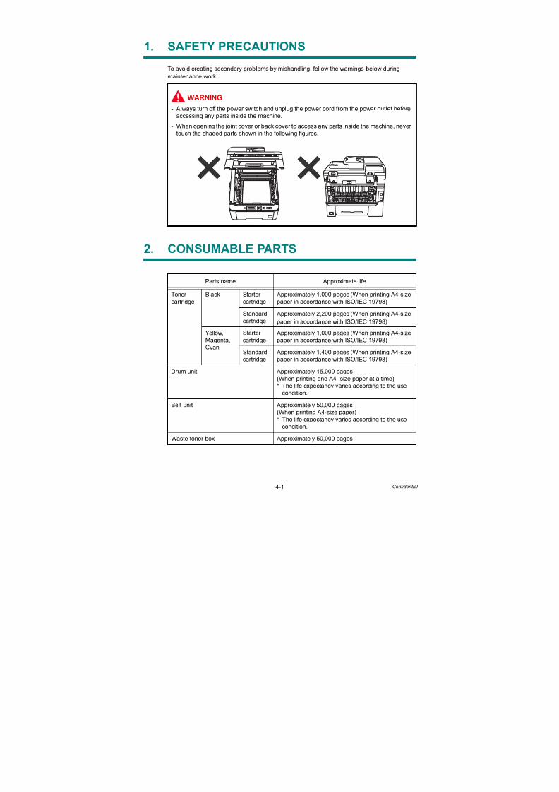
7/18/2019 Brother Mfc 9125cn 9325cw en 5694 Mfp Sm
http://slidepdf.com/reader/full/brother-mfc-9125cn-9325cw-en-5694-mfp-sm 203/597
4-1 Confidential
1. SAFETY PRECAUTIONS
To avoid creating secondary problems by mishandling, follow the warnings below during
maintenance work.
2. CONSUMABLE PARTS
WARNING
- Always turn off the power switch and unplug the power cord from the power outlet before
accessing any parts inside the machine.
- When opening the joint cover or back cover to access any parts inside the machine, never
touch the shaded parts shown in the following figures.
Parts name Approximate life
Toner
cartridge
Black Starter
cartridge
Approximately 1,000 pages (When printing A4-size
paper in accordance with ISO/IEC 19798)
Standard
cartridge
Approximately 2,200 pages (When printing A4-size
paper in accordance with ISO/IEC 19798)
Yellow,
Magenta,
Cyan
Starter
cartridge
Approximately 1,000 pages (When printing A4-size
paper in accordance with ISO/IEC 19798)
Standard
cartridge
Approximately 1,400 pages (When printing A4-size
paper in accordance with ISO/IEC 19798)
Drum unit Approximately 15,000 pages
(When printing one A4- size paper at a time)
* The life expectancy varies according to the use
condition.
Belt unit Approximately 50,000 pages
(When printing A4-size paper)
* The life expectancy varies according to the use
condition.
Waste toner box Approximately 50,000 pages

7/18/2019 Brother Mfc 9125cn 9325cw en 5694 Mfp Sm
http://slidepdf.com/reader/full/brother-mfc-9125cn-9325cw-en-5694-mfp-sm 204/597
4-2 Confidential
Life of drum unit
< How to calculate the drum unit life >
The drum unit life is based on the “drum counter” or the “number of drum rotations”.The drum counter is based on the total printed pages on each drum unit. This totalprinted pages should be reset every time you replace the drum unit with a new one.(Refer to “2.1.3 Resetting the life counter of the drum unit” in Chapter 7.) Basically thisamount is equal to the assured printable pages of the drum unit.If the developing bias voltage correction or color registration adjustment is performedfrequently, however, only the number of drum rotations increases, and the “page counterbased on the number of drum rotation” exceeds the “drum counter” based on the totalprinted page.Refer to the calculation of the drum unit life based on the number of drum rotation below;
< How to calculate the page counter >
The number of drum rotations for the first page printed is about 28.The number of drum rotations per one page for the second or later page printed(continuous printing) is 5.Page counter based on the number of drum rotations = Number of drum rotations for thefirst page printed + [Number of drum rotations per one page for the second or later pageprinted x (Number of pages in continuous printing - 1)] / 28(* The number of drum rotations per one page continuous printing.)
Example: Starts to print when the machine is in the Ready state.
If you leave the machine without printing for a long time, the number of drum rotations isincreasing because the developing bias voltage correction and the color registration areperformed. If you print one page per one job every time after leaving the machine withoutprinting for a long time, the drum unit life is shorter than usual.The number of drum rotations required for the developing bias voltage correction = 55rotations.Example: Performs the developing bias voltage correction and starts to print after leaving
the machine without printing for a long time.
The number of drum rotations required for the color registration = 27 rotationsExample: Performs the color registration adjustment and starts to print after leaving the
machine without printing for a long time.
If the developing bias voltage correction and the color registration are performedcontinuously, the drum unit life is shorter.
Continuous printing Page counter based on the number of drum rotations (Pages)
1 page/job 28 + [5 x (1 - 1)] / 28 = 1
2 pages/job 28 + [5 x (2 - 1)] / 28 = 1.18
18 pages/job 28 + [5 x (18 - 1)] / 28 = 4.04
Continuous printing Page counter based on the number of drum rotations (Pages)
1 page/job 55 + 28 + [5 x (1 - 1)] / 28 = 2.96
2 pages/job 55 + 28 + [5 x (2 - 1)] / 28 = 3.14
18 pages/job 55 + 28 + [5 x (18 - 1)] / 28 = 6.00
Continuous printing Page counter based on the number of drum rotations (Pages)
1 page/job 27 + 28 + [5 x (1 - 1)] / 28 = 1.96
2 pages/job 27 + 28 + [5 x (2 - 1)] / 28 = 2.14
18 pages/job 27 + 28 + [5 x (18 - 1)] / 28 = 5.00

7/18/2019 Brother Mfc 9125cn 9325cw en 5694 Mfp Sm
http://slidepdf.com/reader/full/brother-mfc-9125cn-9325cw-en-5694-mfp-sm 205/597
4-3 Confidential
3. PERIODICAL MAINTENANCE PARTS
3.1 Periodical Maintenance Parts
Periodical maintenance parts are the parts to be replaced periodically to maintain productquality. These parts would affect the product quality if they loose their functionality even if they
do not appear to be damaged or there is no change in their appearance.
The periodical maintenance parts listed in the table below should be replaced according to the
service life.
* The paper feeding kit includes the separation pad ASSY, pad spring and roller holder ASSY.
When replacing the periodical maintenance parts, each of the counters need to be reset in
order to record the number of replacement times.
(Refer to “2.1 Resetting the Periodical Maintenance Parts Life” in Chapter7.)
The number of print pages of the machine can be checked in the log information display
(maintenance mode 80). (Refer to “1.4.27 Display of the machine’s log” in Chapter 7.)
The actual number of printed page will vary depending on the type of print job or the paper to
being used. The figures indicated as the approximate life in the table above are worked out
when printing a general business document (in accordance with ISO/IEC 19798) on A4-size
paper.
Parts name LCD Approximate lifeReplacement
procedure
Fuser unit Replace Fuser 50,000 pages Refer to 3.2.1
Paper feeding kit* Replace PF Kit 50,000 pages Refer to 3.2.2
Note:
- Always turn off the power switch of the machine and unplug the power cord from the
power outlet before replacing the periodical maintenance parts.
- If the fuser unit is replaced after an error related to the fuser unit occurs, you need to wait
until the machine sufficiently cools down before replacing the unit. After replacing the
unit, turn ON the machine and leave it for approximately fifteen minutes. This will make
the machine to be released from the error.
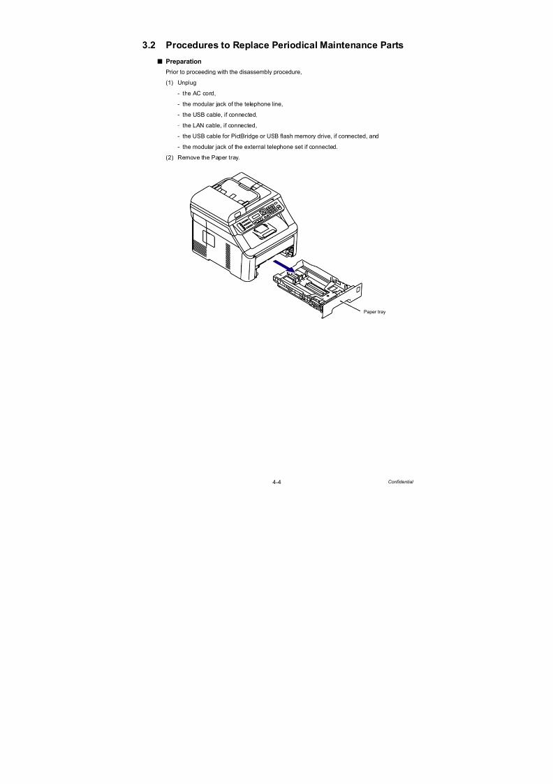
7/18/2019 Brother Mfc 9125cn 9325cw en 5694 Mfp Sm
http://slidepdf.com/reader/full/brother-mfc-9125cn-9325cw-en-5694-mfp-sm 206/597
4-4 Confidential
3.2 Procedures to Replace Periodical Maintenance Parts
Preparation
Prior to proceeding with the disassembly procedure,
(1) Unplug
- the AC cord,
- the modular jack of the telephone line,
- the USB cable, if connected,
- the LAN cable, if connected,
- the USB cable for PictBridge or USB flash memory drive, if connected, and
- the modular jack of the external telephone set if connected.
(2) Remove the Paper tray.
Paper tray

7/18/2019 Brother Mfc 9125cn 9325cw en 5694 Mfp Sm
http://slidepdf.com/reader/full/brother-mfc-9125cn-9325cw-en-5694-mfp-sm 207/597
4-5 Confidential
3.2.1 Fuser unit
<Uninstalling procedure>
(1) Open the Back cover.
Fig. 4-1
(2) Release the Hook and remove the Back cover stopper L and R from the Main body.
Fig. 4-2
Back cover
<Back side>
Hook
Back cover stopper L
Back cover stopper R
Main body
<Back side>
Back cover

7/18/2019 Brother Mfc 9125cn 9325cw en 5694 Mfp Sm
http://slidepdf.com/reader/full/brother-mfc-9125cn-9325cw-en-5694-mfp-sm 208/597
4-6 Confidential
(3) Remove the Bush of the Back cover from the Shaft at the right side of the Main body.
Fig. 4-3
(4) Remove the Back cover from the Shaft at the left of the Main body.
Fig. 4-4
Main body
Back cover
Bush
Bush
Shaft
Shaft
<Right side>
3a
3b
3c
<Back side>
Main body
Shaft
Back cover
<Left side>
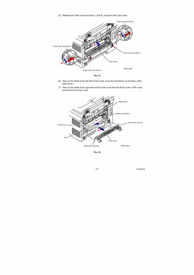
7/18/2019 Brother Mfc 9125cn 9325cw en 5694 Mfp Sm
http://slidepdf.com/reader/full/brother-mfc-9125cn-9325cw-en-5694-mfp-sm 209/597

7/18/2019 Brother Mfc 9125cn 9325cw en 5694 Mfp Sm
http://slidepdf.com/reader/full/brother-mfc-9125cn-9325cw-en-5694-mfp-sm 210/597
4-8 Confidential
(8) Remove the Taptite bind B M3x12 screw, and then remove the Fuser cover L from the
Fuser unit.
Fig. 4-7
(9) Remove the Taptite bind B M3x12 screw, and then remove the Fuser cover R from the
Fuser unit.
Fig. 4-8
Fuser unit
Fuser cover L
Taptite bind B M3x12
<Back side>
Taptite bind B M3x12
Fuser unit
Fuser cover R
<Back side>

7/18/2019 Brother Mfc 9125cn 9325cw en 5694 Mfp Sm
http://slidepdf.com/reader/full/brother-mfc-9125cn-9325cw-en-5694-mfp-sm 211/597
4-9 Confidential
(10) Disconnect the two Connectors (CN1, CN3) from the Eject front sensor PCB ASSY.
Fig. 4-9
(11) Disconnect the two Electrode terminals from the Fuser unit.
Fig. 4-10
Connector
CN1
Eject front sensor PCB ASSY
CN1CN3
Connector
CN3
<Back side>
Electrode terminal (small)
Electrode terminal (large)
Fuser unit
<Back side>

7/18/2019 Brother Mfc 9125cn 9325cw en 5694 Mfp Sm
http://slidepdf.com/reader/full/brother-mfc-9125cn-9325cw-en-5694-mfp-sm 212/597
4-10 Confidential
(12) Remove the two Taptite pan B M4x14 screws, and then remove the Fuser unit from the
Main body while holding the “A.”
Fig. 4-11
Fig. 4-12
Note:
- Do not apply a physical impact or vibration to the Fuser unit.
- Do not touch the roller and electrodes as shown in the figure below to prevent
breakage of the Fuser unit.
Taptite pan B M4x14
Taptite pan B M4x14
Fuser unit
Main body
“A”
<Back side>
Pressure roller ASSY
Fuser unit Fuser unit
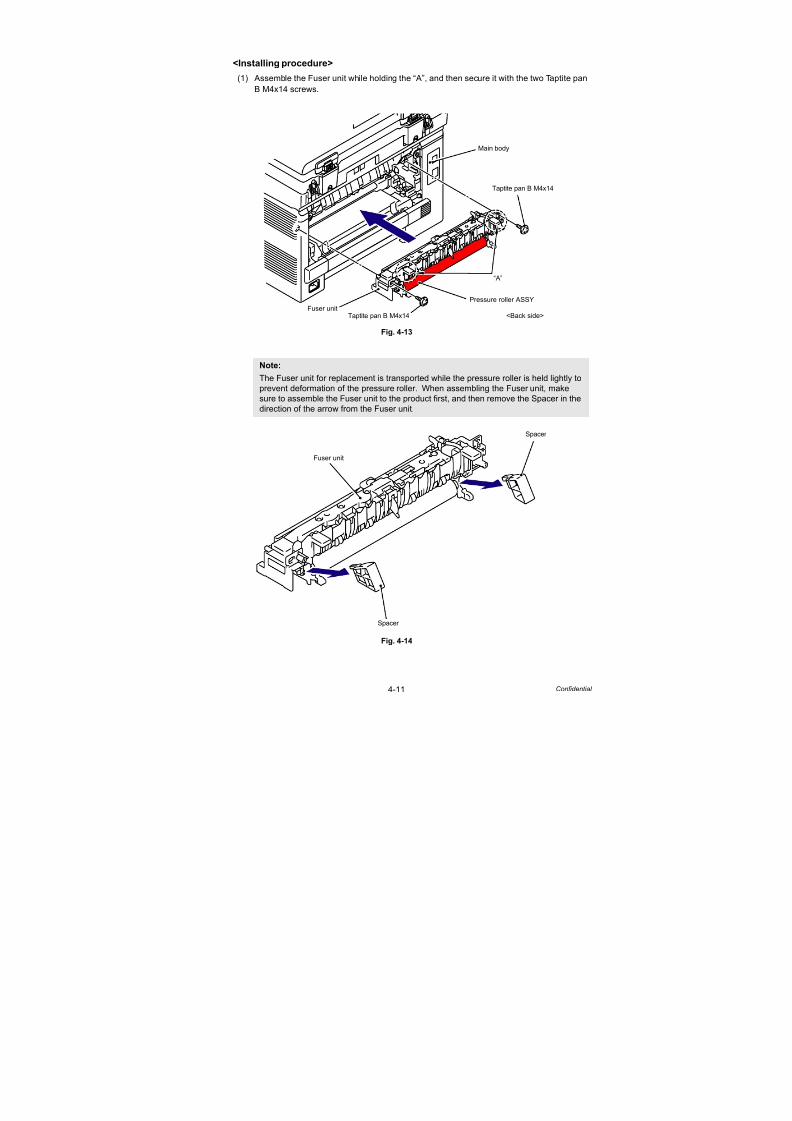
7/18/2019 Brother Mfc 9125cn 9325cw en 5694 Mfp Sm
http://slidepdf.com/reader/full/brother-mfc-9125cn-9325cw-en-5694-mfp-sm 213/597
4-11 Confidential
<Installing procedure>
(1) Assemble the Fuser unit while holding the “A”, and then secure it with the two Taptite pan
B M4x14 screws.
Fig. 4-13
Fig. 4-14
Note:
The Fuser unit for replacement is transported while the pressure roller is held lightly toprevent deformation of the pressure roller. When assembling the Fuser unit, make
sure to assemble the Fuser unit to the product first, and then remove the Spacer in the
direction of the arrow from the Fuser unit.
Taptite pan B M4x14
Taptite pan B M4x14
Fuser unit
Main body
“A”
Pressure roller ASSY
<Back side>
Fuser unit
Spacer
Spacer

7/18/2019 Brother Mfc 9125cn 9325cw en 5694 Mfp Sm
http://slidepdf.com/reader/full/brother-mfc-9125cn-9325cw-en-5694-mfp-sm 214/597
4-12 Confidential
(2) Connect the two Electrode terminals into the Fuser unit.
Fig. 4-15
(3) Connect the two connectors (CN1, CN3) into the Eject front sensor PCB ASSY.
Fig. 4-16
Electrode terminal (large)
Electrode terminal (small)
Fuser unit
<Back side>
Connector
CN1
Eject front sensor PCB ASSY
CN1CN3
Connector
CN3
<Back side>
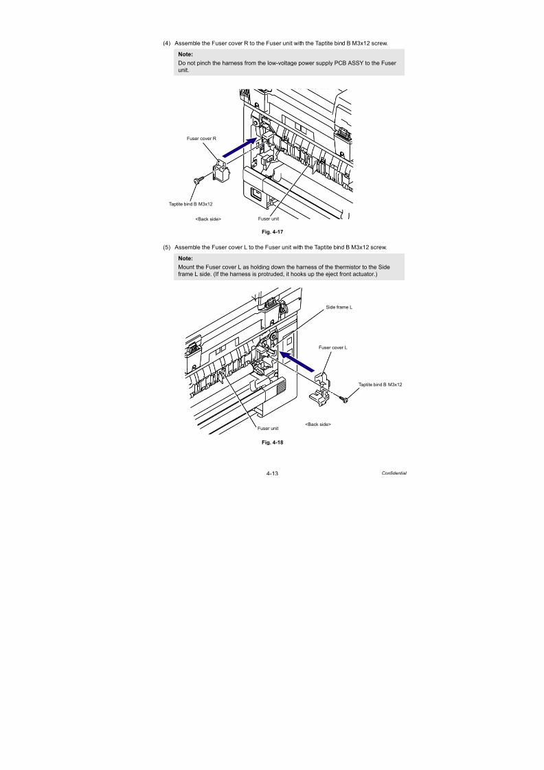
7/18/2019 Brother Mfc 9125cn 9325cw en 5694 Mfp Sm
http://slidepdf.com/reader/full/brother-mfc-9125cn-9325cw-en-5694-mfp-sm 215/597
4-13 Confidential
(4) Assemble the Fuser cover R to the Fuser unit with the Taptite bind B M3x12 screw.
Fig. 4-17
(5) Assemble the Fuser cover L to the Fuser unit with the Taptite bind B M3x12 screw.
Fig. 4-18
Note:
Do not pinch the harness from the low-voltage power supply PCB ASSY to the Fuser
unit.
Note:Mount the Fuser cover L as holding down the harness of the thermistor to the Side
frame L side. (If the harness is protruded, it hooks up the eject front actuator.)
Taptite bind B M3x12
Fuser unit
Fuser cover R
<Back side>
Fuser unit
Fuser cover L
Taptite bind B M3x12
<Back side>
Side frame L
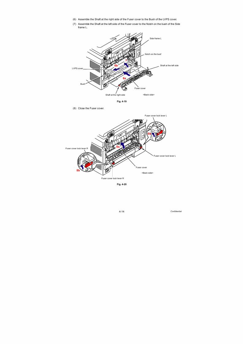
7/18/2019 Brother Mfc 9125cn 9325cw en 5694 Mfp Sm
http://slidepdf.com/reader/full/brother-mfc-9125cn-9325cw-en-5694-mfp-sm 216/597
4-14 Confidential
(6) Assemble the Shaft at the right side of the Fuser cover to the Bush of the LVPS cover.
(7) Assemble the Shaft at the left side of the Fuser cover to the Notch on the bush of the Side
frame L.
Fig. 4-19
(8) Close the Fuser cover.
Fig. 4-20
Bush
Shaft at the left side
LVPS cover
Notch on the bush
Fuser cover
Shaft at the right side
7
6a
6b
<Back side>
Side frame L
Fuser cover
Fuser cover lock lever R8a
<Back side>
Fuser cover lock lever L
Fuser cover lock lever R
Fuser cover lock lever L
8b
8b
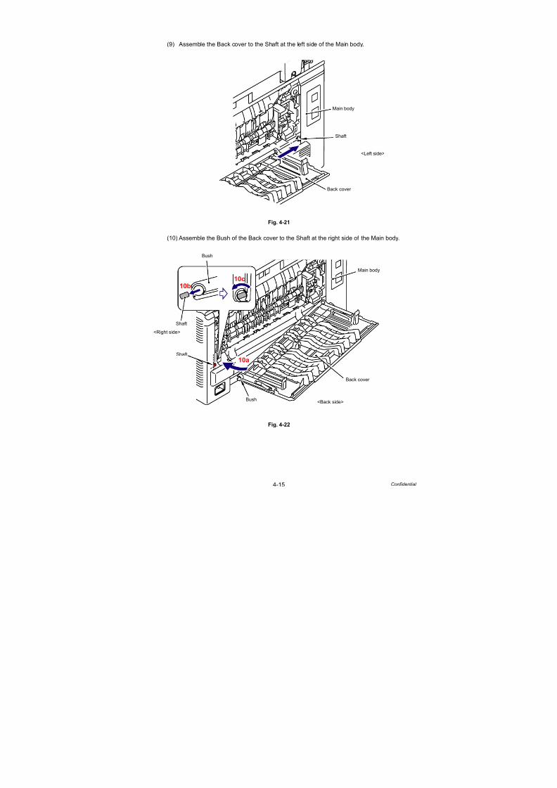
7/18/2019 Brother Mfc 9125cn 9325cw en 5694 Mfp Sm
http://slidepdf.com/reader/full/brother-mfc-9125cn-9325cw-en-5694-mfp-sm 217/597
4-15 Confidential
(9) Assemble the Back cover to the Shaft at the left side of the Main body.
Fig. 4-21
(10) Assemble the Bush of the Back cover to the Shaft at the right side of the Main body.
Fig. 4-22
Main body
Shaft
Back cover
<Left side>
Main body
Back cover
Bush
Bush
Shaft
Shaft
<Back side>
<Right side>
10b10c
10a

7/18/2019 Brother Mfc 9125cn 9325cw en 5694 Mfp Sm
http://slidepdf.com/reader/full/brother-mfc-9125cn-9325cw-en-5694-mfp-sm 218/597
4-16 Confidential
(11) Assemble the Back cover stopper L and Back cover stopper R to the Main body.
Fig. 4-23
(12) Close the Back cover.
Fig. 4-24
(13) After replacing the Fuser unit, reset the counter. (Refer to “2.1 Resetting the Periodical
Maintenance Parts Life” in Chapter7.)
Hook
Back cover stopper L
Back cover stopper R
Main body
<Back side>
Back cover
Back cover
<Back side>

7/18/2019 Brother Mfc 9125cn 9325cw en 5694 Mfp Sm
http://slidepdf.com/reader/full/brother-mfc-9125cn-9325cw-en-5694-mfp-sm 219/597
4-17 Confidential
3.2.2 Paper feeding kit
<Uninstalling procedure>
(1) Release the two Hooks of the Separation pad ASSY from the Paper tray.
(2) Release the two Pins to remove the Separation pad ASSY from Paper tray.
Fig. 4-25
(3) Remove the Pad spring from the Paper tray.
Fig. 4-26
Note:
Be careful not to lose the Pad spring.
Paper tray
Separation pad ASSY
Hook
Pin
Hook
Pin
2a
2b
Paper tray
Pad spring

7/18/2019 Brother Mfc 9125cn 9325cw en 5694 Mfp Sm
http://slidepdf.com/reader/full/brother-mfc-9125cn-9325cw-en-5694-mfp-sm 220/597
4-18 Confidential
(4) Push the Lift arm to the back and remove “B” of the Roller holder ASSY from “A” of the Lift
arm, and the Roller holder ASSY rotates in the direction of the arrow 4b.
Fig. 4-27
(5) Slide the Roller holder ASSY in the direction of the arrow 5 and remove it from the “C” of
the Paper feed unit.
(6) Slide the Roller holder ASSY in the direction of the arrow 6a and 6b in this order and
remove it.
Fig. 4-28
Lift arm
Lift arm
“A”
Roller holder
“B”Paper feed unit
“B”
Roller holder ASSY
Paper feed unit
“A”
<Front>
4a
4b
4a
4b
ASSY
Paper feed unit
“C”
Roller holder ASSY
5 6a
6b

7/18/2019 Brother Mfc 9125cn 9325cw en 5694 Mfp Sm
http://slidepdf.com/reader/full/brother-mfc-9125cn-9325cw-en-5694-mfp-sm 221/597
4-19 Confidential
<Installing procedure>
(1) Align the Shaft of the Roller holder ASSY to the Hole of the Paper feed unit and insert it
into the Hole.
Fig. 4-29
(2) Slide the Roller holder ASSY in the direction of the arrow 2a and 2b in this order, and fitthe “B” of the Roller holder ASSY into the “A” of the Paper feed unit.
Fig. 4-30
Roller holder ASSY
Paper feed unit
Paper feed unit
Hole
Shaft
1a
1b
1a
Paper feed unit
“A”
Roller holder ASSY
2a 2b
“B”

7/18/2019 Brother Mfc 9125cn 9325cw en 5694 Mfp Sm
http://slidepdf.com/reader/full/brother-mfc-9125cn-9325cw-en-5694-mfp-sm 222/597
4-20 Confidential
(3) Turn the Roller holder ASSY in the direction of the arrow 3a and insert the “D” of the
Roller holder ASSY into the “C” of the Lift arm.
Fig. 4-31
(4) Assemble the Pad spring onto the Paper tray.
Fig. 4-32
Lift arm
Lift arm
“C”
Roller holder
“D”Paper feed unit
“D”
Roller holder ASSY
Paper feed unit
“C”
3a
3b
<Front>
ASSY
3a
3b
Paper tray
Pad spring
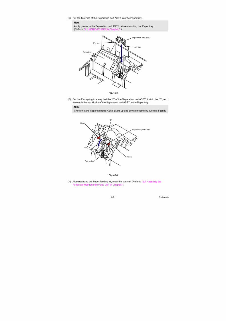
7/18/2019 Brother Mfc 9125cn 9325cw en 5694 Mfp Sm
http://slidepdf.com/reader/full/brother-mfc-9125cn-9325cw-en-5694-mfp-sm 223/597
4-21 Confidential
(5) Put the two Pins of the Separation pad ASSY into the Paper tray.
Fig. 4-33
(6) Set the Pad spring in a way that the “E” of the Separation pad ASSY fits into the “F”, and
assemble the two Hooks of the Separation pad ASSY to the Paper tray.
Fig. 4-34
(7) After replacing the Paper feeding kit, reset the counter. (Refer to “2.1 Resetting the
Periodical Maintenance Parts Life” in Chapter7.)
Note:
Apply grease to the Separation pad ASSY before mounting the Paper tray.
(Refer to “4. LUBRICATUION” in Chapter 5.)
Note:
Check that the Separation pad ASSY pivots up and down smoothly by pushing it gently.
Separation pad ASSY
Pin
Pin
Paper tray
Pad spring
Separation pad ASSY
Hook
Hook
“E”
“F”

7/18/2019 Brother Mfc 9125cn 9325cw en 5694 Mfp Sm
http://slidepdf.com/reader/full/brother-mfc-9125cn-9325cw-en-5694-mfp-sm 224/597
Confidential
CHAPTER 5DISASSEMBLY AND ASSEMBLY

7/18/2019 Brother Mfc 9125cn 9325cw en 5694 Mfp Sm
http://slidepdf.com/reader/full/brother-mfc-9125cn-9325cw-en-5694-mfp-sm 225/597
Confidential
CHAPTER 5
DISASSEMBLY AND ASSEMBLYThis chapter describes procedures for disassembling and assembling the machine with relates notes.
The provided disassembly order flow enables you to take in the quickest way to get an involved part ata glance.
At the start of disassembling, you can check the disassembly order flow which guides you through a
shortcut to get to the part.
This chapter also covers screw tightening torques and lubrication points where the specified lubrication
should be applied when the machine is assembled.
CONTENTS
1. SAFETY PRECAUTIONS ..........................................................................5-1
2. PACKING....................................................................................................5-2
3. SCREW TORQUE LIST .............................................................................5-3
4. LUBRICATION ...........................................................................................5-6
5. OVERVIEW OF GEARS.............................................................................5-8
6. HARNESS ROUTING...............................................................................5-12
7. DISASSEMBLY FLOW.............................................................................5-30
8. DISASSEMBLY PROCEDURE ................................................................5-32
8.1 Cord Hook ................................................................................................................ 5-33
8.2 EXT Cap ................................................................................................................... 5-34
8.3 Roller Holder ASSY .................................................................................................. 5-35
8.4 Separation Pad ASSY .............................................................................................. 5-37
8.5 Back Cover/Back Cover Stopper L/R ....................................................................... 5-39
8.6 Fuser Cover.............................................................................................................. 5-42
8.7 Paper Eject Front Actuator ....................................................................................... 5-438.8 Fuser Unit ................................................................................................................. 5-45
8.9 Side Cover L ASSY/Access Cover ........................................................................... 5-49
8.10 Side Cover R ASSY................................................................................................ 5-52
8.11 Pull Arm L/Pull Arm R/Pull Arm Spring ................................................................... 5-54
8.12 Hinge ASSY L......................................................................................................... 5-58
8.13 Hinge R/Hinge R Support/Hinge Base ................................................................... 5-60
8.14 ADF Cover ASSY ................................................................................................... 5-61
8.15 Gear Cover ............................................................................................................. 5-62
8.16 Separation Roller Shaft ASSY................................................................................ 5-63
7/18/2019 Brother Mfc 9125cn 9325cw en 5694 Mfp Sm
http://slidepdf.com/reader/full/brother-mfc-9125cn-9325cw-en-5694-mfp-sm 226/597
Confidential
8.17 Upper Document Chute ASSY ............................................................................... 5-64
8.18 Separation Rubber ASSY....................................................................................... 5-65
8.19 Paper Feed Roller ASSY........................................................................................ 5-66
8.20 Ejection Roller ASSY.............................................................................................. 5-67
8.21 ADF Sensor PCB ASSY ......................................................................................... 5-688.22 Drive Frame ASSY ................................................................................................. 5-71
8.23 Paper Stack Lever .................................................................................................. 5-75
8.24 Document Hold ASSY ............................................................................................ 5-76
8.25 Control Panel Cover ASSY..................................................................................... 5-77
8.26 Document Scanner Unit ......................................................................................... 5-78
8.27 Panel PCB ASSY ................................................................................................... 5-79
8.28 Rubber Key L/R ...................................................................................................... 5-80
8.29 LCD/LCD Cover...................................................................................................... 5-81
8.30 NCU PCB ASSY (NCU model only) ....................................................................... 5-83
8.31 Battery ASSY.......................................................................................................... 5-84
8.32 Pull Arm Guide ....................................................................................................... 5-85
8.33 Top Dress Cover L/R .............................................................................................. 5-86
8.34 FB Lock Lever L/R.................................................................................................. 5-87
8.35 Joint Cover Lock Spring/Joint Cover Lock Lever.................................................... 5-90
8.36 Wireless LAN PCB ASSY (Wireless LAN model only) ........................................... 5-91
8.37 USB Direct Interface Relay PCB ASSY (USB direct interface model only)............ 5-94
8.38 Panel Ground Plate 2 (Only the models without the USB direct interface) ............ 5-96
8.39 Speaker Unit/Front Cover Top Base....................................................................... 5-98
8.40 Front Cover............................................................................................................. 5-99
8.41 Manual Feed Slot ASSY....................................................................................... 5-101
8.42 TC Arm Spring ...................................................................................................... 5-102
8.43 Arm Guide L Cover............................................................................................... 5-106
8.44 Joint Cover Sub ASSY ......................................................................................... 5-107
8.45 Inner Chute ASSY 2 ............................................................................................. 5-110
8.46 TC Release Lever..................................................................................................5-111
8.47 Paper Stack Lever ASSY...................................................................................... 5-117
8.48 FFC Harness:MAIN-LED CTL .............................................................................. 5-118
8.49 LED Power Relay PCB ASSY .............................................................................. 5-121
8.50 LED Head Control PCB ASSY ............................................................................. 5-122
8.51 LED ASSY/Holder Hook ....................................................................................... 5-124
8.52 Z Spring L/Z Spring R ........................................................................................... 5-133
8.53 Develop Release Motor ASSY ............................................................................. 5-135
8.54 Main PCB ASSY................................................................................................... 5-1378.55 Engine PCB ASSY ............................................................................................... 5-138

7/18/2019 Brother Mfc 9125cn 9325cw en 5694 Mfp Sm
http://slidepdf.com/reader/full/brother-mfc-9125cn-9325cw-en-5694-mfp-sm 227/597
Confidential
8.56 Main PCB Insulation Sheet/Engine Insulation Sheet............................................ 5-139
8.57 Main PCB Shield Plate ......................................................................................... 5-140
8.58 Engine Shield Plate .............................................................................................. 5-141
8.59 Registration Mark Relay PCB ASSY .................................................................... 5-142
8.60 Drum Develop Drive Unit...................................................................................... 5-1438.61 Develop Drive Motor............................................................................................. 5-148
8.62 Paper Feed Motor ASSY...................................................................................... 5-149
8.63 Paper Feed Unit ................................................................................................... 5-151
8.64 Registration Front/Rear Sensor PCB ASSY......................................................... 5-154
8.65 Manual Sensor PCB ASSY .................................................................................. 5-156
8.66 Pick-up Sector Gear Spring/Friction Spring .......................................................... 5-157
8.67 PF Registration Solenoid...................................................................................... 5-160
8.68 Pick-up Solenoid/Pick-up Solenoid Lever Spring ................................................. 5-162
8.69 Fuser/Eject Drive Motor........................................................................................ 5-164
8.70 Fuser/Eject Drive Motor Sensor PCB ASSY ........................................................ 5-165
8.71 Top Cover Arm R .................................................................................................. 5-166
8.72 Top Cover Arm L................................................................................................... 5-167
8.73 Air Filter Holder ASSY/Ozone Filter ..................................................................... 5-168
8.74 Paper Eject Rear Actuator/Paper Eject Rear Actuator Spring/ Paper Eject Rear Actuator Top ............................................................................. 5-171
8.75 Eject Rear Sensor PCB ASSY ............................................................................. 5-174
8.76 Eject Front Sensor PCB ASSY............................................................................. 5-175
8.77 Toner/New Sensor PCB ASSY ............................................................................. 5-176
8.78 Belt Drive ASSY ................................................................................................... 5-177
8.79 Drum Motor Origin Sensor PCB ASSY................................................................. 5-178
8.80 LV Fan ASSY........................................................................................................ 5-179
8.81 Main Fan ASSY .................................................................................................... 5-181
8.82 Low-voltage Power Supply PCB ASSY ................................................................ 5-182
8.83 Registration Sensor Holder ASSY........................................................................ 5-188
8.84 High-voltage Power Supply PCB ASSY ............................................................... 5-1898.85 HVPS Control PCB ASSY .................................................................................... 5-195
8.86 Waste Toner Sensor ............................................................................................. 5-196
8.87 Develop Release Sensor PCB ASSY................................................................... 5-199
8.88 Belt Cleaner Spring............................................................................................... 5-200
8.89 TR Head Spring .................................................................................................... 5-204
8.90 Side Frame R ....................................................................................................... 5-206
8.91 Toner LED PCB ASSY/LED Holder ...................................................................... 5-209
8.92 LM Hook B/LM Hook C/Hook Spring BC10 .......................................................... 5-210
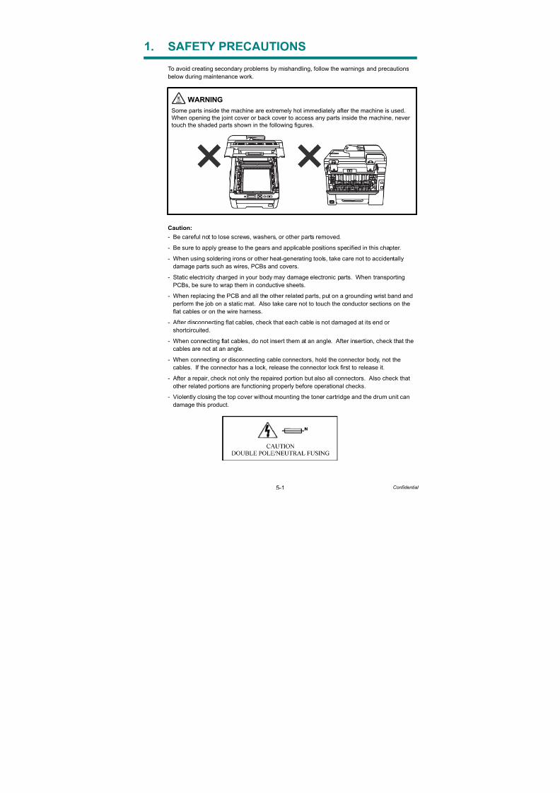
7/18/2019 Brother Mfc 9125cn 9325cw en 5694 Mfp Sm
http://slidepdf.com/reader/full/brother-mfc-9125cn-9325cw-en-5694-mfp-sm 228/597
5-1 Confidential
1. SAFETY PRECAUTIONS
To avoid creating secondary problems by mishandling, follow the warnings and precautions
below during maintenance work.
Caution:
- Be careful not to lose screws, washers, or other parts removed.
- Be sure to apply grease to the gears and applicable positions specified in this chapter.
- When using soldering irons or other heat-generating tools, take care not to accidentally
damage parts such as wires, PCBs and covers.- Static electricity charged in your body may damage electronic parts. When transporting
PCBs, be sure to wrap them in conductive sheets.
- When replacing the PCB and all the other related parts, put on a grounding wrist band and
perform the job on a static mat. Also take care not to touch the conductor sections on the
flat cables or on the wire harness.
- After disconnecting flat cables, check that each cable is not damaged at its end or
shortcircuited.
- When connecting flat cables, do not insert them at an angle. After insertion, check that the
cables are not at an angle.
- When connecting or disconnecting cable connectors, hold the connector body, not the
cables. If the connector has a lock, release the connector lock first to release it.
- After a repair, check not only the repaired portion but also all connectors. Also check that
other related portions are functioning properly before operational checks.
- Violently closing the top cover without mounting the toner cartridge and the drum unit can
damage this product.
WARNING
Some parts inside the machine are extremely hot immediately after the machine is used.
When opening the joint cover or back cover to access any parts inside the machine, never
touch the shaded parts shown in the following figures.

7/18/2019 Brother Mfc 9125cn 9325cw en 5694 Mfp Sm
http://slidepdf.com/reader/full/brother-mfc-9125cn-9325cw-en-5694-mfp-sm 229/597
5-2 Confidential
2. PACKING
Quick Setup guide
Printed bag ASSY
Carton option
Drum/Toner ASSY (M), (C)
AC cord bag ASSY
Polystyrene pad R
Machine
Polystyrene pad base
Carton
Carton option 3
Carton option 2
Carton option 3
Drum/Toner ASSY (Y)
Drum/Toner ASSY (K)
Polystyrene pad L

7/18/2019 Brother Mfc 9125cn 9325cw en 5694 Mfp Sm
http://slidepdf.com/reader/full/brother-mfc-9125cn-9325cw-en-5694-mfp-sm 230/597
5-3 Confidential
3. SCREW TORQUE LIST
Note:
For verifying the shape of each screw, refer to “APPENDIX 4 SCREW CATALOGUE”.
Location of screw Screw type Q'tyTightening torque
N·m (kgf ·cm)
Cord hook Taptite cup B M3x8 2 0.50±0.10 (5±1)
Fuser cover L Taptite bind B M3x12 1 0.60±0.10 (6±1)
Fuser cover R Taptite bind B M3x12 1 0.60±0.10 (6±1)
Fuser unit Taptite pan B M4x14 2 0.80±0.10 (8±1)
Side cover L ASSY Taptite bind B M4x12 2 0.80±0.10 (8±1)
Side cover R ASSY Taptite bind B M4x12 2 0.80±0.10 (8±1)
CIS harness hold plate Taptite cup S M3x6 SR 1 0.50±0.10 (5±1)Main shield cover plate ASSY Taptite cup S M3x6 SR 3 0.50±0.10 (5±1)
USB direct interface
FG harness ASSY
FB FG harness ASSY Taptite cup S M3x6 SR 1 0.50±0.10 (5±1)
ADF FG harness ASSY Taptite cup S M3x6 SR 1 0.50±0.10 (5±1)
NCU FG harness ASSY 2 Taptite cup S M3x6 SR 1 0.50±0.10 (5±1)
ADF unit Taptite bind B M4x12 2 0.80±0.10 (8±1)
Hinge ASSY L Taptite cup B M3x10 2 0.50±0.10 (5±1)
Taptite cup S M3x12 1 0.80±0.10 (8±1)
Hinge R support Taptite cup B M3x10 1 0.50±0.10 (5±1)
Hinge base Taptite cup B M3x10 3 0.50±0.10 (5±1)
Upper document chute ASSY Taptite cup B M3x10 4 0.50±0.10 (5±1)
Lower document chute ASSY Taptite cup B M3x10 2 0.50±0.10 (5±1)
ADF FG harness ASSY Taptite cup S M3x6 SR 1 0.80±0.10 (8±1)
Drive frame ASSY Taptite cup B M3x10 2 0.50±0.10 (5±1)
ADF motor Taptite bind S M3x6 1 0.80±0.10 (8±1)
Panel unit Taptite cup B M3x10 4 0.50±0.10 (5±1)
NCU shield Taptite pan (washer) B M4x12 DA 2 0.80±0.10 (8±1)
NCU FG harness ASSY 2
NCU FG harness ASSY 1 Screw PAN (S/P washer)
M3.5x6
1 0.50±0.10 (5±1)
NCU PCB ASSY Taptite cup S M3x6 SR 2 0.50±0.10 (5±1)
Top dress cover L Taptite bind B M4x12 1 0.90±0.10 (9±1)
Taptite cup B M3x8 2 0.50±0.10 (5±1)
Top dress cover R Taptite bind B M4x12 1 0.90±0.10 (9±1)
Taptite cup B M3x8 2 0.50±0.10 (5±1)
Blind cover L Taptite bind B M4x12 1 0.90±0.10 (9±1)
Blind cover R Taptite bind B M4x12 1 0.90±0.10 (9±1)
Front cover top ASSY Taptite bind B M4x12 2 0.70±0.10 (7±1)

7/18/2019 Brother Mfc 9125cn 9325cw en 5694 Mfp Sm
http://slidepdf.com/reader/full/brother-mfc-9125cn-9325cw-en-5694-mfp-sm 231/597

7/18/2019 Brother Mfc 9125cn 9325cw en 5694 Mfp Sm
http://slidepdf.com/reader/full/brother-mfc-9125cn-9325cw-en-5694-mfp-sm 232/597
5-5 Confidential
PF registration solenoid Taptite bind B M3x10 1 0.55±0.10 (5.5±1)
Pick-up solenoid Taptite bind B M3x10 1 0.55±0.10 (5.5±1)
Pick-up solenoid lever Fuser/Eject drive motor Taptite bind B M4x12 1 0.90±0.10 (9±1)
Taptite cup S M3x6 SR 1 0.80±0.10 (8±1)
Eject gear cover Taptite bind B M4x12 3 0.90±0.10 (9±1)
Paper eject guide ASSY Taptite bind B M4x12 4 0.90±0.10 (9±1)
Belt drive ASSY Taptite pan (washer)
B M4x12DA
3 0.70±0.10 (7±1)
Drum motor origin sensor PCB
ASSY
Taptite bind B M3x10 1 0.55±0.10 (5.5±1)
NCU harness holder Taptite bind B M4x12 2 0.90±0.10 (9±1)
Safety louver Taptite bind B M4x12 1 0.80±0.10 (8±1)FG harness Screw pan (S/P washer) M4x8
DB
1 0.80±0.10 (8±1)
Inlet
NCU FG harness ASSY 1 Screw pan (S/P washer) M4x8
DB
1 0.80±0.10 (8±1)
LVPS unit Taptite bind B M4x12 2 0.90±0.10 (9±1)
Taptite cup S M3x6 SR 2 0.50±0.10 (5±1)
LVPS plate Taptite pan (washer)
B M4x12DA
4 0.90±0.10 (9±1)
Low-voltage power supply
PCB ASSY
Taptite pan (washer)
B M4x12DA
1 0.90±0.10 (9±1)
Registration sensor holder ASSY Taptite cup S M3x6 SR 1 0.50±0.10 (5±1)
High-voltage power supply
PCB ASSY
Taptite bind B M4x12 2 0.70±0.10 (7±1)
Taptite pan (washer)
B M4x12DA
2 0.65±0.10 (6.5±1)
HVPS ground plate 2 Taptite cup S M3x6 SR 1 0.80±0.10 (8±1)
HVPS control PCB ASSY Taptite pan (S/P W) B M3x10 1 0.40±0.05 (4±0.5)
Develop release sensor PCB
ASSY
Taptite cup B M3x8 1 0.40±0.05 (4±0.5)
Side frame R Shoulder screw M3 4 0.80±0.10 (8±1)
Side frame L Shoulder screw M3 3 0.80±0.10 (8±1)Taptite cup S M3x6 SR 1 0.80±0.10 (8±1)
Bevel gear cover Taptite bind B M4x12 3 0.90±0.10 (9±1)
Location of screw Screw type Q'tyTightening torque
N·m (kgf ·cm)

7/18/2019 Brother Mfc 9125cn 9325cw en 5694 Mfp Sm
http://slidepdf.com/reader/full/brother-mfc-9125cn-9325cw-en-5694-mfp-sm 233/597
5-6 Confidential
4. LUBRICATION
PG2: MOLYKOTE PG-661 (W) (2 mm dia. ball)
BG2: FLOIL BG-MU (2 mm dia. ball)
EM2: MOLYKOTE EM-D110 (2 mm dia. ball)
The kind of the lubricating oil
(Maker name)Lubrication point Quantity of lubrication
MOLYKOTE PG-661 (W)
(Dow Corning)
Belt drive gear 2 mm dia. ball
LED ASSY 1 mm dia. ball
FLOIL BG-MU (Kanto Kasei) Belt drive gear 2 mm dia. ball
MOLYKOTE EM-D110
(Dow Corning)
Separation pad ASSY 2 mm dia. ball
Paper tray 2 mm dia. ball
PG2
PG1
BG2
EM2
EM2
BG2
BG2
PG2
Belt drive motor
Belt drive plate
Belt drive gear
2 places
16 places
8 places
* Around the center
* Around one third from
of tooth width
the tip of the tooth width
EM2
4 places Separation pad ASSY
Paper tray

7/18/2019 Brother Mfc 9125cn 9325cw en 5694 Mfp Sm
http://slidepdf.com/reader/full/brother-mfc-9125cn-9325cw-en-5694-mfp-sm 234/597
5-7 Confidential
EM2: MOLYKOTE EM-D110 (2 mm dia. ball)
PG1: MOLYKOTE PG-661 (W) (1 mm dia. ball)
EM2
Paper tray
2 places (one for each to the right and left)
PG1
1 place
LED ASSY

7/18/2019 Brother Mfc 9125cn 9325cw en 5694 Mfp Sm
http://slidepdf.com/reader/full/brother-mfc-9125cn-9325cw-en-5694-mfp-sm 235/597
5-8 Confidential
5. OVERVIEW OF GEARS
When ordering spare parts, please refer to Parts reference list.
Develop drive
<Development view>
<Layout view>
<Name of gears>
* These parts are subject to change without notice.
1 LU5128 Idle gear 100 5 LU5126 Idle gear 30
2 LU5127 Gear 63/85 6 LU5126 Idle gear 30
3 LU5124 Pendulum gear 50 7 LU5143 Gear 42/39
4 LU5125 Idle gear 35 8 LU5143 Gear 42/39
1
2
8
7
3
4
6
5
Side frame LDrum develop drive unit
<Left side>
3
4
5
6
8
1
2
3
4
5
687
Develop drive
Drum develop drive unit
plate ASSY

7/18/2019 Brother Mfc 9125cn 9325cw en 5694 Mfp Sm
http://slidepdf.com/reader/full/brother-mfc-9125cn-9325cw-en-5694-mfp-sm 236/597
5-9 Confidential
Drum develop drive
<Development view>
<Layout view>
<Name of gears>
* These parts are subject to change without notice.
9 LU5139 Drum drive gear ASSY 16 LU5136 Coupling idle gear 35
10 LU5132 Develop coupling gear 17 LU6157 Drum drive gear 60
11 LU5136 Coupling idle gear 35 18 LU5132 Develop coupling gear
12 LU6158 Drum idle gear 30 19 LU6158 Drum idle gear 30
13 LU6157 Drum drive gear 60 20 LU6157 Drum drive gear 60
14 LU5132 Develop coupling gear 21 LU5132 Develop coupling gear
15 LU6159 Drum drive gear 62/30
20
16
11
10
9
12
14
1821
13
17
1519
Drum develop drive unit
9
10
11
122
133
144
155
166
177
188
199
20
21
9
10
11
12
13
14
15
16
17
18
19
20
21
Drum develop drive unit
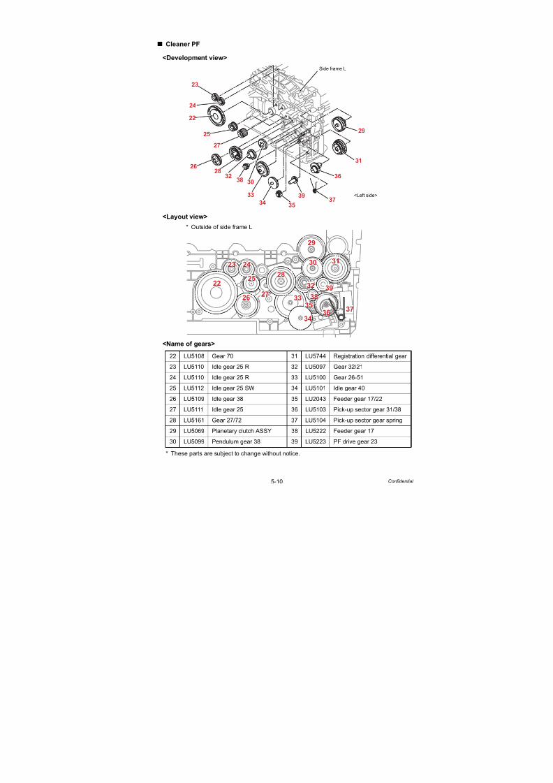
7/18/2019 Brother Mfc 9125cn 9325cw en 5694 Mfp Sm
http://slidepdf.com/reader/full/brother-mfc-9125cn-9325cw-en-5694-mfp-sm 237/597
5-10 Confidential
Cleaner PF
<Development view>
<Layout view>
* Outside of side frame L
<Name of gears>
* These parts are subject to change without notice.
22 LU5108 Gear 70 31 LU5744 Registration differential gear
23 LU5110 Idle gear 25 R 32 LU5097 Gear 32/21
24 LU5110 Idle gear 25 R 33 LU5100 Gear 26-51
25 LU5112 Idle gear 25 SW 34 LU5101 Idle gear 40
26 LU5109 Idle gear 38 35 LU2043 Feeder gear 17/22
27 LU5111 Idle gear 25 36 LU5103 Pick-up sector gear 31/38
28 LU5161 Gear 27/72 37 LU5104 Pick-up sector gear spring
29 LU5069 Planetary clutch ASSY 38 LU5222 Feeder gear 17
30 LU5099 Pendulum gear 38 39 LU5223 PF drive gear 23
22
23
24
25
27
2628
323038
33
3435
3937
36
31
29
Side frame L
<Left side>
222
233 244
255
266277
288
333
322
388
399
344
30
299
31
366377
355
22
23 24
25
26 27
28
33
32
38
39
34
30
29
31
36 37
35

7/18/2019 Brother Mfc 9125cn 9325cw en 5694 Mfp Sm
http://slidepdf.com/reader/full/brother-mfc-9125cn-9325cw-en-5694-mfp-sm 238/597
5-11 Confidential
PF drive
<Development view>
<Layout view>
* Inside of side frame L
<Name of gears>
* These parts are subject to change without notice.
40 LR0910 Hook spring 46 LU5089 Planetary clutch ASSY
41 LU5093 LM hook B 47 LR0910 Hook spring
42 LU5094 LM hook C 48 LU5105 Worm Z33
43 LU5095 P/P gear 26 sector 49 LU5106 Bevel gear Z17G
44 LU6447 P/P gear 26 sector spring 50 LR0301 Bevel gear Z23G
45 LU5088 LM hook A
50
49
48
46
47
4540
4144
43
42
Side frame L
<Front>
41
399
40
388
444
433422
455466
488
477
43
41
42
40
46
4544
4748
50
49

7/18/2019 Brother Mfc 9125cn 9325cw en 5694 Mfp Sm
http://slidepdf.com/reader/full/brother-mfc-9125cn-9325cw-en-5694-mfp-sm 239/597
5-12 Confidential
6. HARNESS ROUTING
1 Joint Cover Sub ASSY
Joint cover sub ASSY
HookA
Sub frame ASSY
LED head controlPCB ASSY
Front
LED main FFC film
A
Side frame L
Slit
FrontMain PCB ASSY
Front
Side frame L
LED head controlPCB ASSY
A
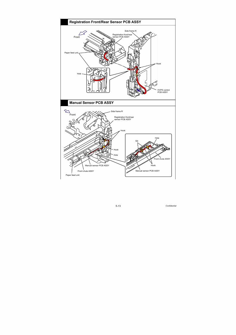
7/18/2019 Brother Mfc 9125cn 9325cw en 5694 Mfp Sm
http://slidepdf.com/reader/full/brother-mfc-9125cn-9325cw-en-5694-mfp-sm 240/597
5-13 Confidential
2 Registration Front/Rear Sensor PCB ASSY
3 Manual Sensor PCB ASSY
Hole
Front
Hook
HVPS controlPCB ASSY
Registration front/rear
sensor PCB ASSY
Side frame R
Paper feed unit
Front
Side frame R
Registration front/rearsensor PCB ASSY
Hook
Hook
Slit
Hole
Manual sensor PCB ASSY
Front chute ASSY
Front chute ASSY
Manual sensor PCB ASSY
Paper feed unit
Hook
Hole
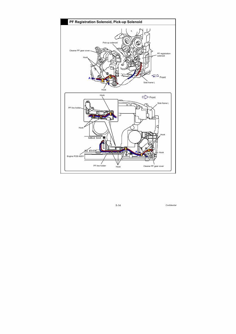
7/18/2019 Brother Mfc 9125cn 9325cw en 5694 Mfp Sm
http://slidepdf.com/reader/full/brother-mfc-9125cn-9325cw-en-5694-mfp-sm 241/597
5-14 Confidential
4 PF Registration Solenoid, Pick-up Solenoid
Pick-up solenoid
PF registrationsolenoid
Side frame L
Front
Cleaner PF gear cover
Hook
Hook
Front
Side frame L
Hook
Hook
Hook
Hook
Cleaner PF gear cover PF line holder
Engine PCB ASSY
PF line holder
A
A
Hook

7/18/2019 Brother Mfc 9125cn 9325cw en 5694 Mfp Sm
http://slidepdf.com/reader/full/brother-mfc-9125cn-9325cw-en-5694-mfp-sm 242/597
5-15 Confidential
5 Belt Drive ASSY
6 Develop Release Motor ASSY
Belt drive ASSY
Engine PCB ASSY
Front
Engine insulation sheet
Engine insulation sheetSide frame L
Hook
Hook
Front
Side frame L
Hook
Hook
HookHookEngine PCB ASSY
PF line holder
PF line holder
Develop releasemotor ASSY

7/18/2019 Brother Mfc 9125cn 9325cw en 5694 Mfp Sm
http://slidepdf.com/reader/full/brother-mfc-9125cn-9325cw-en-5694-mfp-sm 243/597
5-16 Confidential
7 Drum Motor Origin Sensor PCB ASSY
8 Fuser/Eject Drive Motor, Fuser/Eject Drive Motor Sensor
PCB ASSY
Drum motor origin sensor PCB ASSY Hook
Hole Front
Side frame L
Engine insulationsheet
Engine PCB ASSY
Engine insulationsheet
Hook
Core
Front
Hook
Engine insulation sheet
Hook
Hook
Side frame L
Engine PCB ASSYEngine insulation sheet
Eject gear cover Fuser/eject drive motorsensor PCB ASSY
Fuser/ejectdrive motor

7/18/2019 Brother Mfc 9125cn 9325cw en 5694 Mfp Sm
http://slidepdf.com/reader/full/brother-mfc-9125cn-9325cw-en-5694-mfp-sm 244/597
5-17 Confidential
9 Toner/New Sensor PCB ASSY
10 Paper Feed Motor ASSY, Drum Drive Motor
Hook
Hook
Hook
Hook
Engine PCB ASSY
Toner/New sensor PCB ASSY
Front Side frame L
Line holder M
Engine PCB ASSY
Line holder M
Line holder M
Hook
Guide
Drum drive motor Hook
Line holder M
Hook
PF line holder
Front
Paper feed
motor ASSY
Side frame L
PF line holder
HookEngine PCB ASSY
Hook
Hook

7/18/2019 Brother Mfc 9125cn 9325cw en 5694 Mfp Sm
http://slidepdf.com/reader/full/brother-mfc-9125cn-9325cw-en-5694-mfp-sm 245/597
5-18 Confidential
11 Eject Rear Sensor PCB ASSY
12 Eject Front Sensor PCB ASSY
HookHook
SlitSlit
Hole
Hole
FrontFront
A
A
Eject rear sensor
PCB ASSY
Eject rear sensorPCB ASSY
Paper eject guide
Side frame R
Side frame L
Lower air duct
Main PCB ASSY
Hook
Side frame L
Side frame L
Front
Main PCB ASSY
Front
Hook
Hole
Belt drive ASSYFuser eject drive ASSY
Eject front sensorPCB ASSY
A
A

7/18/2019 Brother Mfc 9125cn 9325cw en 5694 Mfp Sm
http://slidepdf.com/reader/full/brother-mfc-9125cn-9325cw-en-5694-mfp-sm 246/597

7/18/2019 Brother Mfc 9125cn 9325cw en 5694 Mfp Sm
http://slidepdf.com/reader/full/brother-mfc-9125cn-9325cw-en-5694-mfp-sm 247/597
5-20 Confidential
14 Main Fan ASSY, LV Fan ASSY
15 Develop Release Sensor PCB ASSY, Top Cover Open Switch,
Toner LED PCB ASSY
Side frame R
Hook
Hook
Hook
Main fan ASSY
LV fan ASSY
High-voltage power supplyPCB ASSY
Front
HookHook
Hook
Side frame R
Top cover open switch
Toner LED PCB ASSY
HVPS control PCB ASSY
Develop release sensorPCB ASSY
Front
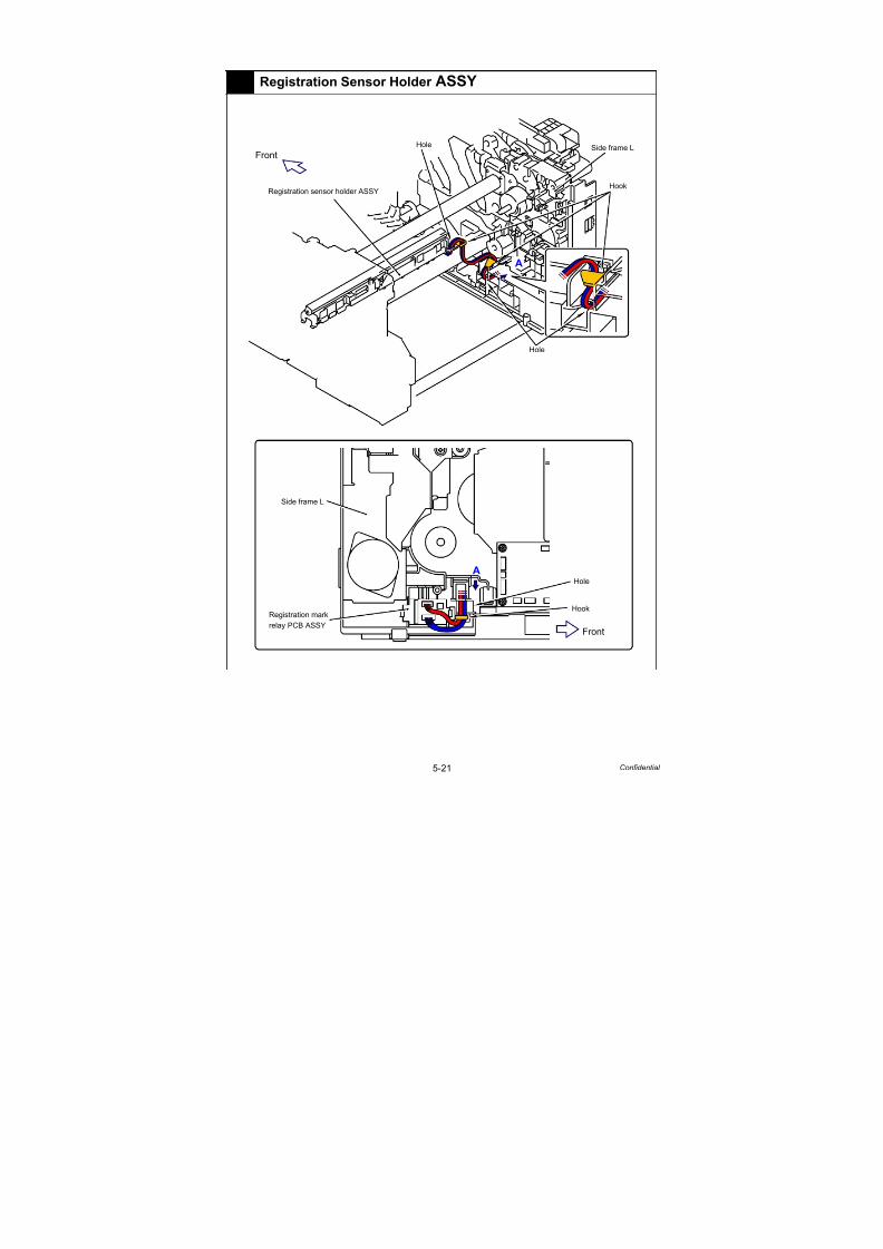
7/18/2019 Brother Mfc 9125cn 9325cw en 5694 Mfp Sm
http://slidepdf.com/reader/full/brother-mfc-9125cn-9325cw-en-5694-mfp-sm 248/597
5-21 Confidential
16 Registration Sensor Holder ASSY
Registration sensor holder ASSY
Front
Side frame L
Hole
Front
Registration mark
relay PCB ASSY
A
Hook
Hook
Hole
Hole
Side frame L
A

7/18/2019 Brother Mfc 9125cn 9325cw en 5694 Mfp Sm
http://slidepdf.com/reader/full/brother-mfc-9125cn-9325cw-en-5694-mfp-sm 249/597
5-22 Confidential
17 Low-voltage Power Supply PCB ASSY
18 Back Cover Sensor
Front
Front
A
A
Hook
Hook
Eject gear cover Side frame L
Side frame L
Hole
Low-voltage power supply PCB ASSY
LVPS cover Hole
Main PCB ASSY
Engine PCB ASSY
Engine insulationsheet
Front
Slit
HookHook
Side frame LMain PCB ASSY
Back cover sensor
Side frame L
Back cover sensor
Front
<A view> A view
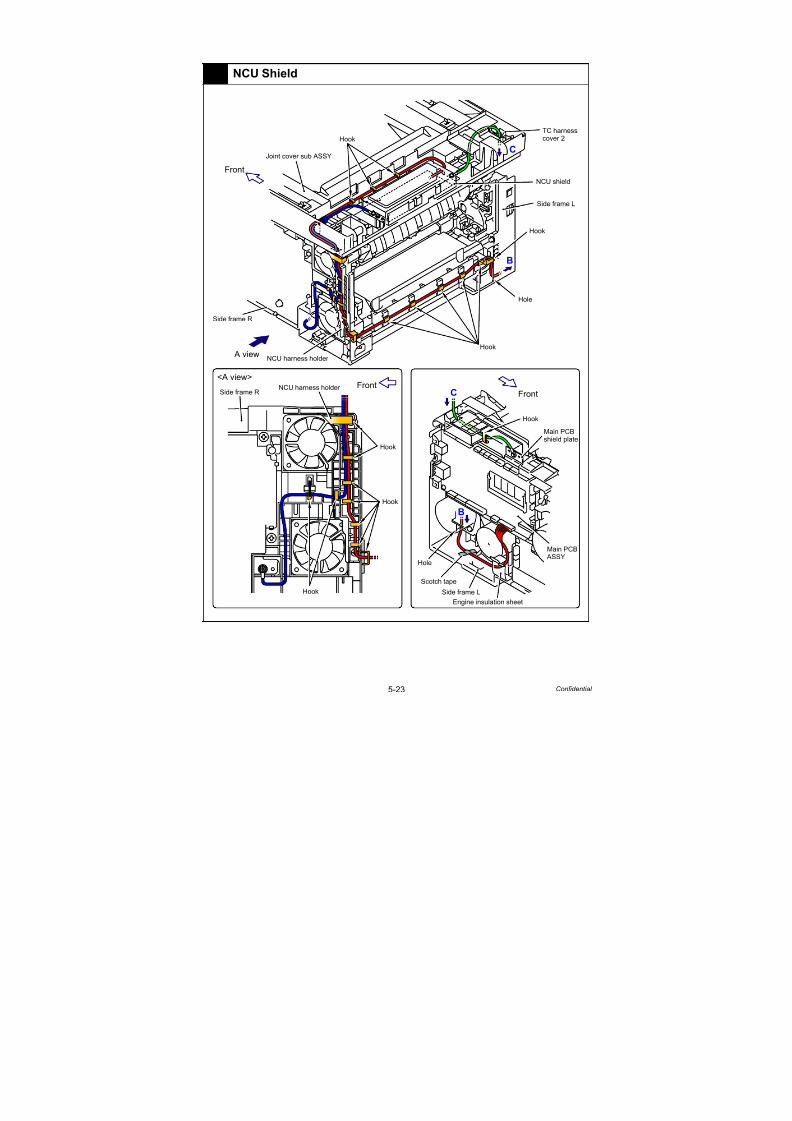
7/18/2019 Brother Mfc 9125cn 9325cw en 5694 Mfp Sm
http://slidepdf.com/reader/full/brother-mfc-9125cn-9325cw-en-5694-mfp-sm 250/597
5-23 Confidential
19 NCU Shield
Front
Hook
Front<A view>
A view
Hook
Hook
Hook
Hook
Hook
Side frame RNCU harness holder
Side frame R
Hole
B
B
C
C
TC harnesscover 2
NCU shield
Side frame L
Hook
Joint cover sub ASSY
Front
Hole
Side frame L
Engine insulation sheet
Main PCBshield plate
NCU harness holder
Main PCB ASSY
Scotch tape

7/18/2019 Brother Mfc 9125cn 9325cw en 5694 Mfp Sm
http://slidepdf.com/reader/full/brother-mfc-9125cn-9325cw-en-5694-mfp-sm 251/597
5-24 Confidential
20 ADF Unit
<A view>
ADF motor
Hook ADF unit
ADF sensor PCB ASSY
Hole
Hook ADF motor
ADF unit
Document scanner unit
Hole
Hook
ADF sensor PCB ASSY
Front
Joint cover sub ASSY
TC harness cover 2
Hook
Main PCB shield plate
Side frame L
A view

7/18/2019 Brother Mfc 9125cn 9325cw en 5694 Mfp Sm
http://slidepdf.com/reader/full/brother-mfc-9125cn-9325cw-en-5694-mfp-sm 252/597
5-25 Confidential
21 Document Scanner Unit
Document scanner unit
Hole
HookJoint cover sub ASSY
Hole
Joint coversub ASSY
TC harness cover 2Side frame L
Slit
Hook
Main PCB harness film 1
Core Main PCBharness film 1
Main shield cover plate ASSY
Front
Main PCB
shield plate
Main PCB ASSY
Side frame L
CIS harnesshold plate

7/18/2019 Brother Mfc 9125cn 9325cw en 5694 Mfp Sm
http://slidepdf.com/reader/full/brother-mfc-9125cn-9325cw-en-5694-mfp-sm 253/597
5-26 Confidential
22 Panel Unit
Panel unit
Document scanner unit
Hole
Joint cover sub ASSY
TC harnesscover 2
Hook
Front
Hook
Main PCB ASSY
Side frame L
Panel PCB ASSY
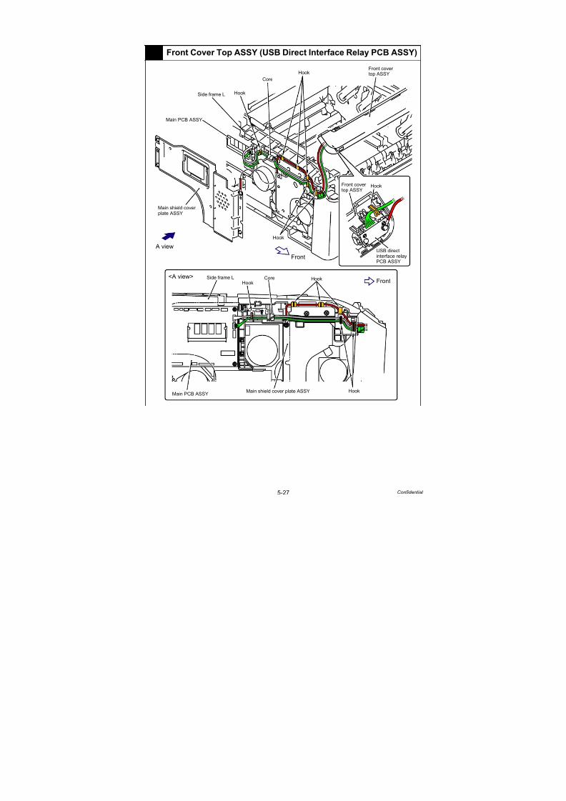
7/18/2019 Brother Mfc 9125cn 9325cw en 5694 Mfp Sm
http://slidepdf.com/reader/full/brother-mfc-9125cn-9325cw-en-5694-mfp-sm 254/597
5-27 Confidential
23 Front Cover Top ASSY (USB Direct Interface Relay PCB ASSY)
Front
Hook
Front
Front cover top ASSYHook
Hook
Core
HookHook
HookMain shield cover plate ASSY
CoreSide frame L
Side frame L
Main PCB ASSY
Main shield cover
HookFront cover top ASSY
<A view>
A view
Main PCB ASSY
plate ASSY
USB directinterface relayPCB ASSY

7/18/2019 Brother Mfc 9125cn 9325cw en 5694 Mfp Sm
http://slidepdf.com/reader/full/brother-mfc-9125cn-9325cw-en-5694-mfp-sm 255/597
5-28 Confidential
24 Front Cover Top ASSY (Wireless LAN PCB ASSY, Speaker Unit)
A
<A view>
A view
Front
Front
Rib Rib
HookHook
Hook
Hook
Hook
Hook
Hook
Hook
Hook
Speaker unit
Front cover top ASSY
Front covertop ASSY
Wireless LANPCB ASSY
Hook
Panel harnessprotective sheet
Front covertop ASSY
Side frame L
Core
Core HookMain PCB ASSY
Main PCB ASSY
Rib
Side frame L
A
B
B
B
Hook

7/18/2019 Brother Mfc 9125cn 9325cw en 5694 Mfp Sm
http://slidepdf.com/reader/full/brother-mfc-9125cn-9325cw-en-5694-mfp-sm 256/597
5-29 Confidential
25 HVPS Control PCB ASSY
Front
<A view>
A view
Hook
Main PCB ASSY
Hook
HookSide frame R
Front cover top ASSY
Side frame L
Hook
Engine PCB ASSY
Side frame R
Hook
FrontFrontEngine PCB ASSY
Hook
HookSide frame LMain PCB ASSY Rib
HVPS controlPCB ASSY
A
A

7/18/2019 Brother Mfc 9125cn 9325cw en 5694 Mfp Sm
http://slidepdf.com/reader/full/brother-mfc-9125cn-9325cw-en-5694-mfp-sm 257/597
5-30 Confidential
7. DISASSEMBLY FLOW
Paper Tray
5s/5s
Paper Stopper
10s/10s
Cord Hook
8.1 10s/10s
EXT Cap
8.2 5s/5s
Roller Holder ASSY
8.3 15s/30s
Separation Pad ASSY
8.4 5s/10s
Document Stopper
8.22 15s/15s
FB Lock Lever L/R
8.34 30s/30s
Side Cover L ASSY/ Access Cover
8.9 30s/30s
Main PCB ASSY
8.54 50s/55s
Main PCB ShieldPlate
8.57 15s/15s
Fuser/Eject DriveMotor Sensor PCB ASSY
8.70 20s/20s
Belt Drive ASSY
8.78 15s/15s
Drum Motor Origin Sensor PCB ASSY
8.79 15s/15s
Drum DevelopDrive Unit
8.60 70s/75s
Paper Feed Unit
8.63 60s/60s
Develop DriveMotor
8.61 15s/15s
Paper Feed Motor ASSY
8.62 15s/15s
Toner/New SensorPCB ASSY
8.77 30s/30s
RegistrationFront/Rear SensorPCB ASSY
8.64 25s/25s
Manual SensorPCB ASSY
8.65 30s/30s
Fuser/Eject DriveMotor
8.69 15s/15s
Engine ShieldPlate
8.58 10s/10s
Engine PCB ASSY
8.55 40s/45s
Battery ASSY
8.31 5s/5s
Registration
Mark Relay PCB ASSY
8.59 25s/25s
Main PCBInsulation Sheet /Engine InsulationSheet
8.56 10s/15s
A
B
C
F
E
Pick-up SectorGear Spring/Friction Spring
8.66 40s/40s
PF RegistrationSolenoid
8.67 15s/25s
Pick-up Solenoid/
Pick-up SolenoidLever Spring
8.68 20s/35s
Control PanelCover ASSY
8.25 10s/10s
Panel PCB ASSY
8.27 15s/15s
Top DressCover L/R
8.33 15s/15s
Joint Cover LockSpring/Joint Cover LockLever
8.35 10s/15s
Rubber Key L/R
8.28 5s/5s
LCD/
LCD Cover
8.29 30s/30s
DocumentScanner Unit
8.26 10s/10s
Pull Arm L/Pull Arm R/Pull Arm Spring
8.11 10s/10s
Pull Arm Guide/Lock claw
8.32 10s/10s
TC Arm Spring
8.42 20s/20s
Top Cover Arm L
8.72 10s/10s
Top Cover Arm R
8.71 10s/10s
Arm Guide LCover
8.43 10s/10s
Disassembly / Re-Assembly (second)

7/18/2019 Brother Mfc 9125cn 9325cw en 5694 Mfp Sm
http://slidepdf.com/reader/full/brother-mfc-9125cn-9325cw-en-5694-mfp-sm 258/597
5-31 Confidential
Disassembly / Re-Assembly (second)
ADF Unit
8.12 15s/20s
Hinge ASSY L
8.12 10s/10s
Joint Cover Sub ASSY
8.44 25s/30s
Inner Chute ASSY 2
8.45 15s/15s8.47 15s/15s
FFC Harness:MAIN-LED CTL
8.48 85s/90s
LED HeadControl PCB ASSY
8.50 40s/40s
LED ASSY
8.51 75s/75s
LV Fan ASSY
8.80 40s/50s
Low-voltagePower SupplyPCB ASSY
8.82 100s/100s
RegistrationSensor Holder ASSY
8.83 30s/30s
Main Fan ASSY
8.81 10s/10s
Waste Toner Sensor
8.86 25s/25s
Manual Feed Slot ASSY
8.41 5s/5s
Front Cover
8.40 40s/40s
Speaker Unit/Front Cover TopBase
8.39 10s/10s
USB DirectInterface RelayPCB ASSY(USB DirectInterface modelonly)
8.37 20s/20s
Panel GrpundPlate 2 (Only themodels withoutthe USB directinterface)
8.38 25s/25s
Front Cover Top ASSY/Wireless LANPCB ASSY(Wireless LANmodel only)
8.36 30s/30s
Z Spring L/Z Spring R
8.52 20s/20s
ADF Cover ASSY
8.14 5s/5s
Gear Cover
8.15 5s/5s
SeparationRoller Shaft ASSY
8.16 10s/10s
Upper DocumentChute ASSY
8.17 25s/25s
LED Power RelayPCB ASSY
8.49 5s/5s
Paper Stack Lever ASSY
TC ReleaseLeber
8.46 15s/15s
Hinge R/Hinge R Support/Hinge Base
8.13 15s/15s Air Filter Holder ASSY/Ozone Filter
8.73 35s/35s
Side Cover R ASSY
8.10 15s/15s
Paper Eject Rear Actuator/Paper Eject Rear Actuator Spring/Paper Eject Rear Actuator Top
8.74 35s/35s
Eject Rear SensorPCB ASSY
8.75 5s/5s
Back Cover/Back CoverStopper L/R
8.5 15s/15s
Fuser Cover
8.6 5s/5s
Paper EjectFront Actuator
8.7 10s/15s
Fuser Unit
8.8 50s/45s
Eject FrontSensor PCB ASSY
8.76 5s/5s
NCU PCB ASSY(NCU model only)
8.30 15s/15s
Develop ReleaseMotor ASSY
8.53 15s/15s
BD
D
C
E
G
G F
A
SeparationRubber ASSY
8.18 5s/10s
Drive Frame ASSY
8.22 25s/25s
Document Hold
ASSY
8.24 10s/10s
Paper FeedRoller ASSY
8.19 10s/10s
Ejection Roller ASSY
8.20 10s/10s
High-voltagePower Supply PCB ASSY
8.84 40s/40s
Side Frame R
50s/45s
Belt Cleaner Spring
8.88 80s/100s
TR Head Spring
8.89 30s/40s
HVPS ControlPCB ASSY
8.85 15s/15s
DevelopRelease Sensor PCB ASSY
8.87 5s/5s8.90
Toner LED PCB ASSY/LED Holder
8.91 30s/30s
LM Hook B/LM Hook C/Hook Spring BC10
8.92 50s/55s
ADF Sensor PCB ASSY
8.21 15s/15s
Paper StackLever
8.23 10s/10s

7/18/2019 Brother Mfc 9125cn 9325cw en 5694 Mfp Sm
http://slidepdf.com/reader/full/brother-mfc-9125cn-9325cw-en-5694-mfp-sm 259/597
5-32 Confidential
8. DISASSEMBLY PROCEDURE
Preparation
Prior to proceeding with the disassembly procedure,
(1) Unplug
- the AC cord,
- the modular jack of the telephone line,
- the USB cable, if connected,
- the LAN cable, if connected,
- the USB cable for PictBridge or USB flash memory drive, if connected, and
- the modular jack of the external telephone set if connected.
(2) Remove
- the Paper tray,
- the Toner cartridge,
- the Drum unit,
- the Belt unit, and
- the Waste toner box.
Toner cartridge, Drum unit
Belt unit
Waste toner box
Paper tray

7/18/2019 Brother Mfc 9125cn 9325cw en 5694 Mfp Sm
http://slidepdf.com/reader/full/brother-mfc-9125cn-9325cw-en-5694-mfp-sm 260/597
5-33 Confidential
8.1 Cord Hook
(1) Remove the two Taptite cup B M3x8 screws, and then remove the two Cord hook from the
Document scanner unit.
Fig. 5-1
Document scanner unit
Taptite cup B M3x8
Cord hook
Taptite cup B M3x8
Cord hook
<Back side>
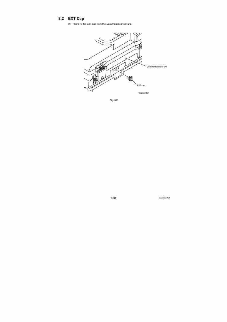
7/18/2019 Brother Mfc 9125cn 9325cw en 5694 Mfp Sm
http://slidepdf.com/reader/full/brother-mfc-9125cn-9325cw-en-5694-mfp-sm 261/597
5-34 Confidential
8.2 EXT Cap
(1) Remove the EXT cap from the Document scanner unit.
Fig. 5-2
Document scanner unit
EXT cap
<Back side>

7/18/2019 Brother Mfc 9125cn 9325cw en 5694 Mfp Sm
http://slidepdf.com/reader/full/brother-mfc-9125cn-9325cw-en-5694-mfp-sm 262/597
5-35 Confidential
8.3 Roller Holder ASSY
(1) Push the Lift arm to the back and remove “B” of the Roller holder ASSY from “A” of the Lift
arm, and the Roller holder ASSY rotates in the direction of the arrow 1b.
Fig. 5-3
(2) Slide the Roller holder ASSY in the direction of the arrow 2 and remove it from “C” of the
Paper feed unit.
(3) Slide the Roller holder ASSY in the direction of the arrows 3a and 3b in this order and
remove it from the Paper feed unit.
Fig. 5-4
Lift arm
Lift arm
“A”
Roller holder
“B”Paper feed unit
“B”
Roller holder ASSY
Paper feed unit
“A”
1a
1b
1a
1b ASSY
<Front>
Paper feed unit
“C”
Roller holder ASSY
23a
3b

7/18/2019 Brother Mfc 9125cn 9325cw en 5694 Mfp Sm
http://slidepdf.com/reader/full/brother-mfc-9125cn-9325cw-en-5694-mfp-sm 263/597
5-36 Confidential
Fig. 5-5
Assembling Note:
When assembling the Roller holder ASSY onto the Paper feed unit, make sure to align the
Shaft of the Roller holder ASSY with the Hole of the Paper feed unit, and then insert it into
the Hole.
Roller holder ASSY
Paper feed unit
Paper feed unit
Shaft
Hole
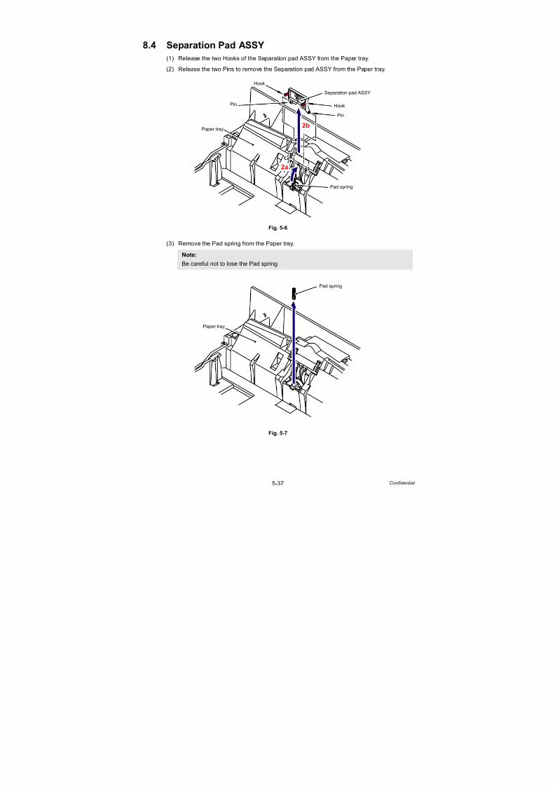
7/18/2019 Brother Mfc 9125cn 9325cw en 5694 Mfp Sm
http://slidepdf.com/reader/full/brother-mfc-9125cn-9325cw-en-5694-mfp-sm 264/597
5-37 Confidential
8.4 Separation Pad ASSY
(1) Release the two Hooks of the Separation pad ASSY from the Paper tray.
(2) Release the two Pins to remove the Separation pad ASSY from the Paper tray.
Fig. 5-6
(3) Remove the Pad spring from the Paper tray.
Fig. 5-7
Note:
Be careful not to lose the Pad spring.
Paper tray
Separation pad ASSY
Hook
Pin
Hook
Pin
2a
2b
Pad spring
Paper tray
Pad spring

7/18/2019 Brother Mfc 9125cn 9325cw en 5694 Mfp Sm
http://slidepdf.com/reader/full/brother-mfc-9125cn-9325cw-en-5694-mfp-sm 265/597
5-38 Confidential
Fig. 5-8
Assembling Note:
Make sure to assemble the Separation pad ASSY in a way that the “A” of the Separation
pad ASSY fits into the “B” of the Pad spring.
Separation pad ASSY
“A”
Pad spring
“B”

7/18/2019 Brother Mfc 9125cn 9325cw en 5694 Mfp Sm
http://slidepdf.com/reader/full/brother-mfc-9125cn-9325cw-en-5694-mfp-sm 266/597
5-39 Confidential
8.5 Back Cover/Back Cover Stopper L/R
(1) Open the Back cover.
Fig. 5-9
(2) Release the Hook to remove the Back cover stopper L and R from the Main body.
Fig. 5-10
Back cover
<Back side>
Hook
Back cover stopper L
Back cover stopper R
Back cover
Main body
<Back side>

7/18/2019 Brother Mfc 9125cn 9325cw en 5694 Mfp Sm
http://slidepdf.com/reader/full/brother-mfc-9125cn-9325cw-en-5694-mfp-sm 267/597
5-40 Confidential
(3) Remove the Bush of the Back cover from the Shaft at the right side of the Main body.
Fig. 5-11
(4) Remove the Back cover from the Shaft at the left side of the Main body.
Fig. 5-12
Main body
Back cover
Bush
Bush
Shaft
Shaft
<Right side>
<Back side>
3a
3c
3b
Main body
Shaft
Back cover
<Left side>
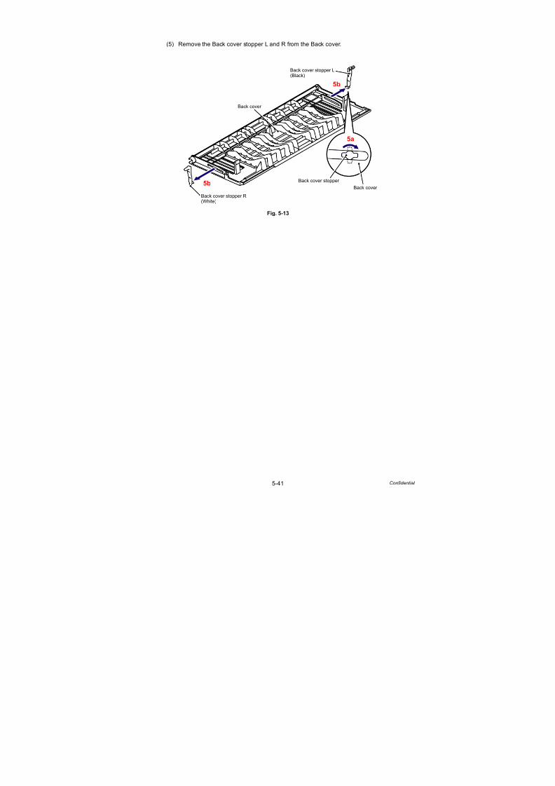
7/18/2019 Brother Mfc 9125cn 9325cw en 5694 Mfp Sm
http://slidepdf.com/reader/full/brother-mfc-9125cn-9325cw-en-5694-mfp-sm 268/597
5-41 Confidential
(5) Remove the Back cover stopper L and R from the Back cover.
Fig. 5-13
Back cover
Back cover stopper L
Back cover stopper R
Back cover stopper
Back cover
5a
5b
5b
(Black)
(White)
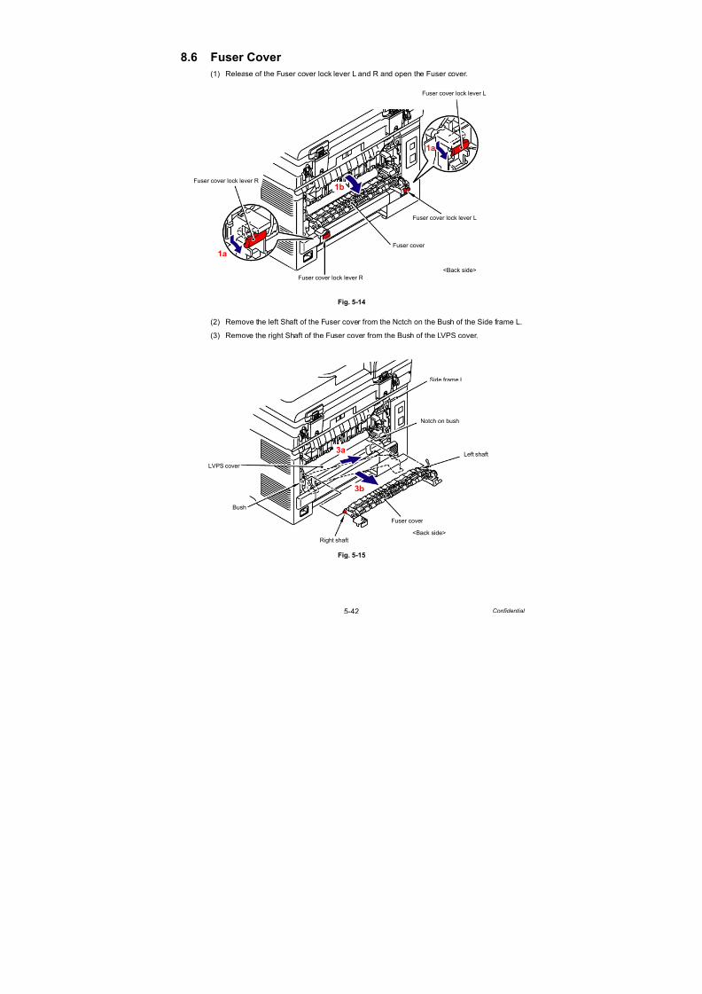
7/18/2019 Brother Mfc 9125cn 9325cw en 5694 Mfp Sm
http://slidepdf.com/reader/full/brother-mfc-9125cn-9325cw-en-5694-mfp-sm 269/597
5-42 Confidential
8.6 Fuser Cover
(1) Release of the Fuser cover lock lever L and R and open the Fuser cover.
Fig. 5-14
(2) Remove the left Shaft of the Fuser cover from the Notch on the Bush of the Side frame L.
(3) Remove the right Shaft of the Fuser cover from the Bush of the LVPS cover.
Fig. 5-15
Fuser cover lock lever L
Fuser cover
Fuser cover lock lever R
1a
1a
1b
<Back side>
Fuser cover lock lever L
Fuser cover lock lever R
Side frame L
Bush
Left shaft
LVPS cover
Notch on bush
Fuser cover
Right shaft
3a
3b
<Back side>
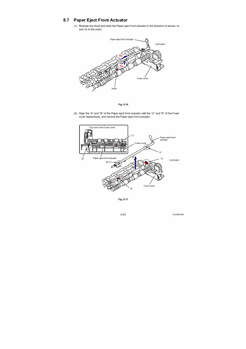
7/18/2019 Brother Mfc 9125cn 9325cw en 5694 Mfp Sm
http://slidepdf.com/reader/full/brother-mfc-9125cn-9325cw-en-5694-mfp-sm 270/597
5-43 Confidential
8.7 Paper Eject Front Actuator
(1) Release the Hook and slide the Paper eject front actuator in the direction of arrows 1a
and 1b in this order.
Fig. 5-16
(2) Align the “A” and “B” of the Paper eject front actuator with the “C” and “D” of the Fuser
cover respectively, and remove the Paper eject front actuator.
Fig. 5-17
Fuser cover
Hook
Paper eject front actuator
1a
1b
<Left side>
Paper eject front
“A”
“B”
Fuser cover
“C”
“D”
Fuser cover
Paper eject front actuator
“C”
“D”<Left side>
* Top view of the Fuser cover
actuator
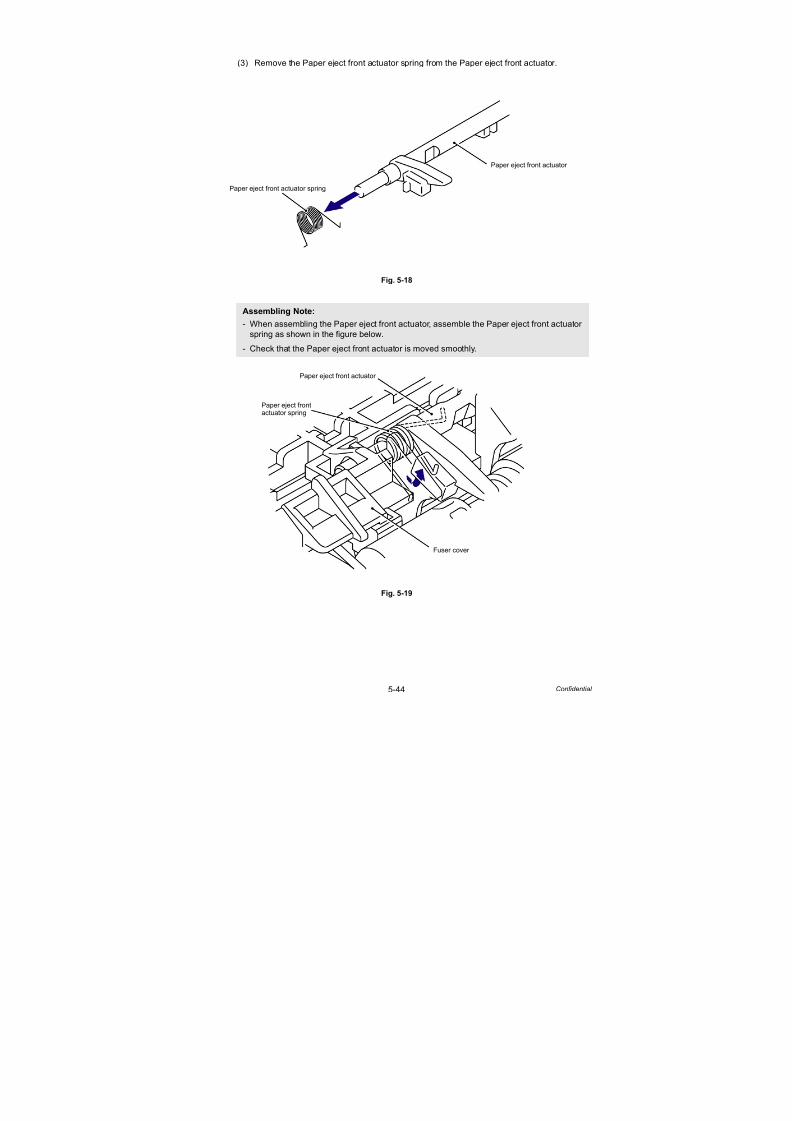
7/18/2019 Brother Mfc 9125cn 9325cw en 5694 Mfp Sm
http://slidepdf.com/reader/full/brother-mfc-9125cn-9325cw-en-5694-mfp-sm 271/597
5-44 Confidential
(3) Remove the Paper eject front actuator spring from the Paper eject front actuator.
Fig. 5-18
Fig. 5-19
Assembling Note:
- When assembling the Paper eject front actuator, assemble the Paper eject front actuator
spring as shown in the figure below.
- Check that the Paper eject front actuator is moved smoothly.
Paper eject front actuator
Paper eject front actuator spring
Paper eject front actuator
Fuser cover
Paper eject frontactuator spring

7/18/2019 Brother Mfc 9125cn 9325cw en 5694 Mfp Sm
http://slidepdf.com/reader/full/brother-mfc-9125cn-9325cw-en-5694-mfp-sm 272/597
5-45 Confidential
8.8 Fuser Unit
(1) Remove the Taptite bind B M3x12 screw, and then remove the Fuser cover L from the
Fuser unit.
Fig. 5-20
(2) Remove the Taptite bind B M3x12 screw, and then remove the Fuser cover R from the
Fuser unit.
Fig. 5-21
Fuser unit
Fuser cover L
Taptite bind B M3x12
<Back side>
Taptite bind B M3x12
Fuser unit
Fuser cover R
<Back side>

7/18/2019 Brother Mfc 9125cn 9325cw en 5694 Mfp Sm
http://slidepdf.com/reader/full/brother-mfc-9125cn-9325cw-en-5694-mfp-sm 273/597
5-46 Confidential
(3) Disconnect the two Connectors (CN1, CN3) from the Eject front sensor PCB ASSY.
Fig. 5-22
(4) Disconnect the two Electrode terminals from the Fuser unit.
Fig. 5-23
Connector
CN1
Eject front sensor PCB ASSY
CN1CN3
Connector
CN3
<Back side>
Electrode terminal (large)
Electrode terminal (small)
Fuser unit
<Back side>

7/18/2019 Brother Mfc 9125cn 9325cw en 5694 Mfp Sm
http://slidepdf.com/reader/full/brother-mfc-9125cn-9325cw-en-5694-mfp-sm 274/597
5-47 Confidential
(5) Remove the two Taptite pan B M4x14 screws, and then remove the Fuser unit from the
Main body as holding the “A”.
Fig. 5-24
Fig. 5-25
Note:
- Do not apply a physical impact or vibration to the Fuser unit.
- Do not touch the roller and electrodes as shown in the figure below to prevent
breakage of the Fuser unit.
Taptite pan B M4x14
Taptite pan B M4x14
Fuser unit
Main body
“A”
<Back side>
Pressure roller ASSY
Fuser unit Fuser unit
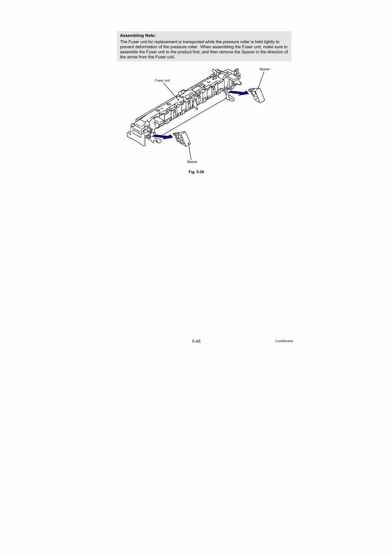
7/18/2019 Brother Mfc 9125cn 9325cw en 5694 Mfp Sm
http://slidepdf.com/reader/full/brother-mfc-9125cn-9325cw-en-5694-mfp-sm 275/597
5-48 Confidential
Fig. 5-26
Assembling Note:
The Fuser unit for replacement is transported while the pressure roller is held lightly to
prevent deformation of the pressure roller. When assembling the Fuser unit, make sure to
assemble the Fuser unit to the product first, and then remove the Spacer in the direction of
the arrow from the Fuser unit.
Fuser unit
Spacer
Spacer

7/18/2019 Brother Mfc 9125cn 9325cw en 5694 Mfp Sm
http://slidepdf.com/reader/full/brother-mfc-9125cn-9325cw-en-5694-mfp-sm 276/597
5-49 Confidential
8.9 Side Cover L ASSY/Access Cover
(1) Open the Joint cover sub ASSY as pushing up the TC release lever.
Fig. 5-27
TC release lever
Joint cover sub ASSY
1a
1b

7/18/2019 Brother Mfc 9125cn 9325cw en 5694 Mfp Sm
http://slidepdf.com/reader/full/brother-mfc-9125cn-9325cw-en-5694-mfp-sm 277/597
5-50 Confidential
(2) Remove the two Taptite bind B M4x12 screws from the Side cover L ASSY.
(3) Release the two Hooks and two Bosses on the upper side and four Hooks on the bottom,
and then remove the Side cover L ASSY from the Main body.
Fig. 5-28
Taptite bind B M4x12
Hook
Boss
Main bodySide cover L ASSY
Taptite bind B M4x12Boss
Hook
3a
3b
<Left side>
Side cover L ASSYHook
HookHook
* Inside of Side cover L ASSY
<Front><Back side>

7/18/2019 Brother Mfc 9125cn 9325cw en 5694 Mfp Sm
http://slidepdf.com/reader/full/brother-mfc-9125cn-9325cw-en-5694-mfp-sm 278/597
5-51 Confidential
Fig. 5-29
(4) Remove the Access cover from the Side cover L ASSY.
Fig. 5-29-1
Assembling Note:
- When assembling the Side cover L ASSY onto the Main body, make sure to push the
three Hooks of the Front cover into the three “A” of the Side cover L ASSY.
- If the scotch tape to fix the NCU harness is peeled off when assembling the Side cover L
ASSY, make sure to re-affix the tape before assembling the side cover L ASSY. If the
scotch tape is peeled off, the Side cover L ASSY may bite the NCU harness.
Side cover L ASSY
Front cover
“A”Hook
<Left side>
Side cover L ASSY
Access cover
4a
4b

7/18/2019 Brother Mfc 9125cn 9325cw en 5694 Mfp Sm
http://slidepdf.com/reader/full/brother-mfc-9125cn-9325cw-en-5694-mfp-sm 279/597
5-52 Confidential
8.10 Side Cover R ASSY
(1) Remove the two Taptite bind B M4x12 screws from the Side cover R ASSY.
(2) Release the two Hooks and two Bosses on the upper side and four Hooks on the bottom,
and then remove the Side cover R ASSY from the Main body.
Fig. 5-30
Taptite bind B M4x12
Hook
Main body
Side cover R ASSY
Taptite bind B M4x12
Boss
Boss
<Right side>
* Inside of Side cover R ASSY
<Front><Back side>
Side cover R ASSY
Hook
HookHook

7/18/2019 Brother Mfc 9125cn 9325cw en 5694 Mfp Sm
http://slidepdf.com/reader/full/brother-mfc-9125cn-9325cw-en-5694-mfp-sm 280/597
5-53 Confidential
Fig. 5-31
Assembling Note:
When assembling the Side cover R ASSY onto the Main body, make sure to push the three
Hooks of the Front cover into the three “A” of the Side cover R ASSY.
Side cover R ASSY
Front cover
“A”
Hook
<Right side>
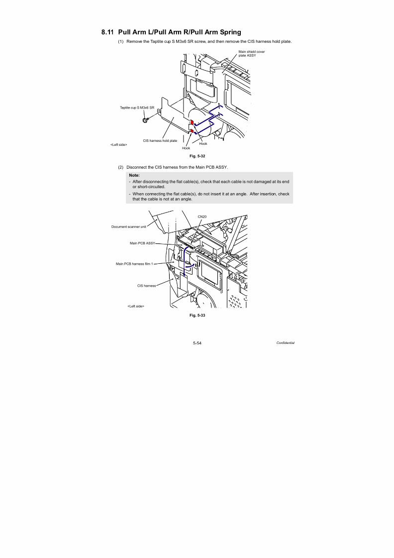
7/18/2019 Brother Mfc 9125cn 9325cw en 5694 Mfp Sm
http://slidepdf.com/reader/full/brother-mfc-9125cn-9325cw-en-5694-mfp-sm 281/597
5-54 Confidential
8.11 Pull Arm L/Pull Arm R/Pull Arm Spring
(1) Remove the Taptite cup S M3x6 SR screw, and then remove the CIS harness hold plate.
Fig. 5-32
(2) Disconnect the CIS harness from the Main PCB ASSY.
Fig. 5-33
Note:
- After disconnecting the flat cable(s), check that each cable is not damaged at its end
or short-circuited.- When connecting the flat cable(s), do not insert it at an angle. After insertion, check
that the cable is not at an angle.
CIS harness hold plate
<Left side> Hook
Hook
Taptite cup S M3x6 SR
Main shield coverplate ASSY
CN20
CIS harness
Document scanner unit
Main PCB ASSY
Main PCB harness film 1
<Left side>
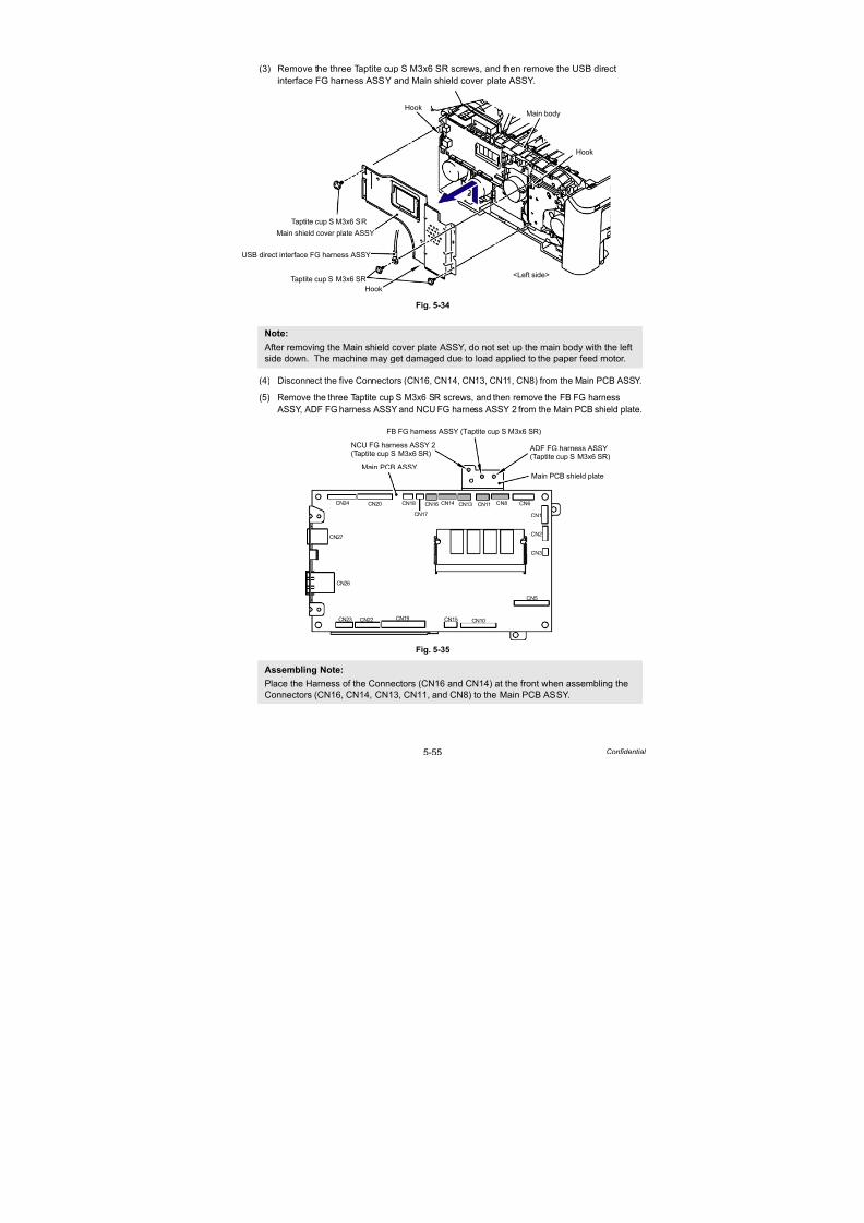
7/18/2019 Brother Mfc 9125cn 9325cw en 5694 Mfp Sm
http://slidepdf.com/reader/full/brother-mfc-9125cn-9325cw-en-5694-mfp-sm 282/597
5-55 Confidential
(3) Remove the three Taptite cup S M3x6 SR screws, and then remove the USB direct
interface FG harness ASSY and Main shield cover plate ASSY.
Fig. 5-34
(4) Disconnect the five Connectors (CN16, CN14, CN13, CN11, CN8) from the Main PCB ASSY.
(5) Remove the three Taptite cup S M3x6 SR screws, and then remove the FB FG harness
ASSY, ADF FG harness ASSY and NCU FG harness ASSY 2 from the Main PCB shield plate.
Fig. 5-35
Note:
After removing the Main shield cover plate ASSY, do not set up the main body with the left
side down. The machine may get damaged due to load applied to the paper feed motor.
Assembling Note:
Place the Harness of the Connectors (CN16 and CN14) at the front when assembling the
Connectors (CN16, CN14, CN13, CN11, and CN8) to the Main PCB ASSY.
Main body
Taptite cup S M3x6 SR
Taptite cup S M3x6 SR
Main shield cover plate ASSY
Hook
Hook
Hook
<Left side>
USB direct interface FG harness ASSY
CN24 CN20
CN27
CN26
CN23 CN22 CN19 CN15 CN10
CN1
CN2
CN3
CN18
CN17
CN16 CN14 CN13 CN11 CN8
CN5
CN6
Main PCB ASSY
Main PCB shield plate
FB FG harness ASSY (Taptite cup S M3x6 SR)
ADF FG harness ASSY(Taptite cup S M3x6 SR)
NCU FG harness ASSY 2(Taptite cup S M3x6 SR)

7/18/2019 Brother Mfc 9125cn 9325cw en 5694 Mfp Sm
http://slidepdf.com/reader/full/brother-mfc-9125cn-9325cw-en-5694-mfp-sm 283/597
5-56 Confidential
(6) Release the FB lock lever L and FB lock lever R and open the Document scanner unit.
Fig. 5-36
(7) Release the Hooks of the Pull Arm L and Pull Arm R from the joints of the Document
scanner unit.
Fig. 5-37
FB lock lever L
FB lock lever R
Document scanner unit
Joint cover sub ASSY
<A view> <B view>
B view
6b
6a6a
A view
Document scanner unit
Pull Arm L
Pull arm R
Hook
Hook

7/18/2019 Brother Mfc 9125cn 9325cw en 5694 Mfp Sm
http://slidepdf.com/reader/full/brother-mfc-9125cn-9325cw-en-5694-mfp-sm 284/597
5-57 Confidential
(8) Remove the Pull arm L, Pull arm spring ADF L, Pull arm R and Pull arm spring ADF R
from the Pull arm guide.
Fig. 5-38
Pull arm guide
Pull arm LPull arm R
Pull arm spring ADF L
Pull arm spring ADF R
Hook
Hook
Pull arm guide

7/18/2019 Brother Mfc 9125cn 9325cw en 5694 Mfp Sm
http://slidepdf.com/reader/full/brother-mfc-9125cn-9325cw-en-5694-mfp-sm 285/597
5-58 Confidential
8.12 Hinge ASSY L
(1) Remove the Document scanner unit from the Joint cover sub ASSY.
Fig. 5-39
Harness routing: Refer to “ Document Scanner Unit.”
(2) Remove the two Taptite bind B M4x12 screws from the ADF unit.
Fig. 5-40
Joint cover sub ASSY
Document scanner unit
Document scanner unit
Joint cover sub ASSY
Shaft part of joint cover sub ASSY
1a1b
1c
ADF unit
Taptite bind B M4x12
Document scanner unit

7/18/2019 Brother Mfc 9125cn 9325cw en 5694 Mfp Sm
http://slidepdf.com/reader/full/brother-mfc-9125cn-9325cw-en-5694-mfp-sm 286/597
5-59 Confidential
(3) Open the ADF unit and lift it slightly, insert the Ferrite core of the ADF harness unit into
the hole of the Document scanner unit, and remove the ADF unit.
Fig. 5-41
Harness routing: Refer to “ ADF Unit.”
(4) Turn the ADF unit upside down.
(5) Remove the two Taptite cup B M3x10 screws and one Taptite cup S M3x12 screw, and
then remove the Hinge ASSY L from the ADF unit.
Fig. 5-42
ADF unit
ADF harness unit
Ferrite core
Document scanner unit
Hole
3a
3b
Taptite cup B M3x10
Hinge ASSY L
ADF unit
Taptite cup B M3x10
Taptite cup S M3x12

7/18/2019 Brother Mfc 9125cn 9325cw en 5694 Mfp Sm
http://slidepdf.com/reader/full/brother-mfc-9125cn-9325cw-en-5694-mfp-sm 287/597
5-60 Confidential
8.13 Hinge R/Hinge R Support/Hinge Base
(1) Remove the Taptite cup B M3x10 screw, and then remove the Hinge R support from the
Hinge R, and remove the Hinge R from the Hinge base.
Fig. 5-43
(2) Remove the three Taptite cup B M3x10 screws, and then remove the Hinge base from the
ADF unit.
Fig. 5-44
Taptite cup B M3x10
Hinge R support
Hinge R
ADF unit
Hinge base
Taptite cup B M3x10
Hinge base
ADF unit

7/18/2019 Brother Mfc 9125cn 9325cw en 5694 Mfp Sm
http://slidepdf.com/reader/full/brother-mfc-9125cn-9325cw-en-5694-mfp-sm 288/597
5-61 Confidential
8.14 ADF Cover ASSY
(1) Place the ADF unit the right way up.
(2) Release the two Pins on both sides of the ADF cover ASSY to remove it while the ADF
cover ASSY being opened.
Fig. 5-45
ADF cover ASSY
Pin
Pin
ADF unit
2c
2b
2a
2a2a

7/18/2019 Brother Mfc 9125cn 9325cw en 5694 Mfp Sm
http://slidepdf.com/reader/full/brother-mfc-9125cn-9325cw-en-5694-mfp-sm 289/597
5-62 Confidential
8.15 Gear Cover
(1) Release the Ratch and Hook of the Gear cover from the bottom side of the ADF unit to
remove it.
Fig. 5-46
ADF unit
Ratch
Hook
Gear cover
ADF unit
RatchHook
Gear cover
* The positions of Hook and Ratch viewed from the bottom side of the ADF unit.
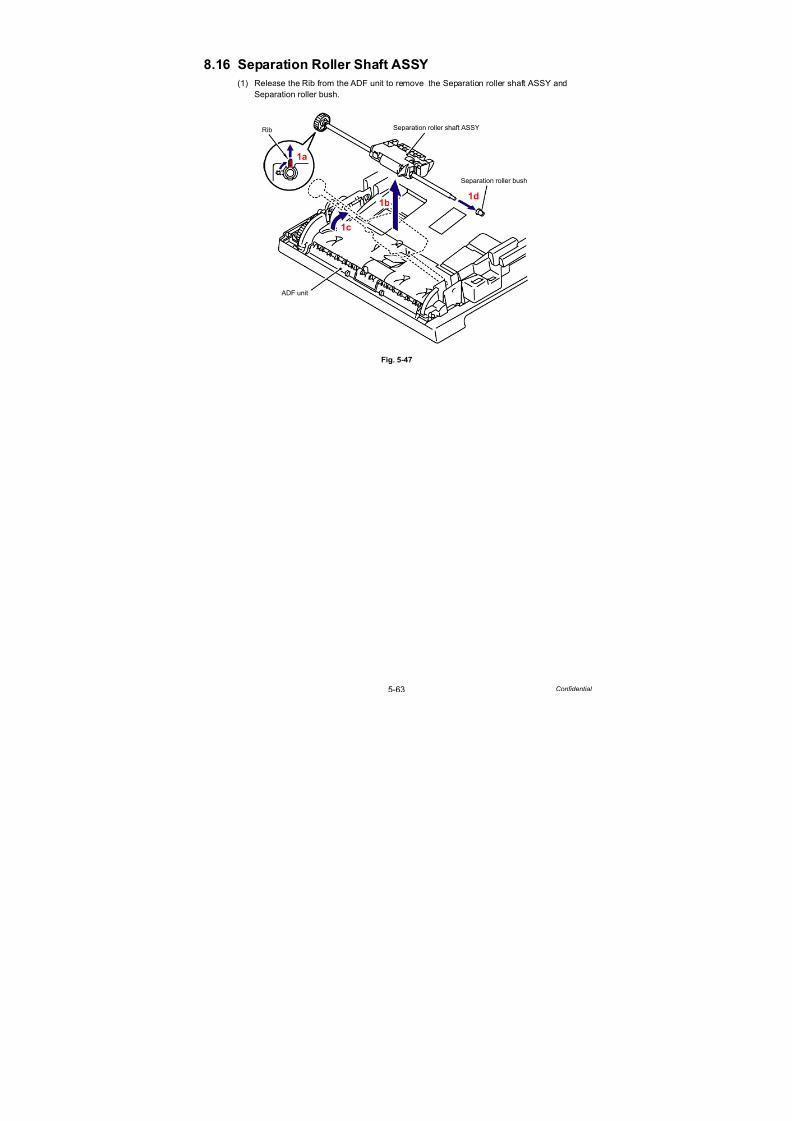
7/18/2019 Brother Mfc 9125cn 9325cw en 5694 Mfp Sm
http://slidepdf.com/reader/full/brother-mfc-9125cn-9325cw-en-5694-mfp-sm 290/597
5-63 Confidential
8.16 Separation Roller Shaft ASSY
(1) Release the Rib from the ADF unit to remove the Separation roller shaft ASSY and
Separation roller bush.
Fig. 5-47
ADF unit
Rib Separation roller shaft ASSY
Separation roller bush
1a
1b
1c
1d

7/18/2019 Brother Mfc 9125cn 9325cw en 5694 Mfp Sm
http://slidepdf.com/reader/full/brother-mfc-9125cn-9325cw-en-5694-mfp-sm 291/597
5-64 Confidential
8.17 Upper Document Chute ASSY
(1) Remove the four Taptite cup B M3x10 screws from the Upper document chute ASSY.
(2) Release the five Hooks to remove the Upper document chute ASSY.
Fig. 5-48
Taptite cup B M3x10 Taptite cup B M3x10
Hook
Upper document chute ASSY
Hook
Hook
Hook
Hook
ADF unit

7/18/2019 Brother Mfc 9125cn 9325cw en 5694 Mfp Sm
http://slidepdf.com/reader/full/brother-mfc-9125cn-9325cw-en-5694-mfp-sm 292/597
5-65 Confidential
8.18 Separation Rubber ASSY
(1) Remove the Separation rubber ASSY from the Upper document chute ASSY.
Fig. 5-49
Upper document chute ASSY
Separation rubber ASSY
Hook
Hook
“A”
“A”
“A”
ADF plate spring
1a
1b
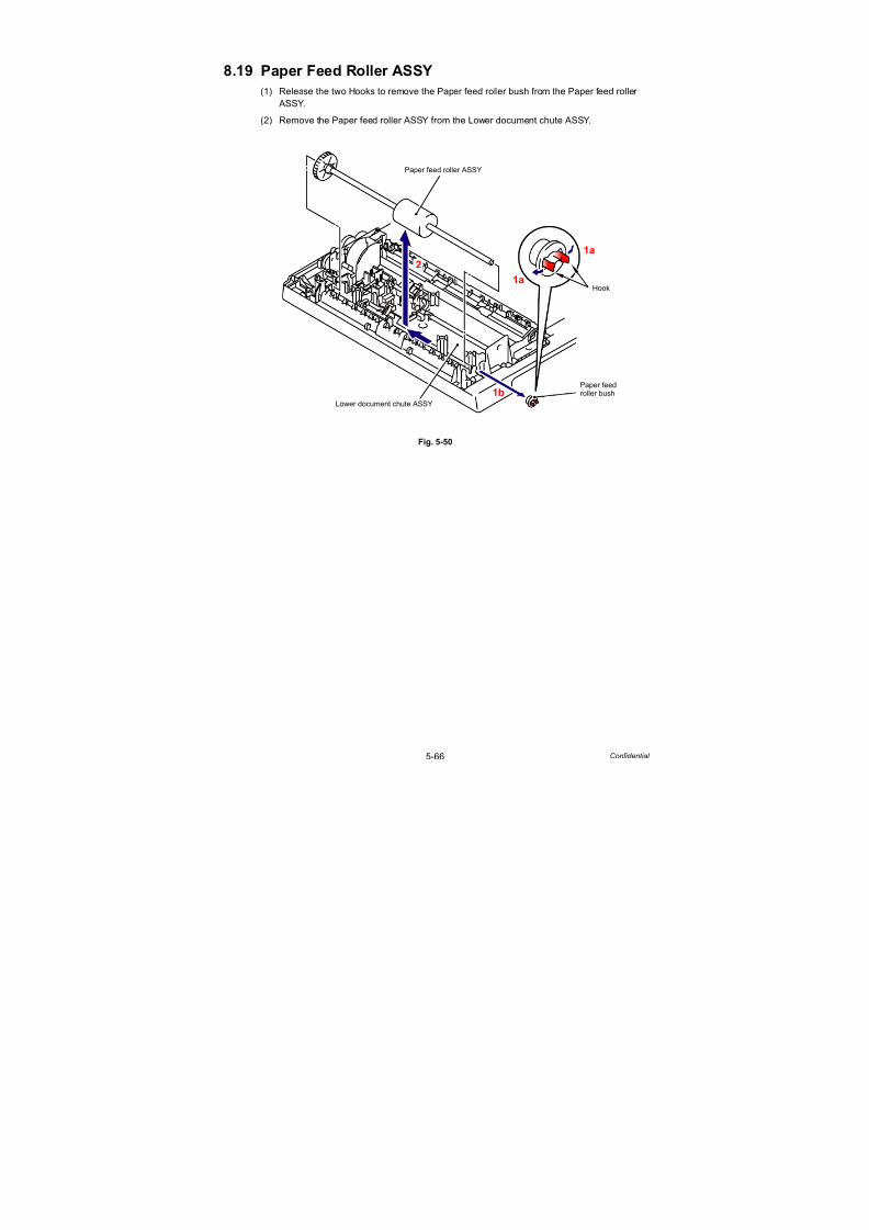
7/18/2019 Brother Mfc 9125cn 9325cw en 5694 Mfp Sm
http://slidepdf.com/reader/full/brother-mfc-9125cn-9325cw-en-5694-mfp-sm 293/597
5-66 Confidential
8.19 Paper Feed Roller ASSY
(1) Release the two Hooks to remove the Paper feed roller bush from the Paper feed roller
ASSY.
(2) Remove the Paper feed roller ASSY from the Lower document chute ASSY.
Fig. 5-50
Hook
Paper feed
Lower document chute ASSY
Paper feed roller ASSY
2
1b
1a
1a
roller bush

7/18/2019 Brother Mfc 9125cn 9325cw en 5694 Mfp Sm
http://slidepdf.com/reader/full/brother-mfc-9125cn-9325cw-en-5694-mfp-sm 294/597
5-67 Confidential
8.20 Ejection Roller ASSY
(1) Release the two Hooks A to remove the Ejection roller ASSY from the Lower document
chute ASSY.
Fig. 5-51
(2) Release the two Hooks B to remove the Ejection roller bush from the Ejection roller ASSY.
Fig. 5-51-1
Hook A
Lower document chute ASSY
Ejection roller ASSY
Ejection roller bush
Hook A
1b
1c
1d
1a
1a
Hook B
Ejection roller bush
2a
2a
2b
Ejection roller ASSY
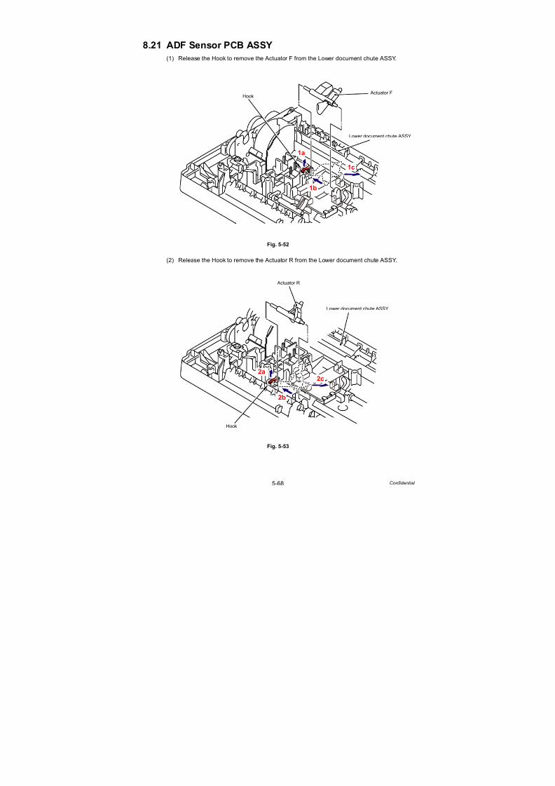
7/18/2019 Brother Mfc 9125cn 9325cw en 5694 Mfp Sm
http://slidepdf.com/reader/full/brother-mfc-9125cn-9325cw-en-5694-mfp-sm 295/597
5-68 Confidential
8.21 ADF Sensor PCB ASSY
(1) Release the Hook to remove the Actuator F from the Lower document chute ASSY.
Fig. 5-52
(2) Release the Hook to remove the Actuator R from the Lower document chute ASSY.
Fig. 5-53
Hook
Lower document chute ASSY
Actuator F
1a
1b
1c
Hook
Lower document chute ASSY
Actuator R
2a
2b
2c

7/18/2019 Brother Mfc 9125cn 9325cw en 5694 Mfp Sm
http://slidepdf.com/reader/full/brother-mfc-9125cn-9325cw-en-5694-mfp-sm 296/597
5-69 Confidential
(3) Release the two Hooks of the Lower document chute ASSY pressing the ADF sensor PCB
ASSY.
Fig. 5-54
(4) Turn the Shutter part of the Actuator ADF cover to the direction shown in the figure below
and remove it.
Fig. 5-55
Lower document chute ASSY
Hook
ADF sensor PCB ASSY
ADF sensor PCB ASSY
Lower document chute ASSY
Shutter part
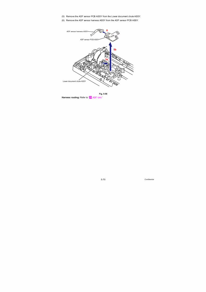
7/18/2019 Brother Mfc 9125cn 9325cw en 5694 Mfp Sm
http://slidepdf.com/reader/full/brother-mfc-9125cn-9325cw-en-5694-mfp-sm 297/597
5-70 Confidential
(5) Remove the ADF sensor PCB ASSY from the Lower document chute ASSY.
(6) Remove the ADF sensor harness ASSY from the ADF sensor PCB ASSY.
Fig. 5-56
Harness routing: Refer to “ ADF Unit.”
ADF sensor PCB ASSY
ADF sensor harness ASSY
5a
5b
Lower document chute ASSY
6

7/18/2019 Brother Mfc 9125cn 9325cw en 5694 Mfp Sm
http://slidepdf.com/reader/full/brother-mfc-9125cn-9325cw-en-5694-mfp-sm 298/597
5-71 Confidential
8.22 Drive Frame ASSY
(1) Remove the two Taptite cup B M3x10 screws from the Lower document chute ASSY.
Fig. 5-57
(2) Release the two Hooks to remove the Lower document chute ASSY from the Document
cover sub ASSY.
Fig. 5-58
Lower document
Taptite cup B M3x10
Taptite cup B M3x10
Document cover sub ASSY
chute ASSY
Hook
Document cover sub ASSY
Lower document chute ASSY
Hook
Rib
Rib
ADF motor
2a
2b
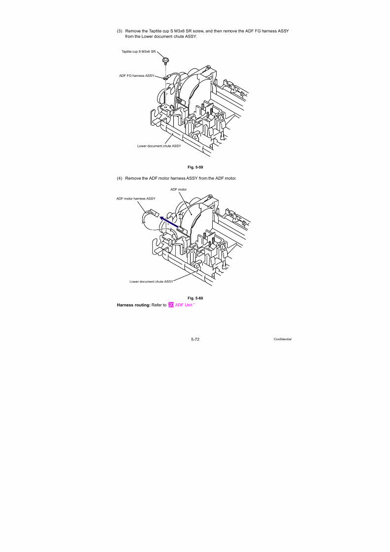
7/18/2019 Brother Mfc 9125cn 9325cw en 5694 Mfp Sm
http://slidepdf.com/reader/full/brother-mfc-9125cn-9325cw-en-5694-mfp-sm 299/597
5-72 Confidential
(3) Remove the Taptite cup S M3x6 SR screw, and then remove the ADF FG harness ASSY
from the Lower document chute ASSY.
Fig. 5-59
(4) Remove the ADF motor harness ASSY from the ADF motor.
Fig. 5-60
Harness routing: Refer to “ ADF Unit.”
Lower document chute ASSY
ADF FG harness ASSY
Taptite cup S M3x6 SR
ADF motor
ADF motor harness ASSY
Lower document chute ASSY

7/18/2019 Brother Mfc 9125cn 9325cw en 5694 Mfp Sm
http://slidepdf.com/reader/full/brother-mfc-9125cn-9325cw-en-5694-mfp-sm 300/597
5-73 Confidential
(5) Remove the two Taptite cup B M3x10 screws, and then remove the Drive frame ASSY
from the Lower document chute ASSY.
Fig. 5-61
(6) Remove the Taptite bind S M3x6 screw, and then remove the ADF motor from the
Drive frame ASSY.
Fig. 5-62
Taptite cup B M3x10
Lower document chute ASSY
Drive frame ASSY
Taptite cup B M3x10
Taptite bind S M3x6
Drive frame ASSY
ADF motor
Hook
6a
6b
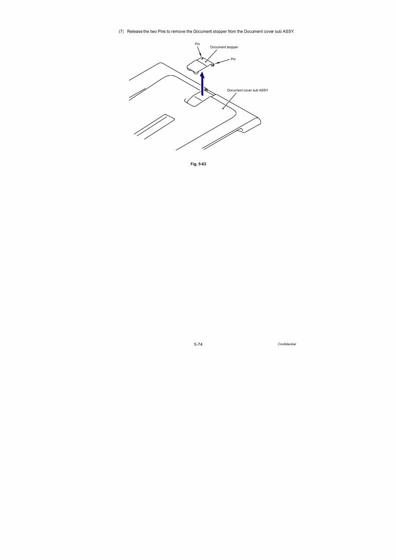
7/18/2019 Brother Mfc 9125cn 9325cw en 5694 Mfp Sm
http://slidepdf.com/reader/full/brother-mfc-9125cn-9325cw-en-5694-mfp-sm 301/597
5-74 Confidential
(7) Release the two Pins to remove the Document stopper from the Document cover sub ASSY.
Fig. 5-63
Pin
Document cover sub ASSY
Document stopper
Pin

7/18/2019 Brother Mfc 9125cn 9325cw en 5694 Mfp Sm
http://slidepdf.com/reader/full/brother-mfc-9125cn-9325cw-en-5694-mfp-sm 302/597
5-75 Confidential
8.23 Paper Stack Lever
(1) Push the both ends of the Paper stack lever on the left side inward to remove the Pins,
and remove the Paper stack lever from the Lower document chute ASSY.
(2) Remove the Paper stack lever on the right side in the same way.
Fig. 5-64
(3) Remove the Paper stack lever spring from the Paper stack lever.
Fig. 5-65
Paper stack lever
Lower document chute ASSY
Lower document chute ASSY
Pin
1a
1a
1a1a
1b
Paper stack lever
Paper stack lever spring

7/18/2019 Brother Mfc 9125cn 9325cw en 5694 Mfp Sm
http://slidepdf.com/reader/full/brother-mfc-9125cn-9325cw-en-5694-mfp-sm 303/597
5-76 Confidential
8.24 Document Hold ASSY
(1) Turn the Lower document chute ASSY upside down.
(2) Release the two Pins to remove the Document hold ASSY and Document hold spring
from the Lower document chute ASSY.
Fig. 5-66
Lower document chute ASSY
Pin
Document hold ASSY
Document hold spring
Hook
Hook
Pin
2a
2a
2c2d
2b

7/18/2019 Brother Mfc 9125cn 9325cw en 5694 Mfp Sm
http://slidepdf.com/reader/full/brother-mfc-9125cn-9325cw-en-5694-mfp-sm 304/597
5-77 Confidential
8.25 Control Panel Cover ASSY
(1) Release the eight Hooks to remove the Control panel cover ASSY from the Document
scanner unit.
Fig. 5-67
Hook
Document scanner unit
Hook
Hook
Hook
Control panel cover ASSY

7/18/2019 Brother Mfc 9125cn 9325cw en 5694 Mfp Sm
http://slidepdf.com/reader/full/brother-mfc-9125cn-9325cw-en-5694-mfp-sm 305/597
5-78 Confidential
8.26 Document Scanner Unit
(1) Remove the four Taptite cup B M3x10 screws (2 each at upper and lower sides) of the
Panel unit, and then lift the Panel unit.
Fig. 5-68
(2) Gently lift up the Panel unit slightly from the Document scanner unit and disconnect theConnector (CN1) from the Panel PCB ASSY.
Fig. 5-69
Harness routing: Refer to “ Panel Unit.”
Note:
Do not pull the Panel unit strongly because a Harness is connected.
Taptite cup B M3x10
Panel unit
Taptite cup B M3x10
Document scanner unit
Panel unit
Panel PCB ASSY
CN1
Document scanner unit
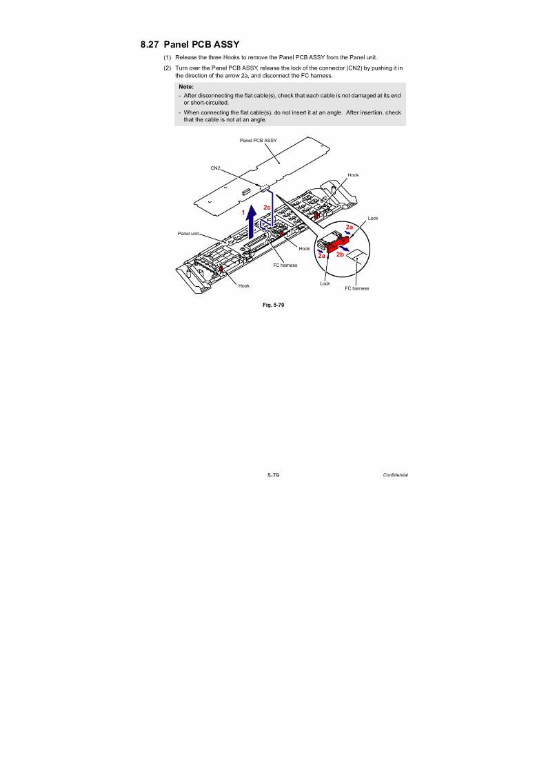
7/18/2019 Brother Mfc 9125cn 9325cw en 5694 Mfp Sm
http://slidepdf.com/reader/full/brother-mfc-9125cn-9325cw-en-5694-mfp-sm 306/597
5-79 Confidential
8.27 Panel PCB ASSY
(1) Release the three Hooks to remove the Panel PCB ASSY from the Panel unit.
(2) Turn over the Panel PCB ASSY, release the lock of the connector (CN2) by pushing it in
the direction of the arrow 2a, and disconnect the FC harness.
Fig. 5-70
Note:- After disconnecting the flat cable(s), check that each cable is not damaged at its end
or short-circuited.
- When connecting the flat cable(s), do not insert it at an angle. After insertion, check
that the cable is not at an angle.
Hook
Panel unit
Panel PCB ASSY
Hook
Hook
CN2
Lock
FC harnessLock
FC harness
2b
12c
2a
2a

7/18/2019 Brother Mfc 9125cn 9325cw en 5694 Mfp Sm
http://slidepdf.com/reader/full/brother-mfc-9125cn-9325cw-en-5694-mfp-sm 307/597
5-80 Confidential
8.28 Rubber Key L/R
(1) Remove the Rubber key R and Printed rubber key L from the Panel unit.
Fig. 5-71
Panel unit
Rubber key R
Printed rubber key L
Boss
Boss
Boss
Boss

7/18/2019 Brother Mfc 9125cn 9325cw en 5694 Mfp Sm
http://slidepdf.com/reader/full/brother-mfc-9125cn-9325cw-en-5694-mfp-sm 308/597
5-81 Confidential
8.29 LCD/LCD Cover
(1) Remove the Panel light guide from the Panel cover generic.
Fig. 5-72
(2) Release the four Hooks to remove the LCD cover from the Panel cover generic.
Fig. 5-73
Panel light guide
Panel cover generic
Hook
Panel cover generic
LCD cover
HookHook
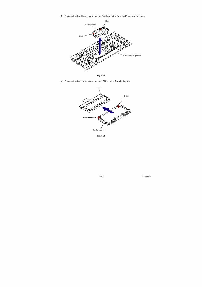
7/18/2019 Brother Mfc 9125cn 9325cw en 5694 Mfp Sm
http://slidepdf.com/reader/full/brother-mfc-9125cn-9325cw-en-5694-mfp-sm 309/597
5-82 Confidential
(3) Release the two Hooks to remove the Backlight guide from the Panel cover generic.
Fig. 5-74
(4) Release the two Hooks to remove the LCD from the Backlight guide.
Fig. 5-75
Hook
Panel cover generic
Hook
Backlight guide
Hook
Backlight guide
LCD
Hook

7/18/2019 Brother Mfc 9125cn 9325cw en 5694 Mfp Sm
http://slidepdf.com/reader/full/brother-mfc-9125cn-9325cw-en-5694-mfp-sm 310/597
5-83 Confidential
8.30 NCU PCB ASSY (NCU model only)
(1) Remove the two Taptite pan (washer) B M4x12 DA screws, and then remove NCU FG
harness ASSY 2 from the NCU shield.
(2) Remove the Screw PAN (S/P washer) M3.5x6 screw, and then remove the NCU FG
harness ASSY 1 from the NCU shield.
(3) Lift the NCU shield from the Joint cover sub ASSY.
Fig. 5-76
(4) Turn the NCU shield upside down.
(5) Remove the two Taptite cup S M3x6 SR screws, and then remove the NCU PCB ASSY from the NCU shield.
(6) Disconnect the NCU harness ASSY from the NCU PCB ASSY.
Fig. 5-77
Harness routing: Refer to “ NCU Shield.”
NCU shield
Taptite pan (washer) B M4x12 DA
Screw PAN (S/P washer) M3.5x6
NCU FG harness ASSY 1
Joint cover sub ASSY
NCU FG harness ASSY 2
Taptite cup S M3x6 SR
NCU shield
NCU PCB ASSY
NCU harness ASSY
6
5
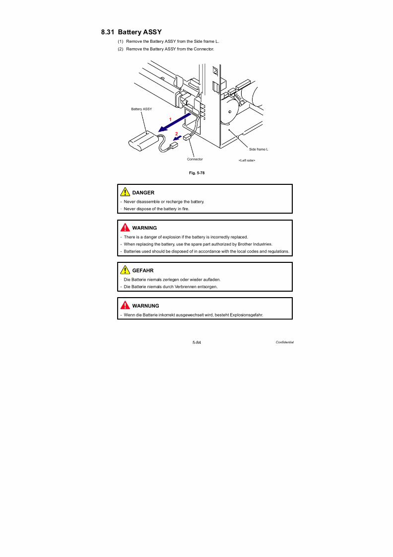
7/18/2019 Brother Mfc 9125cn 9325cw en 5694 Mfp Sm
http://slidepdf.com/reader/full/brother-mfc-9125cn-9325cw-en-5694-mfp-sm 311/597
5-84 Confidential
8.31 Battery ASSY
(1) Remove the Battery ASSY from the Side frame L.
(2) Remove the Battery ASSY from the Connector.
Fig. 5-78
DANGER
- Never disassemble or recharge the battery.
- Never dispose of the battery in fire.
WARNING
- There is a danger of explosion if the battery is incorrectly replaced.
- When replacing the battery, use the spare part authorized by Brother Industries.
- Batteries used should be disposed of in accordance with the local codes and regulations.
GEFAHR
- Die Batterie niemals zerlegen oder wieder aufladen.
- Die Batterie niemals durch Verbrennen entsorgen.
WARNUNG
- Wenn die Batterie inkorrekt ausgewechselt wird, besteht Explosionsgefahr.
Side frame L
Battery ASSY
Connector
2
1
<Left side>

7/18/2019 Brother Mfc 9125cn 9325cw en 5694 Mfp Sm
http://slidepdf.com/reader/full/brother-mfc-9125cn-9325cw-en-5694-mfp-sm 312/597
5-85 Confidential
8.32 Pull Arm Guide
(1) Remove the Lock claw and remove the left Pull arm guide from the Joint cover sub ASSY.
(2) Remove the right Pull arm guide in the same way.
Fig. 5-79
Lock claw
Joint cover sub ASSY
Pull arm guide
Hook

7/18/2019 Brother Mfc 9125cn 9325cw en 5694 Mfp Sm
http://slidepdf.com/reader/full/brother-mfc-9125cn-9325cw-en-5694-mfp-sm 313/597
5-86 Confidential
8.33 Top Dress Cover L/R
(1) Remove the Taptite bind B M4x12 screw from the Top dress cover L.
(2) Open the Joint cover sub ASSY and remove the two Taptite cup B M3x8 screws from the
Top dress cover L.
(3) Release the Hook to remove the Top dress cover L.
(4) Remove the Top dress cover R in the same way.
Fig. 5-80
Top dress cover L
Taptite bind B M4x12
Joint cover sub ASSY
Taptite cup B M3x8
Hook

7/18/2019 Brother Mfc 9125cn 9325cw en 5694 Mfp Sm
http://slidepdf.com/reader/full/brother-mfc-9125cn-9325cw-en-5694-mfp-sm 314/597
5-87 Confidential
8.34 FB Lock Lever L/R
(1) Remove the FB lock spring from the spring hook and FB lock lever L of the joint cover sub
ASSY.
Fig. 5-81
(2) Remove the Taptite bind B M4x12 screw from the Blind cover L.
(3) Release the Hook to remove the Blind cover L from the Joint cover sub ASSY.
Fig. 5-82
FB lock lever L
Joint cover sub ASSY
Spring hook
FB lock spring
Joint cover sub ASSY
Hook
Taptite bind B M4x12
Blind cover L

7/18/2019 Brother Mfc 9125cn 9325cw en 5694 Mfp Sm
http://slidepdf.com/reader/full/brother-mfc-9125cn-9325cw-en-5694-mfp-sm 315/597
5-88 Confidential
(4) Remove the FB lock lever L from the Joint cover sub ASSY.
Fig. 5-83
(5) Remove the FB lock spring from the spring hook and FB lock lever R of the joint cover sub
ASSY.
Fig. 5-84
Joint cover sub ASSY
FB lock lever L
FB lock lever R
FB lock spring
Spring hook
Joint cover sub ASSY

7/18/2019 Brother Mfc 9125cn 9325cw en 5694 Mfp Sm
http://slidepdf.com/reader/full/brother-mfc-9125cn-9325cw-en-5694-mfp-sm 316/597
5-89 Confidential
(6) Remove the Taptite bind B M4x12 screw from the Blind cover R.
(7) Release the Hook to remove the Blind cover R from the Joint cover sub ASSY.
Fig. 5-85
(8) Remove the FB lock lever R from the Joint cover sub ASSY.
Fig. 5-86
Joint cover sub ASSY
Hook
Taptite bind B M4x12Blind cover R
Joint cover sub ASSY
FB lock lever R

7/18/2019 Brother Mfc 9125cn 9325cw en 5694 Mfp Sm
http://slidepdf.com/reader/full/brother-mfc-9125cn-9325cw-en-5694-mfp-sm 317/597
5-90 Confidential
8.35 Joint Cover Lock Spring/Joint Cover Lock Lever
(1) Remove the “A” of Joint cover lock spring from the “B” of the left side of Joint cover lock
lever, and remove the “C” of the Joint cover lock spring from the “D” of the Joint cover lock
lever.
Fig. 5-87
(2) Release the two Pins of the left side of Joint cover lock lever, and remove the Joint cover
lock lever and Joint cover lock spring from the Joint cover sub ASSY.
(3) Remove the Joint cover lock lever and Joint cover lock spring on the right side in the
same way.
Fig. 5-88
Joint cover sub ASSY
Joint cover lock lever
Joint cover lock spring
“A”
“B” “D”
“C”
1a
1b
Joint cover sub ASSY
Joint cover lock lever
Joint cover lock spring
Pin
“D”
Pin

7/18/2019 Brother Mfc 9125cn 9325cw en 5694 Mfp Sm
http://slidepdf.com/reader/full/brother-mfc-9125cn-9325cw-en-5694-mfp-sm 318/597
5-91 Confidential
8.36 Wireless LAN PCB ASSY (Wireless LAN model only)
(1) Disconnect the three Connectors (CN1, CN2, CN13) and cables from the Main PCB ASSY.
Fig. 5-89
(2) Remove the two Taptite bind B M4x12 screws, and then release the seven Hooks to
remove the Front cover top ASSY from the Main body.
Fig. 5-90
CN24 CN20
CN27
CN26
CN23 CN22 CN19 CN15 CN10
CN1
CN2
CN3
CN18
CN17
CN16 CN14 CN13 CN11 CN8
CN5
CN6
Main PCB ASSY
Taptite bind B M4x12
Front cover top ASSY
Main body
2a
2b
Hook
Hook
Hook

7/18/2019 Brother Mfc 9125cn 9325cw en 5694 Mfp Sm
http://slidepdf.com/reader/full/brother-mfc-9125cn-9325cw-en-5694-mfp-sm 319/597
5-92 Confidential
(3) Release the all harnesses in the USB holder.
(4) Release the Hook and hold up the Wireless LAN PCB ASSY slightly in the direction of the
arrow 4.
(5) Turn over the Panel harness protective sheet in the direction of the arrow 5.
(6) Remove the Wireless LAN PCB ASSY from the Front cover top ASSY.
Fig. 5-91
(7) Remove the Panel harness protective sheet from the Front cover top ASSY.
Fig. 5-92
Wireless LAN PCB ASSY
Hook
4
6
Panel harness
5protective sheet
Front cover top ASSY
Panel harness protective sheet
Front cover top ASSY

7/18/2019 Brother Mfc 9125cn 9325cw en 5694 Mfp Sm
http://slidepdf.com/reader/full/brother-mfc-9125cn-9325cw-en-5694-mfp-sm 320/597
5-93 Confidential
(8) Disconnect the Connector of the WLAN-MAIN harness ASSY from the Wireless LAN PCB
ASSY.
Fig. 5-93
Harness routing: Refer to “ Front Cover Top ASSY (Wireless LAN PCB ASSY, Speaker
Unit).”
Wireless LAN PCB ASSY
WLAN-MAIN harness ASSY

7/18/2019 Brother Mfc 9125cn 9325cw en 5694 Mfp Sm
http://slidepdf.com/reader/full/brother-mfc-9125cn-9325cw-en-5694-mfp-sm 321/597
5-94 Confidential
8.37 USB Direct Interface Relay PCB ASSY
(USB direct interface model only)
(1) Remove the two Taptite bind B M3x8 screws and FG harness.
(2) Remove the USB direct interface relay PCB ASSY from the Front cover top ASSY.
Fig. 5-94
(3) Disconnect the Connector of the USB A-MAIN relay harness ASSY from the USB direct
interface relay PCB ASSY.
Fig. 5-95
Harness routing: Refer to “ Front Cover Top ASSY (USB Direct Interface Relay PCB
ASSY).”
Taptite bind B M3x8
Front cover top ASSY
FG harness
USB direct interface relay PCB ASSY
USB A-MAIN relay harness ASSY
USB direct interface relay PCB ASSY
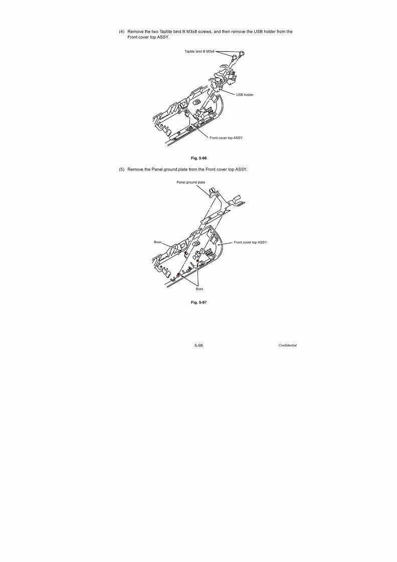
7/18/2019 Brother Mfc 9125cn 9325cw en 5694 Mfp Sm
http://slidepdf.com/reader/full/brother-mfc-9125cn-9325cw-en-5694-mfp-sm 322/597
5-95 Confidential
(4) Remove the two Taptite bind B M3x8 screws, and then remove the USB holder from the
Front cover top ASSY.
Fig. 5-96
(5) Remove the Panel ground plate from the Front cover top ASSY.
Fig. 5-97
Taptite bind B M3x8
USB holder
Front cover top ASSY
Panel ground plate
Front cover top ASSY
Boss
Boss

7/18/2019 Brother Mfc 9125cn 9325cw en 5694 Mfp Sm
http://slidepdf.com/reader/full/brother-mfc-9125cn-9325cw-en-5694-mfp-sm 323/597
5-96 Confidential
8.38 Panel Ground Plate 2
(Only the models without the USB direct interface)
(1) Remove the two Taptite bind B M3x8 screws and FG harness.
(2) Remove the Panel ground plate 2 from the Front cover top ASSY.
Fig. 5-98
(3) Remove the two Taptite bind B M3x8 screws, and then remove the USB holder from the
Front cover top ASSY.
Fig. 5-99
Taptite bind B M3x8
Front cover top ASSY
FG harness
Panel ground plate 2
Taptite bind B M3x8
USB holder
Front cover top ASSY

7/18/2019 Brother Mfc 9125cn 9325cw en 5694 Mfp Sm
http://slidepdf.com/reader/full/brother-mfc-9125cn-9325cw-en-5694-mfp-sm 324/597
5-97 Confidential
(4) Remove the Panel ground plate from the Front cover top ASSY.
Fig. 5-100
Panel ground plate
Front cover top ASSY
Boss
Boss

7/18/2019 Brother Mfc 9125cn 9325cw en 5694 Mfp Sm
http://slidepdf.com/reader/full/brother-mfc-9125cn-9325cw-en-5694-mfp-sm 325/597
5-98 Confidential
8.39 Speaker Unit/Front Cover Top Base
(1) Release the Hook by pushing the “A” and remove the Speaker spring from the Front cover
top base by sliding it in the direction of the arrow.
Fig. 5-101
(2) Remove the Speaker unit and Speaker spacer from the Front cover top base.
Fig. 5-102
Harness routing: Refer to “ Front Cover Top ASSY (Wireless LAN PCB ASSY, SpeakerUnit).”
“A”
Hook
Front cover top base
Speaker spring
Speaker unit
Front cover top base
Speaker unit
Speaker spacer

7/18/2019 Brother Mfc 9125cn 9325cw en 5694 Mfp Sm
http://slidepdf.com/reader/full/brother-mfc-9125cn-9325cw-en-5694-mfp-sm 326/597
5-99 Confidential
8.40 Front Cover
(1) Disconnect the Connector (CN6) from the Main PCB ASSY.
Fig. 5-103
(2) Disconnect the Connector (CN13) and cables from the Engine PCB ASSY.
Fig. 5-104
CN24 CN20
CN27
CN26
CN23 CN22 CN19 CN15 CN10
CN1
CN2
CN3
CN18
CN17
CN16 CN14 CN13 CN11 CN8
CN5
CN6
Main PCB ASSY
CN11
CN15CN14CN13
CN1
CN2
CN3
CN10
CN9
CN8 CN7 CN6 CN5CN4
Engine PCB ASSY

7/18/2019 Brother Mfc 9125cn 9325cw en 5694 Mfp Sm
http://slidepdf.com/reader/full/brother-mfc-9125cn-9325cw-en-5694-mfp-sm 327/597
5-100 Confidential
(3) Remove the two Taptite bind B M4x12 screws from the Front cover.
(4) Release the six Hooks and two Bosses to remove the Front cover from the Main body.
(5) Remove the two FG plate from the Front cover.
Fig. 5-105
Boss
Boss
Main body
Front cover
Taptite bind B M4x12
Taptite bind B M4x12
Hook
<Front>
FG plate
FG plate
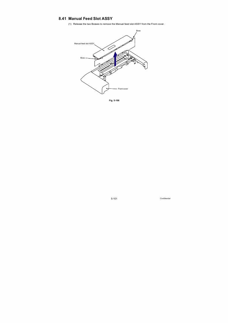
7/18/2019 Brother Mfc 9125cn 9325cw en 5694 Mfp Sm
http://slidepdf.com/reader/full/brother-mfc-9125cn-9325cw-en-5694-mfp-sm 328/597
5-101 Confidential
8.41 Manual Feed Slot ASSY
(1) Release the two Bosses to remove the Manual feed slot ASSY from the Front cover.
Fig. 5-106
Boss
Boss
Front cover
Manual feed slot ASSY

7/18/2019 Brother Mfc 9125cn 9325cw en 5694 Mfp Sm
http://slidepdf.com/reader/full/brother-mfc-9125cn-9325cw-en-5694-mfp-sm 329/597
5-102 Confidential
8.42 TC Arm Spring
(1) Disconnect the FFC harness:MAIN-LED CTL (CN24) from the Main PCB ASSY.
Fig. 5-107
(2) Release the Hook to remove the LED power relay PCB ASSY from the Side frame L.
Fig. 5-108
Note:
- After disconnecting the flat cable(s), check that each cable is not damaged at its end
or short-circuited.- When connecting the flat cable(s), do not insert it at an angle. After insertion, check
that the cable is not at an angle.
CN24 CN20
CN27
CN26
CN23 CN22 CN19 CN15 CN10
CN1
CN2
CN3
CN18
CN17
CN16 CN14 CN13 CN11 CN8
CN5
CN6
Main PCB ASSY
Hook
<Left side>
LED power relay PCB
Side frame L
Top cover unit
ASSY

7/18/2019 Brother Mfc 9125cn 9325cw en 5694 Mfp Sm
http://slidepdf.com/reader/full/brother-mfc-9125cn-9325cw-en-5694-mfp-sm 330/597
5-103 Confidential
(3) Disconnect the Connector from the LED power relay PCB ASSY.
Fig. 5-109
(4) Remove the Taptite cup S M3x6 SR screw, and then remove the LED FG harness from
the Main PCB shield plate.
Fig. 5-110
Note:
- After disconnecting the flat cable(s), check that each cable is not damaged at its end
or short-circuited.
- When connecting the flat cable(s), do not insert it at an angle. After insertion, check
that the cable is not at an angle.
LED power relay PCB ASSY
Connector
LED FG harness
Main PCB(Taptite cup S M3x6 SR)
Main PCB shield plate

7/18/2019 Brother Mfc 9125cn 9325cw en 5694 Mfp Sm
http://slidepdf.com/reader/full/brother-mfc-9125cn-9325cw-en-5694-mfp-sm 331/597
5-104 Confidential
(5) Remove the Relay-LED harness ASSY and FFC harness: MAIN-LED CTL of the Joint
cover sub ASSY from the Side frame L.
Fig. 5-111
(6) Remove the TC arm spring from the Top cover arm L.
Fig. 5-112
Side frame L
Relay-LED harness ASSY
FFC harness:MAIN-LED CTL
LED FG harness ASSY
Joint cover sub ASSY
Top cover arm L
TC arm spring
<Left side>
Hook
Joint cover sub ASSY
Hook

7/18/2019 Brother Mfc 9125cn 9325cw en 5694 Mfp Sm
http://slidepdf.com/reader/full/brother-mfc-9125cn-9325cw-en-5694-mfp-sm 332/597
5-105 Confidential
(7) Remove the TC arm spring from the Top cover arm R.
Fig. 5-113
Fig. 5-114
Assembling Note:
The assembling direction of the TC arm spring is fixed.
Make sure to assemble the TC arm spring in the direction shown in the figure below.
- Make sure to assemble the TC arm spring in a way that the end of the spring hook on the
joint cover sub ASSY side comes to the bottom.
- Make sure to assemble the spring hook of the TC arm spring in a way that the end with a
fold comes to the top cover arm side and the end without a fold comes to the joint cover
sub ASSY side.
Top cover arm R
TC arm spring
<Right side>
Hook
Hook
Joint cover sub ASSY
TC arm spring
End of the spring hook
Joint cover sub ASSY side Top cover arm side
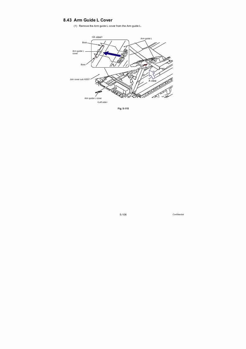
7/18/2019 Brother Mfc 9125cn 9325cw en 5694 Mfp Sm
http://slidepdf.com/reader/full/brother-mfc-9125cn-9325cw-en-5694-mfp-sm 333/597
5-106 Confidential
8.43 Arm Guide L Cover
(1) Remove the Arm guide L cover from the Arm guide L.
Fig. 5-115
Arm guide L
Arm guide L cover
Boss
Boss
Arm guide L
<Left side>
<A view>
A view
cover
Join cover sub ASSY

7/18/2019 Brother Mfc 9125cn 9325cw en 5694 Mfp Sm
http://slidepdf.com/reader/full/brother-mfc-9125cn-9325cw-en-5694-mfp-sm 334/597
5-107 Confidential
8.44 Joint Cover Sub ASSY
(1) Remove the Pin of the Top cover arm L from the “A” of the Arm guide L.
Fig. 5-116
(2) Remove the Pin of the Top cover arm R from the “B” of the Arm guide R.
Fig. 5-117
Arm guide L
"A"
Top cover arm L
Pin
Top cover arm L
Arm guide L
<Left side>
Joint cover sub ASSY
1b
1a1a
Arm guide R "B"
Top cover arm R
Pin
Joint cover sub ASSY
Arm guide R
Top cover arm R
<Right side>
2a
2b
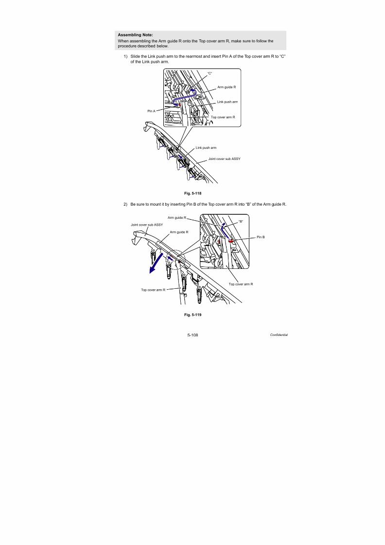
7/18/2019 Brother Mfc 9125cn 9325cw en 5694 Mfp Sm
http://slidepdf.com/reader/full/brother-mfc-9125cn-9325cw-en-5694-mfp-sm 335/597
5-108 Confidential
1) Slide the Link push arm to the rearmost and insert Pin A of the Top cover arm R to “C”
of the Link push arm.
Fig. 5-118
2) Be sure to mount it by inserting Pin B of the Top cover arm R into “B” of the Arm guide R.
Fig. 5-119
Assembling Note:
When assembling the Arm guide R onto the Top cover arm R, make sure to follow the
procedure described below.
Link push arm
Joint cover sub ASSY
“C“
Link push arm
Pin A
Arm guide R
Top cover arm R
“B“Joint cover sub ASSY
Top cover arm R
Arm guide R
Arm guide R
Top cover arm R
Pin B
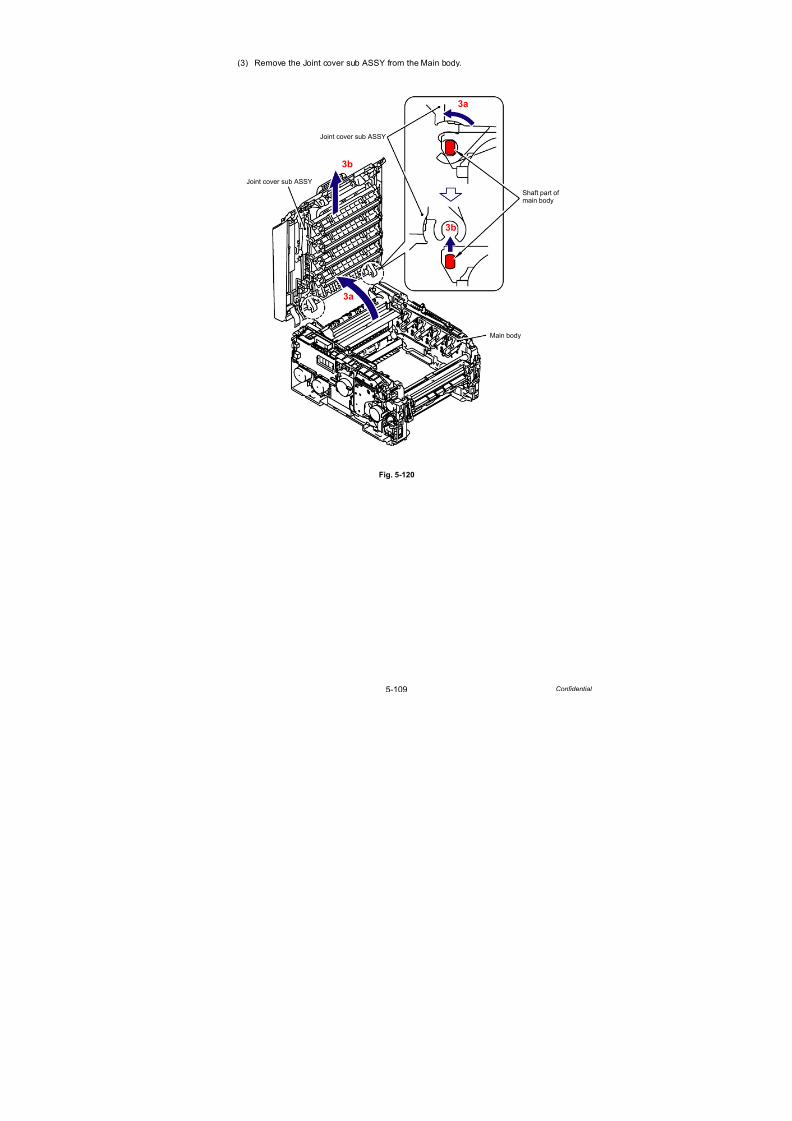
7/18/2019 Brother Mfc 9125cn 9325cw en 5694 Mfp Sm
http://slidepdf.com/reader/full/brother-mfc-9125cn-9325cw-en-5694-mfp-sm 336/597
5-109 Confidential
(3) Remove the Joint cover sub ASSY from the Main body.
Fig. 5-120
Main body
3a
3b
3a
Joint cover sub ASSY
Joint cover sub ASSY
Shaft part ofmain body
3b

7/18/2019 Brother Mfc 9125cn 9325cw en 5694 Mfp Sm
http://slidepdf.com/reader/full/brother-mfc-9125cn-9325cw-en-5694-mfp-sm 337/597
5-110 Confidential
8.45 Inner Chute ASSY 2
(1) Remove the two Taptite bind B M4x12 screws from the Inner chute ASSY 2.
(2) Release the two Bosses to remove the Inner chute ASSY 2 from the Joint cover sub ASSY.
Fig. 5-121
Fig. 5-122
Assembling Note:When assembling the Inner chute ASSY 2, make sure to assemble it in a way that the two
“A” of the Joint cover sub ASSY come above the Inner chute ASSY 2.
BossJoint cover sub ASSY
Inner chute ASSY 2
Boss
Taptite bind B M4x12
Joint cover sub ASSY
Inner chute ASSY 2
"A"

7/18/2019 Brother Mfc 9125cn 9325cw en 5694 Mfp Sm
http://slidepdf.com/reader/full/brother-mfc-9125cn-9325cw-en-5694-mfp-sm 338/597
5-111 Confidential
8.46 TC Release Lever
(1) Remove the two Taptite bind B M4x12 screws, and then remove the Arm guide L from the
Joint cover sub ASSY.
Fig. 5-123
(2) Remove the two Taptite bind B M4x12 screws, and then remove the TC harness cover 2
from the Joint cover sub ASSY.
Fig. 5-124
Taptite bind B M4x12
Joint cover sub ASSY
Arm guide L
Joint cover sub ASSY
Taptite bind B M4x12
TC harness cover 2

7/18/2019 Brother Mfc 9125cn 9325cw en 5694 Mfp Sm
http://slidepdf.com/reader/full/brother-mfc-9125cn-9325cw-en-5694-mfp-sm 339/597
5-112 Confidential
(3) Tilt the TC harness cover 1 in the direction of the arrow 3a, remove the three Hooks, and
remove the TC harness cover 1 from the Joint cover sub ASSY.
Fig. 5-125
(4) Remove the two Taptite bind B M4x12 screws, and then remove the Arm guide R from the
Joint cover sub ASSY.
Fig. 5-126
Joint cover sub ASSY
TC harness cover 1
Hook
Hook
Hook
Hook
TC harness cover 1 Hook
TC harness cover 1
3b
3a3a 3b
Taptite bind B M4x12
Joint cover sub ASSY
Arm guide R
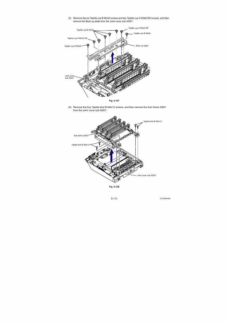
7/18/2019 Brother Mfc 9125cn 9325cw en 5694 Mfp Sm
http://slidepdf.com/reader/full/brother-mfc-9125cn-9325cw-en-5694-mfp-sm 340/597
5-113 Confidential
(5) Remove the six Taptite cup B M3x8 screws and two Taptite cup S M3x6 SR screws, and then
remove the Back up plate from the Joint cover sub ASSY.
Fig. 5-127
(6) Remove the four Taptite bind B M4x12 screws, and then remove the Sub frame ASSY
from the Joint cover sub ASSY.
Fig. 5-128
Taptite cup B M3x8
Taptite cup S M3x6 SR
Joint cover
Back up plate
Taptite cup S M3x6 SR
Taptite cup B M3x8
Taptite cup B M3x8
sub ASSY
Taptite bind B M4x12
Joint cover sub ASSY
Sub frame ASSY
Taptite bind B M4x12
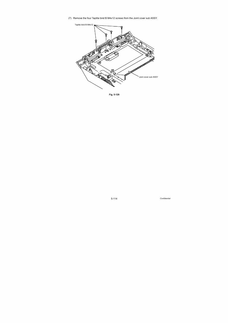
7/18/2019 Brother Mfc 9125cn 9325cw en 5694 Mfp Sm
http://slidepdf.com/reader/full/brother-mfc-9125cn-9325cw-en-5694-mfp-sm 341/597
5-114 Confidential
(7) Remove the four Taptite bind B M4x12 screws from the Joint cover sub ASSY.
Fig. 5-129
Joint cover sub ASSY
Taptite bind B M4x12

7/18/2019 Brother Mfc 9125cn 9325cw en 5694 Mfp Sm
http://slidepdf.com/reader/full/brother-mfc-9125cn-9325cw-en-5694-mfp-sm 342/597
5-115 Confidential
(8) Remove the Taptite bind B M4x12 screw, and then release the nine Hooks to remove the
Inner chute ASSY 1 from the Joint cover sub ASSY.
Fig. 5-130
Note:
When you remove any of the following parts, be careful not to damage the Paper stopper.
Joint cover sub ASSY
Inner chute ASSY 1
Paper stopper
Taptite bind B M4x12
HookJoint cover sub ASSY
Inner chute ASSY 1
Hook
Hook
Hook
Hook
Hook
Hook
Hook
Inner chute ASSY 1
Hook
8b
8a8a

7/18/2019 Brother Mfc 9125cn 9325cw en 5694 Mfp Sm
http://slidepdf.com/reader/full/brother-mfc-9125cn-9325cw-en-5694-mfp-sm 343/597
5-116 Confidential
(9) Release the Hook to remove the TC release lever shaft from the Inner chute ASSY 1.
Fig. 5-131
(10) Remove the Inner TC release lever from the chute ASSY 1.
Fig. 5-132
Hook
Inner chute ASSY 1
TC release lever shaft
TC release lever shaft
TC release lever
9b
9a9b
Inner chute ASSY 1
TC release lever

7/18/2019 Brother Mfc 9125cn 9325cw en 5694 Mfp Sm
http://slidepdf.com/reader/full/brother-mfc-9125cn-9325cw-en-5694-mfp-sm 344/597
5-117 Confidential
8.47 Paper Stack Lever ASSY
(1) Release the Pin to remove the Paper stack lever ASSY on the left side from the Inner
chute ASSY 1.
(2) Remove the Paper stack lever ASSY on the right side in the same way.
Fig. 5-133
Inner chute ASSY 1
Paper stack lever ASSY
Paper stack lever ASSY
Pin
Pin
Pin
Pin

7/18/2019 Brother Mfc 9125cn 9325cw en 5694 Mfp Sm
http://slidepdf.com/reader/full/brother-mfc-9125cn-9325cw-en-5694-mfp-sm 345/597
5-118 Confidential
8.48 FFC Harness:MAIN-LED CTL
(1) Insert the two “A” of the removed Sub frame ASSY into the two “B” of the Main body and
close it as shown in the figure below.
Fig. 5-134
Sub frame ASSY
“A”
“A”
Main body
“B”
“B”
1a
1b

7/18/2019 Brother Mfc 9125cn 9325cw en 5694 Mfp Sm
http://slidepdf.com/reader/full/brother-mfc-9125cn-9325cw-en-5694-mfp-sm 346/597
5-119 Confidential
(2) Remove the four Taptite cup S M3x6 SR screws, and then remove the LED PCB cover
and Insulation sheet B from the Sub frame ASSY.
Fig. 5-135
(3) Disconnect the FFC harness:MAIN-LED CTL (CN5) from the LED head control PCB ASSY.
Fig. 5-136
Note:
- After disconnecting the flat cable(s), check that each cable is not damaged at its endor short-circuited.
- When connecting the flat cable(s), do not insert it at an angle. After insertion, check
that the cable is not at an angle.
Taptite cup S M3x6 SR
Sub frame ASSY
LED PCB cover
Taptite cup S M3x6 SR
Insulation sheet B
LED head control PCB ASSY
FFC harness:MAIN-LED CTL
CN5
FFC harness:MAIN-LED CTL
Lock
Lock
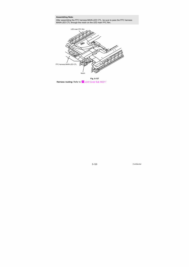
7/18/2019 Brother Mfc 9125cn 9325cw en 5694 Mfp Sm
http://slidepdf.com/reader/full/brother-mfc-9125cn-9325cw-en-5694-mfp-sm 347/597
5-120 Confidential
Fig. 5-137
Harness routing: Refer to “ Joint Cover Sub ASSY.”
Assembling Note:
After assembling the FFC harness:MAIN-LED CTL, be sure to pass the FFC harness:
MAIN-LED CTL through the notch on the LED main FFC film.
LED main FFC film
Notch
FFC harness:MAIN-LED CTL

7/18/2019 Brother Mfc 9125cn 9325cw en 5694 Mfp Sm
http://slidepdf.com/reader/full/brother-mfc-9125cn-9325cw-en-5694-mfp-sm 348/597
5-121 Confidential
8.49 LED Power Relay PCB ASSY
(1) Disconnect the Connector (CN6) of the LED power relay PCB ASSY from the LED head
control PCB ASSY.
Fig. 5-138
LED head control PCB ASSY
CN6
LED power relay PCB ASSY
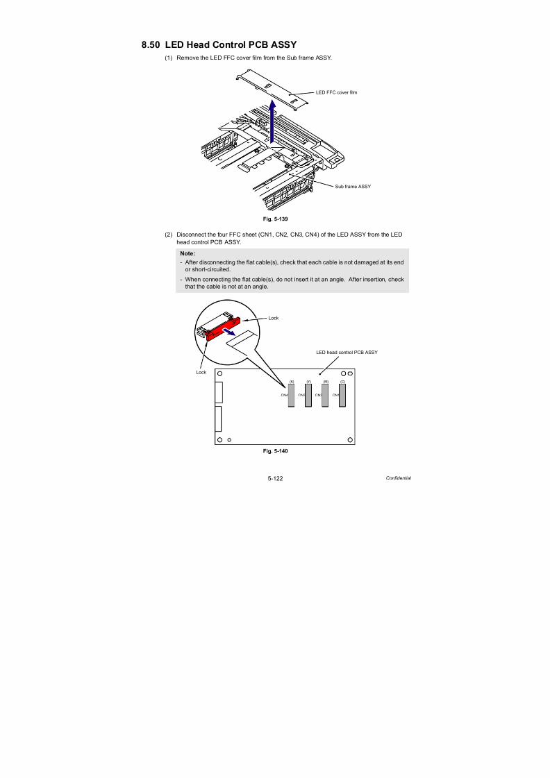
7/18/2019 Brother Mfc 9125cn 9325cw en 5694 Mfp Sm
http://slidepdf.com/reader/full/brother-mfc-9125cn-9325cw-en-5694-mfp-sm 349/597
5-122 Confidential
8.50 LED Head Control PCB ASSY
(1) Remove the LED FFC cover film from the Sub frame ASSY.
Fig. 5-139
(2) Disconnect the four FFC sheet (CN1, CN2, CN3, CN4) of the LED ASSY from the LED
head control PCB ASSY.
Fig. 5-140
Note:
- After disconnecting the flat cable(s), check that each cable is not damaged at its endor short-circuited.
- When connecting the flat cable(s), do not insert it at an angle. After insertion, check
that the cable is not at an angle.
Sub frame ASSY
LED FFC cover film
CN1CN2CN3CN4
(K) (Y) (M) (C)
LED head control PCB ASSY
Lock
Lock

7/18/2019 Brother Mfc 9125cn 9325cw en 5694 Mfp Sm
http://slidepdf.com/reader/full/brother-mfc-9125cn-9325cw-en-5694-mfp-sm 350/597
5-123 Confidential
(3) Remove the four Taptite cup S M3x6 SR screws, and then remove the LED head control
PCB ASSY from the Sub frame ASSY.
Fig. 5-141
Taptite cup S M3x6 SR
Taptite cup S M3x6 SR
LED head control PCB ASSY
Sub frame ASSY

7/18/2019 Brother Mfc 9125cn 9325cw en 5694 Mfp Sm
http://slidepdf.com/reader/full/brother-mfc-9125cn-9325cw-en-5694-mfp-sm 351/597
5-124 Confidential
8.51 LED ASSY/Holder Hook
(1) Remove the four FFC sheet from the Sub frame ASSY, and remove the Cores from each
of the FFC sheet.
Fig. 5-142
(2) Remove the Sub frame ASSY from the Main body, and place it with the LED ASSY side up.
Fig. 5-143
Sub frame ASSY
FFC sheet
FFC sheetCore
Main body
Sub frame ASSY
2a
2b
LED ASSY

7/18/2019 Brother Mfc 9125cn 9325cw en 5694 Mfp Sm
http://slidepdf.com/reader/full/brother-mfc-9125cn-9325cw-en-5694-mfp-sm 352/597
5-125 Confidential
(3) Release the Hook of the Holder hook at the left from the rear side of the LED ASSY using
a screwdriver to remove the Holder hook from the Holder and LED ASSY.
Fig. 5-144
(4) Remove the Holder hook on the right side in the same way.
Fig. 5-145
3c
<Left side>
3b
3a 3b
3a
* <Old holder>
* <New holder> Holder hook
Holder
Hook
Holder
Sub frame ASSY
Hook
Holderhook
Holder hook
Holder
Hook
LED ASSY
Hook
Holderhook
Holder hook
Hook
Holder
Holder
4a
4b
<Right side>
4b4c
4a
* <New holder>
* <Old holder>
4b
Holder hook
Holder
Holder
hook
Hook
Holder
Hook
LED ASSY
Holder
Sub frame ASSY
Holder hook
Hook
Holderhook
Hook
Holder
Holder
Hook
Holderhook

7/18/2019 Brother Mfc 9125cn 9325cw en 5694 Mfp Sm
http://slidepdf.com/reader/full/brother-mfc-9125cn-9325cw-en-5694-mfp-sm 353/597
5-126 Confidential
* There are the old and new types of the Holder, and each type has a dedicated holder hook.
The new-type Holder hook cannot be assembled into the old-type Holder, and vice versa.
Fig. 5-145-1
Fig. 5-146
Assembling Note:
- When you assemble the Holder hook, make sure to insert the Hook A of the Holder hookinto the “A” of the LED ASSY first, and then assemble the Hook B of the Holder hook tothe Holder.
- After assembling, make sure to check that the Hook A is firmly engaged to the Holder.
If it is not engaged to the Holder firmly, it might cause an image failure.
<Old holder hook> <New holder hook>
<Old holder> <New holder>
Part code: LU6238001 Color: Black Part code: LU6535001 Color: Gray
The shape has been changed.
LED ASSY
LED ASSY
Holder
Hook B
“A”
a
c
b
b
* <New holder> * <Old holder>
Holder
Holder hook
Holder hook
Holder hook
Holder hook
Holderhook
Hook B
Hook A
Hook B
Hook A
Holder
Holder

7/18/2019 Brother Mfc 9125cn 9325cw en 5694 Mfp Sm
http://slidepdf.com/reader/full/brother-mfc-9125cn-9325cw-en-5694-mfp-sm 354/597
5-127 Confidential
(5) Remove the LED ASSY from the Holder.
(6) Remove the other LED ASSYs in the same way as procedures (3) to (5) above.
Fig. 5-147
Fig. 5-148
Assembling Note:
- The LED parts of the LED ASSY for replacement are covered with protection tapes.
Make sure not to remove the protection tapes until assembling of the LED ASSY is
completed. After it is assembled, make sure to remove the protection tapes.
- If the LED parts get smeared, make sure to wipe smears on the LED parts with a clean
and soft cloth.
Sub frame ASSY
LED ASSY
Holder
LED ASSY
LED parts

7/18/2019 Brother Mfc 9125cn 9325cw en 5694 Mfp Sm
http://slidepdf.com/reader/full/brother-mfc-9125cn-9325cw-en-5694-mfp-sm 355/597
5-128 Confidential
<LED ASSY side>
There are lines on the side of LED ASSY of the FFC sheet. Make to fold FFC sheet along
the line in order to replace LED ASSY correctly.
Fig. 5-149
Assembling Note:
Since folding part of FFC sheet is different according to color of LED, make sure to fold FFC
sheet as shown in Fig. 5-149 and Fig. 5-150 before assembling LED ASSY.
FFC sheetFirst (K), Forth (C)
Second (Y), Third (M)
Fold up FFC along with the dotted line
LED ASSY

7/18/2019 Brother Mfc 9125cn 9325cw en 5694 Mfp Sm
http://slidepdf.com/reader/full/brother-mfc-9125cn-9325cw-en-5694-mfp-sm 356/597
5-129 Confidential
<LED head control PCB ASSY side> (full-scale)
Fig. 5-150
* Electrode
* Electrode side
* Electrode side
93.6±1.0 mm
64.6±1.0 mm
63.1±1.0 mm
26.6±1.0 mm
20.0±1.0 mm
42.6±1.0 mm
First (K)
Forth (C)
Second (Y)
Third (M)
Fold up FFC along with the dotted line
Fold down FFC along with the solid line
54.6±1.0 mm
43.0±1.0 mm
105.6±1.0 mm
136.0±1.0 mm
82.5±1.0 mm
62.0±1.0 mm
116.6±1.0 mm
114.1±1.0 mm
63.6±1.0 mm
40.0±1.0 mm
126.1±1.0 mm
* Electrode side
side

7/18/2019 Brother Mfc 9125cn 9325cw en 5694 Mfp Sm
http://slidepdf.com/reader/full/brother-mfc-9125cn-9325cw-en-5694-mfp-sm 357/597
5-130 Confidential
(7) Insert a Screwdriver between the Earth plate L and LED ASSY to release the Hook A.
(8) Release the Hook B to remove the Earth plate L from the LED ASSY.
(9) Remove the Earth plate R in the same way.
Fig. 5-150-1
Earth plate L Hook A
LED ASSY
Hook B
LED ASSY
Earth plate L
Hook A
Hook B
Screwdriver

7/18/2019 Brother Mfc 9125cn 9325cw en 5694 Mfp Sm
http://slidepdf.com/reader/full/brother-mfc-9125cn-9325cw-en-5694-mfp-sm 358/597
5-131 Confidential
Fig. 5-150-2
Fig. 5-150-3
Assembling Note:
- If the removed Earth plate L and Earth plate R are bent even a little, it will cause a
connection failure, and therefore they cannot be reused. Be sure to use the new Earth
plate L and Earth plate R when you assemble them.
- After assembling the Earth plate L and Earth plate R, be sure to check that they are firmly
engaged with the Hook A and Hook B, and not lifted from the LED ASSY.
(Refer to Fig. 5-150-2)
- The Hook of the Earth plate R must be firmly engaged with the Earth spring R.
(Refer to Fig. 5-150-3)
LED ASSY
Earth plate R
Earth plate RLED ASSY
The Earth plate L and Earth plate R must not be lifted.
HookEarth spring R
LED ASSY
LED ASSY
Earth spring R
Earth plate R
Earth plate R

7/18/2019 Brother Mfc 9125cn 9325cw en 5694 Mfp Sm
http://slidepdf.com/reader/full/brother-mfc-9125cn-9325cw-en-5694-mfp-sm 359/597
5-132 Confidential
(10) Release the four Hooks to remove the Earth spring L from the LED ASSY.
(11) Release the Hook to remove the Earth spring R from the LED ASSY.
Fig. 5-150-4
Fig. 5-150-5
Assembling Note:
Check the points shown in the figure below.
Earth spring LLED ASSY
Earth spring R LED ASSY
HoleEarth spring R
LED ASSY Hook
Hook
Hook
Earth spring R Earth spring L
Earth spring L
LED ASSY
Plate Earth spring LEarth spring R
The Earth spring L must notride on the LED ASSY.
The Earth spring R must be engaged
with the groove of the LED ASSY.
The Earth spring L must be hooked
on the notch of the Plate.

7/18/2019 Brother Mfc 9125cn 9325cw en 5694 Mfp Sm
http://slidepdf.com/reader/full/brother-mfc-9125cn-9325cw-en-5694-mfp-sm 360/597
5-133 Confidential
8.52 Z Spring L/Z Spring R
(1) Remove the Z spring L from the Holder of the Sub frame ASSY.
Fig. 5-151
Fig. 5-152
Assembling Note:
When mounting the Z spring L, make sure to assemble them as shown in the figure below.
Sub frame ASSY
Holder
Z spring L
Hook
Sub frame ASSY
Holder
Z spring LHolder
Z spring L
Spring of the main body
Spring of the main body
HookHook
Hook

7/18/2019 Brother Mfc 9125cn 9325cw en 5694 Mfp Sm
http://slidepdf.com/reader/full/brother-mfc-9125cn-9325cw-en-5694-mfp-sm 361/597
5-134 Confidential
(2) Remove the Z spring R from the Holder of the Sub frame ASSY.
(3) Remove the Z spring L and Z spring R from the other three Holders with the
aforementioned procedures (1) and (2).
Fig. 5-153
Fig. 5-154
Assembling Note:
When mounting the Z spring R, make sure to assemble them as shown in the figure below.
Sub frame ASSY
Holder
Z spring R
Z spring R
Z spring R
Hook
Hook
Holder
Holder

7/18/2019 Brother Mfc 9125cn 9325cw en 5694 Mfp Sm
http://slidepdf.com/reader/full/brother-mfc-9125cn-9325cw-en-5694-mfp-sm 362/597
5-135 Confidential
8.53 Develop Release Motor ASSY
(1) Disconnect the Connector (CN5) from the Engine PCB ASSY.
Fig. 5-155
(2) Remove the Taptite bind S M3x5 screw, and then remove the Develop release motor
ASSY from the Side frame L.
Fig. 5-156
Harness routing: Refer to “ Develop Release Motor ASSY.”
CN11
CN15CN14CN13
CN1
CN2
CN3
CN10
CN9
CN8 CN7 CN6 CN5 CN4
Engine PCB ASSY
Taptite bind S M3x5Side frame L
Develop release motor ASSY
<Left side>
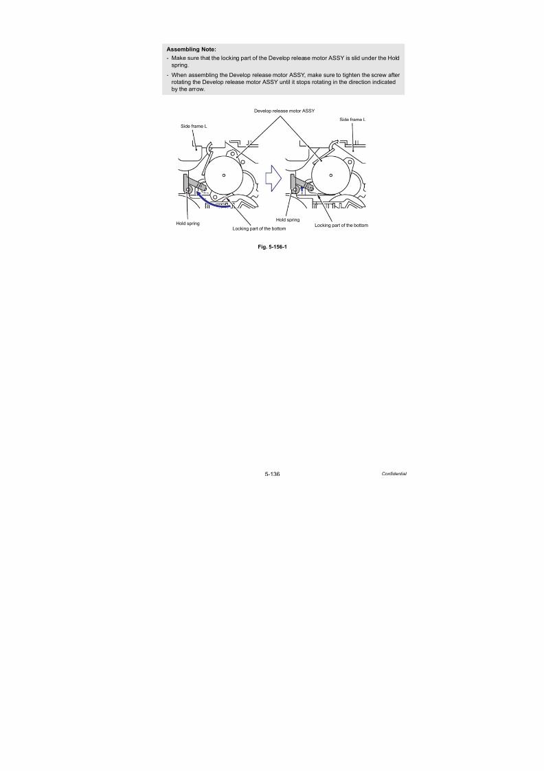
7/18/2019 Brother Mfc 9125cn 9325cw en 5694 Mfp Sm
http://slidepdf.com/reader/full/brother-mfc-9125cn-9325cw-en-5694-mfp-sm 363/597
5-136 Confidential
Fig. 5-156-1
Assembling Note:
- Make sure that the locking part of the Develop release motor ASSY is slid under the Hold
spring.
- When assembling the Develop release motor ASSY, make sure to tighten the screw after
rotating the Develop release motor ASSY until it stops rotating in the direction indicated
by the arrow.
Side frame L
Develop release motor ASSY
Side frame L
Hold springHold spring
Locking part of the bottomLocking part of the bottom

7/18/2019 Brother Mfc 9125cn 9325cw en 5694 Mfp Sm
http://slidepdf.com/reader/full/brother-mfc-9125cn-9325cw-en-5694-mfp-sm 364/597
5-137 Confidential
8.54 Main PCB ASSY
(1) Disconnect the seven Connectors (CN10, CN15, CN17, CN18, CN19, CN22, CN23) and
one flat cable (CN5) from the Main PCB ASSY.
Fig. 5-157
(2) Remove the four Taptite cup S M3x6 SR screws, and then remove the Main PCB ASSY
from the Main PCB shield plate.
Fig. 5-158
Note:
- After disconnecting the flat cable(s), check that each cable is not damaged at its endor short-circuited.
- When connecting the flat cable(s), do not insert it at an angle. After insertion, check
that the cable is not at an angle.
CN24 CN20
CN27
CN26
CN23 CN22 CN19 CN15 CN10
CN1
CN2
CN3
CN18
CN17
CN16 CN14 CN13 CN11 CN8
CN5
CN6
Main PCB ASSY
Main PCB shield plate
Main PCB ASSY
Main PCB shield plate
Main PCB ASSY
Taptite cup S M3x6 SR
2a
2b2a
2b
<Left side>

7/18/2019 Brother Mfc 9125cn 9325cw en 5694 Mfp Sm
http://slidepdf.com/reader/full/brother-mfc-9125cn-9325cw-en-5694-mfp-sm 365/597
5-138 Confidential
8.55 Engine PCB ASSY
(1) Disconnect the eleven connectors (CN1, CN2, CN4, CN6, CN7, CN8, CN9, CN10, CN11,
CN14, CN15) and one flat cable (CN3) from the Engine PCB ASSY.
Fig. 5-159
(2) Remove the four Taptite cup S M3x6 SR screws, and then remove the Engine PCB ASSYfrom the Side frame L.
Fig. 5-160
Note:
- After disconnecting the flat cable(s), check that each cable is not damaged at its endor short-circuited.
- When connecting the flat cable(s), do not insert it at an angle. After insertion, check
that the cable is not at an angle.
CN11
CN15CN14CN13
CN1
CN2
CN3
CN10
CN9
CN8 CN7 CN6 CN5CN4
Engine PCB ASSY
Engine PCB ASSY
Taptite cup S M3x6 SR
Side frame L
<Left side>
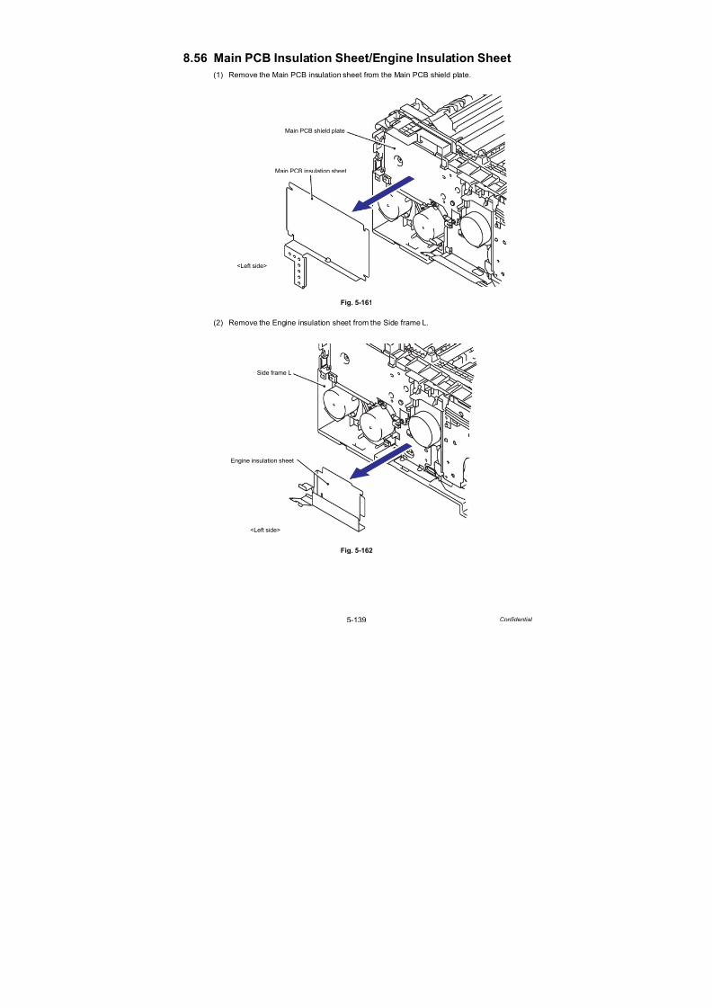
7/18/2019 Brother Mfc 9125cn 9325cw en 5694 Mfp Sm
http://slidepdf.com/reader/full/brother-mfc-9125cn-9325cw-en-5694-mfp-sm 366/597
5-139 Confidential
8.56 Main PCB Insulation Sheet/Engine Insulation Sheet
(1) Remove the Main PCB insulation sheet from the Main PCB shield plate.
Fig. 5-161
(2) Remove the Engine insulation sheet from the Side frame L.
Fig. 5-162
Main PCB shield plate
Main PCB insulation sheet
<Left side>
Side frame L
Engine insulation sheet
<Left side>

7/18/2019 Brother Mfc 9125cn 9325cw en 5694 Mfp Sm
http://slidepdf.com/reader/full/brother-mfc-9125cn-9325cw-en-5694-mfp-sm 367/597
5-140 Confidential
8.57 Main PCB Shield Plate
(1) Remove the three Taptite cup S M3x6 SR screws and one Taptite bind B M4x12 screw,
and then remove the Main PCB shield plate from the Side frame L.
Fig. 5-163
Taptite cup S M3x6 SR
Taptite bind B M4x12
Side frame L
Main PCB shield plate
Taptite cup SM3x6 SR
<Left side>
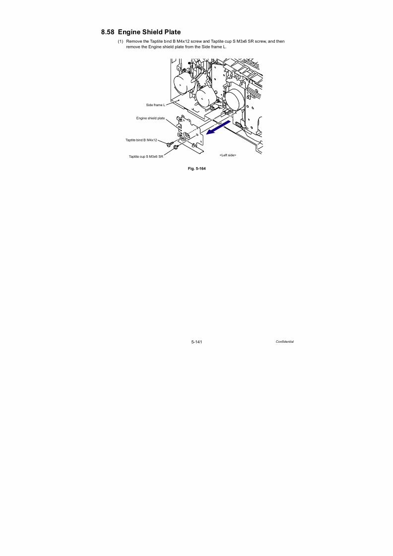
7/18/2019 Brother Mfc 9125cn 9325cw en 5694 Mfp Sm
http://slidepdf.com/reader/full/brother-mfc-9125cn-9325cw-en-5694-mfp-sm 368/597
5-141 Confidential
8.58 Engine Shield Plate
(1) Remove the Taptite bind B M4x12 screw and Taptite cup S M3x6 SR screw, and then
remove the Engine shield plate from the Side frame L.
Fig. 5-164
Taptite bind B M4x12
Taptite cup S M3x6 SR
Side frame L
Engine shield plate
<Left side>
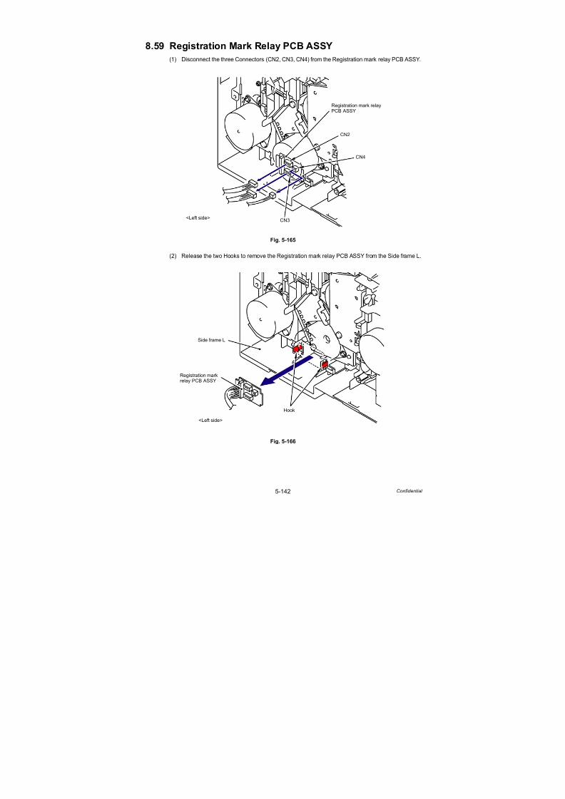
7/18/2019 Brother Mfc 9125cn 9325cw en 5694 Mfp Sm
http://slidepdf.com/reader/full/brother-mfc-9125cn-9325cw-en-5694-mfp-sm 369/597
5-142 Confidential
8.59 Registration Mark Relay PCB ASSY
(1) Disconnect the three Connectors (CN2, CN3, CN4) from the Registration mark relay PCB ASSY.
Fig. 5-165
(2) Release the two Hooks to remove the Registration mark relay PCB ASSY from the Side frame L.
Fig. 5-166
CN3
CN4
PCB ASSYRegistration mark relay
<Left side>
CN2
Hook
Side frame L
Registration markrelay PCB ASSY
<Left side>
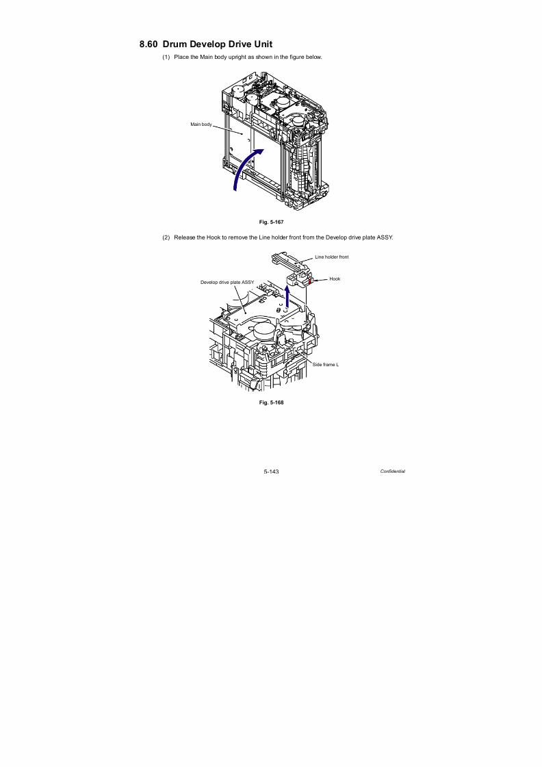
7/18/2019 Brother Mfc 9125cn 9325cw en 5694 Mfp Sm
http://slidepdf.com/reader/full/brother-mfc-9125cn-9325cw-en-5694-mfp-sm 370/597
5-143 Confidential
8.60 Drum Develop Drive Unit
(1) Place the Main body upright as shown in the figure below.
Fig. 5-167
(2) Release the Hook to remove the Line holder front from the Develop drive plate ASSY.
Fig. 5-168
Main body
HookDevelop drive plate ASSY
Line holder front
Side frame L
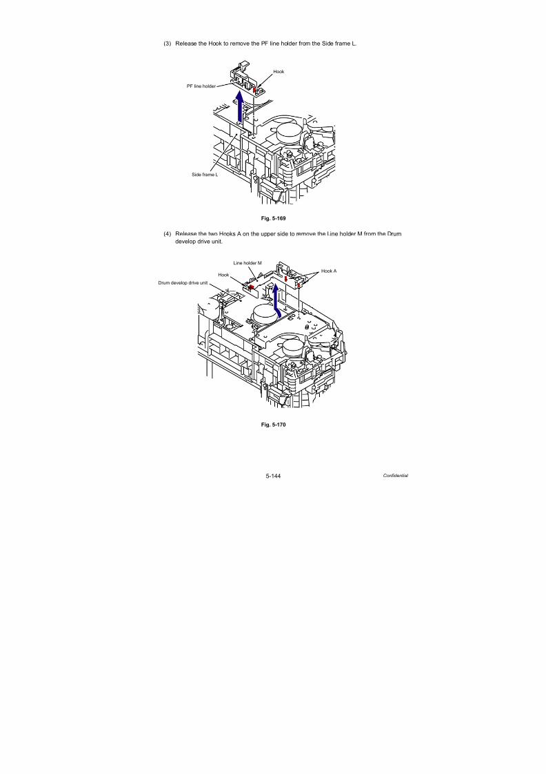
7/18/2019 Brother Mfc 9125cn 9325cw en 5694 Mfp Sm
http://slidepdf.com/reader/full/brother-mfc-9125cn-9325cw-en-5694-mfp-sm 371/597
5-144 Confidential
(3) Release the Hook to remove the PF line holder from the Side frame L.
Fig. 5-169
(4) Release the two Hooks A on the upper side to remove the Line holder M from the Drum
develop drive unit.
Fig. 5-170
Hook
Side frame L
PF line holder
Hook A
Drum develop drive unit
Line holder M
Hook

7/18/2019 Brother Mfc 9125cn 9325cw en 5694 Mfp Sm
http://slidepdf.com/reader/full/brother-mfc-9125cn-9325cw-en-5694-mfp-sm 372/597
5-145 Confidential
(5) Remove the two Taptite cup S M3x6 SR screws and two Taptite bind B M4x12 screws,
and then remove the Develop drive plate ASSY from the Side frame L.
Fig. 5-171
(6) Remove the one Gear 63/85, one Pendulum gear 50, one Idle gear 35, two Idle gear 30
and two Gear 42/39 from the Side frame L.
Fig. 5-172
Taptite cup S M3x6 SR
Taptite bind B M4x12
Side frame L
Develop drive plate ASSY
Side frame L
Gear 63/85 Pendulum gear 50
Idle gear 35
Idle gear 30
Gear 42/39

7/18/2019 Brother Mfc 9125cn 9325cw en 5694 Mfp Sm
http://slidepdf.com/reader/full/brother-mfc-9125cn-9325cw-en-5694-mfp-sm 373/597
5-146 Confidential
(7) Remove the two Taptite bind B M4x12 screws, and then remove the Under bar from the
Main body.
Fig. 5-173
(8) Remove the Taptite cup S M3x6 SR screw, and then remove the Under bar earth plate
from the Drum develop drive unit.
Fig. 5-174
Taptite bind B M4x12
Main body
Under bar
Taptite cup S M3x6 SR
Drum develop drive unit
Under bar earth plate

7/18/2019 Brother Mfc 9125cn 9325cw en 5694 Mfp Sm
http://slidepdf.com/reader/full/brother-mfc-9125cn-9325cw-en-5694-mfp-sm 374/597
5-147 Confidential
(9) Remove the three Taptite bind B M4x12 screws and two Taptite cup S M3x6 SR screws,
and then remove the Drum develop drive unit from the Side frame L.
Fig. 5-175
Harness routing: Refer to “ Paper Feed Motor ASSY, Drum Drive Motor.”
(10) Remove the Pendulum gear bush from the Drum develop drive unit.
Fig. 5-176
Taptite bind B M4x12Taptite cup S M3x6 SR
Side frame L
Pendulum gear bush
Taptite bind B M4x12
Drum develop drive unit
Pendulum gear bush
Drum develop drive unit

7/18/2019 Brother Mfc 9125cn 9325cw en 5694 Mfp Sm
http://slidepdf.com/reader/full/brother-mfc-9125cn-9325cw-en-5694-mfp-sm 375/597
5-148 Confidential
8.61 Develop Drive Motor
(1) Remove the three Screw bind M3x4, and then remove the Develop drive motor from the
Drum develop drive unit.
Fig. 5-177
Screw bind M3x4
Drum develop drive unit
Develop drive motor

7/18/2019 Brother Mfc 9125cn 9325cw en 5694 Mfp Sm
http://slidepdf.com/reader/full/brother-mfc-9125cn-9325cw-en-5694-mfp-sm 376/597
5-149 Confidential
8.62 Paper Feed Motor ASSY
(1) Remove the three Screw bind M3x4, and then remove the Paper feed motor ASSY from
the Drum develop drive unit.
Fig. 5-178
Harness routing: Refer to “ Paper Feed Motor ASSY, Drum Drive Motor.”
Assembling Note:
When replacing the Paper feed motor ASSY with a new one, fold the FFC first in
accordance with the “How to Fold FFC of Paper Feed Motor ASSY” figure in the next page,
and then assemble the Paper feed motor ASSY.
Screw bind M3x4
Drum develop drive unit
Paper feed motor ASSY
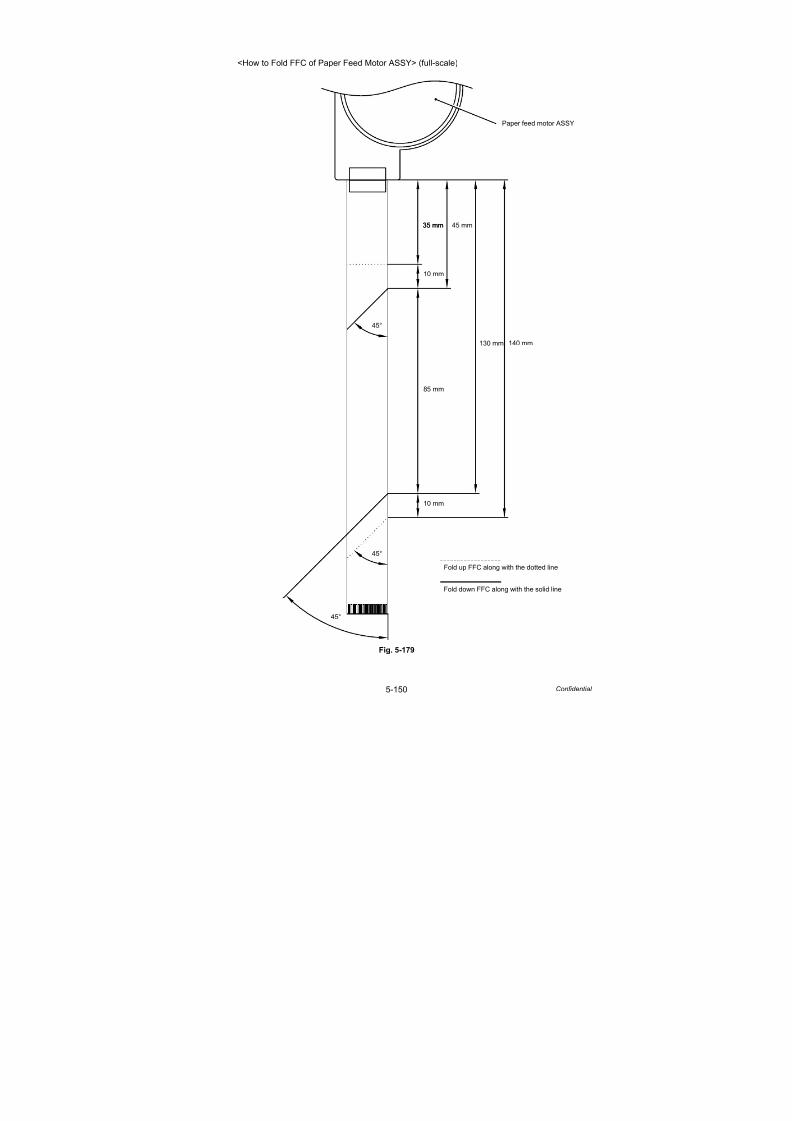
7/18/2019 Brother Mfc 9125cn 9325cw en 5694 Mfp Sm
http://slidepdf.com/reader/full/brother-mfc-9125cn-9325cw-en-5694-mfp-sm 377/597
5-150 Confidential
<How to Fold FFC of Paper Feed Motor ASSY> (full-scale)
Fig. 5-179
35 mm
10 mm
10 mm
45°
45°
45°
85 mm
130 mm
Paper feed motor ASSY
140 mm
Fold down FFC along with the solid line
Fold up FFC along with the dotted line
35 mm 45 mm

7/18/2019 Brother Mfc 9125cn 9325cw en 5694 Mfp Sm
http://slidepdf.com/reader/full/brother-mfc-9125cn-9325cw-en-5694-mfp-sm 378/597
5-151 Confidential
8.63 Paper Feed Unit
(1) Remove the Bush cap and Gear 24/28 from the Side frame L.
Fig. 5-180
(2) Release the Hook to remove the PF gear cap from the Side frame L.
Fig. 5-181
Side frame L
Bush cap
Gear 24/28
<Left side>
Hook
Side frame L
PF gear cap
<Left side>

7/18/2019 Brother Mfc 9125cn 9325cw en 5694 Mfp Sm
http://slidepdf.com/reader/full/brother-mfc-9125cn-9325cw-en-5694-mfp-sm 379/597
5-152 Confidential
(3) Remove the PF gear 17 and Separation roller drive shaft from the Side frame L.
Fig. 5-182
Gear position: Refer to “ Cleaner PF.”
(4) Remove the PF drive gear 23 and PF roller drive shaft TR from the Side frame L.
Fig. 5-183
Gear position: Refer to “ Cleaner PF.”
Side frame L
PF gear 17 <Left side>
Separation roller drive shaft
Side frame L
PF Drive gear 23 <Left side>
PF roller drive shaft TR
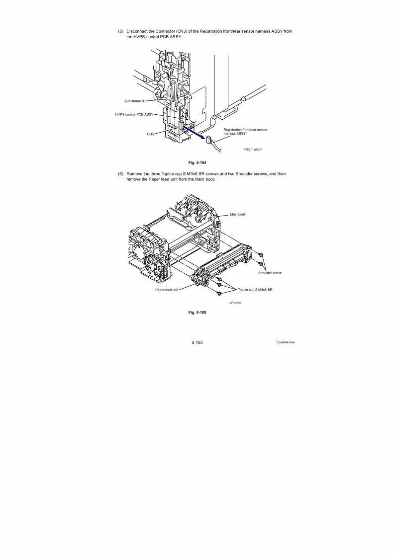
7/18/2019 Brother Mfc 9125cn 9325cw en 5694 Mfp Sm
http://slidepdf.com/reader/full/brother-mfc-9125cn-9325cw-en-5694-mfp-sm 380/597
5-153 Confidential
(5) Disconnect the Connector (CN3) of the Registration front/rear sensor harness ASSY from
the HVPS control PCB ASSY.
Fig. 5-184
(6) Remove the three Taptite cup S M3x6 SR screws and two Shoulder screws, and then
remove the Paper feed unit from the Main body.
Fig. 5-185
HVPS control PCB ASSY
CN3
Side frame R
Registration front/rear sensorharness ASSY
<Right side>
Taptite cup S M3x6 SR
Shoulder screw
Main body
Paper feed unit
<Front>

7/18/2019 Brother Mfc 9125cn 9325cw en 5694 Mfp Sm
http://slidepdf.com/reader/full/brother-mfc-9125cn-9325cw-en-5694-mfp-sm 381/597
5-154 Confidential
8.64 Registration Front/Rear Sensor PCB ASSY
(1) Remove the two Taptite cup B M3x10 screws from the PF upper cover ASSY.
(2) Keep the shutter part of the Registration rear actuator at the position shown in the figure below.
(3) Release the two Bosses to remove the PF upper cover ASSY from the Paper feed unit.
Fig. 5-186
(4) Disconnect the Connector (CN2) of the Manual sensor harness ASSY from the
Registration front/rear sensor PCB ASSY.
Fig. 5-187
Note:
When removing the PF upper cover ASSY, be careful not to damage the Registration
rear actuator.
PF upper cover ASSY
Taptite cup B M3x10
Taptite cup B M3x10
Paper feed unit
Boss
Registration rearPF upper cover ASSY
Shutter part
actuator
Boss
Registration front/rear sensor PCB ASSY
CN2
Manual sensor
Paper feed unit
harness ASSY

7/18/2019 Brother Mfc 9125cn 9325cw en 5694 Mfp Sm
http://slidepdf.com/reader/full/brother-mfc-9125cn-9325cw-en-5694-mfp-sm 382/597
5-155 Confidential
(5) Remove the Taptite cup B M3x8 screw from the Registration front/rear sensor PCB ASSY.
(6) Keep the shutter part of the Registration front actuator at the position shown in the figure below.
(7) Remove the Registration front/rear sensor PCB ASSY from the Paper feed frame.
Fig. 5-188
Harness routing: Refer to “ Registration Front/Rear Sensor PCB ASSY.”
Note:
When removing the Registration front/rear sensor PCB ASSY, be careful not todamage the Registration front actuator.
Registration front/rear sensor
Taptite cup B M3x8
PCB ASSY
Paper feed frame
Registration front actuator
Shutter part
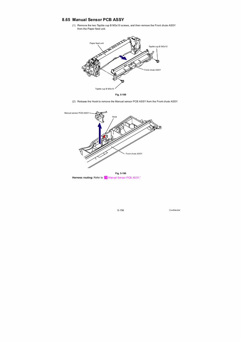
7/18/2019 Brother Mfc 9125cn 9325cw en 5694 Mfp Sm
http://slidepdf.com/reader/full/brother-mfc-9125cn-9325cw-en-5694-mfp-sm 383/597
5-156 Confidential
8.65 Manual Sensor PCB ASSY
(1) Remove the two Taptite cup B M3x10 screws, and then remove the Front chute ASSY
from the Paper feed unit.
Fig. 5-189
(2) Release the Hook to remove the Manual sensor PCB ASSY from the Front chute ASSY.
Fig. 5-190
Harness routing: Refer to “ Manual Sensor PCB ASSY.”
Paper feed unit
Front chute ASSY
Taptite cup B M3x10
Taptite cup B M3x10
Hook
Front chute ASSY
Manual sensor PCB ASSY

7/18/2019 Brother Mfc 9125cn 9325cw en 5694 Mfp Sm
http://slidepdf.com/reader/full/brother-mfc-9125cn-9325cw-en-5694-mfp-sm 384/597
5-157 Confidential
8.66 Pick-up Sector Gear Spring/Friction Spring
(1) Remove the Gear 27/72 from the Side frame L.
Fig. 5-191
(2) Remove the Pick-up sector gear spring from the Hook of the Cleaner PF gear cover.
Fig. 5-192
Side frame L
Gear 27/72
Cleaner PF gear cover Hook
Pick-up sector gear spring

7/18/2019 Brother Mfc 9125cn 9325cw en 5694 Mfp Sm
http://slidepdf.com/reader/full/brother-mfc-9125cn-9325cw-en-5694-mfp-sm 385/597

7/18/2019 Brother Mfc 9125cn 9325cw en 5694 Mfp Sm
http://slidepdf.com/reader/full/brother-mfc-9125cn-9325cw-en-5694-mfp-sm 386/597
5-159 Confidential
(4) Remove the Friction spring from the Cleaner PF gear cover.
Fig. 5-195
(5) Remove the Pick-up sector gear spring from the Side frame L.
Fig. 5-196
Cleaner PF gear cover
Friction spring
Side frame L
Pick-up sector gear spring

7/18/2019 Brother Mfc 9125cn 9325cw en 5694 Mfp Sm
http://slidepdf.com/reader/full/brother-mfc-9125cn-9325cw-en-5694-mfp-sm 387/597
5-160 Confidential
8.67 PF Registration Solenoid
(1) Remove the Pick-up sector gear 31/38 from the Side frame L.
Fig. 5-197
Fig. 5-198
Assembling Note:
When assembling the Pick-up sector gear 31/38 onto the Side frame L, make sure to mount
the Pick-up solenoid lever as shown in the figure below.
Side frame L
Pick-up sector gear 31/38
Pick-up sector gear 31/38
Pick-up solenoid lever
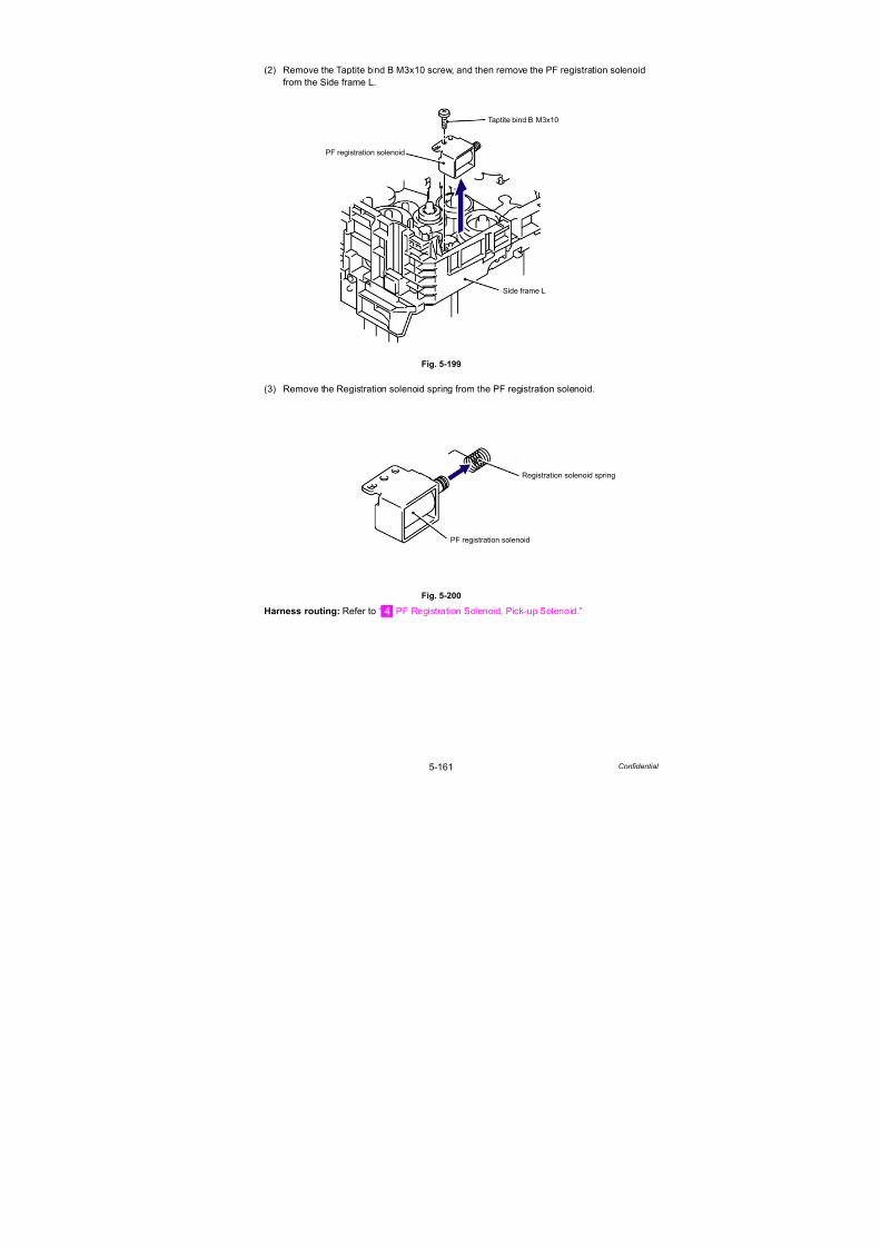
7/18/2019 Brother Mfc 9125cn 9325cw en 5694 Mfp Sm
http://slidepdf.com/reader/full/brother-mfc-9125cn-9325cw-en-5694-mfp-sm 388/597
5-161 Confidential
(2) Remove the Taptite bind B M3x10 screw, and then remove the PF registration solenoid
from the Side frame L.
Fig. 5-199
(3) Remove the Registration solenoid spring from the PF registration solenoid.
Fig. 5-200
Harness routing: Refer to “ PF Registration Solenoid, Pick-up Solenoid.”
Taptite bind B M3x10
Side frame L
PF registration solenoid
PF registration solenoid
Registration solenoid spring

7/18/2019 Brother Mfc 9125cn 9325cw en 5694 Mfp Sm
http://slidepdf.com/reader/full/brother-mfc-9125cn-9325cw-en-5694-mfp-sm 389/597
5-162 Confidential
8.68 Pick-up Solenoid/Pick-up Solenoid Lever Spring
(1) Remove the Idle gear 40 from the Side frame L.
Fig. 5-201
(2) Remove the Pick-up solenoid lever spring from the Hook of the Pick-up solenoid lever.
(3) Remove the Pick-up solenoid lever spring from the Side frame L.
Fig. 5-202
Note:
Be careful not to lose the Pick-up solenoid lever spring.
Side frame L
Idle gear 40
Pick-up solenoid lever
Hook
Pick-up solenoid lever spring
Side frame L
Pick-up solenoid
Hook
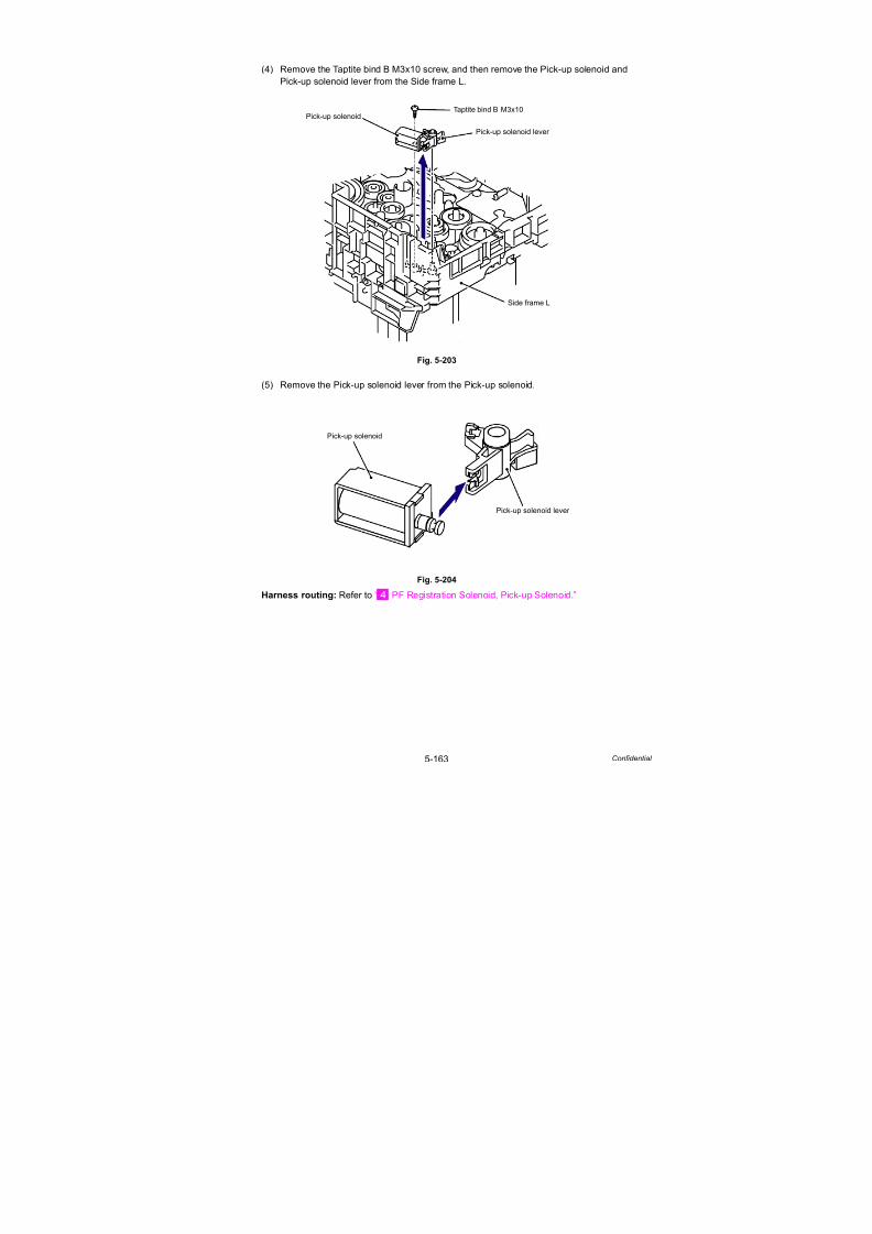
7/18/2019 Brother Mfc 9125cn 9325cw en 5694 Mfp Sm
http://slidepdf.com/reader/full/brother-mfc-9125cn-9325cw-en-5694-mfp-sm 390/597
5-163 Confidential
(4) Remove the Taptite bind B M3x10 screw, and then remove the Pick-up solenoid and
Pick-up solenoid lever from the Side frame L.
Fig. 5-203
(5) Remove the Pick-up solenoid lever from the Pick-up solenoid.
Fig. 5-204
Harness routing: Refer to “ PF Registration Solenoid, Pick-up Solenoid.”
Taptite bind B M3x10
Side frame L
Pick-up solenoid
Pick-up solenoid lever
Pick-up solenoid
Pick-up solenoid lever

7/18/2019 Brother Mfc 9125cn 9325cw en 5694 Mfp Sm
http://slidepdf.com/reader/full/brother-mfc-9125cn-9325cw-en-5694-mfp-sm 391/597
5-164 Confidential
8.69 Fuser/Eject Drive Motor
(1) Remove the Taptite bind B M4x12 screw and Taptite cup S M3x6 SR screw, and then
remove the Fuser/Eject drive motor from the Fuser eject drive ASSY.
Fig. 5-205
Harness routing: Refer to “ Fuser/Eject Drive Motor, Fuser/Eject Drive Motor Sensor PCB
ASSY.”
Fuser eject drive ASSY
Taptite cup S M3x6 SR
Taptite bind B M4x12
Fuser/Eject drive motor

7/18/2019 Brother Mfc 9125cn 9325cw en 5694 Mfp Sm
http://slidepdf.com/reader/full/brother-mfc-9125cn-9325cw-en-5694-mfp-sm 392/597
5-165 Confidential
8.70 Fuser/Eject Drive Motor Sensor PCB ASSY
(1) Remove the three Taptite bind B M4x12 screws, and then remove the Eject gear cover
from the Side frame L.
Fig. 5-206
(2) Release the Hook to remove the Fuser/eject drive motor sensor PCB ASSY from the
Eject gear cover.
Fig. 5-207
Harness routing: Refer to “ Fuser/Eject Drive Motor, Fuser/Eject Drive Motor Sensor PCB
ASSY.”
Note:
Be careful when changing the setup condition of the main body with the left side up whilethe Eject gear cover is removed because the gear may fall off.
Taptite bind B M4x12
Side frame L
Eject gear cover Taptite bind B M4x12
Hook
Hook
Hook
Eject gear cover
Fuser/eject drive motor sensor PCB ASSY
2b
2a
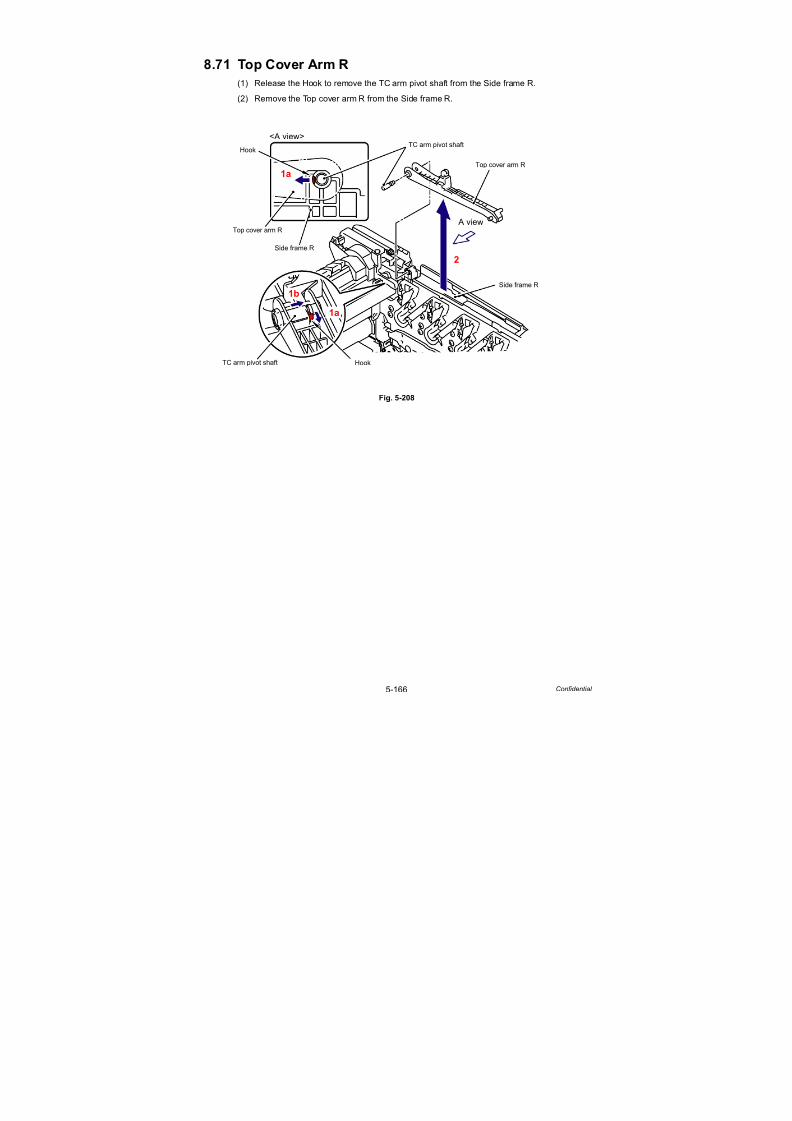
7/18/2019 Brother Mfc 9125cn 9325cw en 5694 Mfp Sm
http://slidepdf.com/reader/full/brother-mfc-9125cn-9325cw-en-5694-mfp-sm 393/597
5-166 Confidential
8.71 Top Cover Arm R
(1) Release the Hook to remove the TC arm pivot shaft from the Side frame R.
(2) Remove the Top cover arm R from the Side frame R.
Fig. 5-208
HookTC arm pivot shaft
Side frame R
Top cover arm R
Hook
Top cover arm R
TC arm pivot shaft
Side frame R
A view
<A view>
1a
1a
1b
2

7/18/2019 Brother Mfc 9125cn 9325cw en 5694 Mfp Sm
http://slidepdf.com/reader/full/brother-mfc-9125cn-9325cw-en-5694-mfp-sm 394/597
5-167 Confidential
8.72 Top Cover Arm L
(1) Release the Hook to remove the TC arm pivot shaft from the Side frame L.
(2) Remove the Top cover arm L from the Side frame L.
Fig. 5-209
Fig. 5-210
Assembling Note:
When assembling the Top cover arm L, make sure to fit the “A” of the Top cover arm L into
the “B” of the Top cover link 1 before assembling the Top cover arm L onto the Side frame L.
Hook
Top cover arm L
TC arm pivot shaft
Top cover arm L
Side frame L
A view
<A view>
1a
1a
1b
2
Top cover arm L
“A”
“B”
Top cover link 1

7/18/2019 Brother Mfc 9125cn 9325cw en 5694 Mfp Sm
http://slidepdf.com/reader/full/brother-mfc-9125cn-9325cw-en-5694-mfp-sm 395/597
5-168 Confidential
8.73 Air Filter Holder ASSY/Ozone Filter
(1) Remove the two Taptite bind B M4x12 screws from the Paper eject guide ASSY.
(2) Remove the two Taptite bind B M4x12 screws from the Side frame L and Side frame R.
Fig. 5-211
(3) Open the left and right frames to the outside and remove the Paper eject guide ASSYfrom the Main body.
Fig. 5-212
Paper eject guide ASSY
Taptite bind B M4x12
Taptite bind B M4x12
Taptite bind B M4x12 Side frame R
Side frame L
<Back side>
Paper eject guide ASSY
Side frame R
Side frame L
3a
3a
3b
<Back side>

7/18/2019 Brother Mfc 9125cn 9325cw en 5694 Mfp Sm
http://slidepdf.com/reader/full/brother-mfc-9125cn-9325cw-en-5694-mfp-sm 396/597
5-169 Confidential
(4) Release the two Hook A in the direction of the arrow 4a and remove the three Hook B in the
direction of the arrow 4b. Then, remove the Paper eject guide from the Lower air duct.
Fig. 5-213
Fig. 5-214
Assembling Note:
When assembling the Paper eject guide onto the Lower air duct, make sure to pass the
Eject rear harness ASSY through the “A” of the Lower air duct before assembling it.
Hook A
Lower air duct
Paper eject guide
Hook B
4b
4a
4c
Hook A
Lower air duct
“A”
Eject rear harness ASSY
Eject rear sensor
PCB ASSY
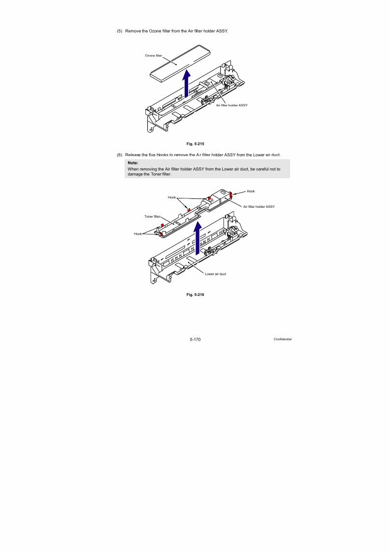
7/18/2019 Brother Mfc 9125cn 9325cw en 5694 Mfp Sm
http://slidepdf.com/reader/full/brother-mfc-9125cn-9325cw-en-5694-mfp-sm 397/597
5-170 Confidential
(5) Remove the Ozone filter from the Air filter holder ASSY.
Fig. 5-215
(6) Release the five Hooks to remove the Air filter holder ASSY from the Lower air duct.
Fig. 5-216
Note:
When removing the Air filter holder ASSY from the Lower air duct, be careful not to
damage the Toner filter.
Air filter holder ASSY
Ozone filter
Hook
Lower air duct
Air filter holder ASSY
Hook
Toner filter
Hook

7/18/2019 Brother Mfc 9125cn 9325cw en 5694 Mfp Sm
http://slidepdf.com/reader/full/brother-mfc-9125cn-9325cw-en-5694-mfp-sm 398/597
5-171 Confidential
8.74 Paper Eject Rear Actuator/Paper Eject Rear Actuator
Spring/Paper Eject Rear Actuator Top
(1) Remove “A” of the Paper eject rear actuator spring from the Hook of the Paper eject rear
actuator.
(2) Turn the Paper eject rear actuator to the direction of the arrow 2a and slide it to thedirection of the arrow 2b.
Adjust “B” of the Paper eject rear actuator to the position of “C” of the Lower air duct.
Then, remove the Paper eject rear actuator from the Lower air duct.
Fig. 5-217
Paper eject
Paper eject
Hook
Slit
Rib
Shutter
2b
2a
2a
rear actuator
Lower air duct
“A”
Paper eject rear
rear actuator
“B”
“C”
Lower air duct
Paper eject rear actuator
Paper ejectrear actuator
actuator spring
2c
1
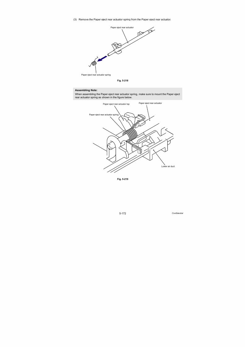
7/18/2019 Brother Mfc 9125cn 9325cw en 5694 Mfp Sm
http://slidepdf.com/reader/full/brother-mfc-9125cn-9325cw-en-5694-mfp-sm 399/597
5-172 Confidential
(3) Remove the Paper eject rear actuator spring from the Paper eject rear actuator.
Fig. 5-218
Fig. 5-219
Assembling Note:
When assembling the Paper eject rear actuator spring, make sure to mount the Paper eject
rear actuator spring as shown in the figure below.
Paper eject rear actuator
Paper eject rear actuator spring
Paper eject rear actuator
Paper eject rear actuator spring
Paper eject rear actuator top
Lower air duct

7/18/2019 Brother Mfc 9125cn 9325cw en 5694 Mfp Sm
http://slidepdf.com/reader/full/brother-mfc-9125cn-9325cw-en-5694-mfp-sm 400/597
5-173 Confidential
(4) Rotate the Paper eject rear actuator top in the direction of arrow 4a and remove the Paper
eject rear actuator top from the Paper eject rear actuator.
Fig. 5-220
Paper eject rear actuator top
Paper eject rear actuator
Paper eject rear actuator
Paper eject rearactuator top
Paper eject
Paper eject rearactuator top
4a
4b
4a4b
A view
<A view>
rear actuator
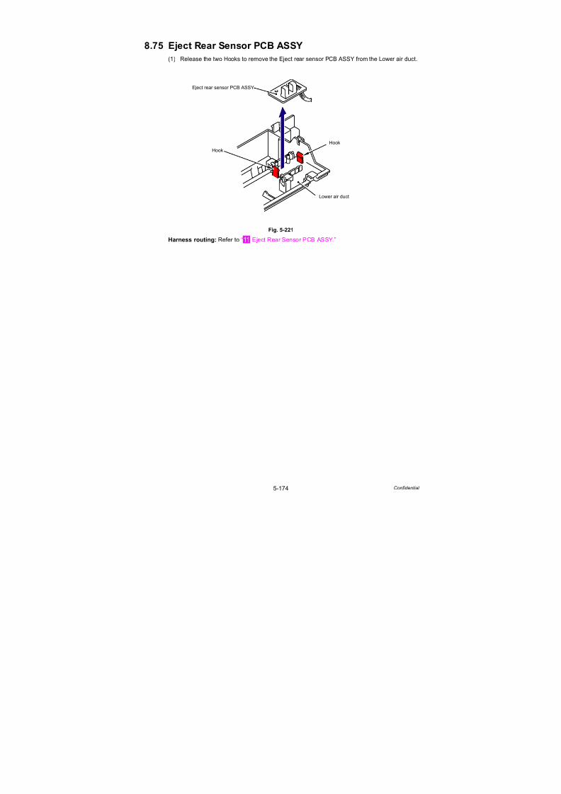
7/18/2019 Brother Mfc 9125cn 9325cw en 5694 Mfp Sm
http://slidepdf.com/reader/full/brother-mfc-9125cn-9325cw-en-5694-mfp-sm 401/597
5-174 Confidential
8.75 Eject Rear Sensor PCB ASSY
(1) Release the two Hooks to remove the Eject rear sensor PCB ASSY from the Lower air duct.
Fig. 5-221
Harness routing: Refer to “ Eject Rear Sensor PCB ASSY.”
Hook
Lower air duct
Eject rear sensor PCB ASSY
Hook

7/18/2019 Brother Mfc 9125cn 9325cw en 5694 Mfp Sm
http://slidepdf.com/reader/full/brother-mfc-9125cn-9325cw-en-5694-mfp-sm 402/597
5-175 Confidential
8.76 Eject Front Sensor PCB ASSY
(1) Release the Hook to remove the Eject front sensor PCB ASSY from the Side frame L.
Fig. 5-222
Harness routing: Refer to “ Eject Front Sensor PCB ASSY.”
Hook
Side frame L
Eject front sensor PCB ASSY
<Back side>

7/18/2019 Brother Mfc 9125cn 9325cw en 5694 Mfp Sm
http://slidepdf.com/reader/full/brother-mfc-9125cn-9325cw-en-5694-mfp-sm 403/597
5-176 Confidential
8.77 Toner/New Sensor PCB ASSY
(1) Release the five Hooks to remove the Toner/New sensor PCB ASSY from the Side frame L.
Fig. 5-223
(2) Release the Hooks of the PT sensor holder to remove the four PT sensor holder from the
Toner/New sensor PCB ASSY.
Fig. 5-224
Harness routing: Refer to “ Toner/New Sensor PCB ASSY.”
Hook
Side frame L
Toner/New sensor PCB ASSY
PT sensor holder
Toner/New sensor PCB ASSY
PT sensor holder
Hook
Hook
Hook
PT sensor holder

7/18/2019 Brother Mfc 9125cn 9325cw en 5694 Mfp Sm
http://slidepdf.com/reader/full/brother-mfc-9125cn-9325cw-en-5694-mfp-sm 404/597
5-177 Confidential
8.78 Belt Drive ASSY
(1) Remove the three Taptite pan (washer) B M4x12DA screws, and then remove the Belt
drive ASSY from the Side frame L.
Fig. 5-225
Harness routing: Refer to “ Belt Drive ASSY.”
Taptite pan (washer)
Side frame L
Belt drive ASSYB M4x12DA

7/18/2019 Brother Mfc 9125cn 9325cw en 5694 Mfp Sm
http://slidepdf.com/reader/full/brother-mfc-9125cn-9325cw-en-5694-mfp-sm 405/597
5-178 Confidential
8.79 Drum Motor Origin Sensor PCB ASSY
(1) Remove the Taptite bind B M3x10 screw, and then remove the Drum motor origin sensor
PCB ASSY from the Side frame L.
Fig. 5-226
Harness routing: Refer to “ Drum Motor Origin Sensor PCB ASSY.”
Taptite bind B M3x10
Side frame L
Drum motor originsensor PCB ASSY
<Left side>

7/18/2019 Brother Mfc 9125cn 9325cw en 5694 Mfp Sm
http://slidepdf.com/reader/full/brother-mfc-9125cn-9325cw-en-5694-mfp-sm 406/597
5-179 Confidential
8.80 LV Fan ASSY
(1) Remove the two Taptite bind B M4x12 screws, and then remove the NCU harness holder
from the Side frame R.
Fig. 5-227
(2) Remove the Taptite bind B M4x12 screw from the Safety louver.
(3) Release the two Hooks to remove the Safety louver from the Side frame R.
Fig. 5-228
Note:
Do not pull the Safety louver strongly because it has the Power supply switch on it.
Taptite bind B M4x12
Side frame R
NCU harness holder
Taptite bind B M4x12
<Right side>
Taptite bind B M4x12
Hook
Side frame R
Hook
Safety louver
<Right side>
Power supply switch

7/18/2019 Brother Mfc 9125cn 9325cw en 5694 Mfp Sm
http://slidepdf.com/reader/full/brother-mfc-9125cn-9325cw-en-5694-mfp-sm 407/597
5-180 Confidential
(4) Disconnect the Connector (CN3) from the High-voltage power supply PCB ASSY.
Fig. 5-229
(5) Remove the LV fan ASSY from the Side frame R.
Fig. 5-230
Harness routing: Refer to “ Main Fan ASSY, LV Fan ASSY.”
Assembling Note:
When assembling the LV fan ASSY, place it so that the attached label faces outwards.
High-voltage power supply
Connector
CN3
PCB ASSY
<Right side>
Side frame R
LV fan ASSY
<Right side>

7/18/2019 Brother Mfc 9125cn 9325cw en 5694 Mfp Sm
http://slidepdf.com/reader/full/brother-mfc-9125cn-9325cw-en-5694-mfp-sm 408/597
5-181 Confidential
8.81 Main Fan ASSY
(1) Disconnect the Connector (CN2) of the Main fan ASSY from the High-voltage power
supply PCB ASSY.
Fig. 5-231
(2) Remove the Main fan ASSY from the Side frame R.
Fig. 5-232
Harness routing: Refer to “ Main Fan ASSY, LV Fan ASSY.”
Assembling Note:
When assembling the Main fan ASSY, place it so that the attached label faces outwards.
High-voltage power supply PCB ASSYMain fan ASSY
Connector
Side frame R
CN2<Right side>
Side frame R
Main fan ASSY
<Right side>
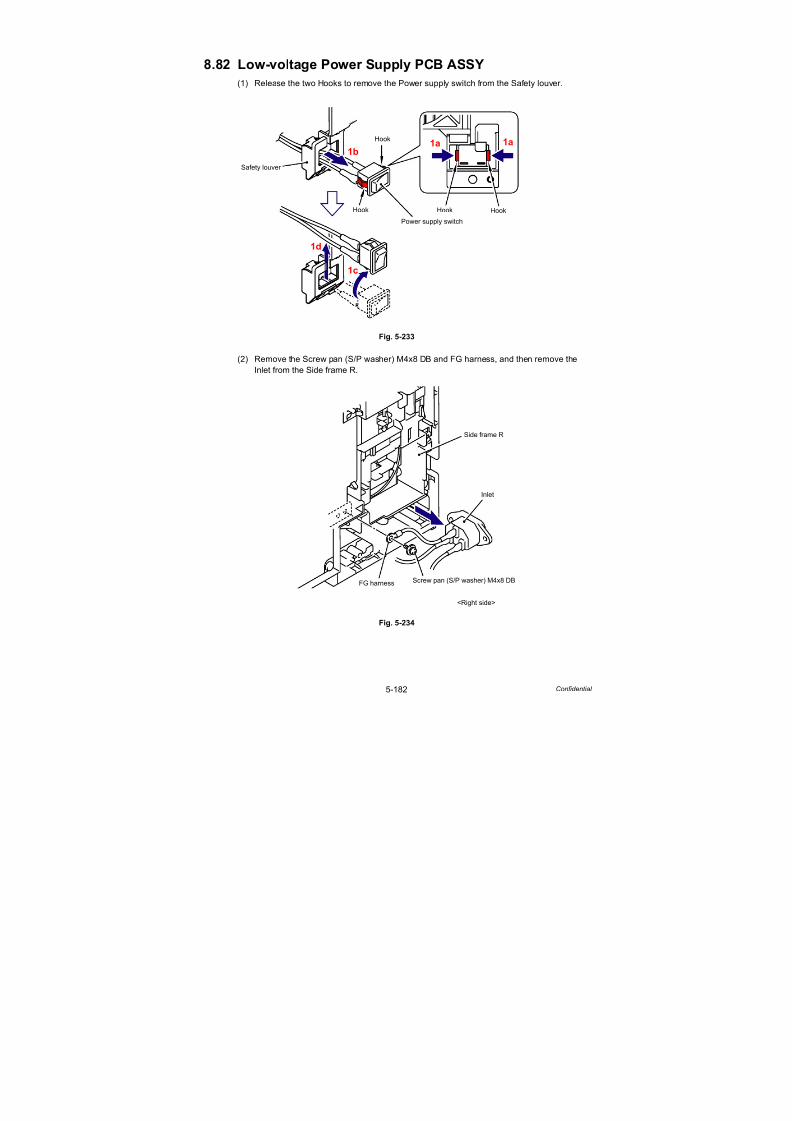
7/18/2019 Brother Mfc 9125cn 9325cw en 5694 Mfp Sm
http://slidepdf.com/reader/full/brother-mfc-9125cn-9325cw-en-5694-mfp-sm 409/597
5-182 Confidential
8.82 Low-voltage Power Supply PCB ASSY
(1) Release the two Hooks to remove the Power supply switch from the Safety louver.
Fig. 5-233
(2) Remove the Screw pan (S/P washer) M4x8 DB and FG harness, and then remove the
Inlet from the Side frame R.
Fig. 5-234
Hook
Power supply switch
Safety louver
Hook
Hook Hook
1a1a1b
1c
1d
Screw pan (S/P washer) M4x8 DB
Side frame R
Inlet
FG harness
<Right side>
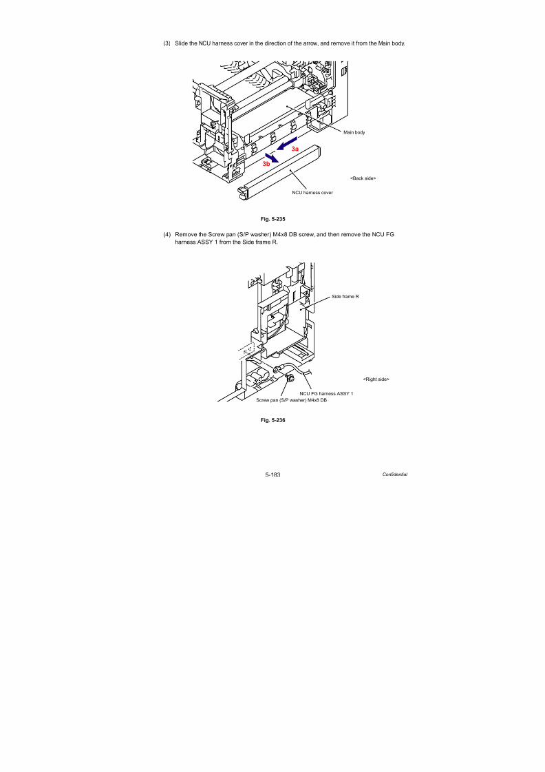
7/18/2019 Brother Mfc 9125cn 9325cw en 5694 Mfp Sm
http://slidepdf.com/reader/full/brother-mfc-9125cn-9325cw-en-5694-mfp-sm 410/597
5-183 Confidential
(3) Slide the NCU harness cover in the direction of the arrow, and remove it from the Main body.
Fig. 5-235
(4) Remove the Screw pan (S/P washer) M4x8 DB screw, and then remove the NCU FG
harness ASSY 1 from the Side frame R.
Fig. 5-236
Main body
NCU harness cover
<Back side>
3a
3b
Screw pan (S/P washer) M4x8 DB
Side frame R
NCU FG harness ASSY 1
<Right side>
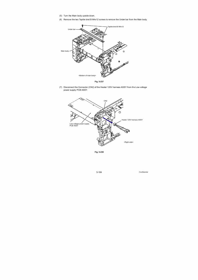
7/18/2019 Brother Mfc 9125cn 9325cw en 5694 Mfp Sm
http://slidepdf.com/reader/full/brother-mfc-9125cn-9325cw-en-5694-mfp-sm 411/597
5-184 Confidential
(5) Turn the Main body upside down.
(6) Remove the two Taptite bind B M4x12 screws to remove the Under bar from the Main body.
Fig. 5-237
(7) Disconnect the Connector (CN2) of the Heater 120V harness ASSY from the Low-voltage
power supply PCB ASSY.
Fig. 5-238
Taptite bind B M4x12
Main body
Under bar
<Bottom of main body>
Low-voltage power supply
Heater 120V harness ASSY
CN2
<Right side>
PCB ASSY

7/18/2019 Brother Mfc 9125cn 9325cw en 5694 Mfp Sm
http://slidepdf.com/reader/full/brother-mfc-9125cn-9325cw-en-5694-mfp-sm 412/597
5-185 Confidential
(8) Remove the two Taptite bind B M4x12 screws and two Taptite cup S M3x6 SR screws,
and then remove the LVPS unit from the Main body.
Fig. 5-239
Fig. 5-240
Assembling Note:
When assembling the LVPS unit onto the Main body, make sure to assemble it in a way that
the LVPS plate is placed at a lower position than the Middle plate.
Taptite bind B M4x12
Main body
LVPS unit
Middle plate
Taptite cup S M3x6 SR
<Back side>
LVPS unit
LVPS plate Middle plate
LVPS plate
LVPS unit
Middle plate
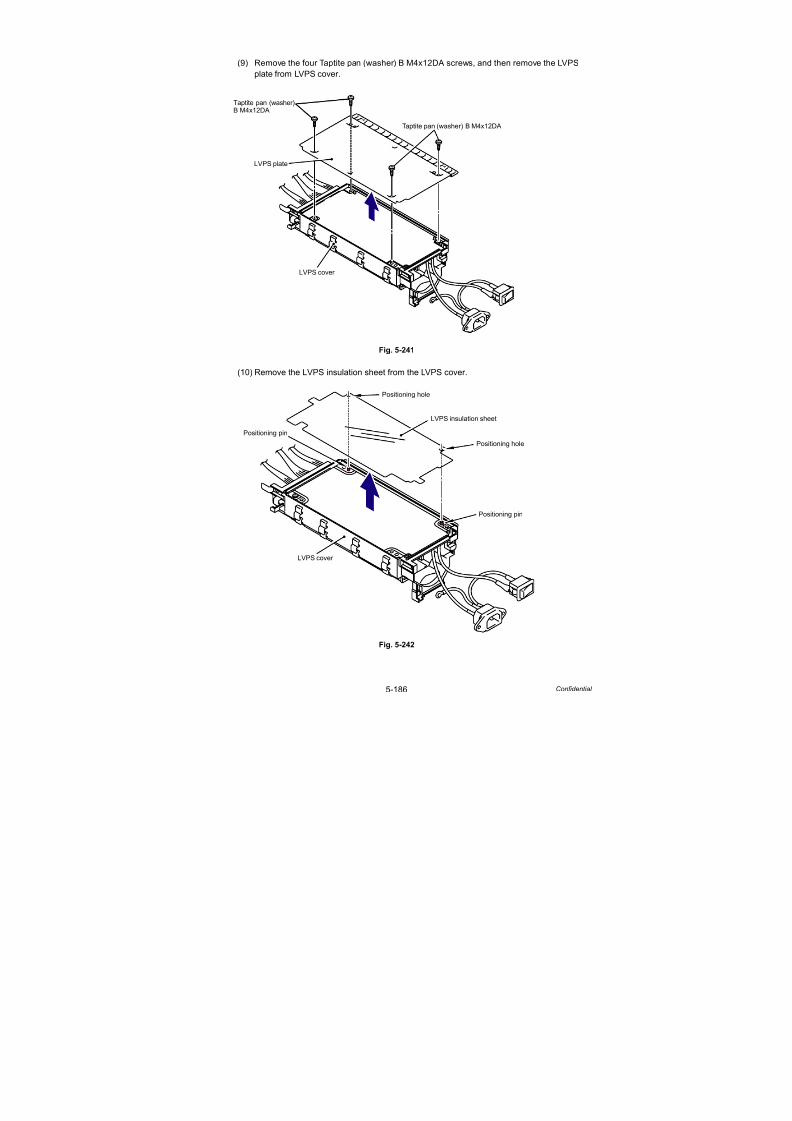
7/18/2019 Brother Mfc 9125cn 9325cw en 5694 Mfp Sm
http://slidepdf.com/reader/full/brother-mfc-9125cn-9325cw-en-5694-mfp-sm 413/597
5-186 Confidential
(9) Remove the four Taptite pan (washer) B M4x12DA screws, and then remove the LVPS
plate from LVPS cover.
Fig. 5-241
(10) Remove the LVPS insulation sheet from the LVPS cover.
Fig. 5-242
Taptite pan (washer) B M4x12DA
Taptite pan (washer)
LVPS cover
LVPS plate
B M4x12DA
LVPS insulation sheet
Positioning pin
Positioning pin
Positioning hole
Positioning hole
LVPS cover

7/18/2019 Brother Mfc 9125cn 9325cw en 5694 Mfp Sm
http://slidepdf.com/reader/full/brother-mfc-9125cn-9325cw-en-5694-mfp-sm 414/597
5-187 Confidential
(11) Remove the Taptite pan (washer) B M4x12DA screw, and then remove the Low-voltage
power supply PCB ASSY from the LVPS cover.
Fig. 5-243
(12) Disconnect the three Connectors (CN101, CN102, CN103) from the Low-voltage power
supply PCB ASSY.
Fig. 5-243-1Harness routing: Refer to “ Low-voltage Power Supply PCB ASSY.”
LVPS cover
Low-voltage power supply PCB ASSY
Taptite pan (washer)B M4x12DA
Low-voltage power supply PCB ASSY
CN101
CN102
CN103

7/18/2019 Brother Mfc 9125cn 9325cw en 5694 Mfp Sm
http://slidepdf.com/reader/full/brother-mfc-9125cn-9325cw-en-5694-mfp-sm 415/597
5-188 Confidential
8.83 Registration Sensor Holder ASSY
(1) Remove the Taptite cup S M3x6 SR screw from the Registration sensor holder ASSY.
Fig. 5-244
(2) Wire the harness and release the Hook. Slide the Registration sensor holder ASSY in the
direction of the arrow 2a, and remove it from the Registration sensor plate.
Fig. 5-245
Harness routing: Refer to “ Registration Sensor Holder ASSY.”
Assembling Note:
- Be careful not to place the harness between the Registration sensor holder ASSY and the
Registration sensor plate when assembling the Registration sensor holder ASSY to the
Registration sensor plate.
- A reinforcement plate for transportation is assembled to the Registration sensor holder
ASSY (service part). Remove the reinforcement plate for transportation from the
Registration sensor holder ASSY before assembling.
Registration sensor holder ASSY
Taptite cup S M3x6 SR
<Right side>
<Left side>
Hook
Registration sensor plate
Registration sensor holder ASSY
2b
2a
<A view>
A view
Registration sensor plate
<Right side>
<Left side>
2a

7/18/2019 Brother Mfc 9125cn 9325cw en 5694 Mfp Sm
http://slidepdf.com/reader/full/brother-mfc-9125cn-9325cw-en-5694-mfp-sm 416/597
5-189 Confidential
8.84 High-voltage Power Supply PCB ASSY
(1) Remove the two Taptite bind B M4x12 screws and two Taptite pan (washer) B M4x12DA
screws from the High-voltage power supply PCB ASSY.
Fig. 5-246
(2) Remove the Taptite cup S M3x6 SR screw, and then remove the HVPS ground plate 2
from the High-voltage power supply PCB ASSY.
Fig. 5-247
High-voltage power
Taptite bind B M4x12
Taptite bind B M4x12
Taptite pan (washer) B M4x12DA
supply PCB ASSY
HVPS ground plate 2Taptite cup S M3x6 SR
High-voltage power supply PCB ASSY

7/18/2019 Brother Mfc 9125cn 9325cw en 5694 Mfp Sm
http://slidepdf.com/reader/full/brother-mfc-9125cn-9325cw-en-5694-mfp-sm 417/597
5-190 Confidential
(3) Disconnect the Flat cable (CN7) of the High-voltage power supply PCB ASSY from the
HVPS control PCB ASSY.
Fig. 5-248
(4) Remove the two Spacer from the High-voltage power supply PCB ASSY.
Fig. 5-249
Note:
- After disconnecting the flat cable(s), check that each cable is not damaged at its end
or short-circuited.
- When connecting the flat cable(s), do not insert it at an angle. After insertion, checkthat the cable is not at an angle.
HVPS control PCB ASSY
High-voltage power
Flat cable
CN7
supply PCB ASSY
Side frame R
Spacer
High-voltage powersupply PCB ASSY
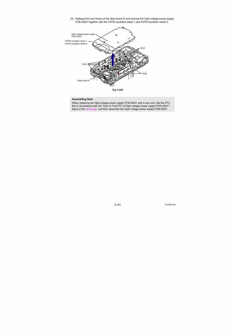
7/18/2019 Brother Mfc 9125cn 9325cw en 5694 Mfp Sm
http://slidepdf.com/reader/full/brother-mfc-9125cn-9325cw-en-5694-mfp-sm 418/597
5-191 Confidential
(5) Release the nine Hooks of the Side frame R, and remove the High-voltage power supply
PCB ASSY together with the HVPS insulation sheet 1 and HVPS insulation sheet 2.
Fig. 5-250
Assembling Note:
When replacing the High-voltage power supply PCB ASSY with a new one, fold the FFC
first in accordance with the “How to Fold FFC of High-voltage power supply PCB ASSY”
figure in the next page, and then assemble the High-voltage power supply PCB ASSY.
Side frame R
Hook
High-voltage power supply
Hook
Hook
PCB ASSY
HVPS insulation sheet 1
HVPS insulation sheet 2

7/18/2019 Brother Mfc 9125cn 9325cw en 5694 Mfp Sm
http://slidepdf.com/reader/full/brother-mfc-9125cn-9325cw-en-5694-mfp-sm 419/597
5-192 Confidential
<How to Fold FFC of High-voltage power supply PCB ASSY FFC> (full-scale)
Fig. 5-251
45 °
45 °
3 mm
High-voltage power supply PCB ASSY
41 mm
202 mm
185 mm
157 mm
High-voltage power supply PCB ASSY
FFC
Fold down FFC along with the solid line
Fold up FFC along with the dotted line

7/18/2019 Brother Mfc 9125cn 9325cw en 5694 Mfp Sm
http://slidepdf.com/reader/full/brother-mfc-9125cn-9325cw-en-5694-mfp-sm 420/597
5-193 Confidential
(6) Remove the HVPS insulation sheet 2 from the High-voltage power supply PCB ASSY.
Fig. 5-252
(7) Remove the HVPS insulation sheet 1 from the High-voltage power supply PCB ASSY.
Fig. 5-253
High-voltage power supply PCB ASSY
HVPS insulation sheet 2
High-voltage power supply PCB ASSY
HVPS insulation sheet 1
7b
7a

7/18/2019 Brother Mfc 9125cn 9325cw en 5694 Mfp Sm
http://slidepdf.com/reader/full/brother-mfc-9125cn-9325cw-en-5694-mfp-sm 421/597
5-194 Confidential
Fig. 5-254
Assembling Note:
When assembling the HVPS insulation sheet 1 and HVPS insulation sheet 2, make sure to
assemble them as sandwiching the Flat cable of the High-voltage power supply PCB ASSY
with them.
HVPS insulation sheet 2
HVPS insulation sheet 1
High-voltage power supplyFlat cable PCB ASSY

7/18/2019 Brother Mfc 9125cn 9325cw en 5694 Mfp Sm
http://slidepdf.com/reader/full/brother-mfc-9125cn-9325cw-en-5694-mfp-sm 422/597
5-195 Confidential
8.85 HVPS Control PCB ASSY
(1) Disconnect the six Connectors (CN1, CN4, CN5, CN8, CN9, CN10) from the HVPS
control PCB ASSY.
Fig. 5-255
(2) Remove the Taptite pan (S/P W) B M3x10 screw, and then remove the HVPS control PCB
ASSY from the Side frame R.
Fig. 5-256
CN1
CN8
CN3
CN10
CN9
CN7
CN5
CN4
HVPS control PCB ASSY
HVPS control PCB ASSY
Taptite pan (S/P W) B M3x10
Side frame R
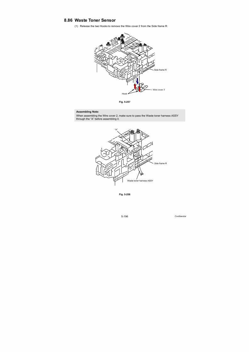
7/18/2019 Brother Mfc 9125cn 9325cw en 5694 Mfp Sm
http://slidepdf.com/reader/full/brother-mfc-9125cn-9325cw-en-5694-mfp-sm 423/597
5-196 Confidential
8.86 Waste Toner Sensor
(1) Release the two Hooks to remove the Wire cover 2 from the Side frame R.
Fig. 5-257
Fig. 5-258
Assembling Note:
When assembling the Wire cover 2, make sure to pass the Waste toner harness ASSY
through the “A” before assembling it.
Wire cover 2
Hook
Side frame R
Side frame R
“A”
Waste toner harness ASSY

7/18/2019 Brother Mfc 9125cn 9325cw en 5694 Mfp Sm
http://slidepdf.com/reader/full/brother-mfc-9125cn-9325cw-en-5694-mfp-sm 424/597
5-197 Confidential
(2) Press the Pin of the Waste toner sensor holder and slide the Waste toner sensor holder to
the left.
Fig. 5-259
(3) Remove the Waste toner sensor holder from the Middle plate sub ASSY as shown in the
figure below.
Fig. 5-260
Pin
Waste toner sensor holder
Pin
Waste toner sensor holder
Hook
Middle plate sub ASSY
Middle plate sub ASSY
A view
<A view>
<Left side>
Middle plate sub ASSYWaste toner sensor
Middle plate sub ASSY
Waste toner sensor holder
3a
3b
A view
<A view>
holder
3a

7/18/2019 Brother Mfc 9125cn 9325cw en 5694 Mfp Sm
http://slidepdf.com/reader/full/brother-mfc-9125cn-9325cw-en-5694-mfp-sm 425/597
5-198 Confidential
(4) Release the three Hooks to remove the Waste toner sensor from the Waste toner sensor holder.
Fig. 5-261
(5) Disconnect the Connector of the Waste toner harness ASSY from the Waste toner sensor.
Fig. 5-262
Harness routing: Refer to “ Waste Toner Sensor.”
Waste toner sensor holder
Hook
Waste toner sensor
Hook
Hook
Waste toner sensor
Waste toner harness ASSY

7/18/2019 Brother Mfc 9125cn 9325cw en 5694 Mfp Sm
http://slidepdf.com/reader/full/brother-mfc-9125cn-9325cw-en-5694-mfp-sm 426/597
5-199 Confidential
8.87 Develop Release Sensor PCB ASSY
(1) Remove the Film from the Side frame R.
Fig. 5-263
(2) Remove the Taptite cup B M3x8 screw, and then release the Hook to remove the Develop
release sensor PCB ASSY from the Side frame R.
Fig. 5-264
Harness routing: Refer to “ Develop Release Sensor PCB ASSY, Top Cover Open Switch,
Toner LED PCB ASSY.”
Side frame R
Film
Side frame R
Develop release sensor PCB ASSY
Hook
Taptite cup B M3x8

7/18/2019 Brother Mfc 9125cn 9325cw en 5694 Mfp Sm
http://slidepdf.com/reader/full/brother-mfc-9125cn-9325cw-en-5694-mfp-sm 427/597
5-200 Confidential
8.88 Belt Cleaner Spring
(1) Remove the four Electrode head 1 and four Electrode spring 1 from the Side frame R.
Fig. 5-265
(2) Remove the four Electrode spring 2 from the Side frame R.
Fig. 5-266
Side frame R
Electrode head 1
Electrode spring 1
Side frame R
Electrode spring 2
Boss
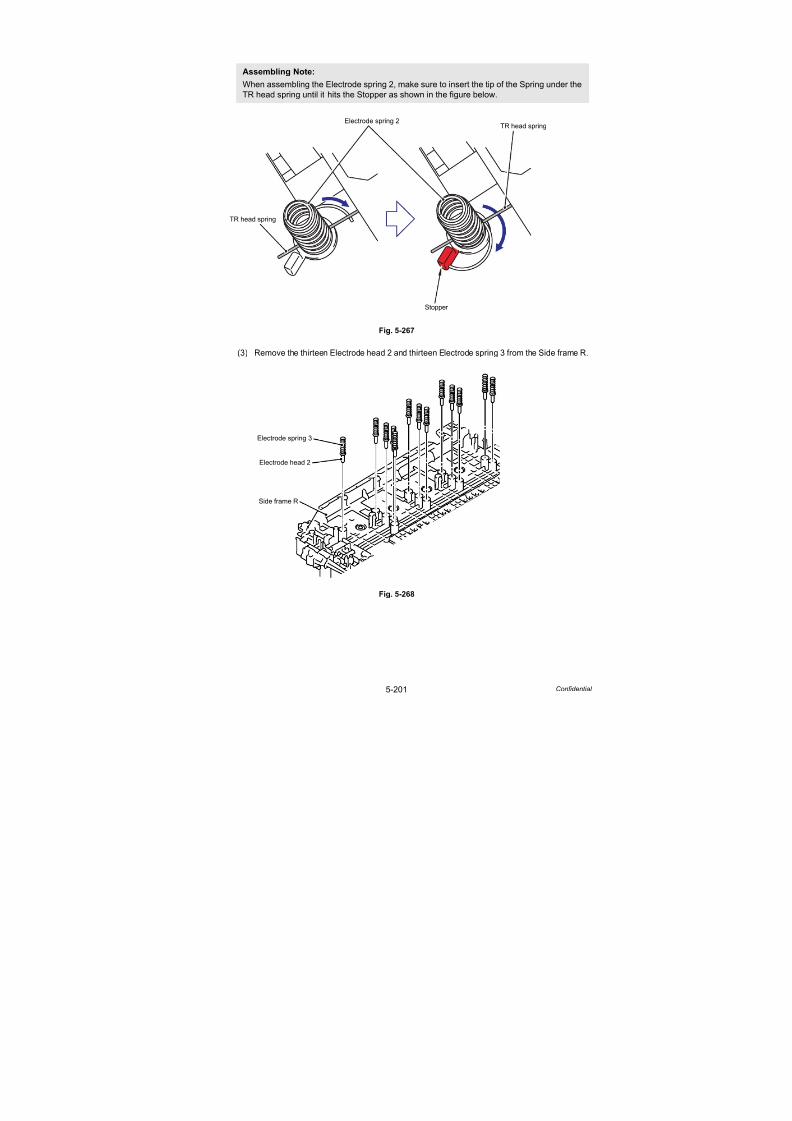
7/18/2019 Brother Mfc 9125cn 9325cw en 5694 Mfp Sm
http://slidepdf.com/reader/full/brother-mfc-9125cn-9325cw-en-5694-mfp-sm 428/597
5-201 Confidential
Fig. 5-267
(3) Remove the thirteen Electrode head 2 and thirteen Electrode spring 3 from the Side frame R.
Fig. 5-268
Assembling Note:
When assembling the Electrode spring 2, make sure to insert the tip of the Spring under the
TR head spring until it hits the Stopper as shown in the figure below.
Electrode spring 2
Stopper
TR head spring
TR head spring
Side frame R
Electrode head 2
Electrode spring 3

7/18/2019 Brother Mfc 9125cn 9325cw en 5694 Mfp Sm
http://slidepdf.com/reader/full/brother-mfc-9125cn-9325cw-en-5694-mfp-sm 429/597
5-202 Confidential
(4) Remove the two Electrode head 2 and two Belt cleaner spring from the Side frame R.
Fig. 5-269
(5) Remove the two Belt cleaner springs from the two Electrode head 2.
Fig. 5-270
Side frame R
Electrode head 2
Belt cleaner spring 3
Electrode head 2
Belt cleaner spring
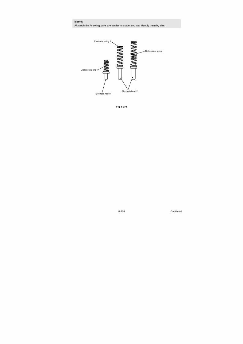
7/18/2019 Brother Mfc 9125cn 9325cw en 5694 Mfp Sm
http://slidepdf.com/reader/full/brother-mfc-9125cn-9325cw-en-5694-mfp-sm 430/597
5-203 Confidential
Fig. 5-271
Memo:
Although the following parts are similar in shape, you can identify them by size.
Electrode head 2Electrode head 1
Electrode spring 1
Electrode spring 3
Belt cleaner spring

7/18/2019 Brother Mfc 9125cn 9325cw en 5694 Mfp Sm
http://slidepdf.com/reader/full/brother-mfc-9125cn-9325cw-en-5694-mfp-sm 431/597
5-204 Confidential
8.89 TR Head Spring
(1) Release the four Hooks, slide the TR head cover in the direction of the arrow 1a, and
remove it from the Side frame R in the direction of the arrow 1b.
Fig. 5-272
(2) Remove the four Electrode head 2 and four TR head spring from the Side frame R.
Fig. 5-273
Side frame R
Hook
TR head cover
1a
Hook
Hook
1b
Side frame R
Electrode head 2
TR head spring

7/18/2019 Brother Mfc 9125cn 9325cw en 5694 Mfp Sm
http://slidepdf.com/reader/full/brother-mfc-9125cn-9325cw-en-5694-mfp-sm 432/597
5-205 Confidential
Fig. 5-274
(3) Remove the TR head spring from the four Electrode heads 2 (four springs in total).
Fig. 5-275
Assembling Note:
When assembling the Electrode head 2 and TR head spring onto the Side frame R, make
sure to assemble them as shown in the figure below.
Electrode head 2
TR head spring
Electrode head 2
Hook
Hook
Hook
Electrode head 2
TR head spring

7/18/2019 Brother Mfc 9125cn 9325cw en 5694 Mfp Sm
http://slidepdf.com/reader/full/brother-mfc-9125cn-9325cw-en-5694-mfp-sm 433/597
5-206 Confidential
8.90 Side Frame R
(1) Remove the four Shoulder screws M3, and then remove the Side frame R from the Base
frame unit.
Fig. 5-276
(2) Remove the HVPS ground plate 1 from the Side frame R.
Fig. 5-277
Shoulder screw M3
Base frame unit
Side frame R
1a
1b
Side frame R
HVPS ground plate 1
2a
2b

7/18/2019 Brother Mfc 9125cn 9325cw en 5694 Mfp Sm
http://slidepdf.com/reader/full/brother-mfc-9125cn-9325cw-en-5694-mfp-sm 434/597
5-207 Confidential
(3) Release the two Hooks of the Top cover open switch to remove the Top cover open switch
from the Side frame R.
Fig. 5-278
Harness routing: Refer to “ Develop Release Sensor PCB ASSY, Top Cover Open Switch,
Toner LED PCB ASSY.”
(4) Release the Hook of the Lock arm from the Side frame R.
Fig. 5-279
Hook
Side frame R
Top cover open switchHook
Hook
Hook
Top cover open switch
3a3a
3b
Hook
Hook
Side frame R
Side frame R
Lock arm
4a
4b
Lock arm
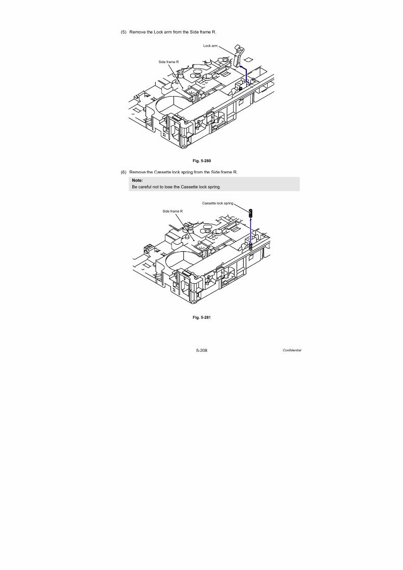
7/18/2019 Brother Mfc 9125cn 9325cw en 5694 Mfp Sm
http://slidepdf.com/reader/full/brother-mfc-9125cn-9325cw-en-5694-mfp-sm 435/597
5-208 Confidential
(5) Remove the Lock arm from the Side frame R.
Fig. 5-280
(6) Remove the Cassette lock spring from the Side frame R.
Fig. 5-281
Note:
Be careful not to lose the Cassette lock spring.
Side frame R
Lock arm
Side frame R
Cassette lock spring
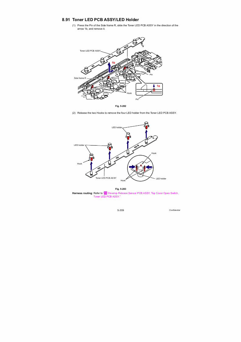
7/18/2019 Brother Mfc 9125cn 9325cw en 5694 Mfp Sm
http://slidepdf.com/reader/full/brother-mfc-9125cn-9325cw-en-5694-mfp-sm 436/597
5-209 Confidential
8.91 Toner LED PCB ASSY/LED Holder
(1) Press the Pin of the Side frame R, slide the Toner LED PCB ASSY in the direction of the
arrow 1b, and remove it.
Fig. 5-282
(2) Release the two Hooks to remove the four LED holder from the Toner LED PCB ASSY.
Fig. 5-283
Harness routing: Refer to “ Develop Release Sensor PCB ASSY, Top Cover Open Switch,Toner LED PCB ASSY.”
Side frame R
Pin
Toner LED PCB ASSY
Hook
Pin
1a
1b
LED holder
Hook
Toner LED PCB ASSY
LED holder
Hook
HookLED holder
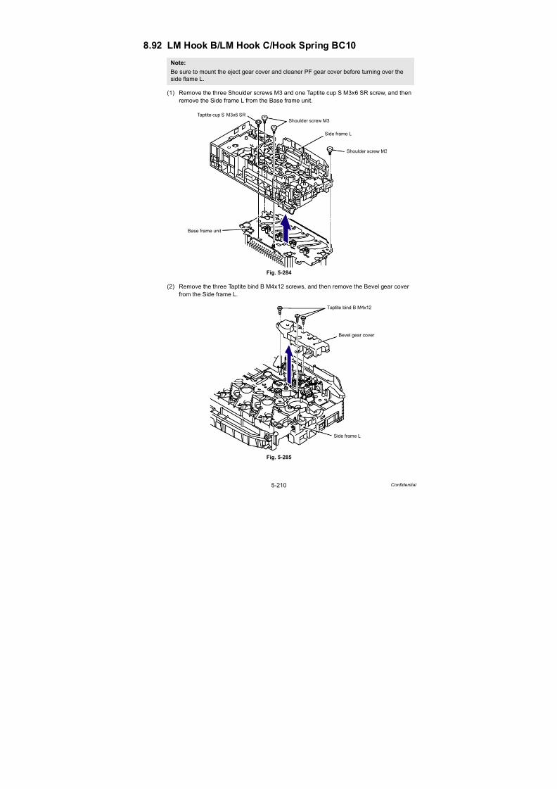
7/18/2019 Brother Mfc 9125cn 9325cw en 5694 Mfp Sm
http://slidepdf.com/reader/full/brother-mfc-9125cn-9325cw-en-5694-mfp-sm 437/597
5-210 Confidential
8.92 LM Hook B/LM Hook C/Hook Spring BC10
(1) Remove the three Shoulder screws M3 and one Taptite cup S M3x6 SR screw, and then
remove the Side frame L from the Base frame unit.
Fig. 5-284
(2) Remove the three Taptite bind B M4x12 screws, and then remove the Bevel gear cover
from the Side frame L.
Fig. 5-285
Note:
Be sure to mount the eject gear cover and cleaner PF gear cover before turning over the
side flame L.
Side frame L
Shoulder screw M3
Taptite cup S M3x6 SR
Shoulder screw M3
Base frame unit
Bevel gear cover
Taptite bind B M4x12
Side frame L

7/18/2019 Brother Mfc 9125cn 9325cw en 5694 Mfp Sm
http://slidepdf.com/reader/full/brother-mfc-9125cn-9325cw-en-5694-mfp-sm 438/597
5-211 Confidential
(3) Remove the LM hook B and LM hook C from the Side frame L.
Fig. 5-286
(4) Remove the Hook spring BC10 from the LM hook B and the LM hook C.
Fig. 5-287
Side frame L
LM hook B
LM hook C
LM hook B
Hook
Hook
LM hook C
Hook spring BC10
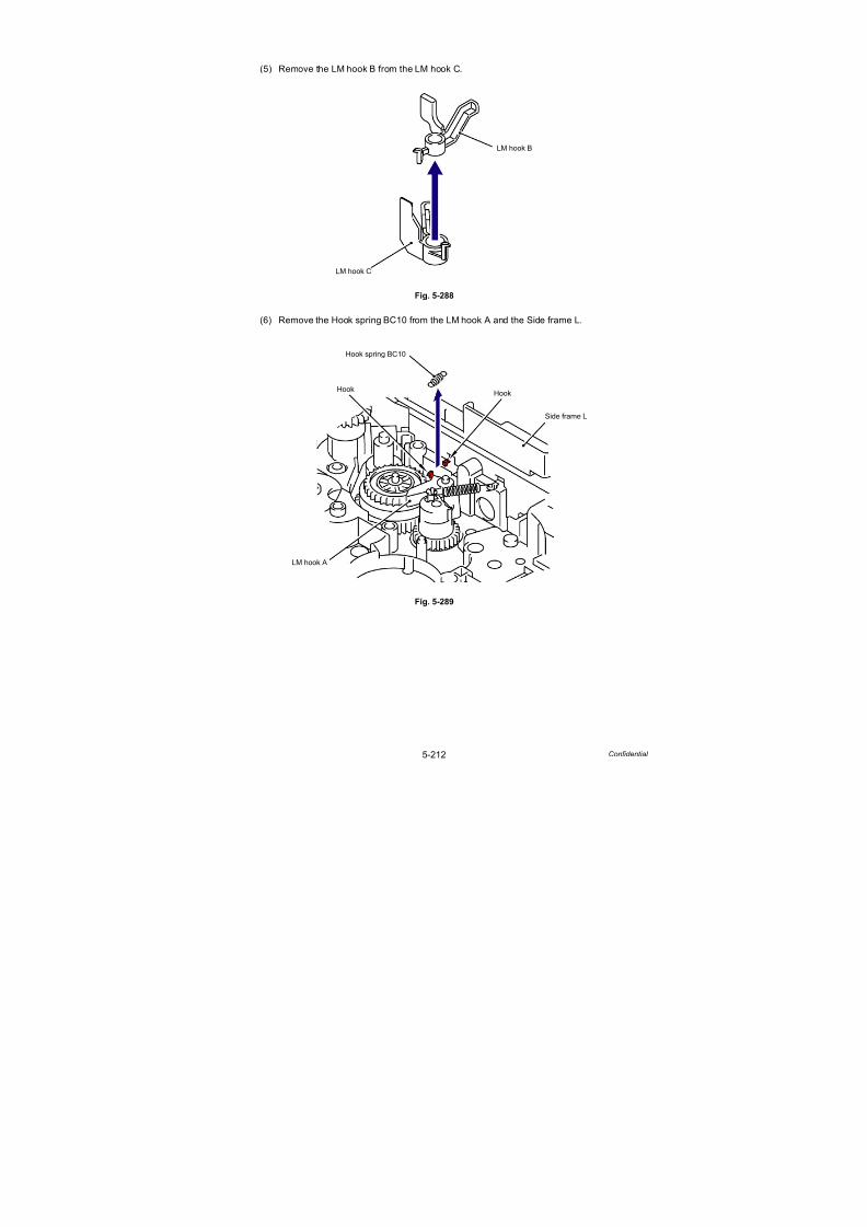
7/18/2019 Brother Mfc 9125cn 9325cw en 5694 Mfp Sm
http://slidepdf.com/reader/full/brother-mfc-9125cn-9325cw-en-5694-mfp-sm 439/597
5-212 Confidential
(5) Remove the LM hook B from the LM hook C.
Fig. 5-288
(6) Remove the Hook spring BC10 from the LM hook A and the Side frame L.
Fig. 5-289
LM hook B
LM hook C
LM hook A
Hook spring BC10
Side frame L
HookHook

7/18/2019 Brother Mfc 9125cn 9325cw en 5694 Mfp Sm
http://slidepdf.com/reader/full/brother-mfc-9125cn-9325cw-en-5694-mfp-sm 440/597
Confidential
CHAPTER 6ADJUSTMENTS AND UPDATING OF SETTINGS,
REQUIRED AFTER PARTS REPLACEMENT

7/18/2019 Brother Mfc 9125cn 9325cw en 5694 Mfp Sm
http://slidepdf.com/reader/full/brother-mfc-9125cn-9325cw-en-5694-mfp-sm 441/597
Confidential
CHAPTER 6
ADJUSTMENTS AND UPDATING OF SETTINGS,
REQUIRED AFTER PARTS REPLACEMENTThis chapter describes adjustments and updating of settings, which are required if the main PCB and
some other parts have been replaced. This chapter also covers how to update the firmware.
CONTENTS
1. IF YOU REPLACE THE MAIN PCB...........................................................6-1
1.1 Rewriting the Firmware (Main Firmware, Sub Firmware (PCL/PS)) ........................... 6-7
1.1.1 Checking firmware version ................................................................................ 6-7
1.1.2 Rewriting the firmware using computer ............................................................. 6-7
1.1.3 Rewriting the firmware using USB flash memory
(USB direct interface model only) ...................................................................... 6-9
1.2 Setting by Country (Maintenance Mode: Code 74) .................................................. 6-11
1.3 Initialization of EEPROM of Main PCB (Maintenance Mode: Code 01).................... 6-11
1.4 Setting the Serial Number ........................................................................................ 6-11
1.5 Sensitivity Adjustment of Density Sensor (Maintenance Mode: Code 72)................6-13
1.6 Performing the Developing Bias Voltage Correction(Maintenance Mode: Code 83) ................................................................................. 6-13
1.7 Performing the Adjustment of Color Registration (Maintenance Mode: Code 66).... 6-13
1.8 Acquiring MAC Address (Ethernet Address) from Wireless LAN PCB
(Wireless LAN model only) ....................................................................................... 6-13
1.9 Acquiring White Level Data (Maintenance Mode: Code 55)..................................... 6-13
1.10 Performing Operational Check of Operation Panel Buttons
(Maintenance Mode: Code 13) ................................................................................. 6-13
2. IF YOU REPLACE THE WIRELESS LAN PCB
(WIRELESS LAN MODEL ONLY) ...........................................................6-142.1 Acquiring MAC Address (Ethernet Address) from Main PCB................................... 6-14
3. IF YOU REPLACE THE REGISTRATION SENSOR HOLDER ASSY ....6-14
3.1 Sensitivity Adjustment of Density Sensor (Maintenance Mode: Code 72)................6-14
4. IF YOU REPLACE THE DOCUMENT SCANNER UNIT..........................6-14
4.1 Acquiring White Level Data and Setting CIS Scanner Area ..................................... 6-14
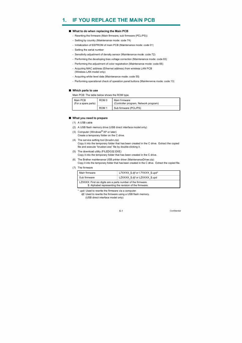
7/18/2019 Brother Mfc 9125cn 9325cw en 5694 Mfp Sm
http://slidepdf.com/reader/full/brother-mfc-9125cn-9325cw-en-5694-mfp-sm 442/597
6-1 Confidential
1. IF YOU REPLACE THE MAIN PCB
What to do when replacing the Main PCB
- Rewriting the firmware (Main firmware, sub firmware (PCL/PS))
- Setting by country (Maintenance mode: code 74)
- Initialization of EEPROM of main PCB (Maintenance mode: code 01)
- Setting the serial number
- Sensitivity adjustment of density sensor (Maintenance mode: code 72)
- Performing the developing bias voltage correction (Maintenance mode: code 83)
- Performing the adjustment of color registration (Maintenance mode: code 66)
- Acquiring MAC address (Ethernet address) from wireless LAN PCB
(Wireless LAN model only)
- Acquiring white level data (Maintenance mode: code 55)- Performing operational check of operation panel buttons (Maintenance mode: code 13)
Which parts to use
Main PCB: The table below shows the ROM type.
What you need to prepare
(1) A USB cable
(2) A USB flash memory drive (USB direct interface model only)
(3) Computer (Windows® XP or later)
Create a temporary folder on the C drive.
(4) The service setting tool (brusbn.zip)
Copy it into the temporary folder that has been created in the C drive. Extract the copied
file and execute “brusbsn.exe” file by double-clicking it.
(5) The download utility (FILEDG32.EXE)
Copy it into the temporary folder that has been created in the C drive.
(6) The Brother maintenance USB printer driver (MaintenanceDriver.zip)
Copy it into the temporary folder that has been created in the C drive. Extract the copied file.
(7) The firmware
* upd: Used to rewrite the firmware via a computer.
djf: Used to rewrite the firmware using a USB flash memory.(USB direct interface model only)
Main PCB(For a spare parts)
ROM 0 Main firmware(Controller program, Network program)
ROM 1 Sub firmware (PCL/PS)
Main firmware LZXXXX_$.djf or LZXXXX_$.upd*
Sub firmware LZXXXX_$.djf or LZXXXX_$.upd
LZXXXX: First six digits are a parts number of the firmware.$: Alphabet representing the revision of the firmware.
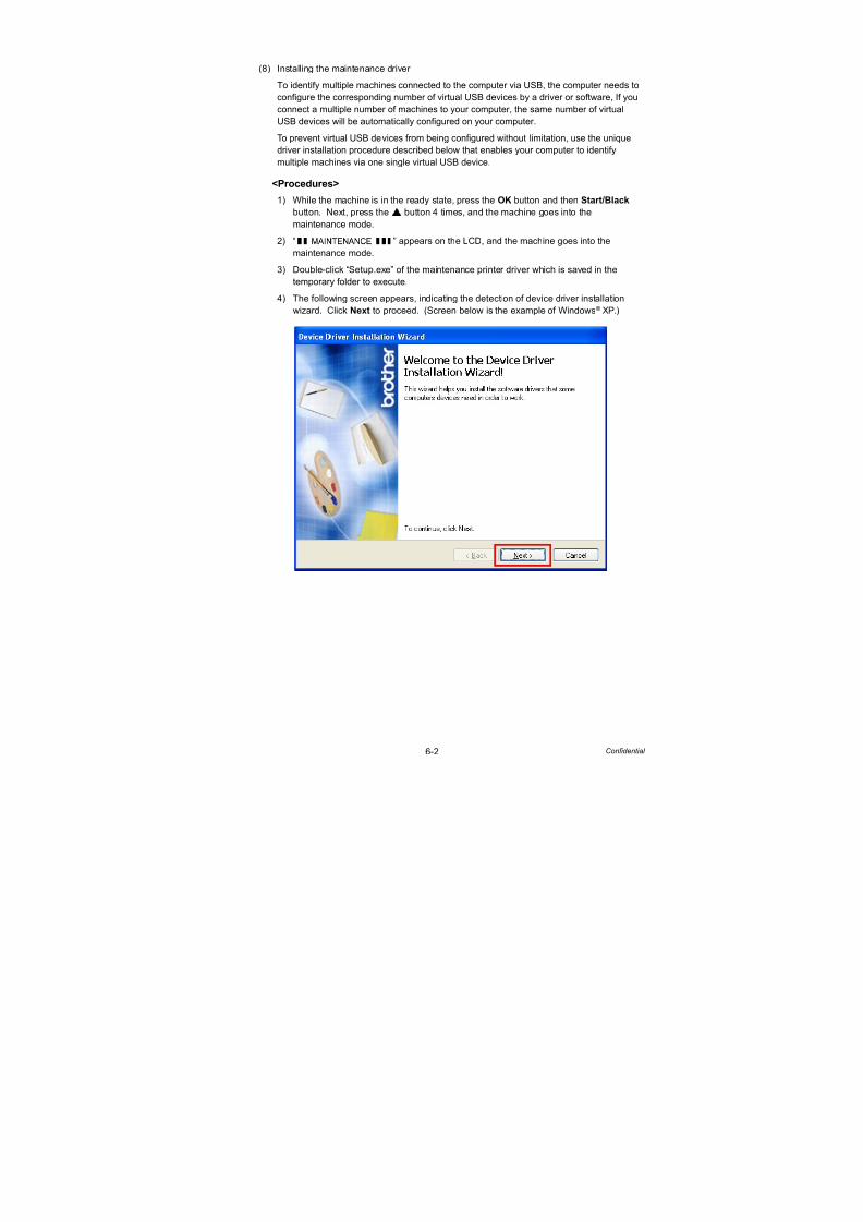
7/18/2019 Brother Mfc 9125cn 9325cw en 5694 Mfp Sm
http://slidepdf.com/reader/full/brother-mfc-9125cn-9325cw-en-5694-mfp-sm 443/597
6-2 Confidential
(8) Installing the maintenance driver
To identify multiple machines connected to the computer via USB, the computer needs to
configure the corresponding number of virtual USB devices by a driver or software, If you
connect a multiple number of machines to your computer, the same number of virtual
USB devices will be automatically configured on your computer.
To prevent virtual USB devices from being configured without limitation, use the uniquedriver installation procedure described below that enables your computer to identify
multiple machines via one single virtual USB device.
<Procedures>
1) While the machine is in the ready state, press the OK button and then Start/Black
button. Next, press the button 4 times, and the machine goes into the
maintenance mode.
2) “ ” appears on the LCD, and the machine goes into the
maintenance mode.
3) Double-click “Setup.exe” of the maintenance printer driver which is saved in the
temporary folder to execute.
4) The following screen appears, indicating the detection of device driver installation
wizard. Click Next to proceed. (Screen below is the example of Windows® XP.)
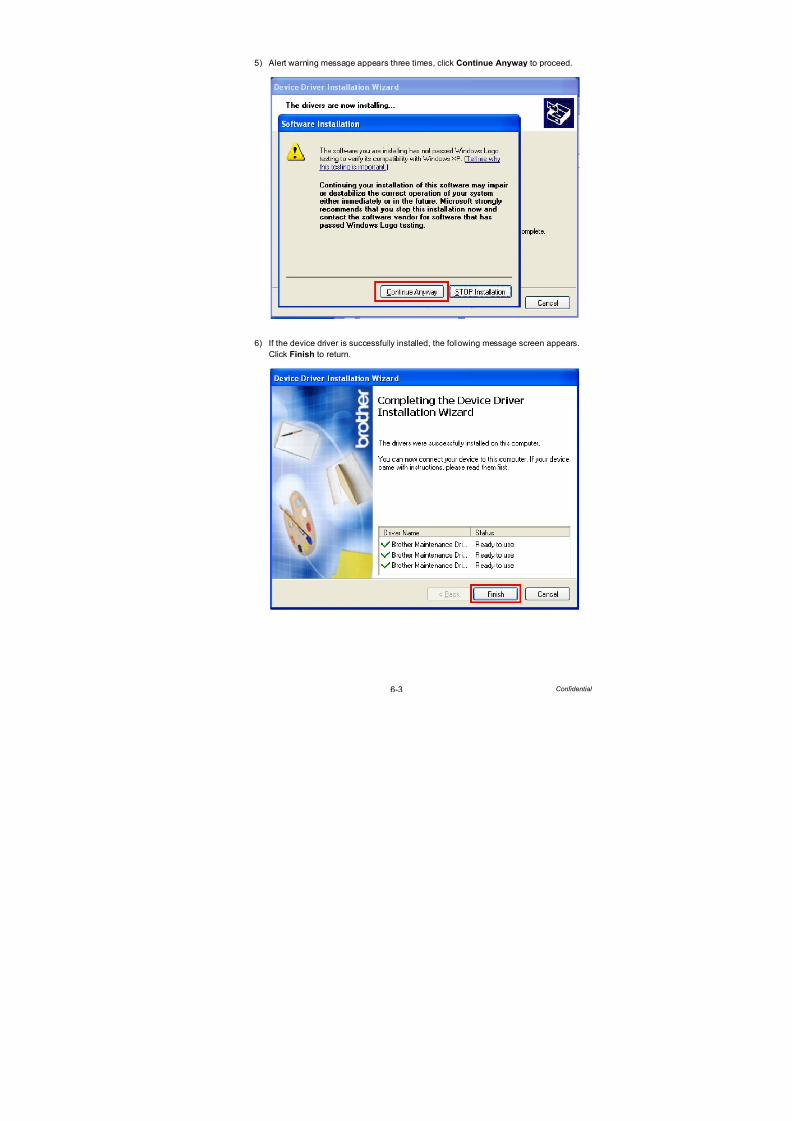
7/18/2019 Brother Mfc 9125cn 9325cw en 5694 Mfp Sm
http://slidepdf.com/reader/full/brother-mfc-9125cn-9325cw-en-5694-mfp-sm 444/597
6-3 Confidential
5) Alert warning message appears three times, click Continue Anyway to proceed.
6) If the device driver is successfully installed, the following message screen appears.
Click Finish to return.
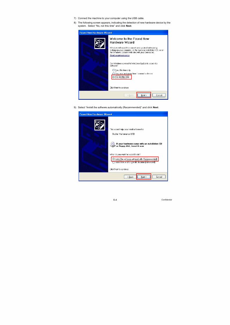
7/18/2019 Brother Mfc 9125cn 9325cw en 5694 Mfp Sm
http://slidepdf.com/reader/full/brother-mfc-9125cn-9325cw-en-5694-mfp-sm 445/597
6-4 Confidential
7) Connect the machine to your computer using the USB cable.
8) The following screen appears, indicating the detection of new hardware device by the
system. Select “No, not this time” and click Next.
9) Select “Install the software automatically (Recommended)” and click Next.
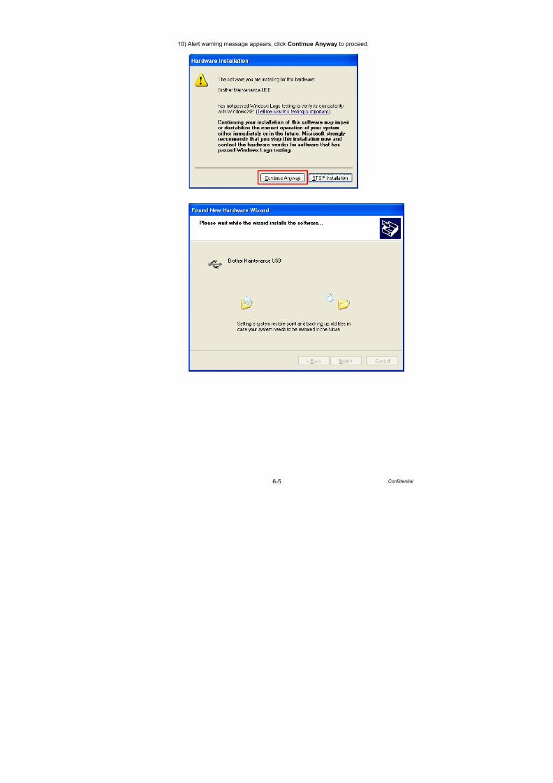
7/18/2019 Brother Mfc 9125cn 9325cw en 5694 Mfp Sm
http://slidepdf.com/reader/full/brother-mfc-9125cn-9325cw-en-5694-mfp-sm 446/597
6-5 Confidential
10) Alert warning message appears, click Continue Anyway to proceed.

7/18/2019 Brother Mfc 9125cn 9325cw en 5694 Mfp Sm
http://slidepdf.com/reader/full/brother-mfc-9125cn-9325cw-en-5694-mfp-sm 447/597
6-6 Confidential
11) If the Brother maintenance USB printer driver is successfully installed, the following
message screen appears. Click Finish to return.
12) Repeat the steps from 9) to 11) three times, and then complete its installation.
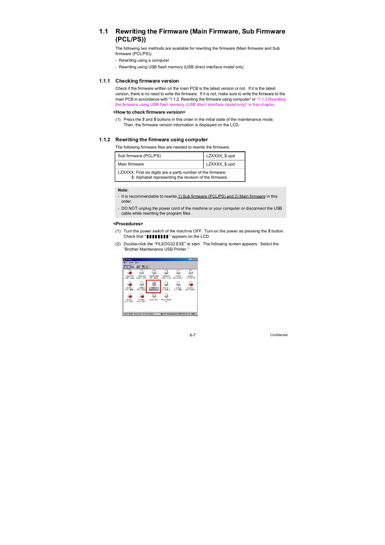
7/18/2019 Brother Mfc 9125cn 9325cw en 5694 Mfp Sm
http://slidepdf.com/reader/full/brother-mfc-9125cn-9325cw-en-5694-mfp-sm 448/597
6-7 Confidential
1.1 Rewriting the Firmware (Main Firmware, Sub Firmware
(PCL/PS))
The following two methods are available for rewriting the firmware (Main firmware and Sub
firmware (PCL/PS)).
- Rewriting using a computer - Rewriting using USB flash memory (USB direct interface model only)
1.1.1 Checking firmware version
Check if the firmware written on the main PCB is the latest version or not. If it is the latest
version, there is no need to write the firmware. If it is not, make sure to write the firmware to the
main PCB in accordance with “1.1.2. Rewriting the firmware using computer” or “1.1.3 Rewriting
the firmware using USB flash memory (USB direct interface model only)” in this chapter .
<How to check firmware version>
(1) Press the 2 and 5 buttons in this order in the initial state of the maintenance mode.
Then, the firmware version information is displayed on the LCD.
1.1.2 Rewriting the firmware using computer
The following firmware files are needed to rewrite the firmware.
<Procedures>
(1) Turn the power switch of the machine OFF. Turn on the power as pressing the 5 button.
Check that “ ” appears on the LCD.
(2) Double-click the “FILEDG32.EXE” to start. The following screen appears. Select the“Brother Maintenance USB Printer.”
Sub firmware (PCL/PS) LZXXXX_$.upd
Main firmware LZXXXX_$.upd
LZXXXX: First six digits are a parts number of the firmware.$: Alphabet representing the revision of the firmware.
Note:
- It is recommendable to rewrite 1) Sub firmware (PCL/PS) and 2) Main firmware in thisorder.
- DO NOT unplug the power cord of the machine or your computer or disconnect the USBcable while rewriting the program files.

7/18/2019 Brother Mfc 9125cn 9325cw en 5694 Mfp Sm
http://slidepdf.com/reader/full/brother-mfc-9125cn-9325cw-en-5694-mfp-sm 449/597
6-8 Confidential
(3) Click the “Brother Maintenance USB Printer” icon to select. Drag the necessary firmware
program file such as LZXXXX_$.upd and drop it.
(4) Upon completion of rewriting, the machine restarts and returns to the ready state
automatically.
Note:
After rewriting Sub firmware (PCL/PS) or Main firmware is completed, the machine returnsto the ready state. When you write a program file continuously, turn OFF the power of the
machine, and then turn it on again as pressing the 5 button. Check that “ ”appears on the LCD.

7/18/2019 Brother Mfc 9125cn 9325cw en 5694 Mfp Sm
http://slidepdf.com/reader/full/brother-mfc-9125cn-9325cw-en-5694-mfp-sm 450/597
6-9 Confidential
1.1.3 Rewriting the firmware using USB flash memory(USB direct interface model only)
If you save the program files in the USB flash memory drive and plug it into the USB direct
interface, you can rewrite the firmware.
When a USB flash memory is used, the following firmware files are needed to rewrite the
firmware.
<Procedures>
(1) Save the program files (such as LZXXXX_$.djf) which are necessary for rewriting the
firmware that are prepared in the temporary folder to the USB flash memory.
(2) While the machine is in the ready state, connect the USB flash memory drive to the USB
direct interface on the front of the machine.
Fig. 6-1
(3) When the machine recognizes the USB flash memory, the names of the files stored in the
USB flash memory are displayed. Select an appropriate file using the or button,
and then press the OK button.
Sub firmware (PCL/PS) LZXXXX_$.djf
Main firmware LZXXXX_$.djf
LZXXXX: First six digits are a parts number of the firmware.$: Alphabet representing the revision of the firmware.
Note:
- Make sure that the USB flash memory drive has enough space to save the program file.
- It is recommendable to rewrite 1) Sub firmware (PCL/PS) and 2) Main firmware in this
order.- If rewriting the firmware using a USB flash memory fails and an error message appears
on the LCD, or no message appears on the LCD, it will be necessary to rewrite thefirmware from a computer using the “FILEDG32.EXE.” (Refer to “1.1.2 Rewriting thefirmware using computer” in this chapter .)
Memo:
To print and check the list of data stored in the USB flash memory, display the LCD,
select “Index Print” using the or button, and then press the OK button.

7/18/2019 Brother Mfc 9125cn 9325cw en 5694 Mfp Sm
http://slidepdf.com/reader/full/brother-mfc-9125cn-9325cw-en-5694-mfp-sm 451/597
6-10 Confidential
(4) “Program Update/Press Start” appears on the LCD. Press the Start/Black or OK button
to start. “Program Updating/Do not turn OFF” message appears on the LCD with Data
LED blinking while rewriting the firmware. DO NOT turn OFF the machine.
(5) When the rewrite is finished, the machine automatically restarts.
(6) If you continue to rewrite other firmware and no file names are displayed, wait for a while,
and take out the USB flash memory and insert it again. When file names are displayed,select the program files which need to be rewritten, and repeat the above procedures (3)
to (5) to rewrite all the selected program files.
(7) When the rewrite of the main firmware is finished, the machine automatically restarts.
(8) Remove the USB flash memory drive from the USB direct interface once the update have
finished.
(9) Next, make the settings according to the country. (Refer to “1.4.23 Setting by country
(Function code 74)” in Chapter 7)
Memo:
You can check the firmware version of the Main firmware and the Sub firmware (PCL/PS)on the display of the machine’s log (Function code 80). (Refer to “1.2.27 Display of themachine’s log” in Chapter 7.)

7/18/2019 Brother Mfc 9125cn 9325cw en 5694 Mfp Sm
http://slidepdf.com/reader/full/brother-mfc-9125cn-9325cw-en-5694-mfp-sm 452/597
6-11 Confidential
1.2 Setting by Country (Maintenance Mode: Code 74)Make appropriate settings by country in accordance with “1.4.23 Setting by country” in Chapter 7.
1.3 Initialization of EEPROM of Main PCB (MaintenanceMode: Code 01)Initialize the EEPROM in accordance with “1.4.1 EEPROM parameter initialization” in Chapter 7.
1.4 Setting the Serial Number
<Procedures>
(1) Connect the PC and machine with the USB cable.
(2) Double-click the brusbsn.exe file which has been copied in the temporary folder to start.
(3) Click the C-Laser 10Model.
(4) In Port on the brusbsn screen, select the port number assigned to the BrotherMaintenance USB Printer. If the port number is unknown, follow steps below.
1) Click Start | Settings | Printers.
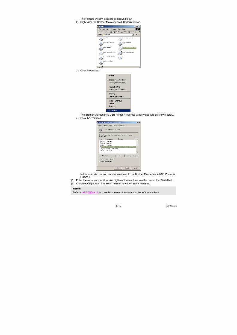
7/18/2019 Brother Mfc 9125cn 9325cw en 5694 Mfp Sm
http://slidepdf.com/reader/full/brother-mfc-9125cn-9325cw-en-5694-mfp-sm 453/597
6-12 Confidential
The Printers window appears as shown below.
2) Right-click the Brother Maintenance USB Printer icon.
3) Click Properties.
The Brother Maintenance USB Printer Properties window appears as shown below.
4) Click the Ports tab.
In this example, the port number assigned to the Brother Maintenance USB Printer is
USB001.(5) Enter the serial number (the nine digits) of the machine into the box on the “Serial No”.
(6) Click the [OK] button. The serial number is written in the machine.
Memo:Refer to APPENDIX. 3 to know how to read the serial number of the machine.

7/18/2019 Brother Mfc 9125cn 9325cw en 5694 Mfp Sm
http://slidepdf.com/reader/full/brother-mfc-9125cn-9325cw-en-5694-mfp-sm 454/597
6-13 Confidential
1.5 Sensitivity Adjustment of Density Sensor
(Maintenance Mode: Code 72)
Make sensitivity adjustments of the density sensor in accordance with “1.4.22 Sensitivity
adjustment of density sensor” in Chapter 7.
1.6 Performing the Developing Bias Voltage Correction
(Maintenance Mode: Code 83)
Perform developing bias voltage correction in accordance with “1.4.29 Developing bias voltage
correction” in Chapter 7.
1.7 Performing the Adjustment of Color Registration
(Maintenance Mode: Code 66)
Perform adjustment of color registration in accordance with “1.4.17 Adjustment of color
registration” in Chapter 7.
1.8 Acquiring MAC Address (Ethernet Address) from
Wireless LAN PCB (Wireless LAN model only)
<Procedures>
(1) Turn ON the power as holding down the button and OK button at the same time.
Keep holding down the button and OK button until “Check start” appears.(2) When the MAC address (Ethernet address) is acquired from the wireless LAN PCB, “W
Lan Module OK” is displayed on the LCD.
(3) Turn OFF the power.
1.9 Acquiring White Level Data (Maintenance Mode:
Code 55)
Acquire the white level data in accordance with “1.4.16 Acquiring white level data” in Chapter 7.
1.10 Performing Operational Check of Operation Panel
Buttons (Maintenance Mode: Code 13)
Perform the operational check for the operation panel in accordance with “1.4.8 Operational
check of control panel button” in Chapter 7.

7/18/2019 Brother Mfc 9125cn 9325cw en 5694 Mfp Sm
http://slidepdf.com/reader/full/brother-mfc-9125cn-9325cw-en-5694-mfp-sm 455/597
6-14 Confidential
2. IF YOU REPLACE THE WIRELESS LAN
PCB (WIRELESS LAN MODEL ONLY)
What to do when replacing the wireless LAN PCB
Acquiring MAC Address (Ethernet Address) from Main PCB
2.1 Acquiring MAC Address (Ethernet Address) from Main PCB
<Procedures>
(1) Turn ON the power as holding down the button and OK button at the same time.
Keep holding down the button and OK button until “Check start” appears.
(2) When the MAC address (Ethernet address) is acquired from the main PCB, “W Lan
Module OK” is displayed on the LCD.
(3) Turn OFF the power.
3. IF YOU REPLACE THE REGISTRATION
SENSOR HOLDER ASSY
What to do when replacing the registration sensor holder ASSY
Sensitivity Adjustment of Density Sensor (Maintenance Mode: Code 72)
3.1 Sensitivity Adjustment of Density Sensor
(Maintenance Mode: Code 72)Make adjustments of the density sensor in accordance with “1.4.22 Sensitivity adjustment of
density sensor” in Chapter 7.
4. IF YOU REPLACE THE DOCUMENT
SCANNER UNIT
What to do when replacing the document scanner unit
Acquisition of the white level data and setting of the CIS scanner area
4.1 Acquiring White Level Data and Setting CIS Scanner Area
<Procedure>
(1) Press the Menu button and Start/Black button in this order, and then press the button
four times to go into the maintenance mode. (Refer to “1.1 How to Enter Maintenance
Mode” in Chapter 7.)
(2) Press the 5 button twice.
(3) Press the Start/Black button. The white level data is automatically acquired.
(4) When the acquisition is completed, the machine automatically returns to the initial state ofthe maintenance mode.

7/18/2019 Brother Mfc 9125cn 9325cw en 5694 Mfp Sm
http://slidepdf.com/reader/full/brother-mfc-9125cn-9325cw-en-5694-mfp-sm 456/597
Confidential
CHAPTER 7SERVICE FUNCTIONS
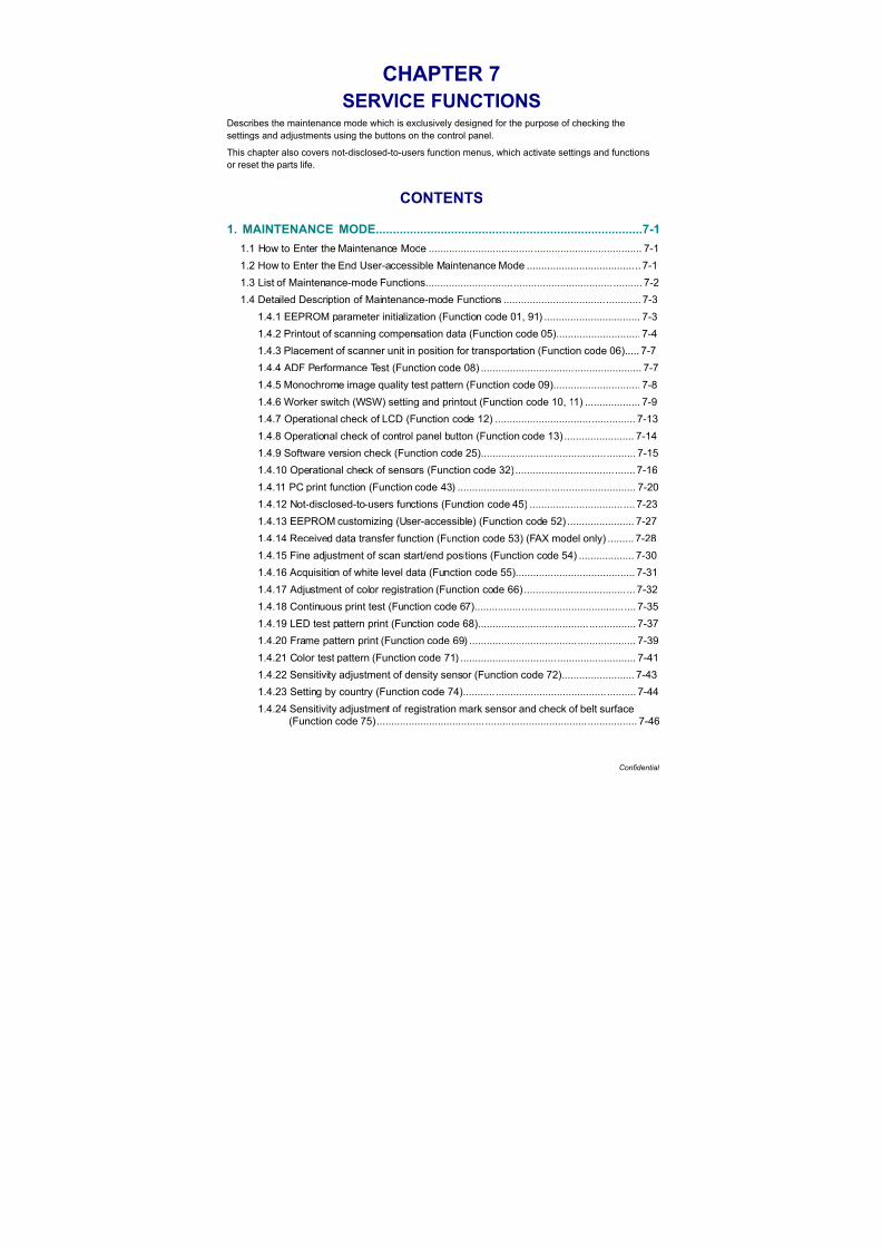
7/18/2019 Brother Mfc 9125cn 9325cw en 5694 Mfp Sm
http://slidepdf.com/reader/full/brother-mfc-9125cn-9325cw-en-5694-mfp-sm 457/597
Confidential
CHAPTER 7
SERVICE FUNCTIONS
Describes the maintenance mode which is exclusively designed for the purpose of checking the
settings and adjustments using the buttons on the control panel.This chapter also covers not-disclosed-to-users function menus, which activate settings and functions
or reset the parts life.
CONTENTS
1. MAINTENANCE MODE..............................................................................7-1
1.1 How to Enter the Maintenance Mode ......................................................................... 7-1
1.2 How to Enter the End User-accessible Maintenance Mode ....................................... 7-1
1.3 List of Maintenance-mode Functions.......................................................................... 7-2
1.4 Detailed Description of Maintenance-mode Functions ............................................... 7-3
1.4.1 EEPROM parameter initialization (Function code 01, 91) ................................. 7-3
1.4.2 Printout of scanning compensation data (Function code 05)............................. 7-4
1.4.3 Placement of scanner unit in position for transportation (Function code 06)..... 7-7
1.4.4 ADF Performance Test (Function code 08) ....................................................... 7-7
1.4.5 Monochrome image quality test pattern (Function code 09).............................. 7-8
1.4.6 Worker switch (WSW) setting and printout (Function code 10, 11) ................... 7-9
1.4.7 Operational check of LCD (Function code 12) ................................................ 7-131.4.8 Operational check of control panel button (Function code 13) ........................ 7-14
1.4.9 Software version check (Function code 25)..................................................... 7-15
1.4.10 Operational check of sensors (Function code 32)......................................... 7-16
1.4.11 PC print function (Function code 43) ............................................................. 7-20
1.4.12 Not-disclosed-to-users functions (Function code 45) .................................... 7-23
1.4.13 EEPROM customizing (User-accessible) (Function code 52) ....................... 7-27
1.4.14 Received data transfer function (Function code 53) (FAX model only) ......... 7-28
1.4.15 Fine adjustment of scan start/end positions (Function code 54) ................... 7-30
1.4.16 Acquisition of white level data (Function code 55)......................................... 7-31
1.4.17 Adjustment of color registration (Function code 66) ...................................... 7-32
1.4.18 Continuous print test (Function code 67)....................................................... 7-35
1.4.19 LED test pattern print (Function code 68)...................................................... 7-37
1.4.20 Frame pattern print (Function code 69) ......................................................... 7-39
1.4.21 Color test pattern (Function code 71) ............................................................ 7-41
1.4.22 Sensitivity adjustment of density sensor (Function code 72)......................... 7-43
1.4.23 Setting by country (Function code 74)........................................................... 7-44
1.4.24 Sensitivity adjustment of registration mark sensor and check of belt surface(Function code 75)......................................................................................... 7-46

7/18/2019 Brother Mfc 9125cn 9325cw en 5694 Mfp Sm
http://slidepdf.com/reader/full/brother-mfc-9125cn-9325cw-en-5694-mfp-sm 458/597
Confidential
1.4.25 Printout of maintenance information (Function code 77)............................... 7-48
1.4.26 Operational check of fans (Function code 78)............................................... 7-49
1.4.27 Display of the machine’s log (Function code 80) ........................................... 7-50
1.4.28 Error code indication (Function code 82)....................................................... 7-53
1.4.29 Developing bias voltage correction (Function code 83)................................. 7-541.4.30 Output of transmission log to the telephone line (Function code 87) ............ 7-55
1.4.31 Counter reset after replacing the fuser unit and paper feeding kit(Function code 88)......................................................................................... 7-55
1.4.32 Exit from maintenance mode (Function code 99).......................................... 7-55
2. OTHER SERVICE FUNCTIONS...............................................................7-56
2.1 Resetting the Periodical Maintenance Parts Life...................................................... 7-56
2.1.1 Resetting the life counter of the belt unit ......................................................... 7-56
2.1.2 Resetting the life counter of the fuser unit ....................................................... 7-562.1.3 Resetting the life counter of the drum unit....................................................... 7-57
2.1.4 Resetting the life counter of the paper feeding kit ........................................... 7-57
2.2 Develop Roller Counter Reset Function ................................................................... 7-58
2.3 How to Recover from Errors of the Fuser Unit ......................................................... 7-59

7/18/2019 Brother Mfc 9125cn 9325cw en 5694 Mfp Sm
http://slidepdf.com/reader/full/brother-mfc-9125cn-9325cw-en-5694-mfp-sm 459/597
7-1 Confidential
1. MAINTENANCE MODE
The maintenance mode is exclusively designed for the checking, setting and adjustments of
the machine by using the buttons on the control panel cover ASSY. The EEPROM can be
customized according to the destination of the machine. Moreover, the operational check of
the LCD, operation panel board, and sensors, print test, display of the log information and
error codes, and change of the worker switches (WSW) can be performed.
1.1 How to Enter the Maintenance Mode
<Operating procedure>
(1) Press the Menu button and then the Start/Black button while the machine is in the ready
state. Next, press the button four times to enter the maintenance mode.
(2) The machine beeps for one second and displays “ ” on the LCD,
indicating that it is placed in the initial state of the maintenance mode, a mode in which the
machine is ready to accept entry from the buttons.
(3) To select any of the maintenance mode functions shown in the next page, enter the
maintenance mode that you want to use using the buttons.
1.2 How to Enter the End User-accessible Maintenance Mode
Basically, the maintenance-mode functions listed in the next page should be accessed by
service personnel only. However, you can allow end users to access some of these under the
guidance of service personnel by phone, for example.
The end user-accessible functions are shaded in the table given on the next page. (codes 06,
09, 10, 11, 12, 25, 43, 52, 53, 54, 68, 71, 72, 77, 80, 82, 87, 88 and 91)Function code 10 accesses the firmware switches, each of which has eight selectors. You
should not allow end users to access all of those selectors, but you can allow them to access
user-accessible selectors which are shaded in the firmware switch tables in APPENDIX 1.
The service personnel should instruct end users to follow the procedure given below.
<Operating procedure>
(1) Press the Menu, Start/Black, Menu and buttons in this order when the machine is in
the ready state. “MAINTENANCE 06” appears on the LCD.
(2) Press the or button to display the desired maintenance code on the LCD. Then
press the OK button.
To switch the machine back to the ready state, press the Stop/Exit button. When each of the
user-accessible functions is completed, the machine automatically returns to the ready state.
Memo:
FAX models equipped with numerical keypads can enter the maintenance mode in the
same way as conventional models; that is, by pressing the Menu, *, 2, 8, 6 and 4
buttons in this sequence.
Memo:
- To exit from the maintenance mode and switch to ready state, press the 9 button twice in
the initial state of the maintenance mode.
- When the Stop/Exit button is pressed, the machine beeps for one second and returns tothe initial state of the maintenance mode.
- When an incorrect maintenance mode is entered, the machine beeps for one second and
returns to the initial state of the maintenance mode.

7/18/2019 Brother Mfc 9125cn 9325cw en 5694 Mfp Sm
http://slidepdf.com/reader/full/brother-mfc-9125cn-9325cw-en-5694-mfp-sm 460/597
7-2 Confidential
1.3 List of Maintenance-mode Functions
* The functions shaded in the table above are user-accessible.
Functioncode
Function Refer to:
01 EEPROM parameter initialization 1.4.1 (7-3)
05 Printout of scanning compensation data 1.4.2 (7-4)
06 Placement of scanner module position for transportation 1.4.3 (7-7)
08 ADF performance test 1.4.4 (7-7)
09 Monochrome image quality test pattern 1.4.5 (7-8)
10 Worker switch (WSW) setting 1.4.6 [1] (7-9)
11 Printout of worker switch (WSW) data 1.4.6 [2] (7-12)
12 Operational check of LCD 1.4.7 (7-13)
13 Operational check of control panel button 1.4.8 (7-14)
25 Software version check 1.4.9 (7-15)32 Operational check of sensors 1.4.10 (7-16)
43 PC print function 1.4.11 (7-20)
45 Not-disclosed-to-users functions 1.4.12 (7-23)
52 EEPROM customizing (User-accessible) 1.4.13 (7-27)
53 Received data transfer function 1.4.14 (7-28)
54 Fine adjustment of scan start/end positions 1.4.15 (7-30)
55 Acquisition of white level data 1.4.16 (7-31)
66 Adjustment of color registration 1.4.17 (7-32)
67 Continuous print test 1.4.18 (7-35)
68 LED test pattern print 1.4.19 (7-37)
69 Frame pattern print 1.4.20 (7-39)
71 Color test pattern 1.4.21 (7-41)
72 Sensitivity adjustment of density sensor 1.4.22 (7-43)
74 Setting by country 1.4.23 (7-44)
75 Sensitivity adjustment of registration mark sensor andcheck of belt surface
1.4.24 (7-46)
77 Printout of maintenance information 1.4.25 (7-48)
78 Operational check of fans 1.4.26 (7-49)80 Display of the machine’s log 1.4.27 (7-50)
82 Error code indication 1.4.28 (7-53)
83 Developing bias voltage correction 1.4.29 (7-54)
87 Output of transmission log to the telephone line 1.4.30 (7-55)
88 Counter reset after replacing the fuser unit and paper feeding kit
1.4.31 (7-55)
91 EEPROM parameter Initialization 1.4.1 (7-3)
99 Exit from the maintenance mode 1.4.32 (7-55)
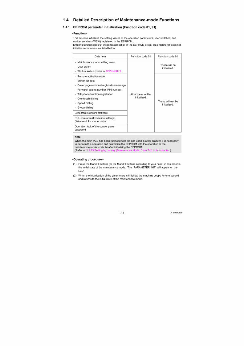
7/18/2019 Brother Mfc 9125cn 9325cw en 5694 Mfp Sm
http://slidepdf.com/reader/full/brother-mfc-9125cn-9325cw-en-5694-mfp-sm 461/597
7-3 Confidential
1.4 Detailed Description of Maintenance-mode Functions
1.4.1 EEPROM parameter initialization (Function code 01, 91)
<Function>
This function initializes the setting values of the operation parameters, user switches, andworker switches (WSW) registered in the EEPROM.
Entering function code 01 initializes almost all of the EEPROM areas, but entering 91 does not
initialize some areas, as listed below.
<Operating procedure>
(1) Press the 0 and 1 buttons (or the 9 and 1 buttons according to your need) in this order in
the initial state of the maintenance mode. The “PARAMETER INIT” will appear on the
LCD.
(2) When the initialization of the parameters is finished, the machine beeps for one second
and returns to the initial state of the maintenance mode.
Data item Function code 01 Function code 91
- Maintenance mode setting value
- User switch
- Worker switch (Refer to APPENDIX 1.)
All of these will be
initialized.
These will be
initialized.
- Remote activation code
- Station ID data
- Cover page comment registration message
- Forward/ paging number, PIN number
- Telephone function registration
- One-touch dialing
- Speed dialing
- Group dialing
These will not be
initialized.
LAN area (Network settings)
PCL core area (Emulation settings)
(Wireless LAN model only)
Operation lock of the control panel
password
Note:
When the main PCB has been replaced with the one used in other product, it is necessary
to perform this operation and customize the EEPROM with the operation of the
maintenance mode: code 74 after initializing the EEPROM.
(Refer to “1.4.23 Setting by country (Maintenance Mode: Code 74)” in this chapter .)

7/18/2019 Brother Mfc 9125cn 9325cw en 5694 Mfp Sm
http://slidepdf.com/reader/full/brother-mfc-9125cn-9325cw-en-5694-mfp-sm 462/597
7-4 Confidential
1.4.2 Printout of scanning compensation data (Function code 05)
<Function>
The machine prints out the white and black level data for scanning compensation.
<Operating procedure>
(1) For white and black scanning, copy the document. For color scanning, implement color
copy of the document.
(2) Press the 0 and 5 buttons in this order in the initial state of the maintenance mode.
The “PRINTING” will appear on the LCD.
(3) The equipment prints out the scanning compensation data list (Refer to Fig. 7-1 and Fig.
7-2) containing the following:
Black and white scanning
Color scanning
Note:
- Implement the operating procedure below after scanning the document once at least, not
immediately after the machine is turned on. Since the machine initializes the white and
black level data and obtains the standard value for document scanning compensation
when starting scanning the document, the correct data for compensation cannot be
printed out even if this operation is implemented without scanning the document.
- The print result varies depending on whether implementing color scanning or black and
white scanning immediately before this operating procedure. Make sure the white and
black level data you want to print and implement the operation below.
a) Black and white data graph
b) LED PWM data 1 byte
c) LED pulse data (G) 2 bytes
d) RLCV (AFE parameter) 1 bytee) OFFSET (AFE parameter) 1 byte
f) GAIN (AFE parameter) 2 bytes
g) Background color compensated data 1 byte
h) Black level data by previous scanning pixel count
i) White level data (G) by previous scanning pixel count
j) White level data (B) by previous scanning pixel count
k) White level data (R) by previous scanning pixel count
a) Black and white data graph
b) LED PWM data 1 byte
c) LED pulse data (G) 2 bytes
d) LED pulse data (B) 2 bytes
e) LED pulse data (R) 2 bytes
f) RLCV (AFE parameter) 1 byte
g) OFFSET (AFE parameter) 1 byte
h) GAIN (AFE parameter) 2 bytes
i) Background color compensated data 1 byte
j) Black level data by previous scanning pixel count
k) White level data (G) by previous scanning pixel count
l) White level data (B) by previous scanning pixel countm) White level data (R) by previous scanning pixel count

7/18/2019 Brother Mfc 9125cn 9325cw en 5694 Mfp Sm
http://slidepdf.com/reader/full/brother-mfc-9125cn-9325cw-en-5694-mfp-sm 463/597
7-5 Confidential
(4) When printing of the correction data is finished, the machine beeps for one second and
returns to the initial state of the maintenance mode.
For white and black scanning
Fig. 7-1
Note:
- If any data is abnormal, its code will be printed in inline style.
- Regarding the black and white level data after monochrome reading is done, only the G
data is printed, and R and B data are not printed.
- The white level data and black level data are imported in 10/16 bits, and the data in the
upper 8 bits are printed.
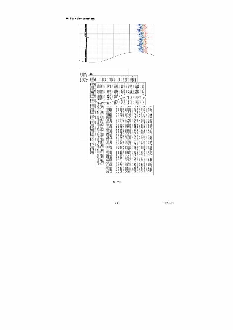
7/18/2019 Brother Mfc 9125cn 9325cw en 5694 Mfp Sm
http://slidepdf.com/reader/full/brother-mfc-9125cn-9325cw-en-5694-mfp-sm 464/597
7-6 Confidential
For color scanning
Fig. 7-2

7/18/2019 Brother Mfc 9125cn 9325cw en 5694 Mfp Sm
http://slidepdf.com/reader/full/brother-mfc-9125cn-9325cw-en-5694-mfp-sm 465/597
7-7 Confidential
1.4.3 Placement of scanner unit in position for transportation (Function code 06)
<Function>
This function is to move the scanner unit in position for transportation located at the left end.
When you fix the machine and check its operation, you need to perform this function last
before packing and shipping.
<Operating procedure>
(1) Press the 0 and 6 buttons in this order in the initial state of the maintenance mode.
The scanner unit moves to the designated position for transportation located at the left
end. The “MAINTENANCE 06” is displayed until the scanner unit is placed in position.
When the document scanner unit is placed in the position, the “SCAN LOCKED” appears
on the LCD.
(2) When the Stop/Exit button is pressed, the machine beeps for one second and returns to
the initial state of the maintenance mode.
1.4.4 ADF Performance Test (Function code 08)
<Function>
The machine counts the documents fed by the automatic document feeder (ADF) and displays
the count on the LCD for checking the ADF performance.
<Operating procedure>
(1) Set documents. (Allowable up to the ADF capacity.)
The “DOC. READY” will appear on the LCD.
(2) Press the 0 and 8 buttons in this order. While counting the documents, the machine feeds
them in and out, displaying the current count on the LCD as shown below.
(3) When the Stop/Exit button is pressed, the machine cancels this operation, beeps for one
second and returns to the initial state of the maintenance mode.
Note:
Please instruct end users to perform this function if possible before packing and shipping
their FAX machine to a sales agent or a service dealer for the purpose of repair.
(For information on the procedure to make the user operate the maintenance mode, refer to
“1.2 How to Enter the End User-accessible Maintenance Mode” in this chapter .)
Note:
- When the document scanner unit fails to move to the transport position or when the
maintenance mode: code 06 is executed while a reading error occurs, “SCAN LOCK
ERROR” appears.
- After the scanner unit has moved to the transport position, the reading operations such as
copy cannot be performed.
Current count (1st page in this example)

7/18/2019 Brother Mfc 9125cn 9325cw en 5694 Mfp Sm
http://slidepdf.com/reader/full/brother-mfc-9125cn-9325cw-en-5694-mfp-sm 466/597
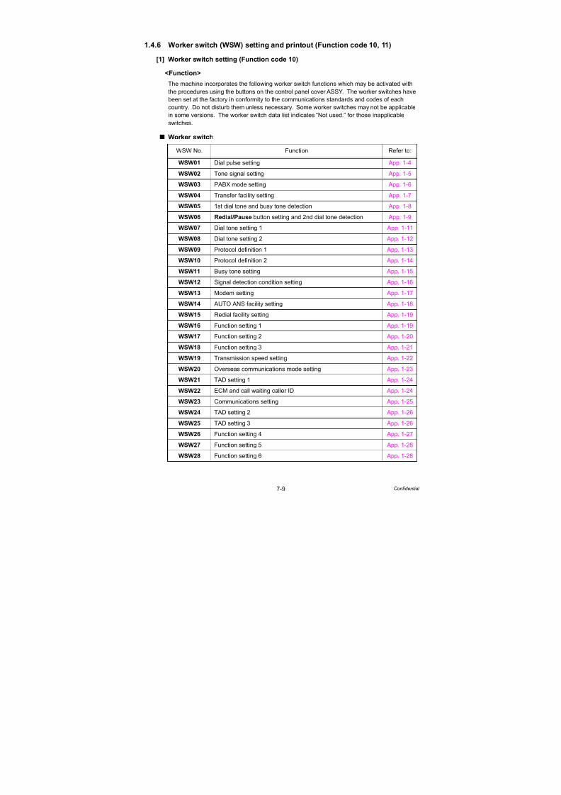
7/18/2019 Brother Mfc 9125cn 9325cw en 5694 Mfp Sm
http://slidepdf.com/reader/full/brother-mfc-9125cn-9325cw-en-5694-mfp-sm 467/597
7-9 Confidential
1.4.6 Worker switch (WSW) setting and printout (Function code 10, 11)
[1] Worker switch setting (Function code 10)
<Function>
The machine incorporates the following worker switch functions which may be activated with
the procedures using the buttons on the control panel cover ASSY. The worker switches have
been set at the factory in conformity to the communications standards and codes of each
country. Do not disturb them unless necessary. Some worker switches may not be applicable
in some versions. The worker switch data list indicates “Not used.” for those inapplicable
switches.
Worker switch
WSW No. Function Refer to:
WSW01 Dial pulse setting App. 1-4
WSW02 Tone signal setting App. 1-5
WSW03 PABX mode setting App. 1-6
WSW04 Transfer facility setting App. 1-7
WSW05 1st dial tone and busy tone detection App. 1-8
WSW06 Redial/Pause button setting and 2nd dial tone detection App. 1-9
WSW07 Dial tone setting 1 App. 1-11
WSW08 Dial tone setting 2 App. 1-12
WSW09 Protocol definition 1 App. 1-13
WSW10 Protocol definition 2 App. 1-14
WSW11 Busy tone setting App. 1-15
WSW12 Signal detection condition setting App. 1-16
WSW13 Modem setting App. 1-17
WSW14 AUTO ANS facility setting App. 1-18
WSW15 Redial facility setting App. 1-19
WSW16 Function setting 1 App. 1-19
WSW17 Function setting 2 App. 1-20
WSW18 Function setting 3 App. 1-21
WSW19 Transmission speed setting App. 1-22
WSW20 Overseas communications mode setting App. 1-23
WSW21 TAD setting 1 App. 1-24
WSW22 ECM and call waiting caller ID App. 1-24
WSW23 Communications setting App. 1-25
WSW24 TAD setting 2 App. 1-26
WSW25 TAD setting 3 App. 1-26
WSW26 Function setting 4 App. 1-27
WSW27 Function setting 5 App. 1-28WSW28 Function setting 6 App. 1-28

7/18/2019 Brother Mfc 9125cn 9325cw en 5694 Mfp Sm
http://slidepdf.com/reader/full/brother-mfc-9125cn-9325cw-en-5694-mfp-sm 468/597
7-10 Confidential
WSW29 Function setting 7 App. 1-29
WSW30 Function setting 8 App. 1-29
WSW31 Function setting 9 App. 1-30
WSW32 Function setting 10 App. 1-30
WSW33 Function setting 11 App. 1-31
WSW34 Function setting 12 App. 1-31
WSW35 Function setting 13 App. 1-31
WSW36 Function setting 14 App. 1-32
WSW37 Function setting 15 App. 1-33
WSW38 V.34 transmission settings App. 1-34
WSW39 V.34 transmission speed App. 1-35
WSW40 V.34 modem settings App. 1-36
WSW41 ON-duration of the scanning light source App. 1-37
WSW42 Internet mail settings App. 1-37
WSW43 Function setting 21 App. 1-38
WSW44 Speeding up scanning-1 App. 1-38
WSW45 Speeding up scanning-2 App. 1-39
WSW46 Monitor of power ON/OFF state and parallel port kept at high App. 1-40
WSW47 Switching between high- and full-speed USB App. 1-41
WSW48 USB setup latency App. 1-41WSW49 End-of-copying beep and print in black App. 1-42
WSW50 SDAA settings App. 1-42
WSW51 Function setting 16 App. 1-43
WSW52 Function setting 17 App. 1-43
WSW53 Function setting 18 App. 1-43
WSW54 Function setting 19 App. 1-44
WSW55 Interval of time requred for the developing bias voltage correction App. 1-45
WSW56 Function setting 21 App. 1-45
WSW57 Function setting 22 App. 1-46
WSW58 Function setting 23 App. 1-46
WSW59 Function setting 24 App. 1-47
WSW60 Function setting 25 App. 1-48
WSW61 Scanning light intensity to judge to be stable 1 App. 1-49
WSW62 Scanning light intensity to judge to be stable 2 App. 1-49
WSW63 Function setting 26 App. 1-50
WSW64 Setting the language/Default paper size App. 1-51
WSW65 Setting the paper support App. 1-51
WSW No. Function Refer to:

7/18/2019 Brother Mfc 9125cn 9325cw en 5694 Mfp Sm
http://slidepdf.com/reader/full/brother-mfc-9125cn-9325cw-en-5694-mfp-sm 469/597
7-11 Confidential
<Operating procedure>
(1) Press the 1 and 0 buttons in this order in the initial state of the maintenance mode.
The machine displays “WSW00” on the LCD and becomes ready to accept a worker
switch number.
(2) Enter the desired number from the worker switch numbers (01 through 76).
The following appears on the LCD.
(3) Enter a value to be set (0 or 1) using the 0 and 1 buttons.
(4) Press the OK button. This operation saves the newly entered selector values onto the
EEPROM and readies the machine for accepting a worker switch number.
(5) Repeat steps (2) through (4) until the modification for the desired worker switches is completed.
(6) When the Stop/Exit button is pressed, the machine beeps for one second and returns to
the initial state of the maintenance mode.
WSW66 Reserved (Change of the setting is prohibited) App. 1-52
WSW67 Reserved (Change of the setting is prohibited) App. 1-52
WSW68 Reserved (Change of the setting is prohibited) App. 1-52
WSW69 Reserved (Change of the setting is prohibited) App. 1-52
WSW70 Reserved (Change of the setting is prohibited) App. 1-52
WSW71 Reserved (Change of the setting is prohibited) App. 1-52
WSW72 Reserved (Change of the setting is prohibited) App. 1-53
WSW73 Reserved (Change of the setting is prohibited) App. 1-53
WSW74 ADF stop control App. 1-53
WSW75 Paper feeding parameter for turning the document counter
when the machine takes action duplex scanning
App. 1-53
WSW76 The limited number of the documents in reverse for paperejection of the simplex scanning from ADF App. 1-54
WSW77 The limited number of the documents in reverse for paper
ejection of the duplex scanning from ADF
App. 1-54
Memo:
- To cancel this operation and return to the machine to the initial state of the maintenance
mode during the above procedure, press the Stop/Exit button.
- If there is a pause of more than one minute after a single-digit number is entered for
double-digit worker switch numbers, the machine will automatically return to the initial
state of the maintenance mode.
WSW No. Function Refer to:
Selector 1 Selector 8
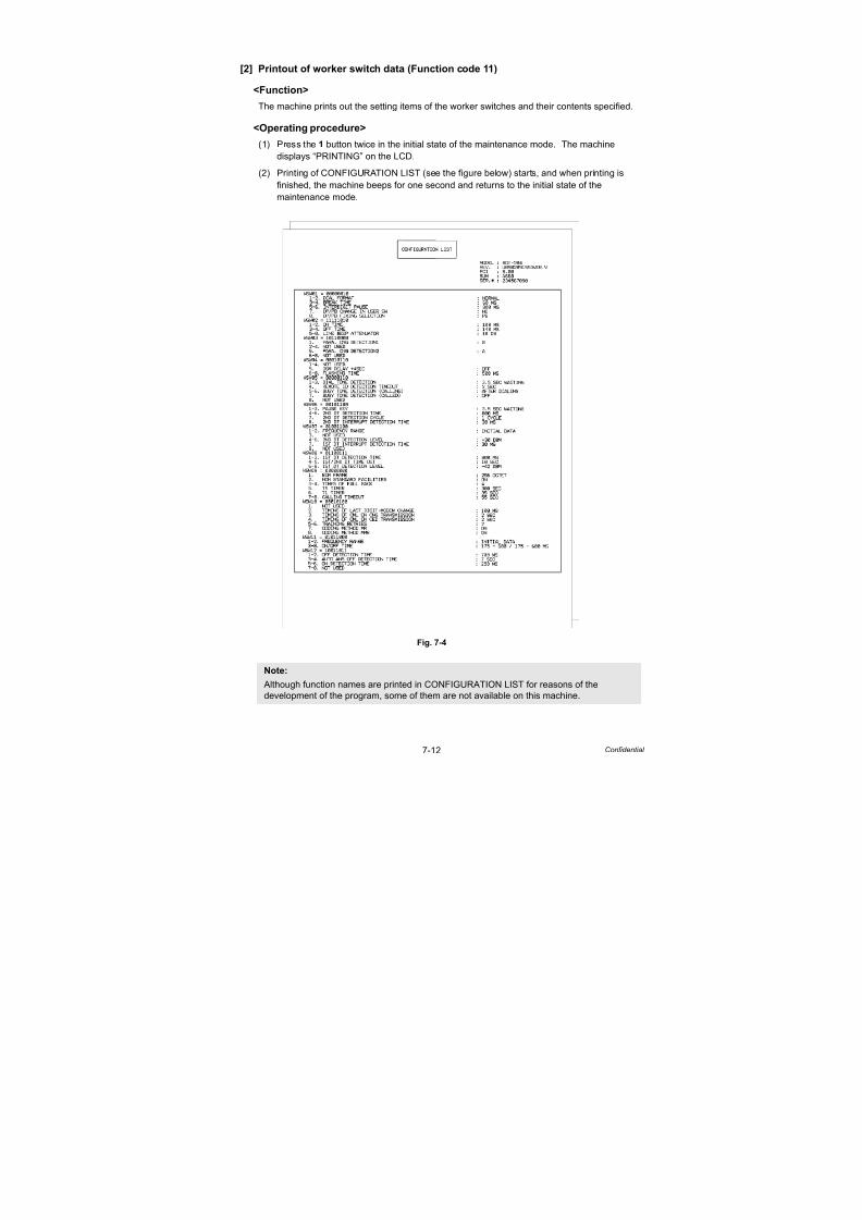
7/18/2019 Brother Mfc 9125cn 9325cw en 5694 Mfp Sm
http://slidepdf.com/reader/full/brother-mfc-9125cn-9325cw-en-5694-mfp-sm 470/597
7-12 Confidential
[2] Printout of worker switch data (Function code 11)
<Function>
The machine prints out the setting items of the worker switches and their contents specified.
<Operating procedure>
(1) Press the 1 button twice in the initial state of the maintenance mode. The machine
displays “PRINTING” on the LCD.
(2) Printing of CONFIGURATION LIST (see the figure below) starts, and when printing is
finished, the machine beeps for one second and returns to the initial state of the
maintenance mode.
Fig. 7-4
Note:
Although function names are printed in CONFIGURATION LIST for reasons of thedevelopment of the program, some of them are not available on this machine.

7/18/2019 Brother Mfc 9125cn 9325cw en 5694 Mfp Sm
http://slidepdf.com/reader/full/brother-mfc-9125cn-9325cw-en-5694-mfp-sm 471/597
7-13 Confidential
1.4.7 Operational check of LCD (Function code 12)
<Function>
This function allows you to check whether the LCD on the control panel cover ASSY works
normally.
<Operating procedure>
(1) Press the 1 and 2 buttons in this order in the initial state of the maintenance mode.
The LCD shows.
(2) Each time you press the Start/Black button, the LCD cycles through the displays as
shown below.
(3) When the Stop/Exit button is pressed regardless of the display, the machine cancels the
operation, beeps for one second and returns to the initial state of the maintenance mode.
<Display 1>
Backlight
LCDData LED
Error LED
: OFF
: Display of all dots: Green blinking
: Red blinking
<Display 2>
Backlight
LCD
Data LED
Error LED
: OFF
: Display of a frame with
2 lines and 16 dots
: Green blinking
: Red blinking
<Display 3>
Backlight
LCDData LED
Error LED
: OFF
: Display of no dots: Green blinking
: Red blinking
<Display 4>
Backlight
LCD
Data LED
Error LED
: ON
: Display of no dots
: Green blinking
: Red blinking
Fig. 7-5
Display 1
Display 2
Display 3
Display 4

7/18/2019 Brother Mfc 9125cn 9325cw en 5694 Mfp Sm
http://slidepdf.com/reader/full/brother-mfc-9125cn-9325cw-en-5694-mfp-sm 472/597
7-14 Confidential
1.4.8 Operational check of control panel button (Function code 13)
<Function>
This function allows you to check if the buttons on the control panel cover ASSY work properly.
<Operating procedure>
(1) Press the 1 and 3 buttons in this order in the initial state of the maintenance mode.
The “00” will appear on the LCD.
(2) Press the buttons in the order designated in the illustration shown below.
The LCD shows the corresponding number in decimal notation each time a button is
pressed. Check that the displayed number is correct by referring to the illustration below.
When the buttons are pressed in an incorrect order, a warning beep goes off and
“INVALID OPERATE” appears on the LCD at the same time. Press the Stop/Exit button,
and the press the correct buttons.
(3) After the last number button is pressed, the machine beeps for one second and returns to
the initial state of the maintenance mode.
MFC-9120CN/9125CN/9320CW/9325CW
Fig. 7-6
DCP-9010CN/MFC-9010CN
Fig. 7-7
Memo:
When the Stop/Exit button is pressed during the operation, the machine beeps for one
second and returns to the initial state of the maintenance mode.

7/18/2019 Brother Mfc 9125cn 9325cw en 5694 Mfp Sm
http://slidepdf.com/reader/full/brother-mfc-9125cn-9325cw-en-5694-mfp-sm 473/597
7-15 Confidential
1.4.9 Software version check (Function code 25)
<Function>
This function allows you to check the management information of the software programs such
as version information, check sum.
<Operating procedure>
(1) Press the 2 and 5 buttons in this order in the initial state of the maintenance mode. The
machine displays each of items described below on the LCD.
(2) Press the or button to check the next item.
(3) When the Stop/Exit button is pressed, the machine cancels this operation, beeps for one
second, and returns to the initial state of the maintenance mode.
*1 How to display the check sum information
Press the OK button when its version information is displayed on the LCD to display
the check sum information. Press the OK button again to go back to the version
information display. Press the or button to check the next item.
*2 There are two types of check sum information which can be checked with this function.
This function checks if these two types of check sum information are matched each
other. When you press the OK button while “ROM Check Sum” is displayed, check is
automatically conducted for each ROM of each software part. When the check sum is
matched, “OK” is displayed on the LCD. When all ROMs result in OK, “ROM Check
Sum OK” is displayed at the end, and the operation is finished.
When the check sum of any ROM is not matched, NG is displayed, and the display
stops.
LCD Description
TOTAL: Ver A*1 Main firmware version information
(A): Revision informationPCL: Ver 1.00*1 Sub firmware (PCL/PS) version information
ENG: Ver1.00*1 Engine firmware version information
NET: Ver 1.00 Network program version information
PICT: Ver 1.00 PictBridge version information
HV: Ver 1.00 High voltage CPU program version and PCB information
i0801170900:0000 I-FAX firmware version information
B09014151027:AF57*1 Boot program creation date
U09040911553:A668*1 Main firmware creation date
D09041191021:2E8F*1 Demo firmware data creation date
P09040031122:FC00*1 Sub firmware (PCL/PS) creation date
ROM Check Sum Check sum self-diagnosis function*2
Note:
Regarding the version information (Engine, Network, PictBridge, and HVPS) ofwhich check sum information cannot be obtained, the check sum information is not
displayed even if you press the OK button.

7/18/2019 Brother Mfc 9125cn 9325cw en 5694 Mfp Sm
http://slidepdf.com/reader/full/brother-mfc-9125cn-9325cw-en-5694-mfp-sm 474/597
7-16 Confidential
1.4.10 Operational check of sensors (Function code 32)
<Function>
This function allows you to check each of the sensors.
<Operational procedure>
(1) Press the 3 and 2 buttons in this order in the initial state of the maintenance mode.
(2) The machine beeps 1,100 Hz and 400 Hz tones cyclically through the following volumes
for testing the speaker. To stop beeping, press the OK button.
Fig. 7-8
The operation condition of the sensor becomes the one defined in the table below, and
“P1MPCVRCRMRAPOFW” is displayed on the LCD. When the Start/Black button is
pressed, the selected item is switched to the next item.
Given below is the relationship between the LCD indication, sensor name and sensor state.
LCD Sensors Sensing status (OK/NG)
P1 Paper eject rear sensor Paper not detected/detected
MP Manual sensor Paper not detected/detected
CV Top cover sensor Top cover closed/open
RC Back cover sensor Back cover closed/openRM Registration front sensor Paper not detected/detected
RA Registration rear sensor Paper not detected/detected
PO Paper eject front sensor Paper not detected/detected
FW Waste toner sensor Toner full/not detected
NK New toner sensor K Used toner/New toner
NY New toner sensor Y Used toner/New toner
NM New toner sensor M Used toner/New toner
NC New toner sensor C Used toner/New toner
KC Toner sensor K Toner (K) detected/not detected
YC Toner sensor Y Toner (Y) detected/not detected
MC Toner sensor M Toner (M) detected/not detected
CC Toner sensor C Toner (C) detected/not detected
Note:
- The operating noise is generated when the new toner sensor K and new toner sensor
Y are operated while the cover is open.
- The “--” appears on the LCD if there is no display.
- The “**” appears on the LCD if the parts are not installed or there is no item.
OFF
400 HzLow Medium High
1,100 HzHigh Medium Low
OFF

7/18/2019 Brother Mfc 9125cn 9325cw en 5694 Mfp Sm
http://slidepdf.com/reader/full/brother-mfc-9125cn-9325cw-en-5694-mfp-sm 475/597
7-17 Confidential
(3) Check that the display on the LCD is changed when the detection condition of each
sensor is changed.
For instance, insert paper to the document front (rear) sensor or the registration front
(rear) sensor, open the top cover or the back cover, take out the toner cartridge, make a
jam at the paper outlet, and insert paper from the manual feed slot, etc.
(4) When the Stop/Exit button is pressed, the machine beeps for one second and returns to
the initial state of the maintenance mode.
LCD SensorsSensing status
(OK/NG of temperature/humidity)
TMP External temperature sensor XX °C/NG
HUM External humidity sensor XX %/NG
MAC temperature sensor XX °C/NG
BT Belt thermistor XX °C/NG
LCD Sensors Sensing status (OK/NG)
DF Document front sensor Without documents/With document
DR Document rear sensor Without documents/With document
AC ADF cover open sensor Close/Open
FH FB unit home position sensor Home position/Not home position
Note:
- The “--” appears on the LCD if there is no display.
- The “**” appears on the LCD if the parts are not installed or there is no item.

7/18/2019 Brother Mfc 9125cn 9325cw en 5694 Mfp Sm
http://slidepdf.com/reader/full/brother-mfc-9125cn-9325cw-en-5694-mfp-sm 476/597
7-18 Confidential
Location of sensors
Fig. 7-9
Fig. 7-10
Manual sensor
Registration front
Registration rear sensor
Waste toner sensor
New toner sensor K
New toner sensor Y
New toner sensor M
New toner sensor C
Toner sensor K
Toner sensor Y
Toner sensor M
Toner sensor C
Paper feed unit
Registration front/rear sensor PCB ASSY
Waste toner
sensor
sensor holder
<Front>
Paper eject rear sensor
Back cover
Paper eject frontsensor
sensorTop cover sensor
External temperature/
humidity sensor
Belt thermistor
Internal temperature
<Front>
Paper eject guide ASSY
sensor
Registration sensorholder ASSY
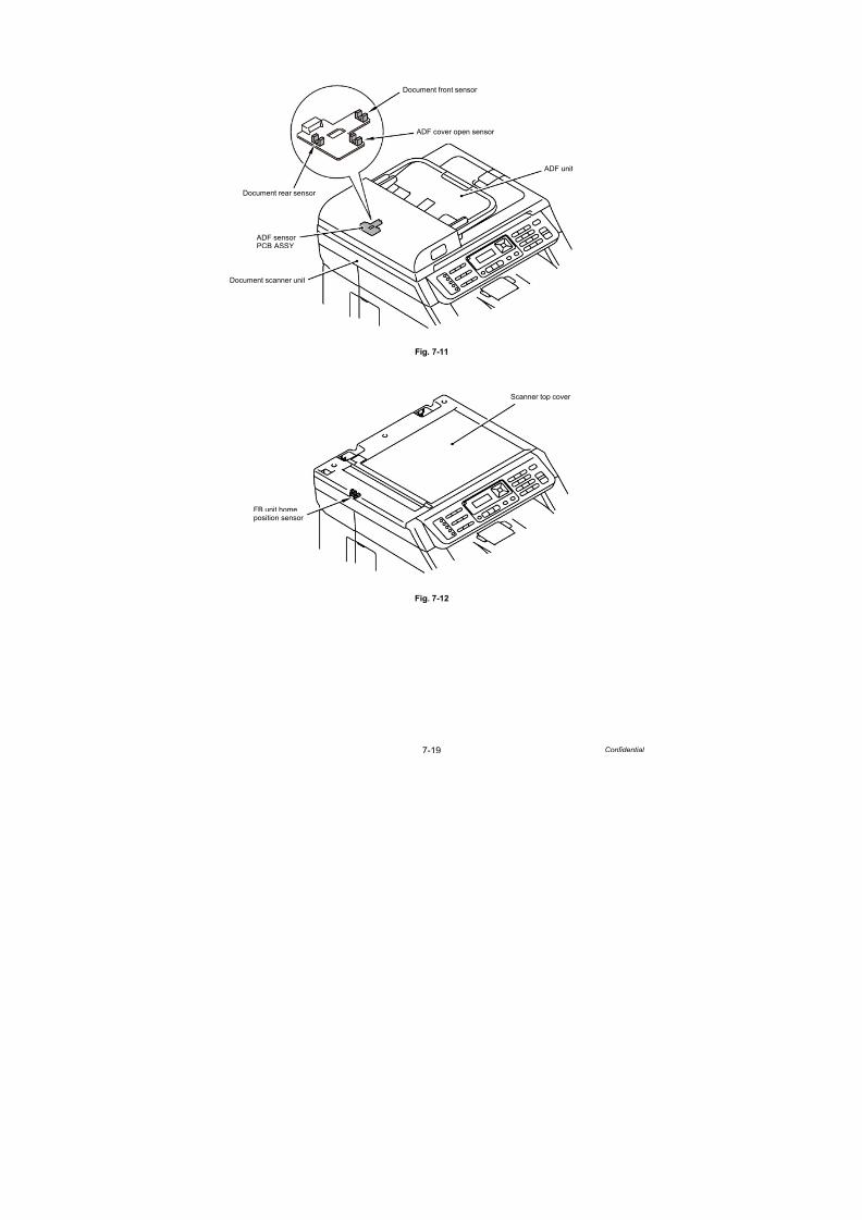
7/18/2019 Brother Mfc 9125cn 9325cw en 5694 Mfp Sm
http://slidepdf.com/reader/full/brother-mfc-9125cn-9325cw-en-5694-mfp-sm 477/597
7-19 Confidential
Fig. 7-11
Fig. 7-12
Document front sensor
Document rear sensor
ADF cover open sensor
ADF unit
Document scanner unit
ADF sensorPCB ASSY
Scanner top cover
FB unit homeposition sensor

7/18/2019 Brother Mfc 9125cn 9325cw en 5694 Mfp Sm
http://slidepdf.com/reader/full/brother-mfc-9125cn-9325cw-en-5694-mfp-sm 478/597
7-20 Confidential
1.4.11 PC print function (Function code 43)
<Function>
This function allows the machine change that the setting of each computer printing function
indicated to the following function settings.
<Operating procedure>
(1) Press the 4 and 3 buttons in this order in the initial state of the maintenance mode. The
“Manual Feed” will appear on the LCD.
(2) Press the or button to select the function you want to set and press the OK button.
(3) When select the unchanging (On/Off) parameter, press the or button, or change
the parameter using the numeric buttons. And press the OK button.
(4) Press the Stop/Exit button so that the machine beeps for one second and returns to the
initial state of the maintenance mode.
Function setting
LCD indication Description Set value Initial value
Manual Feed Switching of the Manual Feed On/Off Off
Resolution Resolution to print 300/600/1200 dpi 600
Toner Save Switching of the Toner Save On/Off Off
Density Switching of the Density level -6 to 6 0
JB-Can Time Setting of the time until the host
time-out at the Job Cancel
2 to 225 (seconds) 4
Sleep Time Setting of the time until enter
the Sleep Mode
0 to 99 (minutes) 5
Page
Protection
Switching of the protection of
the page memory
Off/Letter/A4/Legal/Auto Off
Emulation Switching of the emulation Auto/HP/PS Auto
Auto I/F Time Switching of the I/F open time 1 to 99 (seconds) 5
Media Type Switching of the recording
paper type
Thin/Plain/Thick/Thicker/
Trancparency/Recycled/
Bond/Envlopes/EnvThin/
EnvThick
Plain
or
Thin
Paper Size Switching of the area of
develop the image
Letter/Legal/A4/
Executive/B5/JISB5/A5/B6/A6/Monarch/C5/
COM10/DL/DLL/A4Long
/PostCard/Folio
Letter
or A4
Copies Switching of the print copies 1 to 99 (pages) 1
Orientation Switching of the print direction PortLait/Landscape Portlait
P-Pos X-Offset Switching of the offset print
position of the landscape
orientation
-500 to 500 (1/300 dpi) 0
P-Pos Y-Offset Switching of the offset print
position of the portrait
orientation
-500 to 500 (1/300 dpi) 0

7/18/2019 Brother Mfc 9125cn 9325cw en 5694 Mfp Sm
http://slidepdf.com/reader/full/brother-mfc-9125cn-9325cw-en-5694-mfp-sm 479/597
7-21 Confidential
Detail description
LCD indication Description Set value Initial value
AutoFF Switching of the auto form feed On/Off Off
AutoFF Time Switching of the time-out period
of the auto feed
1 to 99 (seconds) 5
FF Surpress Switching of the FF Suppress On/Off Off
Auto LF Switching of the auto LF On/Off Off
Auto CR Switching of the auto CR On/Off Off
Auto WRAP Switching of the auto CRLF at
the print width
On/Off Off
Auto SKIP Switching of the SKIP at the
backend/tip of the recording
paper
On/Off On
Left Margin Switching of the margin at the
left end
0 to 145 (columus) 0
Right Margin Switching of the margin at the
right end
10 to 155 (columus) 80
Top Margin Switching of the margin at the
upper end
0 to 2.00 (inches) 0.5
Bottom Margin Switching of the margin at the
bottom end
0 to 2.00 (inches) 0.5
Lines Number of the text lines in the
page
5 to 128 (lines) 60
Error Print Switching of the Error Print of
the Post Script
On/Off On
LCD indication Detail description
Manual Feed Effective for the print from the computer, or for the print of the
NetWorkConfig/TestPrint/Fontlist/Configuration from the panel. When
select the tray on the computer, the setting becomes effective. And this
setting is ignored.
Resolution Effective only for the print from the computer. When set the Resolution on
the computer, the setting becomes effective. And this setting is ignored.
Toner Save Effective for all print, and change the setting of the Function Menu.However, as for the Copy, this setting becomes invalid. When set the
Toner Save or the computer, the setting becomes effective. And this
setting is ignored.
Density Effective for the print from the computer, or for the print of the
NetWorkConfig/TestPrint/FontList/Configuration from the panel. Link the
setting of the Toner Save. Judge the both setting, and decide the
density. When set the Density or the computer, the setting becomes
effective. And this setting is ignored.
JB-Can Time Configure the setting for until the host time-out at the Job Cancel.
The setting value is the second time scale.
Sleep Time Configure the setting for the time until shift to the Sleep Time. Changethe setting of the Function Menu.

7/18/2019 Brother Mfc 9125cn 9325cw en 5694 Mfp Sm
http://slidepdf.com/reader/full/brother-mfc-9125cn-9325cw-en-5694-mfp-sm 480/597
7-22 Confidential
LCD indication Detail description
Page
Protection
Configure the setting to protect the page memory, when recording in
computer. Set in the PCL-Core. There is not the influence of the
memory management problem of the MFC.
Emulation Configure the setting for the Emulation. Change the setting of theFunction Menu. When the data include the ENTER LANGUAGE, the
setting becomes effective. And this setting is ignored.
Auto I/F Time Configure the setting for the interface open time. The function is in the
PC-Print. When the PC-Scan/Remote-SetUp works on the way, the
setting becomes invalid.
Media Type Effective for the print from the computer. When set the type of the
recording paper on the computer, the setting becomes effective. And
this setting is ignored. The default value is different by the country
setting. CHN is the Thin, and others are the Plain.
Paper Size Switching of the area of develop the image. Does not set the Paper Size
of the Menu, set the drawing size of the PC-Print. When set the size of the recording paper on the computer, the setting becomes effective. And
this setting is ignored. The default value is different by the country
setting. US/CAN are the Letter, and others are the A4.
Copies Effective for the print from the computer. When set the number of the
copies on the computer, the setting becomes effective. And this setting
is ignored.
Orientation Configure the switching for the print direction. Effective for the print from
the computer.
P-Pos X-Offset Configure the setting for the offset print position of the landscape
orientation. Effective for the print from the computer. When set the
X-Offset on the computer, the setting becomes effective. And this
setting is ignored.
P-Pos Y-Offset Configure the setting for the offset print position of the portrait orienta-
tion. Effective for the print from the computer. When set the Y-Offset on
the computer, the setting becomes effective. And this setting is ignored.
AutoFF Configure the setting for the ON/OFF of the Auto Form Feed. Effective
for the print from the computer.
AutoFF Time Configure the setting for the Time Out, when the Auto Form Feed is ON.
FF Surpress Configure the setting for the skip of the blank page. Effective for the
print from the computer. The blank data in the Copy/Fax cannot be
turned ON/ OFF in this setting.
Auto LF Configure the setting for the auto line feed.
Auto CR Configure the setting for the auto Carriage Return.
Auto WRAP Configure the setting for the auto CRLF at the print width.
Auto SKIP Configure the setting for the skip at the back-end/tip of the recording
paper and add the blank space.
Left Margin Configure the setting for the column space at the left end.
Right Margin Configure the setting for the column space at the right end.
Top Margin Configure the setting for the space at the upper end.
Bottom Margin Configure the setting for the space at the bottom end.
Lines Configure the setting for the number of the lines in the PCL.
Error Print Configure the setting for the Error Print of the BR-Script 3.

7/18/2019 Brother Mfc 9125cn 9325cw en 5694 Mfp Sm
http://slidepdf.com/reader/full/brother-mfc-9125cn-9325cw-en-5694-mfp-sm 481/597
7-23 Confidential
1.4.12 Not-disclosed-to-users functions (Function code 45)
Switching of the USB transfer speed in the PictBridge mode
<Function>
This function allows you to change the USB transfer speed in the PictBridge mode. If the
digital camera which a user uses cannot be connected in the PictBridge mode, this functionmay make it possible.
An asterisk “*” appears beside the current setting.
<Operating procedure>
(1) Press the 4 and 5 buttons in this order in the initial state of the maintenance mode. “PB.USBspeed” will appear on the LCD.
(2) Press the OK button. Then, select the required function by pressing the or button
and press the Start/Black button.
(3) The machine beeps for one second and returns to the initial state of the maintenance mode.
(4) Turn the power of the machine OFF.
Changing return value of USB No.
<Function>
When the OS of the computer is Windows Vista®, and the computer is connected to a device
through USB 2.0 full speed, the OS might fail to get the serial No. of the USB device
depending on the computer and USB device. When the OS fails to get the serial No., the
return value may continue to increase every time the device is connected to the computer.
To avoid this problem, the return value of the serial No. is dropped to “0”.
An asterisk “*” appears beside the current setting.
<Operating procedure>
(1) Press the 4 and 5 buttons in this order in the initial state of the maintenance mode.
“PB.USBspeed” will appear on the LCD.
(2) Press the or button to display “USB No.” and then press the OK or Start/Black button.
(3) Press the or button to select “USB No. = ON” or “USB No. = OFF,” and then press
the OK or Start/Black button.
(4) The machine beeps for one second and returns to the initial state of the maintenance mode.
(5) Turn the power of the machine OFF.
LCD Description
PB.Speed=AUTO Adapts the speed to the capability of the USB device. (Full Speed or
High Speed) (default)
PB.Speed=FULL Fixes the speed to Full Speed. The capability of the USB device is
not depended on.
Note:
This mode is enabled when the power of the machine is turned OFF and ON.
LCD Description
USBNo. =ON Returns the serial No. of the device. (default)
USBNo. =OFF Returns “0”.
Note:
This mode is enabled when the power of the machine is turned OFF and ON.

7/18/2019 Brother Mfc 9125cn 9325cw en 5694 Mfp Sm
http://slidepdf.com/reader/full/brother-mfc-9125cn-9325cw-en-5694-mfp-sm 482/597
7-24 Confidential
Switching dither pattern
<Function>
This function is to switch the dither pattern when printed letters and/or slanted lines are not
smooth, and thin lines are rough or uneven.
An asterisk “*” appears beside the current setting.
<Operating procedure>
(1) Press the 4 and 5 buttons in this order in the initial state of the maintenance mode.“PB.USBspeed” will appear on the LCD.
(2) Press the or button to display “PS.DitherType” and then press the OK or Start/Black
button.
(3) Press the or button to select “PS.DitherType=0” or “PS.DitherType=1,” and then
press the OK or Start/Black button.
(4) The machine beeps for one second and returns to the initial state of the maintenance mode.
Switching ON/OFF of 94 mm banding measure GridBias control function
<Function>
This function is to switch ON/OFF of the control (Engine control) to make print by increasing
GridBias at the 94-mm position from the leading edge of each page in order to avoid a banding
failure.
An asterisk “*” appears beside the current setting.
<Operating procedure>
(1) Press the 4 and 5 buttons in this order in the initial state of the maintenance mode.
“PB.USBspeed” will appear on the LCD.
(2) Press the or button to display “Bd94GrdBias” and then press the OK or Start/Black
button.
(3) Press the or button to select “Bd94GrdBias=ON” or “Bd94GrdBias=OFF,,” and then
press the OK or Start/Black button.
(4) The machine beeps for one second and returns to the initial state of the maintenance mode.
LCD Description
PS.DitherType=0 Dither Pattern 0 is selected.
(A dither pattern which improves roughness of letters and slanted
lines)
PS.DitherType=1 Dither Pattern 1 is selected.
(A dither pattern which alleviates banding) (default)
LCD Description
Bd94GrdBias=ON 94 mm Banding measure GridBias control function ON (default)
Bd94GrdBias=OFF 94 mm Banding measure GridBias control function OFF

7/18/2019 Brother Mfc 9125cn 9325cw en 5694 Mfp Sm
http://slidepdf.com/reader/full/brother-mfc-9125cn-9325cw-en-5694-mfp-sm 483/597
7-25 Confidential
Switching ON/OFF of 94 mm Banding measure transfer current correction/
DCLN voltage correction
<Function>
This function is to switch ON/OFF of the transfer current correction/DCLN voltage correction
control (Engine control) to the 94-mm position from the leading edge of each page in order to
avoid a banding failure. When banding appears, switch this control as a measure.
An asterisk “*” appears beside the current setting.
<Operating procedure>
(1) Press the 4 and 5 buttons in this order in the initial state of the maintenance mode.
“PB.USBspeed” will appear on the LCD.
(2) Press the or button to display “Bd94CrctSub” and then press the OK or Start/Black
button.
(3) Press the or button to select “Bd94CrctSub=ON” or “Bd94CrctSub=OFF,” and then
press the OK or Start/Black button.
(4) The machine beeps for one second and returns to the initial state of the maintenance mode.
Switching ON/OFF of DirectPrint Color mode - Improve Gray Color
<Function>
This function is to switch ON/OFF of the print control for the gray color when other colors are
slightly blended in the gray color or the gray color is uneven upon printing.
An asterisk “*” appears beside the current setting.
<Operating procedure>
(1) Press the 4 and 5 buttons in this order in the initial state of the maintenance mode.
“PB.USBspeed” will appear on the LCD.
(2) Press the or button to display “DP.ImpGray” and then press the OK or Start/Black
button.
(3) Press the or button to select “DP.ImpGray=ON” or “DP.ImpGray=OFF,” and then
press the OK or Start/Black button.
(4) The machine beeps for one second and returns to the initial state of the maintenance mode.
LCD Description
Bd94CrctSub=ON 94 mm Banding measure transfer current correction/
DCLN voltage correction ON
Bd94CrctSub=OFF 94 mm Banding measure transfer current correction/
DCLN voltage correction OFF (default)
LCD Description
DP.ImpGray=ON DirectPrint Color mode - Improve Gray Color. (Print control for
gray color) ON (Improves the symptom that other colors are
slightly blended in the gray color.) (default)
DP.ImpGray=OFF DirectPrint Color mode - Improve Gray Color. (Print control for
gray color) OFF (Improves the unevenness of the gray color)

7/18/2019 Brother Mfc 9125cn 9325cw en 5694 Mfp Sm
http://slidepdf.com/reader/full/brother-mfc-9125cn-9325cw-en-5694-mfp-sm 484/597
7-26 Confidential
Switching of timing to execute Auto Registration (MFC-9125CN/9325CW only)
<Function>
Relative displacement between Cyan, Magenta, Yellow, and Black is detected using the
registration mark sensor, and the Auto Registration is executed at the timing when the
displacement value exceeds the stipulated threshold value.
This is a function to switch the threshold value which is used as the timing to execute Auto
Registration.
The threshold value can be switched in three phases between High, Mid, and Low.
“*” is displayed at the end of the currently specified function in the LCD display.
<Operating procedure>
(1) Press the 4 and 5 buttons in this order in the initial state of the maintenance mode.
The "USBNo." will appear on the LCD.
(2) Press the or button to display "Regi Freq" and then press the OK or Start/Black
button.
(3) Select "Regi Freq = Mid", "Regi Freq = High", or "Regi Freq = Low" by pressing
the or button, and press the OK or Start/Black button.
(4) "Accepted" is displayed on the LCD, and the product goes back to the initial state of the
maintenance mode.
LCD Description
Regi Freq=Mid The frequency to execute Auto Registration is middle. (default)
Regi Freq=High The frequency to execute Auto Registration is high.
Regi Freq=Low The frequency to execute Auto Registration is low.
Note:
It can be set regardless of the Auto Registration switching function in the function
menu. Even if this function is switched, it does not affect the timing to execute Auto
Registration in the function menu.

7/18/2019 Brother Mfc 9125cn 9325cw en 5694 Mfp Sm
http://slidepdf.com/reader/full/brother-mfc-9125cn-9325cw-en-5694-mfp-sm 485/597
7-27 Confidential
1.4.13 EEPROM customizing (User-accessible) (Function code 52)
<Function>
This function allows users to customize the EEPROM settings such as language, function
settings or worker switch settings.
<Operating procedure>
(1) Press the Menu, Start/Black and Menu buttons in this order in the ready state.
The “0” will appear on the LCD.
(2) Press the 5 and 2 buttons in this order. The “Set Country / Press OK” will appear on the LCD.
(3) Press the OK button. The country name will appear on the LCD.
(4) Press the or button to display the selected country name on the LCD, and press the
OK button. “1. Yes 2. No” is displayed on the LCD.
(5) Press the 1 button if the displayed country name is correct. The new setting is saved*, and
the machine returns to the initial state of the maintenance mode. Press the 2 button if the
country name is not correct, and enter the correct country name again following the step (4).
* When “France,” “Nederland,” “España,” or “Portugal” is entered, you will jump to input of
the language setting in the step (6).
(6) When “France,” “Nederland,” “España,” or “Portugal” is selected in the step 5, make the
language setting as shown in the table below, or display the language in the table below
using the or button and press the OK button. A confirmation window to ask if the
language displayed on the LCD is correct will appear.
Setting language
(7) Press the 1 button if the displayed language is correct. The new setting is saved*, and
the machine returns to the initial state of the maintenance mode. Press the 2 button if the
language is not correct, and enter the correct language again following the step (6).
Note:This function is applicable to “France and surrounding countries”, “Pan-Nordic”, “East
Europe”, “Oceania” and “Iberia” areas only.
Note:
The country name indicated on the LCD varies depending on the area (code input in
Function code 74) as shown in the table below.
France andsurrounding countries
Oceania Pan-Nordic Iberia East Europe
France Australia Norge España Ceska republika
België Belgique New Zealand Suerige Portugal Magyarorazág
Nederland Suomi Polska
Danmark
Others România
SlovenskoOthers
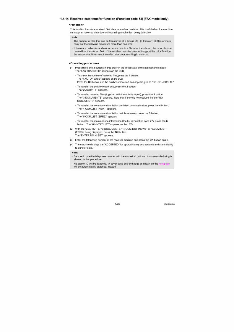
7/18/2019 Brother Mfc 9125cn 9325cw en 5694 Mfp Sm
http://slidepdf.com/reader/full/brother-mfc-9125cn-9325cw-en-5694-mfp-sm 486/597
7-28 Confidential
1.4.14 Received data transfer function (Function code 53) (FAX model only)
<Function>
This function transfers received FAX data to another machine. It is useful when the machine
cannot print received data due to the printing mechanism being defective.
<Operating procedure>
(1) Press the 5 and 3 buttons in this order in the initial state of the maintenance mode.
The “FAX TRANSFER” appears on the LCD.
- To check the number of received files, press the 1 button.
The “1.NO. OF JOBS” appears on the LCD.
Press the OK button, and the number of received files appears, just as “NO. OF. JOBS: 10.”
- To transfer the activity report only, press the 2 button.
The “2.ACTIVITY” appears.
- To transfer received files (together with the activity report), press the 3 button.
The “3.DOCUMENTS” appears. Note that if there is no received file, the “NO
DOCUMENTS” appears.
- To transfer the communication list for the latest communication, press the 4 button.
The “4.COM.LIST (NEW)” appears.
- To transfer the communication list for last three errors, press the 5 button.
The “5.COM.LIST (ERR3)” appears.
- To transfer the maintenance information (the list in Function code 77), press the 6
button. The "6.MNT77 LIST" appears on the LCD.
(2) With the “2.ACTIVITY,” “3.DOCUMENTS,” “4.COM.LIST (NEW),” or “5.COM.LIST
(ERR3)” being displayed, press the OK button.
The “ENTER NO. & SET” appears.
(3) Enter the telephone number of the receiver machine and press the OK button again.
(4) The machine displays the “ACCEPTED” for approximately two seconds and starts dialing
to transfer data.
Note:- The number of files that can be transferred at a time is 99. To transfer 100 files or more,
carry out the following procedure more than one time.
- If there are both color and monochrome data in a file to be transferred, the monochrome
data will be transferred first. If the receiver machine does not support the color function,
the sender machine cannot transfer color data, resulting in an error.
Note:
- Be sure to type the telephone number with the numerical buttons. No one-touch dialing is
allowed in this procedure.
- No station ID will be attached. A cover page and end page as shown on the next page
will be automatically attached, instead.

7/18/2019 Brother Mfc 9125cn 9325cw en 5694 Mfp Sm
http://slidepdf.com/reader/full/brother-mfc-9125cn-9325cw-en-5694-mfp-sm 487/597
7-29 Confidential
Cover page sample
Fig. 7-13
End page sample
Fig. 7-14

7/18/2019 Brother Mfc 9125cn 9325cw en 5694 Mfp Sm
http://slidepdf.com/reader/full/brother-mfc-9125cn-9325cw-en-5694-mfp-sm 488/597
7-30 Confidential
1.4.15 Fine adjustment of scan start/end positions (Function code 54)
<Function>
This function allows you to adjust the scan start/end positions on the ADF and FB unit.
<Operating procedure>
(1) Press the 5 and 4 buttons in this order in the initial state of the maintenance mode.
The “SCAN START ADJ.” will appear on the LCD.
(2) The “ . ADF . FB” will appear after two seconds.
Select one of them that you want to adjust the start position. If you want to adjust the start
position of the ADF, press button, and if you want to adjust that of the FB unit,
press button.
(3) Press the 1 or 2 button to display the present compensation level for the start position.
Compensation levels can be adjusted in 11 steps from +5 to –5 (mm).
(4) Press the button to increase compensation levels, and the button to lower them.
When the Stop/Exit button is pressed, the machine does not change the compensation
levels, and beeps for one second and returns to the initial state of the maintenance mode.
(5) Set the compensation level and press the OK button.
The “ACCEPTED” will appear on the LCD. One second later, the machine “ . ADF
. FB” will appear on the LCD.
(6) Press the Stop/Exit button when finish the adjustment. The machine beeps for one
second and returns to the initial state of the maintenance mode.
The correlation between the scan start/end positions and compensation levels is shown below.
Fig. 7-15
MAINTENANCE
ACCEPTED
:ADF : FB
SCAN START ADJ.
+-
+- +-
5 and 4 buttons select
2 seconds later OK button
Stop/Exit button
or button
buttonbutton
OK button
Stop/Exit button

7/18/2019 Brother Mfc 9125cn 9325cw en 5694 Mfp Sm
http://slidepdf.com/reader/full/brother-mfc-9125cn-9325cw-en-5694-mfp-sm 489/597
7-31 Confidential
1.4.16 Acquisition of white level data (Function code 55)
<Function>
This function allows you to acquire the white level of the scanner unit and save it to the
EEPROM of the main PCB.
<Operating procedure>
(1) Press the 5 button twice in the initial state of the maintenance mode.
(2) “Press START” will appear on the LCD. Press the Start/Black button.
“SCANNER AREA SET” will appear on the LCD.
(3) After a few seconds, the machine saves the magnification compensation setting value,
and beeps for one second and returns to the initial state of the maintenance mode.
Note:When you replace the document scanner unit, be sure to perform this procedure.

7/18/2019 Brother Mfc 9125cn 9325cw en 5694 Mfp Sm
http://slidepdf.com/reader/full/brother-mfc-9125cn-9325cw-en-5694-mfp-sm 490/597
7-32 Confidential
1.4.17 Adjustment of color registration (Function code 66)
<Function>
This function allows a service man to forcibly activate the color registration adjustment
function, which is usually executed automatically in a specified condition. If adjustment of
color registration (auto) fails because toner reaches its life, etc., you can adjust color
registration manually.
Adjustment of color registration (auto)
<Operating procedure>
(1) Press the 6 button twice in the initial state of the maintenance mode.
“REGISTRATION” is displayed on the LCD.
(2) Press the OK button. “PLEASE WAIT” is displayed on the LCD, and adjustment of color
registration is automatically done.
(3) When this operation is completed without an error, “COMPLETED” is displayed on the LCD.
(4) When the Stop/Exit button is pressed, the machine beeps for one second and returns tothe initial state of the maintenance mode.
When an error message is displayed on the LCD, take the measures described in the
table below.
* # indicates the toner color (Y, M, or C) of which cartridge became empty.
Error message Measure
REGISTRATION
FAILD
Press the Start/Black button to clear the error.
Adjust color registration manually in accordance with the
procedure for adjustment of color registration (manual) given
next page.
REGISTRATION
TONER EMPTY # *
Replace the empty toner cartridge and perform adjustment of
color registration (auto) again.
NO PAPER LOAD
A4 PAPER
Load A4-size paper in the tray and perform adjustment of color
registration (auto) again.
REGI WIDTH
ERROR
Press the Start/Black button to clear the error.
Jam Tray 1 Remove the jammed paper, and press the Start/Black button
to clear the error.Jam Rear
Cover is Open Close the cover.
K38 * Y25 M18 C30 Press the Start/Black button to clear the error.
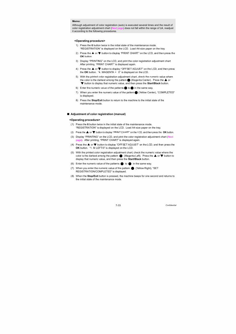
7/18/2019 Brother Mfc 9125cn 9325cw en 5694 Mfp Sm
http://slidepdf.com/reader/full/brother-mfc-9125cn-9325cw-en-5694-mfp-sm 491/597
7-33 Confidential
<Operating procedure>
1) Press the 6 button twice in the initial state of the maintenance mode.
“REGISTRATION” is displayed on the LCD. Load A4-size paper on the tray.
2) Press the or button to display “PRINT CHART” on the LCD, and then press the
OK button.
3) Display “PRINTING” on the LCD, and print the color registration adjustment chart.
After printing, “PRINT CHART” is displayed again.
4) Press the or button to display “OFFSET ADJUST” on the LCD, and then press
the OK button. “4. MAGENTA = 0” is displayed on the LCD.
5) With the printed color registration adjustment chart, check the numeric value where
the color is the darkest among the pattern (Magenta Center). Press the or
button to display that numeric value, and then press the Start/Black button.
6) Enter the numeric value of the patterns to in the same way.
7) When you enter the numeric value of the pattern (Yellow Center), “COMPLETED”
is displayed.
8) Press the Stop/Exit button to return to the machine to the initial state of the
maintenance mode.
Adjustment of color registration (manual)
<Operating procedure>
(1) Press the 6 button twice in the initial state of the maintenance mode.
“REGISTRATION” is displayed on the LCD. Load A4-size paper on the tray.
(2) Press the or button to display “PRINT CHART” on the LCD, and then press the OK button.
(3) Display “PRINTING” on the LCD, and print the color registration adjustment chart (Next
page). After printing, “PRINT CHART” is displayed again.
(4) Press the or button to display “OFFSET ADJUST” on the LCD, and then press the
OK button. “1. M LEFT/0” is displayed on the LCD.
(5) With the printed color registration adjustment chart, check the numeric value where the
color is the darkest among the pattern (Magenta Left). Press the or button to
display that numeric value, and then press the Start/Black button.
(6) Enter the numeric value of the patterns to in the same way.
(7) When you enter the numeric value of the pattern (Yellow Right), “SET
REGISTRATION/COMPLETED” is displayed.
(8) When the Stop/Exit button is pressed, the machine beeps for one second and returns to
the initial state of the maintenance mode.
Memo:
Although adjustment of color registration (auto) is executed several times and the result of
color registration adjustment chart (Next page) does not fall within the range of ±4, readjust
it according to the following procedures.
4
5 6
6
1
2 9
9
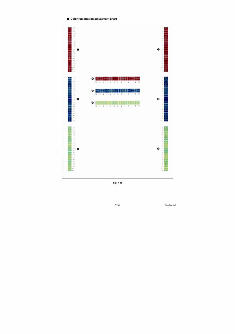
7/18/2019 Brother Mfc 9125cn 9325cw en 5694 Mfp Sm
http://slidepdf.com/reader/full/brother-mfc-9125cn-9325cw-en-5694-mfp-sm 492/597
7-34 Confidential
Color registration adjustment chart
Fig. 7-16

7/18/2019 Brother Mfc 9125cn 9325cw en 5694 Mfp Sm
http://slidepdf.com/reader/full/brother-mfc-9125cn-9325cw-en-5694-mfp-sm 493/597
7-35 Confidential
1.4.18 Continuous print test (Function code 67)
<Function>
This function allows you to conduct the pick-up and delivery test as printing patterns.
<Operating procedure>
(1) Press the 6 and 7 buttons in this order in the initial state of the maintenance mode.
(2) When “SELECT: K 100%” appears on the LCD, select a relevant continuous print pattern
using or button, and then press the OK button.
The available continuous print patterns are shown below.
* KCMY1% and KCMY5% are available only for A4 and Letter.
(3) When “SELECT: A4” appears on the LCD, select a relevant paper size using or
button, and then press the OK button.
The available paper sizes are shown below.
(4) The “PAPER FEED TEST” appears on the LCD, and print of the continuous print pattern
with the selected pick-up test items starts.
(5) When the Stop/Exit button is pressed, the machine cancels this operation, beeps for one
second and returns to the initial state of the maintenance mode.
LCD
SELECT: K 100%
SELECT: C 100%
SELECT: M 100%
SELECT: Y 100%
SELECT: R 100%
SELECT: G 100%
SELECT: B 100%
SELECT: KCMY1%*
SELECT: KCMY5%*
SELECT: Lattice
LCD
SELECT: A4
SELECT: LETTER
SELECT: LEGAL
SELECT: A5
SELECT: B6
SELECT: A6
Note:
- The machine continues the test printing until there is no paper in a tray. Press the Stop/
Exit button to stop if you check the paper feeding and ejecting operations. (Printing is
resumed when paper is loaded in the tray.)
- In the case that the error occurs during test printing, the test printing is stopped. (Printing
is resumed when the error is cleared.)
- To clear the error, remove the error factors, and then press the Start/Black button.

7/18/2019 Brother Mfc 9125cn 9325cw en 5694 Mfp Sm
http://slidepdf.com/reader/full/brother-mfc-9125cn-9325cw-en-5694-mfp-sm 494/597
7-36 Confidential
Continuous print pattern
Fig. 7-17
SELECT: K 100% SELECT: C 100% SELECT: M 100% SELECT: Y 100%
SELECT: R 100% SELECT: G 100% SELECT: B 100%
SELECT: KCMY1% SELECT: KCMY5% SELECT: Lattice

7/18/2019 Brother Mfc 9125cn 9325cw en 5694 Mfp Sm
http://slidepdf.com/reader/full/brother-mfc-9125cn-9325cw-en-5694-mfp-sm 495/597
7-37 Confidential
1.4.19 LED test pattern print (Function code 68)
<Function>
This function allows you to print the LED ASSY test pattern and check the quality of the LED
ASSY and if it is lifted from the drum.
<Operating procedure>
(1) Press the 6 and 8 buttons in this order in the initial state of the maintenance mode.
(2) When “M68_L” is displayed on the LCD, press the or button to select an
appropriate test pattern, and press the OK button.
The available test pattern is shown below.
“PRINTING” is displayed on the LCD, and the LED test pattern (refer to next page) is
printed on a sheet.
(3) When the Stop/Exit button is pressed, the machine beeps for one second and returns tothe initial state of the maintenance mode.
When an error message is displayed on the LCD, take the measures described in the table below.
* # indicates the toner color (K, Y, M, or C) of which cartridge became empty.
Note:
You can check scratches and smears on the LED by performing the continuous print test.
(Refer to “1.4.18 Continuous print test (Function code 67)” in this chapter)
LCD Description
M68_L Vertical/horizontal dot loss check pattern
Note:
When printing fails, a relevant error is displayed on the LCD. When the error factors
are removed and the Start/Black button is pressed, the machine automatically
recovers to the re-executable state. “PRINTING” is displayed on the LCD, and the test
pattern is printed on a sheet.
Error message Measure
TONER EMPTY # * Replace the empty toner cartridge and press the Start/Black
button to clear the error. Perform the LED test pattern print
again.
Cover is Open Close the top cover.
No Paper Replenish paper, and press the Start/Black button to clear
the error.
Jam Tray1 Remove the jammed paper, and press the Start/Black
button to clear the error.
Jam Rear Remove the jammed paper, and press the Start/Black
button to clear the error.
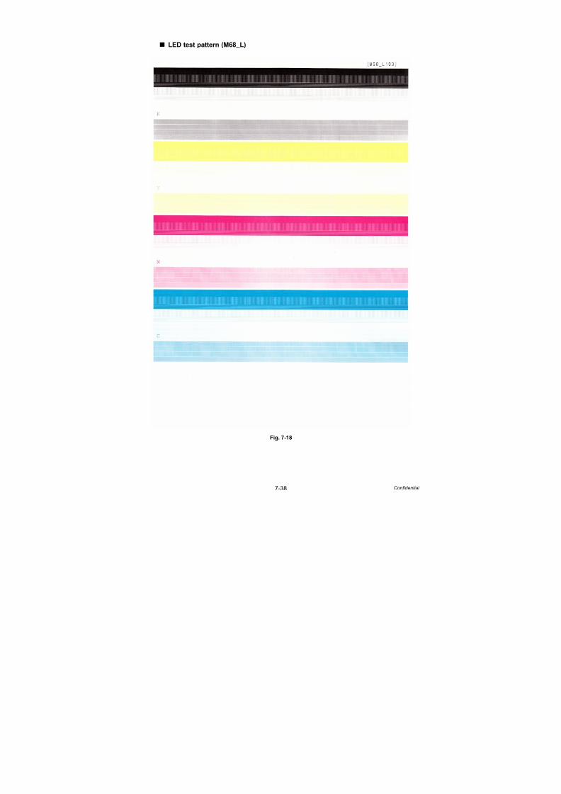
7/18/2019 Brother Mfc 9125cn 9325cw en 5694 Mfp Sm
http://slidepdf.com/reader/full/brother-mfc-9125cn-9325cw-en-5694-mfp-sm 496/597
7-38 Confidential
LED test pattern (M68_L)
Fig. 7-18

7/18/2019 Brother Mfc 9125cn 9325cw en 5694 Mfp Sm
http://slidepdf.com/reader/full/brother-mfc-9125cn-9325cw-en-5694-mfp-sm 497/597
7-39 Confidential
1.4.20 Frame pattern print (Function code 69)
<Function>
This function allows you to print the external periphery frame pattern on a sheet and check if
there is print deflection and/or loss.
<Operating procedure>
(1) Load Letter-size paper on the paper tray.
(2) Press the 6 and 9 buttons in this order in the initial state of the maintenance mode.
“PRINTING” is displayed on the LCD, and the frame pattern (see the figure below) is
printed on a sheet.
(3) When the Stop/Exit button is pressed, the machine beeps for one second and returns to
the initial state of the maintenance mode
When an error message is displayed on the LCD, take the measures described in the table below.
* # indicates the toner color (K, Y, M, or C) of which cartridge became empty.
Note:
When printing fails, a relevant error is displayed on the LCD. After the error is solved and
the Start/Black button is pressed, the machine automatically goes back to the
re-executable state, and “WAKU SX” is displayed on the LCD. When the OK button is
pressed, “PRINTING” is displayed on the LCD, and the frame pattern is printed on a sheet.
Error message Measure
TONER EMPTY # * Replace the empty toner cartridge and press the Start/Black
button to clear the error. Perform the frame pattern print
again.
Cover is Open Close the top cover.
No Paper Replenish paper, and press the Start/Black button to clear
the error.
Jam Tray1 Remove the jammed paper, and press the Start/Black
button to clear the error.
Jam Rear Remove the jammed paper, and press the Start/Black
button to clear the error.

7/18/2019 Brother Mfc 9125cn 9325cw en 5694 Mfp Sm
http://slidepdf.com/reader/full/brother-mfc-9125cn-9325cw-en-5694-mfp-sm 498/597
7-40 Confidential
Fig. 7-19

7/18/2019 Brother Mfc 9125cn 9325cw en 5694 Mfp Sm
http://slidepdf.com/reader/full/brother-mfc-9125cn-9325cw-en-5694-mfp-sm 499/597
7-41 Confidential
1.4.21 Color test pattern (Function code 71)
<Function>
This function allows you to print the pattern of each color and check if there is any smear on or
failure in the belt unit, develop roller, and exposure drum, etc.
<Operating procedure>
(1) Press the 7 and 1 buttons in this order in the initial state of the maintenance mode.
(2) When “2D3S YCMK_ _A” is displayed on the LCD, press the or button to select an
appropriate print pattern, and press the OK button.
(3) “PRINTING” is displayed on the LCD, and the color test pattern (see the figure below) is printed.
The available print patterns are shown below.
* In the full page print mode, the cleaning operation is performed between printing of M and K.
(4) When printing is finished, the screen returns to the print pattern display. To print the solid
color test pattern again, press the OK button.
(5) When the Stop/Exit button is pressed, the machine beeps for one second and returns to
the initial state of the maintenance mode.
When an error message is displayed on the LCD, take the measures described in the table below.
* # indicates the toner color (K, Y, M, or C) of which cartridge became empty.
LCD Description
2D3S YCMK_ _A One sheet for each color with full page print mode* Total 4 sheets
2D3S MCYK 4-color horizontal band Total 1 sheet
2D3S Y Yellow Total 1 sheet
2D3S C Cyan Total 1 sheet
2D3S M Magenta Total 1 sheet
2D3S K Black Total 1 sheet
Note:
When printing fails, a relevant error is displayed on the LCD. When the error factors
are removed and the Start/Black button is pressed, the machine automatically
recovers to the re-executable state. “PRINTING” is displayed on the LCD, and the
color test pattern is printed.
Error message Measure
TONER EMPTY # * Replace the empty toner cartridge and press the Start/Black
button to clear the error. Perform the color test pattern print
again.
Cover is Open Close the top cover.
No Paper Replenish paper, and press the Start/Black button to clear
the error.
Jam Tray1 Remove the jammed paper, and press the Start/Black
button to clear the error.
Jam Rear Remove the jammed paper, and press the Start/Black
button to clear the error.

7/18/2019 Brother Mfc 9125cn 9325cw en 5694 Mfp Sm
http://slidepdf.com/reader/full/brother-mfc-9125cn-9325cw-en-5694-mfp-sm 500/597
7-42 Confidential
Color test pattern
Fig. 7-20
MCYK
Y C KM
YCMK_ _A
7/18/2019 Brother Mfc 9125cn 9325cw en 5694 Mfp Sm
http://slidepdf.com/reader/full/brother-mfc-9125cn-9325cw-en-5694-mfp-sm 501/597
7-43 Confidential
1.4.22 Sensitivity adjustment of density sensor (Function code 72)
<Function>
This function allows you to print the patch data for density sensor sensitivity adjustment on the
belt unit and measure the density with the density sensor. The characteristics of the density
sensor are calculated based on the value measured by the density sensor, and the parameter
is adjusted upon color density adjustment.
<Operating procedure>
(1) Press the 7 and 2 buttons in this order in the initial state of the maintenance mode.
“PLEASE WAIT” is displayed on the LCD.
(2) When the acquisition of the parameters is finished without error, the machine beeps for
one second and returns to the initial state of the maintenance mode.
When an error message is displayed on the LCD, take the measures described in the table below.
* # indicates the toner color (Y, M, or C) of which cartridge became empty.
Error message Measure
FAILED Remove the error factors with the following operations and
press the Start/Black button to clear the error.
- Re-insert the toner cartridge in the correct position.
- Replace the toner cartridge.
- Replace the drum unit.
- Replace the belt unit.
- Replace the registration sensor holder ASSY.
TONER EMPTY # * Replace the empty toner cartridge and press the Start/Black
button to clear the error. Perform the sensitivity adjustment
of the density sensor again.
Cover is Open Close the top cover.
Replace Toner Replace the toner cartridge.
No Paper Replenish paper, and press the Start/Black button to clear
the error.
Jam Tray1 Remove the jammed paper, and press the Start/Black
button to clear the error.
Jam Rear Remove the jammed paper, and press the Start/Black
button to clear the error.
7/18/2019 Brother Mfc 9125cn 9325cw en 5694 Mfp Sm
http://slidepdf.com/reader/full/brother-mfc-9125cn-9325cw-en-5694-mfp-sm 502/597
7-44 Confidential
1.4.23 Setting by country (Function code 74)
<Function>
This function allows you to customize the EEPROM according to language, function settings,
and worker switch settings.
<Operating procedure>
(1) Press the 7 and 4 buttons in this order in the initial state of the maintenance mode.
The present customizing code is displayed.
(2) Enter the desired customizing code (e.g., MFC-9320CW (USA): 0201). The newly
entered code appears.
To enter letters “A” through “F”, press the 1 through 6 buttons while holding down the #
button respectively.
(3) Press the OK button.
The machine saves the setting and displays the “PARAMETER INIT” on the LCD.
The machine beeps for one second and returns to the initial state of the maintenance
mode.
Note:If you replace the main PCB, be sure to carry out this procedure.
Note:The machine does not work properly when an incorrect code is entered.
Memo:
When the Stop/Exit button is pressed, or when no button is pressed for one second
procedure during the above procedure, the machine cancels the above, beeps for one
second and returns to the initial state of the maintenance mode.In this case, the modified setting data is not saved.

7/18/2019 Brother Mfc 9125cn 9325cw en 5694 Mfp Sm
http://slidepdf.com/reader/full/brother-mfc-9125cn-9325cw-en-5694-mfp-sm 503/597
7-45 Confidential
<EEPROM customizing code list>
* Country codes are subject to change without notice.
CountryDCP-9010CNMFC-9010CN
MFC-9120CN
MFC-9320CW
MFC-9125CN
MFC-9325CW
USA 0001 0101 0201 0001 0101
Canada 0002 0102 0202 0002 0102
Chile, Argentina --- 0136 --- --- ---
Brazil 0042 --- 0242 --- ---
Germany 1004 0103 0203 --- ---
UK 1004 0104 0204 --- ---
France 1004 (1055) 0105 0205 --- ---
Norway 1004 0107 (0157) 0207 --- ---
Belgium 1008 (1055) 0108 0208 --- ---
Netherlands 1004 (1055) 0109 0209 --- ---
Switzerland 1010 0110 0210 --- ---
Finland 1004 0112 (0157) 0212 --- ---
Denmark 1004 0113 (0157) 0213 --- ---
Austria 1004 0103 0203 --- ---
Spain 1015 (1065) 0115 0215 --- ---
Italy 1004 0116 0216 --- ---
Portugal 1004 (1065) 0118 0218 --- ---
Israel --- 0150 --- --- ---
South Africa 1004 --- --- --- ---
Sweden 1004 0126 (0157) 0226 --- ---
Slovakia 1004 0130 (0188) 0230 (0288) --- ---
Bulgaria 1004 0132 (0188) 0232 (0288) --- ---
Rumania 1004 0133 (0188) 0233 (0288) --- ---
Czech 1004 0137 (0188) 0237 (0288) --- ---
Hungary 1004 0138 (0188) 0238 (0288) --- ---
Russia 1004 0148 0248 --- ---
Poland 1004 0139 (0188) 0239 (0288) --- ---
Pan-Nordic 1004 0157 0257 --- ---
General 1004 0150 (0188) 0250 --- ---
EEU General 1004 0150 0250 (0288) --- ---
Singapore, HongKong, Gulf
0004 0140 0240 --- ---
Australia 0004 0106 (0156) 0206 (0256) 0006 (0056) 0106 (0156)
New Zealand 0004 0127 (0156) 0227 (0256) 0027 (0056) 0127 (0156)
China 0020 0120 0220 --- ---
South Africa, Gulf 0024 0124 0224 --- ---
India 0045 0145 0245 --- ---
Turkey 0004 0125 0225 --- ---
Note:
- If you can determine the country where the customer uses the machine, enter thecode outside the brackets. If not, enter the code inside.
- The information provided in this page is as of August 2011. Regarding the latestsetting codes, see the ROM/ firmware information provided by Brother Industries, Ltd.

7/18/2019 Brother Mfc 9125cn 9325cw en 5694 Mfp Sm
http://slidepdf.com/reader/full/brother-mfc-9125cn-9325cw-en-5694-mfp-sm 504/597
7-46 Confidential
1.4.24 Sensitivity adjustment of registration mark sensor and check of beltsurface (Function code 75)
<Function>
This function makes the registration mark sensor to adjust its sensitivity compulsory. This
allows you to check if the registration mark sensor works properly. This function makes themachine to check the surface of the belt unit by using the registration mark sensor as well.
<Operating procedure>
(1) Press the 7 and 5 buttons in this order in the initial state of the maintenance mode.
“REGI SENS ADJUST” is displayed on the LCD.
(2) Press the or button to select the appropriate item.
(3) Press the OK button to execute the selected item.
(4) When the operation is finished, the machine beeps for one second and returns to the
initial state of the maintenance mode.
LCD Description
REGI_SENS ADJUST
BELT OFF
Adjust the sensitivity of the registration mark sensor when the belt
unit is not operated. This is to check whether the registration
mark sensor’s operation is okay or not.
REGI_SENS ADJUST
BELT ON
Adjust the sensitivity of the registration mark sensor while the belt
unit is driving. (This is the same as the sensitivity adjustment
performed before adjustment of color registration.)
REGI_SENS ADJUST
BELT CHECK
Check that there are no scratches on the surface of the belt unit of
the registration mask sensor.
Note:
- If you press the OK button during the sensitivity adjustment or after the error message
appears on the LCD, the sensitivity adjustment is started again.
- In the case that the error occurs, refer to the next page to check the error description and
the way to solve it.

7/18/2019 Brother Mfc 9125cn 9325cw en 5694 Mfp Sm
http://slidepdf.com/reader/full/brother-mfc-9125cn-9325cw-en-5694-mfp-sm 505/597
7-47 Confidential
Error display when “REGI_SENS ADJUST BELT OFF” or “REGI_SENS ADJUST
BELT CHECK” is executed
Error display when “REGI_SENS ADJUST BELT ON” is executed
* XX shows the number of error times (1 to 999) when a scratch is detected on the surface of
the belt unit. If the number of times is larger, the condition of the belt unit is worse.
Error messages Description Solution
REGI_SENS ADJUST
Write Err
Failure to write electronic
volume NVRAM
Replace the engine PCB
ASSY.
REGI_SENS ADJUST
Belt Left Err
Measurement data error
upon sensitivity adjustment
of the registration mark
sensor L
Replace the belt unit. If you
do not replace it, execute the
adjustment of color
registration (manual).
(Refer to “Adjustment of
color registration (Function
code 66)” in this chapter .)
REGI_SENS ADJUST
Belt Right Err
Measurement data error
upon sensitivity adjustment
of the registration mark
sensor R
Error messages Description Solution
REGI_L_SENS: XXX
REGI_R_SENS: OK
Result of the belt unit
surface check within the
coverage of the registration
mark sensor L
Execute the adjustment of
color registration (manual).
If the error occurs again,
replace the belt unit.
(Refer to “Adjustment of
color registration (Function
code 66)” in this chapter .)
REGI_L_SENS: OK
REGI_R_SENS: XXX
Result of the belt unit
surface check within the
coverage of the registration
mark sensor R
REGI_L_SENS: XXX
REGI_R_SENS: XXX
Result of the belt unit
surface check within the
coverage of the registration
mark sensor
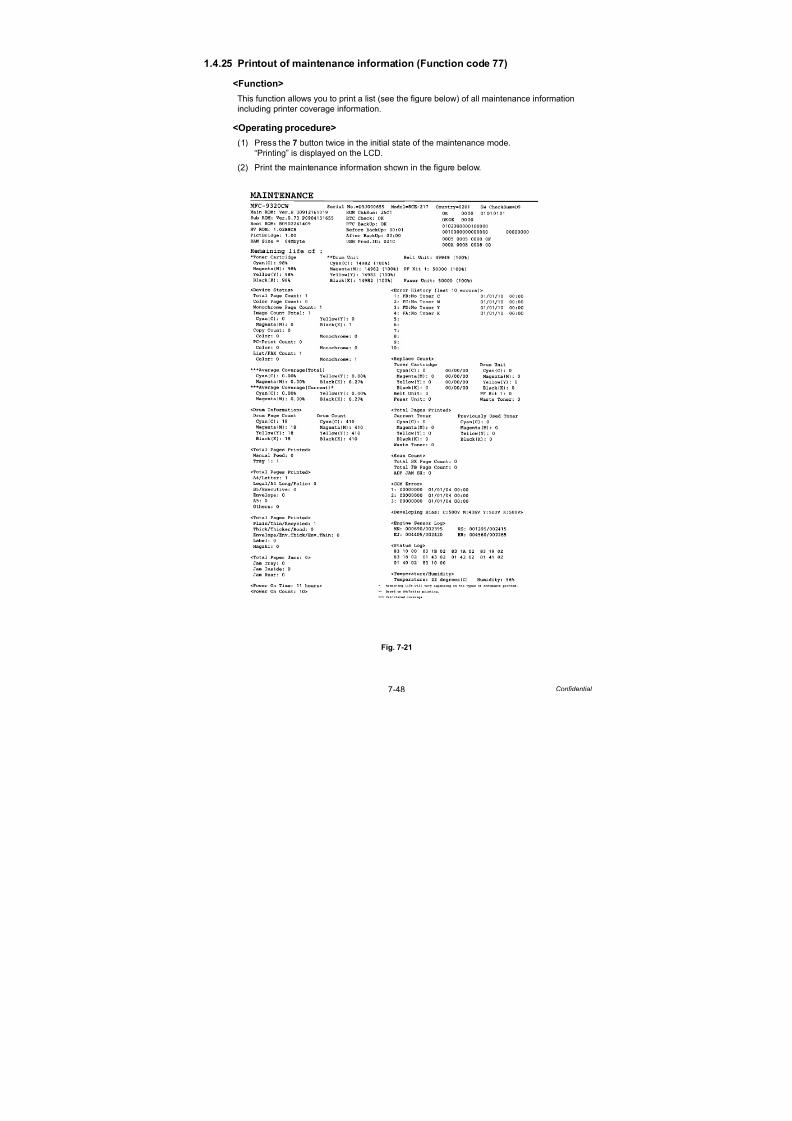
7/18/2019 Brother Mfc 9125cn 9325cw en 5694 Mfp Sm
http://slidepdf.com/reader/full/brother-mfc-9125cn-9325cw-en-5694-mfp-sm 506/597
7-48 Confidential
1.4.25 Printout of maintenance information (Function code 77)
<Function>
This function allows you to print a list (see the figure below) of all maintenance information
including printer coverage information.
<Operating procedure>
(1) Press the 7 button twice in the initial state of the maintenance mode.
“Printing” is displayed on the LCD.
(2) Print the maintenance information shown in the figure below.
Fig. 7-21

7/18/2019 Brother Mfc 9125cn 9325cw en 5694 Mfp Sm
http://slidepdf.com/reader/full/brother-mfc-9125cn-9325cw-en-5694-mfp-sm 507/597
7-49 Confidential
1.4.26 Operational check of fans (Function code 78)
<Function>
This function is to check whether each of fans is operating correctly or not. The operation of
the following fans is checked respectively, and their operating states (rotation speed 100 %,
rotation speed 50 %, or OFF) are displayed.
<Operating procedure>
(1) Press the 7 and 8 buttons in this order in the initial state of the maintenance mode.
The indication will appear on the LCD as shown in the figure below.
(2) Press the Start/Black button to check the next item. For operation check, spin or stop
fans actually on each item.
(3) Press the Stop/Exit button so that the machine stops checking the fans, beeps for one
second and returns to the initial state of the maintenance mode.
Fig. 7-22
Location of fans
Fig. 7-23
LCD Parts name Description
FU Main fan Evacuate hot air of the fuser unit.
PS LV fan Evacuate hot air of the Low-voltage power supply PCB.
LV fan
Main fan
Exhaust
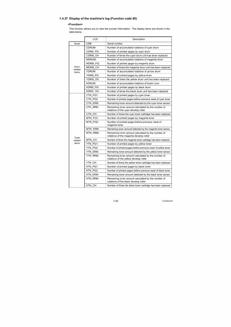
7/18/2019 Brother Mfc 9125cn 9325cw en 5694 Mfp Sm
http://slidepdf.com/reader/full/brother-mfc-9125cn-9325cw-en-5694-mfp-sm 508/597
7-50 Confidential
1.4.27 Display of the machine’s log (Function code 80)
<Function>
This function allows you to view the counter information. The display items are shown in the
table below.
LCD Description
Serial USB: Serial number
Drum
related
items
CDRUM: Number of accumulated rotations of cyan drum
CDRM_PG: Number of printed pages by cyan drum
CDRM_CH: Number of times the cyan drum unit has been replaced
MDRUM: Number of accumulated rotations of magenta drum
MDRM_PG: Number of printed pages by magenta drum
MDRM_CH: Number of times the magenta drum unit has been replaced
YDRUM: Number of accumulated rotations of yellow drum
YDRM_PG: Number of printed pages by yellow drum
YDRM_CH: Number of times the yellow drum unit has been replaced
KDRUM: Number of accumulated rotations of black drum
KDRM_PG: Number of printed pages by black drum
KDRM_CH: Number of times the black drum unit has been replaced
Toner
related
items
CTN_PG1: Number of printed pages by cyan toner
CTN_PG2: Number of printed pages before previous reset of cyan toner
CTN_ERM: Remaining toner amount detected by the cyan toner sensor
CTN_RRM: Remaining toner amount calculated by the number of
rotations of the cyan develop roller CTN_CH: Number of times the cyan toner cartridge has been replaced
MTN_PG1: Number of printed pages by magenta toner
MTN_PG2: Number of printed pages before previous reset of
magenta toner
MTN_ERM: Remaining toner amount detected by the magenta toner sensor
MTN_RRM: Remaining toner amount calculated by the number of
rotations of the magenta develop roller
MTN_CH: Number of times the magenta toner cartridge has been replaced
YTN_PG1: Number of printed pages by yellow toner
YTN_PG2: Number of printed pages before previous reset of yellow toner
YTN_ERM: Remaining toner amount detected by the yellow toner sensor
YTN_RRM: Remaining toner amount calculated by the number of
rotations of the yellow develop roller
YTN_CH: Number of times the yellow toner cartridge has been replaced
KTN_PG1: Number of printed pages by black toner
KTN_PG2: Number of printed pages before previous reset of black toner
KTN_ERM: Remaining toner amount detected by the black toner sensor
KTN_RRM: Remaining toner amount calculated by the number of
rotations of the black develop roller
KTN_CH: Number of times the black toner cartridge has been replaced
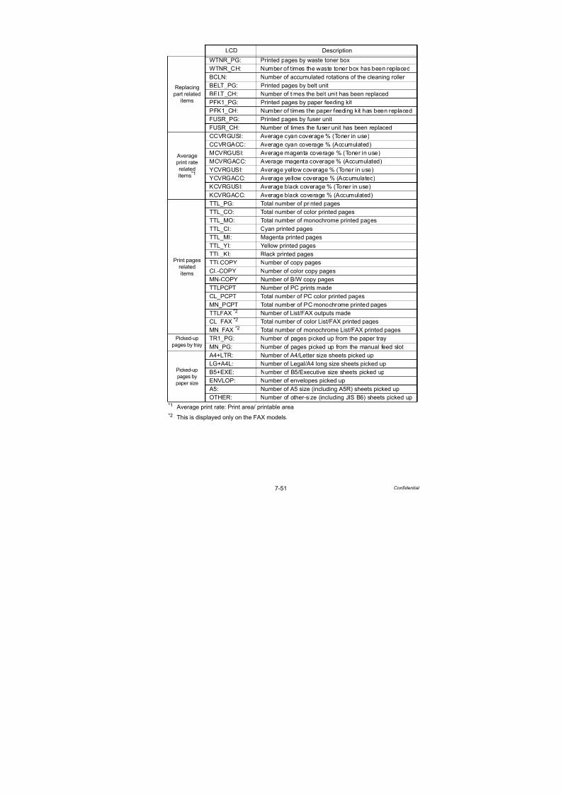
7/18/2019 Brother Mfc 9125cn 9325cw en 5694 Mfp Sm
http://slidepdf.com/reader/full/brother-mfc-9125cn-9325cw-en-5694-mfp-sm 509/597
7-51 Confidential
*1 Average print rate: Print area/ printable area
*2 This is displayed only on the FAX models.
LCD Description
Replacingpart related
items
WTNR_PG: Printed pages by waste toner box
WTNR_CH: Number of times the waste toner box has been replaced
BCLN: Number of accumulated rotations of the cleaning roller
BELT_PG: Printed pages by belt unit
BELT_CH: Number of times the belt unit has been replaced
PFK1_PG: Printed pages by paper feeding kit
PFK1_CH: Number of times the paper feeding kit has been replaced
FUSR_PG: Printed pages by fuser unit
FUSR_CH: Number of times the fuser unit has been replaced
Average
print rate
related
items*1
CCVRGUSI: Average cyan coverage % (Toner in use)
CCVRGACC: Average cyan coverage % (Accumulated)
MCVRGUSI: Average magenta coverage % (Toner in use)
MCVRGACC: Average magenta coverage % (Accumulated)
YCVRGUSI: Average yellow coverage % (Toner in use)
YCVRGACC: Average yellow coverage % (Accumulated)KCVRGUSI: Average black coverage % (Toner in use)
KCVRGACC: Average black coverage % (Accumulated)
Print pages
relateditems
TTL_PG: Total number of printed pages
TTL_CO: Total number of color printed pages
TTL_MO: Total number of monochrome printed pages
TTL_CI: Cyan printed pages
TTL_MI: Magenta printed pages
TTL_YI: Yellow printed pages
TTL_KI: Black printed pages
TTLCOPY Number of copy pages
CL-COPY Number of color copy pages
MN-COPY Number of B/W copy pages
TTLPCPT Number of PC prints made
CL_PCPT Total number of PC color printed pages
MN_PCPT Total number of PC monochrome printed pages
TTLFAX *2 Number of List/FAX outputs made
CL_FAX *2 Total number of color List/FAX printed pages
MN_FAX *2 Total number of monochrome List/FAX printed pages
Picked-up
pages by tray
TR1_PG: Number of pages picked up from the paper tray
MN_PG: Number of pages picked up from the manual feed slot
Picked-up
pages by
paper size
A4+LTR: Number of A4/Letter size sheets picked upLG+A4L: Number of Legal/A4 long size sheets picked up
B5+EXE: Number of B5/Executive size sheets picked up
ENVLOP: Number of envelopes picked up
A5: Number of A5 size (including A5R) sheets picked up
OTHER: Number of other-size (including JIS B6) sheets picked up
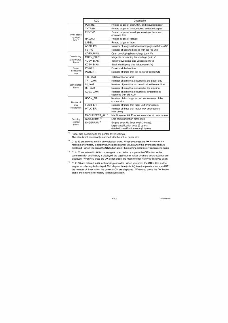
7/18/2019 Brother Mfc 9125cn 9325cw en 5694 Mfp Sm
http://slidepdf.com/reader/full/brother-mfc-9125cn-9325cw-en-5694-mfp-sm 510/597
7-52 Confidential
*3 Paper size according to the printer driver settings.
This size is not necessarily matched with the actual paper size.
*4 01 to 10 are entered in ## in chronological order . When you press the OK button as the
machine error history is displayed, the page counter values when the errors occurred aredisplayed. When you press the OK button again, the machine error history is displayed again.
*5 01 to 03 are entered in ## in chronological order. When you press the OK button as the
communication error history is displayed, the page counter values when the errors occurred are
displayed. When you press the OK button again, the machine error history is displayed again.
*6 01 to 10 are entered in ## in chronological order. When you press the OK button as the
engine error history is displayed, TM: elapsed time (minute) from the previous error and BT:
the number of times when the power is ON are displayed. When you press the OK button
again, the engine error history is displayed again.
LCD Description
Print pages
by paper
type*3
PLTNRE: Printed pages of plain, thin, and recycled paper
TKTRBD: Printed pages of thick, thicker, and bond paper
ENVTYP: Printed pages of envelope, envelope thick, and
envelope thinHAGAKI: Printed pages of Hagaki
LABEL: Printed pages of label
ADSX_PG Number of single-sided scanned pages with the ADF
FB_PG Number of scanned pages with the FB unit
Developing
bias related
items
CDEV_BIAS: Cyan developing bias voltage (unit: V)
MDEV_BIAS: Magenta developing bias voltage (unit: V)
YDEV_BIAS: Yellow developing bias voltage (unit: V)
KDEV_BIAS: Black developing bias voltage (unit: V)
Power
distribution
time
POWER: Power distribution time
PWRCNT: Number of times that the power is turned ON
Jam related
items
TTL_JAM: Total number of jams
TR1_JAM: Number of jams that occurred at the paper tray
IN_JAM: Number of jams that occurred inside the machine
RE_JAM: Number of jams that occurred at the ejecting
ADSX_JAM: Number of jams that occurred at singled sided
scanning with the ADF
Number of
error
occurrences
HODN_ER: Number of discharge errors due to smear of the
corona wire
FUSR_ER: Number of times that fuser unit error occurs
MTLK_ER: Number of times that motor lock error occurs(Not used)
Error log
related
items
MACHINEERR_##: *4 Machine error ##: Error code/number of occurrences
COMERR##: *5 Last communication error code
ENGERR##: *6 Engine error ##: Error level (2 bytes),
large classification code (2 bytes),
detailed classification code (2 bytes)

7/18/2019 Brother Mfc 9125cn 9325cw en 5694 Mfp Sm
http://slidepdf.com/reader/full/brother-mfc-9125cn-9325cw-en-5694-mfp-sm 511/597
7-53 Confidential
<Operating procedure>
(1) Press the 8 and 0 buttons in this order in the initial state of the maintenance mode.
(2) Each time the Start/Black button is pressed, next log information item appears on the
LCD in the order.
Press the button to go to the next item.
Press the button to go back to the previous item.
(3) Press the Stop/Exit button to return the machine to the initial state of the maintenance
1.4.28 Error code indication (Function code 82)
<Function>
This function displays an error code of the machine on the LCD.
<Operating procedure>
(1) Press the 8 and 2 buttons in this order in the initial state of the maintenance mode.
The machine displays “MACHINE ERROR X X” on the LCD.
(2) When the Stop/Exit button is pressed, the machine beeps for one second and returns to
the initial state of the maintenance mode.
Note:
Regarding “MACHINEERR”, “COMERR”, and “ENGERR”, when the OK button is pressed
while the error history is displayed, the page counter value at which the error occurred is
displayed.
Press the OK button again to return the machine to the error history display.
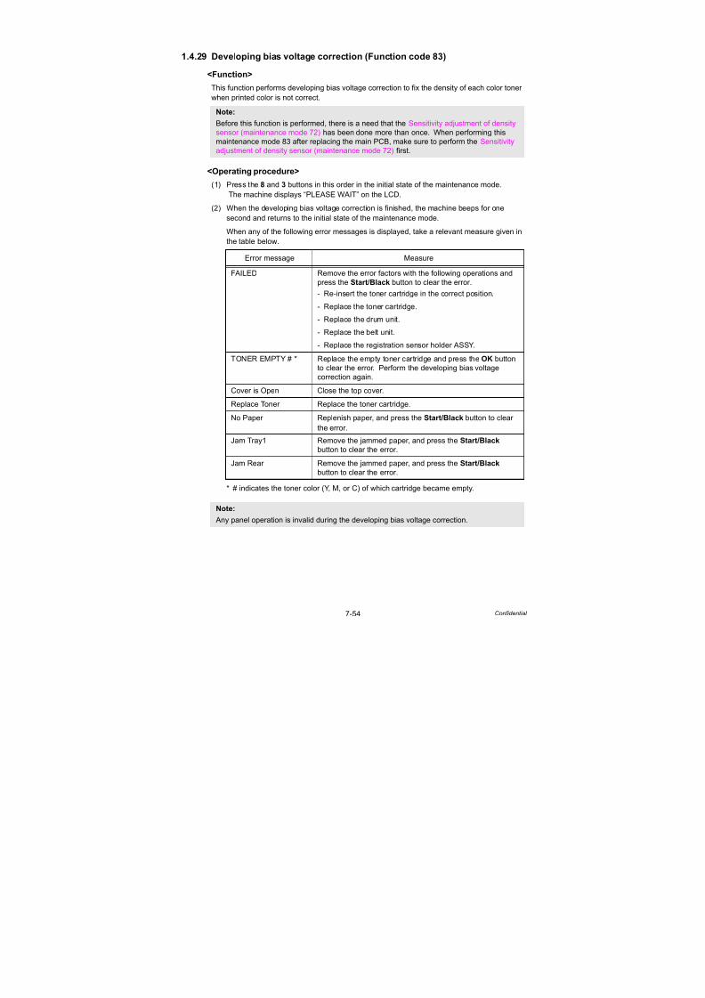
7/18/2019 Brother Mfc 9125cn 9325cw en 5694 Mfp Sm
http://slidepdf.com/reader/full/brother-mfc-9125cn-9325cw-en-5694-mfp-sm 512/597
7-54 Confidential
1.4.29 Developing bias voltage correction (Function code 83)
<Function>
This function performs developing bias voltage correction to fix the density of each color toner
when printed color is not correct.
<Operating procedure>
(1) Press the 8 and 3 buttons in this order in the initial state of the maintenance mode.
The machine displays “PLEASE WAIT” on the LCD.
(2) When the developing bias voltage correction is finished, the machine beeps for one
second and returns to the initial state of the maintenance mode.
When any of the following error messages is displayed, take a relevant measure given in
the table below.
* # indicates the toner color (Y, M, or C) of which cartridge became empty.
Note:Before this function is performed, there is a need that the Sensitivity adjustment of density
sensor (maintenance mode 72) has been done more than once. When performing this
maintenance mode 83 after replacing the main PCB, make sure to perform the Sensitivity
adjustment of density sensor (maintenance mode 72) first.
Error message Measure
FAILED Remove the error factors with the following operations and
press the Start/Black button to clear the error.
- Re-insert the toner cartridge in the correct position.
- Replace the toner cartridge.
- Replace the drum unit.
- Replace the belt unit.
- Replace the registration sensor holder ASSY.
TONER EMPTY # * Replace the empty toner cartridge and press the OK button
to clear the error. Perform the developing bias voltage
correction again.
Cover is Open Close the top cover.
Replace Toner Replace the toner cartridge.
No Paper Replenish paper, and press the Start/Black button to clear
the error.
Jam Tray1 Remove the jammed paper, and press the Start/Black
button to clear the error.
Jam Rear Remove the jammed paper, and press the Start/Black
button to clear the error.
Note:
Any panel operation is invalid during the developing bias voltage correction.

7/18/2019 Brother Mfc 9125cn 9325cw en 5694 Mfp Sm
http://slidepdf.com/reader/full/brother-mfc-9125cn-9325cw-en-5694-mfp-sm 513/597
7-55 Confidential
1.4.30 Output of transmission log to the telephone line (Function code 87)
<Function>
This function outputs the transmission log (that the machine has stored about the latest
transmission) to the telephone line. It allows the service personnel to receive the transmission
log of the user's machine at a remote location and use it for analyzing problems arising in the
user's machine.
<Operating procedure>
(1) If the user's machine has a transmission-related problem, call the user's machine at a
remote location from your machine.
(2) If the line is connected, have the user perform the following:
1) Hook up to the external phone.
2) Press the Menu, Start/Black, Menu buttons in this order.
3) Press the 8 and 7 buttons.
The above operation makes the user's machine send CNG to your machine for sending
the transmission log.
(3) If you hear the CNG sent from the user's machine, press the Start/Black button of your
machine. Your machine will start to receive the transmission log from the user's machine.
1.4.31 Counter reset after replacing the fuser unit and paper feeding kit(Function code 88)
<Function>
The number of replacement is increased by one, and the warning indication “Replace ***” is
cleared, with implementing this operation after replacing the fuser unit and paper feed Kit.
<Operating procedure>
(1) Press the 8 button twice in the initial state of the maintenance mode.
(2) The LCD shows the “Reset Fuser Unit”.
(3) Press the or button to select the item you want to reset. The LCD shows.
“Reset-Fuser Unit”
“Reset PF-KIT T”
(4) Press the OK or Start/Black button, then “OK?” will appear on the LCD.
(5) Press the OK or Start/Black button to reset the counter of the selected part and returns
the operating procedure (2) mode.(6) When the Stop/Exit button is pressed, the machine beeps for one second and returns to
the initial state of the maintenance mode.
1.4.32 Exit from maintenance mode (Function code 99)
<Function>
The machine returns to the ready state.
<Operating procedure>
(1) Press the 9 button twice in the initial state of the maintenance mode.(2) The maintenance mode is finished, and the machine returns to the ready state.

7/18/2019 Brother Mfc 9125cn 9325cw en 5694 Mfp Sm
http://slidepdf.com/reader/full/brother-mfc-9125cn-9325cw-en-5694-mfp-sm 514/597
7-56 Confidential
2. OTHER SERVICE FUNCTIONS
2.1 Resetting the Periodical Maintenance Parts Life
2.1.1 Resetting the life counter of the belt unit
<Function>
This function allows you to reset the page counter of the belt unit and increase the number of
replacement times by one.
<Operating procedure>
(1) Press the 3 and 9 buttons at the same time in the ready state.
The “Reset Menu/Drum” will appear on the LCD.
(2) Press the button a few times to select “Belt Unit”.
(3) Press the OK button.The “Belt Unit/1. Reset 2. Exit” will appear on the LCD.
(4) Press the 1 button when resetting the life counter of the belt unit. Press the 2 button if not
resetting.
(5) The “Belt Unit/Accepted” will appear on the LCD if pressing the 1 button. The page
counter of the belt unit is reset, and the number of replacement times is increased by one.
Then, the machine returns to the ready state. If pressing the 2 button, the machine do not
reset the page counter and the “Belt Unit” will appear on the LCD.
2.1.2 Resetting the life counter of the fuser unit<Function>
This function allows you to reset the page counter of the fuser unit and increase the number of
replacement times by one.
<Operating procedure>
(1) Press the 3 and 9 buttons at the same time in the ready state.
The “Reset Menu/Drum” will appear on the LCD.
(2) Press the button a few times to select “Fuser”.
(3) Press the OK button.
The “Fuser/1. Reset 2. Exit” will appear on the LCD.
(4) Press the 1 button when resetting the life counter of the fuser unit. Press the 2 button if
not resetting.
(5) The “Fuser/Accepted” will appear on the LCD if pressing the 1 button. The page counter
of the fuser unit is reset, and the number of replacement times is increased by one. Then,
the machine returns to the ready state. If pressing the 2 button, the machine do not reset
the page counter and the “Fuser” will appear on the LCD.
7/18/2019 Brother Mfc 9125cn 9325cw en 5694 Mfp Sm
http://slidepdf.com/reader/full/brother-mfc-9125cn-9325cw-en-5694-mfp-sm 515/597
7-57 Confidential
2.1.3 Resetting the life counter of the drum unit
<Function>
This function allows you to reset the page counter of the drum unit and increase the number of
replacement times by one.
<Operating procedure>
(1) Press the 3 and 9 buttons at the same time in the ready state.
The “Reset Menu/Drum” will appear on the LCD.
(2) Press the button a few times to select “Drum Unit”.
(3) Press the OK button. The “Drum/Black(K)” will appear on the LCD.
(4) Or select the color to be reset by using the or button.
(5) Press the OK button.
The “Drum Unit/1. Reset 2. Exit” will appear on the LCD.
(6) Press the 1 button when resetting the life counter of the drum unit. Press the 2 button if
not resetting.
(7) The “Drum Unit/Accepted” will appear on the LCD if pressing the 1 button. The page
counter of the drum unit is reset, and the number of replacement times is increased by
one. Then, the machine returns to the ready state. If pressing the 2 button, the machine
do not reset the page counter and the “Drum Unit” will appear on the LCD.
2.1.4 Resetting the life counter of the paper feeding kit
<Function>
This function allows you to reset the page counter of the paper feeding kit and increase the
number of replacement times by one.
<Operating procedure>
(1) Press the 3 and 9 buttons at the same time in the ready state.
The “Reset Menu/Drum” will appear on the LCD.
(2) Press the button a few times to select “PF Kit”.
(3) Press the OK button.
The “PF Kit/1. Reset 2. Exit” will appear on the LCD.
(4) Press the 1 button when resetting the life counter of the paper feeding kit. Press the 2
button if not resetting.
(5) The “PF Kit/Accepted” will appear on the LCD if pressing the 1 button. The page counter
of the paper feeding kit is reset, and the number of replacement times is increased by
one. Then, the machine returns to the ready state. If pressing the 2 button, the machine
do not reset the page counter and the “PF Kit” will appear on the LCD.

7/18/2019 Brother Mfc 9125cn 9325cw en 5694 Mfp Sm
http://slidepdf.com/reader/full/brother-mfc-9125cn-9325cw-en-5694-mfp-sm 516/597
7-58 Confidential
2.2 Develop Roller Counter Reset Function
This function is to manually perform the operation same as the one when a toner cartridge is
replaced with a new one. The purpose of this function is to provide a means to resolve an error
when a new toner cannot be recognized by the product, and the LCD display fails to be cleared.
<Operating procedure>
(1) Press the Clear/Back button while the top cover is being
opened.
(2) “K. TNR-STD” appears on the LCD.
Press the or button to select the appropriate toner
cartridge, and then press the OK button.
LCD Description
K.TNR-STD Reset the develop roller counter of
standard black toner cartridge.
K.TNR-STR Reset the develop roller counter of
starter black toner cartridge.
C.TNR-STD Reset the develop roller counter of
standard cyan toner cartridge.
C.TNR-STR Reset the develop roller counter of
starter cyan toner cartridge.
M.TNR-STD Reset the develop roller counter of
standard magenta toner cartridge.
M.TNR-STR Reset the develop roller counter ofstarter magenta toner cartridge.
Y.TNR-STD Reset the develop roller counter of
standard yellow toner cartridge.
Y.TNR-STR Reset the develop roller counter of
starter yellow toner cartridge.
(3) The “K. TNR-STD/1. Reset 2.Exit” will appear on the
LCD. If resetting the counter, press the 1 button. If not,
press the 2 button.
(4) The develop roller counter is reset.
(5) The machine returns to the state in which the top cover is
open.
Note:
- If there is no operation for 30 seconds or more, the machine automatically returns to step (1).- While starter toner is also displayed on the LCD, make sure to select standard toner.

7/18/2019 Brother Mfc 9125cn 9325cw en 5694 Mfp Sm
http://slidepdf.com/reader/full/brother-mfc-9125cn-9325cw-en-5694-mfp-sm 517/597
7-59 Confidential
2.3 How to Recover from Errors of the Fuser Unit
How to recover from errors of the fuser unit is to use Function code 99 in the maintenance mode.
WARNING
When clearing an error, be sure that the fuser unit is cooled down sufficiently. If an error iscleared while the fuser unit is not cooled down, there is a possibility that the unit might be
unable to be repaired.

7/18/2019 Brother Mfc 9125cn 9325cw en 5694 Mfp Sm
http://slidepdf.com/reader/full/brother-mfc-9125cn-9325cw-en-5694-mfp-sm 518/597
Confidential
CHAPTER 8CIRCUIT DIAGRAMS & WIRING DIAGRAM

7/18/2019 Brother Mfc 9125cn 9325cw en 5694 Mfp Sm
http://slidepdf.com/reader/full/brother-mfc-9125cn-9325cw-en-5694-mfp-sm 519/597
Confidential
CHAPTER 8
CIRCUIT DIAGRAMS & WIRING DIAGRAMThis chapter provides the circuit diagrams and wiring diagram for the connections of the PCBs.
CONTENTS
1. CIRCUIT DIAGRAMS.................................................................................8-1
2. WIRING DIAGRAM ..................................................................................8-12
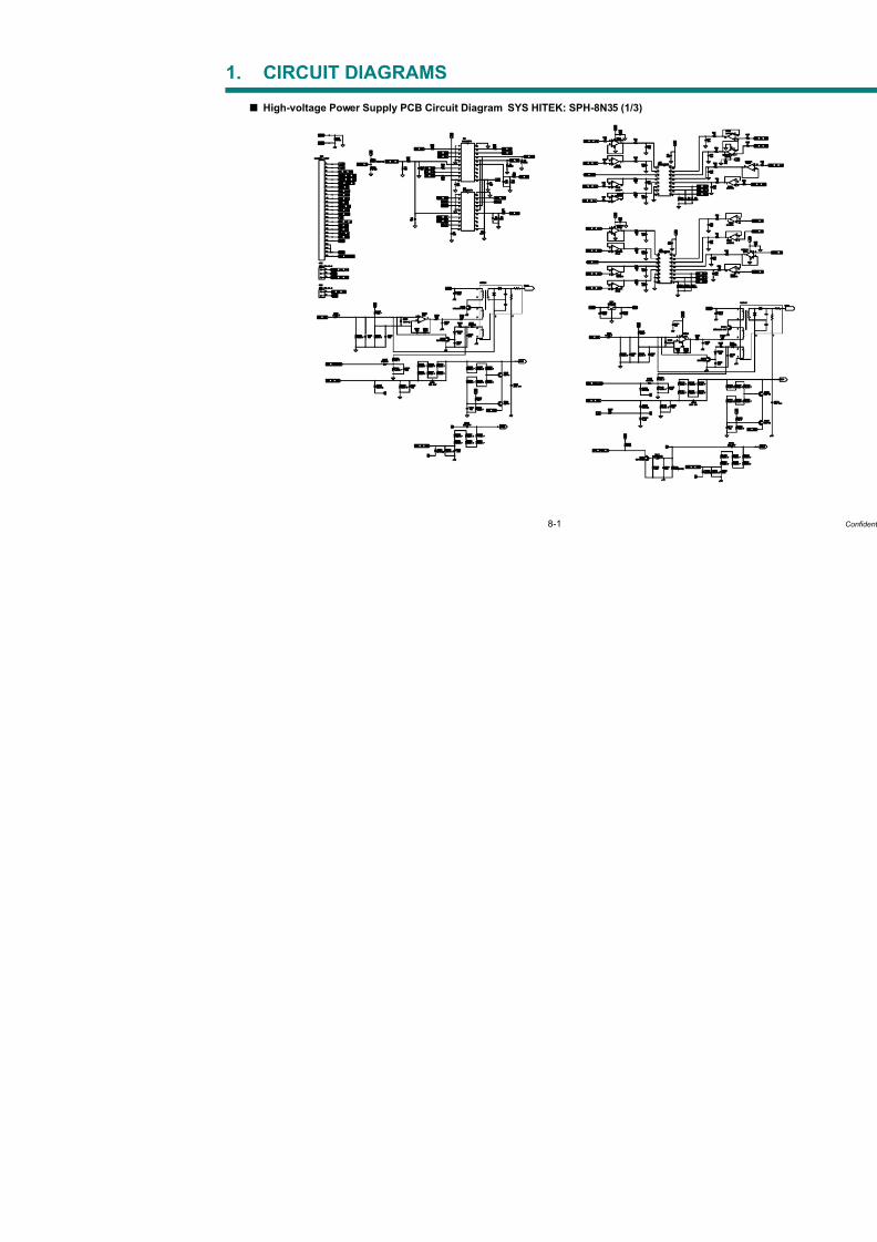
7/18/2019 Brother Mfc 9125cn 9325cw en 5694 Mfp Sm
http://slidepdf.com/reader/full/brother-mfc-9125cn-9325cw-en-5694-mfp-sm 520/597
8-1
1. CIRCUIT DIAGRAMS
High-voltage Power Supply PCB Circuit Diagram SYS HITEK: SPH-8N35 (1/3)

7/18/2019 Brother Mfc 9125cn 9325cw en 5694 Mfp Sm
http://slidepdf.com/reader/full/brother-mfc-9125cn-9325cw-en-5694-mfp-sm 521/597
8-2
High-voltage Power Supply PCB Circuit Diagram SYS HITEK: SPH-8N35 (2/3)
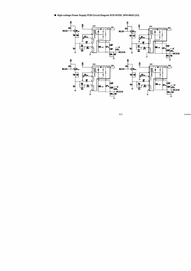
7/18/2019 Brother Mfc 9125cn 9325cw en 5694 Mfp Sm
http://slidepdf.com/reader/full/brother-mfc-9125cn-9325cw-en-5694-mfp-sm 522/597
8-3
High-voltage Power Supply PCB Circuit Diagram SYS HITEK: SPH-8N35 (3/3)

7/18/2019 Brother Mfc 9125cn 9325cw en 5694 Mfp Sm
http://slidepdf.com/reader/full/brother-mfc-9125cn-9325cw-en-5694-mfp-sm 523/597
8-4
High-voltage Power Supply PCB Circuit Diagram MURATA: MPH3316 (1/3)
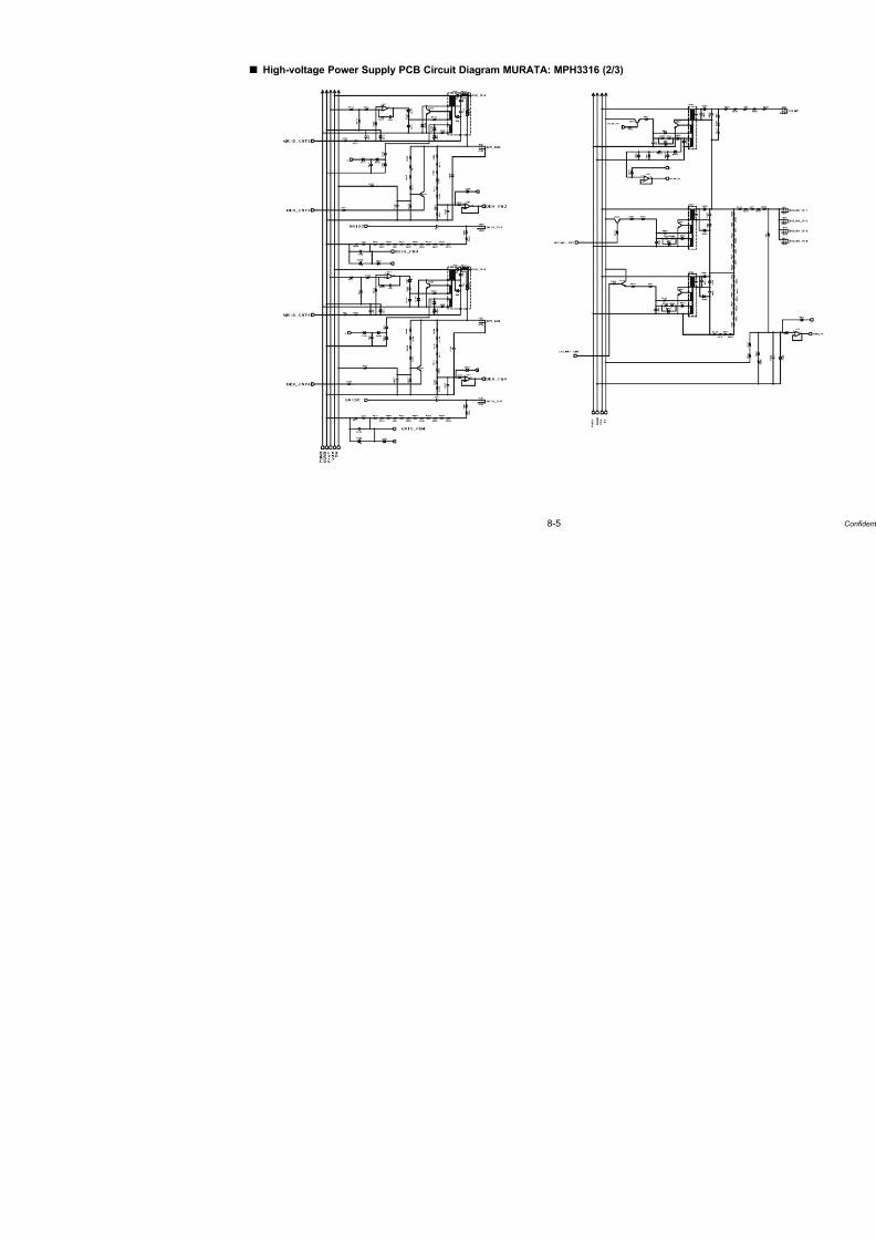
7/18/2019 Brother Mfc 9125cn 9325cw en 5694 Mfp Sm
http://slidepdf.com/reader/full/brother-mfc-9125cn-9325cw-en-5694-mfp-sm 524/597
8-5
High-voltage Power Supply PCB Circuit Diagram MURATA: MPH3316 (2/3)

7/18/2019 Brother Mfc 9125cn 9325cw en 5694 Mfp Sm
http://slidepdf.com/reader/full/brother-mfc-9125cn-9325cw-en-5694-mfp-sm 525/597
8-6
High-voltage Power Supply PCB Circuit Diagram MURATA: MPH3316 (3/3)
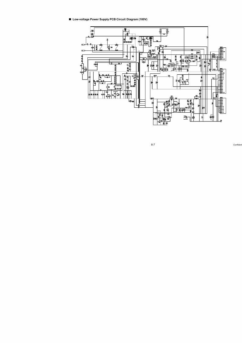
7/18/2019 Brother Mfc 9125cn 9325cw en 5694 Mfp Sm
http://slidepdf.com/reader/full/brother-mfc-9125cn-9325cw-en-5694-mfp-sm 526/597
8-7
Low-voltage Power Supply PCB Circuit Diagram (100V)

7/18/2019 Brother Mfc 9125cn 9325cw en 5694 Mfp Sm
http://slidepdf.com/reader/full/brother-mfc-9125cn-9325cw-en-5694-mfp-sm 527/597
8-8
Low-voltage Power Supply PCB Circuit Diagram (200V)
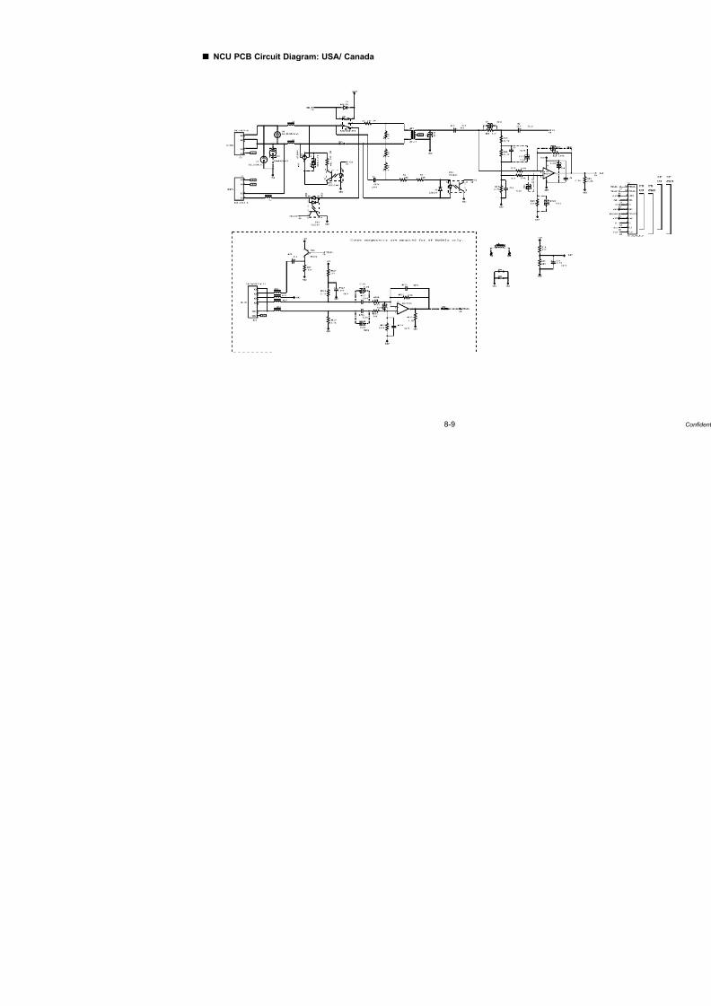
7/18/2019 Brother Mfc 9125cn 9325cw en 5694 Mfp Sm
http://slidepdf.com/reader/full/brother-mfc-9125cn-9325cw-en-5694-mfp-sm 528/597
8-9
NCU PCB Circuit Diagram: USA/ Canada

7/18/2019 Brother Mfc 9125cn 9325cw en 5694 Mfp Sm
http://slidepdf.com/reader/full/brother-mfc-9125cn-9325cw-en-5694-mfp-sm 529/597
8-10
NCU PCB Circuit Diagram: Europe/Asia/Oceania/China

7/18/2019 Brother Mfc 9125cn 9325cw en 5694 Mfp Sm
http://slidepdf.com/reader/full/brother-mfc-9125cn-9325cw-en-5694-mfp-sm 530/597
8-11
NCU PCB Circuit Diagram: South Africa/Gulf
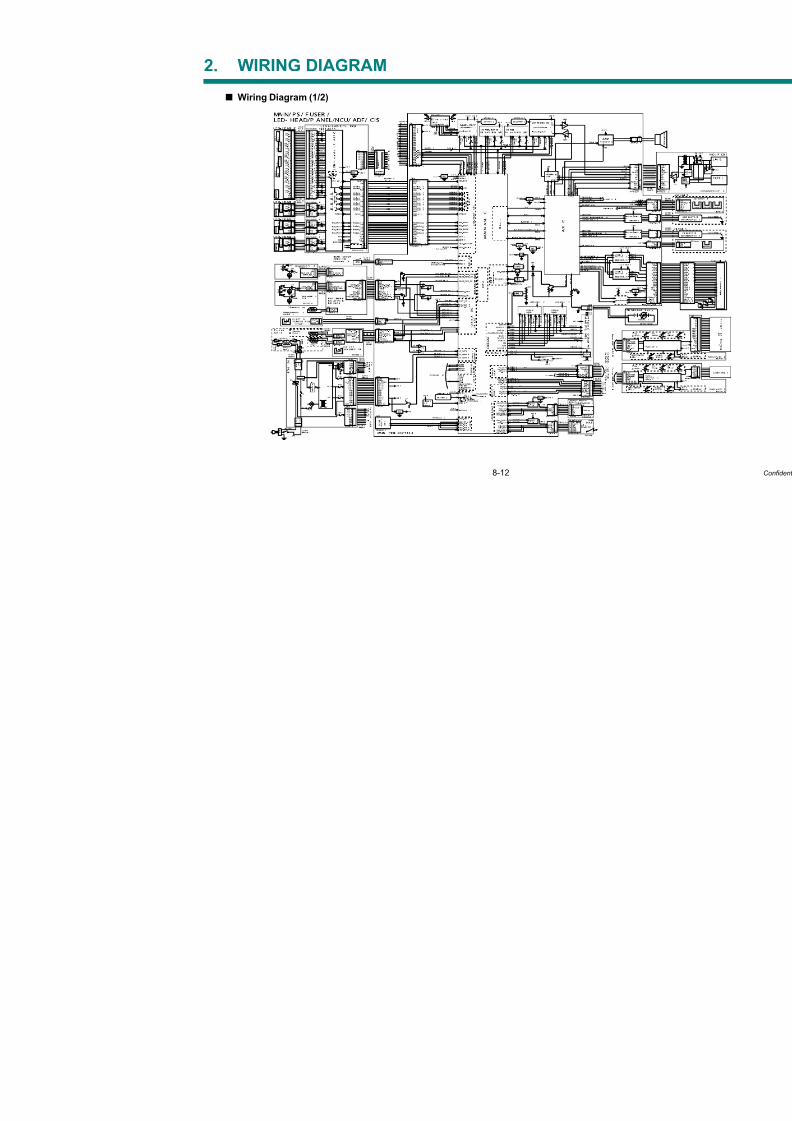
7/18/2019 Brother Mfc 9125cn 9325cw en 5694 Mfp Sm
http://slidepdf.com/reader/full/brother-mfc-9125cn-9325cw-en-5694-mfp-sm 531/597
8-12
2. WIRING DIAGRAM
Wiring Diagram (1/2)
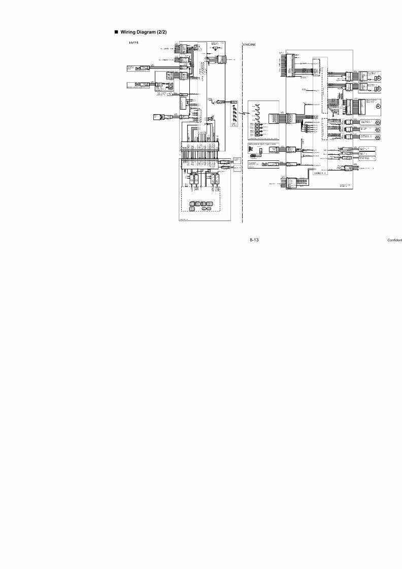
7/18/2019 Brother Mfc 9125cn 9325cw en 5694 Mfp Sm
http://slidepdf.com/reader/full/brother-mfc-9125cn-9325cw-en-5694-mfp-sm 532/597
8-13
Wiring Diagram (2/2)

7/18/2019 Brother Mfc 9125cn 9325cw en 5694 Mfp Sm
http://slidepdf.com/reader/full/brother-mfc-9125cn-9325cw-en-5694-mfp-sm 533/597
Confidential
APPENDIX 1.WORKER SWITCH (WSW)
This appendix describes the functions of the worker switches.
Each of the firmware switches has eight selectors. You should not allow end users to access all of those
selectors, but you can allow them to access user-accessible selectors which are shaded in the worker
switch tables in this appendix.
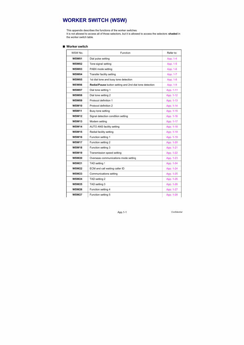
7/18/2019 Brother Mfc 9125cn 9325cw en 5694 Mfp Sm
http://slidepdf.com/reader/full/brother-mfc-9125cn-9325cw-en-5694-mfp-sm 534/597
App.1-1 Confidential
WORKER SWITCH (WSW)
This appendix describes the functions of the worker switches.
It is not allowed to access all of those selectors, but it is allowed to access the selectors shaded in
the worker switch table.
Worker switch
WSW No. Function Refer to:
WSW01 Dial pulse setting App. 1-4
WSW02 Tone signal setting App. 1-5
WSW03 PABX mode setting App. 1-6
WSW04 Transfer facility setting App. 1-7
WSW05 1st dial tone and busy tone detection App. 1-8
WSW06 Redial/Pause button setting and 2nd dial tone detection App. 1-9
WSW07 Dial tone setting 1 App. 1-11
WSW08 Dial tone setting 2 App. 1-12
WSW09 Protocol definition 1 App. 1-13
WSW10 Protocol definition 2 App. 1-14
WSW11 Busy tone setting App. 1-15
WSW12 Signal detection condition setting App. 1-16
WSW13 Modem setting App. 1-17
WSW14 AUTO ANS facility setting App. 1-18
WSW15 Redial facility setting App. 1-19
WSW16 Function setting 1 App. 1-19
WSW17 Function setting 2 App. 1-20
WSW18 Function setting 3 App. 1-21
WSW19 Transmission speed setting App. 1-22
WSW20 Overseas communications mode setting App. 1-23
WSW21 TAD setting 1 App. 1-24
WSW22 ECM and call waiting caller ID App. 1-24
WSW23 Communications setting App. 1-25
WSW24 TAD setting 2 App. 1-26
WSW25 TAD setting 3 App. 1-26
WSW26 Function setting 4 App. 1-27
WSW27 Function setting 5 App. 1-28

7/18/2019 Brother Mfc 9125cn 9325cw en 5694 Mfp Sm
http://slidepdf.com/reader/full/brother-mfc-9125cn-9325cw-en-5694-mfp-sm 535/597
App.1-2 Confidential
WSW28 Function setting 6 App. 1-28
WSW29 Function setting 7 App. 1-29
WSW30 Function setting 8 App. 1-29
WSW31 Function setting 9 App. 1-30
WSW32 Function setting 10 App. 1-30
WSW33 Function setting 11 App. 1-31
WSW34 Function setting 12 App. 1-31
WSW35 Function setting 13 App. 1-31
WSW36 Function setting 14 App. 1-32
WSW37 Function setting 15 App. 1-33
WSW38 V.34 transmission settings App. 1-34
WSW39 V.34 transmission speed App. 1-35
WSW40 V.34 modem settings App. 1-36
WSW41 ON-duration of the scanning light source App. 1-37
WSW42 Internet mail settings App. 1-37
WSW43 Function setting 16 App. 1-38
WSW44 Speeding up scanning-1 App. 1-38
WSW45 Speeding up scanning-2 App. 1-39
WSW46 Monitor of power ON/OFF state and parallel port kept at high App. 1-40
WSW47 Switching between high- and full-speed USB App. 1-41
WSW48 USB setup latency App. 1-41
WSW49 End-of-copying beep and print in black App. 1-42
WSW50 SDAA settings App. 1-42
WSW51 Function setting 17 App. 1-43
WSW52 Function setting 18 App. 1-43
WSW53 Function setting 19 App. 1-43
WSW54 Function setting 20 App. 1-44
WSW55 Interval of time requred for the developing bias voltage correction App. 1-45
WSW56 Function setting 21 App. 1-45
WSW57 Function setting 22 App. 1-46
WSW58 Function setting 23 App. 1-46
WSW59 Function setting 24 App. 1-47
WSW60 Function setting 25 App. 1-48
WSW No. Function Refer to:

7/18/2019 Brother Mfc 9125cn 9325cw en 5694 Mfp Sm
http://slidepdf.com/reader/full/brother-mfc-9125cn-9325cw-en-5694-mfp-sm 536/597
App.1-3 Confidential
WSW61 Scanning light intensity to judge to be stable 1 App. 1-49
WSW62 Scanning light intensity to judge to be stable 2 App. 1-49
WSW63 Function setting 26 App. 1-50
WSW64 Setting the language/Default paper size App. 1-51
WSW65 Setting the paper support App. 1-51
WSW66 Reserved (Change of the setting is prohibited) App. 1-52
WSW67 Reserved (Change of the setting is prohibited) App. 1-52
WSW68 Reserved (Change of the setting is prohibited) App. 1-52
WSW69 Reserved (Change of the setting is prohibited) App. 1-52
WSW70 Reserved (Change of the setting is prohibited) App. 1-52
WSW71 Reserved (Change of the setting is prohibited) App. 1-52
WSW72 Reserved (Change of the setting is prohibited) App. 1-53
WSW73 Reserved (Change of the setting is prohibited) App. 1-53
WSW74 ADF stop control App. 1-53
WSW75 Paper feeding parameter for turning the document counter
when the machine takes action duplex scanning
App. 1-53
WSW76 The limited number of the documents in reverse for paper
ejection of the simplex scanning from ADF
App. 1-54
WSW77 The limited number of the documents in reverse for paperejection of the duplex scanning from ADF
App. 1-54
WSW No. Function Refer to:
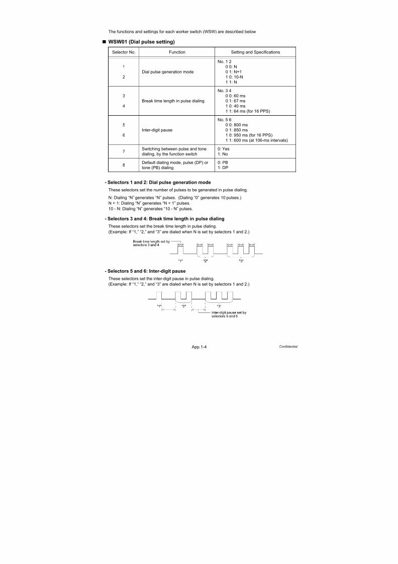
7/18/2019 Brother Mfc 9125cn 9325cw en 5694 Mfp Sm
http://slidepdf.com/reader/full/brother-mfc-9125cn-9325cw-en-5694-mfp-sm 537/597
App.1-4 Confidential
The functions and settings for each worker switch (WSW) are described below;
WSW01 (Dial pulse setting)
- Selectors 1 and 2: Dial pulse generation mode
These selectors set the number of pulses to be generated in pulse dialing.
N: Dialing “N” generates “N” pulses. (Dialing “0” generates 10 pulses.)
N + 1: Dialing “N” generates “N + 1” pulses.
10 - N: Dialing “N” generates “10 - N” pulses.
- Selectors 3 and 4: Break time length in pulse dialing
These selectors set the break time length in pulse dialing.
(Example: If “1,” “2,” and “3” are dialed when N is set by selectors 1 and 2.)
- Selectors 5 and 6: Inter-digit pause
These selectors set the inter-digit pause in pulse dialing.
(Example: If “1,” “2,” and “3” are dialed when N is set by selectors 1 and 2.)
Selector No. Function Setting and Specifications
1
2
Dial pulse generation mode
No. 1 20 0: N
0 1: N+1
1 0: 10-N
1 1: N
3
4
Break time length in pulse dialing
No. 3 4
0 0: 60 ms
0 1: 67 ms
1 0: 40 ms
1 1: 64 ms (for 16 PPS)
5
6
Inter-digit pause
No. 5 6
0 0: 800 ms0 1: 850 ms
1 0: 950 ms (for 16 PPS)
1 1: 600 ms (at 106-ms intervals)
7Switching between pulse and tone
dialing, by the function switch
0: Yes
1: No
8Default dialing mode, pulse (DP) or
tone (PB) dialing
0: PB
1: DP

7/18/2019 Brother Mfc 9125cn 9325cw en 5694 Mfp Sm
http://slidepdf.com/reader/full/brother-mfc-9125cn-9325cw-en-5694-mfp-sm 538/597
App.1-5 Confidential
- Selector 7: Switching between pulse and tone dialing, by the function switch
This selector determines whether or not the dialing mode can be switched between the pulse (DP)
and tone (PB) dialing by using the function switch.
- Selector 8: Default dialing mode, pulse (DP) or tone (PB) dialing
This selector sets the default dialing mode (pulse dialing or tone dialing) which can be changed bythe function switch. If the user switches it with the function switch when selector 7 is set to “0,” the
setting specified by this selector will also be switched automatically.
WSW02 (Tone signal setting)
- Selectors 1 through 4: Tone signal transmission time length and Min. pause in tone dialing
These selectors set the tone signal transmission time length and minimum pause in tone dialing.
(Example: If “1,” “2,” “3,” “4,” and “5” are dialed.)
- Selectors 5 through 8: Attenuator for pseudo ring backtone to the line
These selectors are used to adjust the sound volume of a ring backtone in the F/T mode, an on-hold
sound, or a beep generated as a signal during remote control operation or at the start of ICM recording.
The larger the value specified by these selectors, the greater the attenuation.
Selector No. Function Setting and Specifications
1
2
Tone signal transmission time length
No. 1 2
0 0: 70 ms
0 1: 80 ms
1 0: 90 ms1 1: 100 ms
3
4
Min. pause in tone dialing
No. 3 4
0 0: 70 ms
0 1: 80 ms
1 0: 90 ms
1 1: 140 ms
5
|
8
Attenuator for pseudo ring backtone
to the line (selectable in the range of
0-15 dB, in 1 dB increments)
0: 0 dB 1: 8 dB
0: 0 dB 1: 4 dB
0: 0 dB 1: 2 dB
0: 0 dB 1: 1 dB

7/18/2019 Brother Mfc 9125cn 9325cw en 5694 Mfp Sm
http://slidepdf.com/reader/full/brother-mfc-9125cn-9325cw-en-5694-mfp-sm 539/597
App.1-6 Confidential
WSW03 (PABX mode setting)
* PABX: Private automatic branch exchange
- Selectors 1 and 5: CNG detection when sharing a modular wall socket with a telephone
These selectors determine whether or not the machine detects a CNG signal when a line is
connected to a telephone sharing a modular wall socket with the machine. Upon detection of CNG
signals by the number of cycles specified by these selectors, the machine interprets CNG as an
effective signal and then starts FAX reception.
Selector No. Function Setting and Specifications
1CNG detection when sharing a
modular wall socket with a telephone
0: A
1: B
2
|
4
Detection time length of PABX* dial
tone, required for starting dialing
(Not used.)
5CNG detection when sharing a
modular wall socket with a telephone
0: A
1: B
6
7
Dial tone detection in PABX*
(Not used.)
8 Not used.
Note:
Selectors 2 through 4, 6 and 7 are not applicable where no PABX is installed.
Selector CycleNo. 1 No. 5
0 (A) 0 (A) 0.5 cycle
0 (A) 1 (B) 1.0 cycle
1 (A) 0 (A) 1.5 cycle
1 (B) 1 (B) 2.0 cycle

7/18/2019 Brother Mfc 9125cn 9325cw en 5694 Mfp Sm
http://slidepdf.com/reader/full/brother-mfc-9125cn-9325cw-en-5694-mfp-sm 540/597

7/18/2019 Brother Mfc 9125cn 9325cw en 5694 Mfp Sm
http://slidepdf.com/reader/full/brother-mfc-9125cn-9325cw-en-5694-mfp-sm 541/597
App.1-8 Confidential
WSW05 (1st dial tone and busy tone detection)
- Selectors 1 through 3: 1st dial tone detection
These selectors activate or deactivate the 1st dial tone detection function which detects the
1st dial tone issued from the PSTN when a line is connected to the PSTN.
Setting all of these selectors to “1” activates the dial tone detection function so that the machine
starts dialing upon detection of a dial tone when a line is connected. (However, in those countries
which support no dial tone detection function, e.g., in the USA, setting these selectors to “1” makes
the machine start dialing after a WAIT of 3.5 seconds.) For the detecting conditions of the 1st dial
tone, refer to WSW07 and WSW08.
Other setting combinations deactivate the dial tone detection function so that the machine starts
dialing after the specified WAIT (3.5, 7.0, 10.5, 14.0, 17.5, 21.0, or 24.5 seconds) without detection
of a dial tone when a line is connected to the PSTN.
- Selector 4: Max. pause time allowable for remote ID code detection
This selector sets the maximum pause time allowable for detecting the second digit of a remote ID
code after detection of the first digit in remote reception.
If selector 4 is set to “0” (2 seconds), for instance, only a remote ID code whose second digit is
detected within 2 seconds after detection of the first digit will become effective so as to activate the
remote function.
Selector No. Function Setting and Specifications
1
l
3
1st dial tone detection
No. 1 2 3
0 0 0: 3.5 sec. wait
0 0 1: 7.0 sec. wait0 1 0: 10.5 sec. wait
0 1 1: 14.0 sec. wait
1 0 0: 17.5 sec. wait
1 0 1: 21.0 sec. wait
1 1 0: 24.5 sec. wait
1 1 1: Detection (Without wait)
4Max. pause time allowable for remote
ID code detection
0: 2 sec.
1: 1 sec.
5
6Busy tone detection in auto-maticsending mode
No. 5 6
0 0: No detection
0 1: Detection only after dialing1 0: No detection
1 1: Detection before and after
dialing
7Busy tone detection in auto-matic
receiving mode
0: Yes
1: No
8 Not used.
Note:
Selectors 5 through 7 are not applicable in those countries where no busy tone detection is supported.
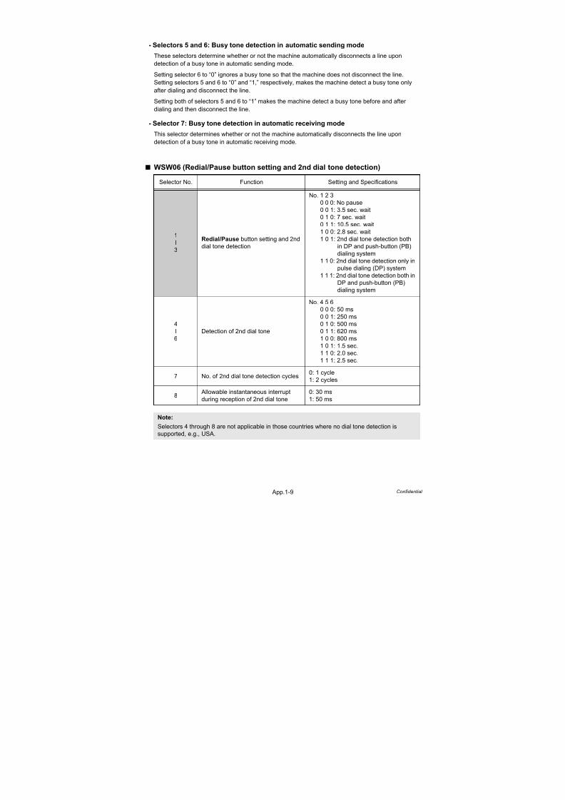
7/18/2019 Brother Mfc 9125cn 9325cw en 5694 Mfp Sm
http://slidepdf.com/reader/full/brother-mfc-9125cn-9325cw-en-5694-mfp-sm 542/597
App.1-9 Confidential
- Selectors 5 and 6: Busy tone detection in automatic sending mode
These selectors determine whether or not the machine automatically disconnects a line upon
detection of a busy tone in automatic sending mode.
Setting selector 6 to “0” ignores a busy tone so that the machine does not disconnect the line.
Setting selectors 5 and 6 to “0” and “1,” respectively, makes the machine detect a busy tone only
after dialing and disconnect the line.
Setting both of selectors 5 and 6 to “1” makes the machine detect a busy tone before and after
dialing and then disconnect the line.
- Selector 7: Busy tone detection in automatic receiving mode
This selector determines whether or not the machine automatically disconnects the line upon
detection of a busy tone in automatic receiving mode.
WSW06 (Redial/Pause button setting and 2nd dial tone detection)
Selector No. Function Setting and Specifications
1
l
3
Redial/Pause button setting and 2nd
dial tone detection
No. 1 2 3
0 0 0: No pause
0 0 1: 3.5 sec. wait
0 1 0: 7 sec. wait
0 1 1: 10.5 sec. wait
1 0 0: 2.8 sec. wait
1 0 1: 2nd dial tone detection both
in DP and push-button (PB)
dialing system
1 1 0: 2nd dial tone detection only in
pulse dialing (DP) system1 1 1: 2nd dial tone detection both in
DP and push-button (PB)
dialing system
4
l
6
Detection of 2nd dial tone
No. 4 5 6
0 0 0: 50 ms
0 0 1: 250 ms
0 1 0: 500 ms
0 1 1: 620 ms
1 0 0: 800 ms
1 0 1: 1.5 sec.
1 1 0: 2.0 sec.
1 1 1: 2.5 sec.
7 No. of 2nd dial tone detection cycles0: 1 cycle
1: 2 cycles
8 Allowable instantaneous interrupt
during reception of 2nd dial tone
0: 30 ms
1: 50 ms
Note:
Selectors 4 through 8 are not applicable in those countries where no dial tone detection is
supported, e.g., USA.
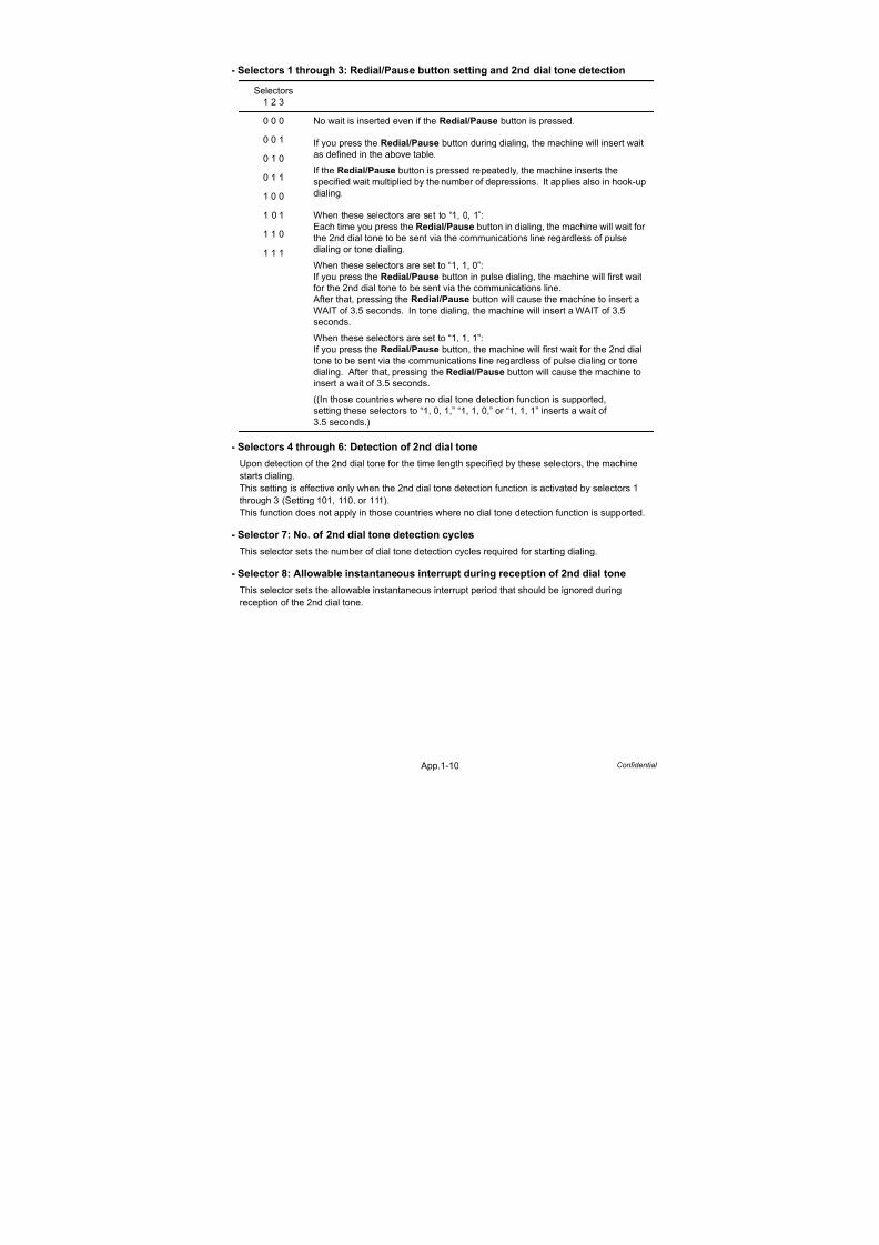
7/18/2019 Brother Mfc 9125cn 9325cw en 5694 Mfp Sm
http://slidepdf.com/reader/full/brother-mfc-9125cn-9325cw-en-5694-mfp-sm 543/597
App.1-10 Confidential
- Selectors 1 through 3: Redial/Pause button setting and 2nd dial tone detection
- Selectors 4 through 6: Detection of 2nd dial tone
Upon detection of the 2nd dial tone for the time length specified by these selectors, the machine
starts dialing.
This setting is effective only when the 2nd dial tone detection function is activated by selectors 1
through 3 (Setting 101, 110, or 111).
This function does not apply in those countries where no dial tone detection function is supported.
- Selector 7: No. of 2nd dial tone detection cycles
This selector sets the number of dial tone detection cycles required for starting dialing.
- Selector 8: Allowable instantaneous interrupt during reception of 2nd dial tone
This selector sets the allowable instantaneous interrupt period that should be ignored during
reception of the 2nd dial tone.
Selectors
1 2 3
0 0 0 No wait is inserted even if the Redial/Pause button is pressed.
0 0 1 If you press the Redial/Pause button during dialing, the machine will insert waitas defined in the above table.
If the Redial/Pause button is pressed repeatedly, the machine inserts the
specified wait multiplied by the number of depressions. It applies also in hook-up
dialing.
0 1 0
0 1 1
1 0 0
1 0 1 When these selectors are set to “1, 0, 1”:
Each time you press the Redial/Pause button in dialing, the machine will wait for
the 2nd dial tone to be sent via the communications line regardless of pulse
dialing or tone dialing.
When these selectors are set to “1, 1, 0”:
If you press the Redial/Pause button in pulse dialing, the machine will first waitfor the 2nd dial tone to be sent via the communications line.
After that, pressing the Redial/Pause button will cause the machine to insert a
WAIT of 3.5 seconds. In tone dialing, the machine will insert a WAIT of 3.5
seconds.
When these selectors are set to “1, 1, 1”:
If you press the Redial/Pause button, the machine will first wait for the 2nd dial
tone to be sent via the communications line regardless of pulse dialing or tone
dialing. After that, pressing the Redial/Pause button will cause the machine to
insert a wait of 3.5 seconds.
((In those countries where no dial tone detection function is supported,
setting these selectors to “1, 0, 1,” “1, 1, 0,” or “1, 1, 1” inserts a wait of
3.5 seconds.)
1 1 0
1 1 1

7/18/2019 Brother Mfc 9125cn 9325cw en 5694 Mfp Sm
http://slidepdf.com/reader/full/brother-mfc-9125cn-9325cw-en-5694-mfp-sm 544/597
App.1-11 Confidential
WSW07 (Dial tone setting 1)
- Selectors 1 and 2: Dial tone frequency band control
These selectors set the frequency band for the 1st dial tone and busy tone (before dialing) to be
detected. This setting is effective only when selectors 1 through 3 on WSW05 are set to “1,1,1.”
- Selectors 4 through 6: 2nd dial tone detection level
These selectors set the detection level of the 2nd dial tone.
- Selector 7: Allowable instantaneous interrupt during reception of 1st dial tone
This selector sets the allowable instantaneous interrupt period that should be ignored during
reception of the 1st dial tone.
Selector No. Function Setting and Specifications
1
2Dial tone frequency band control
No. 1 2
0 0: Narrows by 10 Hz
0 1: Initial value1 0: Widens by 10 Hz
1 1: Widens by 10 Hz
3 Line current detection (Not used.)
4
l
6
2nd dial tone detection level
(Z = 600 Ω)
No. 4 5 6
0 0 0: -21 dBm
0 0 1: -24 dBm
0 1 0: -27 dBm
0 1 1: -30 dBm
1 0 0: -33 dBm
1 0 1: -36 dBm
1 1 0: -39 dBm1 1 1: -42 dBm
7 Allowable instantaneous interrupt
during reception of 1st dial tone
0: 30 ms
1: 50 ms
8 Not used.
Note:
Selectors 1, 2, 4 through 7 are not applicable in those countries where no dial tone or line current
detection is supported, e.g., USA.

7/18/2019 Brother Mfc 9125cn 9325cw en 5694 Mfp Sm
http://slidepdf.com/reader/full/brother-mfc-9125cn-9325cw-en-5694-mfp-sm 545/597
App.1-12 Confidential
WSW08 (Dial tone setting 2)
- Selectors 1 through 3: 1st dial tone detection time length
Upon detection of the 1st dial tone for the time length set by these selectors, the machine starts
dialing. This setting is effective only when selectors 1 through 3 on WSW05 are set to “1,1,1.”
- Selectors 4 and 5: Time-out length for 1st and 2nd dial tone detection
These selectors set the time-out length for the 1st and 2nd dial tone detection so that the machine
waits dial tone input for the specified time length and disconnects itself from the line when no dial
tone is inputted.
Selector No. Function Setting and Specifications
1
l
3
1st dial tone detection time length
No. 1 2 3
0 0 0: 50 ms
0 0 1: 250 ms0 1 0: 500 ms
0 1 1: 620 ms
1 0 0: 800 ms
1 0 1: 1.5 sec.
1 1 0: 2.0 sec.
1 1 1: 2.5 sec.
4
5
Time-out length for 1st and 2nd dial
tone detection
No. 4 5
0 0: 10 sec.
0 1: 20 sec.
1 0: 15 sec.
1 1: 30 sec.
6
l
8
Detection level of 1st dial tone and
busy tone before dialing
No. 6 7 8
0 0 0: -21 dBm
0 0 1: -24 dBm
0 1 0: -27 dBm
0 1 1: -30 dBm
1 0 0: -33 dBm
1 0 1: -36 dBm
1 1 0: -39 dBm
1 1 1: -42 dBm
Note:
The WSW08 is not applicable in those countries where no dial tone detection is supported, e.g.,USA.

7/18/2019 Brother Mfc 9125cn 9325cw en 5694 Mfp Sm
http://slidepdf.com/reader/full/brother-mfc-9125cn-9325cw-en-5694-mfp-sm 546/597
App.1-13 Confidential
WSW09 (Protocol definition 1)
- Selector 1: Frame length selectionUsually a single frame consists of 256 octets (1 octet = 8 bits). For communications lines with higher bit
error rate, however, set selector 1 to “1” so that the machine can divide a message into 64-octet frames.
Remarks: The error correction mode (ECM) is a facsimile transmission manner in which the machine
divides a message into frames for transmission so that if any data error occurs on the
transmission line, the machine retransmits only those frames containing the error data .
- Selector 2: Use of non-standard commands
If this selector is set to “0,” the machine can use non-standard commands (the machine's
native-mode commands, e.g., NSF, NSC, and NSS) for communications. If it is set to “1,” the
machine will use standard commands only.
- Selectors 3 and 4: No. of retries
These selectors set the number of retries in each specified modem transmission speed.
- Selector 5: T5 timer
This selector sets the time length for the T5 timer.
- Selector 6: T1 timer
This selector sets the time length for the T1 timer.
- Selectors 7 and 8: Timeout for response from the called station in automatic sending mode
If the machine (calling station) receives no response (no G3 command) from the called terminal in
automatic sending mode for the period specified by these selectors, it disconnects the line.
Selector No. Function Setting and Specifications
1 Frame length selection0: 256 octets
1: 64 octets
2 Use of non-standard commands 0: Allowed1: Prohibited
3
4
No. of retries
No. 3 4
0 0: 4 times
0 1: 3 times
1 0: 2 times
1 1: 1 times
5 T5 timer 0: 300 sec.
1: 60 sec.
6 T1 timer 0: 35 sec.
1: 40 sec.
7
8
Timeout for response from the called
station in automatic sending mode
No. 7 8
0 0: 55 sec.
(in USA and Canadian models)
60 sec.
(in other models)
0 1: 140 sec.
1 0: 90 sec.
1 1: 35 sec.
Note:
Selectors 1 through 5 are not applicable in those models which do not support ECM.
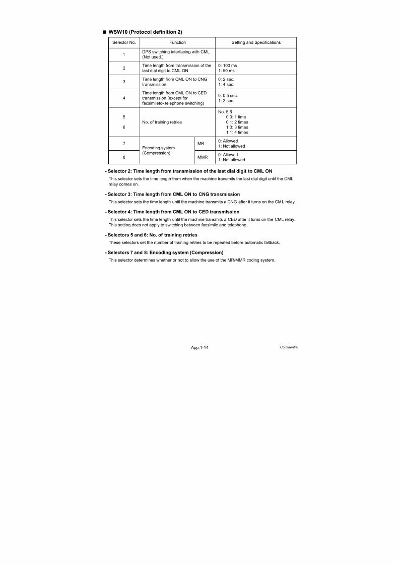
7/18/2019 Brother Mfc 9125cn 9325cw en 5694 Mfp Sm
http://slidepdf.com/reader/full/brother-mfc-9125cn-9325cw-en-5694-mfp-sm 547/597
App.1-14 Confidential
WSW10 (Protocol definition 2)
- Selector 2: Time length from transmission of the last dial digit to CML ON
This selector sets the time length from when the machine transmits the last dial digit until the CML
relay comes on.
- Selector 3: Time length from CML ON to CNG transmission
This selector sets the time length until the machine transmits a CNG after it turns on the CML relay.
- Selector 4: Time length from CML ON to CED transmission
This selector sets the time length until the machine transmits a CED after it turns on the CML relay.
This setting does not apply to switching between facsimile and telephone.
- Selectors 5 and 6: No. of training retries
These selectors set the number of training retries to be repeated before automatic fallback.
- Selectors 7 and 8: Encoding system (Compression)This selector determines whether or not to allow the use of the MR/MMR coding system.
Selector No. Function Setting and Specifications
1DPS switching interfacing with CML
(Not used.)
2Time length from transmission of the
last dial digit to CML ON
0: 100 ms
1: 50 ms
3Time length from CML ON to CNG
transmission
0: 2 sec.
1: 4 sec.
4
Time length from CML ON to CED
transmission (except for
facsimileto- telephone switching)
0: 0.5 sec.
1: 2 sec.
5
6
No. of training retries
No. 5 6
0 0: 1 time
0 1: 2 times
1 0: 3 times1 1: 4 times
7Encoding system
(Compression)
MR0: Allowed
1: Not allowed
8 MMR0: Allowed
1: Not allowed

7/18/2019 Brother Mfc 9125cn 9325cw en 5694 Mfp Sm
http://slidepdf.com/reader/full/brother-mfc-9125cn-9325cw-en-5694-mfp-sm 548/597
App.1-15 Confidential
WSW11 (Busy tone setting)
- Selectors 1 and 2: Busy tone frequency band control
These selectors set the frequency band for busy tone to be detected.
- Selectors 3 through 8: ON/OFF time length ranges for busy tone
These selectors set the ON and OFF time length ranges for busy tone to be detected. If more thanone selector is set to “1,” the ranges become wider. For example, if selectors 4 and 5 are set to “1,”
the ON and OFF time length ranges are from 175 to 600 ms.
Selector No. Function Setting and Specifications
1
2Busy tone frequency band control
No. 1 2
0 0: Narrows by 10 Hz
0 1: Initial value1 0: Widens by 10 Hz
1 1: Widens by 10 Hz
3
ON/OFF time length ranges for busy
tone (More than one setting allowed)
1: 250-750/250-750 ms
4 1: 400-600/400-600 ms
5 1: 175-440/175-440 ms
6 1: 100-1000/17-660 ms
7 1: 110-410/320-550 ms
8 1: 100-660/100-660 ms
Note:
- WSW11 is not applicable in those countries where no busy tone detection is supported.
- The setting of WSW11 is effective only when selectors 5 and 6 on WSW05 are set to “0, 1” or
“1, 1” (Busy tone detection).

7/18/2019 Brother Mfc 9125cn 9325cw en 5694 Mfp Sm
http://slidepdf.com/reader/full/brother-mfc-9125cn-9325cw-en-5694-mfp-sm 549/597
App.1-16 Confidential
WSW12 (Signal detection condition setting)
* 1,000 ms in Chinese models.
- Selectors 1 through 4: Min. detection period required for interpreting incoming
calling signal (CI) as OFFMax. detection period for incoming calling signal (CI) being OFF
If the machine detects the OFF state of a CI signal for the period greater than the value set byselectors 1 and 2 and less than the value set by selectors 3 and 4, it interprets the CI signal as OFF.
- Selectors 5 and 6: Min. detection period required for acknowledging incoming callingsignal (CI) as ON
These selectors set the period required to make the machine acknowledge itself to be called.
That is, if the machine continuously detects a CI signal with the frequency set by selectors 1 through
4 on WSW14 during the period set by these selectors 5 and 6, then it acknowledges the call.
- Selector 7: Line connection timing
If a line is connected in a ringer-ON period, FAX models equipped with SDAA circuits may
malfunction due to the ringer voltage. To make the line connection stable, this selector should beset to “0” so that a line is connected in a ringer-OFF period.
Selector No. Function Setting and Specifications
1
2
Min. detection period required for
interpreting incoming calling signal(CI) as OFF
No. 1 2
0 0: 1,500 ms
0 1: 500 ms1 0: 700 ms
1 1: 900 ms
3
4
Max. detection period for incoming
calling signal (CI) being OFF
No. 3 4
0 0: 6 sec.
0 1: 7 sec.
1 0: 9 sec.
1 1: 11 sec.
5
6
Min. detection period required for
acknowledging incoming calling
signal (CI) as ON
No. 5 6
0 0: 800 ms (1,000 ms*)
0 1: 200 ms
1 0: 250 ms1 1: 150 ms
7 Line connection timing0: Ringer-OFF period
1: Ringer-ON period
8 Not used.

7/18/2019 Brother Mfc 9125cn 9325cw en 5694 Mfp Sm
http://slidepdf.com/reader/full/brother-mfc-9125cn-9325cw-en-5694-mfp-sm 550/597
App.1-17 Confidential
WSW13 (Modem setting)
- Selectors 1 and 2: Cable equalizer
These selectors are used to improve the pass-band characteristics of analogue signals on a line.
Attenuation in the high-band frequency is greater than in the low-band frequency.
Set these selectors according to the distance from the telephone switchboard to the machine.
- Selectors 3 and 4: Reception level
These selectors set the optimum receive signal level.
- Selectors 5 through 8: Modem attenuator
These selectors are used to adjust the transmitting level attenuation of the modem when the
reception level at the remote station is improper due to line loss. This function applies for G3
protocol signals.
Setting two or more selectors to “1” produces addition of attenuation assigned to each selector.
If selector 8 on WSW23 is set to “0,” this setting is so limited that 10 dB (1 dB in France) or higher
setting only is effective.
Note that in Japan and China, 9 dB or higher and 2 dB or higher settings only are effective,respectively, regardless of whether selector 8 on WSW23 is set to “0.”
Selector No. Function Setting and Specifications
1
2Cable equalizer
No. 1 2
0 0: 0 km
0 1: 1.8 km1 0: 3.6 km
1 1: 5.6 km
3
4
Reception level
No. 3 4
0 0: -43 dBm
0 1: -47 dBm
1 0: -49 dBm
1 1: -51 dBm
5
l8
Modem attenuator
No. 5 6 7 8
0 0 0 0: 0 dB
0 0 0 1: 1 dB
0 0 1 0: 2 dB0 0 1 1: 3 dB
0 1 0 0: 4 dB
l
1 1 1 1: 15 dB
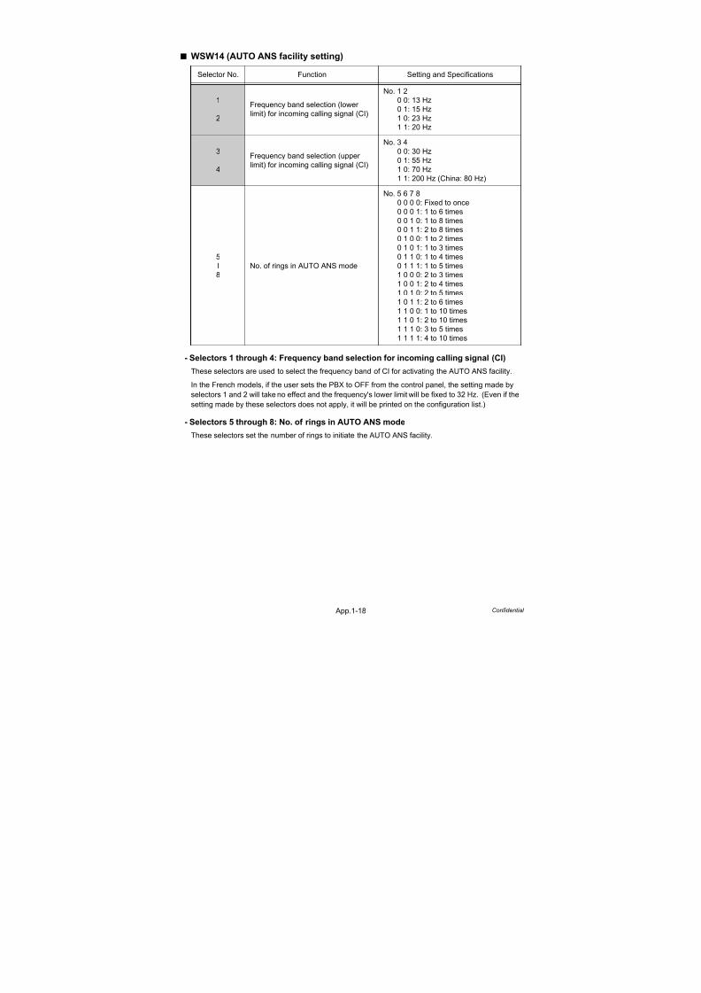
7/18/2019 Brother Mfc 9125cn 9325cw en 5694 Mfp Sm
http://slidepdf.com/reader/full/brother-mfc-9125cn-9325cw-en-5694-mfp-sm 551/597
App.1-18 Confidential
WSW14 (AUTO ANS facility setting)
- Selectors 1 through 4: Frequency band selection for incoming calling signal (CI)
These selectors are used to select the frequency band of CI for activating the AUTO ANS facility.
In the French models, if the user sets the PBX to OFF from the control panel, the setting made by
selectors 1 and 2 will take no effect and the frequency's lower limit will be fixed to 32 Hz. (Even if the
setting made by these selectors does not apply, it will be printed on the configuration list.)
- Selectors 5 through 8: No. of rings in AUTO ANS mode
These selectors set the number of rings to initiate the AUTO ANS facility.
Selector No. Function Setting and Specifications
1
2
Frequency band selection (lower
limit) for incoming calling signal (CI)
No. 1 2
0 0: 13 Hz
0 1: 15 Hz1 0: 23 Hz
1 1: 20 Hz
3
4
Frequency band selection (upper
limit) for incoming calling signal (CI)
No. 3 4
0 0: 30 Hz
0 1: 55 Hz
1 0: 70 Hz
1 1: 200 Hz (China: 80 Hz)
5
l
8
No. of rings in AUTO ANS mode
No. 5 6 7 8
0 0 0 0: Fixed to once
0 0 0 1: 1 to 6 times
0 0 1 0: 1 to 8 times0 0 1 1: 2 to 8 times
0 1 0 0: 1 to 2 times
0 1 0 1: 1 to 3 times
0 1 1 0: 1 to 4 times
0 1 1 1: 1 to 5 times
1 0 0 0: 2 to 3 times
1 0 0 1: 2 to 4 times
1 0 1 0: 2 to 5 times
1 0 1 1: 2 to 6 times
1 1 0 0: 1 to 10 times
1 1 0 1: 2 to 10 times
1 1 1 0: 3 to 5 times
1 1 1 1: 4 to 10 times

7/18/2019 Brother Mfc 9125cn 9325cw en 5694 Mfp Sm
http://slidepdf.com/reader/full/brother-mfc-9125cn-9325cw-en-5694-mfp-sm 552/597
App.1-19 Confidential
WSW15 (Redial facility setting)
- Selectors 1 through 6: Redial interval and No. of redialings
The machine redials by the number of times set by selectors 3 through 6 at intervals set by selectors
1 and 2.
- Selector 8: CRP option
If a command error occurs in the machine (calling station), the machine usually waits for three
seconds and then makes a retry three times. This CRP option is a request command that can be
sent from the called station for requesting the calling station to retry the failed command immediately.
WSW16 (Function setting 1)
- Selector 2: ITU-T (CCITT) superfine recommendation
If this selector is set to “1,” the machine communicates in ITU-T (CCITT) recommended superfine
mode (15.4 lines/mm). If it is set to “0,” it communicates in native superfine mode.
- Selector 7: Max. document length limitation
This selector is used to select the maximum length of a document to be sent.
- Selector 8: Stop/Exit button pressed during reception
If this selector is set to “1,” pressing the Stop/Exit button can stop the current receiving operation.
The received data will be lost.
Selector No. Function Setting and Specifications
1
2
Redial interval
No. 1 2
0 0: 5 min.
0 1: 1 min.
1 0: 2 min.1 1: 3 min.
3
l
6
No. of redialings
No. 3 4 5 6
0 0 0 0: 16 times
0 0 0 1: 1 times
0 0 1 0: 2 times
0 0 1 1: 3 times
l
1 1 1 1: 15 times
7 Not used.
8 CRP option0: Disable
1: Enable
Selector No. Function Setting and Specifications
1 Not used.
2ITU-T (CCITT) superfine
recommendation
0: OFF
1: ON
3
l
6
Not used.
7 Max. document length limitation0: 400 cm
1: 90 cm
8Stop/Exit button pressed during
reception
0: Not functional
1: Functional

7/18/2019 Brother Mfc 9125cn 9325cw en 5694 Mfp Sm
http://slidepdf.com/reader/full/brother-mfc-9125cn-9325cw-en-5694-mfp-sm 553/597
App.1-20 Confidential
WSW17 (Function setting 2)
- Selector 5: Calendar clock type
If this selector is set to “0” (USA), the MM/DD/YY hh:mm format applies; if it is set to “1” (Europe),
the DD/MM/YY hh:mm format applies: DD is the day, MM is the month, YY is the last two digits of
the year, hh is the hour, and mm is the minute.
- Selector 7: Non-ring reception
Setting this selector to “1” makes the machine receive calls without ringer sound if the number of
calling is set to 0.
Selector No. Function Setting and Specifications
1
2
Off-hook alarm (Not used.)
3
4
Not used.
5 Calendar clock type0: USA type
1: European type
6 Not used.
7 Non-ring reception0: OFF
1: ON
8 Not used.
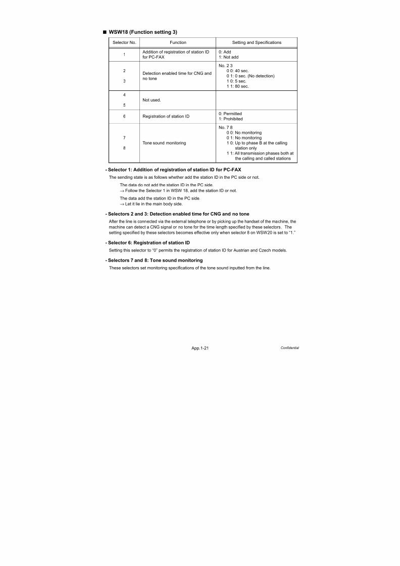
7/18/2019 Brother Mfc 9125cn 9325cw en 5694 Mfp Sm
http://slidepdf.com/reader/full/brother-mfc-9125cn-9325cw-en-5694-mfp-sm 554/597
App.1-21 Confidential
WSW18 (Function setting 3)
- Selector 1: Addition of registration of station ID for PC-FAX
The sending state is as follows whether add the station ID in the PC side or not.
The data do not add the station ID in the PC side.
→ Follow the Selector 1 in WSW 18, add the station ID or not.
The data add the station ID in the PC side.
→ Let it lie in the main body side.
- Selectors 2 and 3: Detection enabled time for CNG and no tone
After the line is connected via the external telephone or by picking up the handset of the machine, the
machine can detect a CNG signal or no tone for the time length specified by these selectors. The
setting specified by these selectors becomes effective only when selector 8 on WSW20 is set to “1.”
- Selector 6: Registration of station ID
Setting this selector to “0” permits the registration of station ID for Austrian and Czech models.
- Selectors 7 and 8: Tone sound monitoring
These selectors set monitoring specifications of the tone sound inputted from the line.
Selector No. Function Setting and Specifications
1 Addition of registration of station ID
for PC-FAX
0: Add
1: Not add
2
3
Detection enabled time for CNG and
no tone
No. 2 3
0 0: 40 sec.
0 1: 0 sec. (No detection)
1 0: 5 sec.
1 1: 80 sec.
4
5
Not used.
6 Registration of station ID0: Permitted
1: Prohibited
7
8
Tone sound monitoring
No. 7 80 0: No monitoring
0 1: No monitoring
1 0: Up to phase B at the calling
station only
1 1: All transmission phases both at
the calling and called stations
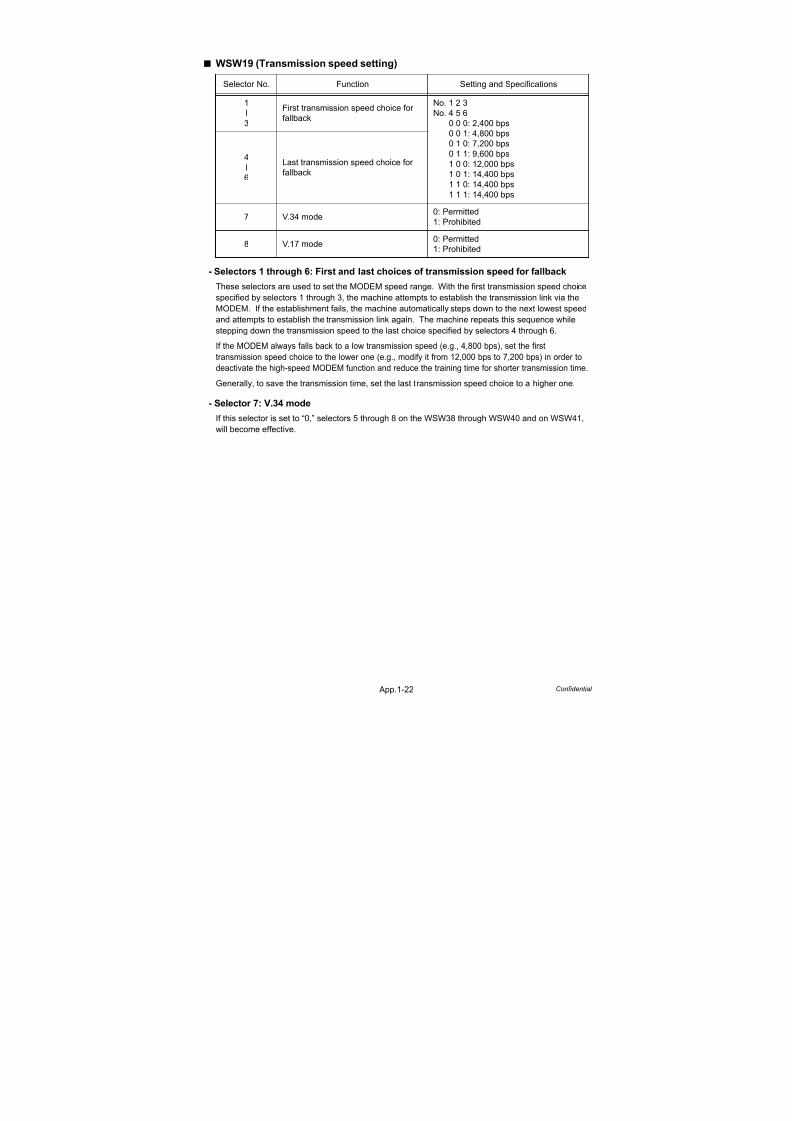
7/18/2019 Brother Mfc 9125cn 9325cw en 5694 Mfp Sm
http://slidepdf.com/reader/full/brother-mfc-9125cn-9325cw-en-5694-mfp-sm 555/597
App.1-22 Confidential
WSW19 (Transmission speed setting)
- Selectors 1 through 6: First and last choices of transmission speed for fallback
These selectors are used to set the MODEM speed range. With the first transmission speed choice
specified by selectors 1 through 3, the machine attempts to establish the transmission link via the
MODEM. If the establishment fails, the machine automatically steps down to the next lowest speed
and attempts to establish the transmission link again. The machine repeats this sequence while
stepping down the transmission speed to the last choice specified by selectors 4 through 6.
If the MODEM always falls back to a low transmission speed (e.g., 4,800 bps), set the first
transmission speed choice to the lower one (e.g., modify it from 12,000 bps to 7,200 bps) in order to
deactivate the high-speed MODEM function and reduce the training time for shorter transmission time.
Generally, to save the transmission time, set the last transmission speed choice to a higher one.
- Selector 7: V.34 mode
If this selector is set to “0,” selectors 5 through 8 on the WSW38 through WSW40 and on WSW41,
will become effective.
Selector No. Function Setting and Specifications
1
l
3
First transmission speed choice for
fallback
No. 1 2 3
No. 4 5 6
0 0 0: 2,400 bps0 0 1: 4,800 bps
0 1 0: 7,200 bps
0 1 1: 9,600 bps
1 0 0: 12,000 bps
1 0 1: 14,400 bps
1 1 0: 14,400 bps
1 1 1: 14,400 bps
4
l
6
Last transmission speed choice for
fallback
7 V.34 mode0: Permitted
1: Prohibited
8 V.17 mode0: Permitted
1: Prohibited

7/18/2019 Brother Mfc 9125cn 9325cw en 5694 Mfp Sm
http://slidepdf.com/reader/full/brother-mfc-9125cn-9325cw-en-5694-mfp-sm 556/597
App.1-23 Confidential
WSW20 (Overseas communications mode setting)
* EP: Echo protection
- Selector 1: EP tone prefix
Setting this selector to “1” makes the machine transmit a 1,700 Hz echo protection (EP) tone
immediately preceding training in V.29 modulation system to prevent omission of training signals.
Prefixing an EP tone is useful when the machine fails to transmit at the V.29 modem speed and
always has to fall back to 4,800 bps transmission.The setting made by this selector takes effect only when the Overseas Mode is set to ON.
- Selectors 2 and 3: Overseas communications mode
These selectors should be used if the machine malfunctions in overseas communications.
According to the communications error state, select the signal specifications.
Setting selector 2 to “1” allows the machine to use 1,100 Hz CED signal instead of 2,100 Hz in
receiving operation. This prevents malfunctions resulting from echoes, since the 1,100 Hz signal
does not disable the echo suppressor (ES) while the 2,100 Hz signal does.
Setting selector 3 to “1” allows the machine to ignore a DIS signal sent from the called station once
in sending operation. This operation suppresses echoes since the first DIS signal immediately
follows a 2,100 Hz CED (which disables the ES) so that it is likely to be affected by echoes in the
disabled ES state. However, such a disabled ES state will be removed soon so that the second and
the following DIS signals are not susceptible to data distortion due to echoes. Note that some
models when called may cause error by receiving a self-outputted DIS.
The setting made by selector 3 takes effect only when the Overseas Communications Mode is set to
ON. (The setting made by selector 2 is always effective.)
- Selectors 8: Limitation on CNG detection
If this selector is set to “1,” the machine detects a CNG signal according to the condition preset by
selectors 2 and 3 on WSW18 after a line is connected. If it is set to “0,” the machine detects a CNG
signal as long as the line is connected.
Selector No. Function Setting and Specifications
1 EP* tone prefix0: OFF
1: ON
2Overseas communications
mode (Reception)
0: 2,100 Hz
1: 1,100 Hz
3Overseas communications
mode (Transmission)
0: OFF
1: Ignores DIS once.
4
5
Min. time length from reception
of CFR to start of transmission
of video signals
No. 4 5
0 0: 100 ms
0 1: 200 ms
1 0: 300 ms
1 1: 400 ms
6
7
At CNG detection, elimination of
chattering noise (Not used.)
8 Limitation on CNG detection0: OFF
1: ON

7/18/2019 Brother Mfc 9125cn 9325cw en 5694 Mfp Sm
http://slidepdf.com/reader/full/brother-mfc-9125cn-9325cw-en-5694-mfp-sm 557/597
App.1-24 Confidential
WSW21 (TAD setting 1)
WSW22 (ECM and call waiting caller ID)
* ECM: Error correction mode
Selector No. Function Setting and Specifications
1
l
5
Max. waiting time for voice signal
(Not used.)
6
7
Taping the call (Not used.)
8Erasure of message stored in the
memory after the message transfer
0: Yes
1: No
Selector No. Function Setting and Specifications
1 ECM* in sending0: ON (Enabled)
1: OFF (Disabled)
2 ECM* in receiving0: ON (Enabled)
1: OFF (Disabled)
3 Call Waiting Caller ID (Not used.)
4 Not used.
5
l
8
Acceptable TCF bit error rate (%)
(Only at 4,800 bps) (Not used.)
Note:
Selector 3 is applicable to the American models only.

7/18/2019 Brother Mfc 9125cn 9325cw en 5694 Mfp Sm
http://slidepdf.com/reader/full/brother-mfc-9125cn-9325cw-en-5694-mfp-sm 558/597
App.1-25 Confidential
WSW23 (Communications setting)
- Selector 1: Starting point of training check (TCF)
At the training phase of receiving operation, the called station detects for 1.0 second a training
check (TCF) command, a series of zeros which is sent from the calling station for 1.5 seconds toverify training and give the first indication of the acceptability of the line.
This selector sets the starting point from which the called station should start counting those zeros.
If this selector is set to “0,” the called station starts counting zeros 100 ms after the head of a series
of zeros is detected.
If it is set to “1,” the called station starts counting zeros upon detection of 10-ms successive zeros 50
ms after the head of a series of zeros is detected. In this case, if the detection of 10-ms successive
zeros is too late, the data counting period will become less than 1.0 second, making the called
station judge the line condition unacceptable.
- Selectors 2 and 3: Allowable training error rate
The called station checks a series of zeros gathered in training (as described in Selector 1)
according to the allowable training error rate set by these selectors. If the called station judges the
line condition to be accepted, it responds with CFR; if not, it responds with FTT.
- Selectors 4 and 5: Decoding error rate for transmission of RTN
The machine checks the actual decoding errors and then transmits an RTN according to the
decoding error rate (Number of lines containing an error per page ÷ Total number of lines per page)
set by these selectors.
- Selector 8: Limitation of attenuation level
Setting this selector to “0” limits the transmitting level of the modem to -10 dB. This setting has
priority over the settings selected by WSW02 (selectors 5 through 8) and WSW13 (selectors 5through 8).
Selector No. Function Setting and Specifications
1 Starting point of training check (TCF)0: 0 From the head of a series of zeros
1: From any arbitrary point
2
3
Allowable training error rate
No. 2 3
0 0: 0 %
0 1: 0.5 %
1 0: 1 %
1 1: 2 %
4
5
Decoding error rate for transmission
of RTN
No. 4 5
0 0: 16 %
0 1: 14 %
1 0: 10 %
1 1: 8 %
6
7
Not used.
8 Limitation of attenuation level0: Yes
1: No
Note:
Selector 8 is not applicable to the French/Japan/China models.

7/18/2019 Brother Mfc 9125cn 9325cw en 5694 Mfp Sm
http://slidepdf.com/reader/full/brother-mfc-9125cn-9325cw-en-5694-mfp-sm 559/597
App.1-26 Confidential
WSW24 (TAD setting 2)
- Selectors 3 and 4: Time length from CML ON to start of pseudo ring backtone transmission
These selectors set the length of time from CML-ON up to the start of pseudo ring backtone transmission.
In models with OGM facilities, the settings made by these selectors also apply to the length of time
from CML-ON up to the start of OGM transmission.
WSW25 (TAD setting 3)
Selector No. Function Setting and Specifications
1
2
Maximum OGM recording time
(Not used.)
3
4
Time length from CML ON to start of
pseudo ring backtone transmission
No. 3 4
0 0: 4 sec.
0 1: 3 sec.
1 0: 2 sec.
1 1: 1 sec.
5
l
8
Attenuator for playback of ICM/OGM
to the line (Not used.)
Selector No. Function Setting and Specifications
1
2
External TAD no-tone detection start
delay time (Not used.)
3
4
External TAD no-tone detection level
(Not used.)
5
l
7
Pause between paging number and PIN
No. 5 6 7
0 0 0: 2 sec.
0 0 1: 4 sec.
0 1 0: 6 sec.
0 1 1: 8 sec.
1 0 0: 10 sec.
1 0 1: 12 sec.
1 1 0: 14 sec.1 1 1: 16 sec.
8 Not used.
Note:
Selectors 5 through 7 are applicable to the USA models only.

7/18/2019 Brother Mfc 9125cn 9325cw en 5694 Mfp Sm
http://slidepdf.com/reader/full/brother-mfc-9125cn-9325cw-en-5694-mfp-sm 560/597
App.1-27 Confidential
WSW26 (Function setting 4)
- Selector 3: Dialing during document reading into the temporary memory in
inmemory message transmission
If this selector is set to “0,” the machine waits for document reading into the memory to complete
and then starts dialing. This enables the machine to list the total number of pages in the header of
the facsimile message.
- Selectors 4 and 5: No. of CNG cycles to be detected (when the line is connected viathe external telephone except in the external TAD mode or via the
built-in telephone)
The machine interprets a CNG as an effective signal if it detects the CNG by the number of cycles
specified by these selectors when the line is connected via the external telephone except in the
external TAD mode or via the built-in telephone.
- Selectors 6 and 7: No. of CNG cycles to be detected (when the line is connected via
the external telephone in the external TAD mode, via the built-intelephone in the TAD mode, or via the machine in the automatic
reception of the F/T mode)
The machine interprets a CNG as an effective signal if it detects the CNG by the number of cycles
specified by these selectors when the line is connected via the external telephone in the externalTAD mode, via the built-in telephone in the TAD mode, or via the machine in the automatic reception
of the F/T mode.
Selector No. Function Setting and Specifications
1
2
Not used.
3
Dialing during document reading into
the temporary memory in inmemory
message transmission
0: Disable
1: Enable
4
5
No. of CNG cycles to be detected
(when the line is connected via the
external telephone except in the
external TAD mode or via the built-in
telephone)
In the case of Selector 3=0 in WSW54.
No. 4 5
0 0: 0.5
0 1: 1
1 0: 1.5
1 1: 2
(A)
(B)
(C)
(D)
In the case of Selector 3=1 in WSW54.
No. 4 5
0 0: 2.5
0 1: 3
1 0: 3.5
1 1: 4
(A)
(B)
(C)
(D)
6
7
No. of CNG cycles to be detected
(when the line is connected via the
external telephone in the external
TAD mode, via the built-in telephone
in the TAD mode, or via the machine
in the automatic reception of the F/T
mode)
In the case of Selector 6=0 in WSW58.
No. 6 7
0 0: 0.5
0 1: 1
1 0: 1.5
1 1: 2
(A)
(B)
(C)
(D)
In the case of Selector 6=1 in WSW58.
No. 6 7
0 0: 2.5
0 1: 3
1 0: 3.5
1 1: 4
(A)
(B)
(C)
(D)
8 Not used.

7/18/2019 Brother Mfc 9125cn 9325cw en 5694 Mfp Sm
http://slidepdf.com/reader/full/brother-mfc-9125cn-9325cw-en-5694-mfp-sm 561/597
App.1-28 Confidential
WSW27 (Function setting 5)
- Selector 2: Ringer OFF setting
This selector determines whether or not the ringer can be set to OFF.
WSW28 (Function setting 6)
- Selectors 1 through 6: Transmission level of DTMF high-/low-band frequency signal
These selectors are intended for the manufacturer who tests the machine for the Standard.
Never access them.
Selector No. Function Setting and Specifications
1 Not used.
2 Ringer OFF setting0: Yes
1: No
3
Automatic playback of OGM when
switched to the TAD mode
(Not used.)
4Detection of distinctive ringing pattern(Not used.)
5 Not used.
6 Recording quality (Not used.)
7Recording time for high recording
quality (Not used.)
8 Not used.
Note:
Selectors 4 and 5 are applicable to the USA models only.
Selector No. Function Setting and Specifications
1
l
3
Transmission level of DTMF
high-band frequency signal
No. 1 2 30 0 0: 0 dB
0 0 1: +1 dB
0 1 0: +2 dB
0 1 1: +3 dB
1 0 0: 0 dB
1 0 1: -1 dB
1 1 0: -2 dB
1 1 1: -3 dB
4l
6
Transmission level of DTMF
low-band frequency signal
No. 4 5 6
0 0 0: 0 dB
0 0 1: +1 dB
0 1 0: +2 dB0 1 1: +3 dB
1 0 0: 0 dB
1 0 1: -1 dB
1 1 0: -2 dB
1 1 1: -3 dB
7
8
Not used.

7/18/2019 Brother Mfc 9125cn 9325cw en 5694 Mfp Sm
http://slidepdf.com/reader/full/brother-mfc-9125cn-9325cw-en-5694-mfp-sm 562/597
App.1-29 Confidential
WSW29 (Function setting 7)
WSW30 (Function setting 8)
Selector No. Function Setting and Specifications
1
l
3
Compression threshold level for
voice signals inputted via the
telephone line in the built-in TADoperation (Not used.)
4
l
6
Compression threshold level for
voice signals inputted via the handset
in the built-in TAD operation
(Not used.)
7Impedance switching control in pulse
dialing (Not used.)
8
Prompt beep when the memory area
for the activity report becomes full
(Not used.)
Note:
Selectors 7 and 8 are applicable only to the European versions.
Selector No. Function Setting and Specifications
1
l
3
Dial tone/busy tone detection level
during recording of ICM (Not used.)
4
l
6
Not used.
7Scanning magnification adjusting
function (Not used.)
8 Not used.

7/18/2019 Brother Mfc 9125cn 9325cw en 5694 Mfp Sm
http://slidepdf.com/reader/full/brother-mfc-9125cn-9325cw-en-5694-mfp-sm 563/597
App.1-30 Confidential
WSW31 (Function setting 9)
- Selector 2: Default reduction rate for failure of automatic reduction during recording
This selector sets the default reduction rate to be applied if the automatic reduction function fails to
record one-page data sent from the calling station in a single page of the current recording paper.
If it is set to “0,” (ON) the machine records one-page data at full size (100%) without reduction; if it is
set to “1,” (OFF) the machine records it at 70% size.
WSW32 (Function setting 10)
- Selectors 5 and 6: Default resolution
These selectors set the default resolution which applies when the machine is turned on or
completes a transaction.
- Selectors 7 and 8: Default contrast
These selectors set the default contrast which applies when the machine is turned on or completes
a transaction.
Selector No. Function Setting and Specifications
1 Not used.
2Default reduction rate for failure of
automatic reduction during recording
0: ON
1: OFF
3 Not used.
4 Do not disturb this selector.
5
Minimum ON and OFF duration of
ringer signals effective in distinctive
ringing (Not used.)
6
l
7
Not used.
8 Drum life indication
0: No
1: Yes
Note:
Selector 5 is applicable only to the USA models.
Selector No. Function Setting and Specifications
1
l
4
Not used.
5
6
Default resolution when FAX scanning
No. 5 6
0 0: Standard
0 1: Fine
1 0: Super fine
1 1: Photo
7
8
Default contrast when FAX scanning
No. 7 8
0 0: Automatic
0 1: Automatic
1 0: Super light
1 1: Super dark

7/18/2019 Brother Mfc 9125cn 9325cw en 5694 Mfp Sm
http://slidepdf.com/reader/full/brother-mfc-9125cn-9325cw-en-5694-mfp-sm 564/597
App.1-31 Confidential
WSW33 (Function setting 11)
WSW34 (Function setting 12)
WSW35 (Function setting 13)
Selector No. Function Setting and Specifications
1
l
3
Detection threshold level of “no tone”
during recording of ICM (Not used.)
4
5
FAX receiving speed to be kept within
the transmission speed limit to the
PC (Not used.)
6Report output of polled transmission
requests
0: Yes
1: No
7
8
Comfortable noise level (Not used.)
Selector No. Function Setting and Specifications
1
l
3
Erasing time length of ICM tone
recorded preceding the tone
detection starting point in the case of
automatic line disconnection due to
no voice signal received (Not used.)
4
5
No. of CNG cycles to be detected
(when the line is connected via theexternal telephone in the external
TAD mode or via the machine in F/T
mode) (Not used.)
6
7
Number of DTMF tone signals for
inhibiting the detection of CNG during
external TAD operation (Not used.)
8 Not used.
Selector No. Function Setting and Specifications
1
l
4
Max. detection period of dial tone/
busy tone during recording of ICM
(Not used.)
5
l
8
Not used.

7/18/2019 Brother Mfc 9125cn 9325cw en 5694 Mfp Sm
http://slidepdf.com/reader/full/brother-mfc-9125cn-9325cw-en-5694-mfp-sm 565/597
App.1-32 Confidential
WSW36 (Function setting 14)
*ECP (Enhanced Capabilities Port)
- Selector 5: Escape from phase CThis selector determines whether or not the machine will escape from phase C when it detects an
RTC (Return to Control) in non-ECM mode or an RCP (Return to Control Partial page) in ECM
mode.
- Selectors 6 through 8: Extension of incoming calling signal (CI) frequency band
specified by selectors 1 through 4 on WSW14
At the start of reception, if the machine detects the frequency of a CI signal specified by selectors 1
through 4 on WSW14, it starts the ringer sounding. However, the machine may fail to detect the CI
signal normally due to noise superimposed at the time of reception. To prevent it, use selectors 6
through 8 on WSW36.
If the machine detects higher frequencies than the setting made here, it regards them as noise and
interprets the detecting state as being normal, allowing the ringer to keep sounding according to the
preset number of ringers (until it starts automatic reception of FAX data in the FAX mode or enters
the TAD mode in the TEL mode).
Selector No. Function Setting and Specifications
1 ECP mode* (Not used.)
2Recovery from Inactive PC Interface
(Not used.)
3PC Power-off Recognition Time
(Not used.)
4 Not used.
5 Escape from phase C0: Yes
1: No
6l
8
Extension of incoming calling signal(CI) frequency band specified by
selectors 1 through 4 on WSW14
No. 6 7 8
0 0 0: 0
0 0 1: 4
0 1 0: 80 1 1: 12
1 0 0: 16
1 0 1: 20
1 1 0: 24
1 1 1: 28
(Ignored)
(448 Hz)
(244 Hz)(162 Hz)
(122 Hz)
(97 Hz)
(81 Hz)
(69 Hz)
Note:
Selectors 2 and 3 will become operative if selectors 1 and 2 of WSW46 are set to “monitor” the
PC power ON/OFF state.
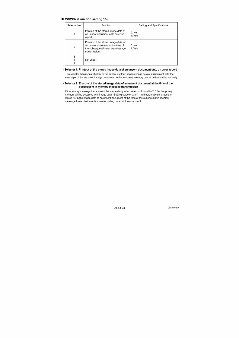
7/18/2019 Brother Mfc 9125cn 9325cw en 5694 Mfp Sm
http://slidepdf.com/reader/full/brother-mfc-9125cn-9325cw-en-5694-mfp-sm 566/597
App.1-33 Confidential
WSW37 (Function setting 15)
- Selector 1: Printout of the stored image data of an unsent document onto an error report
This selector determines whether or not to print out the 1st-page image data of a document onto the
error report if the document image data stored in the temporary memory cannot be transmitted normally.
- Selector 2: Erasure of the stored image data of an unsent document at the time of the
subsequent in-memory message transmission
If in-memory message transmission fails repeatedly when selector 1 is set to “1,” the temporary
memory will be occupied with image data. Setting selector 2 to “1” will automatically erase the
stored 1st-page image data of an unsent document at the time of the subsequent in-memory
message transmission only when recording paper or toner runs out.
Selector No. Function Setting and Specifications
1
Printout of the stored image data of
an unsent document onto an error
report
0: No
1: Yes
2
Erasure of the stored image data of
an unsent document at the time of
the subsequent inmemory message
transmission
0: No
1: Yes
3
l
8
Not used.

7/18/2019 Brother Mfc 9125cn 9325cw en 5694 Mfp Sm
http://slidepdf.com/reader/full/brother-mfc-9125cn-9325cw-en-5694-mfp-sm 567/597
App.1-34 Confidential
WSW38 (V.34 transmission settings)
- Selectors 1 and 2: Setting of the equalizer
These selectors set the equalizer's training level to be applied if the machine fails to send training
due to weak line connection. If these selectors are set to “0, X,” the modem will automatically set
the appropriate training level.
- Selector 3: Sending level of guard tone at phase 2
This selector sets the sending level of guard tone for 1,800 Hz to be sent at Phase 2 in the V. 34 mode.
- Selector 4: Stepping down the transmission speed at fallback each
This selector determines how much the modem steps down the transmission speed at fallback when
called by the remote station. If this selector is set to “1,” the modem may step down the
transmission speed from 33,600 bps to 28,800 bps by one-time fallback.
- Selectors 5 and 6: Automatic control of modem's EQM gain for proper transmission
speed choice
These selectors determine how the modem controls the EQM (Eye Quality Monitor) gain for proper
choice of the transmission speed, which applies if the modem selects higher transmission speed
than the possible speed so that it always repeats falling back.
- Selector 8: Detection of CED for stopping CNG
If this selector is set to “0,” the detection time of CED specified by WSW43, selectors 4 and 5 will apply.
Selector No. Function Setting and Specifications
1
2Setting of the equalizer
No. 1 2
0 0: Automatic
0 1: Automatic1 0: Fixed to 4 points
1 1: Fixed to 16 points
3 Sending level of guard tone at phase 20: Normal - 7 db
1: Normal
4Stepping down the transmission
speed at fallback each
0: 2,400 bps
1: 4,800 bps
5
6
Automatic control of modem's EQM
gain for proper transmission speed
choice
No. 5 6
0 0: For higher transmission speed
than the current setting
0 1: No change from the current
setting
1 0: For lower transmission speed
than the current setting
1 1: For further lower transmission
than the setting made by 1, 0
7Redialing when a communications
error occurs
0: ON
1: OFF
8 Detection of CED for stopping CNG0: ON
1: OFF

7/18/2019 Brother Mfc 9125cn 9325cw en 5694 Mfp Sm
http://slidepdf.com/reader/full/brother-mfc-9125cn-9325cw-en-5694-mfp-sm 568/597

7/18/2019 Brother Mfc 9125cn 9325cw en 5694 Mfp Sm
http://slidepdf.com/reader/full/brother-mfc-9125cn-9325cw-en-5694-mfp-sm 569/597
App.1-36 Confidential
WSW40 (V.34 modem settings)
- Selectors 3 through 8: Masking of symbol rate(s)
These selectors allow you to limit the transmission speed range in V.34 mode by masking the desiredsymbol rate(s). Transmission speeds assigned to the symbol rates are listed on the next page. Thesetting made by these selectors will limit the setting made by selectors 1 through 4 on WSW39.
If selector 3 is set to “1” to mask the 3,429 symbols/second when the first transmission speed choice
is 33,600 bps (specified by selectors 1 through 4 of WSW39), for example, then the allowable
maximum transmission speed will be limited to 31,200 bps. If selector 8 is set to “1” to mask the
2,400 symbols/second when the first transmission speed choice is 33,600 bps, then the allowable
maximum transmission speed remains 33,600 bps.
If selector 8 is set to “1” to mask the 2,400 symbols/second when the first transmission speed choice is
21,600 bps (specified by selectors 1 through 4 on WSW39), then the allowable maximum transmissionspeed remains 21,600 bps but the minimum transmission speed will be limited to 4,800 bps.
Selector No. Function Setting and Specifications
1
2
Not used.
3
l
8
Masking of symbol rate(s)
Not masking Masking
No. 3
No. 4
No. 5
No. 6
No. 7
No. 8
0
0
0
0
-
0
1
1
1
1
-
1
3,429 symbols/sec
3,200 symbols/sec
3,000 symbols/sec
2,800 symbols/sec
Not used.
2,400 symbols/sec
Note:
WSW40 takes effect only when the V.34 mode is permitted (WSW19, selector 7) in models
supporting V.34 mode.
Symbol rateTransmissionspeed (bps)
Symbol rateTransmissionspeed (bps)
Symbol rateTransmissionspeed (bps)
2,400 2,400 3,000 4,800 3,429 4,800
4,800 7,200 7,200
7,200 9,600 9,600
9,600 12,000 12,000
12,000 14,400 14,400
14,400 16,800 16,800
16,800 19,200 19,200
19,200 21,600 21,600
21,600 24,000 24,00026,400 26,400
28,800 28,800
2,800 4,800 3,200 4,800 31,200
7,200 7,200 33,600
9,600 9,600
12,000 12,000
14,400 14,400
16,800 16,800
19,200 19,200
21,600 21,600
24,000 24,000
26,40028,800
31,200

7/18/2019 Brother Mfc 9125cn 9325cw en 5694 Mfp Sm
http://slidepdf.com/reader/full/brother-mfc-9125cn-9325cw-en-5694-mfp-sm 570/597
App.1-37 Confidential
WSW41 (ON-duration of the scanning light source)
- Selectors 5 through 8: Modem attenuator These selectors are used to adjust the transmitting level of the modem when the reception level at
the remote station is improper due to line loss. This function applies to super G3 protocol signals.
WSW42 (Internet mail settings)
Selector No. Function Setting and Specifications
1
l
3
ON-duration of the scanning
light source at room temperature
(Not used.)
4 I-FAX relay report (Not used.)
5
l
8
Modem attenuator
No. 5 6 7 8
0 0 0 0: -10 dBm
0 0 0 1: -11 dBm
0 0 1 0: -12 dBm
0 0 1 1: -13 dBm
0 1 0 0: -14 dBm
|
1 1 1 1: -25 dBm
Selector No. Function Setting and Specifications
1
Access to the incoming mail (POP3)
server (Periodical or on-demand)
(Not used.)
2 Access to the outgoing mail (SMTP)
serve (Not used.)
3 I-FAX relay (Not used.)
4 JBIG encoding system0: Not allowed
1: Allowed
5 Drum discharge detection (Not used.)
6
l
8
Not used.
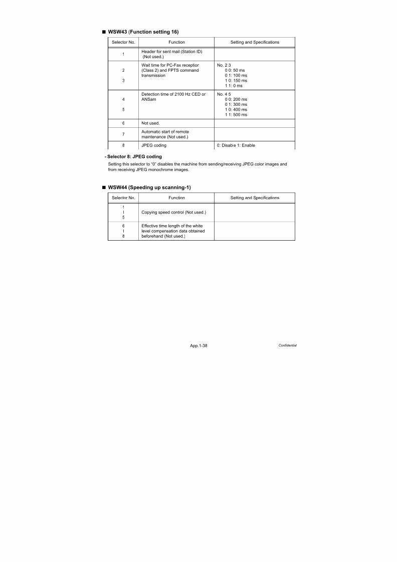
7/18/2019 Brother Mfc 9125cn 9325cw en 5694 Mfp Sm
http://slidepdf.com/reader/full/brother-mfc-9125cn-9325cw-en-5694-mfp-sm 571/597
App.1-38 Confidential
WSW43 (Function setting 16)
- Selector 8: JPEG coding
Setting this selector to “0” disables the machine from sending/receiving JPEG color images and
from receiving JPEG monochrome images.
WSW44 (Speeding up scanning-1)
Selector No. Function Setting and Specifications
1Header for sent mail (Station ID)
(Not used.)
2
3
Wait time for PC-Fax reception
(Class 2) and FPTS command
transmission
No. 2 3
0 0: 50 ms
0 1: 100 ms
1 0: 150 ms
1 1: 0 ms
4
5
Detection time of 2100 Hz CED or
ANSam
No. 4 5
0 0: 200 ms
0 1: 300 ms
1 0: 400 ms
1 1: 500 ms
6 Not used.
7 Automatic start of remote
maintenance (Not used.)
8 JPEG coding 0: Disable 1: Enable
Selector No. Function Setting and Specifications
1
l
5
Copying speed control (Not used.)
6
l
8
Effective time length of the white
level compensation data obtained
beforehand (Not used.)

7/18/2019 Brother Mfc 9125cn 9325cw en 5694 Mfp Sm
http://slidepdf.com/reader/full/brother-mfc-9125cn-9325cw-en-5694-mfp-sm 572/597
App.1-39 Confidential
WSW45 (Speeding up scanning-2)
- Selectors 4 through 6: Periodical correction intervals of the reference voltage appliedto white level compensation for document scanning, during
standby
These selectors set the correction intervals (in seconds) of the reference voltage to be applied to
white level compensation for document scanning during standby, as well as determining whether or
not the controller makes the reference voltage correction during standby. (Conventionally, the
correction has been made immediately before the start of actual scanning)
This function takes effect in copying. Making the correction during standby may shorten the
preparation time for copying.
- Selector 7: Standby position of the CIS unit
This selector determines whether the standby position of the CIS unit should be the home position
or the location of the white-level reference film (attached to the inside of the scanner top cover). If
the location of the reference film is selected, the CIS unit will not return to the home position so as to
shorten the travel time, decreasing the preparation time for copying.
Selector No. Function Setting and Specifications
1
l
3
Delay time from when documents are
set until the ADF starts drawing them
in (Not used.)
4
l
6
Periodical correction intervals of the
reference voltage to be applied to
white level compensation for
document scanning, during standby
No. 4 5 6
0 0 0: No correction of reference
voltage during standby
0 0 1: 10 sec.
0 1 0: 30 sec.
0 1 1: 1 min.
1 0 0: 3 min.
1 0 1: 5 min.
1 1 0: 10 min.
1 1 1: 30 min.
7 Standby position of the CIS unit 0: CIS home position1: Location of the white-level reference film
8Line polarity reverse detection
function
0: No
1: Yes
Note:
Do not access these selectors.

7/18/2019 Brother Mfc 9125cn 9325cw en 5694 Mfp Sm
http://slidepdf.com/reader/full/brother-mfc-9125cn-9325cw-en-5694-mfp-sm 573/597
App.1-40 Confidential
WSW46 (Monitor of power ON/OFF state and parallel port kept at high)
- Selector 4: Previous filtering parameters for white level compensation
At the start of scanning operation, the machine usually initializes white and black level data stored in
the EEPROM by scanning the while-level reference film attached to the inside of the scanner top
cover. After long use of the machine, however, the film may be contaminated with dust or dirt.
Accordingly, incorrect white level data will be set up so that white vertical streaks will be brought on
the scanning result.
Setting this selector to “0” (Enabled) will apply previously saved white level data instead of new
incorrect compensation.
Selector No. Function Setting and Specifications
1
2
Monitoring the PC ON/OFF state
(Not used.)
3Parallel port output pins kept at high
level (Not used.)
4Previous filtering parameters for
white level compensation
0: Enable
1: Disable
5
l
8
Not used.
Note:
Selector 4 is not applicable to models equipped with flat-bed scanners.

7/18/2019 Brother Mfc 9125cn 9325cw en 5694 Mfp Sm
http://slidepdf.com/reader/full/brother-mfc-9125cn-9325cw-en-5694-mfp-sm 574/597
App.1-41 Confidential
WSW47 (Switching between high- and full-speed USB)
WSW48 (USB setup latency)
Selector No. Function Setting and Specifications
1Handling paper at the occurrence of
a paper feed timing error (Not used.)
2Reducing to A4 from B4 and sending
at the real time sending (Not used.)
3
4
Delay of FAX line disconnection
when switching to the pseudoringing
external telephone (Not used.)
5
Disable the ringer of external
telephone at non-ring reception
(Not used.)
6 Not used.
7Disable the ringer of externaltelephone with CAR signal when
caller ID service is available
(Not used.)
8Switching between high-speed USB
and full-speed USB
0: Auto switching between high-speed
USB (ver. 2.0) and full-speed USB
(ver. 1.1)
1: Fixed to full-speed USB (ver. 1.1)
Note:
- Selector 1 is applicable only to models equipped with flat-bed scanners.
- Selectors 3 and 4 are applicable only to models supporting pseudo-ringing of a connectedexternal telephone.
Selector No. Function Setting and Specifications
1
2
Not used.
3
l
5
Number of network TWAIN PCs
registered for each application
No. 3 4 50 0 0: 25 PCs
0 0 1: 50 PCs
0 1 0: 75 PCs
0 1 1: 100 PCs
1 0 0: 125 PCs
1 0 1: 150 PCs
1 1 0: 175 PCs
1 1 1: 200 PCs
6
l
8
USB setup latency (Not used.)

7/18/2019 Brother Mfc 9125cn 9325cw en 5694 Mfp Sm
http://slidepdf.com/reader/full/brother-mfc-9125cn-9325cw-en-5694-mfp-sm 575/597
App.1-42 Confidential
WSW49 (End-of-copying beep and print in black)
- Selectors 4 and 5: Command flag detection time
After receiving a command flag, the machine will wait for the command that should follow for the
time length specified by these selectors.
WSW50 (SDAA settings)
Selector No. Function Setting and Specifications
1
2
RAM disc size in PCL/ PS
(Not used.)
3 End-of-copying beep0: Yes
1: No
4
5
Command flag detection time
No. 4 5
0 0: 150 ms
0 1: 350 ms
1 0: 550 ms
1 1: 750 ms
6
7
CCD unit warm-up time adjustment
(Not used.)
8 Print in black (Not used.)
Selector No. Function Setting and Specifications
1
2
Percentage voltage for interpreting
the external telephone as being
hooked up (based on the network's
standard voltage) (Not used.)
3
DC mask curve table to be applied
when the line is connected
(Not used.)
4 AC impedance to be applied when
the line is connected (Not used.)
5
6
Current control to be applied
immediately after connection of the
line (Not used.)
7
8
AC voltage threshold for detection of
ring (Not used.)

7/18/2019 Brother Mfc 9125cn 9325cw en 5694 Mfp Sm
http://slidepdf.com/reader/full/brother-mfc-9125cn-9325cw-en-5694-mfp-sm 576/597
App.1-43 Confidential
WSW51 (Function setting 17)
WSW52 (Function setting 18)
WSW53 (Function setting 19)
Selector No. Function Setting and Specifications
1
Output of communications error
report when transmission verification
report is disabled
0: Enable
1: Disable
2CR motor torque variation reduction
control (Not used.)
3
4
Cordless handset microphone
volume (Not used.)
5
l
7
Main unit microphone level and echo
cancellation ON/OFF function
(Not used.)
8
Support between nearly empty
→ empty when main unit cover
opened after nearly empty
detected (Not used.)
Selector No. Function Setting and Specifications
1
l
3
Cordless handset microphone level
and echo cancellation ON/OFF
(Not used.)
4
l
6
External telephone pseudo ringing
signal frequency setting (Not used.)
7
Caller ID (number display) display
after the machine has returned to
TEL mode from FAX mode
(Not used.)
8Dial display during transmission
(Not used.)
Selector No. Function Setting and Specifications
1
2
Not used.
3
4
Caller ID (number display) FSK
receiving timing delay setting
(Not used.)
5
6
Caller ID (number display)
instantaneous interrupt detection
time setting (Not used.)
7CNG detection retry after invalid
CNG detected
0: Yes
1: No
8 Decompression of JPEGcompressed file (Not used.)
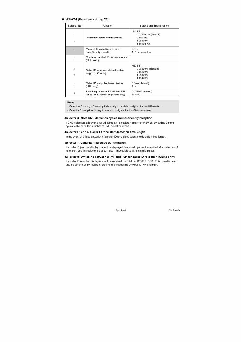
7/18/2019 Brother Mfc 9125cn 9325cw en 5694 Mfp Sm
http://slidepdf.com/reader/full/brother-mfc-9125cn-9325cw-en-5694-mfp-sm 577/597
App.1-44 Confidential
WSW54 (Function setting 20)
- Selector 3: More CNG detection cycles in user-friendly reception
If CNG detection fails even after adjustment of selectors 4 and 5 on WSW26, try adding 2 more
cycles to the permitted number of CNG detection cycles.
- Selectors 5 and 6: Caller ID tone alert detection time length
In the event of a false detection of a caller ID tone alert, adjust the detection time length.
- Selector 7: Caller ID mild pulse transmission
If a caller ID (number display) cannot be displayed due to mild pulses transmitted after detection of
tone alert, use this selector so as to make it impossible to transmit mild pulses.
- Selector 8: Switching between DTMF and FSK for caller ID reception (China only)
If a caller ID (number display) cannot be received, switch from DTMF to FSK. This operation can
also be performed by means of the menu, by switching between DTMF and FSK.
Selector No. Function Setting and Specifications
1
2PictBridge command delay time
No. 1 2
0 0: 100 ms (default)
0 1: 0 ms1 0: 50 ms
1 1: 200 ms
3More CNG detection cycles in
user-friendly reception
0: No
1: 2 more cycles
4Cordless handset ID recovery future
(Not used.)
5
6
Caller ID tone alert detection time
length (U.K. only)
No. 5 6
0 0: 10 ms (default)
0 1: 20 ms
1 0: 30 ms
1 1: 40 ms
7Caller ID wet pulse transmission
(U.K. only)
0: Yes (default)
1: No
8Switching between DTMF and FSK
for caller ID reception (China only)
0: DTMF (default)
1: FSK
Note:
- Selectors 5 through 7 are applicable only to models designed for the UK market.
- Selector 8 is applicable only to models designed for the Chinese market.

7/18/2019 Brother Mfc 9125cn 9325cw en 5694 Mfp Sm
http://slidepdf.com/reader/full/brother-mfc-9125cn-9325cw-en-5694-mfp-sm 578/597
App.1-45 Confidential
WSW55 (Interval of time requred for the developing bias voltage correction )
The setting example of the selector number is as follows;
WSW56 (Function setting 21)
- Selector 6: Switching of the display for the coverage of toner cartridge
This selector specifies the display for the coverage of toner cartridge. Setting this selector to “0”, the
machine displays the coverage only for the current toner cartridge. If this selector sets to “1”, the
machine displays the coverage for all toner cartridge which had been consumed.
- Selector 8: Switching of the CPU sleep modeThis selector specifies the CPU sleep mode ON or OFF.
Selector No. Function Setting and Specifications
1
l
8
Interval of time required for the
developing bias voltage correction
(hour)
0:
1-72:
73-254:
255 (0xFF):
The developing bias voltage
correction is performed on
each print job.
The developing bias voltage
correction is performed
when a print job occurs at
specified time or later.
Not allowed to set.
The developing bias voltage
correction is not performed.
No.1 2 3 4 5 6 7 8
0 0 0 0 0 0 0 0 : The developing bias voltage correction is performed on each print job.
0 0 0 1 1 0 0 0 : The developing bias voltage correction is performed when a print job occursafter 24 hours or later.
0 0 0 1 0 0 1 0 : The developing bias voltage correction is performed when a print job occurs
after 72 hours or later.
1 1 1 1 1 1 1 1 : The developing bias voltage correction is not performed.
Selector No. Function Setting and Specifications
1PS emulation function setting
(Not used.)
2Switching of the PPT setting
(Not used.)
3“Last Job Reprint” function setting
(Not used.)
4 Wireless LAN function (Not used.)
5Switching of the echo suppressionimprovement during calling (Not used.)
6Switching of the display for the
coverage of toner cartridge
0: The coverage only for the current
toner cartridge
1: The coverage for all toner cartridges
which had been consumed
7PCL emulation function setting
(Not used.)
8 Switching of the CPU sleep mode0: Invalid
1: Valid (default)

7/18/2019 Brother Mfc 9125cn 9325cw en 5694 Mfp Sm
http://slidepdf.com/reader/full/brother-mfc-9125cn-9325cw-en-5694-mfp-sm 579/597
App.1-46 Confidential
WSW57 (Function setting 22)
WSW58 (Function setting 23)
Selector No. Function Setting and Specifications
1
l
3
Caller ID judgment voltage (to be
distinguished from rings) (Not used.)
4
l
6
Caller ID judgment voltage (to be
distinguished from reverse polarity
voltages) (Not used.)
7 Caller ID burst link time limit0: Enable
1: Disable
8Base unit Start button after cordless
handset dialing (Not used.)
Selector No. Function Setting and Specifications
1
l
3
Prevention of line interrupt during
ICM recording (ratio of guard tone
response time to call end tone ON
time) (Not used.)
4
5
Not used.
6
Extension of the “No. of CNG cyclesto be detected” (which allows two
cycles to be added to the cycles
specified by selectors 6 and 7 on
WSW26 and selectors 4 and 5 on
WSW34) (Not used.)
7
8
No. of busy tone detection cycles
(Not used.)

7/18/2019 Brother Mfc 9125cn 9325cw en 5694 Mfp Sm
http://slidepdf.com/reader/full/brother-mfc-9125cn-9325cw-en-5694-mfp-sm 580/597
App.1-47 Confidential
WSW59 (Function setting 24)
- Selector 1: USB serial number (SN) transmission enabled/disabled
This is intended to prevent the problem of a continued increase in USB ports when serial numbers are
transmitted from the MFC to a Windows Vista-based PC.
It is intended only to prevent a problem specific to Windows Vista; its default setting is “0: USB SN enabled.”
- Selector 2: Extension of the waiting time between ANSam and DIS
Setting this selector to “0” extends the waiting time between the ANSam and DIS in order to secure
the time required for switching the calling machine's echo suppressor in transmission from a G3 to
G4 FAX machine.
- Selectors 3 through 7: Checking of the specified character code set when displayingor printing the folder/file names stored in memory cards or
USB flash memory drives
The language is switched to a relevant one when a file name cannot be identified.
- Selector 8: Improvement of DTMF detection function (to minimize the effects ofmomentary power failure or noise)
Be effective only MFC-9120CN/9125CN/9320CW/9325CW.
Selector No. Function Setting and Specifications
1USB serial number (SN)
transmission enabled/disabled
0: USB serial number transmitted/USB
serial number not transmitted
1: Frame length selection
2Extension of the waiting time
between ANSam and DIS
0: Enable (default)
1: Disable
3
l7
Checking of the specified character
code set when displaying or printing
the folder/file names stored inmemory cards or USB flash memory
drives
No. 34567
00000: ASC11 (default for USA/
European models)
00001: Latin1 (CP1252)
00010: Latin2 (CP1250)
00011: Cyrillic (CP1251)
00100: SJIS (CP932) (default for
Japanese models)
00101: Thai (CP874)00110: Korean (CP949)
00111: Traditional Chinese (CP950)
01000: Simplified Chinese (CP936)
(default for Chinese and
Asia & Pacific models)
01001: Arabic (CP1256)
01010:
| Reserved.
11111:
8
Improvement of DTMF detection
function (to minimize the effects of
momentary power failure or noise)
0: Disable (default)
1: Enable

7/18/2019 Brother Mfc 9125cn 9325cw en 5694 Mfp Sm
http://slidepdf.com/reader/full/brother-mfc-9125cn-9325cw-en-5694-mfp-sm 581/597
App.1-48 Confidential
WSW60 (Function setting 25)
- Selector 6: Output of CNG detection result to the activity report
Setting this selector to “1” (Enable) changes the items to be listed in the activity report as follows.
Selector No. Function Setting and Specifications
1
l
3
Not used.
4
5
Caller ID primary closed circuit timing
adjustment
No. 4 5
0 0: OFF
0 1: Fast
1 0: Normal
1 1: Slow
6Output of CNG detection result to the
activity report
0: Disable (default)
1: Enable
7
l
8
Delay time which allows a polarity
inversion interrupt from polarity
inversion judgment
No. 7 8
0 0: 500 ms
0 1: 750 ms
1 0: 1,000 ms
1 1: 1,500 ms
FAX No./NAME CNG DETECTION STATE
(Tone detection status, calling/called status)
DURATION RCV MODE
(FAX receive mode setting)
PAGE (S) EASY RCV
(Easy receive setting)
RESULT TRIGGER
(FAX receive trigger)

7/18/2019 Brother Mfc 9125cn 9325cw en 5694 Mfp Sm
http://slidepdf.com/reader/full/brother-mfc-9125cn-9325cw-en-5694-mfp-sm 582/597
App.1-49 Confidential
WSW61 (Scanning light intensity to judge to be stable 1)
WSW62 (Scanning light intensity to judge to be stable 2)
- Selectors 5 through 8: Selection of judging function for scanning pages compensation
These selectors set the condition to control scanning pages compensation. Some operation losses
occur in the control of the compensation. If you want to start scanning immediately even if the
image quality is not good, set to “01: Not discriminates”. If you want to give priority to the image
quality even though losses are increased, select one of others (“00: Discriminates depending on the
rate of change” or “10: Discriminates every page”).
Selector No. Function Setting and Specifications
1
l
4
Change rate of the CCD scanning
light intensity to judge to be stable in
the long time mode (Not used.)
5
l
8
Change rate of the CCD scanning
light intensity to judge to be stable in
the short time mode (Not used.)
Selector No. Function Setting and Specifications
1
l4
Change rate of the CCD light
intensity for scanning pagescompensation (Not used.)
5
6
Selection of judging function for
simple scanning pages
compensation
No. 5 6
0 0: Judges according to the
change rate
0 1: Not judges
1 0: Judges every page
7
8
Selection of judging function for
regular scanning pages
compensation
No. 7 8
0 0: Judges according to the
change rate
0 1: Not judges
1 0: Judges every page
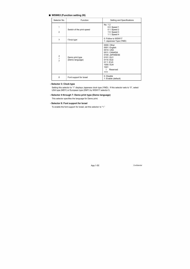
7/18/2019 Brother Mfc 9125cn 9325cw en 5694 Mfp Sm
http://slidepdf.com/reader/full/brother-mfc-9125cn-9325cw-en-5694-mfp-sm 583/597
App.1-50 Confidential
WSW63 (Function setting 26)
- Selector 3: Clock type
Setting this selector to “1” displays Japanese clock type (YMD). If this selector sets to “0”, select
USA type (MDY) or European type (DMY) by WSW17 selector 5.
- Selector 4 through 7: Demo print type (Demo language)
This selector specifies the language for Demo print.
- Selector 8: Font support for Israel
To enable the font support for Israel, set this selector to “1.”
Selector No. Function Setting and Specifications
1
2Switch of the print speed
No. 1 2
0 0: Speed 1
0 1: Speed 21 0: Speed 3
1 1: Speed 4
3 Clock type0: Follow to WSW17
1: Japanese Type (YMD)
4
l
7
Demo print type
(Demo language)
0000: Other
0001: English
0010: USA
0011: CANADA
0100: JAPANESE
0101: EU1
0110: EU20111: EU3
1000: EU4
1001
l Reserved
1111
8 Font support for Israel0: Disable
1: Enable (default)

7/18/2019 Brother Mfc 9125cn 9325cw en 5694 Mfp Sm
http://slidepdf.com/reader/full/brother-mfc-9125cn-9325cw-en-5694-mfp-sm 584/597
App.1-51 Confidential
WSW64 (Setting the language/Default paper size)
- Selectors 1 through 6: Setting the language
Set the language displayed in the LCD.
WSW65 (Setting the paper support)
Selector No. Function Setting and Specifications
1
l
6
Setting the language
No.1 2 3 4 5 6
0 0 0 0 0 0: English
0 0 0 0 0 1: French
0 0 0 0 1 0: German0 0 0 0 1 1: Dutch
0 0 0 1 0 0: Spanish
0 0 0 1 0 1: Italian
0 0 0 1 1 0: Norwegian
0 0 0 1 1 1: Portuguese
0 0 1 0 0 0: Danish
0 0 1 0 0 1: Swedish
0 0 1 0 1 0: Finnish
0 0 1 0 1 1: Czech
0 0 1 1 0 0: Polish
0 0 1 1 0 1: Hungarian
0 0 1 1 1 0: Russian0 0 1 1 1 1: Bulgarian
0 1 0 0 0 0: Romanian
0 1 0 0 0 1: Slovakian
0 1 0 0 1 0: Brazilian
0 1 0 0 1 1: Turkish
0 1 0 1 0 0: Japanese
0 1 0 1 0 1: Reserve
7
l
8
Default paper size
No. 7 8
0 0: Letter
0 1: A4
1 0: Reserve
1 1: Reserve
Selector No. Function Setting and Specifications
1
2Default media type
No. 1 2
0 0: Plain Paper
0 1: Thin Paper 1 0: Reserve
1 1: Reserve
3 Supporting of BOND paper 0: Disable
1: Enable
4 Supporting of HAGAKI paper 0: Disable
1: Enable
5 Supporting of OHP (Not used.)
6 Supporting of LABEL paper 0: Disable
1: Enable
7
8Not used.

7/18/2019 Brother Mfc 9125cn 9325cw en 5694 Mfp Sm
http://slidepdf.com/reader/full/brother-mfc-9125cn-9325cw-en-5694-mfp-sm 585/597
App.1-52 Confidential
WSW66 (Reserved *Change of the setting is prohibited)
WSW67 (Reserved *Change of the setting is prohibited)
WSW68 (Reserved *Change of the setting is prohibited)
WSW69 (Reserved *Change of the setting is prohibited)
WSW70 (Reserved *Change of the setting is prohibited)
WSW71 (Reserved *Change of the setting is prohibited)
Selector No. Function Setting and Specifications
1
l
8
Reserved
* Change of the setting is prohibited.
Selector No. Function Setting and Specifications
1
l
8
Reserved
* Change of the setting is prohibited.
Selector No. Function Setting and Specifications
1
l
8
Reserved
* Change of the setting is prohibited.
Selector No. Function Setting and Specifications
1
l
8
Reserved
* Change of the setting is prohibited.
Selector No. Function Setting and Specifications
1
l8
Reserved* Change of the setting is prohibited.
Selector No. Function Setting and Specifications
1
l
8
Reserved
* Change of the setting is prohibited.

7/18/2019 Brother Mfc 9125cn 9325cw en 5694 Mfp Sm
http://slidepdf.com/reader/full/brother-mfc-9125cn-9325cw-en-5694-mfp-sm 586/597
App.1-53 Confidential
WSW72 (Reserved *Change of the setting is prohibited)
WSW73 (Reserved *Change of the setting is prohibited)
WSW74 (ADF stop control)
WSW75 (Paper feeding parameter for turning the document counter when themachine takes action duplex scanning)
Selector No. Function Setting and Specifications
1
l
8
Reserved
* Change of the setting is prohibited.
Selector No. Function Setting and Specifications
1
l
8
Reserved
* Change of the setting is prohibited.
Selector No. Function Setting and Specifications
1
l
8
ADF stop control (Not used.)
Selector No. Function Setting and Specifications
1
The setting to increase or decrease
the feed distance when a document
is inverted in the 2-sided scanning
(Not used.)
2
l
8
Feed distance parameter when a
document is inverted in the 2-sided
scanning (Not used.)

7/18/2019 Brother Mfc 9125cn 9325cw en 5694 Mfp Sm
http://slidepdf.com/reader/full/brother-mfc-9125cn-9325cw-en-5694-mfp-sm 587/597
App.1-54 Confidential
WSW76 (The limited number of the documents in reverse for paper ejection ofthe simplex scanning from ADF)
- Selectors 1 through 8: The limited number of the documents in reverse for paperejection of the simplex scanning from ADF
These selectors are used to set the limited number of the paper ejection under the following
condition.- The machine takes action simplex scanning from the ADF.
- The documents which are stacked on the ADF are ejected in reverse of the documents which has
been scanned.
There is a possibility that loading problem or dog-ear problem occurs if the limited number is over a
maximum number which machine can paper feeding.
WSW77 (The limited number of the documents in reverse for paper ejection ofthe duplex scanning from ADF)
- Selectors 1 through 8: The limited number of the documents in reverse for paperejection of the duplex scanning from ADF
These selectors are used to set the limited number of the paper ejection when the machine takes
action duplex scanning from the ADF.
There is a possibility that loading problem or dog-ear problem occurs if the limited number is over a
maximum number which machine can paper feeding.
Selector No. Function Setting and Specifications
1
l
8
The limited number of the documents
in reverse for paper ejection of the
simplex scanning from ADF
No. 1 2 3 4 5 6 7 8
0 0 0 0 0 0 0 0: 0
0 0 0 0 0 0 0 1: 1
0 0 0 0 0 0 1 0: 2
0 0 0 0 0 0 1 1: 3
0 0 0 0 0 1 0 0: 4
l
0 1 1 0 0 0 1 1: 99
0 1 1 0 0 1 0 0 or later: Invalidity
Selector No. Function Setting and Specifications
1
l
8
The limited number of the documents
in reverse for paper ejection of the
duplex scanning from ADF
No. 1 2 3 4 5 6 7 8
0 0 0 0 0 0 0 0: 0
0 0 0 0 0 0 0 1: 1
0 0 0 0 0 0 1 0: 2
0 0 0 0 0 0 1 1: 3
0 0 0 0 0 1 0 0: 4
l
0 1 1 0 0 0 1 1: 99
0 1 1 0 0 1 0 0 or later: Invalidity

7/18/2019 Brother Mfc 9125cn 9325cw en 5694 Mfp Sm
http://slidepdf.com/reader/full/brother-mfc-9125cn-9325cw-en-5694-mfp-sm 588/597
Confidential
APPENDIX 2.DELETION OF USER SETTING INFORMATION etc.
This appendix provides instructions on how to delete user setting information etc. recorded in the machine.

7/18/2019 Brother Mfc 9125cn 9325cw en 5694 Mfp Sm
http://slidepdf.com/reader/full/brother-mfc-9125cn-9325cw-en-5694-mfp-sm 589/597
App.2-1 Confidential
DELETION OF USER SETTING INFORMATION, ETC.
User setting such as wired and wireless network settings in the machine is recorded in the EEPROM
and the Flash memory on the Main PCB. Follow the procedure described below to delete this
information with a single operation.
- Your name and telephone number
- Telephone directory data
- Group dialing data
- Dispatch history data
- FAX forwarding destination data
- Password
- Memory data
- No transfer of PC-FAX received data
- Ready polling data
- Timer sending data
- Collective sending data
- Received calls data
- Communication management report
- Net-related information
<Operating Procedure>
(1) Press the MENU button.
(2) Press the or button, then the “General Setup” will appear on the LCD and press the OK
button.
(3) Press the or button, then the “Reset” will appear on the LCD and press the OK button.
(4) Press the or button, then the “All Setting” will appear on the LCD and press the OK
button.
“1. Reset 2. Exit” will appear on the LCD.
(5) Press the 1 button to delete the User Setting Information, etc and returns to the ready mode.

7/18/2019 Brother Mfc 9125cn 9325cw en 5694 Mfp Sm
http://slidepdf.com/reader/full/brother-mfc-9125cn-9325cw-en-5694-mfp-sm 590/597
Confidential
APPENDIX 3.SERIAL NUMBERING SYSTEM

7/18/2019 Brother Mfc 9125cn 9325cw en 5694 Mfp Sm
http://slidepdf.com/reader/full/brother-mfc-9125cn-9325cw-en-5694-mfp-sm 591/597
App.3-1 Confidential
SERIAL NUMBERING SYSTEMEach machine has a serial number label for the machine itself and property labels for some other
parts. Refer to the information below for the meaning of the serial number and property codes and
the location of each label.
Serial number labels for the machine itself
<Location>
Fig. App 3-1
Fig. App 3-2 Fig. App 3-3
Serial number
Serial number (6-digit)
Manufacturing factory No.
9: 2009
0: 2010
A: January
B: February
C: MarchD: April
E: May
F: June
G: JulyH: August
J: September
K: October
L: November M: December
Year of manufacture
Month of manufacture
A 9 J 1 1 1 1 0 1
Model number
Serial label Serial label
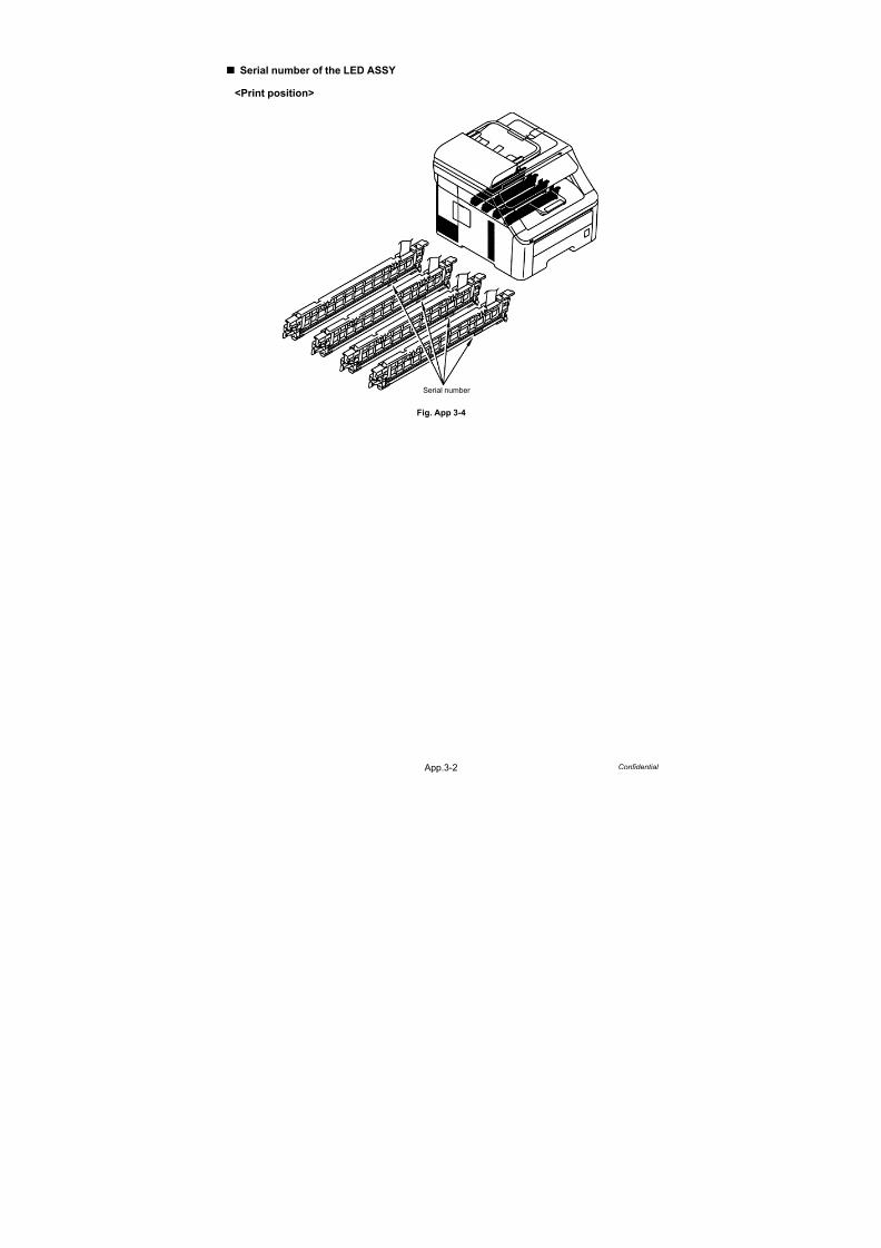
7/18/2019 Brother Mfc 9125cn 9325cw en 5694 Mfp Sm
http://slidepdf.com/reader/full/brother-mfc-9125cn-9325cw-en-5694-mfp-sm 592/597
App.3-2 Confidential
Serial number of the LED ASSY
<Print position>
Fig. App 3-4
Serial number

7/18/2019 Brother Mfc 9125cn 9325cw en 5694 Mfp Sm
http://slidepdf.com/reader/full/brother-mfc-9125cn-9325cw-en-5694-mfp-sm 593/597
Confidential
APPENDIX 4.SCREW CATALOGUE

7/18/2019 Brother Mfc 9125cn 9325cw en 5694 Mfp Sm
http://slidepdf.com/reader/full/brother-mfc-9125cn-9325cw-en-5694-mfp-sm 594/597
App.4-1 Confidential
SCREW CATALOGUE
Screw pan (S/P washer)
Taptite pan
Shoulder screw
Taptite bind B
Taptite bind S
Taptite cup B
Taptite bind B
M3x8
Taptite bind B
M3x10
Taptite bind B
M3x12
Taptite bind B
M4x12
Taptite bind S
M3x5
Taptite cup B
M3x8
Taptite cup B
M3x10
Taptite pan B M4x14
Shoulder screw
Shoulder screw
M3
Screw pan (S/P washer)
M4x8 DB
Taptite pan (S/P W)
Taptite pan (washer)
Taptite cup S
Taptite cup S
M3x12
Taptite cup S
M3x6 SR
Taptite bind S
M3x6
Screw bind
Screw bind
M3x4
Taptite pan (S/P W)
B M3x10
Taptite pan (washer)
B M4x12 DA
Screw pan (S/P washer)
M4x8
Screw pan (S/P washer)
M3.5x6

7/18/2019 Brother Mfc 9125cn 9325cw en 5694 Mfp Sm
http://slidepdf.com/reader/full/brother-mfc-9125cn-9325cw-en-5694-mfp-sm 595/597
Confidential
APPENDIX 5.REFERENCES

7/18/2019 Brother Mfc 9125cn 9325cw en 5694 Mfp Sm
http://slidepdf.com/reader/full/brother-mfc-9125cn-9325cw-en-5694-mfp-sm 596/597
App.5-1 Confidential
REFERENCES
This page provides reference information.
It is possible to get the full instructions of the subjects by just clicking on the links below.
1. Machine specification
(Refer to “2. SPECIFICATIONS LIST” in Chapter 1.)
2. Paper specification
(Refer to “2.5 Paper” in Chapter 1.)
3. Error codes(Refer to “2.1 Error Codes” in Chapter 3.)
4. Error message
(Refer to “2.3 Error Cause and Remedy” in Chapter 3.)
5. Pitch indicated in roller image
(Refer to “4.2 Pitch Indicated in Roller Image” in Chapter 3.)
6. Periodical maintenance parts
(Refer to “3.1 Periodical Maintenance Parts” in Chapter 4.)
7. Reset parts life
(Refer to “2.1 Resetting the Periodical Maintenance Parts Life” in Chapter 7.)

7/18/2019 Brother Mfc 9125cn 9325cw en 5694 Mfp Sm
http://slidepdf.com/reader/full/brother-mfc-9125cn-9325cw-en-5694-mfp-sm 597/597