Embed Size (px)
Citation preview
© Keith Brunt
Broken Earth Neutral faults in distribution systems with
Traffic Signal loads.
Recent issues with PME supply systems could have a maintenance legacy for
street equipment such as traffic signals.
As an electrical design engineer I have to work closely with my electricity
provider. What they offer in the way of an earthing arrangement will greatly
affect my design, and whether or not I will need to use a Residual Current
Device (RCD) for earth fault protection. For traffic signals I would rather not
use an RCD but what I put on the street must be safe.
If I provided a RCD for every traffic signal site I designed this would amount to
a huge maintenance legacy. Could this be avoided? Well, yes, providing the
electricity provider, also known as the Distribution Network Operator (DNO)
can provide a good earth system such as a Protective Multiple Earth (PME)
system sometimes referred to as TN-C-S. However, lately there has been a
shift away from offering PME systems to street equipment particularly with a
connected load of 2kW or more. This is due to a specific fault that might occur
with a damaged DNO supply cable. For traffic signal installations could
intelligent traffic signal controllers be the answer?
Introduction
We take electricity for granted. Most of us know there are three pins to be found on a
typical BS1363 plug used for an electrical appliance and most people are aware of
the terms live, neutral and earth, the earth connection being important for safety. The
earth connection ensures the metalwork of an electrical system cannot become live
giving rise to danger and thus an electric shock.
Just how does the electrical supply industry provide us, the consumer, with an earth
connection? To answer this we need to look back at the history of electricity and then
understand how it evolved into the system we now use.
The Background
The idea of a standardised electrical system was first put forward by Charles Merz in
1916, and this eventually lead to the 1926 Electricity Act and the setting up of a
national grid for distribution throughout the UK. However, at consumer level the
voltages and systems still varied, with both alternating current and direct current
systems in common use and the voltage typically around 250v. It would take several
more years before we eventually arrived at the standardised system of 230/400volt
alternating current using 2/3/4wires for connection. For traffic signals we need only
consider the use of a 230volt a.c. 2 wire system see fig 1. That is to say 230volt
© Keith Brunt
alternating current being supplied using 2 wires, the Live or line as it is now known
and a neutral, plus a suitable earthing system.
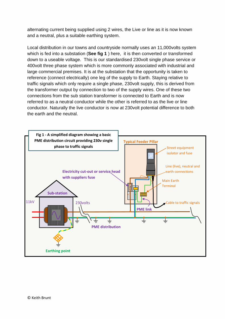
Local distribution in our towns and countryside normally uses an 11,000volts system
which is fed into a substation (See fig 1 ) here, it is then converted or transformed
down to a useable voltage. This is our standardised 230volt single phase service or
400volt three phase system which is more commonly associated with industrial and
large commercial premises. It is at the substation that the opportunity is taken to
reference (connect electrically) one leg of the supply to Earth. Staying relative to
traffic signals which only require a single phase, 230volt supply, this is derived from
the transformer output by connection to two of the supply wires. One of these two
connections from the sub station transformer is connected to Earth and is now
referred to as a neutral conductor while the other is referred to as the live or line
conductor. Naturally the live conductor is now at 230volt potential difference to both
the earth and the neutral.
60
A
TRAFFI
C
SIGNAL
S
230volts 11kV
Earthing point
Sub-station
Street equipment
isolator and fuse
Line (live), neutral and
earth connections Electricity cut-out or service head
with suppliers fuse Main Earth
Terminal
Cable to traffic signals
PME link
Typical Feeder Pillar
PME distribution
Fig 1 - A simplified diagram showing a basic
PME distribution circuit providing 230v single
phase to traffic signals
© Keith Brunt
This simply means that connecting one of the transformers output wires to Earth not
only gives us a protective system which we commonly call earth but also provides
the other connection as a line or live connection. This makes things simple as any
fuse or protective device is only required to be placed in the Line or Live wire of the
circuit. Another advantage is as long as any protective devices such as circuit
breakers, fuses and switches are placed in the line (live) conductor then the circuit
will be deemed safe whenever the line (live) conductor is switched (disconnected).
Also, in the event of a fault, that is a short circuit to earth and/or neutral, the
protective device will automatically operate rendering the circuit safe simply by
having disconnected the line (live) conductor. This is one of the basic methods of
protection given in the IET regs BS7671:2008 – everything earthed and correct use
of automatic protective devices.
So, one element of a good design is fulfilled by ensuring all metalwork associated
with the installation is properly connected together and bonded to earth. The earthing
system needs to be capable of passing the short circuit current safely without
causing damage or causing harm to persons or livestock. This not only means being
able to withstand the high currents that may flow during these faults but also
ensuring any voltage that may exist in earthed metalwork etc remains low enough
not to be harmful. A good system means all metal work being securely connected
together and a good connection to Earth, such as offered by the PME system.
However, it would seem changes are ahead of us. The PME earth system is now
seen as risky in which case the DNO will force the customer to use Terra Terra (TT)
system and thus use an RCD. The use of RCD’s could result in less reliable
electrical systems. This might not matter for illuminated advertising or bus stops etc
but for traffic signals this might be considered risky. As with most engineering there
is a balance to be had and in this case it is the very unlikely occurrence of a person
receiving a shock verses possible accidents due to the traffic signals being out.
Consideration must be given to which of these two incidents is most likely to occur.
The designer needs to take all this in to consideration. Where traffic signals are in
abundance RCD’s could, not only be very expensive maintenance wise, but also be
a significant hazard for, when traffic signals are out problems soon start to occur for
traffic trying to use busy intersections and/or not to mention the pedestrians trying to
cross the road. People soon become impatient and so the less time traffic signals
are out the better for all users. RCD’s are brilliant devices but can trip all too easily
leaving a critical junction to fend for itsself. Additionally, the RCD will need to be
tested regularly, say once a year. While the test doesn’t take too long, the load,
namely the traffic signals, will have to be isolated while the testing takes place
resulting in more down time.
© Keith Brunt
The PME Issue
The distribution of electricity in towns and cities is complex; however, the service
generally comes with a reliable earth connection unlike those in more rural districts
where the customers are often required to provide their own connection to the
ground in order to get an earth connection. This earth system is referred to as TT.
Meaning there is an earth electrode connection at the substation and another at the
customer’s premises but no direct connection via a cable. Consequently, the TT
system tends not to perform as well as a system where the earth connection is
derived via the DNO’s cables. In this case the designer will use a RCD for protection
against faults to earth whereas a fuse or Miniature Circuit Breaker (MCB) may have
been acceptable in the PME (TN-C-S) system.
RCD’s are very good at detecting leakage currents to earth but are, unfortunately,
unforgiving with stray currents caused by say, electronic equipment incorporating
filters, or even those caused by maintenance personnel connecting test equipment.
Naturally this depends on the type of RCD device selected, for example, a 30mA
device will trip more easily than say a 300mA and again careful good design must
prevail.
As mentioned, earthing in towns and cities is normally provided by using the PME
system. The distribution cable being of a special design and consists of three line
conductors, (one for each of the three phases) surrounded by the protective earth
neutral on the outside. This is referred to as a Protective Earth Neutral (PEN)
conductor. It has been common practice for a number of years to use this combined
Sub-station
230volts
Fig 2 - A simplified diagram showing a basic
PME circuit in normal operation
PEN conductor Lo
ad
PME Service
Suppliers
Cut-out
N
E
earthed
metal work Load Current
E
PME Link
L
Multiple earths
Resistance
of the load Earthing point
0volts
All Safe
© Keith Brunt
neutral and earth system along with its multiple earthing points as a means of
supplying electricity to customers. It was deemed to be not only cost effective, but
better and safer than having a cable with separate earth and neutral conductors.
This gave rise to the popularity of the PME system. This is also referred to as TN-C-
S, meaning Terra (earth) and neutral connected at the sub-station (TN) and then
combined (C) together in the supply cable (this is the PEN conductor) to the
customer where the earth and neutral are then separated (S). Multiple earth because
the PEN conductor is connected to Earth at regular points along the length of the
cable Fig 2. Thus the PME system became widely adopted by the UK. However,
now, the PME system is being viewed as risky and particularly where the customer is
using electricity on the street, for surrounding the installation is a large conductive
area, open to the elements and often wet with rainfall, a very risky environment.
The PME risk increases with large loads exceeding 2000 watts (2kW). These loads
are not seen as safe for connection to a PME system in the street environment. The
reason being is that it is a risk within the supply network itself. There is now a danger
that all earthed metalwork associated with a PME services could become “live” if
there is a damaged or disconnected PEN conductor in the supply cable.
Normal operation
In normal operation, the current drawn by the load returns back to the source
transformer via the installation neutral conductors and then via the PEN conductor in
the distribution network’s PME cable. See load current in Fig 2.
An earth fault current will return to the source transformer in a similar way using the
customer’s earth conductors, then by way of passing through the PME link to the
PEN, conductor. This has the advantage of providing low earth loop impedance, that
is to say the resistance in the circuit is low which ensures a high fault current which,
in turn is important for operating the fuse or MCB and removing the danger quickly
(automatic disconnection).
The Culprit
So, it can be seen that the distribution network’s PEN conductor along with its
multiple earth points is paramount to safe operation of equipment and circuits within
the customers’ installation. However, it cannot be ignored that if the PEN conductor
did become broken somewhere between the customers installation and the last
reliable earthing point any earthed metal work could be live. This may sound strange
at first but studying the diagram Fig 3 it can be seen the culprit is the link between
neutral and earth, the PME link. Consider that in basic circuit theory if no current
flows then no voltage can be dropped or lost across the load and therefore the
supply voltage will be found to exist on the neutral side of the load as well as on the
live/line side. Now consider, the neutral conductor is also connected to earth via the
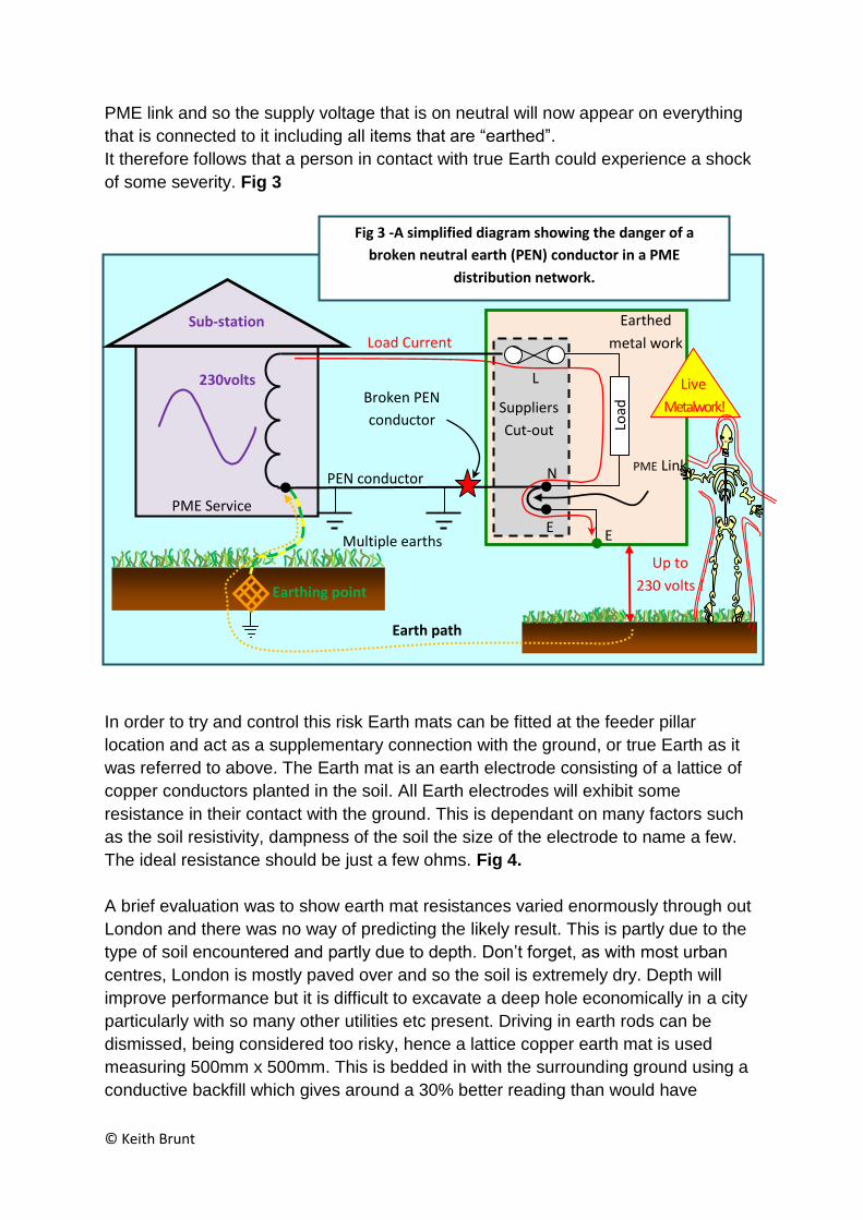
© Keith Brunt
PME link and so the supply voltage that is on neutral will now appear on everything
that is connected to it including all items that are “earthed”.
It therefore follows that a person in contact with true Earth could experience a shock
of some severity. Fig 3
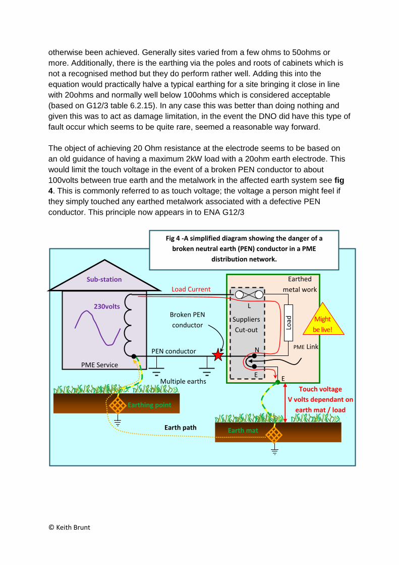
In order to try and control this risk Earth mats can be fitted at the feeder pillar
location and act as a supplementary connection with the ground, or true Earth as it
was referred to above. The Earth mat is an earth electrode consisting of a lattice of
copper conductors planted in the soil. All Earth electrodes will exhibit some
resistance in their contact with the ground. This is dependant on many factors such
as the soil resistivity, dampness of the soil the size of the electrode to name a few.
The ideal resistance should be just a few ohms. Fig 4.
A brief evaluation was to show earth mat resistances varied enormously through out
London and there was no way of predicting the likely result. This is partly due to the
type of soil encountered and partly due to depth. Don’t forget, as with most urban
centres, London is mostly paved over and so the soil is extremely dry. Depth will
improve performance but it is difficult to excavate a deep hole economically in a city
particularly with so many other utilities etc present. Driving in earth rods can be
dismissed, being considered too risky, hence a lattice copper earth mat is used
measuring 500mm x 500mm. This is bedded in with the surrounding ground using a
conductive backfill which gives around a 30% better reading than would have
Sub-station
Earthing point
Earth path
230volts
Fig 3 -A simplified diagram showing the danger of a
broken neutral earth (PEN) conductor in a PME
distribution network.
Broken PEN
conductor
PEN conductor
Load
PME Service
Suppliers
Cut-out
N
E
Earthed
metal work Load Current
Multiple earths
Resistance
of the load
Live
Metalwork!
Up to
230 volts !
E
PME Link
L
© Keith Brunt
otherwise been achieved. Generally sites varied from a few ohms to 50ohms or
more. Additionally, there is the earthing via the poles and roots of cabinets which is
not a recognised method but they do perform rather well. Adding this into the
equation would practically halve a typical earthing for a site bringing it close in line
with 20ohms and normally well below 100ohms which is considered acceptable
(based on G12/3 table 6.2.15). In any case this was better than doing nothing and
given this was to act as damage limitation, in the event the DNO did have this type of
fault occur which seems to be quite rare, seemed a reasonable way forward.
The object of achieving 20 Ohm resistance at the electrode seems to be based on
an old guidance of having a maximum 2kW load with a 20ohm earth electrode. This
would limit the touch voltage in the event of a broken PEN conductor to about
100volts between true earth and the metalwork in the affected earth system see fig
4. This is commonly referred to as touch voltage; the voltage a person might feel if
they simply touched any earthed metalwork associated with a defective PEN
conductor. This principle now appears in to ENA G12/3
Sub-station
Earthing point
Earth path
230volts
Fig 4 -A simplified diagram showing the danger of a
broken neutral earth (PEN) conductor in a PME
distribution network.
Broken PEN
conductor
PEN conductor
Load
PME Service
Suppliers
Cut-out
N
E
Earthed
metal work Load Current
Multiple earths
Resistance
of the load
Might
be live!
Touch voltage
V volts dependant on
earth mat / load
E
PME Link
L
Earth mat
© Keith Brunt
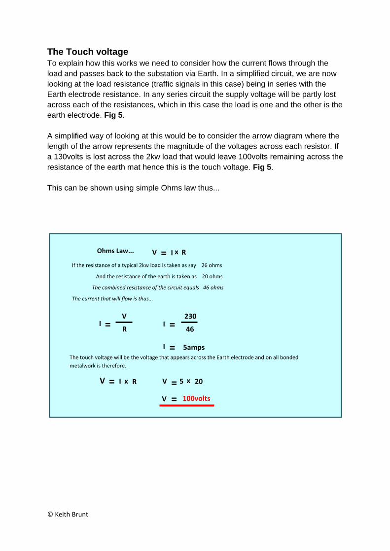
The Touch voltage
To explain how this works we need to consider how the current flows through the
load and passes back to the substation via Earth. In a simplified circuit, we are now
looking at the load resistance (traffic signals in this case) being in series with the
Earth electrode resistance. In any series circuit the supply voltage will be partly lost
across each of the resistances, which in this case the load is one and the other is the
earth electrode. Fig 5.
A simplified way of looking at this would be to consider the arrow diagram where the
length of the arrow represents the magnitude of the voltages across each resistor. If
a 130volts is lost across the 2kw load that would leave 100volts remaining across the
resistance of the earth mat hence this is the touch voltage. Fig 5.
This can be shown using simple Ohms law thus...
If the resistance of a typical 2kw load is taken as say 26 ohms
And the resistance of the earth is taken as 20 ohms
The combined resistance of the circuit equals 46 ohms
The current that will flow is thus...
The touch voltage will be the voltage that appears across the Earth electrode and on all bonded
metalwork is therefore..
I 5amps
= I 46
230
=
= I R
V
V = I R x Ohms Law...
V = 5 20 x
V = 100volts
V = I R x

© Keith Brunt
This explains the reasoning behind having a 2kW load operating with a 20 ohm
(max) Earth electrode. However, what happens if either the load or the Earth
electrode resistances are varied?
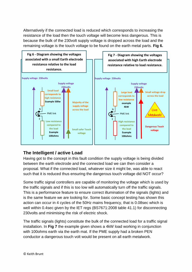
Starting with the Earth electrode; consider the load remaining at 26 ohms (roughly
the resistance of a 2kW load) and as the resistance of the Earth electrode
approaches 0 ohms so the voltage dropped across it approaches 0 volts. This
means the touch voltage is becoming less dangerous Fig 6.
Conversely, if the Earth mat resistance increases above 100ohms then the touch
voltage increases towards the supply voltage 230volts. Fig 7.
Now, let’s consider variations in the load resistance. Consider the Earth electrode
remaining at 100 ohms and the resistance of the load decreasing due to having a
larger connected load, an increase in kW. As this resistance approaches 0 ohms so
the voltage dropped across the connected load decreases and this means the
remaining voltage, the touch voltage, is becoming dangerously high. Fig 7. That is to
say it increases towards becoming the same magnitude as that of the supply
voltage, 230volts.
Fig 5 - Diagram showing the path of the
load current and the corresponding
voltage on earthed metalwork.
Multiple earths
Load
resistance
Resistance of
Earth
electrode
PME Service
Path of load current
due to broken
conductor
L
N
E
PME link
Supply voltage
230volts
130volts loss across
load
100volts loss across
electrode
230volts
© Keith Brunt
Alternatively if the connected load is reduced which corresponds to increasing the
resistance of the load then the touch voltage will become less dangerous. This is
because the bulk of the 230volt supply voltage is dropped across the load and the
remaining voltage is the touch voltage to be found on the earth metal parts. Fig 6.
The Intelligent / active Load
Having got to the concept in this fault condition the supply voltage is being divided
between the earth electrode and the connected load we can then consider a
proposal. What if the connected load, whatever size it might be, was able to react
such that it is reduced thus ensuring the dangerous touch voltage did NOT occur?
Some traffic signal controllers are capable of monitoring the voltage which is used by
the traffic signals and if this is too low will automatically turn off the traffic signals.
This is a performance feature to ensure correct illumination of the signals (lights) and
is the same feature we are looking for. Some basic concept testing has shown this
action can occur in 4 cycles of the 50Hz mains frequency, that is 0.08sec which is
well within 0.4sec given by the IET regs (BS7671:2008 table 41.1) for disconnecting
230volts and minimising the risk of electric shock.
The traffic signals (lights) constitute the bulk of the connected load for a traffic signal
installation. In Fig 7 the example given shows a 4kW load working in conjunction
with 100ohms earth via the earth mat. If the PME supply had a broken PEN
conductor a dangerous touch volt would be present on all earth metalwork.
Fig 6 - Diagram showing the voltages
associated with a small Earth electrode
resistance relative to the load
resistance.
Supply voltage 230volts
Supply voltage
230volts
Small voltage drop
across the load
Dangerous Touch
voltage
Live
Metalwork!
Fig 7 - Diagram showing the voltages
associated with high Earth electrode
resistance relative to load resistance.
Supply voltage 230volts
Large load
corresponds to
low resistance
example
4kW
Low resistance
compared to
the load
Example
100ohms
N
E
PME link
High resistance
compared to
the load
Example
100ohms
N
E
PME link
Small load
corresponds to
high resistance
Example 500w
Supply voltage
230volts
Majority of the
supply voltage
across the load
Small safer Touch
voltage
© Keith Brunt
However, with an intelligent load such as a traffic signal controller the reduced
voltage appearing across the load would cause the traffic signal controller to turn off
the traffic signals (lights) and this results in a much reduced load typically below
500watts. The touch voltage now becomes safe with typically under 100volts as per
the original requirement of G12/3.
After a while the Traffic signal controller may try to switch on the traffic lights and so
it could be programmed to try three times and then remain off. Traffic signals that
are out are sure to be reported and attended to. Thus it will not be long before the
real reason for the situation is discovered, thus resulting in the supply earth neutral
fault being quickly repaired.
The proposal to allow intelligent / active loads to be used with a PME system is to be
put to the DNO for their consideration. The DNO may take a view that there is still a
risk that the intelligent load could fail to conform to the principles outlined above. In
order to guard against dangerous voltages occurring at the feeder pillar, particularly
for loads over 2kW, the DNO may, therefore, require the feeder pillar to be class 2
insulated, or if metal insist on other precautions being taken.
The Designers Responsibility
At first there seems no real benefit in the DNO insisting on a class 2 insulated feeder
pillar as anything external to the feeder pillar will be bonded to the same earth, and
therefore would be a subjected to the same touch voltage. However, it shifts the
onus to the designer to ensure that a safe installation is connected to that supply and
that includes anything being taken beyond the feeder pillar. This makes the designer
responsible for ensuring that any metalwork beyond the feeder pillar will not present
a dangerous touch voltage in the event of a PME fault. This is not readily worded in
the IET Regs but would most likely come under ENA document G12/ which the DNO
will use as a guide to what type of earthing arrangement they will provide to the
customer. In most cases this may mean a TT earthing arrangement along with a
RCD’s for protection.
If a customer has a particular need for a PME earthing arrangement they may well
have to meet key criteria and this could be the use of intelligent or active loads as in
the case of traffic signals.
Summary
Perhaps an intelligent / active load could be deemed acceptable for connection to a
PME service and thus avoiding the need to use an RCD.
The only other alternative is a complete shift to using Class 2 insulated equipment
throughout and having no requirement to use earthing at all. But that is not realistic
not just yet.
This means that the DNO could offer a PME earth quite safely for equipment such as
traffic signals or any equipment providing the following criteria are met:-
© Keith Brunt
The equipment has the capability to monitor its own operating voltage and
rapidly reduce the connected load below 500watts. This is based on G12/3
table 6.2.15 - 500watts with earth mat 100ohms,
Reducing the load to below 500watts must occur within 0.4s. This is based on
IET regs BS7671:2008 table 41.1,
A Class 2 type insulated feeder pillar is used where the customer will be
connecting loads over 2kW,
The supply pillar will have a supplementary earth electrode achieving at least
100 ohms to work in conjunction with the 500watts. This is based on G12/3
table 6.2.15
The customer has a good responsible design process and is able to
demonstrate this process to the DNO.
The customer can control any modification made to the installation during the
installation’s life time so the principle is not changed in any way. This could be
achieved with clear labelling in the feeder pillar and the use of a site by site
database/ logbook system.
Satisfying the DNO there is a maintenance regime in place to quickly deal
with faults that may occur to the equipment.
Glossary of terms
RCD Residual Current Device used for detecting leakage current to earth and rapidly switching
off the circuit.
DNO Distribution Network Operator
PME Protective Multiple Earth
a.c. Alternating Current. 50 cycles per second.
TT Terra Terra. An earthing system where the customer provides the earth
TN-C-S Terra Neutral – Combined – Separate.
PEN Protective Earth Neutral – a conductor used for both functions in a supply cable.
Protective
Device
A fuse, MCB or RCD which automatically disconnects the circuit due to a fault.
ENA Energy Networks Association.
References:
Energy Networks Association document G12/3
Wiring Matters No 45 – PME supplies
IET Wiring Regulations BS 7671:2008

© Keith Brunt
UK Power Networks Earthing design manual 06
UK Power Networks Customer installation earthing design 07