Embed Size (px)
Citation preview
Brocade 8Gb SAN Switch fornl
HP BladeSystem c-Classuser guide
*5697-7483*
Part number: 5697-7483First edition: July 2008

Legal and notice information
© Copyright 2008 Hewlett-Packard Development Company, L.P.
© Copyright 2008 Brocade Communications Systems, Incorporated
The information contained herein is subject to change without notice. The only warranties for HP products and services are set forthin the express warranty statements accompanying such products and services. Nothing herein should be construed as constitutingan additional warranty. HP shall not be liable for technical or editorial errors or omissions contained herein.
Microsoft, Windows, and Windows XP are U.S. registered trademarks of Microsoft Corporation.
UNIX is a registered trademark of The Open Group.
Contents
About this guide . . . . . . . . . . . . . . . . . . . . . . . . . . 9Intended audience . . . . . . . . . . . . . . . . . . . . . . . . . . . . . . . . . . . . . . 9SAN Switch related documentation . . . . . . . . . . . . . . . . . . . . . . . . . . . . . . . 9HP BladeSystem c-Class related documentation . . . . . . . . . . . . . . . . . . . . . . . . . . 9Before you contact HP Technical Support . . . . . . . . . . . . . . . . . . . . . . . . . . . . 9HP contact information . . . . . . . . . . . . . . . . . . . . . . . . . . . . . . . . . . . 10Document conventions and symbols . . . . . . . . . . . . . . . . . . . . . . . . . . . . . 10Subscription service . . . . . . . . . . . . . . . . . . . . . . . . . . . . . . . . . . . . . 11Other HP websites . . . . . . . . . . . . . . . . . . . . . . . . . . . . . . . . . . . . . . 11Documentation feedback . . . . . . . . . . . . . . . . . . . . . . . . . . . . . . . . . . . 11
1 Overview . . . . . . . . . . . . . . . . . . . . . . . . . . . . 138Gb SAN Switch features . . . . . . . . . . . . . . . . . . . . . . . . . . . . . . . . . . 13
Component identification . . . . . . . . . . . . . . . . . . . . . . . . . . . . . . . . 14Port side of the 8Gb SAN Switch . . . . . . . . . . . . . . . . . . . . . . . . . . . 14
Internal ports summary . . . . . . . . . . . . . . . . . . . . . . . . . . . . . . . . . 158Gb SAN Switch redundancy . . . . . . . . . . . . . . . . . . . . . . . . . . . . . . 158Gb SAN Switch licensing . . . . . . . . . . . . . . . . . . . . . . . . . . . . . . . 15
ISL trunking groups . . . . . . . . . . . . . . . . . . . . . . . . . . . . . . . . . . . . . 16Supported optional software . . . . . . . . . . . . . . . . . . . . . . . . . . . . . . . . . 16Additional software features in HP BladeSystem c-Class Power Pack+ models . . . . . . . . . . . . 16Supported SFP transceiver options . . . . . . . . . . . . . . . . . . . . . . . . . . . . . . 17
2 Setup . . . . . . . . . . . . . . . . . . . . . . . . . . . . . 19Shipping carton contents . . . . . . . . . . . . . . . . . . . . . . . . . . . . . . . . . . 19Installation and safety considerations . . . . . . . . . . . . . . . . . . . . . . . . . . . . . 20
Installing multiple switches . . . . . . . . . . . . . . . . . . . . . . . . . . . . . . . 20Electrical considerations . . . . . . . . . . . . . . . . . . . . . . . . . . . . . . . . 20Environmental considerations . . . . . . . . . . . . . . . . . . . . . . . . . . . . . . 20
Install the 8Gb SAN Switch . . . . . . . . . . . . . . . . . . . . . . . . . . . . . . . . . 20OA power verification . . . . . . . . . . . . . . . . . . . . . . . . . . . . . . . . . 22Check LEDs . . . . . . . . . . . . . . . . . . . . . . . . . . . . . . . . . . . . . . 22
Set the switch Ethernet IP address . . . . . . . . . . . . . . . . . . . . . . . . . . . . . . 23Using Enclosure Bay IP Addressing (EBIPA) . . . . . . . . . . . . . . . . . . . . . . . . 23Using external DHCP . . . . . . . . . . . . . . . . . . . . . . . . . . . . . . . . . . 24Setting the IP address manually . . . . . . . . . . . . . . . . . . . . . . . . . . . . . 24
Configure the 8Gb SAN Switch . . . . . . . . . . . . . . . . . . . . . . . . . . . . . . . 25Items required for configuration . . . . . . . . . . . . . . . . . . . . . . . . . . . . . 25Connect to the Command Line Interface . . . . . . . . . . . . . . . . . . . . . . . . . . 25Setting the date and time . . . . . . . . . . . . . . . . . . . . . . . . . . . . . . . . 26Verifying installed licenses . . . . . . . . . . . . . . . . . . . . . . . . . . . . . . . 26Modifying the FC domain ID (optional) . . . . . . . . . . . . . . . . . . . . . . . . . . 27Disabling and enabling a switch . . . . . . . . . . . . . . . . . . . . . . . . . . . . . 27Disabling and enabling a port . . . . . . . . . . . . . . . . . . . . . . . . . . . . . . 28Using Dynamic Ports On Demand (DPOD) . . . . . . . . . . . . . . . . . . . . . . . . . 28DPOD commands . . . . . . . . . . . . . . . . . . . . . . . . . . . . . . . . . . . 28Verifying the configuration . . . . . . . . . . . . . . . . . . . . . . . . . . . . . . . 29Backing up the configuration . . . . . . . . . . . . . . . . . . . . . . . . . . . . . . 30
Brocade 8Gb SAN Switch for HP BladeSystem c-Class 3
3 Managing the 8Gb SAN Switch . . . . . . . . . . . . . . . . . . . 31Management features . . . . . . . . . . . . . . . . . . . . . . . . . . . . . . . . . . . 31Maintaining the 8Gb SAN Switch . . . . . . . . . . . . . . . . . . . . . . . . . . . . . . 32
Installing dust covers in empty ports . . . . . . . . . . . . . . . . . . . . . . . . . . . 32Replacing an SFP transceiver . . . . . . . . . . . . . . . . . . . . . . . . . . . . . . 32Diagnostic tests . . . . . . . . . . . . . . . . . . . . . . . . . . . . . . . . . . . . 33
Powering on and off . . . . . . . . . . . . . . . . . . . . . . . . . . . . . . . . . . . . 33Interpreting LED activity . . . . . . . . . . . . . . . . . . . . . . . . . . . . . . . . . . . 34
LED indicators . . . . . . . . . . . . . . . . . . . . . . . . . . . . . . . . . . . . . 34LED patterns . . . . . . . . . . . . . . . . . . . . . . . . . . . . . . . . . . . . . . . 34
Module status LED patterns . . . . . . . . . . . . . . . . . . . . . . . . . . . . . . . 35Port link status LED patterns . . . . . . . . . . . . . . . . . . . . . . . . . . . . . . . 35
POST and boot specifications . . . . . . . . . . . . . . . . . . . . . . . . . . . . . . . . 36POST . . . . . . . . . . . . . . . . . . . . . . . . . . . . . . . . . . . . . . . . 36Boot . . . . . . . . . . . . . . . . . . . . . . . . . . . . . . . . . . . . . . . . . 36Interpreting POST results . . . . . . . . . . . . . . . . . . . . . . . . . . . . . . . . 36
Firmware update . . . . . . . . . . . . . . . . . . . . . . . . . . . . . . . . . . . . . . 37About the reset button . . . . . . . . . . . . . . . . . . . . . . . . . . . . . . . . . . . 37
Rebooting the switch . . . . . . . . . . . . . . . . . . . . . . . . . . . . . . . . . . 38Replacing a faulty 8Gb SAN Switch . . . . . . . . . . . . . . . . . . . . . . . . . . . . . 38
A Regulatory compliance and safety . . . . . . . . . . . . . . . . . . 41Regulatory compliance . . . . . . . . . . . . . . . . . . . . . . . . . . . . . . . . . . . 41
Federal Communications Commission notice for Class A equipment . . . . . . . . . . . . . . 41Modifications . . . . . . . . . . . . . . . . . . . . . . . . . . . . . . . . . . . 41Cables . . . . . . . . . . . . . . . . . . . . . . . . . . . . . . . . . . . . . . 41
Regulatory compliance identification numbers . . . . . . . . . . . . . . . . . . . . . . . 41Laser device compliance . . . . . . . . . . . . . . . . . . . . . . . . . . . . . . . . 41
Certification and classification information . . . . . . . . . . . . . . . . . . . . . . . 42Laser product label . . . . . . . . . . . . . . . . . . . . . . . . . . . . . . . . . 42
International notices and statements . . . . . . . . . . . . . . . . . . . . . . . . . . . . . 42Canadian notice (avis Canadien) . . . . . . . . . . . . . . . . . . . . . . . . . . . . 42
Class A equipment . . . . . . . . . . . . . . . . . . . . . . . . . . . . . . . . . 42European union regulatory notice . . . . . . . . . . . . . . . . . . . . . . . . . . . . 43BSMI notice . . . . . . . . . . . . . . . . . . . . . . . . . . . . . . . . . . . . . . 43Japanese notice . . . . . . . . . . . . . . . . . . . . . . . . . . . . . . . . . . . . 43Korean notice . . . . . . . . . . . . . . . . . . . . . . . . . . . . . . . . . . . . . 44
Safety . . . . . . . . . . . . . . . . . . . . . . . . . . . . . . . . . . . . . . . . . . 44Battery replacement notice . . . . . . . . . . . . . . . . . . . . . . . . . . . . . . . 44Taiwan battery recycling notice . . . . . . . . . . . . . . . . . . . . . . . . . . . . . 44Power cords . . . . . . . . . . . . . . . . . . . . . . . . . . . . . . . . . . . . . . 45Japanese power cord statement . . . . . . . . . . . . . . . . . . . . . . . . . . . . . 45
B Electrostatic discharge . . . . . . . . . . . . . . . . . . . . . . 47How to prevent electrostatic discharge . . . . . . . . . . . . . . . . . . . . . . . . . . . . 47Grounding methods . . . . . . . . . . . . . . . . . . . . . . . . . . . . . . . . . . . . 47
C SAN Switch technical specifications . . . . . . . . . . . . . . . . 49General specifications . . . . . . . . . . . . . . . . . . . . . . . . . . . . . . . . . . . 49Weight and physical dimensions . . . . . . . . . . . . . . . . . . . . . . . . . . . . . . . 50Environmental requirements . . . . . . . . . . . . . . . . . . . . . . . . . . . . . . . . . 50Supported SFPs . . . . . . . . . . . . . . . . . . . . . . . . . . . . . . . . . . . . . . 51Supported HBAs . . . . . . . . . . . . . . . . . . . . . . . . . . . . . . . . . . . . . . 51
Glossary . . . . . . . . . . . . . . . . . . . . . . . . . . . . . 53
4

Index . . . . . . . . . . . . . . . . . . . . . . . . . . . . . . . 61
Brocade 8Gb SAN Switch for HP BladeSystem c-Class 5
Figures1 Brocade 8Gb SAN Switch components . . . . . . . . . . . . . . . . . . . . . . 14
2 8Gb SAN Switch external ports . . . . . . . . . . . . . . . . . . . . . . . . . . 14
3 Carton contents . . . . . . . . . . . . . . . . . . . . . . . . . . . . . . . . 194 Releasing the installation handle . . . . . . . . . . . . . . . . . . . . . . . . . 21
5 Installing the Brocade 8Gb SAN Switch into an interconnect bay . . . . . . . . . . . 22
6 Verifying power-on LEDs . . . . . . . . . . . . . . . . . . . . . . . . . . . . . 23
7 Installing an SFP . . . . . . . . . . . . . . . . . . . . . . . . . . . . . . . . 33
8 Identifying LEDs . . . . . . . . . . . . . . . . . . . . . . . . . . . . . . . . 34
9 Locating the Reset button . . . . . . . . . . . . . . . . . . . . . . . . . . . . . 38
10 Class 1 laser product label . . . . . . . . . . . . . . . . . . . . . . . . . . . . 42
6
Tables1 Document conventions . . . . . . . . . . . . . . . . . . . . . . . . . . . . . . 102 Brocade 8Gb SAN Switch components . . . . . . . . . . . . . . . . . . . . . . 21
3 Identifying 8Gb SAN Switch external ports . . . . . . . . . . . . . . . . . . . . . 14
4 Optional software kits . . . . . . . . . . . . . . . . . . . . . . . . . . . . . . 16
5 Optional Long Wave 4Gb SFPs . . . . . . . . . . . . . . . . . . . . . . . . . . 17
6 HP 8Gb Short Wave B-Series FC SFP+ 1 Pack, order number AJ716A . . . . . . . . . 17
7 HP 4Gb Short Wave B-Series FC SFP 1 Pack, order number AJ715A . . . . . . . . . . 17
8 Brocade 8Gb SAN Switch components . . . . . . . . . . . . . . . . . . . . . . 19
9 Release mechanism components . . . . . . . . . . . . . . . . . . . . . . . . . 21
10 Power-on LEDs . . . . . . . . . . . . . . . . . . . . . . . . . . . . . . . . . 2311 8Gb SAN Switch management features . . . . . . . . . . . . . . . . . . . . . . 31
12 Connecting with a management station . . . . . . . . . . . . . . . . . . . . . . 32
13 SFP components . . . . . . . . . . . . . . . . . . . . . . . . . . . . . . . . 33
14 Front panel LED indicators during normal operation . . . . . . . . . . . . . . . . . 34
15 Module Status LED patterns during normal operation . . . . . . . . . . . . . . . . . 35
16 Port link status LED patterns . . . . . . . . . . . . . . . . . . . . . . . . . . . . 35
17 Locating the reset button . . . . . . . . . . . . . . . . . . . . . . . . . . . . . 38
18 General specifications . . . . . . . . . . . . . . . . . . . . . . . . . . . . . . 49
19 8Gb SAN Switch physical dimensions . . . . . . . . . . . . . . . . . . . . . . . 50
20 Environmental requirements . . . . . . . . . . . . . . . . . . . . . . . . . . . 50
Brocade 8Gb SAN Switch for HP BladeSystem c-Class 7

8
About this guide
This guide provides information about setting up and configuring the Brocade 8Gb SAN Switch for HPBladeSystem c-Class. Throughout this guide the short product name is used, 8Gb SAN Switch.
Intended audienceThis guide is intended for system administrators and technicians with knowledge of:
• Configuration aspects of customer Storage Area Network (SAN) fabric• Customer host environments, such as Microsoft Windows or Linux• Command Line Interface (CLI) commands• Advanced Web Tools graphical user interface (GUI) for configuring the switches through a
supported web browser
SAN Switch related documentationSAN Switch-related documents and other SAN infrastructure documentation, including white papers andbest practices documents, are available at: http://www.hp.com/support/manuals
Scroll to the storage section of the web page and select Storage Networking for HP StorageWorksproducts.
IMPORTANT:For late-breaking, supplemental information, access the latest version of the HP StorageWorks Fabric OSrelease notes for the 8Gb SAN Switch.
HP BladeSystem c-Class related documentationHP BladeSystem c-Class enclosure user documentation, including white papers and best practicesdocuments, are available at:
http://www.hp.com/go/bladesystem/documentation
Before you contact HP Technical SupportBe sure to have the following information available before you call HP:
• Technical support registration number (if applicable)• Product serial number• Product model name and number• Applicable error messages• Third-party hardware or software• Operating system type and revision level
For continuous quality improvement, calls may be recorded or monitored.
Brocade 8Gb SAN Switch for HP BladeSystem c-Class 9
HP contact informationFor the name of the nearest HP authorized reseller:
• In the United States, see the HP US service locator web page:nl
http://www.hp.com/service_locator• In other locations, see the Contact HP worldwide (in English) web page:
nl
http://welcome.hp.com/country/us/en/wwcontact.html• In the United States, for contact options see the Contact HP United States web page:
nl
http://welcome.hp.com/country/us/en/contact_us.html• Call 1-800-HP-INVENT (1-800-474-6836). This service is available 24 hours a day, 7 days a
week. For continuous quality improvement, calls may be recorded or monitored.• If you have purchased a Care Pack (service upgrade), call 1-800-633-3600. For more information
about Care Packs, refer to the HP website:nl
http://www.hp.com
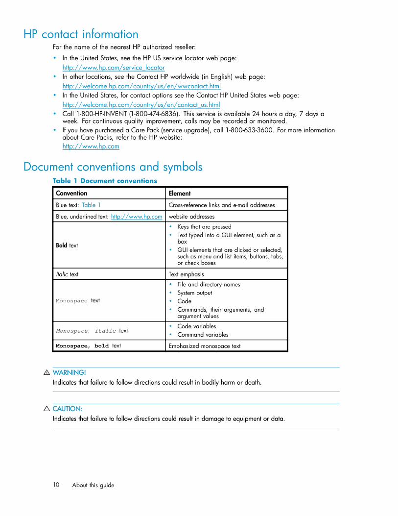
Document conventions and symbolsTable 1 Document conventions
Convention Element
Blue text: Table 1 Cross-reference links and e-mail addresses
Blue, underlined text: http://www.hp.com website addresses
Bold text
• Keys that are pressed• Text typed into a GUI element, such as a
box• GUI elements that are clicked or selected,
such as menu and list items, buttons, tabs,or check boxes
Italic text Text emphasis
Monospace text
• File and directory names• System output• Code• Commands, their arguments, and
argument values
Monospace, italic text• Code variables• Command variables
Monospace, bold text Emphasized monospace text
WARNING!Indicates that failure to follow directions could result in bodily harm or death.
CAUTION:Indicates that failure to follow directions could result in damage to equipment or data.
10 About this guide
IMPORTANT:Provides clarifying information or specific instructions.
NOTE:Provides additional information.
TIP:Provides helpful hints and shortcuts.
Subscription serviceHP strongly recommends that customers register online using the Subscriber's choice website:http://www.hp.com/go/e-updates.
Subscribing to this service provides you with e-mail updates on the latest product enhancements, newestdriver versions, and firmware documentation updates as well as instant access to numerous other productresources.
After subscribing, locate your products by selecting Business support and then Storage under ProductCategory.
Other HP websitesFor additional information, see the following HP websites:
• http://www.hp.com• http://www.hp.com/go/storage• http://www.hp.com/service_locator• http://www.docs.hp.com• http://welcome.hp.com/country/us/en/prodserv/servers.html
Documentation feedbackHP welcomes your feedback.
To make comments and suggestions about product documentation, please send a message [email protected]. All submissions become the property of HP.
Brocade 8Gb SAN Switch for HP BladeSystem c-Class 11

12 About this guide
1 Overview
The Brocade 8Gb SAN Switch for HP BladeSystem c-Class (referred to in the rest of this manual as the8Gb SAN Switch) is a Fibre Channel (FC) switch that supports link speeds of up to 8 Gbps. The 8GbSAN Switch can operate in a fabric containing multiple switches or as the only switch in a fabric.
NOTE:In this document, the Brocade 8Gb SAN Switch refers to those Brocade FC switch modules compatiblewith the HP BladeSystem c-Class enclosure only.
This chapter provides the following information:
• 8Gb SAN Switch features, page 13• ISL trunking groups, page 16• Supported optional software, page 16• Additional software features in HP BladeSystem c-Class Power Pack+ models, page 16• Supported SFP transceiver options, page 17
8Gb SAN Switch featuresThe 8Gb SAN Switch provides the following features:
• Fully integrated, embedded FC SAN design that connects directly to the HP BladeSystem c-Classenclosure midplane
• Dynamic Ports on Demand (DPOD), which automatically detects port connections, assigns portlicenses, and enables ports
• Easy-to-manage HP Storage Essentials Systems Insight Manager support• Full compatibility with HP StorageWorks B-Series switches and Brocade fabrics• Sixteen internal 1/2/4/8 Gbps auto-sensing Small Form-factor Pluggable (SFPs) with the
following characteristics:• Independent automatic negotiation to the highest common speed for each server FC port
connected to the switch• Universal self-configuring ports, which are capable of becoming F_Ports (fabric enabled)
• Eight external 1/2/4/8 Gbps FC SFP ports, with the following characteristics:• Automatic negotiation to the highest common speed of all devices connected to the port• Port-interface-compatible SFP transceivers, both short-wavelength (SWL) and long wavelength
(LWL)• Universal self-configuring ports, which are capable of becoming F_Ports, FL_Ports (fabric
loop enabled), or E_Ports (expansion ports)• Heterogeneous support for mixed storage fabrics• Power supplied and controlled by the BladeSystem enclosure• Identification to HP chassis management with HP specified SEEPROMs• Hot-swap capability• Compatibility with redundant and dual redundant switch configurations in c-Class BladeSystem• Hot code activation• Real-time clock• SFP port monitoring
Brocade 8Gb SAN Switch for HP BladeSystem c-Class 13
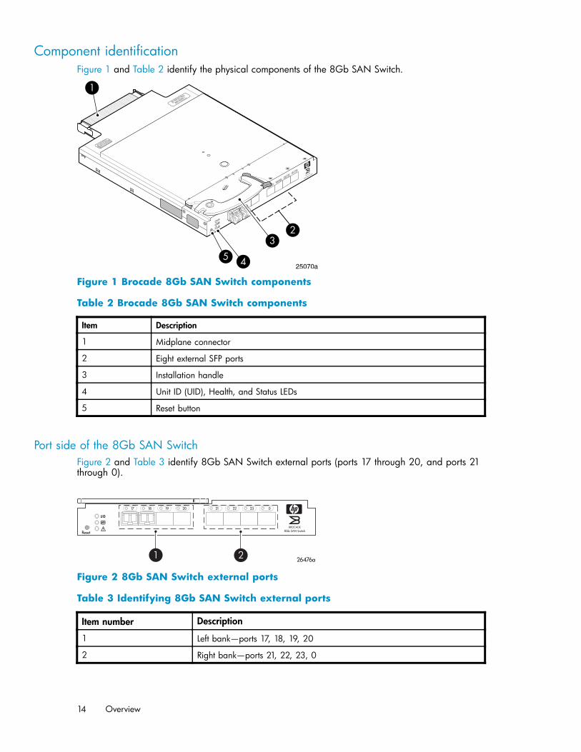
Component identificationFigure 1 and Table 2 identify the physical components of the 8Gb SAN Switch.
scale: 3/8" = 1"
21
22
23
0
17
18
19
20
!
80-100074-01 Rev.C
WH0 40000211
MAC 00 05 1E 35 A2 D6
WWN 10:00:00:05:1E:35:A2:D6
Reset
4Gb SAN SwitchBROCADE
25070a
3
1
5 4
2
Figure 1 Brocade 8Gb SAN Switch components
Table 2 Brocade 8Gb SAN Switch components
Item Description
1 Midplane connector
2 Eight external SFP ports
3 Installation handle
4 Unit ID (UID), Health, and Status LEDs
5 Reset button
Port side of the 8Gb SAN SwitchFigure 2 and Table 3 identify 8Gb SAN Switch external ports (ports 17 through 20, and ports 21through 0).
nl
scale: .667" = 1"
21 22 23 017 18 19 20
!
Reset 8Gb SAN SwitchBROCADE
26476a1 2
Figure 2 8Gb SAN Switch external ports
Table 3 Identifying 8Gb SAN Switch external ports
Item number Description
1 Left bank—ports 17, 18, 19, 20
2 Right bank—ports 21, 22, 23, 0
14 Overview
NOTE:Refer to Interpreting LED activity, page 34 for complete information on 8Gb SAN Switch LEDs.
Internal ports summarySixteen logical internal ports (numbered 1 through 16) connect sequentially to server bays 1 through 16with the enclosure midplane. Server bay 1 is connected to Switch Port 1, Server bay 2 is connected toSwitch port 2, and so forth.
8Gb SAN Switch redundancyThe HP BladeSystem c-Class was engineered as a no-single-point-of-failure bladed solution. Attributes thatcontribute to switch redundancy include:• Redundant power and cooling• Redundant HP Onboard Administrator (OA) to ensure management access to the switch
NOTE:The HP Onboard Administrator is the enclosure management module used to support and manage the HPBladeSystem c-Class and all managed devices used in the enclosure.
8Gb SAN Switch licensingThe 8Gb SAN Switch integrates one of three license options that complement existing HP product lines.Some 8Gb SAN Switch models ship with licenses that place limits on the number of domains that can beused. Models and their specific licenses are as follows:
• Brocade 8/12 SAN Switch for HP BladeSystem c-Class, base, integrating 12 active ports (in anycombination of internal/external ports) and two short-wavelength SFPs. Software componentsinclude a Full Fabric license, the Advanced Web Tools GUI and Zoning software
• Brocade 8/24 SAN Switch for HP BladeSystem c-Class, base, integrating 24 active ports (16internal and 8 external) and four short-wavelength SFPs. Software components include a FullFabric license, Advanced Web Tools GUI, and Zoning software
• Brocade 8/24 Gb SAN Switch for HP BladeSystem c-Class, Power Pack, integrating 24 activeports (16 internal and 8 external) and four short-wavelength SFPs. Software components includea Full Fabric license, Advanced Web Tools GUI, and Zoning software plus these additionalsoftware features:• Fabric Watch• ISL Trunking• Advanced Performance Monitoring (APM)• Extended Fabric
IMPORTANT:Upgrade the 8Gb SAN Switch by purchasing optional licenses; access the latest version of the HPStorageWorks Fabric OS administrator guide to learn how to add a license.
Brocade 8Gb SAN Switch for HP BladeSystem c-Class 15
ISL trunking groupsIf your 8Gb SAN Switch is licensed for interswitch link (ISL) trunking, use the trunking groups available onthe switch.
The FC ports are numbered from left to right, and are part of the same ISL trunking group. The trunkinggroup consists of the ports shown in Figure 2.
NOTE:ISL Trunking is optional software that allows you to create trunking groups of ISLs between adjacentswitches. ISL trunking is available on the Brocade 8Gb SAN Switch for HP BladeSystem c-Class PowerPack+ model, or by purchasing the optional license described in ???. For more information abouttrunking, refer to the latest version of the HP StorageWorks Fabric OS administrator guide.
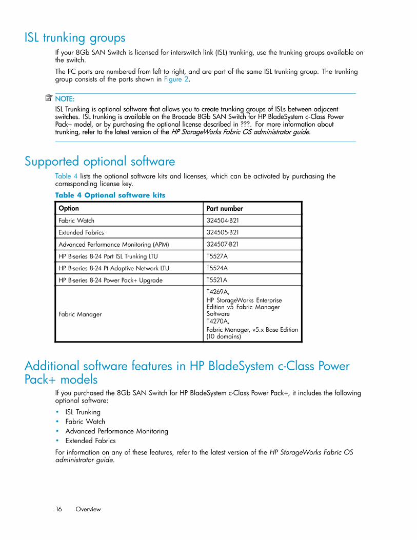
Supported optional softwareTable 4 lists the optional software kits and licenses, which can be activated by purchasing thecorresponding license key.
Table 4 Optional software kits
Option Part number
Fabric Watch 324504-B21
Extended Fabrics 324505-B21
Advanced Performance Monitoring (APM) 324507-B21
HP B-series 8-24 Port ISL Trunking LTU T5527A
HP B-series 8-24 Pt Adaptive Network LTU T5524A
HP B-series 8-24 Power Pack+ Upgrade T5521A
Fabric Manager
T4269A,nl
HP StorageWorks EnterpriseEdition v5 Fabric ManagerSoftwarenl
T4270A,nl
Fabric Manager, v5.x Base Edition(10 domains)
Additional software features in HP BladeSystem c-Class PowerPack+ models
If you purchased the 8Gb SAN Switch for HP BladeSystem c-Class Power Pack+, it includes the followingoptional software:
• ISL Trunking• Fabric Watch• Advanced Performance Monitoring• Extended Fabrics
For information on any of these features, refer to the latest version of the HP StorageWorks Fabric OSadministrator guide.
16 Overview
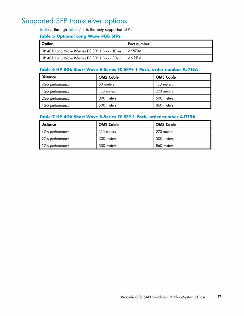
Supported SFP transceiver optionsTable 5 through Table 7 lists the only supported SFPs.
Table 5 Optional Long Wave 4Gb SFPs
Option Part number
HP 4Gb Long Wave B-Series FC SFP 1 Pack - 10km AK870A
HP 4Gb Long Wave B-Series FC SFP 1 Pack - 30km AN211A
Table 6 HP 8Gb Short Wave B-Series FC SFP+ 1 Pack, order number AJ716A
Distance OM2 Cable OM3 Cable
8Gb performance 50 meters 150 meters
4Gb performance 150 meters 270 meters
2Gb performance 300 meters 500 meters
1Gb performance 500 meters 860 meters
Table 7 HP 4Gb Short Wave B-Series FC SFP 1 Pack, order number AJ715A
Distance OM2 Cable OM3 Cable
4Gb performance 150 meters 270 meters
2Gb performance 300 meters 500 meters
1Gb performance 500 meters 860 meters
Brocade 8Gb SAN Switch for HP BladeSystem c-Class 17

18 Overview

2 Setup
This chapter provides the following information:
• Shipping carton contents, page 19• Installation and safety considerations, page 20• Install the 8Gb SAN Switch, page 20• Set the IP address, page 23• Configure the 4Gb SAN Switch, page 25
Shipping carton contentsFigure 3 and Table 8 identify the 8Gb SAN Switch shipping carton contents:
• Brocade 8Gb SAN Switch for HP BladeSystem c-Class installation instructions• SFP dust covers (must be inserted in ports where Small Form-factor Pluggable (SFP) optical
transceivers are not installed)• Four Short Wavelengh (SWL) 8Gb SFPs, (in styrofoam packing)• One Brocade 8Gb SAN Switch; models include:
• Brocade 8/12 SAN Switch for HP BladeSystem c-Class with twelve active ports• Brocade 8/24 SAN Switch for HP BladeSystem c-Class with sixteen internal and eight external
active ports• Brocade 8/24 SAN Switch Power Pack+ for HP BladeSystem c-Class with sixteen internal and
eight external active ports
scale: 3/8" = 1"
21
22
23
0
17
18
19
20
!
80-100074-01 Rev.C
WH0 40000211
MAC 00 05 1E 35 A2 D6
WWN 10:00:00:05:1E:35:A2:D6
Reset
b SAN Switch
26480a
3
1
2
Figure 3 Carton contents
Table 5 identifies 8Gb SAN Switch components.
Table 8 Brocade 8Gb SAN Switch components
Item Description
1 Brocade 8Gb SAN Switch, ships with four Short Wavelengh (SWL) 8Gb SFPs, (instyrofoam packing)
2 Dust covers for empty SFP ports
3 Brocade 8Gb SAN Switch for HP BladeSystem c-Class installation instructions
Brocade 8Gb SAN Switch for HP BladeSystem c-Class 19
Installation and safety considerationsThe 8Gb SAN Switch installs in the I/O bays in the rear of the HP BladeSystem c-Class enclosure. Refer tothe appropriate BladeSystem Enclosure Setup and Installation Guide for specific enclosure requirements.
Installing multiple switchesIf you do not have a DHCP server connected to the OA, install and configure one 8Gb SAN Switch at atime. This is required so that Ethernet IP address conflicts do not occur with duplicate default Ethernet IPaddresses.
IMPORTANT:DHCP is enabled by default on this switch. In cases where DHCP is available, IP address conflicts will notoccur, simplifying multiple switch installations. See Using external DHCP, page 24.
Each switch must be assigned a unique Ethernet IP address during configuration. Once the defaultEthernet IP address on the 8Gb SAN Switch has been changed, you may install additional 8Gb SANSwitches in the enclosure.
See the appropriate HP BladeSystem Enclosure Setup and Installation Guide for help identifying yourspecific enclosure setup, available connections, and power requirements.
Electrical considerationsThe 8Gb SAN Switch requires 35 watts, provided by the enclosure. No other power requirement orprovision exists.
Environmental considerationsEnsure proper cooling and ventilation by verifying the following:
• The air vents on the enclosure are not blocked or restricted.• The ambient air temperature at the front of the enclosure does not exceed 35°C (95°F) while the
switch is operating.
IMPORTANT:The dust covers that ship with your 8Gb SAN Switch must be inserted into any ports where SFPs arenot installed, to help contain air flow in the BladeSystem chassis.
Install the 8Gb SAN SwitchInstall the Brocade 8Gb SAN Switch into the enclosure:
1. Locate the appropriate interconnect bay in the rear of the enclosure as specified in the appropriateHP BladeSystem Enclosure Setup and Installation Guide provided with your enclosure.
IMPORTANT:Populate all enclosure I/O bays with the appropriate component (for example a switch,Pass-Thru, or one of the blank panels provided with the enclosure).
20 Setup
2. Remove the slot cover (if installed).
CAUTION:Properly ground yourself before handling the switch.
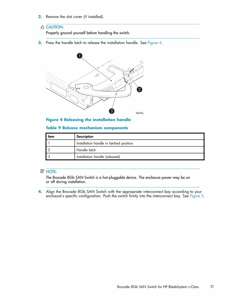
3. Press the handle latch to release the installation handle. See Figure 4.
scale: 2/3" = 1"
21
22
23
17
18
19
20
!
Reset
26475a
2
3
1
Figure 4 Releasing the installation handle
Table 9 Release mechanism components
Item Description
1 Installation handle in latched position
2 Handle latch
3 Installation handle (released)
NOTE:The Brocade 8Gb SAN Switch is a hot-pluggable device. The enclosure power may be onor off during installation.
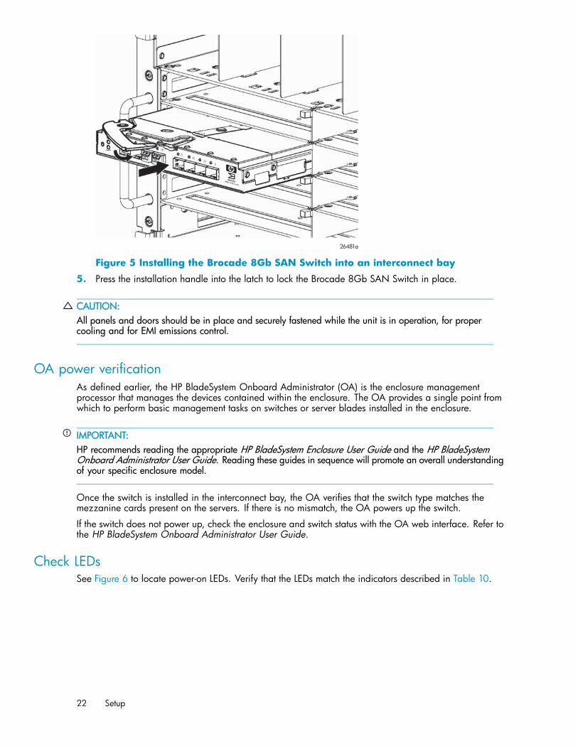
4. Align the Brocade 8Gb SAN Switch with the appropriate interconnect bay according to yourenclosure’s specific configuration. Push the switch firmly into the interconnect bay. See Figure 5.
Brocade 8Gb SAN Switch for HP BladeSystem c-Class 21
26481a
20
2122
230
Figure 5 Installing the Brocade 8Gb SAN Switch into an interconnect bay
5. Press the installation handle into the latch to lock the Brocade 8Gb SAN Switch in place.
CAUTION:All panels and doors should be in place and securely fastened while the unit is in operation, for propercooling and for EMI emissions control.
OA power verificationAs defined earlier, the HP BladeSystem Onboard Administrator (OA) is the enclosure managementprocessor that manages the devices contained within the enclosure. The OA provides a single point fromwhich to perform basic management tasks on switches or server blades installed in the enclosure.
IMPORTANT:HP recommends reading the appropriate HP BladeSystem Enclosure User Guide and the HP BladeSystemOnboard Administrator User Guide. Reading these guides in sequence will promote an overall understandingof your specific enclosure model.
Once the switch is installed in the interconnect bay, the OA verifies that the switch type matches themezzanine cards present on the servers. If there is no mismatch, the OA powers up the switch.
If the switch does not power up, check the enclosure and switch status with the OA web interface. Refer tothe HP BladeSystem Onboard Administrator User Guide.
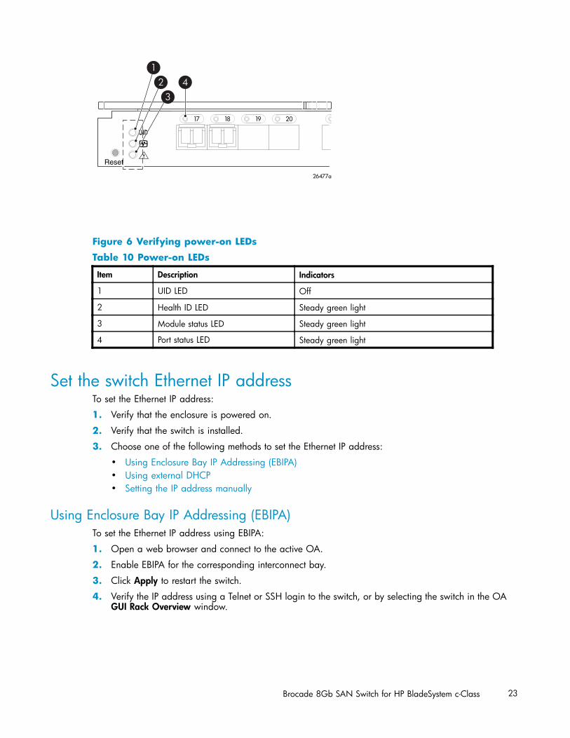
Check LEDsSee Figure 6 to locate power-on LEDs. Verify that the LEDs match the indicators described in Table 10.
22 Setup
scale: 1" = 1"
17 18 19 20
!
Reset
26477a
12
34
Figure 6 Verifying power-on LEDs
Table 10 Power-on LEDs
Item Description Indicators
1 UID LED Off
2 Health ID LED Steady green light
3 Module status LED Steady green light
4 Port status LED Steady green light
Set the switch Ethernet IP addressTo set the Ethernet IP address:
1. Verify that the enclosure is powered on.
2. Verify that the switch is installed.
3. Choose one of the following methods to set the Ethernet IP address:
• Using Enclosure Bay IP Addressing (EBIPA)• Using external DHCP• Setting the IP address manually
Using Enclosure Bay IP Addressing (EBIPA)To set the Ethernet IP address using EBIPA:
1. Open a web browser and connect to the active OA.
2. Enable EBIPA for the corresponding interconnect bay.
3. Click Apply to restart the switch.
4. Verify the IP address using a Telnet or SSH login to the switch, or by selecting the switch in the OAGUI Rack Overview window.
Brocade 8Gb SAN Switch for HP BladeSystem c-Class 23
NOTE:Refer to the HP BladeSystem Onboard Administrator user guide for additional information on EBIPA.
Using external DHCPTo set the Ethernet IP address using external DHCP:
1. Connect to the active OA with a web browser.
2. Document the DHCP-assigned address by selecting the switch from the OA GUI Rack Overviewwindow.
3. Verify the IP address using a Telnet or SSH login to the switch, or select the switch in the OA GUIRack Overview window.
Setting the IP address manuallyTo set the IP address manually:
NOTE:As an alternate method to using a null modem cable, use Telnet or SSH to access the IP address of theOnboard Administrator, resuming at step 9 below.
1. Obtain the following items to set the IP address with a serial connection:
• Computer with a terminal application (such as HyperTerminal in a Windows environmentor TERM in a UNIX environment)
• Null modem serial cable2. Replace the default IP address (if present) and related information with the information provided
by your network administrator. By default, the IP address is set to 10.77.77.77 for switches withrevision levels earlier than 0C.
3. Verify that the enclosure is powered on.
4. Identify the active OA in the BladeSystem.
5. Connect a null modem serial cable from your computer to the serial port of the active OA.
6. Configure the terminal application as follows:In a Windows environment, enter:• Bits per second—9600• Databits—8• Parity—None• Stop bits—1• Flow control—None
In a UNIX environment, enter: tip /dev/ttyb –9600
7. Log in to the OA.
8. Press Enter to display the switch console.
24 Setup
9. Identify the interconnect bay number where the switch is installed. At the OA command line, enter:
connect interconnect x
Where x is the interconnect bay slot where the switch is installed.
a. User: admin
b. Password: password
NOTE:Enter entries as shown, because commands are case sensitive.
10. Or, follow the onscreen prompts to change your password now.
11. The OA will then connect its serial line to the Switch in the specified interconnect bay. A promptdisplays indicating that the escape character for returning to the OA is Ctrl __ (underscore).
12. At the command line, enter: ipaddrset.
13. Enter the remaining IP addressing information, as prompted.
14. Optionally, enter ipaddrshow at the command prompt to verify that the IP address is set correctly.
15. Record the IP addressing information, and store it in a safe place.
16. Enter Exit, and press Enter to log out of the serial console.
17. Disconnect the serial cable. For additional assistance with operating the Onboard AdministratorCLI, refer to the Onboard Administrator Command Line Interface user guide for your specificenclosure, available at http://www.hp.com.
Configure the 8Gb SAN SwitchThe 8Gb SAN Switch must be configured to ensure correct operation within a network and fabric. Forinstructions about configuring the switch to operate in a fabric containing switches from other vendors,refer to the HP StorageWorks SAN Design reference guide:
http://h18000.www1.hp.com/products/storageworks/san/documentation.html.
For more information about the CLI, refer to the latest version of the Fabric OS command reference guide.
Items required for configurationThe following items are required for configuring and connecting the 8Gb SAN Switch for use in anetwork and fabric:
• 8Gb SAN Switch installed in the enclosure• IP address and corresponding subnet mask and gateway address recorded during the
Set the IP address, page 23 procedure• Ethernet cable• SFP transceivers and compatible optical cables, as required• Access to an FTP server for backing up the switch configuration (optional)
Connect to the Command Line InterfaceMake an Ethernet connection and log in to the 8Gb SAN Switch:
Brocade 8Gb SAN Switch for HP BladeSystem c-Class 25
1. Connect the workstation to the Ethernet network containing the OA. If the OA is not on a network,connect directly to the OA/iLO Ethernet port on the active OA.
IMPORTANT:Verify that the switch is not being reconfigured from any other connections during the remaining steps.
2. Open a Telnet connection using the IP address set earlier. The login prompt displays when the Telnetconnection locates the switch in the network.
3. Enter the user name, using the administrative account admin.
4. Enter the password. The default password is password.
NOTE:You can run up to two simultaneous admin sessions and four user sessions.
If you have not changed the system passwords from the default, you are prompted to change them.Enter the new system passwords, or press Ctrl-c to skip the password prompts.
5. Verify that the login was successful. If successful, the prompt displays the switch name and user ID towhich you are connected.
Setting the date and timeThe date and time are used for logging events. 8Gb SAN Switch operation does not depend on the dateand time; a switch with an incorrect date and time value will function properly.
To set the date and time using the CLI:
1. If you have not already done so, connect to the switch and log in as admin as described inConnect to the Command Line Interface, page 25.
2. Issue the date command using the following syntax:
date mmddHHMMyy”
where:• mm is the month; valid values are 01 through 12.• dd is the date; valid values are 01 through 31.• HH is the hour; valid values are 00 through 23.• MM is minutes; valid values are 00 through 59.• yy is the year; valid values are 00 through 99 (values greater than 69 are interpreted as
1970–1999, and values less than 70 are interpreted as 2000–2069).For example:switch:admin> datenl
Fri Jan 29 17:01:48 UTC 2000nl
switch:admin> date 0227123003nl
Thu Feb 27 12:30:00 UTC 2003nl
switch:admin>
For details about changing time zones, see the tsTimeZone command in the latest version of theFabric OS command reference guide.
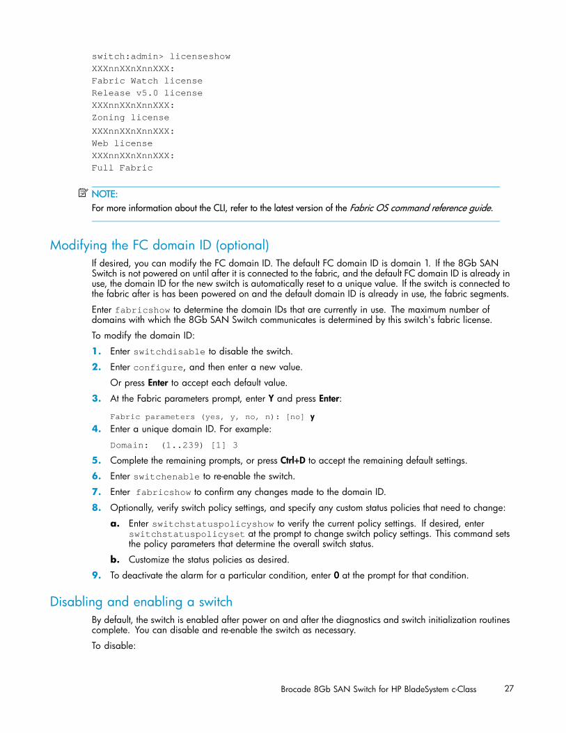
Verifying installed licensesTo determine the type of licensing included with your 8Gb SAN Switch, enter licenseshow at thecommand prompt, as in the following example:
26 Setup
nl
switch:admin> licenseshownlnl
XXXnnXXnXnnXXX:nlnl
Fabric Watch licensenlnl
Release v5.0 licensenlnl
XXXnnXXnXnnXXX:nlnl
Zoning licensenlnl
XXXnnXXnXnnXXX:nlnl
Web licensenlnl
XXXnnXXnXnnXXX:nlnl
Full Fabric
NOTE:For more information about the CLI, refer to the latest version of the Fabric OS command reference guide.
Modifying the FC domain ID (optional)If desired, you can modify the FC domain ID. The default FC domain ID is domain 1. If the 8Gb SANSwitch is not powered on until after it is connected to the fabric, and the default FC domain ID is already inuse, the domain ID for the new switch is automatically reset to a unique value. If the switch is connected tothe fabric after is has been powered on and the default domain ID is already in use, the fabric segments.
Enter fabricshow to determine the domain IDs that are currently in use. The maximum number ofdomains with which the 8Gb SAN Switch communicates is determined by this switch's fabric license.
To modify the domain ID:
1. Enter switchdisable to disable the switch.
2. Enter configure, and then enter a new value.
Or press Enter to accept each default value.
3. At the Fabric parameters prompt, enter Y and press Enter:
Fabric parameters (yes, y, no, n): [no] y4. Enter a unique domain ID. For example:
Domain: (1..239) [1] 3
5. Complete the remaining prompts, or press Ctrl+D to accept the remaining default settings.
6. Enter switchenable to re-enable the switch.
7. Enter fabricshow to confirm any changes made to the domain ID.
8. Optionally, verify switch policy settings, and specify any custom status policies that need to change:
a. Enter switchstatuspolicyshow to verify the current policy settings. If desired, enterswitchstatuspolicyset at the prompt to change switch policy settings. This command setsthe policy parameters that determine the overall switch status.
b. Customize the status policies as desired.
9. To deactivate the alarm for a particular condition, enter 0 at the prompt for that condition.
Disabling and enabling a switchBy default, the switch is enabled after power on and after the diagnostics and switch initialization routinescomplete. You can disable and re-enable the switch as necessary.
To disable:
Brocade 8Gb SAN Switch for HP BladeSystem c-Class 27
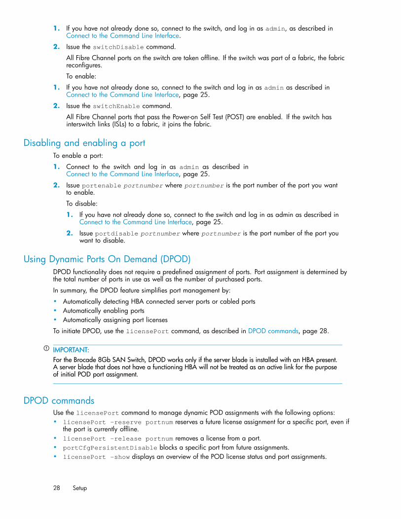
1. If you have not already done so, connect to the switch, and log in as admin, as described inConnect to the Command Line Interface.
2. Issue the switchDisable command.
All Fibre Channel ports on the switch are taken offline. If the switch was part of a fabric, the fabricreconfigures.
To enable:
1. If you have not already done so, connect to the switch and log in as admin as described inConnect to the Command Line Interface, page 25.
2. Issue the switchEnable command.
All Fibre Channel ports that pass the Power-on Self Test (POST) are enabled. If the switch hasinterswitch links (ISLs) to a fabric, it joins the fabric.
Disabling and enabling a portTo enable a port:
1. Connect to the switch and log in as admin as described inConnect to the Command Line Interface, page 25.
2. Issue portenable portnumber where portnumber is the port number of the port you wantto enable.
To disable:
1. If you have not already done so, connect to the switch and log in as admin as described inConnect to the Command Line Interface, page 25.
2. Issue portdisable portnumber where portnumber is the port number of the port youwant to disable.
Using Dynamic Ports On Demand (DPOD)DPOD functionality does not require a predefined assignment of ports. Port assignment is determined bythe total number of ports in use as well as the number of purchased ports.
In summary, the DPOD feature simplifies port management by:
• Automatically detecting HBA connected server ports or cabled ports• Automatically enabling ports• Automatically assigning port licenses
To initiate DPOD, use the licensePort command, as described in DPOD commands, page 28.
IMPORTANT:For the Brocade 8Gb SAN Switch, DPOD works only if the server blade is installed with an HBA present.A server blade that does not have a functioning HBA will not be treated as an active link for the purposeof initial POD port assignment.
DPOD commandsUse the licensePort command to manage dynamic POD assignments with the following options:• licensePort –reserve portnum reserves a future license assignment for a specific port, even if
the port is currently offline.• licensePort –release portnum removes a license from a port.• portCfgPersistentDisable blocks a specific port from future assignments.• licensePort -show displays an overview of the POD license status and port assignments.
28 Setup
nl
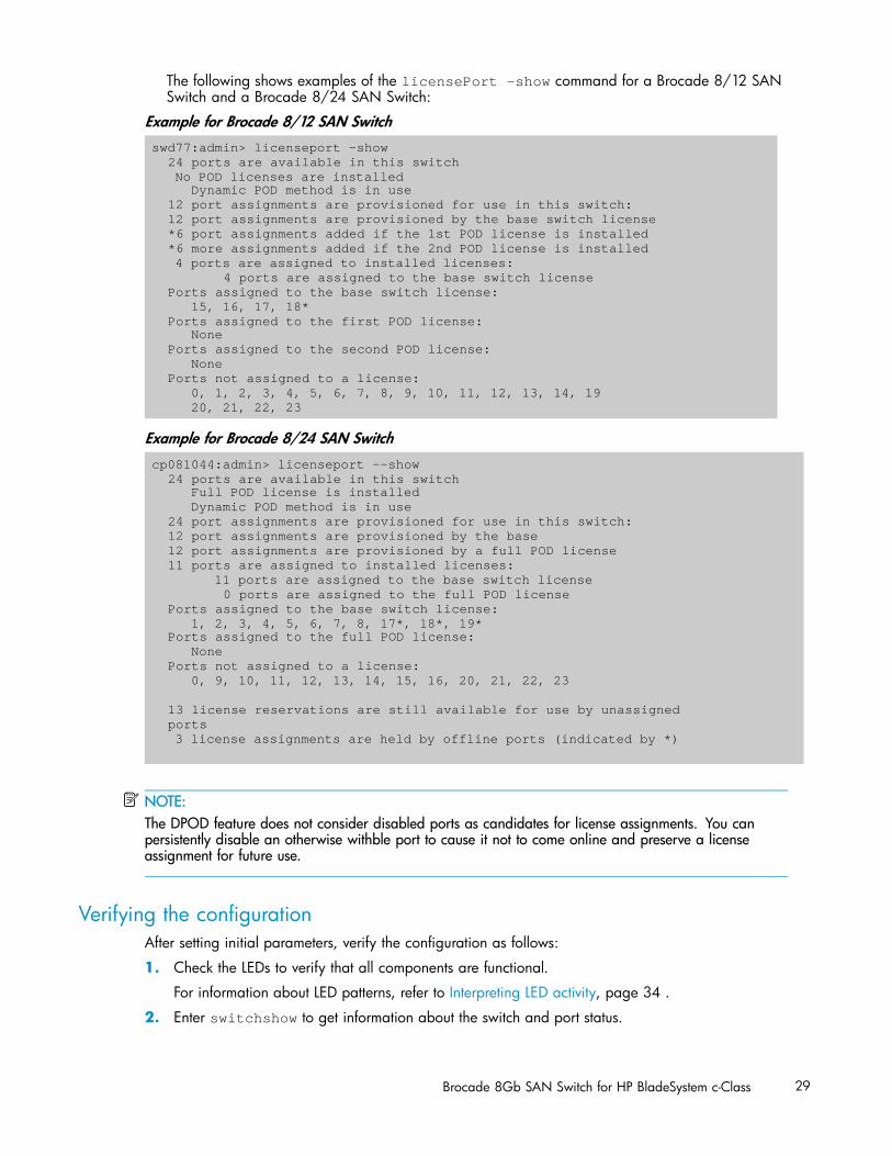
The following shows examples of the licensePort -show command for a Brocade 8/12 SANSwitch and a Brocade 8/24 SAN Switch:
Example for Brocade 8/12 SAN Switchswd77:admin> licenseport -show
24 ports are available in this switchNo POD licenses are installed
Dynamic POD method is in use12 port assignments are provisioned for use in this switch:12 port assignments are provisioned by the base switch license*6 port assignments added if the 1st POD license is installed*6 more assignments added if the 2nd POD license is installed
4 ports are assigned to installed licenses:4 ports are assigned to the base switch license
Ports assigned to the base switch license:15, 16, 17, 18*
Ports assigned to the first POD license:None
Ports assigned to the second POD license:None
Ports not assigned to a license:0, 1, 2, 3, 4, 5, 6, 7, 8, 9, 10, 11, 12, 13, 14, 1920, 21, 22, 23
Example for Brocade 8/24 SAN Switchcp081044:admin> licenseport --show
24 ports are available in this switchFull POD license is installedDynamic POD method is in use
24 port assignments are provisioned for use in this switch:12 port assignments are provisioned by the base12 port assignments are provisioned by a full POD license11 ports are assigned to installed licenses:
11 ports are assigned to the base switch license0 ports are assigned to the full POD license
Ports assigned to the base switch license:1, 2, 3, 4, 5, 6, 7, 8, 17*, 18*, 19*
Ports assigned to the full POD license:None
Ports not assigned to a license:0, 9, 10, 11, 12, 13, 14, 15, 16, 20, 21, 22, 23
13 license reservations are still available for use by unassignedports
3 license assignments are held by offline ports (indicated by *)
NOTE:The DPOD feature does not consider disabled ports as candidates for license assignments. You canpersistently disable an otherwise withble port to cause it not to come online and preserve a licenseassignment for future use.
Verifying the configurationAfter setting initial parameters, verify the configuration as follows:
1. Check the LEDs to verify that all components are functional.
For information about LED patterns, refer to Interpreting LED activity, page 34 .
2. Enter switchshow to get information about the switch and port status.
Brocade 8Gb SAN Switch for HP BladeSystem c-Class 29

3. Enter fabricshow to get general information about the fabric.
Backing up the configurationTo back up the switch configuration to an FTP server, enter configupload and follow the prompts.The configupload command copies the switch configuration to the server, making it available fordownloading to a replacement switch, if necessary.
30 Setup
3 Managing the 8Gb SAN Switch
This chapter provides the following information:
• Management features, page 31• Maintaining the 8Gb SAN Switch, page 32• Powering on and off, page 33• Interpreting LED activity, page 34• LED patterns, page 34• POST and boot specifications, page 36• Firmware update, page 37• About the reset button, page 37• Replacing a faulty 8Gb SAN Switch
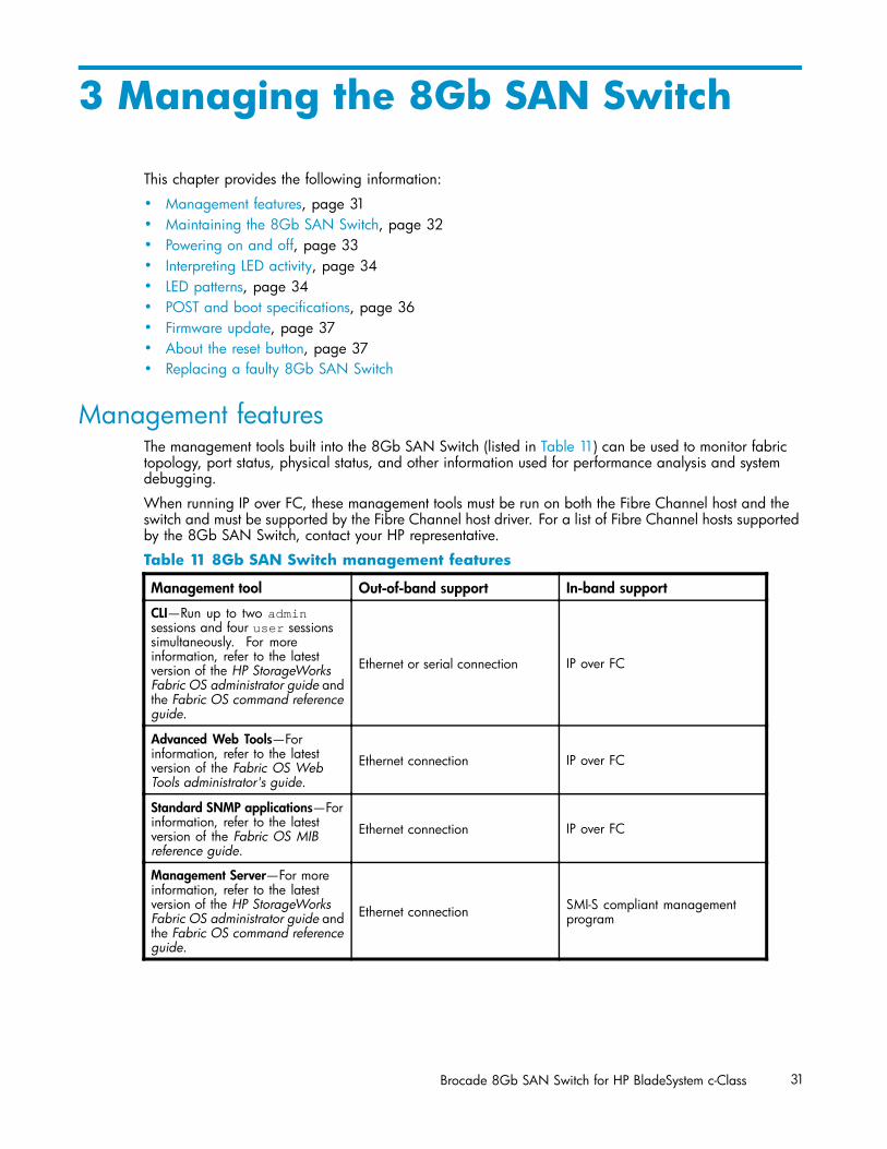
Management featuresThe management tools built into the 8Gb SAN Switch (listed in Table 11) can be used to monitor fabrictopology, port status, physical status, and other information used for performance analysis and systemdebugging.
When running IP over FC, these management tools must be run on both the Fibre Channel host and theswitch and must be supported by the Fibre Channel host driver. For a list of Fibre Channel hosts supportedby the 8Gb SAN Switch, contact your HP representative.
Table 11 8Gb SAN Switch management features
Management tool Out-of-band support In-band support
CLI—Run up to two adminsessions and four user sessionssimultaneously. For moreinformation, refer to the latestversion of the HP StorageWorksFabric OS administrator guide andthe Fabric OS command referenceguide.
Ethernet or serial connection IP over FC
Advanced Web Tools—Forinformation, refer to the latestversion of the Fabric OS WebTools administrator's guide.
Ethernet connection IP over FC
Standard SNMP applications—Forinformation, refer to the latestversion of the Fabric OS MIBreference guide.
Ethernet connection IP over FC
Management Server—For moreinformation, refer to the latestversion of the HP StorageWorksFabric OS administrator guide andthe Fabric OS command referenceguide.
Ethernet connection SMI-S compliant managementprogram
Brocade 8Gb SAN Switch for HP BladeSystem c-Class 31
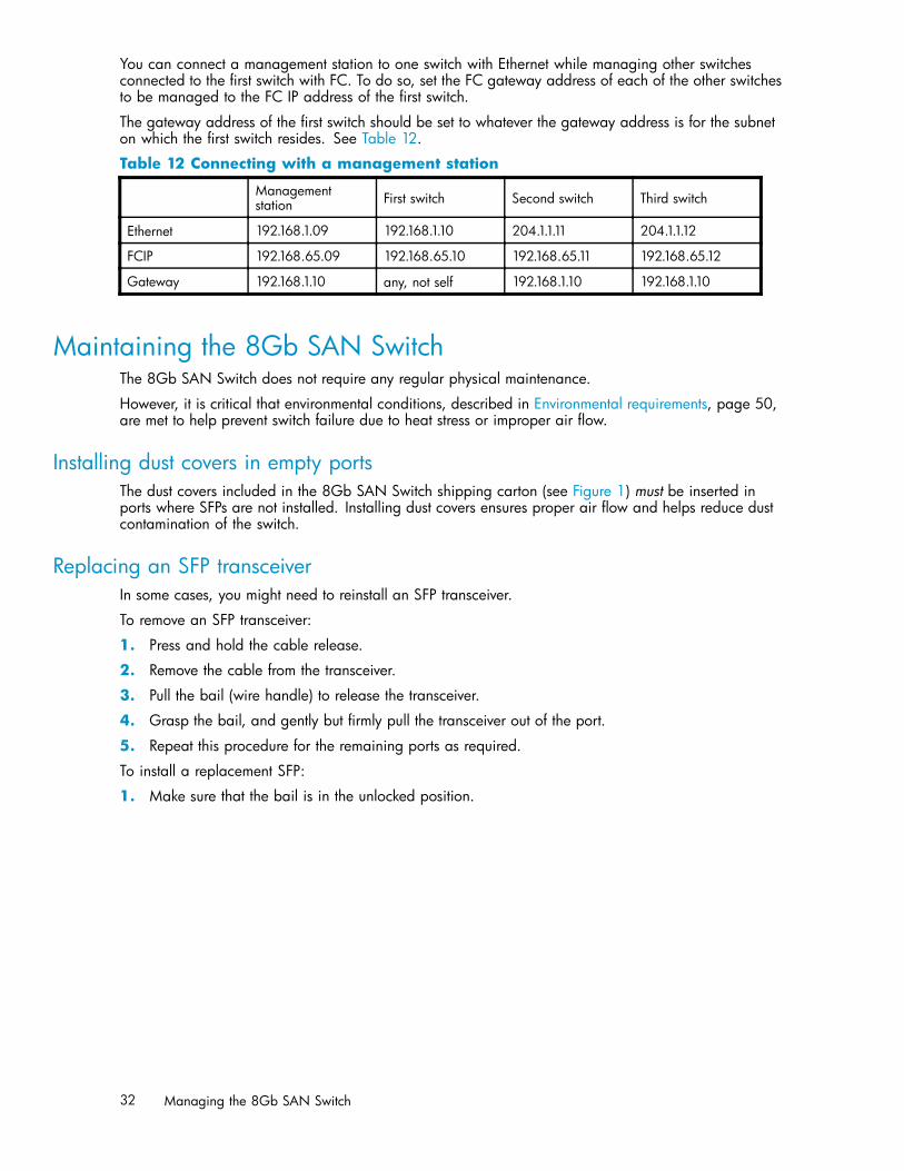
You can connect a management station to one switch with Ethernet while managing other switchesconnected to the first switch with FC. To do so, set the FC gateway address of each of the other switchesto be managed to the FC IP address of the first switch.
The gateway address of the first switch should be set to whatever the gateway address is for the subneton which the first switch resides. See Table 12.
Table 12 Connecting with a management station
Managementstation First switch Second switch Third switch
Ethernet 192.168.1.09 192.168.1.10 204.1.1.11 204.1.1.12
FCIP 192.168.65.09 192.168.65.10 192.168.65.11 192.168.65.12
Gateway 192.168.1.10 any, not self 192.168.1.10 192.168.1.10
Maintaining the 8Gb SAN SwitchThe 8Gb SAN Switch does not require any regular physical maintenance.
However, it is critical that environmental conditions, described in Environmental requirements, page 50,are met to help prevent switch failure due to heat stress or improper air flow.
Installing dust covers in empty portsThe dust covers included in the 8Gb SAN Switch shipping carton (see Figure 1) must be inserted inports where SFPs are not installed. Installing dust covers ensures proper air flow and helps reduce dustcontamination of the switch.
Replacing an SFP transceiverIn some cases, you might need to reinstall an SFP transceiver.
To remove an SFP transceiver:
1. Press and hold the cable release.
2. Remove the cable from the transceiver.
3. Pull the bail (wire handle) to release the transceiver.
4. Grasp the bail, and gently but firmly pull the transceiver out of the port.
5. Repeat this procedure for the remaining ports as required.
To install a replacement SFP:
1. Make sure that the bail is in the unlocked position.
32 Managing the 8Gb SAN Switch
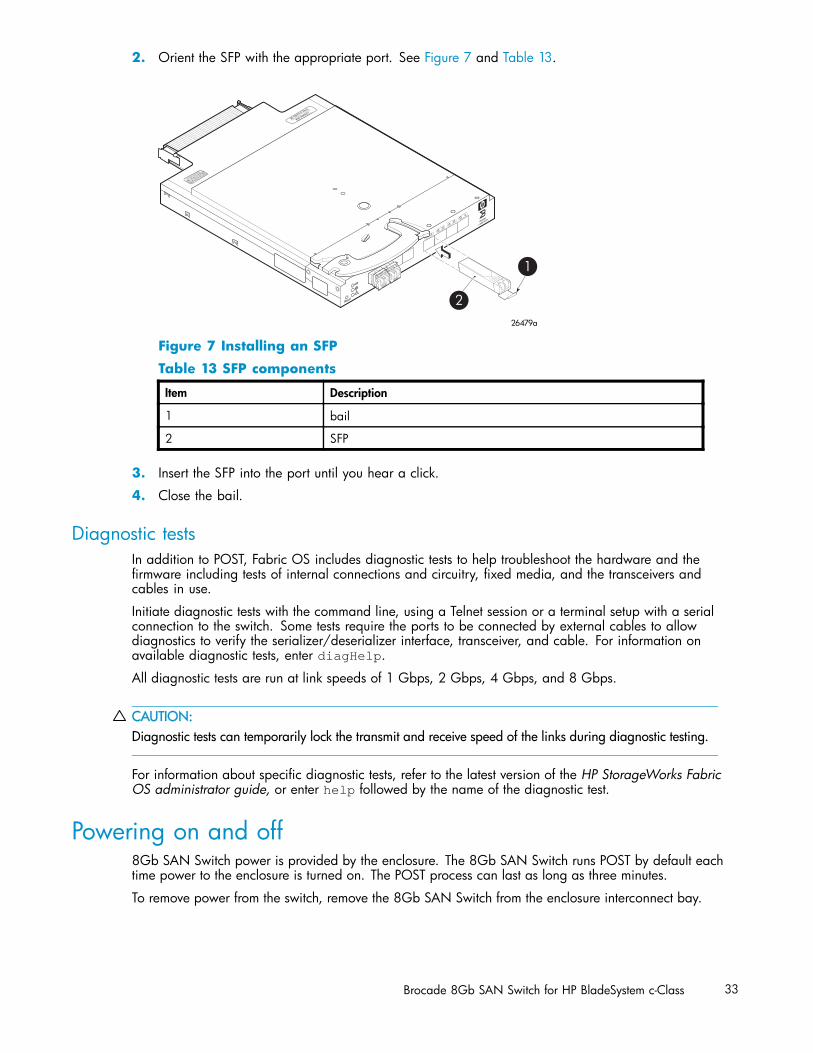
2. Orient the SFP with the appropriate port. See Figure 7 and Table 13.
scale: 3/8" = 1"
21
22
23
0
17
18
19
20
!
80-100074-01 Rev.C
WH0 40000211
MAC 00 05 1E 35 A2 D6
WWN 10:00:00:05:1E:35:A2:D6
Reset
b SAN Switch
26479a
1
2
BROCADE
Figure 7 Installing an SFP
Table 13 SFP components
Item Description
1 bail
2 SFP
3. Insert the SFP into the port until you hear a click.
4. Close the bail.
Diagnostic testsIn addition to POST, Fabric OS includes diagnostic tests to help troubleshoot the hardware and thefirmware including tests of internal connections and circuitry, fixed media, and the transceivers andcables in use.
Initiate diagnostic tests with the command line, using a Telnet session or a terminal setup with a serialconnection to the switch. Some tests require the ports to be connected by external cables to allowdiagnostics to verify the serializer/deserializer interface, transceiver, and cable. For information onavailable diagnostic tests, enter diagHelp.
All diagnostic tests are run at link speeds of 1 Gbps, 2 Gbps, 4 Gbps, and 8 Gbps.
CAUTION:Diagnostic tests can temporarily lock the transmit and receive speed of the links during diagnostic testing.
For information about specific diagnostic tests, refer to the latest version of the HP StorageWorks FabricOS administrator guide, or enter help followed by the name of the diagnostic test.
Powering on and off8Gb SAN Switch power is provided by the enclosure. The 8Gb SAN Switch runs POST by default eachtime power to the enclosure is turned on. The POST process can last as long as three minutes.
To remove power from the switch, remove the 8Gb SAN Switch from the enclosure interconnect bay.
Brocade 8Gb SAN Switch for HP BladeSystem c-Class 33
NOTE:Each time the 8Gb SAN Switch is powered on, its settings are restored to the last saved configuration.
Interpreting LED activityYou can monitor switch activity and status by checking 8Gb SAN Switch LEDs.
There are three possible LED states: no light, a steady light, or a flashing light. The steady lights andflashing lights can be green or amber.
The LEDs flash any of these colors during boot, POST, or other diagnostic tests. This is normal anddoes not indicate a problem unless the LEDs do not indicate a healthy state after all boot processesand diagnostic tests are complete. A healthy state is indicated by a steady green light. See Table15, page 35 for details about LED activity.
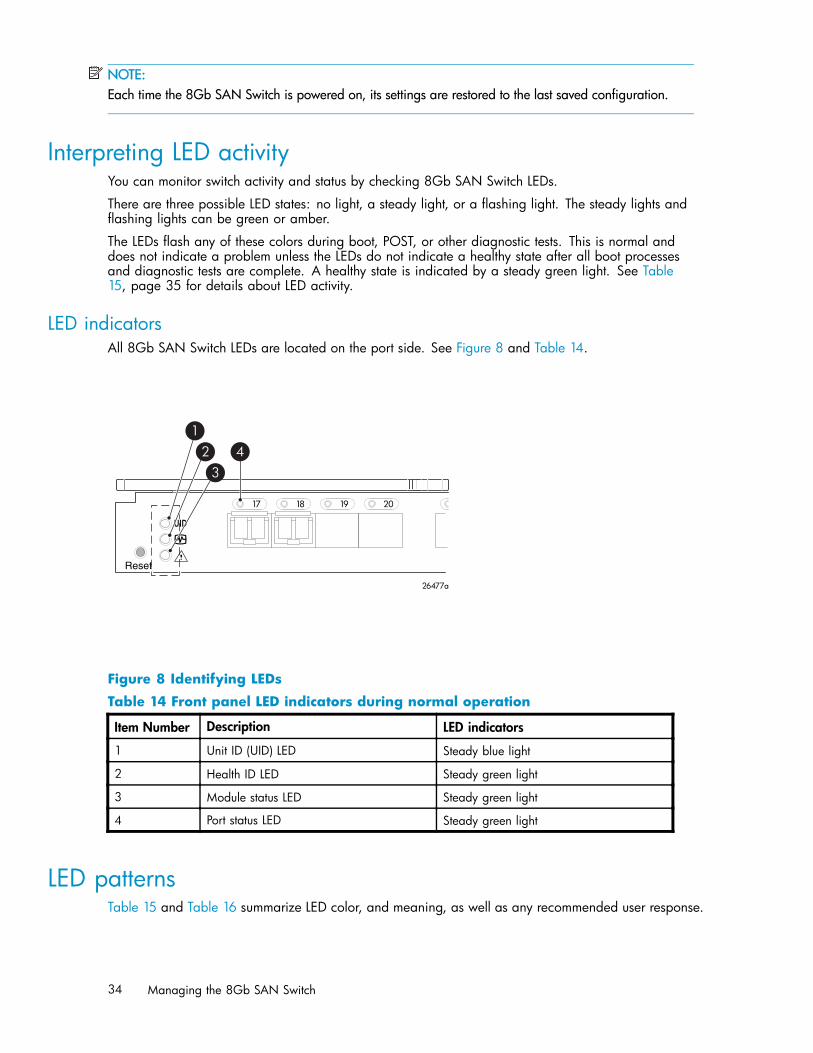
LED indicatorsAll 8Gb SAN Switch LEDs are located on the port side. See Figure 8 and Table 14.
scale: 1" = 1"
17 18 19 20
!
Reset
26477a
12
34
Figure 8 Identifying LEDs
Table 14 Front panel LED indicators during normal operation
Item Number Description LED indicators
1 Unit ID (UID) LED Steady blue light
2 Health ID LED Steady green light
3 Module status LED Steady green light
4 Port status LED Steady green light
LED patternsTable 15 and Table 16 summarize LED color, and meaning, as well as any recommended user response.
34 Managing the 8Gb SAN Switch
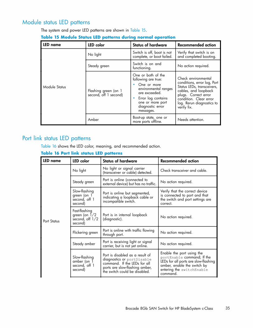
Module status LED patternsThe system and power LED patterns are shown in Table 15.
Table 15 Module Status LED patterns during normal operation
LED name LED color Status of hardware Recommended action
No light Switch is off, boot is notcomplete, or boot failed.
Verify that switch is onand completed booting.
Steady green Switch is on andfunctioning. No action required.
Flashing green (on 1second, off 1 second)
One or both of thefollowing are true:• One or more
environmental rangesare exceeded.
• Error log containsone or more portdiagnostic errormessages.
Check environmentalconditions, error log, PortStatus LEDs, transceivers,cables, and loopbackplugs. Correct errorcondition. Clear errorlog. Rerun diagnostics toverify fix.
Module Status
Amber Boot-up state, one ormore ports offline. Needs attention.
Port link status LED patternsTable 16 shows the LED color, meaning, and recommended action.
Table 16 Port link status LED patterns
LED name LED color Status of hardware Recommended action
No light No light or signal carrier(transceiver or cable) detected. Check transceiver and cable.
Steady green Port is online (connected toexternal device) but has no traffic. No action required.
Slow-flashinggreen (on 1second, off 1second)
Port is online but segmented,indicating a loopback cable orincompatible switch.
Verify that the correct deviceis connected to port and thatthe switch and port settings arecorrect.
Fast-flashinggreen (on 1/2second, off 1/2second)
Port is in internal loopback(diagnostic). No action required.
Flickering green Port is online with traffic flowingthrough port. No action required.
Steady amber Port is receiving light or signalcarrier, but is not yet online. No action required.
Slow-flashingamber (on 1second, off 1second)
Port is disabled as a result ofdiagnostics or portDisablecommand. If the LEDs for allports are slow-flashing amber,the switch could be disabled.
Enable the port using theportEnable command; If theLEDs for all ports are slow-flashingamber, enable the switch byentering the switchEnablecommand.
Port Status
Brocade 8Gb SAN Switch for HP BladeSystem c-Class 35
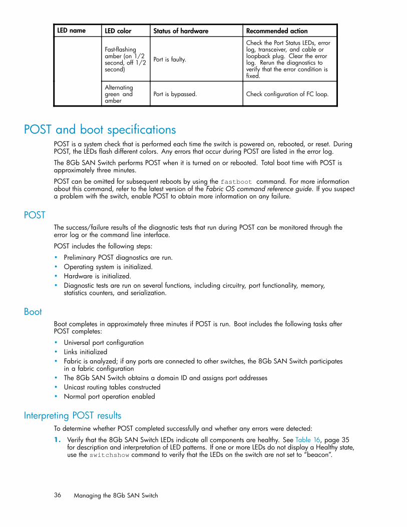
LED name LED color Status of hardware Recommended action
Fast-flashingamber (on 1/2second, off 1/2second)
Port is faulty.
Check the Port Status LEDs, errorlog, transceiver, and cable orloopback plug. Clear the errorlog. Rerun the diagnostics toverify that the error condition isfixed.
Alternatinggreen andamber
Port is bypassed. Check configuration of FC loop.
POST and boot specificationsPOST is a system check that is performed each time the switch is powered on, rebooted, or reset. DuringPOST, the LEDs flash different colors. Any errors that occur during POST are listed in the error log.
The 8Gb SAN Switch performs POST when it is turned on or rebooted. Total boot time with POST isapproximately three minutes.
POST can be omitted for subsequent reboots by using the fastboot command. For more informationabout this command, refer to the latest version of the Fabric OS command reference guide. If you suspecta problem with the switch, enable POST to obtain more information on any failure.
POSTThe success/failure results of the diagnostic tests that run during POST can be monitored through theerror log or the command line interface.
POST includes the following steps:
• Preliminary POST diagnostics are run.• Operating system is initialized.• Hardware is initialized.• Diagnostic tests are run on several functions, including circuitry, port functionality, memory,
statistics counters, and serialization.
BootBoot completes in approximately three minutes if POST is run. Boot includes the following tasks afterPOST completes:
• Universal port configuration• Links initialized• Fabric is analyzed; if any ports are connected to other switches, the 8Gb SAN Switch participates
in a fabric configuration• The 8Gb SAN Switch obtains a domain ID and assigns port addresses• Unicast routing tables constructed• Normal port operation enabled
Interpreting POST resultsTo determine whether POST completed successfully and whether any errors were detected:
1. Verify that the 8Gb SAN Switch LEDs indicate all components are healthy. See Table 16, page 35for description and interpretation of LED patterns. If one or more LEDs do not display a Healthy state,use the switchshow command to verify that the LEDs on the switch are not set to “beacon”.
36 Managing the 8Gb SAN Switch
2. Verify that the 8Gb SAN Switch prompt appears on the terminal of a computer workstationconnected to the switch. If there is no switch prompt when POST completes, press Enter. If the switchprompt still does not appear, try opening another Telnet session or another management tool. If thisis not successful, the 8Gb SAN Switch did not successfully complete POST; contact HP.
3. Review the switch system log for errors. Any errors detected during POST are written to the systemlog, accessible through the errshow command.
For information about all referenced commands and accessing the error log, refer to the latest versionof the HP StorageWorks Fabric OS administrator guide. For information about error messages, referto the Fabric OS system error messages reference manual.
Firmware updateTo achieve best performance, HP recommends running the latest firmware release. Obtain the mostcurrent Fabric OS firmware, configuration files, and MIB files that support this switch from the followingHP website:
http://www.hp.com/go/8gbswitchforbladesystemc-class
To download firmware from the web to another computer (like an FTP server):
NOTE:Web retrieval procedures may be subject to change.
1. Go to the Support section, located on the far right side of the web page. Click Software and Drivers.
2. Locate the Tasks for Brocade 8Gb SAN Switch for HP BladeSystem c-Class section.
3. Click Download drivers and software.
a. Select the applicable switch model.
b. Go to the Select Operating System section. Click Cross operating system (BIOS, Firmware,Diagnostics, etc.)
c. Scroll down to the firmware section of the web page and locate the Firmware table.
d. Locate the latest firmware.
e. Click Download button>> in the last column and follow the prompts in the File Downloaddialog box.
4. To download the code from an FTP server to the switch, connect an Ethernet cable from the FTP serverto the iLO RJ45 on the active OA.
5. Telnet to the switch, and issue firmwaredownload at the command line.
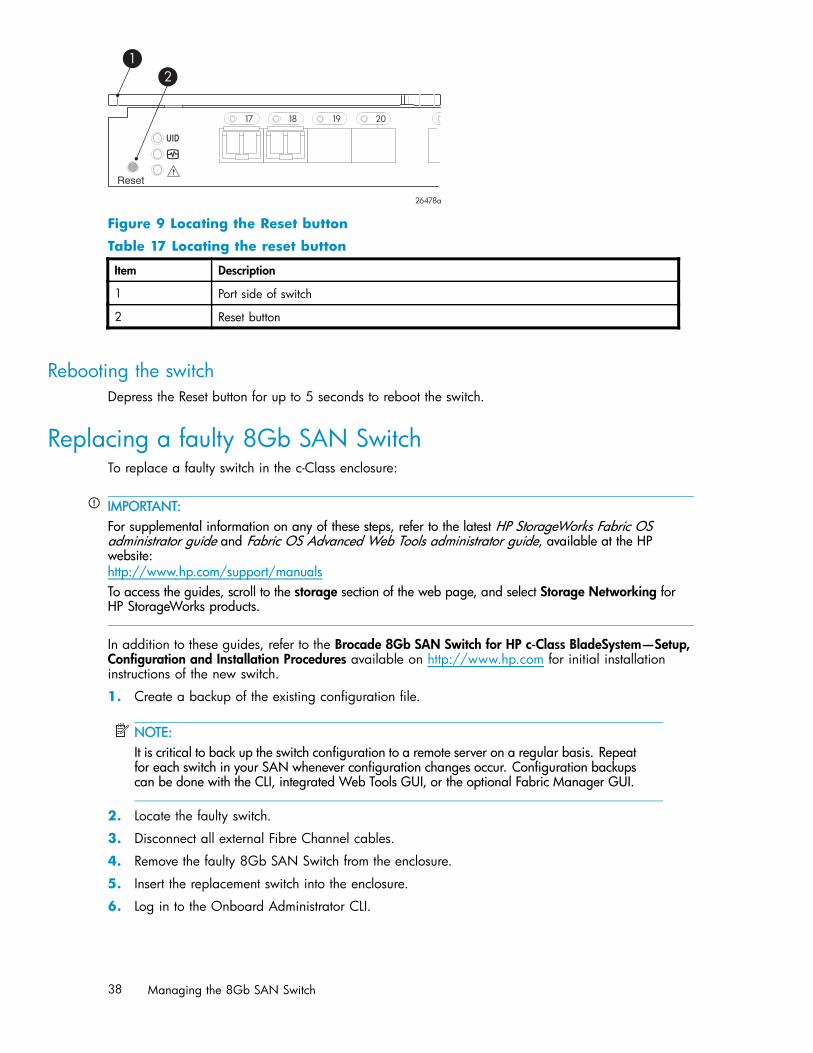
About the reset buttonThe Brocade 8Gb SAN Switch integrates a Reset button, (Figure 9). The Reset button is a small, recessedmicro-switch that is accessed by inserting a pin (or object of similar size) in the small hole.
Use the Reset button to reboot the switch.
Brocade 8Gb SAN Switch for HP BladeSystem c-Class 37
scale: 1" = 1"
17 18 19 20
!
Reset
26478a
21
Figure 9 Locating the Reset button
Table 17 Locating the reset button
Item Description
1 Port side of switch
2 Reset button
Rebooting the switchDepress the Reset button for up to 5 seconds to reboot the switch.
Replacing a faulty 8Gb SAN SwitchTo replace a faulty switch in the c-Class enclosure:
IMPORTANT:For supplemental information on any of these steps, refer to the latest HP StorageWorks Fabric OSadministrator guide and Fabric OS Advanced Web Tools administrator guide, available at the HPwebsite:nl
http://www.hp.com/support/manualsTo access the guides, scroll to the storage section of the web page, and select Storage Networking forHP StorageWorks products.
In addition to these guides, refer to the Brocade 8Gb SAN Switch for HP c‐Class BladeSystem—Setup,Configuration and Installation Procedures available on http://www.hp.com for initial installationinstructions of the new switch.
1. Create a backup of the existing configuration file.
NOTE:It is critical to back up the switch configuration to a remote server on a regular basis. Repeatfor each switch in your SAN whenever configuration changes occur. Configuration backupscan be done with the CLI, integrated Web Tools GUI, or the optional Fabric Manager GUI.
2. Locate the faulty switch.
3. Disconnect all external Fibre Channel cables.
4. Remove the faulty 8Gb SAN Switch from the enclosure.
5. Insert the replacement switch into the enclosure.
6. Log in to the Onboard Administrator CLI.
38 Managing the 8Gb SAN Switch
7. Connect to the switch console, enter:
connect interconnect <bay number>
8. Change the password when prompted by the switch.
9. To restore the configuration, you must disable the switch with the CLI, the integrated Web Tools GUI,or the optional Fabric Manager GUI.
NOTE:If using the CLI, enter switchDisable at the prompt. Refer to the Fabric OS command referenceguide for additional command information.
10. Continue with the switch configuration. Enter the appropriate information when prompted. Makesure that the data entered matches the settings on the faulty switch.
11. Install the same Fabric OS version as the faulty switch using the CLI command firmwareDownload,the integrated Web Tools GUI, or the optional Fabric Manager GUI.
12. Verify that the appropriate licenses are installed on the replacement switch.
13. Save the switch configuration file after making your edits; enter:
configupload
14. Restore the switch configuration from the remote server using the backup configuration file from step 1.
15. Enable the switch. Use the CLI command switchenable, the integrated Web Tools GUI or theoptional Fabric Manager GUI.
16. Connect all external FC cables in the same port locations as before. To connect to the externalswitch ports without connectivity to external devices, the external switch port must be disabled priorto inserting the cable and then re‐enabled after inserting the cable to establish connectivity.
17. Verify that the switch is joined to the fabric and all connected devices log in to the switch; enter:
switchshow
18. Save the configuration file.
IMPORTANT:HP recommends upgrading all switches in the enclosure to the latest available firmware. Checkhttp://www.hp.com for updates.
Brocade 8Gb SAN Switch for HP BladeSystem c-Class 39

40 Managing the 8Gb SAN Switch
A Regulatory compliance andsafety
Regulatory compliance
Federal Communications Commission notice for Class A equipmentThis equipment has been tested and found to comply with the limits for a Class A digital device,pursuant to Part 15 of the FCC Rules. These limits are designed to provide reasonable protection againstharmful interference when the equipment is operated in a commercial environment. This equipmentgenerates, uses and can radiate radio frequency energy and, if not installed and used in accordancewith the instruction manual, may cause harmful interference to radio communications. Operation of thisequipment in a residential area is likely to cause harmful interference, in which case the user will berequired to correct the interference at his own expense. The end user of this product should be awarethat any changes or modifications made to this equipment without the approval of Hewlett-Packardcould result in the product not meeting the Class A limits, in which case the FCC could void the user'sauthority to operate the equipment.
ModificationsThe FCC requires the user to be notified that any changes or modifications made to this device that are notexpressly approved by Hewlett-Packard Company my void the user's authority to operate the equipment.
CablesConnections to this device must be made with shielded cables with metallic RFI/EMI connector hoodsin order to maintain compliance with FCC Rules and Regulations.
Regulatory compliance identification numbersFor the purpose of regulatory compliance certifications and identification, your product has beenassigned a unique Regulatory Model Number. The RMN can be found on the product nameplate label,along with all required approval markings and information. When requesting compliance information forthis product, always refer to this RMN. The Regulatory Model Number should not be confused with themarketing name or model number of the product.
Laser device complianceThe fiber optic transceiver contains a laser that is classified as a “Class 1 Laser Product” in accordancewith US FDA regulations and the IEC 60825-1. The product does not emit hazardous laser radiation.
This laser product complies with 21 CFR 1040.10 and 1040.11 except for editions pursuant to LaserNotice No. 50, dated May 27, 2001; and with IEC 60825-1:1993/A2:2001.
Brocade 8Gb SAN Switch for HP BladeSystem c-Class 41

WARNING!Use of controls or adjustments or performance of procedures other than those specified herein or inthe laser product’s installation guide may result in hazardous radiation exposure. To reduce the riskof exposure to hazardous radiation:• Do not try to open the laser device enclosure. There are no user-serviceable components inside.• Do not operate controls, make adjustments, or perform procedures to the laser device other than
those specified herein.• Allow only HP authorized service technicians to repair the laser device.
Certification and classification informationThis product contains a laser internal to the fiber optic (FO) transceiver for connection to the FibreChannel communications port.
In the USA, the FO transceiver is certified as a Class 1 laser product conforming to the requirementscontained in the Department of Health and Human Services (DHHS) regulation 21 CFR, Subchapter J. Alabel on the plastic FO transceiver housing indicates the certification.
Outside the USA, the FO transceiver is certified as a Class 1 laser product conforming to the requirementscontained in IEC 825–1:1993 and EN 60825–1:1994, including Amendment 11:1996 and Amendment2:2001.
Laser product labelThe optional label in Figure 10 or equivalent may be located on the surface of the HP supplied laserdevice.
Figure 10 Class 1 laser product label
This optional label indicates that the product is classified as a CLASS 1 LASER PRODUCT. This label mayappear on the laser device installed in your product.
International notices and statements
Canadian notice (avis Canadien)
Class A equipmentThis Class A Digital apparatus meets all requirements of the Canadian Interference-Causing EquipmentRegulations.
Cet appareil numérique de la classe A respecte toutes les exigences du Règlement sur le matérielbrouilleur du Canada.
42 Regulatory compliance and safety

European union regulatory notice
BSMI notice
Japanese notice
Brocade 8Gb SAN Switch for HP BladeSystem c-Class 43

Korean notice
Safety
Battery replacement noticeYour switch is equipped with a lithium manganese dioxide, a vanadium pentoxide, or an alkaline internalbattery or battery pack. There is a danger of explosion and risk of personal injury if the battery isincorrectly replaced or mistreated. Replacement is to be done by an HP authorized service provider usingthe HP spare part designated for this product. For more information about battery replacement or properdisposal, contact an HP authorized service provider.
WARNING!Your switch contains an internal lithium manganese dioxide, a vanadium pentoxide, or an alkalinebattery pack. There is risk of fire and burns if the battery pack is not properly handled. To reduce therisk of personal injury:• Do not attempt to recharge the battery.• Do not expose to temperatures higher than 60 ºC.• Do not disassemble, crush, puncture, short external contacts, or dispose of in fire or water.• Replace only with the HP spare part designated for this product.
Batteries, battery packs, and accumulators should not be disposed of together with the general householdwaste. To forward them to recycling or proper disposal, please use the public collection system or returnthem to HP, an authorized HP Partner, or their agents.
For more information about battery replacement or proper disposal, contact an HP authorized reseller orservice provider.
Taiwan battery recycling notice
The Taiwan EPA requires dry battery manufacturing or importing firms in accordance with Article 15of the Waste Disposal Act to indicate the recovery marks on the batteries used in sales, giveaway, orpromotion. Contact a qualified Taiwanese recycler for proper battery disposal.
44 Regulatory compliance and safety

Power cordsThe power cord set must meet the requirements for use in the country where the product was purchased.If the product is to be used in another country, purchase a power cord that is approved for use inthat country.
The power cord must be rated for the product and for the voltage and current marked on the productelectrical ratings label. The voltage and current rating of the cord should be greater than the voltage andcurrent rating marked on the product. In addition, the diameter of the wire must be a minimum of 1.00mm2 or 18 AWG, and the length of the cord must be between 1.8 m (6 ft) and 3.6 m (12 ft). If you havequestions about the type of power cord to use, contact an HP authorized service provider.
NOTE:Route power cords so that they will not be walked on and cannot be pinched by items placed uponor against them. Pay particular attention to the plug, electrical outlet, and the point where the cordsexit from the product.
Japanese power cord statement
Brocade 8Gb SAN Switch for HP BladeSystem c-Class 45

46 Regulatory compliance and safety
B Electrostatic discharge
This appendix provides the following information:
• How to prevent electrostatic discharge, page 47• Grounding methods, page 47
How to prevent electrostatic dischargeTo prevent damage to the system, you must follow certain precautions when setting up the system orhandling parts. A discharge of static electricity from a finger or other conductor may damage systemboards or other static-sensitive devices. This type of damage may reduce the life expectancy of the device.
To prevent electrostatic damage, observe the following precautions:
• Avoid hand contact by transporting and storing products in static-safe containers.• Keep electrostatic-sensitive parts in their containers until they arrive at static-free workstations.• Place parts on a grounded surface before removing them from their containers.• Avoid touching pins, leads, or circuitry.• Always make sure you are properly grounded when touching a static-sensitive component or
assembly.
Grounding methodsThere are several methods for grounding. Use one or more of the following methods when handling orinstalling electrostatic-sensitive parts:
• Use a wrist strap connected by a ground cord to a grounded workstation or chassis. Wrist strapsare flexible straps with a minimum of 1 megohm ± 10 percent resistance in the ground cords. Toprovide proper ground, wear the strap snug against the skin.
• Use heel straps, toe straps, or boot straps at standing workstations. Wear the straps on both feetwhen standing on conductive floors or static-dissipating floor mats.
• Use conductive field service tools.• Use a portable field service kit with a folding static-dissipating work mat.
If you do not have any of the suggested equipment for proper grounding, have an HP authorizedreseller install the part.
NOTE:For more information on static electricity, or for assistance with product installation, contact yourHP authorized reseller.
Brocade 8Gb SAN Switch for HP BladeSystem c-Class 47

48 Electrostatic discharge
C SAN Switch technicalspecifications
This appendix provides the following information:
• General specifications, page 49• Weight and physical dimensions, page 50• Environmental requirements, page 50• Supported SFPs, page 51• Supported HBAs, page 51
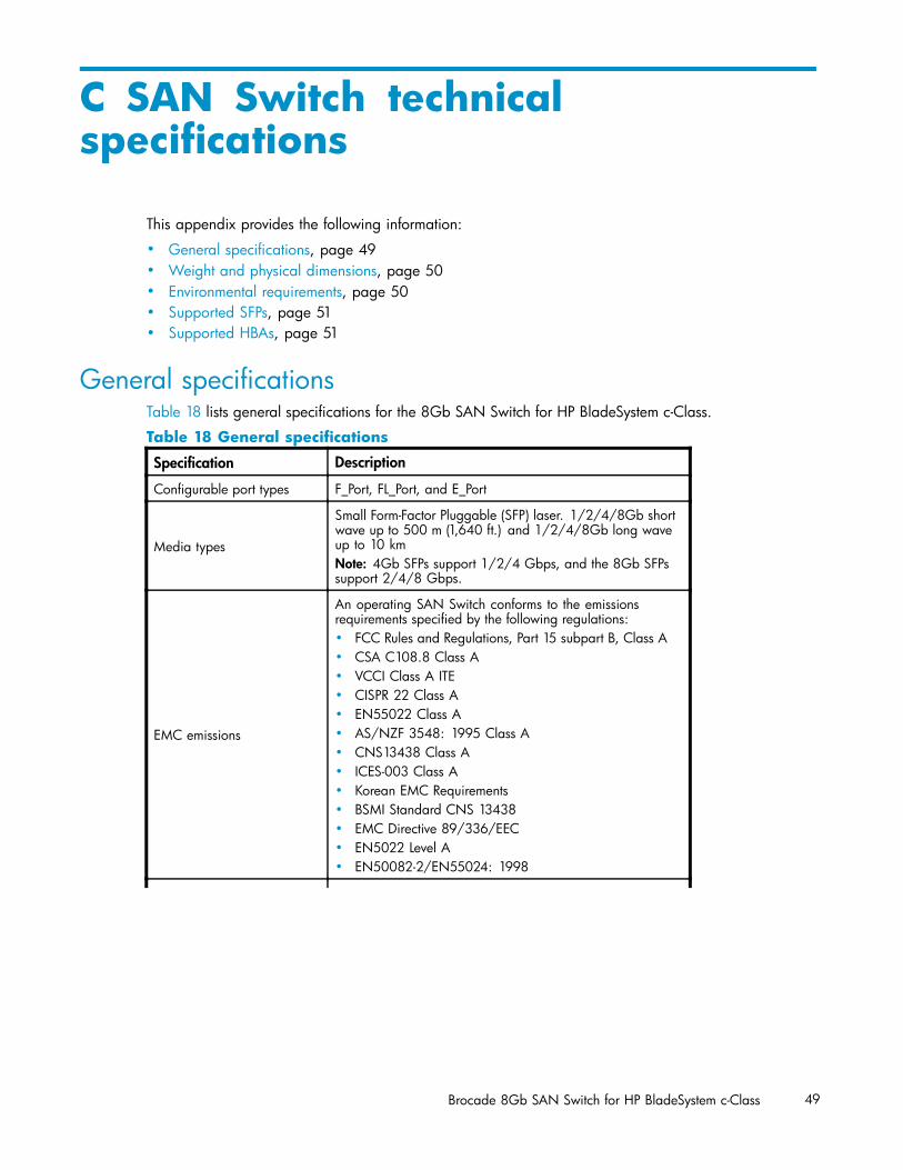
General specificationsTable 18 lists general specifications for the 8Gb SAN Switch for HP BladeSystem c-Class.
Table 18 General specifications
Specification Description
Configurable port types F_Port, FL_Port, and E_Port
Media types
Small Form-Factor Pluggable (SFP) laser. 1/2/4/8Gb shortwave up to 500 m (1,640 ft.) and 1/2/4/8Gb long waveup to 10 kmNote: 4Gb SFPs support 1/2/4 Gbps, and the 8Gb SFPssupport 2/4/8 Gbps.
EMC emissions
An operating SAN Switch conforms to the emissionsrequirements specified by the following regulations:• FCC Rules and Regulations, Part 15 subpart B, Class A• CSA C108.8 Class A• VCCI Class A ITE• CISPR 22 Class A• EN55022 Class A• AS/NZF 3548: 1995 Class A• CNS13438 Class A• ICES-003 Class A• Korean EMC Requirements• BSMI Standard CNS 13438• EMC Directive 89/336/EEC• EN5022 Level A• EN50082-2/EN55024: 1998
Brocade 8Gb SAN Switch for HP BladeSystem c-Class 49

Specification Description
EMC immunity
• IEC 61000-4-2 Severity Level 3 for Electrostatic Discharge• IEC 61000-4-3 Severity Level 3 for Radiated Fields• IEC 61000-4-4 Severity Level 3 for Fast Transients• IEC 61000-4-5 Severity Level 3 for Surge Voltage• IEC 61000-4-6 Conducted Emissions• IEC 61000-4-11 Voltage Variations• EN 61000-4-12 Oscillatory Waves Immunity• EN 61000-3-2 Limits for Harmonic Current Emissions• EN 61000-3-3 JEIDA
System architecture Nonblocking shared-memory switch
ANSI protocol FC-PH (FC Physical and Signalling Interface standard)
Modes of operation FC Class 2, Class 3, and Class F
Maximum frame size 2112-byte
Port-to-port latency Less than 2 microseconds with no contention (destinationport is free)
Weight and physical dimensionsnl
Table 19 lists physical properties.
Table 19 8Gb SAN Switch physical dimensions
Dimension Measurement
Height 29.3 mm (1.15 in)
Width 208 mm (8.19 in)
Depth 280 mm (11.02 in)
Weight 1.27 kg (2.8 lb)
Environmental requirementsTo ensure proper operation, the switch must not be subjected to environmental conditions beyond thosefor which it was tested. The ranges specified in Table 20 list the acceptable environment for bothoperating and nonoperating conditions.
Table 20 Environmental requirements
Condition Acceptable range during operation Acceptable range duringnon-operation
Ambienttemperature
104°F/40 °C at sea level, derated 1 Cper 1000 ft above sea level
-40°C to 70°C with maximum rate ofchange of 20 C /hr
Humidity 5% to 90% relative humidity,non-condensing
50% to 80% relative humidity,non-condensing
Altitude 0 to 10,000 ft (3 km) above sea level 0 to 40,000 ft (12 km) above sea level
Shock 40 G, 2mS duration 140 G, 2mS,
Vibration 0.5 G, 10–500 Hz 2.0 G, 5–500 Hz
Airflow 47 cubic ft/minute None required
50 SAN Switch technical specifications
Supported SFPsDo not use unsupported SFPs. They may not fit correctly and may void your warranty. Any port with anunsupported SFP will automatically be disabled by switch firmware, leaving the port non-operational. SeeSupported SFP transceiver options, page 17 for a list of supported SFPs.
For a complete list of supported devices, refer to the latest version of the HP StorageWorks SAN designreference guide at the HP website:nl
http://h18000.www1.hp.com/products/storageworks/san/documentation.html.
Supported HBAsFor a list of HBAs that have been tested and are known to work with the SAN switches, refer to the latestversion of the HP StorageWorks SAN design reference guide at the HP website:nl
http://h18000.www1.hp.com/products/storageworks/san/documentation.html.
Brocade 8Gb SAN Switch for HP BladeSystem c-Class 51

52 SAN Switch technical specifications
Glossary
This glossary defines terms used in this guide or related to this product. It is not a comprehensiveglossary of computer terms.
AL_PA Arbitrated loop physical address. A unique 8-bit value assigned during loopinitialization to a port in an arbitrated loop. See also ???.
alias server A fabric software facility that supports multicast group management.
API Application programming interface. A defined protocol that allows applicationsto interface with a set of services.
arbitrated loop A shared 100 Mb/s Fibre Channel transport structured as a loop. Supports upto 126 devices and one fabric attachment. See also ???, ???.
AW_TOV Arbitration wait time-out value. The minimum time an arbitrating L_Port waitsfor a response before beginning loop initialization.
backup FCS switch Backup fabric configuration server switch. The switch or switches assigned asbackup in case the primary FCS switch fails.
bandwidth The total transmission capacity of a cable, link, or system. Usually measured inbits per second (b/s). May also refer to the range of transmission frequenciesavailable to a link or system.
broadcast The transmission of data from a single source to all devices in the fabric,regardless of zoning.
buffer-to-bufferflow control
Management of the frame transmission rate in either a point-to-point topology oran arbitrated loop. See also ???, ???, ???.
CLI Command line interface. Interface that depends entirely on the use ofcommands, such as through Telnet or SNMP, and does not involve a GUI.
compact flash Flash (temporary) memory that is used in a manner similar to hard disk storage.It is connected to a bridging component that connects to the PCI bus of theprocessor. Not visible within the processor's memory space.
configuration The way a system is set up. May refer to hardware or software:• Hardware: The number, type, and arrangement of components that make up
a system or network.• Software: The set of parameters that guide switch operation. May include
general system parameters, IP address information, domain ID, and otherinformation. Modifiable by any login with administrative privileges. Mayalso refer to a set of zones.
CRC Cyclic redundancy check. A check for transmission errors that is includedin every data frame.
data word A type of transmission word that occurs within frames. The frame header, datafield, and CRC all consist of data words.
defined zoneconfiguration
The set of all zone objects defined in the fabric. May include multiple zoneconfigurations. See also ???, ???.
directory service See ???.
Brocade 8Gb SAN Switch for HP BladeSystem c-Class 53

DLS Dynamic load sharing. Dynamic distribution of traffic over available paths.Allows for recomputing of routes when an Fx_Port or E_Port changes status.
domain ID Unique identifier used in routing frames for all switches in a fabric. Usuallyassigned by the principal switch, but can be assigned manually. The domain IDfor an HP switch can be any integer between 1 and 239. The default domain IDis usually 1.
E_D_TOV Error-detect time-out value. The minimum time a target waits for a sequence tocomplete before initiating recovery. Can also be defined as the maximum timeallowed for a round-trip transmission before an error condition is declared.
E_Port Expansion port. A type of switch port that can be connected to an E_Port onanother switch to create an ISL. See also ???, ???.
EE_Credit End-to-end credit. The number of receive buffers allocated by a recipient portto an originating port. Used by Class 1 and Class 2 services to manage theexchange of frames across the fabric between source and destination.
EIA rack A storage rack that meets the standards set by the Electronics IndustryAssociation (EIA).
enabled zoneconfiguration
The currently enabled configuration of zones. Only one configuration can beenabled at a time. See also ???, ???.
end-to-end flowcontrol
A facility that governs flow of class 1 and class 2 frames between N_Ports.
error With respect to FC, a missing or corrupted frame, time-out, loss ofsynchronization, or loss of signal (link error).
exchange The highest-level FC mechanism used for communication between N_Ports.Composed of one or more related sequences; can work in one or bothdirections.
F_Port Fabric port. A port that is able to transmit under fabric protocol and interfaceover links. Can be used to connect an N_Port to a switch. See also ???.
fabric An FC network containing two or more switches in addition to hosts anddevices. May also be called a switched fabric.
fabric name The unique identifier assigned to a fabric and communicated during login andport discovery.
FCIA Fibre Channel Industry Association. An international organization of FC industryprofessionals. Among other things, provides oversight of ANSI and industrystandards.
FCP Fibre Channel Protocol. Mapping of protocols onto the FC standard protocols.For example, SCSI FCP maps SCSI-3 onto FC.
FCS switch Fabric Configuration Server switch. One or more designated HP switches thatstore and manage the configuration and security parameters for all switchesin the fabric.
Fibre Channel The primary protocol for building SANs to transmit data between servers,switches, and storage devices. Unlike IP and Ethernet, Fibre Channel isdesigned to support the needs of storage devices of all types. It is a high-speed,serial, bidirectional, topology-independent protocol, and is a highly scalableinterconnection between computers, peripherals, and networks.
fill word An IDLE or ARB ordered set that is transmitted during breaks between dataframes to keep the link active.
54 Glossary

FLOGI The process by which an N_Port determines whether a fabric is present and, ifso, exchanges service parameters with it. See also ???.
FL_Port Fabric loop port. A port that is able to transmit under fabric protocol and hasarbitrated loop capabilities. Can also be used to connect an NL_Port to aswitch. See also ???.
frame The Fibre Channel structure used to transmit data between ports. Consistsof a start-of-frame delimiter, header, optional headers, data payload, cyclicredundancy check, and end-of-frame delimiter. There are two types of frames:link control frames and data frames. See also ???.
FRU Field-replaceable unit. A component that can be replaced on site.
FS Fibre Channel Service. A service that is defined by FC standards and exists at awell-known address. The Simple Name Server, for example, is an FC service.
FSP Fibre Channel Service Protocol. The common protocol for all fabric services; it istransparent to the fabric type or topology.
FSPF Fabric shortest path first. HP routing protocol for FC switches.
Fx_Port A fabric port that can operate as an F_Port or FL_Port.
G_Port Generic port. A port that can operate as an E_Port or F_Port. A port is definedas a G_Port when it is not yet connected or has not yet assumed a specificfunction in the fabric. See also ???, ???, ???.
hard address The AL_PA that an NL_Port attempts to acquire during loop initialization. Seealso ???.
idle Continuous transmission of an ordered set over an FC link when no data isbeing transmitted, to keep the link active and maintain bit, byte, and wordsynchronization.
integrated fabric The fabric created by connecting multiple HP switches with multiple ISL cables,and configuring the switches to handle traffic as a seamless group.
ISL trunking The distribution of traffic over the combined bandwidth of multiple ISLs. A setof trunked ISLs is called a trunking group; the ports in a trunking group arecalled trunking ports.
isolated E_Port An E_Port that is online but not operational due to overlapping domain IDs ornonidentical parameters (such as E_D_TOVs). See also ???.
K28.5 A special 10-bit character that indicates the beginning of a transmission wordthat performs FC control and signaling functions. The first seven bits are thecommon pattern.
kernel flash Flash (temporary) memory connected to the peripheral bus of the processor andvisible within the processor's memory space. Also called a user flash.
L_Port Loop port. A node port (NL_Port) or fabric port (FL_Port) that has arbitrated loopcapabilities. An L_Port can be in one of two modes:• Fabric mode: Connected to a port that is not loop capable and is using
fabric protocol.• Loop mode: In an arbitrated loop and using loop protocol. An L_Port in loop
mode can also be in participating mode or non-participating mode.See also ???.
Brocade 8Gb SAN Switch for HP BladeSystem c-Class 55

latency The time required to transmit a frame from the time it is sent until it arrives.Together, latency and bandwidth define the speed and capacity of a link orsystem.
link With respect to FC, a physical connection between two ports, consisting ofboth transmit and receive fibers.
link services A protocol for link-related actions.
LIP Loop initialization primitive. The signal that begins initialization in a loop. Itindicates either loop failure or the resetting of a node.
LM_TOV Loop master time-out value. The minimum time that the loop master waits for aloop initialization sequence to return.
loop failure Loss of signal within a loop for any period of time; loss of synchronization forlonger than the time-out value.
Loop_ID A hexadecimal value representing one of the 127 possible AL_PA values in anarbitrated loop. See also ???.
loop initialization The logical procedure used by an L_Port to discover its environment. Can beused to assign AL_PA addresses, detect loop failure, or reset a node. See also???.
LPSM Loop port state machine. The logical entity that performs arbitrated loopprotocols and defines the behavior of L_Ports when they require access to anarbitrated loop. See also ???.
LWL Long wavelength. A type of fiber optic cabling that is based on 1300 mmlasers and supports link speeds up to 2 Gb/s. May also refer to the type oftransceiver. See also ???.
master port The port that determines the routing paths for all traffic flowing through atrunking group. One of the ports in the first ISL in the trunking group isdesignated as the master port for that group. See also ???.
MIB Management Information Base. An SNMP structure to help with devicemanagement, providing configuration and device information. See also ???.
multicast The transmission of data from a single source to multiple specified N_Ports (asopposed to all ports on the network).
N_Port Node port. A port on a node that can connect to an FC port or to anotherN_Port in a point-to-point connection.
name server A term frequently used to indicate a Simple Name Server (SNS). See also ???.
NL_Port Node loop port. A node port that has arbitrated loop capabilities. Used toconnect an equipment port to the fabric in a loop configuration through anFL_Port. See also ???.
node An FC device that contains an N_Port or NL_Port.
non-participatingmode
A mode in which an L_Port in a loop is inactive and cannot arbitrate or sendframes, but can retransmit any received transmissions. This mode is entered ifthere are more than 127 devices in a loop and an AL_PA cannot be acquired.See also ???, ???.
Nx_Port A node port that can operate as an N_Port or NL_Port.
OnboardAdministrator(OA)
The HP BladeSystem Onboard Administrator (OA) is the enclosure managementprocessor, subsystem, and firmware base used to support the HP BladeSystemc7000 or HP BladeSystem c3000 and all the managed devices containedwithin the enclosure.
56 Glossary

packet A set of information transmitted across a network.
participatingmode
A mode in which an L_Port in a loop has a valid AL_PA and can arbitrate, sendframes, and retransmit received transmissions.
path selection The selection of a transmission path through the fabric. HP switches use the FSPFprotocol for transmission path selection.
phantom address An AL_PA value assigned to a device that is not physically in the loop. Alsoknown as phantom AL_PA. See also ???, ???.
phantom device A device that is not physically in an arbitrated loop but is logically includedthrough the use of a phantom address. See also ???.
PLOGI Port login. The port-to-port login process by which initiators establish sessionswith targets. See also ???.
point-to-point An FC topology that employs direct links between each pair of communicatingentities. See also ???.
port cage The metal casing extending out of the FC port on the switch and into which aGBIC or SFP transceiver can be inserted.
Port_Name The unique identifier assigned to an FC port. It is communicated during loginand port discovery.
POST Power-on self-test. A series of diagnostic tests run by a switch after it is poweredon.
primary FCSswitch
Primary Fabric Configuration Server switch. The switch that actively managesthe configuration and security parameters for all switches in the fabric.
private loop An arbitrated loop that does not include a participating FL_Port.
private NL_Port An NL_Port that communicates only with other private NL_Ports in the sameloop and does not log in to the fabric.
public device A device that supports arbitrated loop protocol, can interpret 8-bit addresses,and can log in to the fabric. See also ???.
public loop An arbitrated loop that includes a participating FL_Port and may contain bothpublic and private NL_Ports. See also ???.
public NL_Port An NL_Port that logs in to the fabric, can function within a public or privateloop, and can communicate with private or public NL_Ports. See also ???.
quad A group of four adjacent ports that share a common pool of frame buffers.
R_A_TOV Resource allocation time-out value. The maximum time a frame can be delayedin the fabric and still be delivered.
RAID Redundant Array of Independent Disks. A collection of disk drives that appearas a single volume to the server and are fault tolerant through mirroring orparity checking.
request rate The rate at which requests arrive at a servicing entity.
route With respect to a fabric, the communication path between two switches. Mayalso apply to the specific path taken by an individual frame from source todestination.
routing The assignment of frames to specific switch ports according to frame destination.
RR_TOV Resource recovery time-out value. The minimum time a target device in a loopwaits after a LIP before logging out a SCSI initiator.
Brocade 8Gb SAN Switch for HP BladeSystem c-Class 57

RSCN Registered state change notification. A switch function that allows notification offabric changes to be sent from the switch to the specified nodes.
SAN Storage area network. A network of systems and storage devices thatcommunicate using FC protocols.
SDRAM Synchronous dynamic random access memory. The main memory for a switch.See also ???.
sequence A group of related frames transmitted in the same direction between twoN_ports.
service rate The rate at which an entity can service requests.
single mode The fiber optic cabling standard that corresponds to distances up to 10 kmbetween devices.
SNMP Simple Network Management Protocol. An Internet management protocol thatuses either IP for network-level functions and UDP for transport functions, orTCP/IP for both. SNMP can be made available over other protocols (such asUDP/IP) because it does not rely on the underlying communication protocols.See also ???, ???.
SNS Simple Name Server. A switch service that stores names, addresses, andattributes for up to 15 minutes, and provides them as required to other devices inthe fabric. May also be referred to as a directory service.
switch Hardware that routes frames according to FC protocol and is controlled bysoftware.
switch port A port on a switch. Switch ports can be E_Ports, F_Ports, or FL_Ports.
SWL short-wavelength. A type of fiber optic cabling that is based on 850 mm lasersand supports link speeds up to 2 Gb/s. May also refer to the type of transceiver.
tenancy The time span that begins when a port wins arbitration in a loop and ends whenthe same port returns to the monitoring state. Also called loop tenancy.
throughput The rate of data flow achieved within a cable, link, or system. Usually measuredin bits per second (b/s).
topology With respect to FC, the configuration of the FC network and the resultingcommunication paths allowed. There are three possible topologies:• Point-to-point: A direct link between two communication ports• Switched fabric: Multiple N_Ports linked to a switch by F_Ports• Arbitrated loop: Multiple NL_Ports connected in a loop
transmissioncharacter
A 10-bit character encoded according to the rules of the 8b/10b algorithm.
transmission word A group of transmission characters.
trap (SNMP) The message sent by an SNMP agent to inform the SNMP management stationof a critical error. See also ???.
U_Port Universal port. A switch port that can operate as a G_Port, E_Port, F_Port, orFL_Port. A port is defined as a U_Port when it is not connected or has not yetassumed a specific function in the fabric. See also ???, ???, ???.
well-knownaddress
With respect to FC, a logical address defined by the FC standards as assignedto a specific function and stored on the switch.
58 Glossary
workstation A computer used to access and manage the fabric. May also be called amanagement station or host.
WWN World wide name. An identifier that is unique worldwide. Each entity in afabric has a distinct WWN.
zone A set of devices and hosts attached to the same fabric and configured asbeing in the same zone. Devices and hosts within the same zone have accesspermission to others in the zone, but are not visible to any outside the zone.See also ???, ???.
zone configuration A specified set of zones. Enabling a configuration enables all zones in thatconfiguration. See also ???, ???.
Brocade 8Gb SAN Switch for HP BladeSystem c-Class 59

60 Glossary
Index
Aadvanced web tools, 31advanced zoning, 16audience, 9
Bboot, 36boot specifications, 36
Ccommand line interface, 31conventions
document, 10text symbols, 10
Ddiagnostics, 33document
conventions, 10related documentation, 9, 9
documentationproviding feedback, 11
EEIA, 20environmental requirements, 50Ethernet connection, 25
Ffabric license
base, 15full, 15Power Pack, 15
fabric licenses, 15Fibre Channel
FC domain ID, 27
Ggeneral specifications, 49grounding methods, 47
HHBAs, supported, 51help
obtaining, 9
HPstorage website, 11Subscriber's choice website, 11technical support, 9
IIP address, 20, 25ISL
trunking groups, 16
LLED
interpreting activity, 34location, 34patterns, 34
LED patterns, 35licenseshow, 26long wavelength, see LWL, 13
Mmanagement station, 32
Pport
configurable types, 13speed, 13
port LED patterns, 35POST, 36POST results, 36POST specifications, 36Power Pack, 15
Rrelated documentation, 9, 9
SSAN Switch
configuration, 25installing, 20licensing, 15maintenance, 32management features, 31port diagram, 14power, 33
SFP transceiver, 25removing, 32
Brocade 8Gb SAN Switch for HP BladeSystem c-Class 61

SFP transceiverssupported, 51
shipping carton contents, 19SNMP applications, 31specifications
environmental requirements, 50general, 49physical, 50
Subscriber's choice, HP, 11supported HBAs, 51supported sfp options, 17supported SFPs, 51symbols in text, 10
Ttechnical support
HP, 9text symbols, 10transceiver, 13, 14, 25, 33, 35, 36
Wweb tools, 16websites
HP documentation, 11HP storage, 11HP Subscriber's choice, 11
62


![[TEST OPOSICIONES] Constitucion Española (5697 preguntas)](https://img.dokumen.tips/doc/110x75/5571f28a49795947648cb19a/test-oposiciones-constitucion-espanola-5697-preguntas.jpg)