Embed Size (px)
Citation preview
Brocade 7810 IP Extension Switch Deployment User Guide
28 February 2019
7810-IPEX-UG10028 February 2019

Copyright © 2019 Broadcom. All Rights Reserved. Broadcom, the pulse logo, Brocade, and the stylized B logo are amongthe trademarks of Broadcom in the United States, the EU, and/or other countries. The term “Broadcom” refers toBroadcom Inc. and/or its subsidiaries.
Broadcom reserves the right to make changes without further notice to any products or data herein to improve reliability,function, or design. Information furnished by Broadcom is believed to be accurate and reliable. However, Broadcom doesnot assume any liability arising out of the application or use of this information, nor the application or use of any product orcircuit described herein, neither does it convey any license under its patent rights nor the rights of others.
The product described by this document may contain open source software covered by the GNU General Public Licenseor other open source license agreements. To find out which open source software is included in Broadcom products, viewthe licensing terms applicable to the open source software, and obtain a copy of the programming source code, pleasevisit https://www.broadcom.com/.

Table of Contents
Chapter 1: Introduction........................................................................................................................51.1 About This Document................................................................................................................................................ 51.2 What Is New in This Document................................................................................................................................. 51.3 Supported Hardware and Software...........................................................................................................................51.4 Contacting Technical Support for Your Brocade® Product....................................................................................51.5 Document Feedback.................................................................................................................................................. 5
Chapter 2: Steps to Configure IP Extension......................................................................................7Chapter 3: Reference Architecture.................................................................................................... 8Chapter 4: Assumptions and Prerequisites Specific to This Configuration................................ 10Chapter 5: Configuring Brocade 7810 IP Extension....................................................................... 12Chapter 6: Validating Brocade 7810 IP Extension...........................................................................20Chapter 7: Validating the Network with a Traffic Generator...........................................................32Chapter 8: Where to Learn More.......................................................................................................36Chapter 9: Revision History.............................................................................................................. 38
7810-IPEX-UG100 Brocade 7810 IP Extension Switch Deployment User Guide
7810-IPEX-UG1003

7810-IPEX-UG100 Brocade 7810 IP Extension Switch Deployment User Guide
7810-IPEX-UG1004

Introduction
1.1 About This DocumentThis document describes the steps required to configure the Brocade 7810 Extension Switch for Fabric OS® IP Extension.
1.2 What Is New in This DocumentThis is the first release of this document.
1.3 Supported Hardware and SoftwareThis guide is devoted to the Brocade 7810 Extension Switch.
The supported software is Brocade FOS 8.2.1x.
1.4 Contacting Technical Support for Your Brocade® ProductFor product support information and the latest information on contacting the Technical Assistance Center, go to https://www.broadcom.com/support/fibre-channel-networking/. If you have purchased Brocade® product support directly fromBroadcom, use one of the following methods to contact the Technical Assistance Center 24x7.
Online Telephone
For nonurgent issues, the preferred method is to log in tomyBroadcom at https://www.broadcom.com/mybroadcom. (Youmust initially register to gain access to the Customer SupportPortal.) Once there, select Customer Support Portal > SupportPortal. You will now be able to navigate to the following sites:n Knowledge Search: Clicking the top-right magnifying glass
brings up a search bar.n Case Management: The legacy MyBrocade case
management tool (MyCases) has been replaced with the FibreChannel Networking case management tool.
n DocSafe: You can download software and documentation.n Other Resources: Licensing Portal (top), SAN Health (top and
bottom), Communities (top), Education (top).
Required for Severity 1 (critical) issues:Please call Fibre Channel Networking Global Support at one of thenumbers listed at https://www.broadcom.com/support/fibre-channel-networking/.
If you purchased Brocade product support from a Broadcom OEM/solution provider, contact your OEM/solution providerfor all your product support needs.
n OEM/solution providers are trained and certified by Broadcom to support Brocade products.n Broadcom provides backline support for issues that cannot be resolved by the OEM/solution provider.n Brocade Supplemental Support augments your existing OEM support contract, providing direct access to Brocade
expertise. For more information on this option, contact Broadcom or your OEM.n For questions regarding service levels and response times, contact your OEM/solution provider.
1.5 Document FeedbackQuality is our first concern. We have made every effort to ensure the accuracy and completeness of this document.However, if you find an error or an omission or if you think that a topic needs further development, we want to hear from
7810-IPEX-UG100 Brocade 7810 IP Extension Switch Deployment User Guide
7810-IPEX-UG1005

you. Send your feedback to [email protected]. Provide the publication title, publication number, topicheading, page number, and as much detail as possible.
7810-IPEX-UG100 Brocade 7810 IP Extension Switch Deployment User Guide
7810-IPEX-UG1006

Steps to Configure IP Extension
This document is an adjunct to the Brocade Fabric OS Extension User Guide, version 8.2.1x or later, and the BrocadeFabric OS Command Reference Manual, version 8.2.1 or later.
The details in this document are specific to the configuration of IP Extension on the Brocade 7810 Extension Switch(image below). Configuration of the Brocade 7840 Extension Switch and the SX6 Extension Blade may vary. Refer to theBrocade Fabric OS Extension User Guide, version 8.2.1x, for details on configuring those platforms.
Figure 1: Brocade 7810 Extension Switch
The steps to configure Brocade IP Extension include the following. Although each step is important, none arecomplicated.
1. Establish the extension architecture.2. Gather the necessary information to configure your architecture (for example, the Brocade 7810 management address
and whether the Brocade 7810 Switch is a base or full-license).3. Configure each Brocade 7810 Switch.4. Validate each Brocade 7810 Switch.5. Redirect end-device IP storage traffic to the appropriate IP Extension gateway.6. Validate the IP storage traffic across IP Extension.
7810-IPEX-UG100 Brocade 7810 IP Extension Switch Deployment User Guide
7810-IPEX-UG1007

Reference Architecture
For the following discussion, refer to the architecture and data flow diagrams below.
Referenced throughout this document is a 1x1 architecture where one Brocade 7810 Switch is located at each location.There are two locations: local and remote.
NOTEYou may have chosen a different extension environment. For example, you may have chosen to use twoBrocade 7810 Switches at each location instead of one.
n Local refers to the location where data originates, and remote refers to the location where data is replicated.n Each Brocade 7810 Switch has three distinct “sides”: LAN, WAN, and FC, where each side has unique configuration
requirements.n Each WAN link carries one circuit and represents a distinct path ("A" or "B") starting from the data center (DC) WAN
switches.n BET (Brocade Extension Trunking) refers to the use of multiple circuits (two in this case) comprising a single tunnel
(represented by a VE_Port). The member circuits aggregate into the overall bandwidth of the tunnel, take diversepaths for greater availability, enable failover/failback, and never lose or deliver out-of-order data. This means that thetunnel passes through both the top and bottom WAN links. Two or more circuits are a best practice and are stronglyrecommended.
n Each location has two DC LAN switches. They are interconnected to each other forming a single logical switch(referred to as a vPC [Virtual Port Channel], VSS [vNetwork Standard Switch], or vLAG [Virtual Link AggregationGroup]). Only a single connection is allowed: a single physical connection or multiple connections forming one logicalconnection. Link aggregation (LAG) is a method of using multiple links for redundancy while maintaining a singlelogical connection. This reference architecture uses a link aggregation group on the LAN sides.
Figure 2: IP Extension Deployment Architecture
7810-IPEX-UG100 Brocade 7810 IP Extension Switch Deployment User Guide
7810-IPEX-UG1008

Figure 3: Data Flow through an IP Extension Tunnel
7810-IPEX-UG100 Brocade 7810 IP Extension Switch Deployment User Guide
7810-IPEX-UG1009

Assumptions and Prerequisites Specific to This Configuration
The assumptions listed here are specific to this deployment guide and example. You can change configuration parametersto suite your own needs and environment.
n Cabling (power, management, LAN Ethernet, and WAN Ethernet) is complete.n The Brocade 7810 Extension Switches are installed, powered, and initially configured. Settings like domain ID and
management port access are established.NOTEThe initial configuration is not within the scope of this document.
n Extension switches, LAN switches, and WAN routers are operational.n The two DC LAN switches at each site form a single logical switch.n You have administration access to all switches that you need to configure. Default user/password is admin/password.n WAN links are provisioned, up, and operational.n Brocade 7810 Extension Switches do not have any preexisting extension configuration.n 10GbE interfaces are used.n The two DC LAN switches have redundant 10GbE connections to IP Extension (one link to each).n The two DC WAN switches have one Brocade 7810 10GbE connection to each, one circuit per link.n The LAN and WAN networks can use the default MTU of 1500 bytes.n You have the LAN information of your IP storage end devices.n The end devices are on the same VLAN as the Brocade IP Extension (IPEX) gateway.n No VLAN tagging is required for the Brocade 7810 Switch.n No QoS implementation is required for the Brocade 7810 Switch.n The WAN can accommodate at least 2Gb/s of available bandwidth for IP Extension.
NOTEThe maximum WAN-side bandwidth of the Brocade 7810 is 2.5Gb/s.
n A maximum of 1Gb/s (ceiling) and a minimum of 500Mb/s (floor) of bandwidth per circuit will suffice to performextension on your IP storage applications.
NOTEThe maximum WAN-side bandwidth of the Brocade 7810 is 2.5Gb/s.
n The VE_Port is 12, which is synonymous with the tunnel ID. Typically, the first VE_Port (ports 12–15 on a Brocade7810 Switch) are used.
n The tunnel configuration comprises two circuits: VE12–Circuit0 and VE12–Circuit1.n The following Brocade 7810 Ethernet interfaces are used: GE2–GE5 (IP Extension LAN side) and GE6–GE7 (WAN-
side tunnel).n The following WAN IP subnets and masks are used to assign IP addresses at each circuit endpoint.
Side Subnet Cir0 Cir1
Local WAN 172.16.1.0/24 172.16.1.3 172.16.1.4
Remote WAN 172.16.2.0/24 172.16.2.3 172.16.2.4
n The following LAN IP subnets and masks are used to assign IP Extension gateway addresses.
7810-IPEX-UG100 Brocade 7810 IP Extension Switch Deployment User Guide
7810-IPEX-UG10010

Side LAN IP Subnet IP Extension Gateway
Local LAN 10.0.0.0/24 10.0.0.2
Remote LAN 192.168.1.0/24 192.168.1.2
n The WAN gateway addresses are on the same IP subnet as the WAN circuit’s IP interface.NOTEThe gateways can differ for each circuit. Often, network gateways are created using HSRP/VRRP VIP(VirtualIP). For VRRP, VIP is active on only one switch at a time. If circuit0 and circuit1 have the same gateway,these circuits cannot be in active-active mode.
Side IP Extension WAN Gateway
Local WAN 172.16.1.1/24
Remote WAN 172.16.2.1/24
n The minimum and maximum address resolution lookup (ARL) rates for each circuit.
Limits ARL Rate
Minimum 500Mb/s (500,000kb/s)
Maximum 1Gb/s (1,000,000kb/s)
NOTEIf ARL is not used, set the minimum equal to the maximum because both ends of a circuit must be set thesame.
n Metrics are not used in this example. Metrics and groups are used for failover/failback scenarios.n You know how to redirect your replication traffic from the current DC gateway to the new IP Extension gateway.
7810-IPEX-UG100 Brocade 7810 IP Extension Switch Deployment User Guide
7810-IPEX-UG10011
Configuring Brocade 7810 IP Extension
This chapter provides a summary of the configuration steps as well as a detailed configuration sequence.
Refer to the Brocade Fabric OS Command Reference Manual, version 8.2.1x (see Where to Learn More) for details onthe syntax and parameters for each of the following commands.
The following is a complete list of the configuration commands.
versionportcfgpersistentdisable <port-num|port-range> extncfg <action> [options]portcfgge [<port>] [<args>]lacp --config -sysprio <priority>portchannel --create <po_name> -type <static|dynamic> [-key <po-number>]portchannel --add <po_name> -port <port-num|port-range>portcfg ipif <port> <option> [<args>]portcfg iproute <port> <option> [<args>]portcfg ipsec-policy <name> <option> [<args>]portcfg fciptunnel <port> <option> [<args>]portcfg fcipcircuit <port> <option> <cid> [<args>]portcfg tcl <name> <option> [<args>]portcfgpersistentenable <port-num|port-range>
The following list of steps provides a detailed configuration sequence. The commands and actions can apply to one orboth sides (local and remote) of the tunnel or circuit.
1. Verify the Fabric OS (FOS) versions.versionExample: Local and Remote Sides
Local7810:admin> versionKernel: 2.6.34.6Fabric OS: v8.2.1bMade on: Wed Dec 12 16:01:18 2018Flash: Mon Dec 17 19:53:25 2018BootProm: 3.0.31
Notes
n Determine if all tunnels connected to the Extension switches are running identical versions of FOS.n If you are not performing an update to FOS, do not run extension with different versions of the operating system.
2. Disable VE_Port 12.portcfgpersistentdisable port-num|port-rangeExample: Local and Remote Sides
Local7810:admin> portcfgpersistentdisable 12
Notes
7810-IPEX-UG100 Brocade 7810 IP Extension Switch Deployment User Guide
7810-IPEX-UG10012

n Disable the VE_Ports while configuring a tunnel.n As you are configuring only VE12, the first port of type VE_Port, you will enable only VE12 when the tunnel has
been fully configured.n This command does not query whether "You are sure," and it does not return any response.
3. Set GE mode to either copper or optical.extncfg action [options]Example: Local and Remote Sides
Local7810:admin> extncfg --ge-mode optical
Notes
n GE0/GE1 RJ-45 (copper) and GE2/GE3 (SFP+ [optical]) are all changed together by this command; that is GE2and GE3 are enabled, and GE0 and GE1 are disabled.
n This command does not initiate a change if any configuration objects exist on these GE interfaces.n The switch operation is nondisruptive. No reboot is necessary.
4. Set GE interfaces to 10Gb/s.portcfgge [port] [args]Example: Local and Remote Sides
Local7810:admin> portcfgge ge2 --set -speed 10Gportcfgge ge3 --set -speed 10Gportcfgge ge4 --set -speed 10Gportcfgge ge5 --set -speed 10Gportcfgge ge6 --set -speed 10Gportcfgge ge7 --set -speed 10G
Notes
n The default is 1Gb/s.n GE0 and GE1 support only 1Gb/s.n All GE interfaces must be configured identically for speed and auto-negotiation.n Each GE interface is set individually. This command does not accept a range of ports.
5. Set the LAN mode.portcfgge [port] [args]Example: Local and Remote Sides
Local7810:admin> portcfgge ge2 --set –lanportcfgge ge3 --set –lanportcfgge ge4 --set –lanportcfgge ge5 --set -lan
Notes
n When configuring the Brocade 7810 Switch for extension, the GE interfaces needed for IP Extension LAN-sideconnectivity must be configured as "LAN." By default they are "WAN."
n This command does not accept a range of ports. Each GE interface is done individually.
6. Assign a unique sysprio to the LAG.lacp --config -sysprio priority
7810-IPEX-UG100 Brocade 7810 IP Extension Switch Deployment User Guide
7810-IPEX-UG10013

Example: Local and Remote Sides
Local7810:admin> lacp --config -sysprio 101
Notes
n Multiple LAGs (link aggregations) might be connected to the same data center (DC) Ethernet LAN switch. So, it iscritical to assign a unique sysprio (that is, a key) to your dynamic LAG.
n The default is 32768.
7. Create a port channel (LAG) from the Brocade 7810 Extension Switch to the DC LAN switch.portchannel --create po_name -type static|dynamic [-key po-number]Example: Local Side
Local7810:admin> portchannel –-create MYLAG1 -type dynamic –key 101
Example: Remote Side
Remote7810:admin> portchannel --create MYLAG2 -type dynamic -key 101
Notes
n Grant the port channel a human-readable name (no spaces).n Dynamic is recommended.n Use the --sysprio value from the previous step as the key value.n This command creates only the port channel entity. You add the actual Ethernet links in the next step.n If there are two DC LAN switches, they must appear together as a single logical switch provided the Brocade 7810
Switch links from this port channel are connected to each DC LAN switch.
8. Add a GbE interface to the port channel.portchannel --add po_name -port port-num|port-rangeExample: Local Side
Local7810:admin> portchannel –-add MYLAG1 –port ge2,ge3
Example: Remote Side
Remote7810:admin> portchannel --add MYLAG2 -port ge2,ge3
Notes
n Add the LAN ports that you want as members of this port channel.n Use the human-readable name created in the previous step.
9. Create an IP Extension LAN gateway for traffic that targets the remote DC.portcfg ipif port option [args]Example: Local Side
Local7810:admin> portcfg ipif lan.dp0 create 10.0.0.2/24
7810-IPEX-UG100 Brocade 7810 IP Extension Switch Deployment User Guide
7810-IPEX-UG10014

Example: Remote Side
Remote7810:admin> portcfg ipif lan.dp0 create 192.168.1.2/24
Notes
n The IP Extension gateway is an IP interface (ipif) designated as lan.dp0 with an assigned IP address and mask.The Brocade 7810 Switch contains only one dp (dp0), and it must be specified when selecting the interface.
NOTEConfiguring an ipif lan.dp0 gateway is essential.
n One or more IP Extension gateways might exist depending on your needs. However, if all IP storage devices areon a single subnet, one IP Extension gateway will suffice and you will need only one IP address on that subnet.
10. Create an IP interface for the WAN circuit endpoint.portcfg ipif port option [args]Example: Local Side
Local7810:admin> portcfg ipif ge6.dp0 create 172.16.1.3/24portcfg ipif ge7.dp0 create 172.16.1.4/24
Example: Remote Side
Remote7810:admin> portcfg ipif ge6.dp0 create 172.16.2.3/24portcfg ipif ge7.dp0 create 172.16.2.4/24
Notes
n This is how circuits are assigned to Ethernet interfaces. In this example, each circuit has its own Ethernet interface.n The endpoints for WAN circuits are IP interfaces (ipif) designated as ge#.dp0.n The default MTU is 1500 bytes.
11. Create IP routes for WAN circuits.portcfg iproute port option [args]Example: Local Side
Local7810:admin> portcfg iproute ge6.dp0 create 172.16.2.0/24 172.16.1.1 portcfg iproute ge7.dp0 create 172.16.2.0/24 172.16.1.1
Example: Remote Side
Remote7810:admin> portcfg iproute ge6.dp0 create 172.16.1.0/24 172.16.2.1 portcfg iproute ge7.dp0 create 172.16.1.0/24 172.16.2.1
Notes
7810-IPEX-UG100 Brocade 7810 IP Extension Switch Deployment User Guide
7810-IPEX-UG10015

n If the local and remote IP subnets for the WAN circuits differ on each end, an IP route that designates the gatewayrouter is required.
n IP routes do not forward IP Extension traffic from the LAN side toward the WAN or remote side. Instead, IPExtension uses a traffic control list (TCL) to determine which traffic entering the IP Extension gateway is sentthrough the tunnel (target VE). However, a LAN-side (lan.dp0) IP route can be used to forward IP Extensiontraffic into the LAN toward IP storage end devices if they are on a different subnet than the IP Extension gateway.
12. (Optional) Create a policy for IPsec encryption.portcfg ipsec-policy name option [args]Example: Local and Remote Sides
Local7810:admin> portcfg ipsec-policy MYPOLICY create –-preshared-key "mykeymykeymykeymykey"
Notes
n This example uses a preshared key method to create a security policy.n The simplest way to configure this security policy is to create a random string, for example “iKsh7vPo0q3jnqW2”.
Copy and paste it to the remote side. Do not bother to remember it or write it down as you will never need to recallit. Nobody will know the string, making it more secure than writing it down. If you need to rebuild the tunnel forsome reason, repeat this process.
n IPsec is applied to the entire tunnel and all its member circuits. It cannot be applied to just one circuit.
13. Create a WAN-side tunnel.portcfg fciptunnel port option [args]Example: Local and Remote Sides
Local7810:admin> portcfg fciptunnel 12 create --ipext enable
Notes
n This example creates and enables an IP Extension WAN-side tunnel on VE12, which is the first of four VE_Ports.The tunnel is now "IP Extension capable." Extension tunnels are not enabled for IP Extension by default.
n Staging your configuration is advised. It is done by first creating a basic tunnel and then using the modify operandto add or change various qualities of the tunnel. The tunnel should be administratively disabled during staging.
14. (Optional) Add IPsec to the tunnel (VE12).portcfg fciptunnel port option [args]Example: Local and Remote Sides
Local7810:admin> portcfg fciptunnel 12 modify --ipsec MYPOLICY
Notes
n Earlier in this command sequence, an IPsec policy called “MYPOLICY” was created. This command applies thatpolicy to the VE12 tunnel.
n The IPsec policy name might differ on each end of the tunnel, but the policy parameters must match.n Applying the policy is disruptive to the tunnel and circuits for both IP Extension and FCIP.
15. (Optional) Enable the "deflate" compression algorithm on the tunnel (VE12).portcfg fciptunnel port option [args]
7810-IPEX-UG100 Brocade 7810 IP Extension Switch Deployment User Guide
7810-IPEX-UG10016
Example: Local and Remote Sides
Local7810:admin> portcfg fciptunnel 12 modify --compression deflate
Notes
n The "deflate" algorithm is most appropriate for the amount of bandwidth that the WAN side uses in this sampleenvironment.
16. Create circuit 0 on the tunnel (VE12).portcfg fcipcircuit port option cid [args]Example: Local and Remote Sides
Local7810:admin> portcfg fcipcircuit 12 create 0
Notes
n A tunnel is not an object that can transmit data alone. A tunnel requires the creation of one or more circuits, whichlive within and are managed by the tunnel.
n You must create a circuit for each path through the IP infrastructure. Circuits require identical settings on each endbefore coming up. The circuits themselves can be unique.
17. Add endpoint IP addresses to circuit 0.portcfg fcipcircuit port option cid [args]Example: Local Side
Local7810:admin> portcfg fcipcircuit 12 modify 0 –-local-ip 172.16.1.3 –-remote-ip 172.16.2.3
Example: Remote Side
Remote7810:admin> portcfg fcipcircuit 12 modify 0 –-local-ip 172.16.2.3 –-remote-ip 172.16.1.3
Notes
n Each circuit requires both a local and remote IP address when created.NOTESetting --local-ip and --remote-ip are not optional. Circuits will not come up if these options arenot specified.
n The local IP address must already exist as an ipif (created earlier in this task sequence). The ipif is assigned to anEthernet interface, and that interface will be used by the circuit.
NOTEThe remote side IP address is not checked to see whether it exists when the circuit is configured.
18. Add bandwidth limits to circuit 0.portcfg fcipcircuit port option cid [args]
7810-IPEX-UG100 Brocade 7810 IP Extension Switch Deployment User Guide
7810-IPEX-UG10017

Example: Local and Remote Sides
Local7810:admin> portcfg fcipcircuit 12 modify 0 –-max-comm-rate 1000000 –-min-comm-rate 500000
Notes
n The rate is in kb/s.n The bandwidth limits (min and max) must be added to each circuit before that circuit will come online. These
settings are not optional.n The aggregate of the max values cannot exceed the licensing limits of the platform, either 1Gb/s (base license) or
2.5Gb/s (full license).– If max-comm-rate > min-comm-rate, Adaptive Rate Limiting (ARL) is automatically enabled.– If max-comm-rate = minimum-comm-rate, a single committed rate is used (no ARL).
19. Create circuit 1 on the tunnel (VE12).portcfg fcipcircuit port option cid [args]Example: Local and Remote Sides
Local7810:admin> portcfg fcipcircuit 12 create 1
Notes
n Brocade Extension Trunking (BET) is automatically enabled when more than one circuit is added to the sametunnel.
n A full license is required for BET.
20. Add the endpoint IP addresses to circuit 0.portcfg fcipcircuit port option cid [args]Example: Local Side
Local7810:admin> portcfg fcipcircuit 12 modify 1 –-local-ip 172.16.1.4 –-remote-ip 172.16.2.4
Example: Remote Side
Remote7810:admin> portcfg fcipcircuit 12 modify 1 –-local-ip 172.16.2.4 –-remote-ip 172.16.1.4
Notes
n Each circuit requires both a local and remote IP address when created.NOTEThe IP settings (local and remote) are not optional. Circuits will not come up if these options are notspecified.
n The local IP address must already exist as an ipif (created earlier in this task sequence). The ipif is assigned to anEthernet interface, and that interface is used by the circuit.
n The remote side IP address is not checked to see whether it exists when the circuit is configured.
21. Add bandwidth limits to circuit 1.portcfg fcipcircuit port option cid [args]
7810-IPEX-UG100 Brocade 7810 IP Extension Switch Deployment User Guide
7810-IPEX-UG10018
Example: Local and Remote Sides
Local7810:admin> portcfg fcipcircuit 12 modify 1 –-max-comm-rate 1000000–-min-comm-rate 500000
Notes
n The rate is in kb/s.n The bandwidth limits (min and max) must be added to each circuit before that circuit will come online. These
settings are not optional.n The aggregate of the max values cannot exceed the licensing limits of the platform, either 1Gb/s (base license) or
2.5Gb/s (full license).– If max-comm-rate exceeds min-comm-rate, Adaptive Rate Limiting (ARL) is automatically enabled.– If max-comm-rate equals minimum-comm-rate, a single committed rate is used (no ARL).
22. Create a traffic control list (TCL) for the tunnel (VE12).portcfg tcl name option [args]Example: Local Side
Local7810:admin> portcfg tcl MYTCL create --priority 10 --target 12 --dst-addr 192.168.1.0/24 --admin enable
Example: Remote Side
Remote7810:admin> portcfg tcl MYTCL create --priority 10 --target 12 --dst-addr 10.0.0.0/24 --admin enable
Notes
n Creating a TCL is required before traffic is transmitted across an IP Extension tunnel.n The TCL should have a human-readable name, for example “MYTCL.”n The convention is to use all capital letters in user-defined names.n TCL rules default to the "allow" type.n As a best practice, TCLs should include source and destination addresses.n Before IP storage traffic is forwarded to the target (VE12, in this case), at least one TCL "allow" rule must match
your IP storage traffic.n TCL rules must be administratively enabled.n You arbitrarily select the TCL priority number and provide numerical space before or after to support additional
priority rules.
23. Enable the tunnel (VE12) on the Brocade 7810 Switch.portcfgpersistentenable port-num|port-rangeExample: Local and Remote Sides
Local7810:admin> portcfgpersistentenable 12
Notes
n Because only VE12 is being used, only VE12 must be enabled.n This command returns no response.
7810-IPEX-UG100 Brocade 7810 IP Extension Switch Deployment User Guide
7810-IPEX-UG10019

Validating Brocade 7810 IP Extension
This chapter provides a summary of the validation steps as well as a detailed validation sequence.
Refer to the Brocade Fabric OS Command Reference Manual, 8.2.1x (see Where to Learn More) for details on the syntaxand parameters for each of the following commands.
The following is a complete list of the configuration commands.
switchshowportcfgge [<slot>/][<port>] [<args>]portshow <option> [<SlotNumber>/]<PortNumber> [<Args>]lldp –-showlldp --show -nbr [<port_num | port-range>] [-detail]portchannel --show -detail | -static | -dynamic | -all | <po_name>portcmd –-pingportcmd –-wtool
The following list of steps provides a detailed validation sequence. The commands and actions can apply to one or bothsides (local and remote) of the tunnel or circuit.
1. Validate that the required ports (VE and GE) are online and set up properly.switchshowExample: Local and Remote Sides
Local7810:admin> switchshowswitchName: Local7810switchType: 178.0switchState: Online switchMode: NativeswitchRole: PrincipalswitchDomain: 1switchId: fffc01switchWwn: 10:00:88:94:71:5c:f7:e2zoning: OFFswitchBeacon: OFFFC Router: OFFHIF Mode: OFF
Index Port Address Media Speed State Proto================================================== 0 0 010000 -- N32 No_Module FC 1 1 010100 -- N32 No_Module FC 2 2 010200 -- N32 No_Module FC 3 3 010300 -- N32 No_Module FC 4 4 010400 -- N32 No_Module FC 5 5 010500 -- N32 No_Module FC 6 6 010600 -- N32 No_Module FC 7 7 010700 -- N32 No_Module FC 8 8 010800 -- N32 No_Module FC 9 9 010900 -- N32 No_Module FC
7810-IPEX-UG100 Brocade 7810 IP Extension Switch Deployment User Guide
7810-IPEX-UG10020

10 10 010a00 -- N32 No_Module FC 11 11 010b00 -- N32 No_Module FC 12 12 010c00 -- -- Online VE VE-Port 10:00:88:94:71:60:98:5e "Remote7810" (downstream) 13 13 010d00 -- -- Offline VE Disabled (Persistent) 14 14 010e00 -- -- Offline VE Disabled (Persistent) 15 15 010f00 -- -- Offline VE Disabled (Persistent) ge0 cu 1G Offline FCIP Copper Disabled ge1 cu 1G Offline FCIP Copper Disabled ge2 id 10G Online LAN ge3 id 10G Online LAN ge4 id 10G No_Sync LAN Disabled (Persistent) ge5 id 10G No_Sync LAN Disabled (Persistent) ge6 id 10G Online FCIP ge7 id 10G Online FCIP
Relative to the output of this command, ask the following questions:
n Are the ports enabled or disabled persistently (across a reboot)?NOTEUnused ports are persistently disabled for security reasons.
n What is the switch domain, and is it a unique value compared to the other Extension switch?n Is the port online or offline? Why (that is, no sync or no light)?n Is a GbE interface set to LAN or WAN?n What is the status of the VE_Port (online or offline)? And if online, what is it connected to?n Are the copper (GE0 and GE1) or optical (GE2 and GE3) Ethernet interfaces enabled or disabled?
2. Validate the Ethernet settings (speed, auto-negotiation, media type, LAN, or WAN) on the GE interfaces and whether aport is a member of a LAG.portcfgge [port] [args]Example: Local Side
Local7810:admin> portcfgge --show
Port Speed Flags Channel Lag Name--------------------------------------------------------------------------- ge0 1G AC-- N/A - ge1 1G AC-- N/A - ge2 10G --LG N/A MYLAG1 ge3 10G --LG N/A MYLAG1 ge4 10G ---- N/A - ge5 10G ---- N/A - ge6 10G ---- N/A - ge7 10G ---- N/A - ---------------------------------------------------------------------------
Flags: A:Auto-Negotiation Enabled C:Copper Media TypeL:LAN Port G: LAG Member
7810-IPEX-UG100 Brocade 7810 IP Extension Switch Deployment User Guide
7810-IPEX-UG10021

Example: Local Side
Local7810:admin> portcfgge --show -lmac
Port dpid MAC Address--------------------------------------------------------------------------- ge0 dp0 88:94:71:5c:f7:e3 ge1 dp0 88:94:71:5c:f7:e4 ge2 dp0 88:94:71:5c:f7:e5 ge3 dp0 88:94:71:5c:f7:e6 ge4 dp0 88:94:71:5c:f7:e7 ge5 dp0 88:94:71:5c:f7:e8 ge6 dp0 88:94:71:5c:f7:e9 ge7 dp0 88:94:71:5c:f7:ea lan dp0 88:94:71:5c:f7:eb ---------------------------------------------------------------------------
Example: Remote Side
Remote7810:admin> portcfgge --show
Port Speed Flags Channel Lag Name--------------------------------------------------------------------------- ge0 1G AC-- N/A - ge1 1G AC-- N/A - ge2 10G --LG N/A MYLAG2 ge3 10G --LG N/A MYLAG2 ge4 10G ---- N/A - ge5 10G ---- N/A - ge6 10G ---- N/A - ge7 10G ---- N/A - ---------------------------------------------------------------------------
Flags: A:Auto-Negotiation Enabled C:Copper Media TypeL:LAN Port G: LAG Member
NOTEFor troubleshooting purposes, the network admin may need the MAC address of the GE interfaces on theBrocade 7810 Switch. Use the portcfgge --show -lmac command to list the MAC addresses on theswitch.
3. Validate the settings (MAC address, speed, and state of the Ethernet interface and PHY) on the Ethernet interface.portshow geport-NumExample: Local and Remote Sides
Local7810:admin> portshow ge2Eth Mac Address: 88.94.71.5c.f7.e5Port State: 1 Online Port Phys: 6 In_Sync Port Flags: 0x3 PRESENT ACTIVEPort Speed: 10G
7810-IPEX-UG100 Brocade 7810 IP Extension Switch Deployment User Guide
7810-IPEX-UG10022

NOTEThe information provided by this command is also provided by the switchshow command, which displaysall GbE interfaces with one command.
4. Validate that LLDP is working.
NOTEIf LLDP is not working, it will not prevent this extension environment from working properly. LLDP isinformational only—for troubleshooting.
Example: Local Side
Local7810:admin> lldp --showLLDP Global Information system-name: Local7810 system-description: Brocade_7810_Fabric_OS_Version_821 State: Enabled Mode: Receive/Transmit Advertise Transmitted: 30 seconds Hold time for advertise: 120 seconds Tx Delay Timer: 1 seconds Transmit TLVs: Chassis ID Port ID TTL Port Description System Name System Description System Capabilities Management Address DCBx FCoE Priority Values: 3
Example: Local Side
Local7810:admin> lldp --show -nbrLocal-Int DeadInt Remain Remote-Int ChassisID Tx Rx Systemge2 120 106 Ethernet1/16 0062.ecbb.f14f 88928 88922 torsw9ge3 120 102 Ethernet1/16 0062.ecbb.eea5 88927 100 torsw8ge6 120 106 Ethernet1/17 0062.ecbb.f150 86675 812 torsw9ge7 120 102 Ethernet1/17 0062.ecbb.eea5 88901 109 torsw8
Observe the following in the output:
n LLDP is enabled by default. For LLDP to function, you must enable it on the other end of the Ethernet connection.n If LLDP is enabled and working on both LAN and WAN ends of the Ethernet link, you have information about what
each neighbor link is connected to.
5. Validate the port channel (LAG) to the DC LAN switches.portchannel --show [-detail | -static | -dynamic | -all | po_name]Example: Local Side
Local7810:admin> portchannel --showName Type Oper-State Port-Count Member-Ports--------------------------------------------------------------------------MYLAG1 Dynamic Online 2 ge2 ,ge3
Example: Local Side
Local7810:admin> portchannel --show -detail Name :MYLAG1 Type :Dynamic Key :101
7810-IPEX-UG100 Brocade 7810 IP Extension Switch Deployment User Guide
7810-IPEX-UG10023

Speed :10G Autoneg :Off Admin-state: Enable Oper-state : Online Admin Key: 0065 - Oper Key 0065 LACP System ID: 0x8000,c4-f5-7c-3b-24-c0 PART System ID: 0x8000,01-e0-52-00-00-0a Portchannel Member count = 2 Port Oper state Sync Timeout --------------------------------------------- ge2 Online 1 Long ge3 Online 1 Long
Example: Remote Side
Remote7810:admin> portchannel --show -detail
Name :MYLAG2 Type :Dynamic Key :101 Speed :10G Admin-state: Enable Oper-state : Online Admin Key: 0999 - Oper Key 0999 LACP System ID: 0x8000,00-27-f8-f2-6c-fa PART System ID: 0x8000,01-e0-52-00-00-06 Portchannel Member count = 2 Port Oper state Sync Timeout Auto-Negotiation ---------------------------------------------------------------------- ge2* Online 1 Long Disabled ge3 Online 1 Long Disabled
Observe the following in the output:
n The LAG contains two Ethernet links where each is connected to a different DC LAN switch. However, thoseswitches appear as a single logical switch.
n The LAG is dynamic, which means that it uses LACP with an "Online" status.
NOTEIf you require additional details, run the portchannel --show command with the -detail keyword.
6. Validate that the IP interfaces (ipif) have been created properly.portshow option PortNumber [Args]Example: Local and Remote Sides
Local7810:admin> portshow ipif
Port IP Address / Pfx MTU VLAN Flags--------------------------------------------------------------------------- ge6.dp0 172.16.1.3 / 24 1500 0 U R M I ge7.dp0 172.16.1.4 / 24 1500 0 U R M I lan.dp0 10.0.0.2 / 24 1500 0 U R M
7810-IPEX-UG100 Brocade 7810 IP Extension Switch Deployment User Guide
7810-IPEX-UG10024

---------------------------------------------------------------------------Flags: U=Up B=Broadcast D=Debug L=Loopback P=Point2Point R=Running I=InUse N=NoArp PR=Promisc M=Multicast S=StaticArp LU=LinkUp X=Crossport
Observe the following in the output:
n The Brocade 7810 Switch has only one dp (dp0).n There is one ipif for the IP Extension gateway. It is on the LAN side and uses the lan.dp0 interface.n There are two WAN ipifs, one for each circuit. They use interfaces ge6 and ge7 on dp0.n The MTU is set for 1500 bytes.n All the interfaces are Up, Running, and InUse.
7. Validate the WAN-side IP routes.portshow option PortNumber [Args]Example: Local and Remote Sides
Local7810:admin> portshow iproute
Port IP Address / Pfx Gateway Flags----------------------------------------------------------------------- ge6.dp0 172.16.2.0 / 24 172.16.1.1 U G S ge6.dp0 172.16.1.0 / 24 * U C ge6.dp0 172.16.1.1 / 32 * U H L ge7.dp0 172.16.2.0 / 24 172.16.1.1 U G S ge7.dp0 172.16.1.0 / 24 * U C ge7.dp0 172.16.1.1 / 32 * U H L lan.dp0 10.0.0.0 / 24 * U C --------------------------------------------------------------------------- Flags: U=Usable G=Gateway H=Host C=Created(Interface) S=Static L=LinkLayer X=Crossport
Observe the following in the output:
n The output table displays more routes than you configured since the switch generates some of the routes when anipif is created. Routes with flags U C and U H L are self-created.
n The user-defined static routes have flags U G S. These flags indicate the WAN router gateway the GbE interfacecommunicates with to reach the subnet. For example, ge6.dp0 must use the gateway 172.16.1.1 to communicatewith 172.16.2.0/24.
n IP routes are not used to send IP Extension traffic into a tunnel or to forward it across the WAN. Instead, a TCLinput filter designates a particular stream of traffic through the IP Extension tunnel.
8. Validate that the IPsec policy was created successfully.portshow option [PortNumber] [Args]Example: Local and Remote Sides
Local7810:admin> portshow ipsec-policy --show-password
IPSec Policy Flg Authentication data--------------------------------------------------------------------------- MYPOLICY S-- mykeymykeymykeymykey---------------------------------------------------------------------------Flags: *=Name Truncated. Use "portshow ipsec-policy -d for details". P=PKI Profile S=Shared-Key Profile X=Expired Cert M=Hash Mismatch
7810-IPEX-UG100 Brocade 7810 IP Extension Switch Deployment User Guide
7810-IPEX-UG10025

NOTEThe --show-password option is voluntary.
Observe the following in the output:
n The S flag denotes that the IPsec policy uses the PSK (pre-shared key) method.IPsec uses AES 256 encryption. Internally, after the tunnel is up, the key and its vector are frequently changedbased on a finite amount of time or data. This process is nondisruptive.
9. Validate that the tunnel and circuits were created properly and their current state.portshow option PortNumber [Args]Example: Local and Remote Sides
Local7810:admin> portshow fciptunnel -c
Tunnel Circuit OpStatus Flags Uptime TxMBps RxMBps ConnCnt CommRt Met/G-------------------------------------------------------------------------------- 12 - Up --i----PI 1d2h22m 42.24 0.46 1 - - 12 0 ge6 Up ----a--i4 1d2h22m 21.15 0.28 1 500/1000 0/- 12 1 ge7 Up ----a--i4 1d2h22m 21.09 0.18 1 500/1000 0/--------------------------------------------------------------------------------- Flags (tunnel): l=Legacy QOS Mode i=IPSec f=Fastwrite T=TapePipelining F=FICON r=ReservedBW a=FastDeflate d=Deflate D=AggrDeflate P=Protocol I=IP-Ext (circuit): h=HA-Configured v=VLAN-Tagged p=PMTU i=IPSec 4=IPv4 6=IPv6 ARL a=Auto r=Reset s=StepDown t=TimedStepDown S=SLA
Observe the following in the output:
n IPsec and IP Extension have the "Enable" status.n CommRt is set to 500 for the minimum rate and 1000 for the maximum rate.n The compression algorithm is not visible under Flags because the IP Extension protocol (P) has been set.n Two circuits belong to tunnel 12. One has an ipif assigned to ge6, and the other is assigned to ge7.
Example: Local and Remote Sides
The following form of the command displays information for a specific tunnel.
Local7810:admin> portshow fciptunnel 12
Tunnel: VE-Port:12 (idx:0, DP0) ==================================================== Oper State : Online TID : 12 Flags : 0x00000000 IP-Extension : Enabled Compression : Aggressive Deflate FC-Compression : Aggressive Deflate (Inherited) IP-Compression : Aggressive Deflate (Override) QoS Distribution : Protocol (FC:50% / IP:50%) FC QoS BW Ratio : 50% / 30% / 20% IP QoS BW Ratio : 50% / 30% / 20% Fastwrite : Disabled Tape Pipelining : Disabled
7810-IPEX-UG100 Brocade 7810 IP Extension Switch Deployment User Guide
7810-IPEX-UG10026

IPSec : Enabled IPSec-Policy : MYPOLICY Legacy QOS Mode : Disabled Load-Level (Cfg/Peer): Failover (Failover / Failover) Local WWN : 10:00:88:94:71:5c:f7:e2 Peer WWN : 10:00:88:94:71:60:98:5e RemWWN (config) : 00:00:00:00:00:00:00:00 cfgmask : 0x0080001f 0x4001024c Uncomp/Comp Bytes : 227080089661 / 102116427081 / 2.22 : 1 Uncomp/Comp Byte(30s): 0 / 0 / 1.00 : 1 Flow Status : 0 ConCount/Duration : 63 / 30d22h Uptime : 20d20h Stats Duration : 20d20h Receiver Stats : 1499001344 bytes / 17623773 pkts / 63.00 Bps Avg Sender Stats : 102234597113 bytes / 36732398 pkts / 63.00 Bps Avg TCP Bytes In/Out : 25358770278 / 131835674292 ReTx/OOO/SloSt/DupAck: 3159207 / 61673 / 532853 / 2872159 RTT (min/avg/max) : 1 / 20 / 1826 ms Wan Util : 0.6% TxQ Util : 0.0%
10. Validate tunnel and circuit performance as well as the compression ratio being achieved.portshow option PortNumber [Args]Example: Local and Remote Sides
Local7810:admin> portshow fciptunnel -c --perf
Tunnel Circuit St Flg TxMBps RxMBps CmpRtio RTTms ReTx TxWAN% TxQ%/BW Met/G-------------------------------------------------------------------------------- 12 - Up -I- 42.2 0.4 3.4:1 - 18 72 0 - 12 0 ge6 Up --- 21.1 0.2 - 20 18 72 500/1000 0/- 12 1 ge7 Up --- 21.1 0.2 - 20 18 72 500/1000 0/--------------------------------------------------------------------------------- Flg (tunnel): I=IP-Ext, s=Spillover St: High level state, Up or Dn TxWAN (tunnel): Tx WAN utilization high of primary circuits (--qos for range) (circuit): Tx WAN utilization high (--qos for range) TxQ (tunnel): Tx data buffering utilization high (--qos for range)
Observe that only the transmit compression ratio is visible. The receiving side decompression is not shown.
11. Validate Tx and Rx.portshow option PortNumber [Args]Example: Local and Remote Sides
Local7810:admin> portshow fciptunnel --qos
Tunnel Circuit OpStatus Flags Uptime TxMBps RxMBps ConnCnt CommRt Met/G-------------------------------------------------------------------------------- 12 - Up c-i----dI 1d2h26m 0.00 0.00 1 - 0 12 - Up h-i----d- 1d2h26m 0.00 0.00 1 - 1 12 - Up m-i----d- 1d2h26m 0.00 0.00 1 - 1
7810-IPEX-UG100 Brocade 7810 IP Extension Switch Deployment User Guide
7810-IPEX-UG10027

12 - Up l-i----d- 1d2h26m 0.00 0.00 1 - 1 12 - Up h-i----dI 1d2h26m 0.00 0.00 1 - 2 12 - Up m-i----dI 1d2h26m 42.24 0.46 1 - 2 12 - Up l-i----dI 1d2h26m 0.00 0.00 1 - 2 -------------------------------------------------------------------------------- Flags (tunnel): c=Control h=HighPri m=MedPri l=LowPri i=IPSec f=Fastwrite T=TapePipelining F=FICON r=ReservedBW a=FastDeflate d=Deflate D=AggrDeflate P=Protocol I=IP-Ext
Observe the following in the output:
n “m” represents medium and is the default QoS priority. FCIP and IP Extension have their own h, m, l (High,Medium, Low) QoS priorities, plus one for control traffic.
n Because no QoS settings were established in this task flow, all IP storage traffic uses “m” priority on the lineindicating IP-Ext (I).
n "c" category traffic represents control traffic between the Brocade 7810 Switches.n All channels are encrypted showing IPsec ("i" flag).
NOTEDo not use the –c argument with this command because the output displays tunnel scope information.
12. Validate that the traffic control list (TCL) has been configured successfully.portshow option PortNumber [Args]Example: Local and Remote Sides
Local7810:admin> portshow tcl
Pri Name Flgs Target L2COS VLAN DSCP Proto Port Hit Src-Addr Dst-Addr---------------------------------------------------------------------------*10 MYTCL AI--- 12-Med ANY ANY ANY ANY ANY 248223 ANY 10.10.10.0/24
*65535 default D---- - ANY ANY ANY ANY ANY 2949 ANY ANY
---------------------------------------------------------------------------Flags: *=Enabled ..=Name Truncated (see --detail for full name) A=Allow D=Deny I=IP-Ext P=Segment Preservation R=End-to-End RST Propagation N=Non Terminated.
Active TCL Limits: Cur / Max--------------------------------------------- DP0 3 / 32---------------------------------------------Configured Total: 3 / 256
Observe the following in the output:
n "*" indicates that the priority is administratively enabled.n The default has a priority of 65535.n Because broadcasts and multicasts are not permitted across the WAN, these traffic types will cause the default
counter to increase. This is expected.
Relative to the output of this command, ask the following questions:
7810-IPEX-UG100 Brocade 7810 IP Extension Switch Deployment User Guide
7810-IPEX-UG10028

n Is there an allow rule with a target? The target in this case is VE12.n Is the source (Src) or destination (Dst) address configured correctly?n Are you seeing hits on the priority rule on which you anticipate matching your traffic? If not, then either the traffic is
not getting to the lan.dp0 (no hit counters increment) or the rule is not matching any traffic. In the second case, thedefault deny rule will increment.
NOTEBecause broadcasts and multicasts are not permitted across the WAN, these traffic types will cause thedefault counter to increase. This is expected.
13. Validate basic connectivity from the WAN side.Portcmd --ping [slot/]port optionsExample: Local and Remote Sides
Local7810:admin> portcmd --ping ge6.dp0 -s 172.16.1.3 -d 172.16.2.3
PING 172.16.2.3 (172.16.1.3) with 64 bytes of data.64 bytes from 172.16.2.3: icmp_seq=1 ttl=250 time=19 ms64 bytes from 172.16.2.3: icmp_seq=2 ttl=250 time=19 ms64 bytes from 172.16.2.3: icmp_seq=3 ttl=250 time=19 ms64 bytes from 172.16.2.3: icmp_seq=4 ttl=250 time=19 ms
--- 172.16.2.3 ping statistics ---4 packets transmitted, 4 received, 0% packet loss, time 789 msrtt min/avg/max = 19/19/19 ms
Observe the following in the output:
n The portcmd –ping command is specific to WAN and LAN ports.NOTEThis command does not apply to management ports.
n You must specify the Ethernet interface, the source IP address assigned to that interface, and a destination IPaddress. The destination IP address need not be another Brocade Extension platform.
NOTEYou cannot ping any other ipif (IP address) within the same Brocade 7810 Switch. You can ping only anipif on another extension device.
14. Validate basic connectivity from the LAN side.
NOTEValidating connectivity from the LAN side might be very useful when troubleshooting why the TCL hit count isnot increasing and traffic is not running.
Portcmd --ping [slot/]port optionsExample: Local and Remote Sides
Local7810:admin> portcmd --ping lan.dp0 -s 10.0.0.1 -d 10.0.0.10
PING 10.0.0.10 (10.0.0.1) with 64 bytes of data.64 bytes from 10.0.0.10: icmp_seq=1 ttl=128 time=1 ms64 bytes from 10.0.0.10: icmp_seq=2 ttl=128 time=1 ms64 bytes from 10.0.0.10: icmp_seq=3 ttl=128 time=1 ms64 bytes from 10.0.0.10: icmp_seq=4 ttl=128 time=1 ms
7810-IPEX-UG100 Brocade 7810 IP Extension Switch Deployment User Guide
7810-IPEX-UG10029

--- 10.0.0.10 ping statistics ---4 packets transmitted, 4 received, 0% packet loss, time 726 msrtt min/avg/max = 1/1/1 ms
Observe the following in the output:
n The portcmd –ping command is specific to WAN and LAN ports.NOTEThis command does not apply to management ports.
n You must specify the Ethernet interface, the source IP address assigned to that interface, and a destination IPaddress. The destination IP address need not be another Brocade Extension platform.
NOTEYou cannot ping any other ipif (IP address) within the same Brocade 7810 Switch. You can ping only anipif on another extension device.
15. Validate flow stats.
NOTEThe following output represents IP Extension features introduced with FOS 8.2.0.
Portshow lan-stats cmd --ping [slot/]port optionsExample: Local and Remote sides
portshow lan-stats --ip-pair shows the aggregate bytes that have flowed between two particular enddevices. The Tx and Rx values are in bytes, not bits.
Local7810:admin> portshow lan-stats --ip-pair
DP Idx SrcAddr DstAddr Active TxB RxB -------------------------------------------------------------------------------- DP0 0 192.168.1.10 10.0.0.10 1 46.9g 46.9g DP0 1 192.168.1.11 10.0.0.10 1 36.9g 36.9g DP0 2 192.168.1.10 10.0.0.20 1 46.9g 46.9g DP0 3 192.168.1.11 10.0.0.20 1 36.9g 36.9g--------------------------------------------------------------------------------Local7810:admin>
Example: Local and Remote Sides
The portshow lan-stats --per-flow command shows IP pairs with their ports numbers and bytes/secondflows over a moving average of the last 30 seconds. It also shows the number of active and exceeded TCP sessions.
Local7810:admin> portshow lan-stats --per-flow
*** Displaying Top 4 connections by throughput ***
DP Idx Src-Address Dst-Address Sport Dport Pro Tx(B/s) Rx(B/s) -------------------------------------------------------------------------------- DP0 0 192.168.1.10 10.0.0.10 41867 59664 TCP 4.7m 4.7m DP0 1 192.168.1.11 10.0.0.10 39298 59665 TCP 4.7m 4.7m DP0 2 192.168.1.10 10.0.0.20 47859 59666 TCP 4.7m 4.7m DP0 3 192.168.1.11 10.0.0.20 34993 59667 TCP 4.7m 4.7m-------------------------------------------------------------------------------- Sport=Source-Port Dport=Destination-Port Pro=Protocol
DP ActTCP ExdTCP TCLDeny TCLFail
7810-IPEX-UG100 Brocade 7810 IP Extension Switch Deployment User Guide
7810-IPEX-UG10030

---------------------------------------------------------- DP0 4 0 0 0---------------------------------------------------------- ActTCP=Active TCP Conns ExdTCP=Exceeded TCP Conn Cnt
Example: Local and Remote Sides
You can burrow still deeper with portshow lan-stats --per-flow DP0 0, which displays the source anddestination IP address, the connection status, and the throughput.
Local7810:admin> portshow lan-stats --per-flow DP0 0
*** Displaying Top 1 connection by throughput ***
TCP Flow-ID: DP0 6 [0x00e5beaa]-------------------------------------------------------------------------------- Src IP Address / Port: 10.0.0.10 / 41867 Dest IP Address / Port: 192.168.1.10 / 59664 VE-Port / QoS: 12 / IPMedium GE-Port: MYLAG1 HCL-Connection: Yes Connection State: Active Start Time: Tue Feb 5 14:28:59 2019 (1d2h22m ago) Throughput Stats: Transmit Bytes / Pkts: 443453508024 (443.4g) / 377807729 (377.8m) Receive Bytes / Pkts: 440709757304 (440.7g) / 309213961 (309.2m) Throughput Rate Tx / Rx: 4.8m / 4.8m Drops Tx / Rx: 0 / 0 SlwReTx/FstReTx/DupAck/OOO: 0 / 0 / 0 / 0 RTT Cur / Max: 1ms / 5ms Rx Zero Wnd cnt / Max Wnd period: 0 / 0ms CRC Errors: 0 Local Host MSS: 1460 Remote Host MSS: 1460 ACM Stats: Pre-Compr Bytes Tx / Rx: 428341198852 / 428341198852 Post-Compr Bytes Tx / Rx: 8799287894 / 8828723609 Compression Ratio: 48.7:1
16. Validate the integrity of the network.See Validating the Network with a Traffic Generator.
7810-IPEX-UG100 Brocade 7810 IP Extension Switch Deployment User Guide
7810-IPEX-UG10031

Validating the Network with a Traffic Generator
To validate the integrity of a WAN network, you run a traffic generator over a period of time.
Be aware of the following:
n Except for swapped src/dst IP addresses, WAN Tool must be set up identically on both sides of the circuit.n The circuit or circuits that you want to test must be admin disabled but not necessarily at the same time. The tunnel will
continue to operate if at least one circuit remains online.n Up to four circuits can be tested at one time, each consuming one WAN Tool session.
Perform the following steps:
1. Configure WAN Tool to run for a period of time in minutes, and set the rate (in kb/s) that you want WAN Tool to run at.In this example, the rate is set to 1Gb/s.Local7810:admin> portcmd --wtool showNo wtool sessions found.
Local7810:admin> portcmd --wtool 0 create Operation Succeeded.
Local7810:admin> portcmd --wtool 0 modify --time 15 Operation Succeeded.
Local7810:admin> portcmd --wtool 0 modify --rate 1000000Operation Succeeded.
2. Enable IPsec using the same policy that you created for your tunnel. This ensures that your tunnel operates asexpected with encryption enabled.Local7810:admin> portcmd --wtool 0 modify --ipsec-policy MYPOLICY!!!! WARNING !!!!Modify operation will disrupt traffic on the WAN Tool session specified. This operation will bring the existing WAN Tool session down before applying the new configuration.Continue with delayed modification (Y,y,N,n): [ n] yOperation Succeeded.
3. Specify the source and destination IP addresses.Local7810:admin> portcmd --wtool 0 modify --src 172.16.1.3!!!! WARNING !!!!Modify operation will disrupt traffic on the WAN Tool session specified. This operation will bring the existing WAN Tool session down before applying the new configuration.Continue with delayed modification (Y,y,N,n): [ n] yOperation Succeeded.
Local7810:admin> portcmd --wtool 0 modify --dst 172.16.2.3 !!!! WARNING !!!!Modify operation will disrupt traffic on the WAN Tool session specified. This operation will bring the existing WAN Tool session down before applying the new configuration.Continue with delayed modification (Y,y,N,n): [ n] yOperation Succeeded.
7810-IPEX-UG100 Brocade 7810 IP Extension Switch Deployment User Guide
7810-IPEX-UG10032

4. Disable the circuit from the tunnel before enabling the circuit on the wtool session. In this case, the wtool session is 0,and the circuit is VE12 circuit 0.Local7810:admin> portcfg fcipcircuit 12 modify 0 --admin-status disable!!!! WARNING !!!!Modify operation can disrupt the traffic on the fciptunnel specified for a brief period of time. This operation will bring the existing tunnel down (if tunnel is up) before applying new configuration.Continue with Modification (Y,y,N,n): [ n] yOperation Succeeded.
5. Enable the WAN Tool session.Local7810:admin> portcmd --wtool 0 modify --admin-status enable!!!! WARNING !!!!Modify operation will disrupt traffic on the WAN Tool session specified. This operation will bring the existing WAN Tool session down before applying the new configuration.Continue with delayed modification (Y,y,N,n): [ n] yOperation Succeeded.
6. Start WAN Tool session 0.Local7810:admin> portcmd --wtool 0 startOperation Succeeded.
7. Use the portcmd --wtool show commands to view the WAN characteristics based on the configured bandwidth.Important things to monitor include the following:
n Utilization (in the send direction)n Drop% (overall / 5s)n RTT (min)n RTT VAR (min)
Local7810:admin> portcmd --wtool show
Session OperSt Flags LocalIP RemoteIp TxMBps RxMBps Drop%--------------------------------------------------------------------------- 0 Running --i-4-- 172.16.1.3 172.16.2.3 6.26 0.27 0.00--------------------------------------------------------------------------- Flags (wtool): S=SLA v=VLAN i=IPsec 4=IPv4 6=IPv6 L=Listener I=Initiator
Local7810:admin> portcmd --wtool 0 show --detail
WTool Session: 0 (DP0)=============================================== Admin / Oper State : Enabled / Online Up Time : 8m44s Run Time : 15m0s Time Remaining : - IP Addr (L/R) : 172.16.1.3 ge2 <-> 172.16.2.3 IP-Sec Policy : MYPOLICY PMTU Discovery (MTU) : disabled (1500) Bi-Directional : disabled L2CoS / DSCP : (none) / (none) Configured Comm Rate : 1000000 kbps Peer Comm Rate : 1000000 kbps Actual Comm Rate : 1000000 kbps
7810-IPEX-UG100 Brocade 7810 IP Extension Switch Deployment User Guide
7810-IPEX-UG10033

Tx rate : 978998.14 Kbps ( 978.99 MB/s) Rx rate : 513.14 Kbps ( 0.06 MB/s) Tx Utilization : 1.03% Rx Utilization : 1.03% RTT (Min/Max) : 19 ms/204 ms RTT VAR (Min/Max) : 1 ms/337 ms Local Session Statistics Tx pkts : 1234259 Peer Session Statistics Rx pkts : 0 Ooo pkts : 0 Drop pkts : 0 Drop% (Overall/5s) : 0.00% / 0.00%
Local7810:admin> portcmd --wtool show --peer
WTool Session (0) (Local) (Remote) --------------------------------------------------------------------------- Admin / Oper State : Up : Up Up Time : 5m57s : 5m57s Run Time : 15m0s : 0s Time Remaining : - : 15m0s Port : ge2 : - IP Addr : 172.16.1.3 : 172.16.2.3 IP-Sec Policy : Enabled : Enabled Configured Comm Rate : 1000000 kbps : 1000000 kbps Actual Comm Rate : 1000000 kbps : 1000000 kbps PMTU Discovery (MTU) : disabled (1500) : disabled (1500) L2cos /DSCP : (none) / (none) : (none) / (none) Tx Rate : 963893.01 Kbps : 2073.04 Kbps Rx Rate : 2013.07 Kbps : 963112.38 Kbps Tx Utilization : 98.03% : 4.15% Rx Utilization : 4.03% : 98.47% RTT (Min/Max) : 19 ms/204 ms : 20 ms/249 ms RTT VAR (Min/Max) : 1 ms/337 ms : 1 ms/372 ms Tx pkts : 12348259 : 0 Rx pkts : 0 : 12348245 Ooo pkts : 0 : 0 Drop pkts : 0 : 14 Drop% (Overall / 5s) : 0.00% / 0.00% : 0.00% / -
8. Stop WAN Tool session 0.Local7810:admin> portcmd --wtool 0 stop Operation Succeeded.
9. Disable the WAN Tool session.
NOTEDeleting the session is unnecessary. In fact, you might want to retain it for future use.
Local7810:admin> portcmd --wtool 0 modify --admin-status disable!!!! WARNING !!!!Modify operation will disrupt traffic on the WAN Tool session specified. This operation will bring the
7810-IPEX-UG100 Brocade 7810 IP Extension Switch Deployment User Guide
7810-IPEX-UG10034

existing WAN Tool session down before applying the new configuration.Continue with delayed modification (Y,y,N,n): [ n] yOperation Succeeded.
Local7810:admin> portcmd --wtool show
Session OperSt Flags LocalIP RemoteIp TxMBps RxMBps Drop%--------------------------------------------------------------------------- 0 Disable --i-4-- 10.177.128.90 10.108.34.6 0.00 0.00 0.00--------------------------------------------------------------------------- Flags (wtool): S=SLA v=VLAN i=IPsec 4=IPv4 6=IPv6 L=Listener I=Initiator
10. After disabling the WAN Tool session, enable the circuit back into the tunnel.Local7810:admin> portcfg fcipcircuit 12 modify 0 --admin-status enable!!!! WARNING !!!!Modify operation can disrupt the traffic on the fciptunnel specified for a brief period of time. This operation will bring the existing tunnel down (if tunnel is up) before applying new configuration.Continue with Modification (Y,y,N,n): [ n] yOperation Succeeded.
11. If WAN integrity is good (for example, minimal drops), placing the tunnel and circuits into production would be the nextstep.
7810-IPEX-UG100 Brocade 7810 IP Extension Switch Deployment User Guide
7810-IPEX-UG10035

Where to Learn More
To access details about the Brocade 7810 Extension Switch, do the following.
1. Access the Broadcom.com main page (www.broadcom.com).2. Click Products > Fibre Channel Networking > Extension.
3. Click on the image of the Brocade 7810 Extension Switch.
7810-IPEX-UG100 Brocade 7810 IP Extension Switch Deployment User Guide
7810-IPEX-UG10036
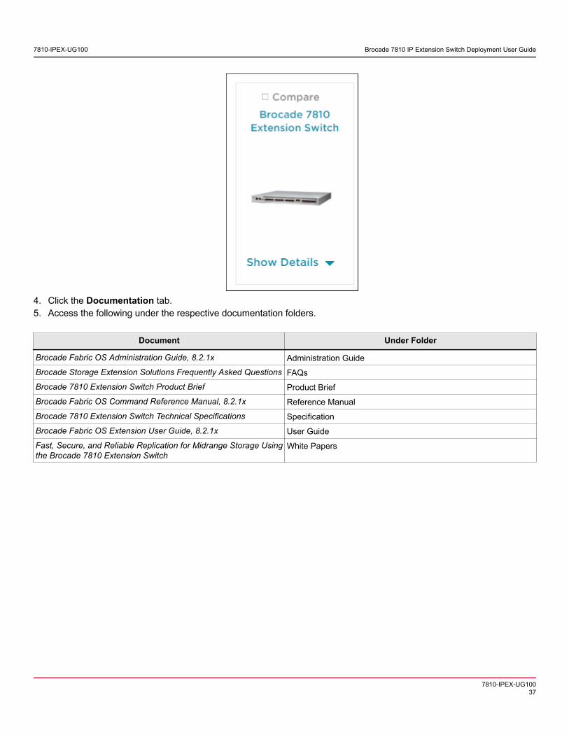
4. Click the Documentation tab.5. Access the following under the respective documentation folders.
Document Under Folder
Brocade Fabric OS Administration Guide, 8.2.1x Administration Guide
Brocade Storage Extension Solutions Frequently Asked Questions FAQs
Brocade 7810 Extension Switch Product Brief Product Brief
Brocade Fabric OS Command Reference Manual, 8.2.1x Reference Manual
Brocade 7810 Extension Switch Technical Specifications Specification
Brocade Fabric OS Extension User Guide, 8.2.1x User Guide
Fast, Secure, and Reliable Replication for Midrange Storage Usingthe Brocade 7810 Extension Switch
White Papers
7810-IPEX-UG100 Brocade 7810 IP Extension Switch Deployment User Guide
7810-IPEX-UG10037

Revision History
7810-IPEX-UG100; 28 February 2019
Initial release.
7810-IPEX-UG100 Brocade 7810 IP Extension Switch Deployment User Guide
7810-IPEX-UG10038


![[7810]Scheda Tecnica Pareti W11 - novità](https://img.dokumen.tips/doc/110x75/5572007c49795991699f83b9/7810scheda-tecnica-pareti-w11-novita.jpg)


![Redirect Splash Page Redirect[1]](https://img.dokumen.tips/doc/110x75/54ff1faf4a7959592e8b5354/redirect-splash-page-redirect1.jpg)