Embed Size (px)
Citation preview

*Tel.: #001-408-927-2461; fax: #001-408-927-2100.E-mail address: [email protected] (J. StoK hr)
Journal of Magnetism and Magnetic Materials 200 (1999) 470}497
Exploring the microscopic origin of magnetic anisotropies withX-ray magnetic circular dichroism (XMCD) spectroscopy
J. StoK hr*
IBM Research Division, Almaden Research Center, 650 Harry Road, San Jose, CA 95120-6099, USA
Received 11 February 1999; received in revised form 13 April 1999
Abstract
Symmetry breaking and bonding at interfaces leads to a variety of anisotropy phenomena in transition metalsandwiches and multilayers. The charge density, the spin density and the orbital moment become anisotropic. Thesee!ects can be studied by the X-ray magnetic circular dichroism (XMCD) technique which senses the local anisotropy ofcharge, spin and angular momentum around an atom that is excited by the absorption of polarized X-rays. Here webrie#y review the principles of the technique and then apply it to the study of the thickness-dependent electronic andmagnetic properties of a Co "lm sandwiched between Au. The experimental results are compared to those obtained byelectronic structure calculations for a free Co monolayer and a Co monolayer sandwiched between Au. In particular,a simple ligand "eld model is developed which allows one to visualize the origin of the magnetocrystalline anisotropy interms of the preferred direction of the orbital moment, corresponding to the direction of maximum size. The modelsupports the intuitive picture that the orbital moment on an atom becomes anisotropic through quenching e!ects by theanisotropic ligand "elds of the neighbors. ( 1999 Elsevier Science B.V. All rights reserved.
Keywords: Anisotropy; Symmetry breaking; X-rays; Monolayers
1. Introduction
Transition metal thin "lms and surfaces mayexhibit a variety of interesting magnetic phe-nomena such as enhanced spin and orbitalmagnetic moments [1}10], or enhanced magneticanisotropies [11], e.g. perpendicular magnetic an-isotropy (PMA) [12}16]. Such e!ects have theirmicroscopic origin in the reduced symmetry experi-enced by magnetic atoms near interfaces or surfa-ces. Of particular interest from a technological
point of view is the large PMA often found inarti"cially layered structures or the large perpen-dicular or in-plane uniaxial anisotropies in chemic-ally ordered alloys with superlattice structures[17}20]. Such systems are also of great scienti"cinterest in that they allow the exploration of one ofthe most important yet still poorly understoodmagnetic phenomena, the origin of magnetocrystal-line anisotropy (MCA). Historically, it has beendi$cult to obtain a clear picture of the origin of theMCA because of its small size [21]. Even today theeasy [1 1 1] magnetization direction of bulk FCCNi cannot be accounted for by means of electronicstructure calculations [22]. Van Vleck [23] "rstproposed the MCA to arise from the spin}orbit
0304-8853/99/$ - see front matter ( 1999 Elsevier Science B.V. All rights reserved.PII: S 0 3 0 4 - 8 8 5 3 ( 9 9 ) 0 0 4 0 7 - 2

1The one-electron diagram shown in Fig. 1 is misleading,especially to the photoemission community, in that it depicts thespin}orbit splitting of the p core shell as an &initial state' e!ect. Inthe proper description based on a conxguration picture, an atomis excited from a ground or initial state con"guration to anexcited or "nal state con"guration. While in general the oneelectron and con"guration pictures are not equivalent, equiva-lence does exist for the case of a d9 ground state, as discussed inRef. [54]. This, in fact, justi"es the use of the one electron model.
interaction which couples the isotropic spin mo-ment to the lattice. In todays electronic structurecalculations the magnetocrystalline anisotropyenergy corresponds to the largest di!erence of thespin}orbit energy when the sample is magnetizedalong two di!erent crystallographic directions. Inthe absence of shape anisotropy e!ects, the twodirections then de"ne the &hard' versus the &easy'magnetization directions.
In general, the complexity of electronic band-structure calculations impedes simple physical in-sight. In the case of layered thin "lms, however, theinherent in-plane/out-of-plane asymmetry and theresulting enhancement of the MCA by orders ofmagnitude [24] suggest exploration of a di!erent,more intuitive, concept based on anisotropic bond-ing or ligand "elds, as previously suggested byWang et al. [25,26]. In addition, it is di$cult topicture the origin of &energy anisotropy'. Since ourvisualization of magnetism is closely related tomagnetic moments it would be preferable to castanisotropy concepts in terms of &moment aniso-tropies'. In the present paper we will explore such&ligand "eld' and &moment' concepts.
The opportunity to directly observe the MCA asan anisotropy of the orbital moment, "rst suggestedby Bruno [11,24], comes from the development ofa powerful new magnetics technique called X-raymagnetic circular dichroism (XMCD) spectro-scopy. The technique was pioneered by SchuK tz andcoworkers in 1987 [27] and over the last ten yearshas been developed both experimentally [4,8,28}37] and theoretically [5,6,38}45] into a quantit-ative magnetometry tool. It has several capabilitiesnot a!orded by traditional magnetics techniques[46]. Its foremost strengths are the element-speci-"c, quantitative separation and determination ofspin and orbital magnetic moments and their an-isotropies. These capabilities are highlighted in thepresent paper. Other strengths, which will not befurther discussed here, are its chemical sensitivity[16,47], its ability to identify moment orientationsin ultrathin "lms and monolayer magnetic mater-ials [48] which leads to its element-speci"c mag-netic imaging capability [49], its ability to obtainelement speci"c AC susceptibilities [50] and mag-netization loops [51], and its sub-monolayer sensi-tivity [33,52,53].
The structure of the paper is as follows. Theprinciples of XMCD spectroscopy will be reviewedin Section 2. In Section 3 XMCD results fora Au/Co/Au wedge with Co thickness ranging from3 to 12 layers will be presented. In Section 4 theorigin of anisotropy e!ects is discussed in terms ofelectronic structure calculations and a simpleligand "eld model. The XMCD results are dis-cussed in terms of theoretical expectations in Sec-tion 5. Conclusions are presented in Section 6.
2. XMCD spectroscopy
2.1. XMCD spectroscopy in 3d transition metals
Here we shall brie#y review the principles ofXMCD spectroscopy. For more detailed accountsthe reader is referred to earlier works [54}56]. Themagnetic properties of the 3d transition metals aremainly determined by their d valence electrons[57,58]. In the ferromagnets Fe, Co and Ni thed shell becomes increasingly "lled, resulting in a de-creasing number of d holes, N. The spin magneticmoment due to the exchange interaction is simplythe di!erence between the number of spin-up andspin-down holes, m
4"!2SS
zTk
B/+"(N
t!
Ns)k
B. The orbital moment m
0"!S¸
zTk
B/+
arises from the spin}orbit interaction which is sig-ni"cantly smaller (&50 meV) than the exchangeinteraction (&1 eV) and the 3d bandwidth (afew eV). Therefore, the orbital moment (e.g.m
0"0.14 l
Bfor Co) is much smaller than the spin
moment (e.g. m4"1.64 l
Bfor Co).
The properties of 3d-electrons are best probed inan X-ray absorption experiment by excitation of 2pcore electrons to un"lled 3d states as illustrated bya simple one-electron picture1 in Fig. 1a. In
J. Sto( hr / Journal of Magnetism and Magnetic Materials 200 (1999) 470}497 471

Fig. 1. (a) Electronic transitions in conventional L-edge X-ray absorption, (b) and (c) X-ray magnetic circular dichroism, illustrated ina one-electron model. The transitions occur from the spin}orbit split 2p core shell to empty conduction band states above the Fermilevel. In conventional X-ray absorption the transition intensity measured as the white line intensity I
L3#I
L2is proportional to the
number of d holes, N. By use of circularly polarized X-rays the spin moment (b), and orbital moment (c), can be determined from thedichroic di!erence intensities A and B, as explained in the text.
principle, L-edge X-ray absorption spectra containcontributions from both pPd and pPstransitions, but in practice the pPd channel dom-inates by a factor '20 [59]. The sum of the whiteline intensities, denoted I
L3and I
L2, respectively, is
directly proportional to the number of d holes. Thiscorrelation follows from one of the several intensitysum rules [38,39,41] to be discussed below. The useof circularly polarized X-rays opens the door formagnetic studies. The underlying physics is most
easily understood in the following two-step picture[54,55].
In the xrst step, right or left circularly polarizedphotons transfer their angular momentum, + and!+, respectively, to the excited photoelectron. Ifthe photoelectron originates from a spin}orbit splitlevel, e.g. the p
3@2level (L
3edge), the angular mo-
mentum of the photon can be transferred in part tothe spin through the spin}orbit coupling. Rightcircularly polarized photons transfer the opposite
472 J. Sto( hr / Journal of Magnetism and Magnetic Materials 200 (1999) 470}497
momentum to the electron than left circularlypolarized photons, and hence photoelectrons withopposite spins are created in the two cases. Sincethe p
3@2(L
3) and p
1@2(L
2) levels have opposite
spin-orbit coupling (l#s and l!s, respectively),the spin polarization will be opposite at the twoedges. In the "rst (absorption) step, &spin-up'and &spin-down' are de"ned relative to thephoton helicity or photon spin, which is parallel(right) or antiparallel (left) to the X-ray propagationdirection. The handeness of circularly polarizedlight is not uniquely de"ned. We follow Feynmanand the convention used in particle physics. SeeRef. [60].
The magnetic properties enter in the second step.Here the spin-split valence shell acts as a detectorfor the spin of the excited photoelectron. Thequantization axis of the detector is given by themagnetization direction which, for maximum dich-roism e!ect, needs to be aligned with the photonspin direction. As illustrated in Fig. 1 we shalldenote the di!erences of the white line intens-ities recorded with right and left circular polariza-tion, i.e. the XMCD intensities, as A (L
3edge)
and B (L2
edge), respectively. Note that A andB have opposite sign, re#ecting the oppositespin}orbit coupling of the p
3@2and p
1@2levels.
A powerful sum rule [39] links the spin momentquantitatively to the measured intensity A!2B, asdiscussed below.
Similarly, if the d valence shell possesses an or-bital moment, as shown in Fig. 1c, it will act asan orbital momentum detector for the excitedphotoelectron. By summing over the L
3, i.e. (l#s),
and L2, i.e. (l!s), intensities it is apparent that the
spin s is eliminated and one measures the orbitalmoment of the valence shell, as schematicallyshown in Fig. 1c. This is expressed by the orbitalmoment sum rule [38] which links the orbital mo-ment in the d shell to the dichroism intensityA#B.
In the above discussion we have assumedthat the magnetization direction is "xed so thatthe XMCD intensity is the di!erence intensity,obtained for two X-ray helicities. It is easy toshow that it is equivalent to "x the X-ray heli-city and switch the magnetization direction[54].
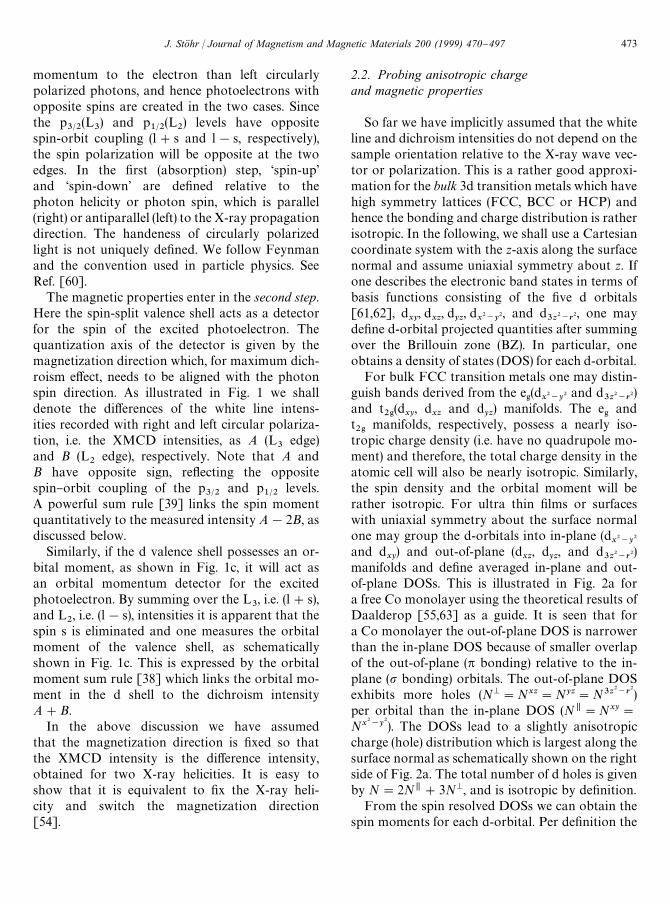
2.2. Probing anisotropic chargeand magnetic properties
So far we have implicitly assumed that the whiteline and dichroism intensities do not depend on thesample orientation relative to the X-ray wave vec-tor or polarization. This is a rather good approxi-mation for the bulk 3d transition metals which havehigh symmetry lattices (FCC, BCC or HCP) andhence the bonding and charge distribution is ratherisotropic. In the following, we shall use a Cartesiancoordinate system with the z-axis along the surfacenormal and assume uniaxial symmetry about z. Ifone describes the electronic band states in terms ofbasis functions consisting of the "ve d orbitals[61,62], d
xy, d
xz, d
yz, d
x2~y
2, and d3z2~r
2, one mayde"ne d-orbital projected quantities after summingover the Brillouin zone (BZ). In particular, oneobtains a density of states (DOS) for each d-orbital.
For bulk FCC transition metals one may distin-guish bands derived from the e
'(d
x2~y
2 and d3z2~r
2)and t
2'(d
xy, d
xzand d
yz) manifolds. The e
'and
t2'
manifolds, respectively, possess a nearly iso-tropic charge density (i.e. have no quadrupole mo-ment) and therefore, the total charge density in theatomic cell will also be nearly isotropic. Similarly,the spin density and the orbital moment will berather isotropic. For ultra thin "lms or surfaceswith uniaxial symmetry about the surface normalone may group the d-orbitals into in-plane (d
x2~y
2
and dxy
) and out-of-plane (dxz
, dyz, and d
3z2~r2)
manifolds and de"ne averaged in-plane and out-of-plane DOSs. This is illustrated in Fig. 2a fora free Co monolayer using the theoretical results ofDaalderop [55,63] as a guide. It is seen that fora Co monolayer the out-of-plane DOS is narrowerthan the in-plane DOS because of smaller overlapof the out-of-plane (p bonding) relative to the in-plane (p bonding) orbitals. The out-of-plane DOSexhibits more holes (NM"Nxz"Nyz"N3z2~r
2)per orbital than the in-plane DOS (N,"Nxy"
Nx2~y
2). The DOSs lead to a slightly anisotropiccharge (hole) distribution which is largest along thesurface normal as schematically shown on the rightside of Fig. 2a. The total number of d holes is givenby N"2N,#3NM, and is isotropic by de"nition.
From the spin resolved DOSs we can obtain thespin moments for each d-orbital. Per de"nition the
J. Sto( hr / Journal of Magnetism and Magnetic Materials 200 (1999) 470}497 473

474 J. Sto( hr / Journal of Magnetism and Magnetic Materials 200 (1999) 470}497

b
Fig. 2. Illustration of the origin of charge, spin and orbital moment anisotropies in an ultrathin "lm using a free Co monolayer as anexample [63]. (a) The bonding anisotropy is re#ected by di!erent densities of states for the in-plane and out-of-plane d orbitals. This leadsto di!erent numbers of unoccupied states above the Fermi level, i.e. the number of in-plane N@@ and out-of-plane NM holes, as shown shaded.The total number of d holes N"2N,#3NM, is isotropic per de"nition. (b) Same as (a) for the spin-resolved densities of states. The totalspin moment, m
4"2m,
4#3mM
4, is isotropic per de"nition. (c) Origin of the orbital magnetic moment illustrated in a d-orbital based
bonding model [55]. If the bonding is anisotropic, as in the case of a multilayer, the energetic splitting between the in-plane andout-of-plane d orbitals will be di!erent. In the presence of spin}orbit coupling the resulting orbital moment will be anisotropic.
spin moment is the di!erence between the numberof electrons in the majority band and the minorityband. Neglecting hybridization e!ects betweend electrons with the s and p electrons [6] one mayalso de"ne the spin moment as the di!erence be-tween the number of holes in the minority band andthe majority band (note opposite sign) so that, withthe de"nition of Fig. 1b and Fig. 2b, mi
4"
(Nit!Ni
s)k
Bfor each d
iorbital. As shown in
Fig. 2b for a Co monolayer the out-of-plane(mM
4"mxz
4"myz
4"m3z2~r
2
4) spin moment is found
to be larger than the in-plane (m,4"mxy
4"mx
2~y2
4)
one. The total isotropic spin moment is given bym
4"2m,
4#3mM
4. In the transition metals Fe, Co
and Ni there is a close correspondence between theanisotropy of charge and spin because the majorityband is nearly full, as indicated in Figs. 2a and b. Inpractice, the anisotropy of the spin density is foundto be larger than in the charge density becauseopposite minority and majority band contributionsenhance the di!erence [55,63].
While the anisotropy of the charge and the spinis determined by the xlling of the in-plane andout-of-plane sub-bands, i.e. the number of holes,the orbital moment anisotropy greatly depends onthe in-plane versus out-of-plane bandwidth as illus-trated in Fig. 2c. The orbital moment arises mainlyfrom the minority band since a "lled band has nonet orbital moment. Its value is determined by theaverage bandwidth= which determines the aver-age separation of the "lled and empty minorityband states that are mixed by the small spin}orbitinteraction. A perturbation treatment gives m
0J
m/=, where m&70 meV is the spin}orbit couplingconstant. Because the orbital moment direction isperpendicular to the plane of the orbiting hole orelectron the in-plane moment m,
0is determined by
the out-of-plane orbitals and their bandwidth. Thesmaller out-of-plane bandwidth therefore leads to
a larger in-plane orbital moment as indicated onthe right side of Fig. 2c.
The polarized nature of X-rays allows one toquantitatively probe the various electronic andmagnetic anisotropies, as discussed below.
2.3. Sum rules
2.3.1. ChargePolarized X-rays are intrinsically anisotropic.
For linearly polarized X-rays the electric "eld vec-tor E de"nes a direction (axis) in space and right-and left-handed circularly polarized photons arecharacterized by a helicity vector which pointseither into the X-ray propagation direction k oralong !k. This anisotropy of polarized X-raysleads to a search light e!ect and allows the detec-tion of anisotropic charge and moment distribu-tions in magnetic thin "lms. Three sum rules relatethe measured intensities I
L3, I
L2, A and B, de"ned in
Fig. 1, to the electronic and magnetic properties ofthe sample. The "rst sum rule is related to thecharge distribution and is given by [41],
[IL3#I
L2]a"C(N#Na
Q), (1)
where C is the square of the pPd radial transitionmatrix element and has a value of about 10 Mb eV[56]. We have characterized the anisotropy by anindex a that speci"es the orientation of E (linearpolarization) or k (circular polarization). In thefollowing a may either denote the coordinate axesx, y or z or the polar angle from the z-axis asde"ned in Fig. 2. Eq. (1) correlates the polarizationdependent white line intensity with the total num-ber of d holes N"2N,#3NM and a quadrupoleterm Na
Qwhich expresses the anisotropy of the
charge density in the unit cell [41]. The origin ofthis term is discussed in more detail in Appendix A.The sum rule expression N#Na
Q"N
%&&can be
J. Sto( hr / Journal of Magnetism and Magnetic Materials 200 (1999) 470}497 475

written as a linear combination of N, and NM [55].For linear polarization a speci"es the E directionand a"03 corresponds to Eoz and a"903 corre-sponds to EEz (see Fig. 2a) and we obtain
Eoz: N%&&"2NM#3N,,
EEz: N%&&"5NM. (2)
For circular or plane polarization a speci"es thek direction and a"03 corresponds to kEz anda"903 corresponds to koz (see Fig. 2a), and weobtain
kEz: N%&&"2NM#3N,,
koz: N%&&"3.5NM#1.5N,. (3)
The term NaQ
vanishes when an angular averageis performed, 1
3+aNa
Q"(Nx
Q#Ny
Q#Nz
Q)/3"0. In
this case the isotropic sum rule IL3#I
L2"CN is
obtained.
2.3.2. SpinFor 3d transition metals the spin}orbit coupling
is small and the charge distribution is not signi"-cantly altered if the spin is rotated by an externalmagnetic "eld. As a consequence the anisotropy ofthe spin density is related to that of the chargedensity. In the following, we shall assume that in allmeasurements the sample is magnetically saturatedby a strong external magnetic "eld along the X-raypropagation direction. The spin sum rule [39] isthen given by [41]
[A!2B]a"!
C
kB
(m4#ma
D) (4)
and it closely resembles the charge sum rule [55].The total number of holes, N, is simply replaced bythe isotropic spin moment m
4"2m,
4#3mM
4, and
the charge density term NaQ
is replaced by a spindensity term ma
D, also called an intra-atomic mag-
netic dipole moment [39,41]. This term, discussedin more detail in Appendix B, is non-zero in aniso-tropic bonding environments and re#ects the factthat the number of spins in the unit cell di!ersalong di!erent crystallographic directions. The sumrule term m
4#ma
Dis again given by contributions
of the various d orbitals. For circular polarizationa"03 corresponds to the X-ray wave vector kEzand a"903 corresponds to koz (see Fig. 2b) and
we obtain
koz: m,D"mx
D"my
D"2(mM
4!m,
4),
kEz: mMD"mz
D"4(mE
4!mM
4) (5)
or equivalently,
koz: m4#m,
D"5mM
4kEz: m
4#mM
D"6m,
4!mM
4. (6)
Polarized X-rays therefore o!er the capability ofprobing the angular distribution of the spins in theatomic cell, whereas conventional magnetometryonly probes the integrated number of spins, i.e. theessentially isotropic spin moment per atom. Theterm ma
Dvanishes when an angular average is per-
formed, 13+ama
D"0, and the isotropic sum rule
A!2B"!Cm4/k
Bis obtained [41]. The angular
average requires that in all measurements thesample is magnetically saturated by a strong ex-ternal magnetic "eld along the X-ray propagationdirection.
2.3.3. Orbital momentThe electronic states created by the crystal
potential alone possess no orbital moment, since alld orbitals have a perfect balance of $m
-contri-
butions (see Fig. 13 below) [55]. This balance isbroken by the spin}orbit interaction which mixesdi!erent d orbitals in a way to produce a non-zeroangular momentum [24,55], as illustrated inFig. 2c. If the bonding is anisotropic, the d electroncharge will be anisotropic. When the sample ismagnetized in di!erent directions, i.e. by rotatingthe spin moment by a su$ciently strong externalmagnetic "eld, an orbital moment arises from theclockwise/counterclockwise imbalance of orbitalmotion in the plane perpendicular to the spinquantization axis as a consequence of thespin}orbit coupling. Because of the anisotropiccharge cloud, the orbital amplitudes will di!er fordi!erent magnetization (spin moment) directions,and the orbital moment will be anisotropic. Thedirection of the orbital moment relative to the spinmoment is given by Hund's third rule. For Fe, Coand Ni m
0and m
4are parallel because the d shell is
more than half full. In the presence of an externalmagnetic "eld which is su$ciently large tomagnetically saturate the sample, the orbital
476 J. Sto( hr / Journal of Magnetism and Magnetic Materials 200 (1999) 470}497
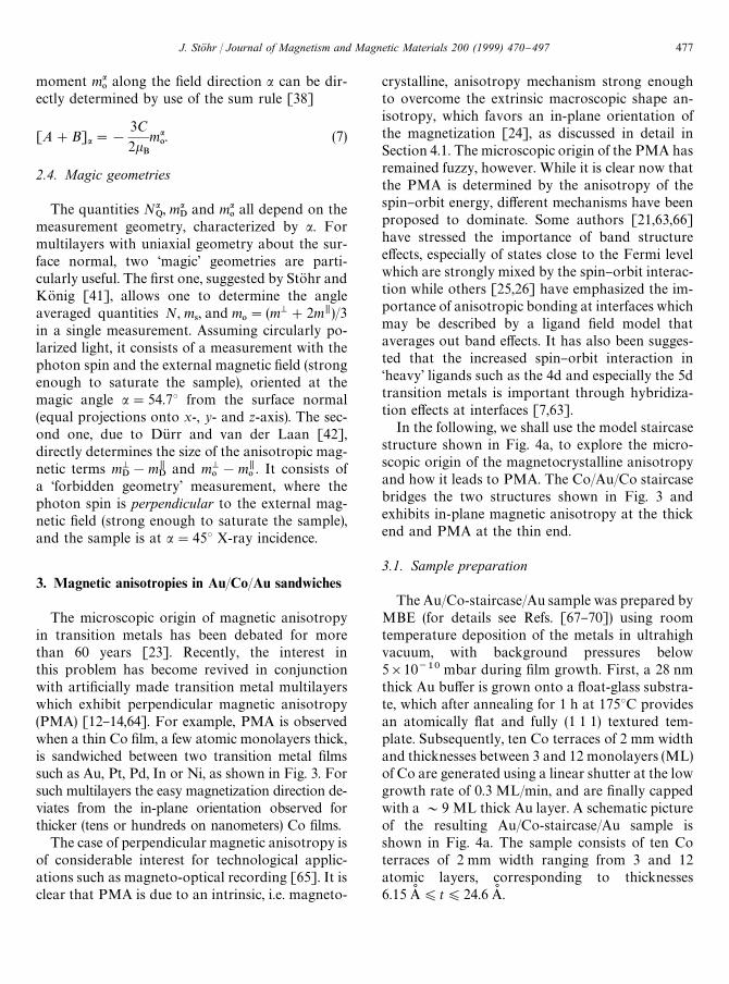
moment ma0
along the "eld direction a can be dir-ectly determined by use of the sum rule [38]
[A#B]a"!
3C
2kB
ma0. (7)
2.4. Magic geometries
The quantities NaQ, ma
Dand ma
0all depend on the
measurement geometry, characterized by a. Formultilayers with uniaxial geometry about the sur-face normal, two &magic' geometries are parti-cularly useful. The "rst one, suggested by StoK hr andKoK nig [41], allows one to determine the angleaveraged quantities N, m
4, and m
0"(mM#2m,)/3
in a single measurement. Assuming circularly po-larized light, it consists of a measurement with thephoton spin and the external magnetic "eld (strongenough to saturate the sample), oriented at themagic angle a"54.73 from the surface normal(equal projections onto x-, y- and z-axis). The sec-ond one, due to DuK rr and van der Laan [42],directly determines the size of the anisotropic mag-netic terms mM
D!m,
Dand mM
0!m,
0. It consists of
a &forbidden geometry' measurement, where thephoton spin is perpendicular to the external mag-netic "eld (strong enough to saturate the sample),and the sample is at a"453 X-ray incidence.
3. Magnetic anisotropies in Au/Co/Au sandwiches
The microscopic origin of magnetic anisotropyin transition metals has been debated for morethan 60 years [23]. Recently, the interest inthis problem has become revived in conjunctionwith arti"cially made transition metal multilayerswhich exhibit perpendicular magnetic anisotropy(PMA) [12}14,64]. For example, PMA is observedwhen a thin Co "lm, a few atomic monolayers thick,is sandwiched between two transition metal "lmssuch as Au, Pt, Pd, In or Ni, as shown in Fig. 3. Forsuch multilayers the easy magnetization direction de-viates from the in-plane orientation observed forthicker (tens or hundreds on nanometers) Co "lms.
The case of perpendicular magnetic anisotropy isof considerable interest for technological applic-ations such as magneto-optical recording [65]. It isclear that PMA is due to an intrinsic, i.e. magneto-
crystalline, anisotropy mechanism strong enoughto overcome the extrinsic macroscopic shape an-isotropy, which favors an in-plane orientation ofthe magnetization [24], as discussed in detail inSection 4.1. The microscopic origin of the PMA hasremained fuzzy, however. While it is clear now thatthe PMA is determined by the anisotropy of thespin}orbit energy, di!erent mechanisms have beenproposed to dominate. Some authors [21,63,66]have stressed the importance of band structuree!ects, especially of states close to the Fermi levelwhich are strongly mixed by the spin}orbit interac-tion while others [25,26] have emphasized the im-portance of anisotropic bonding at interfaces whichmay be described by a ligand "eld model thataverages out band e!ects. It has also been sugges-ted that the increased spin}orbit interaction in&heavy' ligands such as the 4d and especially the 5dtransition metals is important through hybridiza-tion e!ects at interfaces [7,63].
In the following, we shall use the model staircasestructure shown in Fig. 4a, to explore the micro-scopic origin of the magnetocrystalline anisotropyand how it leads to PMA. The Co/Au/Co staircasebridges the two structures shown in Fig. 3 andexhibits in-plane magnetic anisotropy at the thickend and PMA at the thin end.
3.1. Sample preparation
The Au/Co-staircase/Au sample was prepared byMBE (for details see Refs. [67}70]) using roomtemperature deposition of the metals in ultrahighvacuum, with background pressures below5]10~10 mbar during "lm growth. First, a 28 nmthick Au bu!er is grown onto a #oat-glass substra-te, which after annealing for 1 h at 1753C providesan atomically #at and fully (1 1 1) textured tem-plate. Subsequently, ten Co terraces of 2 mm widthand thicknesses between 3 and 12 monolayers (ML)of Co are generated using a linear shutter at the lowgrowth rate of 0.3 ML/min, and are "nally cappedwith a &9 ML thick Au layer. A schematic pictureof the resulting Au/Co-staircase/Au sample isshown in Fig. 4a. The sample consists of ten Coterraces of 2 mm width ranging from 3 and 12atomic layers, corresponding to thicknesses6.15 As )t)24.6 As .
J. Sto( hr / Journal of Magnetism and Magnetic Materials 200 (1999) 470}497 477

Fig. 3. Illustration of magnetic anisotropies in two often encountered cases. In magnetic "lms with a thickness exceeding about 2 nm theeasy magnetization direction is typically found to be in-plane due to the dominance of the magnetostatic shape anisotropy. In multilayersystems, consisting of ultrathin alternating magnetic (sub-nanometer thickness) and non-magnetic layers, such as Co and Au, discussedin this paper, the easy axis may be out-of-plane due to the dominance of the spin}orbit derived magnetocrystalline anisotropy.
3.2. Kerr results
The Co staircase was characterized by angle-dependent polar Kerr hysteresis measurements in"elds up to 20 kOe [7]. Plateaus in both the co-ercivity and the Kerr rotation con"rmed its steplikestructure as shown in Fig. 4b. The intrinsic energyanisotropy (per Co volume), K
1, was found to fol-
low a KV#2K
S/t dependence, as shown in Fig. 4c,
with volume and surface anisotropy constantsK
V"0.45 MJ/m3 and K
S"3.4 MJ/m3"0.70 mJ/
m2, respectively. By extrapolation we obtain for theenergy anisotropy of a monolayer of Cosandwiched between Au E
40"!7.3 MJ/m3"
!5.1]10~4 eV/atom. The size of KV
togetherwith the observation of a second-order anisotropyconstant K
2"0.1}0.2 MJ/m3 are consistent with
mostly hexagonal (0 0 0 1)Co. With these anisot-
ropy constants, the transition from out-of-plane toin-plane anisotropy occurs at t+11 ML [35].
3.3. XMCD measurements
XMCD measurements were performed at roomtemperature at the Stanford Synchrotron Radi-ation Laboratory (SSRL) on beamline 8-2. Circu-larly polarized X-rays were obtained by moving thepre-focusing mirror below the electron orbitalplane, yielding a degree of polarization of 90$5%.The X-ray absorption was measured by the photo-current from the sample [55] using right circularlypolarized X-rays and switching the magnetizationdirection parallel and then antiparallel to thephoton spin at each photon energy step.
The XMCD spectra were recorded in a 10 kOeexternal magnetic "eld oriented parallel to the X-ray
478 J. Sto( hr / Journal of Magnetism and Magnetic Materials 200 (1999) 470}497
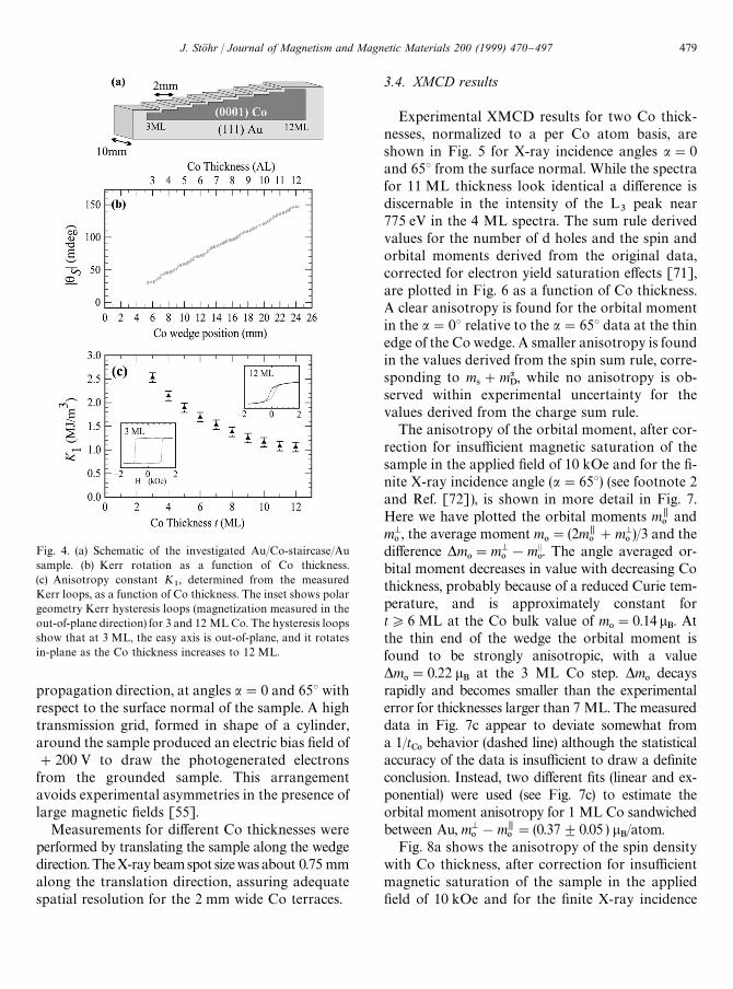
Fig. 4. (a) Schematic of the investigated Au/Co-staircase/Ausample. (b) Kerr rotation as a function of Co thickness.(c) Anisotropy constant K
1, determined from the measured
Kerr loops, as a function of Co thickness. The inset shows polargeometry Kerr hysteresis loops (magnetization measured in theout-of-plane direction) for 3 and 12 ML Co. The hysteresis loopsshow that at 3 ML, the easy axis is out-of-plane, and it rotatesin-plane as the Co thickness increases to 12 ML.
propagation direction, at angles a"0 and 653 withrespect to the surface normal of the sample. A hightransmission grid, formed in shape of a cylinder,around the sample produced an electric bias "eld of#200 V to draw the photogenerated electronsfrom the grounded sample. This arrangementavoids experimental asymmetries in the presence oflarge magnetic "elds [55].
Measurements for di!erent Co thicknesses wereperformed by translating the sample along the wedgedirection.TheX-raybeamspot sizewasabout 0.75 mmalong the translation direction, assuring adequatespatial resolution for the 2 mm wide Co terraces.
3.4. XMCD results
Experimental XMCD results for two Co thick-nesses, normalized to a per Co atom basis, areshown in Fig. 5 for X-ray incidence angles a"0and 653 from the surface normal. While the spectrafor 11 ML thickness look identical a di!erence isdiscernable in the intensity of the L
3peak near
775 eV in the 4 ML spectra. The sum rule derivedvalues for the number of d holes and the spin andorbital moments derived from the original data,corrected for electron yield saturation e!ects [71],are plotted in Fig. 6 as a function of Co thickness.A clear anisotropy is found for the orbital momentin the a"03 relative to the a"653 data at the thinedge of the Co wedge. A smaller anisotropy is foundin the values derived from the spin sum rule, corre-sponding to m
4#ma
D, while no anisotropy is ob-
served within experimental uncertainty for thevalues derived from the charge sum rule.
The anisotropy of the orbital moment, after cor-rection for insu$cient magnetic saturation of thesample in the applied "eld of 10 kOe and for the "-nite X-ray incidence angle (a"653) (see footnote 2and Ref. [72]), is shown in more detail in Fig. 7.Here we have plotted the orbital moments m,
0and
mM0, the average moment m
0"(2m,
0#mM
0)/3 and the
di!erence *m0"mM
0!mE
0. The angle averaged or-
bital moment decreases in value with decreasing Cothickness, probably because of a reduced Curie tem-perature, and is approximately constant fort*6 ML at the Co bulk value of m
0"0.14l
B. At
the thin end of the wedge the orbital moment isfound to be strongly anisotropic, with a value*m
0"0.22 l
Bat the 3 ML Co step. *m
0decays
rapidly and becomes smaller than the experimentalerror for thicknesses larger than 7 ML. The measureddata in Fig. 7c appear to deviate somewhat froma 1/t
C0behavior (dashed line) although the statistical
accuracy of the data is insu$cient to draw a de"niteconclusion. Instead, two di!erent "ts (linear and ex-ponential) were used (see Fig. 7c) to estimate theorbital moment anisotropy for 1 ML Co sandwichedbetween Au, mM
0!m,
0"(0.37$0.05 ) l
B/atom.
Fig. 8a shows the anisotropy of the spin densitywith Co thickness, after correction for insu$cientmagnetic saturation of the sample in the applied"eld of 10 kOe and for the "nite X-ray incidence
J. Sto( hr / Journal of Magnetism and Magnetic Materials 200 (1999) 470}497 479
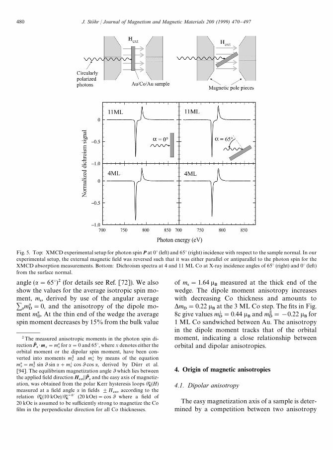
Fig. 5. Top: XMCD experimental setup for photon spin P at 03 (left) and 653 (right) incidence with respect to the sample normal. In ourexperimental setup, the external magnetic "eld was reversed such that it was either parallel or antiparallel to the photon spin for theXMCD absorption measurements. Bottom: Dichroism spectra at 4 and 11 ML Co at X-ray incidence angles of 653 (right) and 03 (left)from the surface normal.
2The measured anisotropic moments in the photon spin di-rection PK a )mx
"maxfor a"0 and 653, where x denotes either the
orbital moment or the dipolar spin moment, have been con-verted into moments m,
xand mM
xby means of the equation
max"m,
xsin 0 sin a#mM
xcos 0 cos a, derived by DuK rr et al.
[94]. The equilibrium magnetization angle 0 which lies betweenthe applied "eld direction H
%95DDPK a and the easy axis of magnetiz-
ation, was obtained from the polar Kerr hysteresis loops haK(H)
measured at a "eld angle a in "elds $H%95
, according to therelation ha
K(10 kOe)/ha/03
K(20 kOe)"cos 0 where a "eld of
20 kOe is assumed to be su$ciently strong to magnetize the Co"lm in the perpendicular direction for all Co thicknesses.
angle (a"653)2 (for details see Ref. [72]). We alsoshow the values for the average isotropic spin mo-ment, m
4, derived by use of the angular average
+amaD"0, and the anisotropy of the dipole mo-
ment maD. At the thin end of the wedge the average
spin moment decreases by 15% from the bulk value
of m4"1.64 l
Bmeasured at the thick end of the
wedge. The dipole moment anisotropy increaseswith decreasing Co thickness and amounts to*m
D"0.22 l
Bat the 3 ML Co step. The "ts in Fig.
8c give values mMD"0.44 l
Band m,
D"!0.22 l
Bfor
1 ML Co sandwiched between Au. The anisotropyin the dipole moment tracks that of the orbitalmoment, indicating a close relationship betweenorbital and dipolar anisotropies.
4. Origin of magnetic anisotropies
4.1. Dipolar anisotropy
The easy magnetization axis of a sample is deter-mined by a competition between two anisotropy
480 J. Sto( hr / Journal of Magnetism and Magnetic Materials 200 (1999) 470}497

3When the magnetization distribution in the unit cell is ex-panded in multipoles the dipole}dipole interaction has the gen-eral form of Eq. (8) but the size of the moments m
iis given by the
multipole expansion mi"m
4#ma
D/2#2 . The monopole term
m4gives Eq. (8), the quadrupole term ma
D/2 makes a contribution
of order maD/2m
4.
Fig. 6. Sum rule derived white line (a), spin moment (b), andorbital moment (c) values as a function of Co layer thickness forincidence angles a"0 and 653 from the surface normal of thecircularly polarized X-rays. The data have been corrected forelectron yield saturation e!ects [71].
mechanisms arising from the magnetostaticdipole}dipole coupling of the magnetization distri-butions within the individual atomic cells, i.e. themagnetic moment densities, and from the spin}or-bit interaction [24]. In general, the magnetizationdistribution in the atomic cells contains spin andorbital contributions and it is not spherical butinvolves various multipoles. In the multipole ex-pansion of the spin density3 the largest (monopole)term, after integration over the atomic volume,corresponds to the magnetic spin moment. Since itarises from the exchange interaction the spin mo-ment is intrinsically isotropic and magnetic anisot-ropy arises only from the preferred dipolarcoupling between the atomic moments. The mono-pole term in the spin density therefore gives rise tothe conventional dipole}dipole interaction betweenmagnetic moments m
4, located at the atomic posi-
tions in the lattice,
E$*1~$*1
"
k0
4p+iEj
1
r3ijCm
i)m
j!3
(rij)m
i)(r
ij)m
j)
r2ij
D. (8)
The summation is over all atomic dipoles miand
mj, whose absolute values are given by the spin
moment m4. Every pair of dipoles is only counted
once, and rij
is the vector connecting the two mo-ments. The next higher (quadrupole) term in themultipole expansion of the spin density re#ectsthe lowest-order anisotropic spin distribution inthe atomic cell and it gives rise to the intra-atomicmagnetic dipole moment m
Ddiscussed in conjunc-
tion with the spin sum rule (see also Appendix B).The orbital moment also contributes to the mag-netization density in the atomic volume and itsanisotropy is typically comparable to that of theintra-atomic magnetic dipole moment, as seen fromFigs. 7 and 8. Since the anisotropies of ma
0and
maD
are much smaller than the spin moment m4, in
practice, the contributions of the anisotropic
ma0and ma
Dterms to the magnetostatic energy can be
neglected and it is su$cient to consider the lowest-order magnetic dipole}dipole interaction given byEq. (8).
Remembering that all moments are parallel be-cause of the dominant exchange interaction, thedipole}dipole energy between two magneticdipoles, for example, is smallest when both atomicmoments align parallel along the internuclear axis.For a thin "lm the internuclear axes are preferen-tially oriented in the plane of the sample and the
J. Sto( hr / Journal of Magnetism and Magnetic Materials 200 (1999) 470}497 481
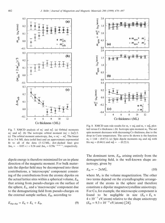
Fig. 7. XMCD analysis of mM0
and m,0. (a) Orbital moments
mM0
and m,0. (b) The isotropic orbital moment (mM
0#2m,
0)/3.
(c) The orbital moment anisotropy, *m0,mM
0!m@@
0. The linear
"t to 3}6 ML data (solid line) and an approximate exponential"t to all of the data (3}12 ML; dot}dashed line) give*m
0"!0.05]t#0.36 and *m
0"0.59e~0.41Ct, respectively.
Fig. 8. XMCD sum rule results for m4#mM
Dand m
4#m,
D, plot-
ted versus Co thickness t. (b) Isotropic spin moment m4. The net
spin moment decreases with decreasing Co thickness, due to thedrop in Curie temperature. The curve "t shown is the functionm
4"1.64!(0.67/t). (c) Spin dipole moments mM
Dand m@@
Dwith
"ts mMD"(0.44/t) and m,
D"!(0.22/t).
dipole energy is therefore minimized for an in-planedirection of the magnetic moment. For bulk mater-ials the dipolar "eld may be decomposed into threecontributions, a µscopic' component consist-ing of the contributions from the atomic dipoles onthe actual lattice sites within a spherical volume, E
S,
that arising from pseudo-charges on the surface ofthe sphere, E
L, and a ¯oscopic' component due
to the demagnetizing "eld from pseudo-charges onthe external sample surface, E
D, according to
E$*1}$*1
"ES#E
L#E
D. (9)
The dominant term, ED, arising entirely from the
demagnetizing "eld, is the well-known shape an-isotropy, given by
ED"!2pM2
V, (10)
where MV
is the volume magnetization. The othertwo terms depend on the crystallographic arrange-ment of the atoms in the sphere and thereforeconstitute a dipolar magnetocrystalline anisotropy.For Co, for example, the microscopic component isfound to be negligible in size (E
S#E
L+
4]10~7 eV/atom) relative to the shape anisotropy(E
D"9.3]10~5 eV/atom) [24].
482 J. Sto( hr / Journal of Magnetism and Magnetic Materials 200 (1999) 470}497
4Note that *E40"!K
1with the convention E
40"
K0#K
1sin2 h used by Bruno [24].
For surfaces and ultrathin "lms the anisotropymay be calculated by a two-dimensional lattice sum[73]. Typical anisotropy energies are )5]10~5 eV/atom for a single ferromagnetic layer,smaller than those observed experimentally [24].Therefore, the magnetocrystalline anisotropy, ingeneral, and the PMA, in particular, cannot beaccounted for by a dipolar anisotropy. Instead,they arise from spin}orbit coupling as suggested byVan Vleck [23].
4.2. Spin}orbit anisotropy
Todays electronic structure calculations accountfor Hund's "rst rule (maximum spin) by using thelocal spin-density approximation for the exchangesplitting. However, such theories do not adequatelyaccount for Hund's second rule (maximum orbitalmomentum) and this de"ciency leads to orbitalmoments that are too small. Eriksson et al. [57,74]have proposed an orbital enhancement term thatleads to much better agreement between theory andexperiment. Hund's third rule (total angular mo-mentum) is accounted for by treating the spin}orbitinteraction either fully relativistically [75,76] or byperturbation methods [11,21,25]. In particular, thesmall MCA energies correspond to the energeticdi!erence obtained by two calculations with thespin direction chosen along two orthogonal crystal-lographic axes, corresponding to the easy and hardmagnetization directions.
Owing to the complexity of electronic structurecalculations it is di$cult to obtain a simple physicalpicture that catches the essence of the magnetocrys-talline anisotropy mechanism. For the bulktransition metals Fe, Co and Ni the crystal sym-metries are high and the MCAs are extremely small(10~6 eV/atom) so that insight into the origin of theanisotropy mechanism is nearly impossible to ob-tain [21,22]. In contrast, the MCA in anisotropicsystems like monolayers and multilayer systems islarger by orders of magnitude (10~4 eV/atom), sug-gesting a possible interpretation of the MCA basedon symmetry breaking and asymmetric bonding atthe magnetic surfaces or interfaces. Such an inter-pretation is supported by the preference for PMAin many multilayer systems, independent of thedetailed crystallographic structure of the layers.
A symmetry-based model has indeed been sugges-ted by Wang et al. [25,26] who compared "rstprinciples band structure results with those ob-tained from a more intuitive ligand "eld model thataccounts for the di!erent in-plane and out-of-planebonding at surfaces and interfaces. The ligand "eldapproach used by Wang et al. was based on com-parison of spin}orbit energies for in-plane versusout-of-plane orientations of the spin.
Bruno [11,24] has shown that under certain as-sumptions the anisotropy of the spin}orbit energy isdirectly related to the anisotropy of the orbitalmoment according to
*E40"C(m,
0!mM
0), (11)
where C'0 is a proportionality constant. Bruno'swork followed careful high "eld measurements ofthe anisotropy of the total (spin plus orbital) mag-netic moment by Aubert, Rebouillat, Escudier andPauthenet [77}80]. The relationship between theorbital moment and the magnetic anisotropy wasalso discussed in an early paper by Ducastelle andCyrot-Lackmann [81]. We have used the de"nitionthat *E
40(0 if the easy axis is perpendicular to the
surface and the orbital moment is larger in the easydirection than in the hard one.4 Bruno's modelleads to a particularly simple and beautiful picturefor the origin of the MCA based on the anisotropyof the orbital moment. This is illustrated in Fig. 9,using concepts by Smit [82]. Consider a d electronin a free atom whose spin is oriented by an externalmagnetic "eld. The orbital momentum of the d elec-tron circling about the spin direction can then takeon values !2)S¸
zT)#2, as depicted in Fig. 9.
Let us now assume that, instead, the atom isbonded in a planar geometry to four other atomswith a negative charge as shown in Fig. 9. Now theorbiting electron will experience a Coulomb repul-sion near the corners of the bonding square wherethe negative neighbor ions are located and theorbiting electron will form a standing wave bysuperposition of two oppositely travelling waveswith $¸
z, with charge maxima away from the four
corners. One may say that the in-plane orbit of the
J. Sto( hr / Journal of Magnetism and Magnetic Materials 200 (1999) 470}497 483
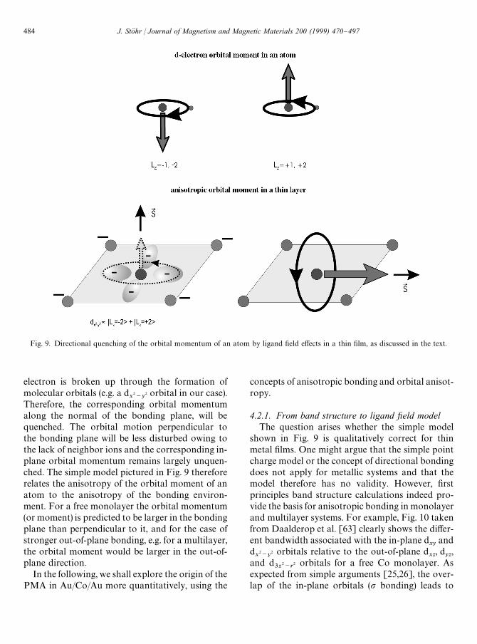
Fig. 9. Directional quenching of the orbital momentum of an atom by ligand "eld e!ects in a thin "lm, as discussed in the text.
electron is broken up through the formation ofmolecular orbitals (e.g. a d
x2~y
2 orbital in our case).Therefore, the corresponding orbital momentumalong the normal of the bonding plane, will bequenched. The orbital motion perpendicular tothe bonding plane will be less disturbed owing tothe lack of neighbor ions and the corresponding in-plane orbital momentum remains largely unquen-ched. The simple model pictured in Fig. 9 thereforerelates the anisotropy of the orbital moment of anatom to the anisotropy of the bonding environ-ment. For a free monolayer the orbital momentum(or moment) is predicted to be larger in the bondingplane than perpendicular to it, and for the case ofstronger out-of-plane bonding, e.g. for a multilayer,the orbital moment would be larger in the out-of-plane direction.
In the following, we shall explore the origin of thePMA in Au/Co/Au more quantitatively, using the
concepts of anisotropic bonding and orbital anisot-ropy.
4.2.1. From band structure to ligand xeld modelThe question arises whether the simple model
shown in Fig. 9 is qualitatively correct for thinmetal "lms. One might argue that the simple pointcharge model or the concept of directional bondingdoes not apply for metallic systems and that themodel therefore has no validity. However, "rstprinciples band structure calculations indeed pro-vide the basis for anisotropic bonding in monolayerand multilayer systems. For example, Fig. 10 takenfrom Daalderop et al. [63] clearly shows the di!er-ent bandwidth associated with the in-plane d
xyand
dx2~y
2 orbitals relative to the out-of-plane dxz
, dyz,
and d3z2~r
2 orbitals for a free Co monolayer. Asexpected from simple arguments [25,26], the over-lap of the in-plane orbitals (p bonding) leads to
484 J. Sto( hr / Journal of Magnetism and Magnetic Materials 200 (1999) 470}497

Fig. 10. Density of states and band structure of a free-standing Co(1 1 1) monolayer, calculated by Daalderop et al. [63]. (a) Majority-(dashed) and minority-spin (solid) orbital projected density of states for m"0 (d
3z2~r2), DmD"1 (d
xz, d
yz), and DmD"2 (d
x2~y
2 and dxy
).The &out-of-plane' orbitals (i.e. DmD"0, 1) have a narrower bandwidth than the &in-plane' orbitals (i.e., DmD"2). (b) Majority- (dashed)and minority-spin (solid) band structure of Co monolayer.
Fig. 11. Density of states for the d3z2~r
2 orbital in a Co mono-layer taken from Daalderop et al. [63] and for a Co monolayersandwiched between Au [structure Au(1 1 1)/Co(1 ML)/Au(2 ML)] taken from UD jfalussy et al. [83].
a larger bandwidth, relative to that for the lessoverlapping out-of-plane orbitals (p bonding). Incontrast, when the Co monolayer is sandwichedbetween Au layers, the strong out-of-plane bondingsigni"cantly increases the out-of-plane bandwidth.This is shown in Fig. 11, where the density of states(DOS) for the Co d
3z2~r2 orbital in a free Co mono-
layer [63], taken from Fig. 10, is compared to thatcalculated by UD jfalussy et al. [83] for the sameorbital in a Au/Co/Au sandwich. Figs. 10 and 11suggest that an anisotropic bonding model may beused for the description of the electronic structureof a free or sandwiched ultrathin magnetic layer. Inthe following we shall develop such a model for thecalculation of the orbital moment.
We can schematically represent the band struc-ture results for a free Co monolayer, shown in Fig.10 by the simple DOS model shown in Fig. 12. Herethe majority (spin down) band is assumed to be"lled, and we shall assume the minority band to behalf-"lled as obtained by the band structure resultsfor bulk and monolayer Co [26,63]. We shall dis-tinguish contributions from in-plane and out-of-plane d states. The in-plane d bandwidth is largerand the empty and "lled states have an averageseparation 2<
,. The narrower out-of-plane d band
exhibits an average separation between the emptyand "lled states of 2<
M. In our model, shown in Fig.
12, we further assume that the DOSs for the in-plane d
xyand d
x2~y
2 orbitals are the same. We makethe same assumption for the out-of-plane d
xz, d
yzorbitals and assume that the DOS for thed3z2~r
2 orbital has the same width as those for thedxz
and dyz
orbitals. This is reasonable according to
J. Sto( hr / Journal of Magnetism and Magnetic Materials 200 (1999) 470}497 485

Fig. 12. Schematic model for the density of minority spin statesfor a free Co monolayer. The half-"lled minority band may beseparated into contributions from in-plane and out-of-planed states, as shown. The in-plane bandwidth is larger because ofthe preferential in-plane bonds between the Co atoms and theempty and "lled states have an average separation 2<
,. The
narrower band of the out-of-plane d orbitals has an averageseparation between the empty and "lled states of 2<
M. The band
picture may be represented by a ligand "eld model where thein-plane and out-of-plane d orbitals are separated by 2<
,and
2<M, respectively, and an average is performed over two cases
(k1and k
2) with the empty and "lled d orbitals being exchanged,
as shown.
Fig. 10. The band picture may be represented bya ligand "eld model where the in-plane d
xyand
dx2~y
2 orbitals are separated by 2<,
and the out-of-plane d
xz, d
yz, and d
3z2~r2 orbitals are separated
by 2<M, as shown. In order to account for the
Brillouin zone averaged densities of states it is thennecessary to average over two cases, labelled k
1and
k2, where the empty and "lled d orbitals are ex-
changed. The wave vector re#ects the fact that thetwo cases may be thought of as band splittings attwo di!erent points k
1and k
2in the Brillouin zone.
See for example Fig. 2 in Wang et al. [26], wherethe order of the band states is inverted at the CM andMM points, respectively.
The model shown in Fig. 12 for a free Co mono-layer with <
,'<
Mcan be generalized to cases
with any <,/<
Mratio. For a sandwich of the form
X/Co/X the out-of-plane bandwidth is determinedby the overlap of the Co d orbitals with those of thesandwich layers X. Harrison (see chapter 20 in Ref.[95]) has tabulated interaction strengths betweendi!erent elements. If the in-plane Co}Co bondingstrength is normalized to 1.00, then the correspond-
ing out-of-plane Co}X bonding strength is 1.53,1.60, 1.38, 0.83 for X"Au, Pt, Pd, and Cu, respec-tively [26]. Hence we would predict that fora Au/Co/Au sandwich the out-of-plane bandwidthis larger than the in-plane one (i.e. <
M'<
,), in
good accord with the dramatic increase ind3z2~r
2 bandwidth shown in Fig. 11.
4.2.2. Orbital moment and spin}orbit energyanisotropy in ligand xeld model
By use of the simple ligand "eld concept we cannow calculate the anisotropy of the orbital momentfor di!erent bonding situations by use of perturba-tion theory [11,24,55]. The results for a Co MLcorresponding to <
,'<
Mare given in Fig. 13.
Here we have for simplicity assumed a level split-ting corresponding to the center of the BZ fora (1 0 0) monolayer. The in-plane and out-of-planesplittings of the non-perturbed states are
2<,"E
$xy!E
$x2~y2,D
(xy)(x2~y2), (12)
2<M"E
$yz!E
$3z2~r2,D
(yz)(3z2~r2), (13)
where D(n)(m)
denotes the energy di!erence betweenthe orbital states d
nand d
m. The results in Fig. 13
are obtained from Eq. (C.5) in Appendix C. We cannow apply the results in Fig. 13 to our modelshown in Fig. 12 and assuming a half-"lled spin-upband and a completely "lled spin-down band weobtain using the de"nition R"<
M/<
,,
m,0"
mkB
2<,A
3
R#
2
R#1B (14)
and
mM0"
mkB
2<,
4. (15)
Here m is the spin}orbit coupling constant whichfor Co has a value close to m"70 meV [21,84].Similarly, we obtain from Eqs. (C.6) and (C.8) inAppendix C for the magnetocrystalline anisotropyenergy if we neglect spin-#ip terms (*E
jj{"0),
SH,40T"!
m4k
B
m,0
(16)
and
SHM40T"!
m4k
B
mM0. (17)
486 J. Sto( hr / Journal of Magnetism and Magnetic Materials 200 (1999) 470}497

Fig. 13. Orbital momentum in a ligand "eld model with tetragonal or hexagonal symmetry. For simplicity we assume that the magneticexchange splitting is large and we consider only states of one spin. Band structure or ligand "eld e!ects result in d orbitals which arelinear combinations of functions Dl, m
-T (!2)m
-)#2). We show an energy level scheme corresponding to that at the center of the
BZ for a free Co monolayer with cubic (1 0 0) structure [26], where the in-plane splitting (2<@@) is larger than the out-of-plane splitting
(2<M). The pure d orbitals possess no orbital momentum. The inclusion of the spin}orbit interaction in lowest order perturbation theory
results in new states which have anisotropic orbital momenta (units +) as shown, where m (&0.07 eV for Co) is the spin}orbit couplingconstant and D
(i)(j)+1 eV is the energy separation (taken positive) between a higher energy state i and a lower state j. The indicated
orbital momenta for spin alignment SEz and SEx or y result from mixing of the spin-up states, only. Note that the total orbitalmomentum (sum) vanishes if all states are empty or full.
We obtain for the MCA energy,
*E40"
m4k
B
(m,0!mM
0)"
m28<
,A
3
R#
2
R#1!4B.
(18)
The anisotropies of the orbital moment ma0
andthe spin}orbit energy SHa
40T as a function of
R"<M/<
,according to Eqs. (14)}(17) are plotted
in Fig. 14. We see the preference for an in-planeeasy axis for <
,'<
M, revealed by the fact
m,0'mM
0, and for an out-of-plane easy axis for
<M'<
,. This result is in good accord with the
predictions of the simple model shown in Fig. 9.Our model also gives quantitative results surpris-
ingly similar to those obtained by means of "rstprinciples calculations. From Figs. 10 and 12 we see
that for a Co monolayer the in-plane bandwidth isabout 4<
,&4 eV and R"<
M/<
,"0.5. Using
the values<,"1 eV and R"<
M/<
,"0.5 eV and
m"0.07 eV/atom we obtain *E40"SHM
40T!
SH,40T"2.0]10~3 eV/atom, close to the value
*E40"1.5]10~3 eV/atom (using our sign conven-
tion) calculated by Daalderop et al. [63] for a freeCo monolayer. For a Au/Co/Au sandwich wewould also expect <
,"1 eV and using Harrison's
estimates of the in-plane (Co}Co) versus out-of-plane (Co}Au) bonding strengths we estimateR"<
M/<
,"1.5. With the values <
,"1 eV,
R"<M/<
,"1.5 and m"0.07 eV/atom we
obtain *E40"!0.7]10~3 eV/atom, close to
the value *E40"!1.0]10~3 eV/atom (using
our sign convention) calculated by UD jfalussy et al.[83].
J. Sto( hr / Journal of Magnetism and Magnetic Materials 200 (1999) 470}497 487

Fig. 14. (a) Spin}orbit energies as a function of R"<M/<
,based on the ligand "eld model in Fig. 12 with a half-"lled minority band
(2.5 electrons), for the case when the sample is magnetized in-plane (SH,T) and out-of-plane (SH
MT). (b) In-plane and out-of-plane
orbital moments as a function of R. The easy magnetization direction lies in-plane for R(1 (shaded region), as indicated by the icons inthe plot and out-of-plane for R'1.
Note that the simple picture presented by Fig. 14does not include the e!ect of the shape anisotropywhich favors an in-plane orientation. Thetransition from in-plane to out-of-plane easymagnetization is therefore actually shifted toR'1.
4.2.3. Majority band contribution to the orbitalmoment and the MCA
In the previous Section we focussed on the closecorrespondence of the orbital moment anisotropyand the spin}orbit energy anisotropy. As shownin Appendix C this correspondence only holdsunder two key assumptions: (i) that the spin-#ipterms involving matrix elements between minorityand majority bands are negligibly small and(ii) that the majority (spin-down) band is full. In thefollowing we shall look at the validity of theseassumptions.
Let us "rst consider the size of the spin-#ip termsusing our ligand "eld model under the assumptionthat the majority band is full. The spin}orbit energyanisotropy consists of two terms corresponding tocontributions from states with equal spin, *E
jj, and
unequal spin, *Ejj{
, as discussed in Appendix C. Wecan expand our model shown in Fig. 12 to alsoinclude the majority spin-down band, as shown in
Fig. 15. We then obtain,
*E40"*E
jj#*E
jj{
"
m24+2A+
n,m
DSd`nD¸
zDd`
mTD2!DSd`
nD¸
xDd`
mTD2
Dnm
#+i,m
DSd~i
D¸xDd`
mTD2!DSd~
iD¸
zDd`
mTD2
Dim
B, (19)
where the indices n and m label spin-up "lled andempty states, respectively, and i labels spin-down"lled states. Note D
imis negative. We obtain from
Eqs. (18) and (19),
*E40"
m4k
B
(m,0!mM
0)#*E
jj{, (20)
indicating that a direct proportionality between theorbital moment anisotropy and the spin}orbit en-ergy anisotropy holds only if the spin-#ip term*E
jj{is much smaller than the non-spin-#ip term
*Ejj"m(m,
0!mM
0)/4k
B.
De"ning A"D%9/<
,we obtain for the spin-#ip
term under the condition D%9'<
,, <
M,
*Ejj{"
m28<
,A!
1
A#R!1#
2
A!
1
A!R#1
!
6
A#2R!
2
A#R#1#
8
A#2B. (21)
488 J. Sto( hr / Journal of Magnetism and Magnetic Materials 200 (1999) 470}497

Fig. 15. Schematic density of states (boxes) and ligand "eld (horizontal energy levels in boxes) models for a free Co monolayer anda Au/Co/Au sandwich, based on bandstructure results [63] and our experimental results, respectively. The Co monolayer model issimilar to that shown in Fig. 12 but includes the majority bands. We also list the theoretical (Co monolayer) and experimentally(Au/Co/Au) determined in-plane and out-of-plane spin-dependent number of d holes.
5Wang et al. [25] have shown that for a "lled spin-up bandthe anisotropy of the spin-#ip term E
jj{is much smaller than that
of the term Ejj. This is seen from their expression for *E
jj{given
by our Eq. (27). This result is derived by replacing the denomin-ator in the spin-#ip terms in Eqs. (C.6) or Eq. (19) by theexchange splitting D
%9, and assuming that it is larger than the
crystal potential splitting. The spin-down states are then elimi-nated by summing over them.
In the limit of large exchange splittingD%9<<
,, <
Mthe various terms in Eq. (21) cancel
each other and the spin-#ip contribution to theanisotropy vanishes. The other limit is the caseD%9"0 (A"0). For A(1 the highest spin-down
states (both in- and out-of-plane) in Fig. 15 becomeunoccupied and no longer contribute to *E
jj{. We
obtain,
*Ejj{"
m28<
,A!
6
A#2R!
2
A#R#1#
8
A#2B.(22)
It is seen by comparison of Eqs. (18) and (22) thatthe spin-#ip contribution always has the oppositesign of the non-spin-#ip one and has a smallermagnitude. Hence in Eq. (20) the spin}orbit energyanisotropy is decreased relative to that calculatedfrom the orbital moment anisotropy. In the limitD%9"0 (A"0) the non-spin-#ip and spin-#ip con-
tributions are of equal size and cancel each other,*E
jj{"!*E
jj.
From Figs. 10 and 12 we see that for a Comonolayer the in-plane bandwidth is about
4<,&4 eV and the exchange splitting is about
D%9&2<
,&2eV. For a Au/Co/Au sandwich we
would expect the same values of D%9
and <,
andusing Harrison's estimates of the in-plane (Co}Co)versus out-of-plane (Co}Au) bonding strengths weestimate R"<
M/<
,"1.5. With these values we
calculate *Ejj{
/*Ejj"!0.25 from Eqs. (18) and
(21). Hence the spin-#ip term is predicted to bemuch smaller than the non-spin-#ip term and theeasy axis is therefore determined by *E
jj, i.e. by the
preferred direction of the orbital moment accord-ing to Eqs. (16) and (17). Similar conclusions aboutthe size of the spin-#ip terms have previously beenreached by Wang et al.5
J. Sto( hr / Journal of Magnetism and Magnetic Materials 200 (1999) 470}497 489

Let us now investigate our second assumption ofa "lled majority band. Again we shall use ourligand "eld model in Figs. 12 and 15 for an estimateof e!ects due to a partially "lled majority band andwe shall neglect spin-#ip terms. We shall assumethat the spin-up minority band is half-full (2.5 elec-trons and holes), as before, and assume that thehighest energy majority states are unoccupied. Inparticular, we shall consider the case <
M'<
,ap-
propriate for Au/Co/Au and assume that the high-est out-of-plane ligand "eld state is partlyunoccupied with a hole population 0(w(1. Ac-cording to Eq. (C.5) we can calculate the combinedorbital moment due to minority and majority statesthat would be measured in an XMCD experimentand obtain,
m,0!mM
0"
mkB
2<,C
3
R#
2
R#1!4
!wA3
R#
1
R#1BD. (23)
Note that the minority and majority contributionsenter with opposite sign (see Eq. (C.5)). Alterna-tively, we can calculate the spin}orbit energyanisotropy according to Eq. (C.7), ignoring allspin-#ip terms. Now the minority and majority con-tributions enter with the same sign and we obtain,
*E40"
m2
8<,C
3
R#
2
R#1!4#wA
3
R#
1
R#1BD.(24)
The spin}orbit energy anisotropy is therefore re-lated to the one calculated from the orbital momentanisotropy *E
m0"m(m,
0!mM
0)/4k
Bthat would be
measured by XMCD according to
*E40"*E
m0#*E
&*-(25)
with
*E&*-"
wm24<
,C
3
R#
1
R#1D. (26)
Since the "rst term in Eq. (25) is negative for<
M'<
,, the second, positive, term *E
&*-decreases
the spin}orbit energy anisotropy over the valuecalculated from the orbital moment anisotropy,similar to the term *E
jj{in Eq. (20).
For R"<M/<
,"1.5 we obtain *E
&*-/
*Em0"!4w/(1#2w). This is a strongly varying
function of w but for a realistic value of w"0.1 weobtain *E
&*-/*E
m0"!1
3indicating again that the
spin}orbit energy anisotropy is dominated by theorbital moment anisotropy of the minority band.
5. XMCD results and theoretical models
5.1. Anisotropy of charge and spin density
Our experimental results for Au/Co/Au in Fig. 6cshow that the number of 3d holes per atoms isisotropic (NM"N,) within experimental error. TheCo charge density in the atomic volume is thereforepredicted to be nearly spherical. In contrast, theexperimental results in Fig. 8 reveal a signi"cantanisotropy in the spin density ma
D. At the thin end of
the wedge (3 ML Co) we obtain m4"1.43 l
B,
mMD"0.15 l
Band m,
D"!0.075 l
Bfrom Fig. 8
which yields mM4"0.27 l
Band m,
4"0.31 l
Bac-
cording to Eq. (6). In 3d metals the anisotropy inthe spin density is mainly induced by the bondinganisotropy, i.e. by the anisotropic charge distribu-tion in the unit cell because of the small spin}orbitcoupling. If the majority band is completely full thecharge and spin distributions are identical. Ourresults therefore reveal that the majority band isnot completely "lled. Combining our charge andspin results we can obtain the in-plane and out-of-plane number of majority and minority holes. Us-ing the experimental values for 3 ML Co thicknessN,"N,
t#N,
s"NM"NM
t#NM
s"2.5/5"0.50
and m,4"(N,
t!N,
s) l
B"0.31 l
Band mM
4"
(NMt!NM
s) l
B"0.27 l
Bwe obtain N,
t"0.41,
N,s"0.09, NM
t"0.39 and NM
s"0.11. The results
are graphically illustrated in Fig. 15 together withthose for a free Co monolayer as calculated byDaalderop [63]. The various anisotropies forAu/Co/Au are found to be opposite to those fora free Co monolayer, in support of the discussion inSection 4.2.1.
Our "nding of a signi"cant number of majorityholes has implications for the contribution of themajority band to the orbital moment and spin}orbit energy anisotropies as discussed in Section4.2.3. The holes in the majority band give rise to
490 J. Sto( hr / Journal of Magnetism and Magnetic Materials 200 (1999) 470}497

a term *E&*-
(Eq. (26)) and cause a break down ofthe simple proportionality of the spin}orbit energyanisotropy with the orbital moment anisotropy ac-cording to Eq. (25). This will be discussed in moredetail in Section 5.2 below.
There is also an interesting connection of thecharge and spin density anisotropies with the spin-#ip terms discussed in Section 4.2.3. Wang et al.[25] (see footnote 5), showed that in the limit oflarge exchange splitting and a "lled majority bandthe quadrupolar charge density, which in thismodel is identical to the spin density, gives rise toa magnetic anisotropy contribution which is pro-portional to the spin-#ip term *E
jj{discussed in
Section 4.2.3. Using our notation the result ofWang et al. is given by (see footenote 5)
*Ejj{"
!m28+2D
%9
+n,k,E
S/`n(k, E)D3¸2
z!¸2D/`
n(k, E)T
"
!m2
8+2SQL
zzT
D%9
"
!21m216
SQzz
TD%9
. (27)
In this case the anisotropy depends only on thequadrupole moment (see Appendix A) of the occu-pied states in the spin-up minority band and isinversely proportional to the exchange splitting(note that the "lled subband has SQL
zzT"0). In this
model our result of a vanishing small white lineanisotropy for Au/Co/Au for all Co thicknesses, i.e.Na
Q"7/8SQaaT&0, would predict a negligibly
small contribution to the magnetic anisotropy dueto the quadrupolar charge ("spin) anisotropy.
The result of Wang et al. was extended by DuK rrand van der Laan [42,85] to the general case ofminority as well as majority spin contributions, thesituation encountered for our Au/Co/Au structure.It was proposed that, in general, the intra-atomicmagnetic dipole term plays a role for the MCAthrough a term S )T that couples the atomic spinwith the dipole operator. Since for transition metalsthe dipole operator is approximately given by¹a"(2/21+2)(3¸2a!¸2)S
z8(see Appendices A and
B), a magnetic anisotropy results from thespin}orbit coupling, and the S )T term is related tothe spin-#ip anisotropy energy *E
jj{discussed in
Section 4.2.3. Estimates of the spin-#ip anisotropyenergy from our measured anisotropy of the dipolemoments ma
D"!7S¹aTk
B/+ (see Fig. 8) again pre-
dict a small spin-#ip contribution to the spin}orbitanisotropy.
The contribution of the intra-atomic dipole mo-ment to the magnetic anisotropy suggested byWang et al. and by DuK rr and van der Laan is basedon spin}orbit coupling. Since for 3d metals theintra-atomic magnetic dipole term is mainly deter-mined by the anisotropy of the lattice there is alsoa magnetostatic contribution to the magnetic an-isotropy, as discussed in Section 4.1. This is due toa quadrupole term in the magnetostatic energy. Wemay estimate the size of this anisotropy energyfrom the Au/Co/Au data at a Co thickness of 3 ML(Fig. 8). We use the experimentally determinedquadrupole term in the spin density mM
D/2"m,
D"
0.075 lB
and the spin moment m4"1.5 l
Bto esti-
mate the size of the quadrupole induced magnetos-tatic anisotropy relative to the monopole term tobe mM
D/2m
4"0.05 (see footnote 3). Hence we con-
clude that, in practice, the intra-atomic magneticdipole moment plays a negligible role for the mag-netic anisotropy.
5.2. Anisotropy of orbital moment
The anisotropy of the orbital moment shown inFig. 7c qualitatively shows the same thickness de-pendence as the energy anisotropy shown in Fig. 4cobtained from the Kerr measurements. We can usethe XMCD values for mM
0!m,
0to calculate the
corresponding spin}orbit energy anisotropy by useof the spin}orbit coupling constant for Co whichwe assume to have the value m"70 meV [21,84].Because of the problems associated with extrapola-tions we shall simply compare the XMCD andKerr results obtained at a Co thickness of 3 ML.The XMCD value mM
0!m,
0"(0.22$0.05) l
B/
atom then yields the anisotropy energy*E
40"m(m,
0!mM
0)/4"!3.8]10~3 eV/atom.
Here we have used Eq. (18), i.e. neglected the spin-#ip terms *E
jj{in Eq. (20) and assumed a "lled
majority band so that the term *E&*-
in Eq. (25) isnegligible. This value is larger than the Kerr result*E
40"!2.55 MJ/m3"!1.8]10~4 eV/atom
(Fig. 4c) by a factor of about 20.The anisotropy energy calculated from the or-
bital moment anisotropy using the proportionalityfactor C"m/4 (see Eqs. (11) and (18)) obtained by
J. Sto( hr / Journal of Magnetism and Magnetic Materials 200 (1999) 470}497 491

perturbation theory is therefore signi"cantly in er-ror. Comparing experimental Kerr and XMCDvalues for 3 ML Co we obtain the proportionalityfactor C in Eq. (11) to be C"0.8]10~3 eV/l
Bwhich is the same as that obtained for Co/Pd multi-layers by DuK rr et al [86]. A similar value,C"0.68]10~3 eV/l
B, has recently been obtained
from ferromagnetic resonance data for the BCCFe
2/V
5(0 0 1) superlattice system [87]. On the
theory side larger C values have been obtained thatare in closer agreement with the perturbation valuem/4"1.8]10~2 eV/l
B. Using a fully relativistic
spin polarized theory for Au(1 1 1)/Co(1 ML)/Au(R), UD jfalussy et al. [83] obtained C"5]10~2 eV/l
B. DuK rr et al. [37] obtained 1.6]
10~2 eV/lB
from electronic structure calculationsfor face centered tetragonal (FCT) Ni and Co andHjortstam et al. [88] obtained approximately2.6]10~2 eV/l
Bfor FCT Ni, although the rela-
tionship between *E40
and *m0
was found to beonly approximately linear as a function of the FCTc/a ratio.
The reason for the discrepancy between theMCA energy calculated from the XMCD orbitalmoment anisotropy and that obtained from Kerrmeasurements remains to be explained. A possiblesource for the discrepancy is the majority bandcontribution discussed in Section 4.2.3. Eqs. (20)and (25) may be written in the general form*E
40"*E
m0[1#*E
.!+/*E
.*/] where the term
*E.!+
represents either the spin-#ip or the directmajority band contribution. In order to obtain theKerr value *E
40"!1.8]10~4 eV/atom for
3 ML Co in Au/Co/Au the XMCD value*E
m0"!3.8]10~3 eV/atom needs to be correc-
ted by [1#*E.!+
/*E.*/
]"0.05. This would re-quire an almost equal contribution *E
.!+"
!0.95*E.*/
of the majority and minority bands tothe spin}orbit anisotropy. Our estimates in Section4.2.3 and Section 5.1 of the majority band contribu-tions to the MCA, yielding D*E
.!+/*E
.*/D(0.4,
make it very unlikely that the discrepancy can beentirely explained by either the spin-#ip terms or byincomplete "lling of the majority band.
A possible explanation is provided by the factthat XMCD is a local, element speci"c, probe. Inour case the determined orbital moments are thoseof the Co atoms alone. In contrast, the total MCA
and the Kerr measurements contain contributionsfrom magnetically polarized Au atoms at the inter-faces. Interfacial hybridization between Co and Custates in Co/Co multilayers has been observed ex-perimentally and theoretically [89] and it is re-sponsible for an appreciable magnetic moment onCu interface atoms [31]. Similar e!ects are ex-pected for Co/Au sandwiches. As revealed by Figs.11 and 15 the hybridization of Co and Au atoms atthe interface leads to an increase in bandwidth. TheCo derived minority d states, which are mostlyresponsible for the orbital moment, are concen-trated in the region !3 to #1 eV relative to theFermi level (see Fig. 10) while the Au d states lie inthe !7.5 to !2 eV range [90]. According to Eq.(18) the MCA energy and orbital moment anisot-ropy are inversely proportional to the average sep-aration (<
,or <
M) between the "lled and empty
minority states. If all Co}Au hybridized states areconsidered the e!ective < is considerably largerthan for the Co states only. The reduced momentassociated with the Au derived states may be o!setby the larger size of the spin}orbit coupling con-stant (m
A6/m
C0&7) [91]. Qualitatively, one would
therefore expect the MCA determined by XMCD(Co states only) to be signi"cantly larger than thatobtained by Kerr measurements (Co}Au states).Clearly, more theoretical and experimental work isneeded to explore the quantitative correlation be-tween the orbital moment anisotropy measured byXMCD and the true spin}orbit energy anisotropy.
Despite the quantitative discrepancy of theXMCD and Kerr results the orbital moment an-isotropy obtained from XMCD provides experi-mental veri"cation of a simple picture for themicroscopic origin of the MCA shown in Fig. 9. Atthe thick end of the wedge the orbital magneticmoment is nearly isotropic. Here, the overall in-plane anisotropy of the sample is simply due to themacroscopic shape anisotropy. With decreasingsample thickness, the average symmetry of the Coatoms becomes increasingly anisotropic. At thethin end of the wedge the anisotropy of the orbitalmoment has become so large that it has a strongpreference for a perpendicular orientation. Nowthere are two opposing forces acting on the spinmoment. The dipolar "eld wants to rotate it in-plane and the spin}orbit coupling wants to rotate it
492 J. Sto( hr / Journal of Magnetism and Magnetic Materials 200 (1999) 470}497
parallel to the out-of-plane orbital moment(Hund's third rule). The easy axis is determined bywhich of the two forces is stronger, i.e. whether thedipolar energy is smaller or larger than the anisot-ropy of the spin}orbit energy. Clearly, at the thinedge of the wedge the anisotropy energy associatedwith the spin}orbit interaction exceeds the value ofthe shape anisotropy and we have the interestingsituation that the small orbital moment redirectsthe larger spin moment into a perpendicular align-ment.
6. Summary and conclusions
The present paper discusses the use of XMCDspectroscopy to explore the microscopic origin ofelectronic and magnetic anisotropies in transitionmetal thin "lms, in particular, for Co in a Au/Co-staircase/Au sample. XMCD spectroscopy isshown to provide detailed information on the an-isotropy of the atomic charge and spin in theatomic cell. For thin "lms with uniaxial anisotropyaround the surface normal, angle-dependentXMCD measurements in strong magnetic "elds areshown to quantitatively determine the in-plane andout-of-plane spin-dependent d-band occupations.These results complement those obtained from "rstprinciples electronic structure calculations.
The anisotropy of the orbital magnetic momentis shown to be especially important because of itsclose link to the magnetocrystalline anisotropy.A simple picture based on anisotropic bonding isdeveloped that allows one to visualize the preferreddirection of the orbital moment. The pictureis based on the well-known textbook conceptof orbital moment quenching by a ligand "eld.The connection is made between this simple pictureand the concepts and results of electronic struc-ture calculations. Model calculations that linkligand "eld and band structure concepts are carriedout to explore the link between orbital momentanisotropy and spin}orbit energy anisotropy.They are found to have remarkably predictive ca-pabilities.
XMCD results for Au/Co/Au are discussed interms of the presented theoretical model. Our re-sults lead to a particularly illustrative picture for
the origin of the magnetocrystalline anisotropybased on the preferred direction of the orbitalmoment.
Acknowledgements
This work was carried out in part at SSRL whichis operated by the Department of Energy, Divisionof Chemical Sciences. I would like to thank mycollaborators who were involved in the originalwork reviewed here, especially Dieter Weller, ReikoNakajima, Mahesh Samant, and Claude Chappert.I am also indebted to Balazs Ujfalussy for provid-ing unpublished theoretical results for Au/Co/Au,to Olle Eriksson for elucidating discussions aboutorbital polarization and hybridization e!ects, andto Patrick Bruno for pointing out references toearly work on orbital anisotropy.
Appendix A. Charge density term and quadrupoleoperator
The terms N and NaQ
in the charge sum rulere#ect the monopole and quadrupole contributionsof the charge distribution in the atomic sphere.Na
Qcan be expressed in terms of the quadrupole
operator of the charge, Qab"dab!3r( ar( b) Qab isa second rank tensor with the symmetry propertiesQab"Qba and +aQaa"0. The tensor elementsQab can be expressed as a linear combination of thewell-known spherical harmonics >m
l(h, /) with
l"2 and !2)m)2. For example, the quadru-pole moment of the charge is given by SQ
zzT"
S1!3 cos2 hT"!J16p/5S>02T and it is related
to the quadrupole moment of the angular mo-mentum SQL
zzT"S3¸2
z!¸2T"(21+2/2)SQ
zzT.
Let /n(k, E)"+
i,jaji,n
(k, E)disj denote a band
state with spin functions sj ( j"$). We thenobtain SQaaT"+
n,k,ES/
n(k, E)DQaaD/n
(k, E)T"+
iSd
iDQaaDdi
T+n,k,E,j
Daji,n
(k, E)D2. The last sum is justthe d orbital projected number of electrons (orholes) Ni"+
n,k,E,jDaj
i,n(k, E)D2 and the matrix ele-
ments Qia"SdiDQaaDdi
T have been tabulated byStoK hr and KoK nig [34]. This gives Na
Q"
(7/B)+iQiaNi"(7/B)SQaaT. Here B"!4 for
J. Sto( hr / Journal of Magnetism and Magnetic Materials 200 (1999) 470}497 493

6For higher than D2)
symmetry all cross terms SdiDQaaDdj
T inthe crystal wave functions vanish. This holds even in the pres-ence of s}o coupling since it does not mix the two e
'orbitals
which give rise to a cross term.
linearly polarized light (electric "eld vector EEa),and B"8 for circularly or plane polarized light(X-ray wave vector kEa, Eok) [41]. Note that thequantities Na
Q"(7/4)SQiaT (a"x, y, z) correspond
to the diagonal components of a normalized quad-rupole tensor of the charge (holes), also called ori-entation matrix or Saupe matrix [92] and they areidentical to the quadrupole terms in the multipoleexpansion of the charge [93].
Appendix B. Spin density term and magnetic dipoleoperator
The terms m4and ma
Din the spin sum rule re#ect
the monopole and quadrupole contributions of thespin distribution in the atomic sphere. In general,ma
Dis de"ned as the expectation value of the intra-
atomic magnetic dipole operator T"S!3r( (r( ) S),generated by the valence electrons [39], accordingto Ref. [55] ma
D"!7S¹aTk
B/+. In general, one
can write ¹a"+bQabSb, indicating the coupledcharge (Q) and spin (S) components of T. Since thequadrupole operator of the charge is related to thequadrupole operator of the angular momentum, asdiscussed in Appendix A, ¹a may also be written asa coupled operator involving the spin and thesquare of the angular momentum.
If we choose the spin quantization axis z8 alongthe magnetization direction then the components(S
x, S
y, S
z) of the spin S in the crystal frame are
related to the components (Sx8, S
y8, S
x8) in the rotated
spin frame (x8 , y8 , z8 ) by Sx"S
x8cos /I cos hI !
Sy8sin /I #S
z8cos /I sin hI , S
y"S
x8sin /I cos hI #S
y8cos /I #S
z8sin /I sin hI , and S
z"!S
x8sin hI #
Sz8cos hI and the magnetic dipole operator takes the
following form for k, H%95
Ex, y or z
k, H%95
Ex: ¹x"Q
xxSz8#Q
xySy8!Q
xzSx8, (B.1)
k, H%95
Ey: ¹y"!Q
yxSy8#Q
yySz8!Q
yzSx8, (B.2)
k, H%95
Ez: ¹z"Q
zxSx8#Q
zySy8#Q
zzSz8. (B.3)
For the 3d transition metals the spin}orbit inter-action is much smaller than the exchange interac-tion and the crystal potential. In this case theexpectation values of ¹a are only slightly a!ected
when spin}orbit perturbed band states are usedinstead of band states without inclusion of thespin}orbit interaction. That means we can neglectthe e!ect of spin}orbit coupling in evaluating thematrix elements in Eqs. (B.1)}(B.3) and hence allterms containing the spin-#ip operators S
x8and
Sy8do not contribute. We can therefore replace the
general operator ¹a"+bQabSb simply by ¹a"QaaSz8
. Let /n(k, E)"+
i,jaji,n
(k, E)disj denote a band
state with spin functions sj ( j"$). We thenobtain6 S¹aT"+
n,k,ES/
n(k, E)DQaaSz8
D/n(k, E)T"
+iSd
iDQaaDdiT+
n,k,E,jDaj
i,n(k, E)D2SsjDS
z8DsjT. The last
sum contains just the d orbital projected spin mo-menta SSi
z8T"!(+/2k
B)+
imi
4so that we obtain
S¹aT"!(+/2kB)+
iQiami
4, re#ecting the decoupled
nature of charge and spin. This givesma
D"(7/2)+
iQiami
4which leads to Eq. (6).
There is a formal relationship between the intra-atomic dipole moment T"+
jsLj!3r(
j(r(j) s(
j) gener-
ated by the valence electrons, and the inter-atomicdipole "eld H"(mk
0/4p)+
j(SK
j!3r(
j(r(j) SK
j))/r3
jcre-
ated at a given atomic site (placed at the origin) byall other moments mSK
jin the sample at positions
rjr(j. In particular, the magnetic dipole}dipole inter-
action given by Eq. (8) can be viewed as the energyof a dipole moment mSK at the origin in the "eld ofall the other dipoles, according to E
$*1~$*1"
mSK )H. The intra-atomic dipole moment T contrib-utes to the magnetic anisotropy in higher orderthrough a quadrupole term (see footnote 3) in themagnetostatic dipole}dipole interaction as dis-cussed in Section 4.1. The quantities ma
D/2 corre-
spond to the quadrupole terms in the multipoleexpansion of the magnetic moment in the unit cell[93] (see footnote 3).
Appendix C. The spin}orbit interaction
Here we brie#y discuss the calculation of matrixelements of the anisotropic spin}orbit interactionand the orbital moment using perturbation theory.
494 J. Sto( hr / Journal of Magnetism and Magnetic Materials 200 (1999) 470}497

The spin}orbit (s}o) interaction within the dshell
H40"mL )S"m(¸
xSx#¸
ySy#¸
zSz), (C.1)
has the e!ect of mixing di!erent d orbitals and thespin-up and spin-down states. If we choose thespin quantization axis z8 along the magnetizationdirection then the components (S
x, S
y, S
z) of
the spin S in the crystal frame can be expressed interms of the components (S
x8, S
y8, S
x8) in the
rotated spin frame (x8 , y8 , z8 ) as discussed in AppendixB. This gives the following expressions forH
%95, z8 Ex, y or z
H%95
Ex: Hx40"m(¸
xSz8#¸
ySy8!¸
zSx8), (C.2)
H%95
Ey: Hy40"m(!¸
xSy8#¸
ySz8!¸
zSx8), (C.3)
H%95
Ez: Hz40"m(¸
xSx8#¸
ySy8#¸
zSz8). (C.4)
The angle-dependent orbital momentma
0"!S¸aTk
B/+ is calculated by use of the sec-
ond-order perturbation theory expression [11]
S¸aT"2m+2
+k,n,m,j
DS/jn(k)D¸aD/j
m(k)TD2
Dnm
SsjDSz8DsjT
"S¸`a T!S¸~a T, (C.5)
where the sum extends over "lled states n andempty states m within the spin-up and spin-downmanifolds (index j) and /j
n(k) denotes a zeroth-order
band state associated with spin function sj, whereSsBDS
z8TDsBT"$1/2. Matrix elements Sd
nD¸aDdmT
are given by Ballhausen (see p. 70 in Ref. [96]).Note that the coupling between "lled pairs of statesor empty pairs of states does not need to be con-sidered since the spin}orbit induced terms canceleach other for any pair. Also, to "rst-order ma
0does
not depend on the mixing of spin-up and spin-down states by the spin}orbit interaction, since therelevant matrix elements Sd
ns`D¸aDdm
s~T"0.Thus there are no spin-#ip contributions tothe orbital moment. According to Eq. (C.5)the orbital momentum is the sum of contributionsfrom all "lled states in the spin-up and spin-downsubbands. If a subband is "lled its contributionvanishes.
The angle-dependent spin}orbit energy is givenby the second-order expression
SHa40T"
m2
4+2+
k,n,m,j
DS/jn(k)D¸aD/j
m(k)TD2
Dnm
# +k,n,l,j,j{
DS/jn(k)DHa
40D/j{
l(k)TD2
Dnl
"Eajj#Ea
jj{,
(C.6)
where the terms Eajj
and Eajj{
represent the contribu-tions from states of the same and opposite spin,respectively, and the sums extend over "lled states(n, j) and empty states (m, j) and (l, j@).
It is seen that for Eajj{"0 we obtain
SHa40T"Ea
jj"
m4+
(S¸`a T#S¸~a T), (C.7)
showing the direct correlation between the orbitalmoments of the spin-up and spin-down manifoldsand the spin}orbit energy. Note that the contribu-tions of the spin-down states, S¸~a T, enter withopposite signs in the expressions for the orbitalmoment (Eq. (C.5)) and the spin}orbit energy (Eq.(C.7)). In general, we therefore obtain a direct pro-portionality between the orbital moment and thespin}orbit energy only if S¸~a T"0, i.e. if the spin-down band is full. In the limit of a vanishing ex-change splitting the orbital moment vanishes(S¸`a T"S¸~a T), and so does the spin}orbit energy(Ea
jj"!Ea
jj{).
With the sign convention of Eq. (11) and footnote4 the magnetocrystalline anisotropy energy is givenby
*E40"SHz
40T!SHx
40T"SHM
40T!SH,
40T. (C.8)
References
[1] A.J. Freeman, R. Wu, J. Magn. Magn. Mater. 100 (1991)497.
[2] O. Eriksson et al., Solid State Commun. 78 (1991) 801.[3] O. Eriksson et al., Phys. Rev. B 45 (1992) 2868.[4] Y. Wu, J. StoK hr, B.D. Hermsmeier, M.G. Samant, D. Wel-
ler, Phys. Rev. Lett. 69 (1992) 2307.[5] R. Wu, D. Wang, A.J. Freeman, Phys. Rev. Lett. 71 (1993)
3581.[6] R. Wu, A.J. Freeman, Phys. Rev. Lett. 73 (1994) 1994.[7] D. Weller, Y. Wu, J. StoK hr, M.G. Samant, B.D. Her-
msmeier, C. Chappert, Phys. Rev. B 49 (1994) 12888.
J. Sto( hr / Journal of Magnetism and Magnetic Materials 200 (1999) 470}497 495
[8] M. Tischer, O. Hjortstam, D. Arvanitis, J.H. Dunn, F.May, K. Baberschke, J. Trygg, J.M. Wills, B. Johansson, O.Eriksson, Phys. Rev. Lett. 75 (1995) 1602.
[9] N. Nakajima, T. Koide, T. Shidara, H. Miyauchi, H.Fakutani, A. Fujimori, K. Iio, T. Katayama, M. NyH vlt, Y.Suzuki, Phys. Rev. Lett. 81 (1998) 5229.
[10] H.A. DuK rr, S.S. Dhesi, E. Dudzik, D. Knabben, G. van derLaan, J.B. Goedkoop, F.U. Hillebrecht, Phys. Rev. B 59(1999) R701.
[11] P. Bruno, Phys. Rev. B 39 (1989) 865.[12] U. Gradmann, J. MuK ller, Phys. Stat. Sol. 27 (1968) 313.[13] U. Gradmann, Appl. Phys. 3 (1974) 161.[14] F.J.A. den Broeder, W. Hoving, P.J.H. Bloemen, J. Magn.
Magn. Mater. 93 (1991) 562.[15] G.H.O. Daalderop, P.J. Kelly, M.F.H. Schuurmans, Phys.
Rev. Lett. 68 (1992) 682.[16] K. Baberschke, Appl. Phys. A 62 (1996) 417.[17] B.M. Lairson, M.R. Visokay, R. Sinclair, B.M. Clemens,
Appl. Phys. Lett. 62 (1993) 639.[18] B. Zhang, W.A. So!a, Scripta Metall. Mater. 30 (1994) 683.[19] A. Cebollada, D. Weller, J. Sticht, G.R. Harp, R.F.C.
Farrow, R.F. Marks, R. Savoy, J.C. Scott, Phys. Rev. B 50(1994) 3419.
[20] T. Klemmer, D. Hoydick, H. Okumura, B. Zhang, W.A.So!a, Scripta Metall. Mater. 33 (1995) 1793.
[21] G.H.O. Daalderop, P.J. Kelly, M.F.H. Schuurmans, Phys.Rev. B 41 (1990) 11919.
[22] J. Trygg, B. Johansson, O. Eriksson, J.M. Wills, Phys. Rev.Lett. 75 (1995) 2871.
[23] J.H. Van Vleck, Phys. Rev. 52 (1937) 1178.[24] P. Bruno, in: Magnetismus von FestkoK rpern und Grenz-
#aK chen, KFA JuK lich, JuK lich, 1993, p. 24.1.[25] D. Wang, R. Wu, A.J. Freeman, Phys. Rev. B 47 (1993)
14932.[26] D. Wang, R. Wu, A.J. Freeman, J. Magn. Magn. Mater.
129 (1994) 237.[27] G. SchuK tz, W. Wagner, W. Wilhelm, P. Kienle, R. Zeller,
R. Frahm, G. Materlik, Phys. Rev. Lett. 58 (1987) 737.[28] G. SchuK tz, R. Wienke, W. Wilhelm, W. Wagner, P. Kienle,
R. Zeller, R. Frahm, Z. Phys. B 75 (1989) 495.[29] C.T. Chen, F. Sette, Y. Ma, S. Modesti, Phys. Rev. B 42
(1990) 7262.[30] W.L. O'Brien, B.P. Tonner, Phys. Rev. B 50 (1994) 12672.[31] M.G. Samant, J. StoK hr, S.S.P. Parkin, G.A. Held, B.D.
Hermsmeier, F. Herman, M. van Schilfgaarde, L.-C. Duda,D.C. Mancini, N. Wassdahl, R. Nakajima, Phys. Rev. Lett.72 (1994) 1112.
[32] W.L. O'Brien, B.P. Tonner, G.R. Harp, S.S.P. Parkin,J. Appl. Phys. 76 (1994) 6462.
[33] J. Hunter Dunn, D. Arvanitis, N. Ma> rtensson, M. Tischer,F. May, M. Russo, K. Baberschke, J. Phys.: Condens.Matter 7 (1995) 1111.
[34] S. Pizzini, A. Fontaine, C. Giorgetti, E. Dartyge, J.F. Bobo,M. Piecuch, F. Baudelet, Phys. Rev. Lett. 74 (1995) 1470.
[35] D. Weller, J. StoK hr, R. Nakajima, A. Carl, M.G. Samant, C.Chappert, R. MeH gy, P. Beauvillain, P. Veillet, G. Held,Phys. Rev. Lett. 75 (1995) 3752.
[36] G.R. Harp, S.S.P. Parkin, W.L. O'Brien, B.P. Tonner,Phys. Rev. B 51 (1995) 12037.
[37] H.A. DuK rr, G.Y. Guo, G. van der Laan, J. Lee, G. Lauho!,J.A.C. Bland, Science 213 (1997) 277.
[38] B.T. Thole, P. Carra, F. Sette, G. van der Laan, Phys. Rev.Lett. 68 (1992) 1943.
[39] P. Carra, B.T. Thole, M. Altarelli, X. Wang, Phys. Rev.Lett. 70 (1993) 694.
[40] P. Carra, H. KoK nig, B.T. Thole, M. Altarelli, Physica B 192(1993) 182.
[41] J. StoK hr, H. KoK nig, Phys. Rev. Lett. 75 (1995) 3748.[42] H. DuK rr, G. van der Laan, Phys. Rev. B 54 (1996) 760.[43] G. van der Laan, J. Phys.: Condens. Matter 9 (1997)
L259.[44] G. van der Laan, Phys. Rev. B 57 (1998) 5250.[45] G. van der Laan, Phys. Rev. B 57 (1998) 112.[46] B.D. Cullity, Introduction to Magnetic Materials, Ad-
dison-Wesley, Reading, MA, 1972.[47] F. Sette, C.T. Chen, Y. Ma, S. Modesti, N.V. Smith, in: S.S.
Hasnain (Ed.), X-Ray Absorption Fine Structure, EllisHorwood Limited, Chichester, England, 1991, p. 96.
[48] Y.U. Idzerda, L.H. Tjeng, H.-J. Lin, C.J. Gutierrez, G.Meigs, C.T. Chen, Phys. Rev. B 48 (1993) 4144.
[49] J. StoK hr, Y. Wu, B.D. Hermsmeier, M.G. Samant, G.R.Harp, S. Koranda, D. Dunham, B.P. Tonner, Science 259(1993) 658.
[50] A. Aspelmeier, M. Tischer, M. Farle, M. Russo, K.Baberschke, D. Arvanitis, J. Magn. Magn. Mater. 146(1995) 256.
[51] C.T. Chen, Y.U. Idzerda, H. Lin, G. Meigs, A. Chaiken,G.A. Prinz, G.H. Ho, Phys. Rev. B 48 (1993) 642.
[52] L.H. Tjeng, Y.U. Idzerda, P. Rudolf, F. Sette, C.T. Chen,J. Magn. Magn. Mater. 109 (1992) 288.
[53] W.L. O'Brien, B.P. Tonner, Phys. Rev. B 52 (1995) 1.[54] J. StoK hr, Y. Wu, in: A.S. Schlachter, F.J. Wuilleumier
(Eds.), New Directions in Research with Third-GenerationSoft X-Ray Synchrotron Radiation Sources, Kluwer Aca-demic Publishers, Netherlands, 1994, p. 221.
[55] J. StoK hr, J. Electron. Spectrosc. Relat. Phenom. 75 (1995)253.
[56] J. StoK hr, R. Nakajima, IBM J. Res. Develop. 42 (1998) 73.[57] O. Eriksson, B. Johansson, R.C. Albers, A.M. Boring,
M.S.S. Brooks, Phys. Rev. B 42 (1990) 2707.[58] P. SoK derlind, O. Eriksson, B. Johansson, R.C. Albers, A.M.
Boring, Phys. Rev. B 45 (1992) 12911.[59] H. Ebert, J. StoK hr, S.S.P. Parkin, M. Samant, A. Nilsson,
Phys. Rev. B 53 (1996) 16067.[60] R.P. Feynman, R.B. Leighton, M. Sands, The Feynman
Lectures on Physics, Vol. I, Part 2, Addison-Wesley, Read-ing, MA, 1964.
[61] J.C. Slater, G.F. Koster, Phys. Rev. 94 (1954) 1498.[62] D.A. Papaconstantopoulos, Handbook of the Band Struc-
ture of Elemental Solids, Plenum, New York, 1986.[63] G.H.O. Daalderop, P.J. Kelly, M.F.H. Schuurmans, Phys.
Rev. B 50 (1994) 9989.[64] P.F. Carcia, A.D. Meinholdt, A. Suna, Appl. Phys. Lett. 47
(1985) 178.
496 J. Sto( hr / Journal of Magnetism and Magnetic Materials 200 (1999) 470}497
[65] J.E. Hurst Jr., W.J. Kozlovsky, Jpn. J. Appl. Phys. 32 (1993)5301.
[66] G.H.O. Daalderop, P.J. Kelly, M.F.H. Schuurmans, Phys.Rev. B 44 (1991) 12054.
[67] D. Renard, G. Nihoul, Philos. Mag. B 55 (1987) 75.[68] C. Cesari et al., J. Magn. Magn. Mater. 78 (1989) 296.[69] J. Ferre et al., Appl. Phys. Lett. 56 (1990) 1588.[70] V. Grolier et al., Phys. Rev. Lett. 71 (1993) 3023.[71] R. Nakajima, J. StoK hr, I. Idzerda, Phys. Rev. B 59 (1999)
6421.[72] R. Nakajima, Ph. D. dissertation, Standford University,
1998, unpublished.[73] H.J.G. Draaisma, W.J.M. de Jonge, J. Appl. Phys. 64
(1988) 3610.[74] O. Eriksson, M.S.S. Brooks, B. Johansson, Phys. Rev. B 41
(1990) 7311.[75] P. Strange, H. Ebert, J.B. Staunton, B.L. Gyor!y, J. Phys.
C 1 (1989) 3947.[76] L. Szunyogh, B. UD jfalussy, P. Weinberger, Phys. Rev. B 51
(1995) 9552.[77] G. Aubert, J. Appl. Phys. 39 (1968) 504.[78] J.P. Rebouillat, IEEE Magn. 8 (1972) 630.[79] P. Escudier, Ann. Phys. (Paris) 9 (1975) 125.[80] R. Pauthenet, J. Appl. Phys. 53 (1982) 8187.[81] F. Ducastelle, F. Cyrot-Lackmann, J. Phys. (Paris)
C 1 (1971) 537.[82] J. Smit, in: J. Smit (Ed.), Magnetic Properties of Materials,
McGraw-Hill, New York, 1971, p. 1.[83] B. UD jfalussy, L. Szunyogh, P. Bruno, P. Weinberger, Phys.
Rev. Lett. 77 (1996) 1805.[84] I.V. Solovyev, P.H. Dederichs, I. Mertig, Phys. Rev. B 52
(1995) 13419.
[85] G. van der Laan, J. Phys.: Condens. Matter 10 (1998)3239.
[86] H.A. DuK rr, G. van der Laan, J. Vogel, M. Finazzi, J.B.Goedkoop, IEEE Trans. Magn. 34 (1998) 1201.
[87] A.N. Anisimov, M. Farle, P. Poulopoulos, W. Platow, K.Baberschke, P. Isberg, R. WaK ppling, A.M.N. Niklasson, O.Eriksson, Phys. Rev. Lett. 82 (1999) 2390.
[88] O. Hjortstam, K. Baberschke, J.M. Wills, B. Johansson, O.Eriksson, Phys. Rev. B 55 (1997) 15026.
[89] A. Nilsson, J. StoK hr, T. Wiell, M. AldeH n, P. Bennich, N.Wassdahl, M. Samant, S.S.P. Parkin, N. Ma> rtensson, J.Nordgren, B. Johansson, H.L. Skriver, Phys. Rev. B 54(1996) 2917.
[90] S. HuK fner, in: L. Ley, M. Cardona (Eds.), Photoemission ofSolids II, Springer Series in Topics in Applied Physics 27,Springer, Heidelberg, 1979, p. 173.
[91] A.R. Mackintosh, O.K. Andersen, in: M. Springford (Ed.),Electrons at the Fermi Surface, Cambridge UniversityPress, Cambridge, 1980, p. 149.
[92] J. Michl, E.W. Thulstrup, Spectroscopy with PolarizedLight, VCH Publishers, New York, 1995.
[93] J.D. Jackson, Classical Electrodynamics, Wiley, NewYork, 1962.
[94] H. DuK rr, G. van der Laan, B.T. Thole, Phys. Rev. Lett. 76(1996) 3464.
[95] W.A. Harrison, Electronic Structure and Properties ofSolids, Freeman, San Francisco, 1980.
[96] C.J. Ballhausen, Molecular Electronic Structures ofTransition Metal Complexes, McGraw-Hill, New York,1979.
J. Sto( hr / Journal of Magnetism and Magnetic Materials 200 (1999) 470}497 497


![Computation of magnetic circular dichroism by ...hanicka.uochb.cas.cz/~bour/pdf/141.pdf · Computation of Magnetic Circular Dichroism by Sum-Over-States Summations Petr Sˇteˇpanek[a,b]](https://img.dokumen.tips/doc/110x75/5f1f241d199f6d32ea57ebac/computation-of-magnetic-circular-dichroism-by-bourpdf141pdf-computation.jpg)