Embed Size (px)
Citation preview
6
box-girder bridge structures during construction have been discussed. These torsional loadings can be identified at the design stage so that structures with adequate torsional restraint at the supports can be proportioned by the design engineer. Model studies were supplemented by the results of mathematical analyses to predict the response of torsionally open and torsionally quasi-closed sections to combined flexure and torsion.
Bracing is obviously required between supports to maintain the stability of open-section members during construction. Geometrically and structurally stable con.figurations can be designed for construction loadings by using a variety of simple bracing schemes.
ACKNOWLEDGMENTS
The work described in this paper has been sponsored by the Canadian steel Industries Construction Council (CSICC) as part of an annual research grants program. The assistance of CSICC and the council task group is acknowledged. A number of individuals have assisted with the project, and the help given by W. Rypstra, C. Harris, ~.1:. Daoud, and \1/. 1vfickerJielder is gratefully acknowledged. The work was carried out in the Models Laboratory, Department of Civil Engineering, University of Waterloo.
REFERENCES
1. Standard Specifications for Highway Bridges. AASHO, 10th Ed., 1969.
2. R. $. Fountain and A. H. Mattock. Composite steel-Concrete Multibox Girder Bridges. Proc., Canadian Structural Engineering Conference,
Canadian Steel Industries Construction Council, Toronto, 1968.
3. Standard Specifications for Highway Bridges. AASHO, 11th Ed., 1973.
4. Design of Highway Bridges. Canadian Standards Association, Toronto, CSA Standard S6-1974, July 1974.
5. A. H. Mattock. Development of Design Criteria for Composite Box Girder Bridges. In Developments in Bridge Design and Construction, Crosby Lockwood and Sons Ltd., 1972.
6. W. Rypstra. Model Testing of Steel Box Girders Under Construction Loading. Civil Engineering Department, Univ. of Waterloo, April 1975.
7. R. E. McDonald, Y.-s. Chen, C. Yilmaz, and B. T. Yen. Open Steel Box Sections With Top Lateral Bracing. Journal of Structural Division, Proc., ASCE, Vol. 102, No. STl, Pape1· 11850, Jan. 1976, pp. 35-49.
8. V. S. Vlasov. Thin-Walled Elastic Beams. National Science Foundation and U.S. Department of Commerce, 1961.
9. C. F. Kollb1·uuner and K. Easier. Torsion in Structures. Springer-Verlag, New York, Heidelberg, and Berlin, 1969.
10. J. W. C. Harris. Torsion of Single Trapezoidal Box Girders. MASc thesis, Univ. of Waterloo, April 1976.
11. W. N. Poellot. Special Design Problems Associated With Box Girders. Proc., Specialty Conference on Metal Bridges, ASCE, St. Louis, Nov. 1974.
Publication of this paper sponsored by Committee on Steel Bridges.
Effects of Diaphragms on Lateral Load Distribution in Beam-Slab Bridges Celal N. Kostem, Lehigh University Ernesto S. deCastro, * Phillipine Construction Consortium Corporation,
Quezon City
The effect of diaphragms on the lateral distribution of live load in simplespan beam-slab bridges with prestressed concrete I-beams and without skew is presented. The computer-based analysis used the finite-element method for two previously field,tested bridges with span lengths of 21.8 and 20.9 m (71.5 end 68.5 ft). The first part of the investigation dealt with the extent of the participation of the midspan diaphragms in lateral load distribution. It w~s found that the reinforced-concrete midspan diaphragms contribute only about 20 to 30 percent of their stiffness to load distribution. In addition, when all design lanes are loaded the contribution of the diaphragms is negligible. The second phase of the research dealt with the effect of the use of multiple diaphragms on lateral load distribution. Numerical comparisons were made for cases in which the superstructure had a midspan diaphragm and diaphragms at third, quarter, and fifth points. When the vehicle was located so as to produce maximum bending moment in the bridge, it was found that the increase in the number of diaphragms does not necessarily correspond to a more even distribution of loads at midspan. It was also found that, if all the design lanes are loaded, the contribution of diaphragms is negligible regardless of the number of diaphragms used.
Lateral distribution of live load in simple-span beamslab highway bridges with prestressed concrete I-beams and without skew is one of the critical aspects in the design of these bl'idge supel'structures. Until 1·ecently provisions for load distribution were far from realistic (2, 3, 6). Recent investigations have refined provisions for the lateral distribution of live load not only in right bridges but in skewed bridges as well (3,6). One of the major design issues for bridge engmeers, however, remains unresolved: the contribution of midspan diapluagms (or third-span, depending on the span length) used in highway bridges.
This paper, which provides a summary of the findings of an extensive analytical re search p1·oject on load distribution in beam-slab bridges (3), including sufficient qualitative in.fox·mation for use by designers, attempts to answer two basic questions:
1. In existing bridges with diaphragms, do the diaphragms fully participate in the lateral load distribution?
2. If the number of diaphragms is increased, will this lead to more uniform lateral distribution of loads at maximum moment section ?
The studies used two beam-slab bridges with prestressed concrete I-beams. These bridges had previously been field tested by using a simulated HS20-44 vehicle that traversed several lanes, and the findings were reported (1, 2). Thus, before the research reported here was begun, sufficient experimental information was available to assess the reliability of a finite-element analysis. The diaphragms, because of their placement in the bridge superstructure, required the development of a detailed finite-element analysis scheme and a computer program as well as pilot studies that would verify that the results of the computerized analysis corresponded to actual results ~. i),
TEST BRIDGES
The following basic bridge configurations were used in the study:
1. Lehighton Bridge-a six-beam bridge with a span length of 21.8 m (71.5 ft), a roadway width of 10.98 m (36 ft), and a beam spacing of 2.06 m (6.75 ft). PennOOT 24/45 beams were used. The superstructure had the standard safety curb and parapet on only one side. Diaphragms made of reinforced concrete, with dimensions of 254 by 711 mm (10 by 28 in), were located at midspan (2).
2. Bartonsville- Bridge-a five-beam bridge with a span length of 20.88 m (68.5 ft), a roadway width of 9.75 m (32 ft), and a beam spacing of 2.44 m (8 ft). AASHO-Il beams were used. Diaphragms made of reinforced concrete, with dimensions of 228 by 963 mm (9 by 34 in), were located at midspan. The structure had a safety curb and parapet on both sides (.!, i).
It should be noted that field testing of the bridges was not carried out within the framework of the reported research; the available data were only used to initiate the studies.
In all the analytical studies the standard HS20-44 vehicle was placed near the midspan of the bridge to produce maximum bending moments at the midspan. The analysis was then repeated by moving the vehicle laterally to simulate the effects of different lane loadings.
EFFECTIVENESS OF DIAPHRAGMS
In the actual bridge structure, the diaphragms are monolithic with the slab but are not fully continuous over the beams. The curbs, according to construction practice, are not made fully integral with the deck slab, and the parapets have a number of gaps along the span. Thus only a portion of the diaphragm section and the curb and parapet sections can be considered effective. Because the analytical studies indicated that a partially effective curb and parapet, whose cross-sectional area is 50 percent of the actual area, closely approximates bridge behavior (6), only half the area of the curb and parapet sections was used throughout this investigation.
In determining the effective section of the diaphragms, the bridge superstructures were first analyzed by means of truck loads on different lanes of the bridge that used the full diaphragm cross section. The resulting maximum moment was then used to compute the effective moment of inertia as defined by Section 9.5.2.2 of the
7
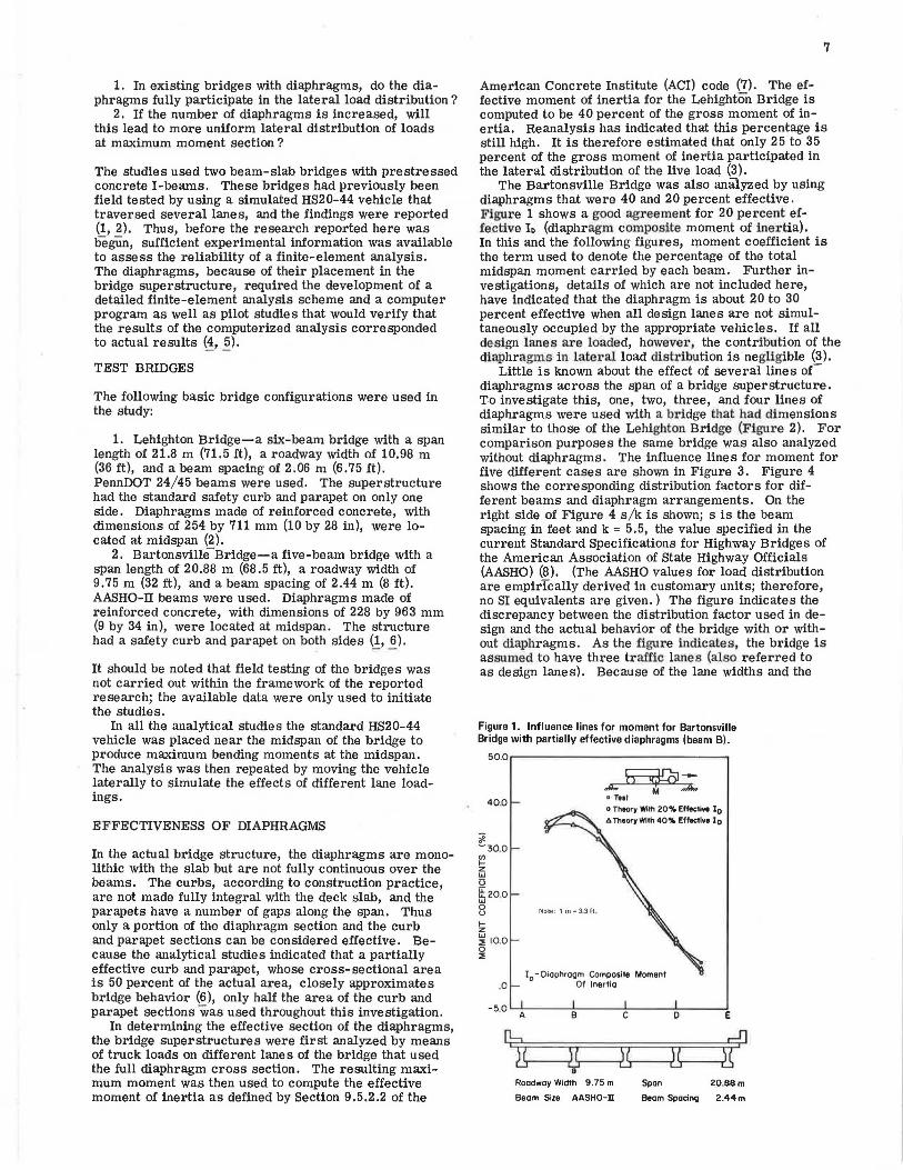
American Concrete Institute (AC!) code (7). The effective moment of inertia for the Lehighton Bridge is computed to be 40 percent of the gross moment of inertia. Reanalysis has indicated that this percentage is still high. It is therefore estimated that only 25 to 35 percent of the gross moment of inertia participated in the lateral distribution of the live load (3).
The Bartonsville Bridge was also analyzed by using diaphragms that were 40 and 20 percent effective. Figure 1 shows a good agreement for 20 percent effective Io (diaphragm composite moment of inertia). In this and the following figures, moment coefficient is the term used to denote the percentage of the total midspan moment carried by each beam. Further investigations, details of which are not included here, have indicated that the diaphragm is about 20 to 30 percent effective when all design lanes are not simultaneously occupied by the appropriate vehicles. If all design lanes are loaded, however, the contribution of the diaphragms in lateral load distribution is negligible (3).
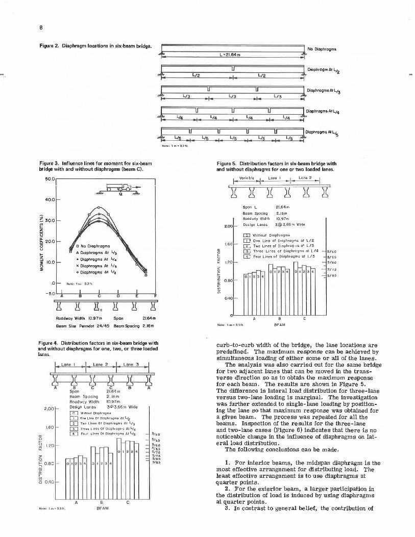
Little is known about the effect of several lines oC diaphragms across the span of a bridge superstructure. To investigate this, one, two, three, and four lines of diaphragms were used with a bridge that had dimensions similar to those of the Lehighton Bridge (Figure 2). For comparison purposes the same bridge was also analyzed without diaphragms. The influence lines for moment for five different cases are shown in Figure 3. Figure 4 shows the corresponding distribution factors for different beams and diaphragm arrangements. On the right side of Figure 4 s/k is shown; s is the beam spacing in feet and k = 5.5, the value specified in the current Standard Specifications for Highway Bridges of the American Association of State Highway Officials (AASHO) (8). (The AASHO values for load distribution are empirically derived in customary units; therefore, no SI equivalents are given.) The figure indicates the discrepancy between the distribution factor used in design and the actual behavior of the bridge with or without diaphragms. As the figure indicates, the bridge is assumed to have three traffic lanes (also referred to as design lanes). Because of the lane widths and the
Figure 1. Influence lines for moment for Bartonsville Bridge with partially effective diaphragms (beam B).
50.0.-----------------.
40.0
ai -30.0 (I) f-z w u it 20.0 w 0 u f-z ~ 10.0 0 :::!:
.0
-5.0
A.~:i: D TIit o Thoory With 20% Ellecll .. 10 t. Theo,y Wllh 40% Ellectlve Io
A
Note: 1 m=331t~
!0
- Diaphragm Composite Moment Of Inertia
B C
e Roadway Width 9. 75 m Span
D
Beam Size AASHO-n Beam Spacinc;i
E
20,BBm
2.44m
8
Figure 2. Diaphragm locations in six-beam bridge.
+ l
L,,4
l /5
l / 2
L/3.
u • I '
•+• Note: 1 m " 3.3ft.
Figure 3. Influence lines for moment for six-beam bridge with and without diaphragms (beam C).
5o.o ~ ------- ------- - ~
40.0
~ 30.0
~ "' u
~ 20.0 0 u
!z ~ 10.0 0 :Ii
.0
-5.0 A
+ Diaphragms Al L/4
X Diaphragms At L/5
o Diaphragms Al Y2
Note: 1 rn • 3,3 ft~
8 C 0
Roadway Width 10.97m Span
E f
21.64m
Beam Size Penndel 24/45 Beam Spacing 2.IBm
Figure 4. Distribution factors in six-beam bridge with and without diaphragms for one, two, or three loaded 1a111,:,.
·~· A 6 C C 8 A
ct: 0
2.00 i-
1.60 '""
t; Li: 1.20 ~
2 0
~ 0.80 -m ii: IV)
o 0.40 '""
Note: 1 m • 3Jrt,
Span 21 .G'l m Beam Spacing 2 .18 m Roadway Width 10.97m Design Lanes [email protected] Wide
[QJ Without Diophrolj)mS
[J=:J One Line Of Diaphragms Al Lt2 [1J Two Lines Of Diophrogms At l/3
u:J Three Lines Of Oiophrat;1ms At L;4 [:±:] Four Lines Of Diaphragms At L;5
-__ ...... -
A
- --O I 2 ~ 4
B BEAM
--- '-0 I ~ 'S 'I
C
----: -
S/5.0
S/5,5
S/6.0 51&.5 SJ7.0 Sn.5 5/B.O S/e.5
L • 2 l.64m + No Diaphragms
·+' l/2
l Diaphragm At L12
u u 1 Diaphragms Al L;3
I • L;3 •I• l/3
•I
u u L,,4 • I • l/4 • I •
l Diaphragms At L14 L14 • I
L/ 5
•+• l./5 !. l /5
•+• L/5
J Diaphragms Al L15
Figure 5. Distribution factors in six-beam bridge with and without diaphragms for one or two loaded lanes.
a: 0 ... u ~ z 0 j:: :,
"' ii: ... u,
0
1--! •m-va_r_ia_b_le • ..,..,., _ _ La_n_e_1 ____ L_an_e_ 2_I
2 .. 00 -
1.60 ,__
1.20 ~
0 .8 0 1--
0.40>-
Span L
Beam Spocin<il
Roadway Width
Design Lones
21.64m
2.1Bm
10.97m
[email protected] Wide
[Q] Without Diaphragms
[I] One Line of D1ophrogms at L/ 2
m Two Lines or Diaphragms at L/3
m Three Lines of Diaphragms at L/4 -
w Four Lines of Diaphragms at L/5 -,- -- -- _ ,....r_ - o'""; 21~ • o r 2 3 4
---D I 2. 3 ,'; -
S/50
S/6.5
S/60
S/7,0
S./ 80
Nau,: I m• :3.31t..
curb-to-curb width of the bridge, the lane locations are bredefined. The maximum resoonse can be achieved bv s imultaneous loading of either some or all of the lanes:
The analysis was also carried out for the same bridge for two adjacent lanes that can be moved in the transverse direction so as to obtain the maximum response for each beam. The results are shown in Figure 5. The difference in lateral load distribution for three-lane versus two-lane loading is marginal. The investigation was further extended to single-lane loading by positioning the lane so that maximum response was obtained for a given beam. The process was repeated for all the beams. Inspection of the results for the three-lane and two-lane cases (Figure 6) indicates that there is no noticeable change in the influence of diaphragms on lateral load distribution.
The following conclusions can be made.
1. For interior beams, the midspan diaphragm is the most effective arrangement for distributing load. The least effective arrangement is to use diaphragms at quarter points.
2. For the exte.rior beam, a larger participation in the distribution of load is induced by using diaphragms at quarter points.
3. In contrast to general belief, the contribution of
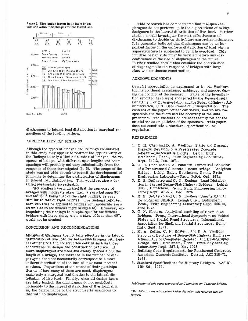
Figure 6. Distribution factors in six-beam bridge with and without diaphragms for one loaded lane .
j Variable Lone
')l Span L 21 ,64 m
2.00 - Beam Spacing 2 . 18 m Roadway VJidfh 10.97 m
Design Lanes I@ 3.66 m Wide
1,60 -"'
[QJ Withour Diaphragms 0 OJ One Line of Diaphragms at L/2 - S/6,D f-u m Two Lines at Diaphragms at L/3 - S/ti.5 <t LL 1.20 >- IT] Three Lines of Diaphragms at L/4 - S/6.0 -z m Four Lines ot Diaphragms ot L/5 - Sl1JJ 0 ;::
- SIB.Cl ::, 2 ir;r !" 0 .80 - 01 -"' -,-_
~ 0 I 2 ~ 4 ~ ,..._
0 0 I 2 3 q
OAO>-
C
Note : 1 m .. 3 ,3 It.
diaphragms to lateral load distribution is marginal regardless of the loading pattern.
APPLICABILITY OF FINDINGS
Although the types of bridges and loadings considered in this study may appear to restrict the applicability of the findings to only a limited number of bridges, the response of bridges with different span lengths and beam spacings will probably not vary substantially from the response of those investigated (3, 5). The scope of the study was not wide enough to permit the development of formulas to determine the participation of diaphragms in lateral load distribution. That would require a detailed parametric investigation.
Pilot studies have indicated that the response of bridges with moderate skew, i.e., a skew between 90° and 60° (90° being that of the right bridge), is very similar to that of right bridges. The findings reported here can thus be applied to bridges with moderate skew as well as to continuous right bridges (3). However, extrapolating the findings to simple- span or continua.us bridges with large skew, e.g., a skew of less than 45°, would not be prudent.
CONCLUSION AND RECOMMENDATIONS
Midspan diaphragms are not fully effective in the lateral distribution of live load for beam-slab bridges with typical dimensions and construction details such as those encountered in design and construction practice. If more diaphragms are used and evenly spaced along the length of a bridge, the increase in the number of diaphragms does not necessarily correspond to a more uniform distribution of the load at maximum moment sections. Regardless of the extent of their participation or of how many of them are used, diaphragms make only a marginal contribution to the lateral distribution of live load. Finally, when all design lanes are fully loaded, the diaphragms do not contribute noticeably to the lateral distribution of live load; that is, the performance of the structure is analogous to that with no diaphragms.
9
This research has demonstrated that midspan diaphragms do not perform up to the expectations of bridge designers in the lateral distribution of live load. Further studies should investigate the cost-effectiveness of diaphragms to decide on their future use or discontinuance. It is generally believed that diaphragms can be an important factor in the uniform distribution of load when a superstructure is subjected to vehicle overload. This intuitive design rule must be verified before any discontinuance of the use of diaphragms in the future. Further studies should also consider the contribution of diaphragms to the response of bridges with large skew and continuous construction.
ACKNOWLEDGMENTS
Grateful appreciation is expressed to D. A~ VanHorn for his continual assistance, guidance, and support during the conduct of the research. Parts of the investigation reported here were sponsored by the Pennsylvania Department of Transportation and the Federal Highway Administration, U. S. Department of Transportation. The contents of the paper reflect our views, and we are responsible for the facts and the accuracy of the data presented. The contents do not necessarily reflect the official views or policies of the sponsors. This paper does not constitute a standard, specification, or regulation.
REFERENCES
1. C. H. Chen and D. A. VanHorn. Static and Dynamic Flexural Behavior of a Prestressed Concrete 1-Beam-Bartonsville Bridge. Lehigh Univ., Bethlehem, Penn., Fritz Engineering Laboratory Rept. 349.2, Jan. 1971.
2. C. H. Chen and D. A. VanHorn. Structural Behavior of a Prestressed Concrete I-Beam Bridge-Lehighton Bridge. Lehigh Univ., Bethlehem, Penn., Fritz Engineering Laboratory Rept. 349.4, Oct. 1971.
3. E. S. DeCastro and C. N. Kostem. Load Distribution in Skewed Beam-Slab Highway Bridges. Lehigh Univ., Bethlehem, Penn., Fritz Engineering Laboratory Rept. 378A .7, Dec. 1975.
4. E. S. Decastro and C. N. Kostem. User's Manual for Program SKBRD. Lehigh Univ., Bethlehem, Penn., Fritz Engineering Laboratory Rept. 400.15, June 1975.
5. C. N. Kostem. Analytical Modeling of Beam-Slab Bridges. Proc., International Symposium on Folded Plates and Spatial Panel Structures, International Association for Shell and Spatial Structures, Udine, Italy, Sept. 1974.
6. M. A. Zellin, C. N. Kostem, and D. A. VanHorn. Structural Behavior of Beam-Slab Highway BridgesA Summary of Completed Research and Bibliography. Lehigh Univ., Bethlehem, Penn., Fritz Engineering Laboratory Rept. 387.1, May 1973.
7. Building Code Requirements for Reinforced Concrete. American Concrete Institute. Detroit, ACI 318-71, 1971.
8. Standard Specifications for Highway Bridges. AASHO, 11th Ed., 1973.
Publication of this paper sponsored by Committee on Concrete Bridges.
*Mr. deCastro was with Lehigh University when this research was performed.