Embed Size (px)
Citation preview

BRIDGE REHABILITATION
Maintaining
and Repairing Existing
Structures

Types of Bridge Rehabilitation
Bridge Deck Overlays Bridge Deck Widening or
Replacement Making Bridge Decks
Continuous and/or Composite
Expansion Device Repair/Replacement
Bridge Rail Retrofits Bridge Repainting Epoxy Chip Seals Bearing
Repair/Replacement Substructure Repair

Original Construction Plans and Shop Plans
Bridge Rehabilitation Project Plans are Generally Developed Using Original Constr. Plans and Shop Plans. Therefore:
Verify all existing dimensions and details. If something is found that deviates from plans,
notify Office of Bridge Design before allowing work to continue.

Bridge Rehabilitation and Maintenance
These Projects Can be More Difficult and Complex Than New Construction.
Carefully review plans sequence. Several types of rehabilitation on one structure. Rehabilitation of several structures may be
included in one project.

Concrete Repair
Most Types of Bridge Rehabilitation/Repair Require Some Type of Concrete Repair: Breakout of Existing Concrete and Placing New Grouting Epoxy Injection of Cracks
Concrete Breakout
Thoroughly Review Plans for Limits of Breakout. Sawcut Perimeter of Breakout Area. Sandblast Contact Surface Before Placing New
Concrete. Care Required Around Resteel to be Re-used. Make Sure Equipment is Suitable for Type of
Breakout.

Concrete Breakout
“EXTREME” Care Required Around Other
Structure Components Absolutely No Nicks or Gouges Allowed on
Steel Girders

Concrete Repair
Immediately Notify the Bridge Construction Engineer
of Any Inadvertent Damage to
Resteel, Girders, or Other Structure Components PRIOR to Continuing Work

Reinforcing Steel
Resteel That is to be Re-Used Shall: Have concrete removed and be abrasive blast cleaned. Shall be properly straightened. Shall be relatively free of gouges.
Gouges shall be no deeper than 1/4 bar diameter. Several consecutive bars damaged should be repaired/replaced
Cut as required by plans to assure proper splice length.
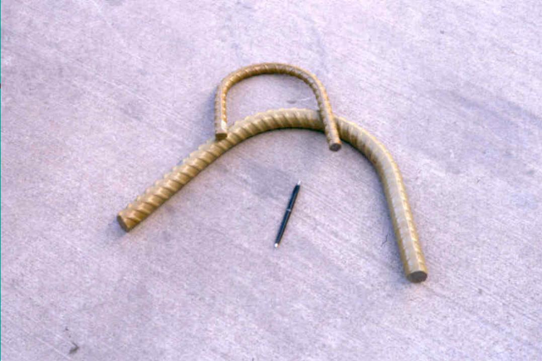
Field Bending Resteel
Bars Need to be Bent Around a Sufficient Radius. Too sharp of radius will result in a kink, which
essentially means that the bar has yielded. Smaller Bars (#4 & #5) Are Usually Bent Easily. Larger Bars May Require Heat. Heat to a dull red Cool Bar at Air Temp.
(Cooling with water will change physical properties)

Resteel Bending Radius
Bar Size Radius (inches) #4 3 #5 3 3/4 #6 4 1/2 #7 5 1/4 #8 6 #9 9 1/2 #10 10 3/4 #11 12

Epoxy Coating
Plans May Require Applying Epoxy Coating to Existing Resteel.
Abrasive blast clean bar immediately prior to application. Use Epoxy Touch-up Coating Material supplied by a
manufacturer of epoxy coated resteel. (Do Not Allow Coatings from Spray Cans)
Make sure all surfaces are adequately coated. Cure for 24 hours or as per manufacturer’s
recommendations, whichever is more stringent.

Mechanical Rebar Splices
Used to Splice Resteel When a Conventional Lap Splice is not Practical.
Use only when specified or approved by Bridge Constr. Engineer.
Must be capable of developing 125% of the yield strength of bar. (Make sure intended for Grade 60.)
Epoxy coated or other approved corrosion resistant material required when splicing epoxy coated resteel.


Grout Repairs
Used When Concrete Breakout and Replacement is not Structurally Necessary.
Used in Voids and Gaps That Are Large Enough to
Allow Cleaning and That Can be Easily Accessed.
Used to Repair “Honeycomb.”

Surface Preparation
Remove All Loose or Foreign Material. Chip Away Any Unsound Concrete. Honeycomb area should be chipped out to sound
concrete.
Flush Surfaces With Water and Allow to Dry to a Surface Dry Condition.
Grout
Sand/Cement Grout is Used Unless Otherwise Specified or Approved (Section 460.3.R).
When Commercial Grout is Specified or
Approved, Grout Shall Conform to the Following: Portland Cement Based Non-Metallic (No Aluminum Powder) Non-Shrink

Placement of Grout
Grout Should be Tightly Packed Into All Recesses and Holes to Completely Fill the Voids.
Grout Should be Wet Cured for not Less Than 3 Days, or as Required by the Manufacturer’s Recommendations.

Epoxy Injection
Tighter Cracks and Voids Are Repaired by Injecting Epoxy Resin Adhesive Into Them.
Clean concrete surface along crack. Blow foreign material out of crack using compressed air. Injection ports are installed in the crack at intervals. Crack is sealed between injection ports. Epoxy is injected at lower port until epoxy runs out of next port
up. Lower port is sealed and process continued in next port up.

Epoxy Resin Adhesive
Epoxy Resin Adhesive Shall Conform to all Provision Including Gel Time and Epoxy Content
AASHTO M235 (ASTM C881) and Shall be of the Proper Type, Grade and Class.

Epoxy Resin Adhesive
Type: Separates epoxies by intended application Most often specified in the plans (Type IV generally specified)
Grade: Separates epoxies by flow characteristics Grade 1 is low viscosity (very flowable) Grade 2 is medium viscosity Grade 3 is non-sagging
Class: Defines allowable temperature ranges for use

Installing Dowel Bars In Concrete
Many Types of Repairs Require That Holes
be Drilled Into Concrete and Dowel Bars be Epoxied Into the Holes

Dowel Bar Installation Procedures
Drill Holes in Concrete to Diameter and Depth Specified Clean Out Hole With Compressed Air Make Sure That Epoxy is mixed According to
manufactures Specifications Beginning at Back of Hole, Fill Hole 1/3 to 1/2 Full of
Epoxy Insert Dowel Bar by Rotating Bar While Inserting Into
the Hole. (Dipping bar into epoxy or painting epoxy onto bar and then inserting is NOT allowed.)

Bridge Deck Overlays
Low Slump Dense Concrete


Low Slump Dense Concrete Overlay
Low Slump Dense Concrete (LSDC) is Most Common Type of Bridge Deck Overlay Used.
Is a very stiff, low slump, high density, low permeability concrete.
Protects against chloride penetration.

Surface Preparation
The Bond Between the Bridge Deck and the Overlay is Critical, Therefore, Special
Attention Needs to Given to Proper Surface Preparation.

Equipment Required
Scarifier or Milling Machine Power Hand Tools 30 lb. Jack Hammers 15 lb. Chipping Hammers
Concrete Saw Abrasive Blasting Equipment

Types of Concrete Removal
Several Types of Concrete Removal Are Required to Properly Prepare the Surface and
to Remove Delaminated Concrete.

Type 1A Removal
Type 1A Removal Intended to Remove Surface Contaminants and to Provide a Sound Bonding
Surface
Consists Primarily of Scarifying 1/4 Inch Off of Entire Deck (Curb Face and Curb Lines Done by Hand)
May Also Include Scarification of Approaches Additional Depth of Scarification May be Specified in Some
Areas to Improve Profile Accurate Grade Control During Scarification is Essential


Type 2A Removal
Type 2A Removal is intended to be used when removing an existing overlay Consists of additional passes with scarification equipment to
remove thin unsound areas of previous overlay Only used when ordered by the Engineer Extreme care must be used to assure no damage to resteel
Use cover meter prior to scarification Stop if steel is encountered


Extra Depth Removal
Additional Concrete Removal May be Required to Remove Delaminated Concrete.
Areas of Delaminated Concrete Are Determined by Sounding: Chain Drag Hammer
These Areas Are Marked Out, The Removal Done, and Areas Measured and Documented for Payment.


Type 1B Removal
Type 1B Removal is Only Done in Areas Determined to be Delaminated and That Have Been Marked Out.
Depth of Type 1B Removal is From the Top Deck Surface Down to the Top of the Top Mat of Resteel.
After Type 1B Removal is Complete, the Areas Are Re-Sounded to Determine if Additional Depth of Removal is Required.


Type 1C Removal
Type 1C Removal is Done Only in Areas Where Delaminated Concrete is Found to be Deeper Than the Top of the Top Mat of Resteel.
The Bottom Limit of the Type 1C Removal Will Vary Anywhere From the Top Limit Down to the Top of the Bottom Mat of Resteel.
These Areas Should be Re-Sounded Periodically During Removal, and Removal Should Cease When Sound Concrete is Encountered.


Type 1D Removal
Type 1D Removal is Done Only in Areas Where Delaminated Concrete is Found to be Deeper Than the Top of the Bottom Mat of Resteel.
Areas of Type 1C Removal Are Re-Sounded and if
Delaminated Concrete is Found, These Areas are Then Removed to Full Depth.
Type B Removal
Type B Concrete Removal is the Removal of Concrete From Around the Periphery of Resteel.
Is Generally Used When an Isolated Rebar Has Lost Concrete Bond on More Than 1/2 of the Circumference. Type 1C Removal may be ordered by the Engineer in lieu of
Type B Removal. Removal Should Result in a Minimum of 3/4 Inch
Clearance Around the Bar.
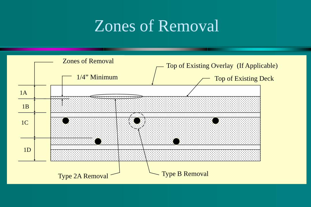
Zones of Removal
Top of Existing Overlay (If Applicable)
Top of Existing Deck 1/4” Minimum
1A
1C
1D
1B
Type B Removal
Zones of Removal
Type 2A Removal

Concrete Removal Specification Requirements
Scarified Surface Shall be Continuously Kept Clean. Upon Completion of Type 1A Removal (Scarification):
Traffic is NOT permitted on the scarified surface. Construction equipment on the scarified surface should be
minimized. Equipment that is allowed on deck shall be equipped with
diapers to prevent oil or grease from contaminating surface. If grease or oil contamination does occur, additional
scarification, removal, or detergent cleaning is required.

Concrete Removal Specification Requirements
Jack Hammers No Heavier Than 30 Lbs. Are Allowed for Type 1B Removal (Down to Top Mat of Resteel).
Jack Hammers No Heavier Than 15 Lbs. Are Required When Working Around Resteel.
Extreme Care Shall be Taken to Prevent Damage to Resteel

Concrete Removal Specification Requirements
Edges of Removal Area Shall be Nearly Vertical.
Nearly Vertical or Slightly Tapering Inward. Reverse Taper
CORRECT INCORRECT

Too Much Removal?
If More Than 30% of: The longitudinal bars on a continuous concrete bridge OR The transverse bars on a girder bridge
Are Freed-Up in Any 10 Foot Wide Area, Contact the Bridge Construction Engineer Before Continuing Removal


Abrasive Blast Cleaning of Deck
No More Than 24 Hours Prior to Concrete Placement, the Deck Surface Shall be Abrasive Blast Cleaned To Remove Contaminants To Enhance Bond Re-Blasting is Required When: Delays result in exceeding 24 hour limitation Rain or other contamination occurs after initial blasting
Thoroughly Blow Off Deck With Compressed Air

Full Depth Holes
Deep Holes Created By Type 1C / 1D Removal:
Require Shoring From Bottom Side of Deck. Are Filled Up to the Level of The Scarified Surface Prior
to Placement of Low Slump Dense Concrete Overlay. Use Class A45 Concrete Cure With Wet Burlap and Poly Sheeting Until
2000psi

Concrete Mix Design
Low Slump Dense Concrete Mix Design Per Section 550 of Standard Specifications
Absolute Volume Per Unit Volume Course Aggregate 0.312088 Fine Aggregate 0.312088 Air 0.060000 Water 0.160255 Cement 0.155569 1.000000
Concrete Mix Adjustments
Mix Proportions Need to be Adjusted for Actual
Specific Gravity of Materials
Specific Gravity = (Material Density) / (Density of Water)

Example Mix Adjustment
Specific Gravities * Rock = 2.65 * Sand = 2.65 ⊗ Cement = 3.14 Water = 1.00 * Specific Gravity may be obtained
from Office of Materials. ⊗ From Cement Cert’s. (Usually ≅ 3.14)
Example: Rock: 2.65(62.4)(27)(0.312088) = 1394 Lbs. Sand: 2.65(62.4)(27)(0.312088) = 1394 Lbs. Cement: 3.14(62.4)(27)(0.155569) = 823 Lbs. Water: 1.00(62.4)(27)(0.160255) = 270 Lbs. No Adjustment for Air Required Still Need to Adjust for Moisture in
Aggregate.

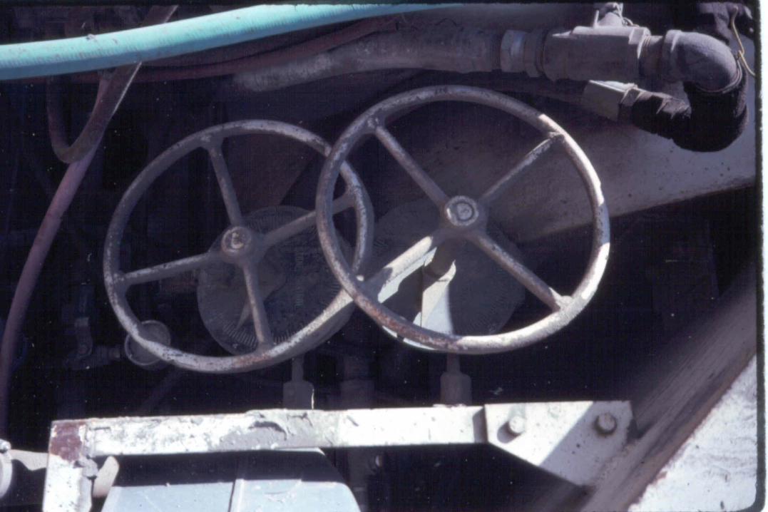
Mobile Concrete Mixer
Specifications Require That Concrete Be
Proportioned & Mixed By A
“Self Contained Mobile Continuous Mixing Unit” (Conforming to Section 460.3.E)


Mobile Mixer Calibration
Mobile Concrete Mixers Are Required to be
Calibrated at Least Once Annually.
Yield Test Performed Prior to Each Pour. If yield test indicates mobile mixer is not in proper
calibration, re-calibrate and forward mobile mixer calibration form to the Concrete Engineer.


Yield Test
1/4 Cubic Yard Form Supplied by Contractor Take measurements to verify form is proper size
Determine Cement Meter Count for 1/4 Cu. Yard Set Mobile Mixer at Operating Speed Set Meter Count at Zero Discharge Concrete until Cement Reading is Reached Form Should be Full, but With No Overspill


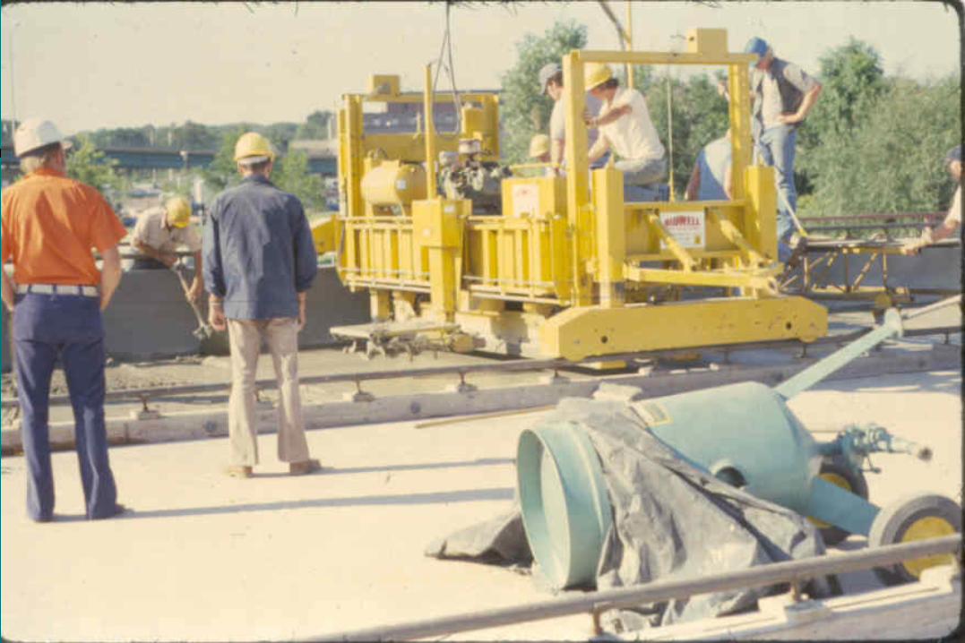
Low Slump Finish Machine
A Special Finish Machine Designed for Use on Low Slump Dense Concrete is Required. Mechanical strike off Oscillating screed Capable of forward and reverse motion. Capable of raising screeds to clear surface when
traveling in reverse Capable of providing control of vertical position, tilt,
and crown shape

Finish Machine Screed
Additional Screed(s) Requirements: Effective weight of 75 psf. Screed face at least 5 inches in width. Turned up or rounded leading edge. Internal Vibrators (Min. of one per 5 ft). Capable of finishing to within 1” of curb face. Extend at least 6 inches beyond centerline sawcut.


Setting Screed Rails To Grade
Screed Rails Should be Set to Plans Grade. Make a “Dry Run” with the Finish Machine and
Check Distance from Bottom of Screed to the Top of the Scarified Surface. If measurements indicate that the overlay thickness is:
Less than 2 inches Greater than 3 inches
then, gradeline adjustments may be required.

Gradeline Adjustments
Items to Consider When Making Gradeline Adjustments: Will smooth ride be maintained?
On the Bridge On Approaches
Will water drain off deck without ponding? How will adjacent lane be affected?

Low Slump Dense Concrete Limitations
40 Ft. Per Hour Minimum Rate of Pour.
Maximum Width of Placement is 24 Feet.
Seasonal Limitations Not After October 1 Not Before May 1
Surface Temperature ≥ 40°F
Concrete Temperature Placed Between 45°F and 80°F Maintained > 45°F for 72 Hours
After Placement No Placement Allowed if Air
Temperature is > 85°F. May be Necessary to Place
Concrete at Night or Early AM If > 80°F, Fogging Equip.
Required

Limitations Due to Hot Weather
During Periods of Extreme Hot Weather it May be Difficult to Maintain the Concrete Temperature Below the Specified Maximum of 80°F.
The Engineer May Authorize the Maximum Temperature to Be Increased to 85°F Provided the Following Conditions Are Met:
The Course Aggregate Piles are Flushed With Cool Water. Wet Burlap is Placed as Soon as the Concrete Surface Will Support It
Without Deformation. Water Tank on the Mobile Mixer is Not Filled Until Immediately Prior to
Concrete Placement, at Which Time It is Filled With Cold Water. (The Addition of Ice to the Water Tank is Permitted.)

Concrete Requirements
Slump: 1 Inch Maximum Air Content: 5% to 7% Compacted Density to 98% of Rodded Unit Weight Determined by use of Nuclear Gage.
Required Testing Slump Test Air Content Concrete Temp. Unit Weight Nuclear Density Testing


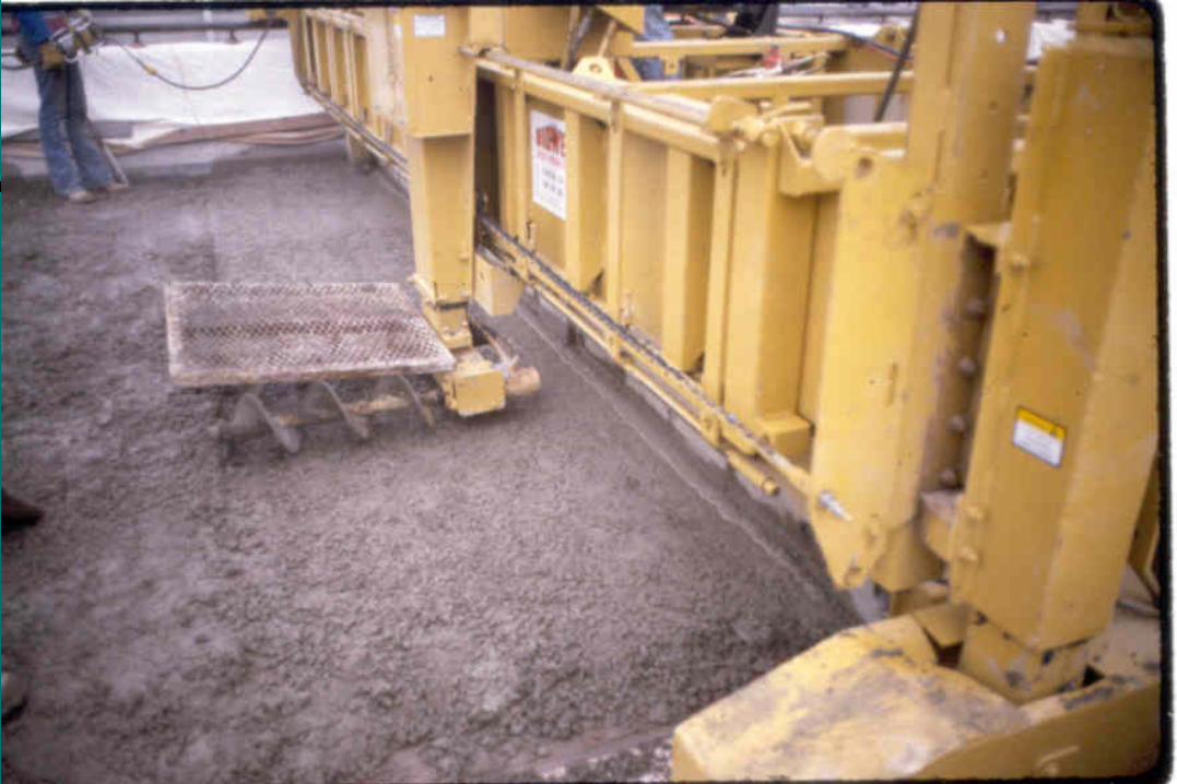
Placement of Low Slump Dense Concrete
Clean, Dry Surface Must be Maintained. Grout is Applied to Surface Immediately Prior to
Concrete Placement. Grout shall be scrubbed into surface, abutting curb face, and
vertical surface of previously placed lane. 50 % Cement & 50% Sand (by weight). Just enough water added to form a thick slurry. Must be placed such that concrete is placed prior to grout
drying. Excess grout should not be allowed to pond in low areas.


Placement of Low Slump Dense Concrete
Concrete Usually Place by “Concrete Buggy”. Plywood, plastic, or other adequate material to protect
surface from contamination Finish Machine Shall Mechanically Consolidate the
Concrete to 98% of the Rodded Unit Weight. Suitable “Spud Vibrator” Required for: Longitudinal joints at curb lines and adjacent lanes In areas where overlay thickness is greater than 3 inches.


Finishing
Concrete Shall be Struck Off 1/4 Inch Above Grade. Concrete Shall be Consolidated and Finished by the Finish
Machine. Hand Finishing May be Required Behind the Finish
Machine to Provide a Tight, Uniform Surface. (Do Not Allow Finishers To Apply Water To Deck During Hand Finishing)
After Finishing, All Vertical Joints With Adjacent Concrete Shall be Sealed by Painting With Grout.
The Surface Shall be Broomed and Transverse Tined.


Curing
Place “WET” Burlap on Finished Surface. Burlap should be wet, but well drained. Do NOT allow dry burlap to be placed and then
wetted. Burlap should be placed as soon as surface will
support it without deformation. Usually approx. 10 minutes Failure to apply within 30 minutes shall be cause for
rejection

Curing
The Wet Burlap Cure is Required for at Least 72 Hours.
Burlap is kept continuously wet by automatic
sprinkling or wetting system.
After 24 hours, the Contractor may cover the wet burlap with white polyethylene sheeting in lieu of the sprinkling or wetting system.

Superimposed Loads
No Traffic on Completed Surface for 72 Hours. Adjacent Concrete Shall Not Be Placed for 36
Hours Except Continuation From a Transverse
Construction Joint in the Same Lane is Permitted When the Concrete is 12 Hours Old
Low Slump Dense Concrete That Is NOT In Specification
Do Not Allow Out-of-specification Material to be Placed.
Out-of-Specification Material Inadvertently Placed Should be Removed and Replaced. Small amounts can be shoveled off or removed by
“BobCat” and placement continued. Large amounts of out-of-specification concrete should
result in removal by “Bobcat” or small loader and the area being flushed with water.

Epoxy Chip Seal
Consists of an Epoxy Resin and Cover Aggregate
Placed On a Properly Prepared Concrete Surface

Surface Preparation
Surface Preparation is Performed by: Diamond Grinding Removal of delaminated or loose concrete Filling removal holes with concrete Shot-blasting to ICRI concrete surface profile
(CSP-5) Abrasive Blast Cleaning the concrete surface Cleaning with Compressed Air or Vacuum

Concrete Removal / Replacement
Delaminated or Loose Concrete Shall be Removed. Concrete Removal and Replacement Procedures Are Much Like
Those Used for Low Slump Overlays: Sound Deck Remove Unsound Concrete Abrasive Blast Clean Removal Areas Fill with bag mix according to manufacturer’s
recommendations Place, Float, and Wet Cure for 48 hrs. Dry for 48 hrs.

Bridge Deck Preparation
After bridge deck is ground the entire Surface shall be thoroughly shot-blasted to ICRI concrete surface profile (CSP-5) to remove all Contaminants.
The Entire Deck Surface is Blown Clean with Compressed Air or Vacuum Cleaned to Remove All Dust and Loose Debris.
Abrasive Blast Cleaning Shall be Done Within 24
Hours of Placement of the Epoxy Chip Seal


Epoxy Chip Seal Placement Limitations
Epoxy Chip Seal Cannot be Placed on Any New Concrete for 28 Days. Traffic is permitted when concrete has attained 4000 psi.
Deck and ambient temperature between 50° and 100° Surface Shall Dry for 24 Hours after Rain. Epoxy and Bridge Deck Temp. is Anticipated to be
65°F or Greater for at Least 4 Hours.

Epoxy Requirements
Two Component Epoxy Base Component Hardener Epoxy must be stored out of the sun and kept dry
and must remain between 50° and 85° degrees


Placement of First coat of Epoxy
Mix, Store and Apply Epoxy in Accordance With Manufacturer’s Recommendations. Broadcast Over Surface with “Notched
Squeegee” at a minimum spread rate of one gallon per 40 square feet


Aggregate Application
Aggregate: Basalt Cover Aggregate applied immediately after
epoxy is applied Apply aggregate to refusal reapply on wet spots
that appear


Placement of Second coat of Epoxy
After First coat has sufficient time to harden (2 to 6 hours depending on temp.) remove excess aggregate
In the event of rain the deck must be dried for 24 hours and deck will be abrasive blasted
Apply second coat of epoxy with a minimum of 1 gallon per 20 square feet
Broadcast aggregate to refusal


Removal of Excess Aggregate
After Epoxy Has Cured to a Tack-Free Touch, the Excess Aggregate is Removed by:
Brooming High-Pressure Air Vacuuming


Acceptance
Pull off test must be preformed prior to opening lane to traffic.
Pull-off test should be preformed according to ASTM D4541-02 with the addition of using a diamond or carbide-tipped core drill bit to score through the chip seal with little of no removal of concrete prior to placement of the detaching assembly.
Pull-off tests with a resulting load of 250 psi or more shall be considered passing. All pull-off tests with a resulting load of less than 250 psi shall be retested according to the type of failure. There are three possibilities or combinations thereof as described below:
Failure in the concrete substrate (concrete failure) - The Contractor shall
perform one additional test within one foot of the failing test. Detaching assembly adhesive failure (adhesive failure) - The Contractor
shall perform one additional test within one foot of the failing test. Separation of the epoxy chip seal from the concrete surface (epoxy failure),
or pullout of the aggregate from the epoxy (epoxy or aggregate failure) - The Contractor shall perform two additional pull-off tests. One test shall be performed between 10 ft and 15 ft back from the failing test and one test shall be performed between 10 ft and 15 ft ahead of the failing test.


Other Types of Bridge Rehabilitation
Bridge Deck Widening / Replacement
Making Bridge Decks Continuous or Composite
Bridge Repainting

Questions