Embed Size (px)
Citation preview

Bridge Bearingsand Expansion Joints

CCL Bridge BearingsCCL bearings are widely used in structural, marine and civilengineering applications, and particularly bridges, to transfervertical forces from one structural member to another. They arealso required to restrict or permit linear or rotational movementin the horizontal plane. Where horizontal movement is restrictedthe horizontal forces will be transferred through the bearing tothe lower structure. Bearings are available in carbon steel asstandard, and in stainless steel for applications where corrosionis a potential problem or life cycle costing benefits are sought.As standard CCL bearings are designed to meet therequirements of BS 5400 : Section 9.1 and 9.2: 1983
DesignDue to the complexity of bridge bearing design CCL providetechnical assistance on the selection of the most appropriatebearings. Our technical staff will be pleased to discuss individualapplications. In order to facilitate the design process relevantinformation should wherever possible be supplied in accordancewith BS5400 section 9.1 table 9.
Special BearingsCCL can also manufacture bearings to suit loadings, rotationaland movement requirements outside the scope of the standard
range. These can include factors such as uplift, environmental conditions, seismic effects andtemporary constructional requirements.
TestingCCL has well equipped in-house facilities, which are regularly used for testing bearings. In-housetesting is carried out in accordance with BS 5400: Section 9.2: 1983 and BS EN ISO 9001: 1994.
Our compression test frame is one of the largest in the UK. An imposed rotation of the bearing canbe accommodated when this is required.
Tests can be observed by independentwitnesses when this is required.
CCL Bridge Bearings
2

Selection of BearingsSelection of Bearings
23
There are many factors to be considered before the most appropriate arrangement of bearings canbe determined for a particular application. The table below provides an overall indication of thefeatures of each type of bearing.
Key Suitable ß Not suitable Limited Indicates that either Longitudinal or Transverse loads/movements can be permitted, not both.
Mechanical Pot BearingsMechanical pot bearings are available in three types; fixed, guided sliding and free sliding, and in avariety of capacities. All three types allow rotation. Fixed bearings provide restraint in all horizontaldirections. Guided bearings allow movement in one horizontal direction and provide restraint in theother direction. Free Sliding bearings allow movement in all horizontal directions.
Fixed Pin or Removable Dowel BearingsThe Fixed Pin bearing provides restraint in all horizontal directions and can be used with LaminatedElastomeric bearings, the Elastomeric bearing supporting the vertical load and the Fixed Pin bearingtaking the horizontal loads.
Uniguide or Shear Key BearingsUniguide bearings can be used at the opposite end to Fixed Pin bearings to allow expansion fromthe fixed end, but provide restraint in the other direction. Uniguide bearings can be used inconjunction with Laminated Elastomeric bearings, the Elastomeric bearings supporting the verticalload, the Uniguide bearing taking the lateral horizontal load.
Laminated Elastomeric BearingsLaminated Elastomeric bearings allow horizontal movement by shear deflection, and allow rotationby angular deformation. Where horizontal movement needs to be controlled or large horizontal loadsresisted, Laminated Elastomeric bearings should be used in conjunction with Fixed Pin or Uniguidebearings. If required laminated elastomeric bearings can be fitted with a vulcanised PTFE sheet andslider plate to accommodate large translations.
Plain Pad and Strip BearingsUn-reinforced elastomeric pads and strips are used where low loads and small movements areexpected. They are the simplest type of bearing, readily available and easy to install.
Direction of Force Rotation Permitted Movement PermittedBearing Type Vertical Longitudinal Transverse Longitudinal Transverse Longitudinal Transverse
Fixed Pot ß ßFree Sliding Pot ß ßGuided Sliding Pot
Fixed Pin ß ß ßUniguide ßLaminated Elastomeric
Plain Pad & Strip

Arrangement of BearingsArrangement of Bearings
4
Mechanical Pot Bearings Elastomeric, Fixed Pin & Uniguide Bearings
Fixed Pot BearingAll translations are fixed, rotation possible
Guided Sliding BearingHorizontal movement in one direction, rotation possible.
Free Sliding BearingHorizontal movement in all directions, rotation possible.
Elastomeric BearingRotation and movement possible in all directions.
Uniguide BearingMovement allowed in one direction only, no vertical load.
Fixed Pin BearingAll translations are fixed, rotation possible, no vertical load.

PF Fixed Pot Bearing
Fixed bearings carry vertical load whilst providing restraint inall horizontal directions. There are three types of mechanicalpot bearings, all of which are available in a range of capacitiesand sizes. Each type utilises a piston, rubber disc and pot base,with variations to suit.
The projecting piston of the top plate is fully retained by themetal pot of the bottom plate to provide full restraint in thehorizontal plane. The deformation of the elastomeric discallows multi-directional rotation to take place.
PF 50 PF100 PF150 PF200 PF250 PF300 PF400 PF500 PF750 PF1000 PF1500 PF2000
SLS Permanent Vertical Load (kN) 330 670 1000 1330 1660 2000 2670 3330 5000 6660 10000 13330
SLS Total Vertical Load (kN) 500 1000 1500 2000 2500 3000 4000 5000 7500 10000 15000 20000
SLS Horizontal Load (kN) 110 210 225 255 350 380 545 810 930 1300 1850 2100
ULS Vertical Load (kN) 650 1300 2000 2660 3330 4000 5330 6500 9750 13000 19500 26000
ULS Horizontal Load (kN) 140 270 300 330 470 500 710 1050 1200 1690 2400 2700
Overall Height a 54 71 84 89 103 115 131 140 166 202 247 282
Base Length and Width b 180 245 300 350 385 415 485 545 670 770 940 1085
Base Bolt Ctrs (Square) d 145 200 255 305 320 360 420 460 590 675 830 975
Top Plate Length and Width f 180 245 300 350 385 415 485 545 670 770 940 1085
Top Bolt Ctrs (Square) h 145 200 255 305 320 360 420 460 590 675 830 975
Bolt Size M12 M16 M16 M16 M20 M20 M24 M30 M30 M36 M42 M42
PF Fixed Pot Bearing
5
PF Fixed Pot Bearing Indicative Table of Dimensions
Assumptions: 1. Minimum load is at least 20% of total load 2. 30% of minimum load is used as frictional resistance to horizontal load 3. Total rotations are up to 0.015 rads4. Lower and upper seating pressures approach 20N/mm2 at SLS 5. Lower and upper seating pressures approach 30N/mm2 at ULS 6. 25mm mortar under base.
f
h
d
b
Top Plate
Seal
Pot Base
Elastomeric Disc
a
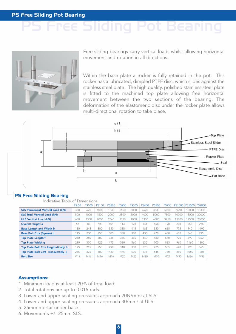
PS Free Sliding Pot BearingFree sliding bearings carry vertical loads whilst allowing horizontalmovement and rotation in all directions.
Within the base plate a rocker is fully retained in the pot. Thisrocker has a lubricated, dimpled PTFE disc, which slides against thestainless steel plate. The high quality, polished stainless steel plateis fitted to the machined top plate allowing free horizontalmovement between the two sections of the bearing. Thedeformation of the elastomeric disc under the rocker plate allowsmulti-directional rotation to take place.
PS Free Sliding Pot Bearing
6
PS 50 PS100 PS150 PS200 PS250 PS300 PS400 PS500 PS750 PS1000 PS1500 PS2000
SLS Permanent Vertical Load (kN) 330 670 1000 1330 1660 2000 2670 3330 5000 6660 10000 13330
SLS Total Vertical Load (kN) 500 1000 1500 2000 2500 3000 4000 5000 7500 10000 15000 20000
ULS Vertical Load (kN) 650 1300 2000 2660 3330 4000 5330 6500 9750 13000 19500 26000
Overall Height a 62 85 95 101 113 128 144 158 190 208 253 296
Base Length and Width b 180 245 300 350 385 415 485 550 665 775 940 1190
Base Bolt Ctrs (Square) d 145 200 255 305 330 360 430 470 600 650 840 995
Top Plate Length f 210 260 300 335 365 385 440 480 570 720 890 960
Top Plate Width g 290 370 425 475 530 560 630 700 825 960 1160 1300
Top Plate Bolt Ctrs longitudinally h 175 215 250 290 310 330 375 425 505 640 790 865
Top Plate Bolt Ctrs Transversely j 255 325 380 430 475 505 575 645 760 880 1060 1205
Bolt Size M12 M16 M16 M16 M20 M20 M20 M20 M24 M30 M36 M36
PS Free Sliding BearingIndicative Table of Dimensions
Assumptions: 1. Minimum load is at least 20% of total load 2. Total rotations are up to 0.015 rads3. Lower and upper seating pressures approach 20N/mm2 at SLS 4. Lower and upper seating pressures approach 30/mm2 at ULS 5. 25mm mortar under base.6. Movements +/- 25mm SLS.
g / f
h / j
d
b
Top Plate
Stainless Steel Slider
PTFE Disc
Rocker Plate
Seal
Elastomeric Disc
Pot Base

PG Guided Sliding Pot BearingGuided sliding bearings carry vertical loads whilst allowingmovement in one direction and providing restraint perpendicular tothis movement. They also allow rotation in all directions.
Within the base plate a rocker is fully retained in the pot. This rockerhas a lubricated, dimpled PTFE disc, which slides against thestainless steel plate. The high quality, polished stainless steel plateis fitted to the machined top plate between two guide rails, whichresist the horizontal load in one direction. Horizontal movementoccurs along the length of the guide rails. The deformation of theelastomeric disc under the rocker plate allows multi-directionalrotation to take place.
PG Guided Sliding Pot Bearing
7
PG50 PG100 PG150 PG200 PG250 PG300 PG400 PG500 PG750 PG1000 PG1500 PG2000
SLS Permanent Vertical Load (kN) 330 660 1000 1330 1660 2000 2670 3330 5000 6660 10000 1333
SLS Total Vertical Load (kN) 500 1000 1500 2000 2500 3000 4000 5000 7500 10000 15000 20000
SLS Horizontal Load (kN) 100 200 220 240 350 380 510 610 890 1350 1700 2100
ULS Vertical Load (kN) 650 1300 2000 2660 3330 4000 5330 6500 9750 13000 19500 26000
ULS Horizontal Load (kN) 130 250 280 310 440 475 670 790 1120 1580 2200 2550
Overall Height a 100 114 122 134 149 159 175 89 227 270 306 360
Base Length and Width b 180 245 300 350 385 415 485 545 670 770 940 1085
Base Bolt Ctrs (Square) d 145 200 255 305 330 360 420 460 590 675 830 975
Top Plate Length f 225 275 315 350 380 410 460 500 600 720 900 1000
Top Plate Width g 315 380 415 470 515 545 615 690 810 935 1140 1280
Top Plate Bolt Ctrs Longitudinally h 190 230 270 305 325 355 395 420 520 625 790 890
Top Plate Bolt Ctrs Transversely j 280 335 370 425 460 490 550 610 730 840 1030 1170
Bolt Size M12 M16 M16 M16 M20 M20 M24 M30 M30 M36 M42 M42
PG Guided Sliding Pot BearingIndicative Table of Dimensions
Assumptions:1. Minimum load is at least 20% of total load 2. 30% of minimum load is used as frictional resistance to horizontal load 3. Total rotations are up to 0.015 rads4. Lower and upper seating pressures approach 20N/mm2 at SLS 5. Lower and upper seating pressures approach 30N/mm2 at ULS 6. 25mm mortar under base.7. Movements +/- 25mm SLS.
Top Plate
PTFE Disc
Guide Bar
Rocker Plate
Seal
Stainless Steel Slider
Elastomeric Disc
Pot Baseb
d
g / f
h / j
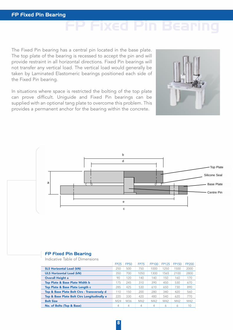
FP Fixed Pin BearingThe Fixed Pin bearing has a central pin located in the base plate.The top plate of the bearing is recessed to accept the pin and willprovide restraint in all horizontal directions. Fixed Pin bearings willnot transfer any vertical load. The vertical load would generally betaken by Laminated Elastomeric bearings positioned each side ofthe Fixed Pin bearing.
In situations where space is restricted the bolting of the top platecan prove difficult. Uniguide and Fixed Pin bearings can besupplied with an optional tang plate to overcome this problem. Thisprovides a permanent anchor for the bearing within the concrete.
FP Fixed Pin BearingIndicative Table of Dimensions
FP25 FP50 FP75 FP100 FP125 FP150 FP200
SLS Horizontal Load (kN) 250 500 750 1000 1250 1500 2000
ULS Horizontal Load (kN) 350 700 1050 1300 1565 2100 2800
Overall Height a 90 120 140 140 150 160 170
Top Plate & Base Plate Width b 175 245 310 390 450 530 670
Top Plate & Base Plate Length c 285 425 530 610 650 730 890
Top & Base Plate Bolt Ctrs - Transversely d 110 150 200 280 340 420 560
Top & Base Plate Bolt Ctrs Longitudinally e 220 330 420 480 540 620 770
Bolt Size M24 M36 M42 M42 M42 M42 M42
No. of Bolts (Top & Base) 4 4 4 4 6 6 10
FP Fixed Pin Bearing
8
Top Plate
b
d
e
c
Silicone Seal
Base Plate
Centre Pin
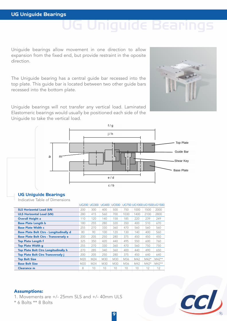
UG Uniguide BearingsUniguide bearings allow movement in one direction to allowexpansion from the fixed end, but provide restraint in the opositedirection.
The Uniguide bearing has a central guide bar recessed into thetop plate. This guide bar is located between two other guide barsrecessed into the bottom plate.
Uniguide bearings will not transfer any vertical load. LaminatedElastomeric bearings would usually be positioned each side of theUniguide to take the vertical load.
UG Uniguide Bearings
9
UG Uniguide BearingsIndicative Table of Dimensions
SLS Horizontal Load (kN) 200 300 400 500 750 1000 1500 2000
ULS Horizontal Load (kN) 280 415 560 700 1030 1400 2100 2800
Overall Height a 110 120 140 158 185 220 239 249
Base Plate Length b 180 255 280 320 350 400 510 670
Base Plate Width c 255 270 330 360 470 560 560 560
Base Plate Bolt Ctrs - Longitudinally d 80 90 100 120 130 140 400 560
Base Plate Bolt Ctrs - Transversely e 200 205 250 280 375 450 450 450
Top Plate Length f 325 350 420 440 495 550 600 760
Top Plate Width g 255 270 330 360 470 560 750 750
Top Plate Bolt Ctrs Longitudinally h 270 285 340 360 400 440 490 650
Top Plate Bolt Ctrs Transversely j 200 205 250 280 375 450 640 640
Top Bolt Size M20 M24 M30 M30 M36 M42 M42* M42**
Base Bolt Size M20 M24 M30 M30 M36 M42 M42* M42**
Clearance m 8 10 10 10 10 10 12 12
Assumptions: 1. Movements are +/- 25mm SLS and +/- 40mm ULS* 6 Bolts ** 8 Bolts
UG200 UG400UG300 UG500 UG750 UG1000 UG1500UG1500
Top Plate
Guide Bar
Shear Key
Base Plate
c / b
e / d
j / h
f / g
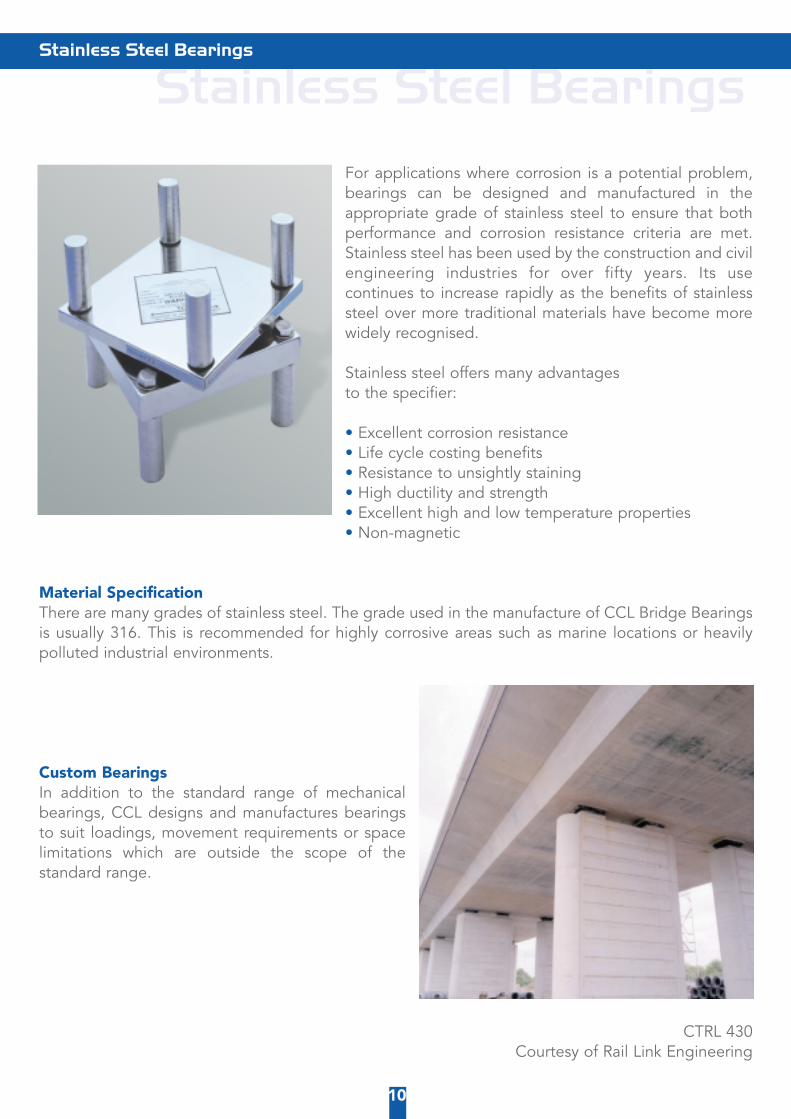
Stainless Steel BearingsFor applications where corrosion is a potential problem,bearings can be designed and manufactured in theappropriate grade of stainless steel to ensure that bothperformance and corrosion resistance criteria are met.Stainless steel has been used by the construction and civilengineering industries for over fifty years. Its usecontinues to increase rapidly as the benefits of stainlesssteel over more traditional materials have become morewidely recognised.
Stainless steel offers many advantages to the specifier:
• Excellent corrosion resistance• Life cycle costing benefits• Resistance to unsightly staining• High ductility and strength• Excellent high and low temperature properties• Non-magnetic
Material SpecificationThere are many grades of stainless steel. The grade used in the manufacture of CCL Bridge Bearingsis usually 316. This is recommended for highly corrosive areas such as marine locations or heavilypolluted industrial environments.
Custom BearingsIn addition to the standard range of mechanicalbearings, CCL designs and manufactures bearingsto suit loadings, movement requirements or spacelimitations which are outside the scope of thestandard range.
CTRL 430 Courtesy of Rail Link Engineering
Stainless Steel Bearings
10

Elastomeric BearingsCCL Stressing Systems has been supplying a comprehensiverange of Elastomeric Bridge Bearings for both the UK andoverseas markets for many years.
The range of bearings includes elastomeric plain pad & stripbearings and laminated bearings which are currently utilisedon hundreds of structures such as road and motorwaybridges, water reservoirs and more recently for pre-stressedconcrete pressure vessels at nuclear power stations.
CCL Elastomeric Bearings are usually designed and manufactured to British Standard BS 5400: Part9 :1983 and if required, calculations can be prepared to take into account the Department ofTransport requirements listed under their Departmental Standard BD20/92.
The basis of an elastomeric bearing is a natural rubber pad to which steel plates are vulcanised onboth sides. The bearing can be built up by adding a number of steel and rubber layers, this numberbeing limited by considerations of stability. The resulting bearing is then enclosed by a rubber outerlayer, which increases the bearings resistance to ageing caused by external influences, in particular,ozone.
CCL standard bearings have natural rubber laminates in thicknesses of 5, 8 and 11 mm and steelplates in thicknesses of 2, 3 and 4mm. Other thicknesses of rubber laminations & steel plates can beproduced by manufacture of a new mould.
If required, CCL Stressing Systems can design and manufacture special bearings. These could involveusing a different rubber hardness, chloroprene as opposed to natural rubber, or non standard sizeswhich can be produced by manufacture of a new mould.
For details of CCL Stressing Systems’ full range of bearings please contact the CCL Designdepartment. For additional data or special requirements please do not hesitate to contact our DesignEngineers. Details of testing facilities, charges and cost of certification are available on request fromCCL Stressing Systems.
Elastomeric Bearings
11
Rubber Laminations
Steel Plates

Elastomeric Bearing Codes
a = Overall length in centimetres
b = Overall breadth in centimetres
c = Number of rubber laminations
d = Thickness of individual rubber laminations in millimetres
e = Grade and Type of rubber.
f = Thickness of steel plate in millimetres standard sizes 2,3 and 4mm
Note: The number of plates = the number of laminates + 1Top and bottom cover thickness = 2.5mmSide cover thickness = 4.5mm
To calculate the total thickness of the bearing:
T = Top and bottom cover thickness + total thickness of rubber laminations + total thickness of plates
Example:
Bearing reference 2520-04-08ENR3 Number of rubber laminations = 4Thickness of laminations = 8mmNumber of plates = 4+1 = 5 Thickness of plate = 3mmT = (2.5 + 2.5) + (4 x 8) + (5 x 3) = 52mm
Elastomeric Bearing Codes
12
a b c d e f
2520-04-08ENR3
T

Elastomeric Bearing RangeElastomeric Bearing Range
13
1010-01-05ENR2 100 x 100 14 0.38 115 0.90 90 3.5 7.0 68 39 0.0113 3.5 7.0 31 0.00901010-02-05ENR2 100 x 100 21 0.57 65 0.60 90 7.0 10.5 65 42 0.0215 7.0 10.5 32 0.01671010-03-05ENR2 100 x 100 28 0.76 45 0.45 90 10.5 14.0 63 43 0.0316 10.5 14.0 32 0.02401010-04-05ENR2 100 x 100 35 0.95 34 0.36 82 14.0 17.5 60 43 0.0417 14.0 17.5 32 0.03091510-01-05ENR2 150 x 100 14 0.58 255 1.35 170 3.5 7.0 129 81 0.0105 3.5 7.0 64 0.00831510-02-05ENR2 150 x 100 21 0.87 144 0.90 170 7.0 10.5 124 86 0.0198 7.0 10.5 66 0.01531510-03-05ENR2 150 x 100 28 1.16 100 0.68 170 10.5 14.0 118 88 0.0290 10.5 14.0 66 0.02191510-04-05ENR2 150 x 100 35 1.45 77 0.54 154 14.0 17.5 113 89 0.0383 14.0 17.5 65 0.02811510-05-05ENR2 150 x 100 42 1.73 62 0.45 129 17.5 21.0 99 89 0.0475 17.5 21.0 64 0.03382010-01-05ENR2 200 x 100 14 0.78 418 1.80 257 3.5 7.0 195 128 0.0101 3.5 7.0 101 0.00802010-02-05ENR2 200 x 100 21 1.17 237 1.20 257 7.0 10.5 187 136 0.0189 7.0 10.5 105 0.01462010-03-05ENR2 200 x 100 28 1.56 165 0.90 257 10.5 14.0 179 139 0.0277 10.5 14.0 104 0.02082010-04-05ENR2 200 x 100 35 1.95 127 0.72 233 14.0 17.5 171 140 0.0365 14.0 17.5 102 0.02662015-01-05ENR2 200 x 150 14 1.19 1032 2.70 524 3.5 7.0 411 229 0.0047 3.5 7.0 185 0.00382015-02-05ENR2 200 x 150 21 1.78 592 1.80 524 7.0 10.5 400 247 0.0089 7.0 10.5 196 0.00702015-03-05ENR2 200 x 150 28 2.38 415 1.35 524 10.5 14.0 389 253 0.0130 10.5 14.0 198 0.01022015-04-05ENR2 200 x 150 35 2.97 320 1.08 524 14.0 17.5 378 257 0.0171 14.0 17.5 198 0.01322015-05-05ENR2 200 x 150 42 3.57 260 0.90 524 17.5 21.0 368 259 0.0212 17.5 21.0 196 0.01612015-06-05ENR2 200 x 150 49 4.16 219 0.77 524 21.0 24.5 357 260 0.0253 21.0 24.5 194 0.01892515-01-08ENR3 250 x 150 19 2.16 503 2.60 453 5.6 9.1 349 239 0.0101 5.6 9.1 190 0.00802515-02-08ENR3 250 x 150 30 3.30 263 1.61 453 11.2 14.7 335 244 0.0198 11.2 14.7 190 0.01532515-03-08ENR3 250 x 150 41 4.45 178 1.16 453 16.8 20.3 320 246 0.0294 16.8 20.3 186 0.02222515-04-08ENR3 250 x 150 52 5.59 135 0.91 431 22.4 25.9 305 247 0.0390 22.4 25.9 181 0.02872515-05-08ENR3 250 x 150 63 6.73 108 0.75 355 28.0 31.5 275 247 0.0486 28.0 31.5 176 0.03472520-01-08ENR3 250 x 200 19 2.91 939 3.46 735 5.6 9.1 578 358 0.0060 5.6 9.1 289 0.00482520-02-08ENR3 250 x 200 30 4.45 494 2.14 735 11.2 14.7 560 368 0.0117 11.2 14.7 291 0.00932520-03-08ENR3 250 x 200 41 5.99 335 1.55 735 16.8 20.3 542 371 0.0174 16.8 20.3 289 0.01352520-04-08ENR3 250 x 200 52 7.52 254 1.22 735 22.4 25.9 524 373 0.0231 22.4 25.9 285 0.01762520-05-08ENR3 250 x 200 63 9.06 204 1.00 735 28.0 31.5 506 374 0.0287 28.0 31.5 280 0.02163020-01-08ENR3 300 x 200 19 3.50 1298 4.15 961 5.6 9.1 755 482 0.0058 5.6 9.1 388 0.00473020-02-08ENR3 300 x 200 30 5.36 686 2.57 961 11.2 14.7 732 495 0.0113 11.2 14.7 392 0.0090a3020-03-08ENR3 300 x 200 41 7.21 466 1.86 961 16.8 20.3 708 500 0.0168 16.8 20.3 388 0.01313020-04-08ENR3 300 x 200 52 9.06 353 1.46 961 22.4 25.9 685 502 0.0223 22.4 25.9 383 0.01703020-05-08ENR3 300 x 200 63 10.92 284 1.20 961 28.0 31.5 662 503 0.0278 28.0 31.5 376 0.02083025-01-08ENR3 300 x 250 19 4.41 2045 5.19 1386 5.6 9.1 1100 646 0.0039 5.6 9.1 523 0.00323025-02-08ENR3 300 x 250 30 6.74 1088 3.21 1386 11.2 14.7 1074 667 0.0076 11.2 14.7 533 0.00613025-03-08ENR3 300 x 250 41 9.07 741 2.33 1386 16.8 20.3 1047 674 0.0113 16.8 20.3 532 0.00893025-04-08ENR3 300 x 250 52 11.40 562 1.82 1386 22.4 25.9 1021 678 0.0150 22.4 25.9 528 0.01173025-05-08ENR3 300 x 250 63 13.72 452 1.50 1386 28.0 31.5 994 680 0.0187 28.0 31.5 522 0.01443025-06-08ENR3 300 x 250 74 16.05 379 1.27 1386 33.6 37.1 967 681 0.0224 33.6 37.1 516 0.01703025-07-08ENR3 300 x 250 85 18.38 326 1.11 1369 39.2 42.7 941 682 0.0261 39.2 42.7 509 0.01954025-01-08ENR3 400 x 250 19 5.90 3339 6.92 2107 5.6 9.1 1673 1020 0.0038 5.6 9.1 826 0.00314025-02-08ENR3 400 x 250 30 9.03 1788 4.29 2107 11.2 14.7 1632 1055 0.0073 11.2 14.7 843 0.00594025-03-08ENR3 400 x 250 41 12.15 1221 3.10 2107 16.8 20.3 1592 1067 0.0109 16.8 20.3 841 0.00864025-04-08ENR3 400 x 250 52 15.27 927 2.43 2107 22.4 25.9 1551 1074 0.0144 22.4 25.9 834 0.01124025-05-08ENR3 400 x 250 63 18.39 747 2.00 2107 28.0 31.5 1511 1077 0.0179 28.0 31.5 825 0.01374025-06-08ENR3 400 x 250 74 21.51 626 1.70 2107 33.6 37.1 1471 1080 0.0215 33.6 37.1 815 0.01624025-07-08ENR3 400 x 250 85 24.63 538 1.48 2081 39.2 42.7 1430 1082 0.0250 39.2 42.7 804 0.01864030-01-08ENR3 400 x 300 19 7.11 4771 8.31 2847 5.6 9.1 2275 1284 0.0028 5.6 9.1 1045 0.00224030-02-08ENR3 400 x 300 30 10.87 2574 5.14 2847 11.2 14.7 2230 1337 0.0053 11.2 14.7 1076 0.00434030-03-08ENR3 400 x 300 41 14.63 1763 3.72 2847 16.8 20.3 2185 1355 0.0079 16.8 20.3 1080 0.00634030-04-08ENR3 400 x 300 52 18.39 1340 2.92 2847 22.4 25.9 2140 1365 0.0105 22.4 25.9 1075 0.00834030-05-08ENR3 400 x 300 63 22.15 1081 2.40 2847 28.0 31.5 2094 1370 0.0131 28.0 31.5 1068 0.01024030-06-08ENR3 400 x 300 74 25.91 906 2.04 2847 33.6 37.1 2049 1374 0.0156 33.6 37.1 1059 0.01204030-07-08ENR3 400 x 300 85 29.67 780 1.77 2847 39.2 42.7 2004 1377 0.0182 39.2 42.7 1049 0.01394030-08-08ENR3 400 x 300 96 33.42 684 1.57 2847 44.8 48.3 1959 1379 0.0208 44.8 48.3 1038 0.01564535-01-11ENR4 450 x 350 24 12.27 3691 8.86 3155 7.7 11.2 2517 1515 0.0036 7.7 11.2 1230 0.00294535-02-11ENR4 450 x 350 39 18.93 1922 5.25 3155 15.4 18.9 2458 1546 0.0071 15.4 18.9 1240 0.00574535-03-11ENR4 450 x 350 54 25.60 1299 3.73 3155 23.1 26.6 2399 1557 0.0105 23.1 26.6 1233 0.00834535-04-11ENR4 450 x 350 69 32.26 981 2.89 3155 30.8 34.3 2340 1562 0.0140 30.8 34.3 1221 0.01094535-05-11ENR4 450 x 350 84 38.93 789 2.36 3155 38.5 42.0 2282 1566 0.0175 38.5 42.0 1207 0.01354535-06-11ENR4 450 x 350 99 45.59 659 2.00 3155 46.2 49.7 2223 1568 0.0209 46.2 49.7 1192 0.01594535-07-11ENR4 450 x 350 114 52.26 566 1.73 3155 53.9 57.4 2164 1569 0.0244 53.9 57.4 1176 0.01835040-01-11ENR4 500 x 400 24 15.64 5721 11.25 4559 7.7 11.2 3653 2114 0.0028 7.7 11.2 1721 0.00235040-02-11ENR4 500 x 400 39 24.13 2998 6.67 4559 15.4 18.9 3579 2166 0.0055 15.4 18.9 1745 0.00455040-03-11ENR4 500 x 400 54 32.61 2032 4.74 4559 23.1 26.6 3505 2184 0.0082 23.1 26.6 1741 0.00665040-04-11ENR4 500 x 400 69 41.10 1536 3.67 4559 30.8 34.3 3430 2193 0.0109 30.8 34.3 1729 0.00865040-05-11ENR4 500 x 400 84 49.59 1235 3.00 4559 38.5 42.0 3356 2199 0.0137 38.5 42.0 1714 0.01065040-06-11ENR4 500 x 400 99 58.08 1033 2.54 4559 46.2 49.7 3282 2202 0.0164 46.2 49.7 1698 0.01265040-07-11ENR4 500 x 400 114 66.57 887 2.20 4559 53.9 57.4 3208 2205 0.0191 53.9 57.4 1679 0.01455040-08-11ENR4 500 x 400 129 75.06 778 1.94 4559 61.6 65.1 3134 2207 0.0218 61.6 65.1 1660 0.01646045-01-11ENR4 600 x 450 24 21.19 9658 15.19 7181 7.7 11.2 5773 3240 0.0023 7.7 11.2 2643 0.00196045-02-11ENR4 600 x 450 39 32.69 5107 9.00 7181 15.4 18.9 5670 3337 0.0044 15.4 18.9 2698 0.00366045-03-11ENR4 600 x 450 54 44.19 3471 6.39 7181 23.1 26.6 5566 3371 0.0066 23.1 26.6 2700 0.00536045-04-11ENR4 600 x 450 69 55.69 2629 4.96 7181 30.8 34.3 5463 3388 0.0088 30.8 34.3 2688 0.00706045-05-11ENR4 600 x 450 84 67.19 2116 4.05 7181 38.5 42.0 5359 3399 0.0109 38.5 42.0 2671 0.00866045-06-11ENR4 600 x 450 99 78.69 1770 3.42 7181 46.2 49.7 5256 3405 0.0131 46.2 49.7 2650 0.01026045-07-11ENR4 600 x 450 114 90.19 1522 2.96 7181 53.9 57.4 5152 3410 0.0152 53.9 57.4 2627 0.01176045-08-11ENR4 600 x 450 129 101.69 1334 2.61 7181 61.6 65.1 5049 3414 0.0174 61.6 65.1 2602 0.01336045-09-11ENR4 600 x 450 144 113.19 1188 2.34 7181 69.3 72.8 4946 3417 0.0196 69.3 72.8 2577 0.0148
)
Bearing ReferencePlan
Dimension(mm)
Height
(mmWeight (kg) Kc
(kN/mm)Ks
(kN/mm)
SLSVertical
Load (kN)
Max. ShearMovement-
Located(mm)
Max. ShearMovement-Unlocated
(mm)
SLS VerticalLoad (kN)
SLSVertical
Load (kN)
RotationalCapacity
(Rads)
Max. ShearMovement-Located
(mm)
Max. ShearMovement-Unlocated
(mm
SLSVertical
Load (kN)
RotationalCapacity
(Rads)
Zero ShearNo Rotation Max. Shear With Zero Rotation Zero Shear With Rotation Maximum Shear With Rotation

Elastomeric Bearing InstallationPositive Fixity MethodBase Fixity
ACast into recess in concrete withbedding mortar fill
BCast onto bedding mortar and built up around the edges
CGlued onto smooth mortar plinth*(Standard method)
TOP FIXITY
D Cast into in-situ concrete deck
E Glued to beam soffit*(Standard method)
TOP & BASE FIXITY
F Fixed using auxiliary steel plates*(Extreme cases only)
Please Note: Bearing must be fixed on the topand bottom faces if positive fixity is required.
Elastomeric Bearing Installation
14

CCL Masterflex Expansion Joints
CCL MASTERFLEX elastomeric expansion joints satisfy the requirements of bridge deck movementsas caused by temperature variations, shrinkage, creep, traffic loads and other structural constraints.The expansion joints permit movement of the structure by shear deformation of the rubber element.The joints are waterproof and capable of withstanding vertical loads and horizontal forces fromvehicle acceleration and braking. MASTERFLEX joints are based on a successful design, which hasbeen in use since 1969.
Product DescriptionMASTERFLEX joints consist of moulded neoprene rubber mats, reinforced by steel plates andprofiles. The rubber material has been specially formulated and is highly resistant to oil, grease,petrol, salt, sand, weather and abrasion. These properties together with the corrosion-proof metalcomponents ensure high integrity and longevity of the joints. MASTERFLEX joints are supplied instandard 2-metre length units (1 metre for M330 type) and are jointed to form a continuous line usinginter-locking tongue & groove connections.
Key Benefits of MASTERFLEX joints• Smooth, shock-free vehicle drive• Silent• Water-tight• High skid resistance • Durable• Complete neoprene encapsulation ensures that steel inserts remain free of corrosion• Compact design• Accommodation of movement in both longitudinal and transverse direction • Easy and quick installation
Steel inserts are manufactured to ASTM Type A36.The rubber compound is based on Neoprene rubber compound with the following properties:
MASTERFLEX joints are available in a range of sizes to accommodate movements from 50mm to 330mm.Note we can also comply to specific customer requests by producing joints based on natural rubber compound.
CCL Masterflex Expansion Joints
15
Physical Properties Test Method ASTM Required Specification
Hardness ( Shore A ) D 2240 50 +/- 5Tensile Strength ( MPa ) D 412 13 min.Elongation at Break ( % ) D 412 400 min.Low Temperature Brittleness (30 Min at 40o C) D 746 No BrittleCompression Set(After 33 Hours at 70o C) D 395 30 % max.Ozone ResistanceAfter 48 Hours at 40o C 20 % strain 50 pphm D 1149 No CrackOil Resistance ASTM No.3 Oil (168 Hours at 25o C, Volume Change) D 471 18 % max.Flame Resistance C 542 No Propagation
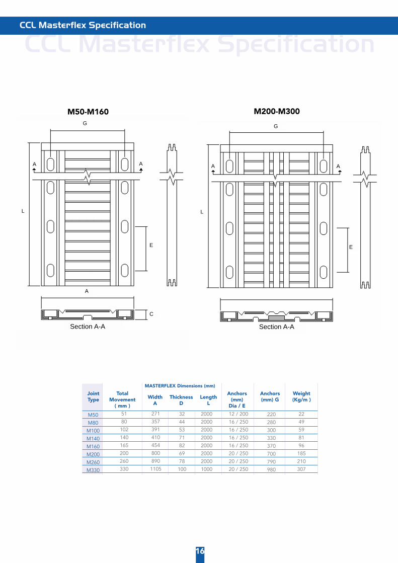
MASTERFLEX Dimensions (mm)
TotalMovement
( mm )
CCL Masterflex Specification CCL Masterflex Specification
16
M50
M80
M100
M140
M160
M200
M260
M330
2000
2000
2000
2000
2000
2000
2000
1000
51
80
102
140
165
200
260
330
271
357
391
410
454
800
890
1105
32
44
53
71
82
69
78
100
12 / 200
16 / 250
16 / 250
16 / 250
16 / 250
20 / 250
20 / 250
20 / 250
22
49
59
81
96
185
210
307
220
280
300
330
370
700
790
980
Joint Type
Anchors(mm)
Dia / E
Anchors(mm) G
Weight(Kg/m )Width
AThickness
DLength
L
M50-M160 M200-M300
Section A-ASection A-A
A
C
E E
G
A A AA
G
L L

Expansion Joint Selector The selection of the type of MASTERFLEX joint depends on the calculated movement of thestructure. However, when the movement direction is neither parallel or perpendicular to thedirection of the joint, the choice of joint type can be easily obtained using the following graph.
ExampleVx = ±48mm β =30º= required type = M140
Expansion Joint Selector
17
Movement in theDirection of Movement (Vx)
Join
t Typ
e
M330
M200
M140
M80
M50
M260
M160
M100
±130
±120
±110
±100
±90
±80
±70
±60
±50
±40
±30
±20
±10±10
±20
±30
±40
±50
β
±60
±70±80
±90
±10
±20
±30
±40
±50
±60
±70
±80
±90
Transversal Axis of Structure
Angle B
Long
itudin
al Axis
of M
ASTERFLEX
Long
itudi
nal A
xis
of S
truc
ture
= D
irect
ion
of M
ovem
ent

CCL Masterflex Installation
18
CCL Masterflex Installation
STEP 1
STEP 2
STEP 3
STEP 4
STEP 5
STEP 6
STEP 7
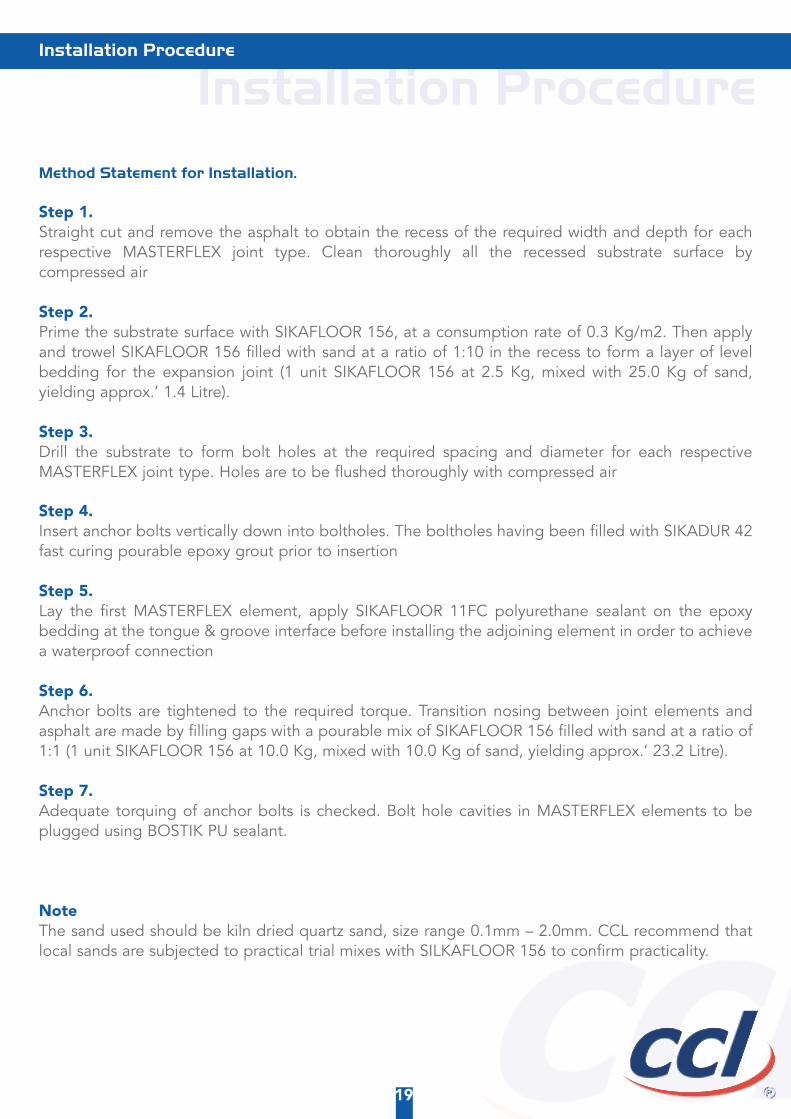
Installation Procedure Method Statement for Installation.
Step 1. Straight cut and remove the asphalt to obtain the recess of the required width and depth for eachrespective MASTERFLEX joint type. Clean thoroughly all the recessed substrate surface bycompressed air
Step 2. Prime the substrate surface with SIKAFLOOR 156, at a consumption rate of 0.3 Kg/m2. Then applyand trowel SIKAFLOOR 156 filled with sand at a ratio of 1:10 in the recess to form a layer of levelbedding for the expansion joint (1 unit SIKAFLOOR 156 at 2.5 Kg, mixed with 25.0 Kg of sand,yielding approx.’ 1.4 Litre).
Step 3. Drill the substrate to form bolt holes at the required spacing and diameter for each respectiveMASTERFLEX joint type. Holes are to be flushed thoroughly with compressed air
Step 4. Insert anchor bolts vertically down into boltholes. The boltholes having been filled with SIKADUR 42fast curing pourable epoxy grout prior to insertion
Step 5. Lay the first MASTERFLEX element, apply SIKAFLOOR 11FC polyurethane sealant on the epoxybedding at the tongue & groove interface before installing the adjoining element in order to achievea waterproof connection
Step 6. Anchor bolts are tightened to the required torque. Transition nosing between joint elements andasphalt are made by filling gaps with a pourable mix of SIKAFLOOR 156 filled with sand at a ratio of1:1 (1 unit SIKAFLOOR 156 at 10.0 Kg, mixed with 10.0 Kg of sand, yielding approx.’ 23.2 Litre).
Step 7. Adequate torquing of anchor bolts is checked. Bolt hole cavities in MASTERFLEX elements to beplugged using BOSTIK PU sealant.
NoteThe sand used should be kiln dried quartz sand, size range 0.1mm – 2.0mm. CCL recommend thatlocal sands are subjected to practical trial mixes with SILKAFLOOR 156 to confirm practicality.
19
Installation Procedure

Telephone: +44 (0)113 270 1221 Fax: +44 (0)113 277 8977
Postal Address: Unit 4, Park 2000 Millennium Way, Westland Road, Leeds, LS11 5AL, EnglandEmail: [email protected] Website: www.cclstressing.com