Embed Size (px)
Citation preview
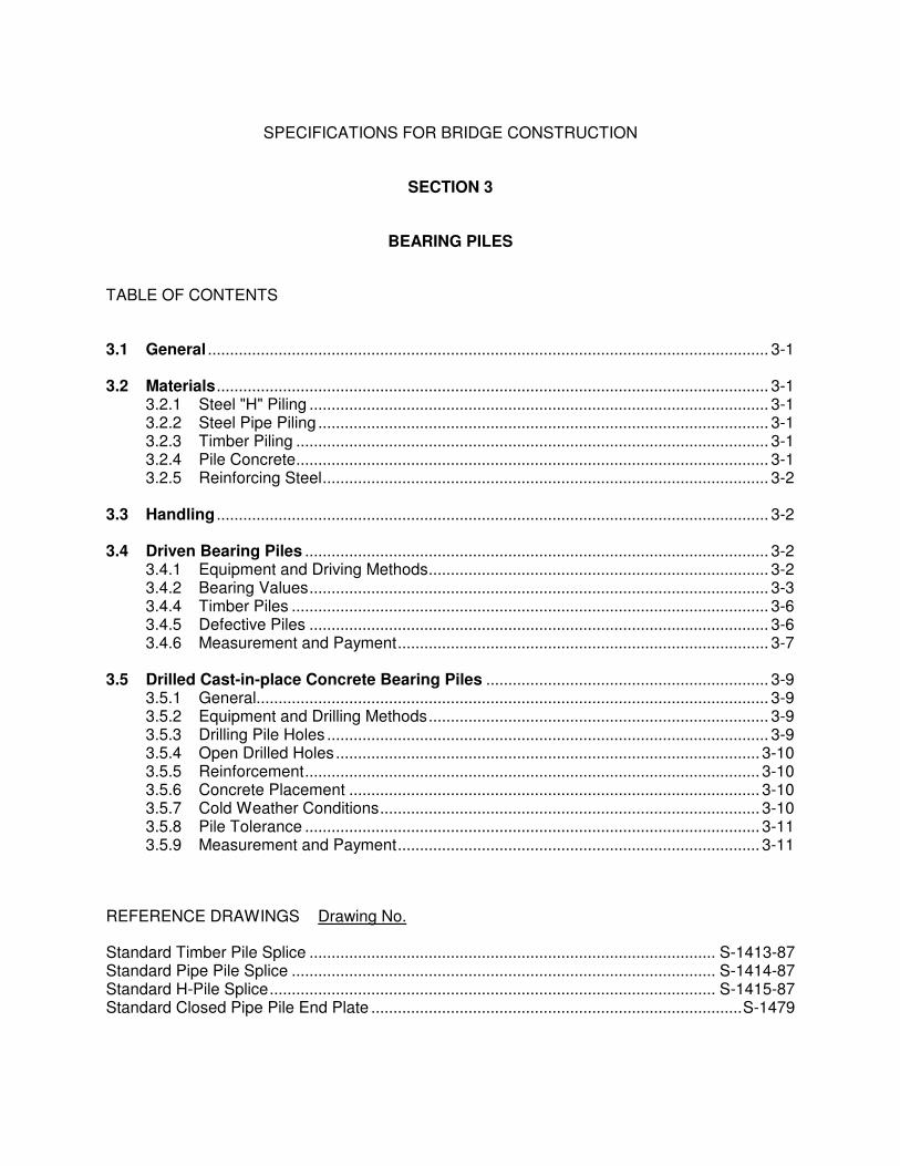
SPECIFICATIONS FOR BRIDGE CONSTRUCTION
SECTION 3
BEARING PILES
TABLE OF CONTENTS
3.1 General ............................................................................................................................... 3-1
3.2 Materials............................................................................................................................. 3-1 3.2.1 Steel "H" Piling ........................................................................................................ 3-1 3.2.2 Steel Pipe Piling ...................................................................................................... 3-1 3.2.3 Timber Piling ........................................................................................................... 3-1 3.2.4 Pile Concrete........................................................................................................... 3-1 3.2.5 Reinforcing Steel..................................................................................................... 3-2
3.3 Handling ............................................................................................................................. 3-2
3.4 Driven Bearing Piles ......................................................................................................... 3-2 3.4.1 Equipment and Driving Methods............................................................................. 3-2 3.4.2 Bearing Values........................................................................................................ 3-3 3.4.4 Timber Piles ............................................................................................................ 3-6 3.4.5 Defective Piles ........................................................................................................ 3-6 3.4.6 Measurement and Payment.................................................................................... 3-7
3.5 Drilled Cast-in-place Concrete Bearing Piles ................................................................ 3-9 3.5.1 General.................................................................................................................... 3-9 3.5.2 Equipment and Drilling Methods............................................................................. 3-9 3.5.3 Drilling Pile Holes .................................................................................................... 3-9 3.5.4 Open Drilled Holes................................................................................................ 3-10 3.5.5 Reinforcement....................................................................................................... 3-10 3.5.6 Concrete Placement ............................................................................................. 3-10 3.5.7 Cold Weather Conditions...................................................................................... 3-10 3.5.8 Pile Tolerance ....................................................................................................... 3-11 3.5.9 Measurement and Payment.................................................................................. 3-11
REFERENCE DRAWINGS Drawing No.
Standard Timber Pile Splice ............................................................................................ S-1413-87 Standard Pipe Pile Splice ................................................................................................ S-1414-87 Standard H-Pile Splice..................................................................................................... S-1415-87 Standard Closed Pipe Pile End Plate ....................................................................................S-1479

Specifications for Bridge Construction Section 3, Bearing Piles
3 - 1
3.1 General
This specification is for the supply and installation of steel H-piles, plain and galvanized steel pipe piles, timber piles, precast concrete piles, and cast-in-place concrete piles. It includes driven bearing piles, drilled cast-in-place concrete bearing piles, and drilled cast-in-place concrete/steel pipe composite bearing piles.
3.2 Materials
3.2.1 Steel "H" Piling
Steel "H" piling shall meet the requirements of Specification ASTM A36 or CSA G40.21M 300W. Where piling is designated in metric dimensions, imperial equivalent piling will be acceptable. Mill certificates shall be provided to the Consultant for review prior to pile installation.
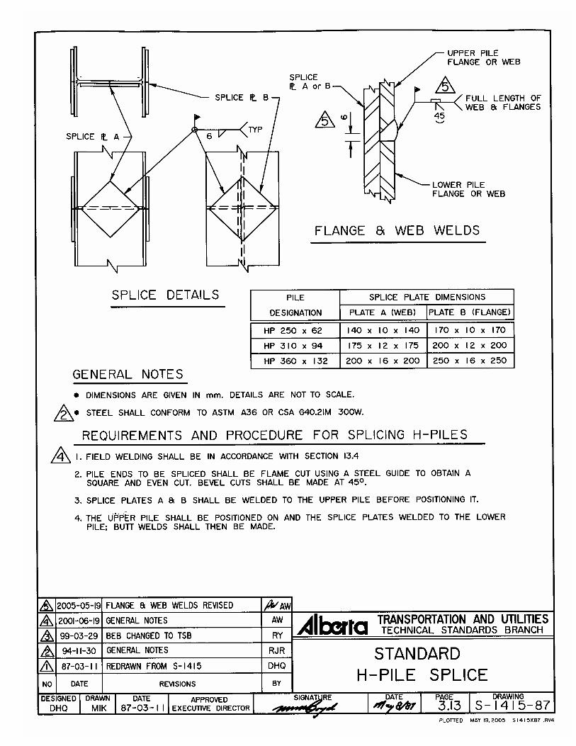
Splice plates shall be fabricated to the dimensions shown on Standard Drawing S-1415 "Standard H-Pile Splice".
3.2.2 Steel Pipe Piling
Steel pipe piling shall meet the requirements of Specification ASTM 252 Grade 2, except that hydrostatic testing is not required. Although piling is designated in metric dimensions, imperial equivalent piling will be acceptable. Mill certificates shall be provided to the Consultant for review prior to pile installation. Some out-of-roundness of the pipe is acceptable provided an acceptable splice can be completed.
Galvanized piling shall be galvanized by the hot dip method, in accordance with CSA Standard G164.
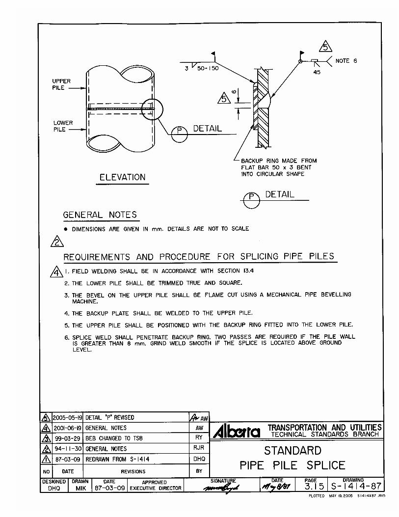
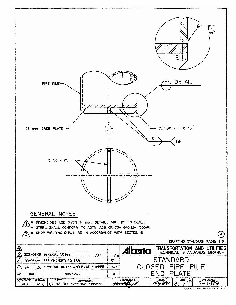
Splice backup rings and closed pipe pile end plates shall be fabricated as shown on Standard Drawing S-1414 "Standard Pipe Pile Splice" and Standard Drawing 1479 "Standard Closed Pipe Pile End Plate".
3.2.3 Timber Piling
Treated timber piling shall be fir or pine, and untreated timber piling shall be fir, spruce, pine or a species that is equal to or better as determined by the Consultant. Timber piling shall conform to Section 23 - �Dimensional Structural Lumber and Piling�, and shall be of the length specified on the drawings.
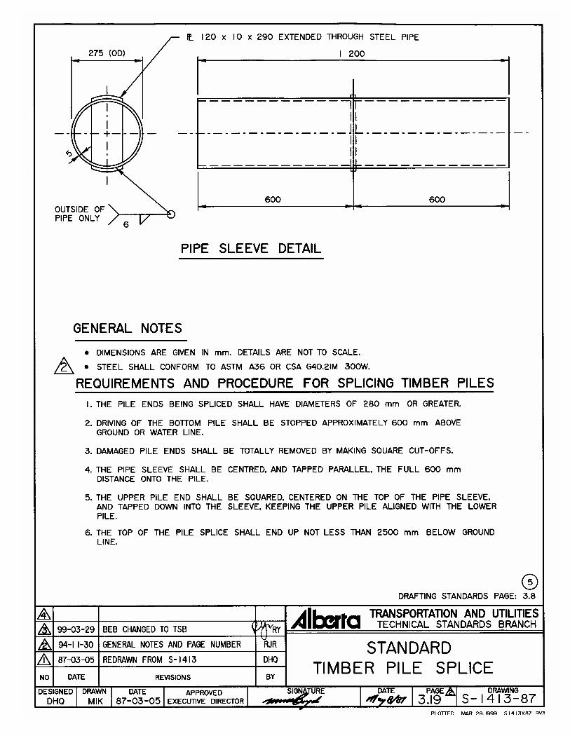
Timber pile splices shall be fabricated as shown on Standard Drawing S-1413 "Standard Timber Pile Splice".
3.2.4 Pile Concrete
Concrete shall meet the requirements of Pile Concrete as specified in Section 4 "Cast-In-Place Concrete".
Specifications for Bridge Construction Section 3, Bearing Piles
3 - 2
3.2.5 Reinforcing Steel
Steel reinforcement incorporated in the pile concrete shall meet the requirements specified in Section 5 "Reinforcing Steel".
3.3 Handling
Piling shall be handled, hauled and stored in a manner that avoids damage to the piling materials. Loading and unloading shall be by crane, loader or other appropriate hoisting equipment.
Care shall be taken in order to prevent damaging the galvanized surface on galvanized piling. Fabric slings, wood blocking or other approved methods shall be used to support and separate galvanized piling when handling, hauling or storing. Piling on which the galvanized coating has been damaged shall be replaced or repaired as determined by the Consultant, at the Contractor's cost. Where repair of damaged galvanizing is required, the repair shall be by metallizing in conformance with ASTM A780, Method A3, to a thickness of 180 �m.
Special care shall be taken to avoid breaking through the surface treatment of treated piles, and cant-hooks, dogs, or pike poles shall not be used. Cuts or breaks in the surface of treated piles shall be given three brush coats of creosote oil of approved quality, and creosote oil shall be poured into all bolt holes.
3.4 Driven Bearing Piles
3.4.1 Equipment and Driving Methods
All pile driving equipment, driving methods and procedures shall be reviewed by the Consultant before any driving is started. Acceptable driving equipment includes diesel hammers, vibratory hammers, driving frames or other equipment as may be required by the Consultant. The use of multi-component drop hammers will not be permitted under any circumstances. The use of gravity hammers will not be permitted except when the required bearing value is less than 350 kN, and the Consultant deems the gravity hammer and leads to be suitable. Where the use of a gravity hammer is acceptable, the Contractor shall furnish to the Consultant acceptable proof of its weight including the weight of the follower.
The driving of piles with driving extensions shall be avoided if practicable, and shall be done only under written permission of the Consultant. When driving extensions are used, one pile from each group of 10 shall be a long pile driven without extensions, and shall be used as a test pile to determine the average bearing power of the group. For the special types of piling, driving heads, mandrels, or other devices in accordance with the manufacturer's recommendations shall be provided so that the pile may be driven without damage and without unnecessary trimming.
The Contractor shall take adequate precautions to ensure that the piles are in proper alignment, including the use of installation frames, fixed leads or other means as are necessary. The method of alignment and maintaining alignment shall meet the acceptance of the Consultant.
For pile installation monitoring purposes, the Contractor shall paint markings on each pile at 0.25 m intervals, with a label at each 1.0 m interval, starting from the toe of the pile.
Specifications for Bridge Construction Section 3, Bearing Piles
3 - 3
Piles shall be driven with a variation of not more than 20 mm per metre from the vertical or from the batter shown on the drawings, except that piles in exposed bents shall not be out of position at the ground line by more than 50 mm and shall not be out of position more than 25 mm in the pile cap. Foundation piles shall not be out of the position shown on the drawings more than 150 mm after driving.
3.4.2 Bearing Values
The piles shall all be driven to the tip elevations shown on the drawings, or lower, to achieve the required stability and specified minimum bearing capacity. The pile bearing capacities shall be estimated by the Bearing Formulas of this Specification.
After the pile driving operations have been started, the Department and Consultant may revise the required pile tip elevations, if necessary, using the pile driving data and the Bearing Formulas as a guide.
In the event pile tip elevations are not given on the drawings, the pile bearing capacities shall be estimated by any or all of the methods outlined under Bearing Formulas, Loading Tests, or Test Piles, as determined by the Consultant.
In the case of friction piles, the piles shall be driven to the tip elevations shown on the Drawings, or lower, in order to achieve the required stability and design load carrying capacity.
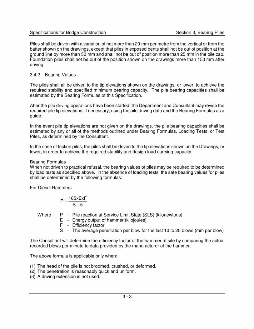
Bearing Formulas When not driven to practical refusal, the bearing values of piles may be required to be determined by load tests as specified above. In the absence of loading tests, the safe bearing values for piles shall be determined by the following formulas:
For Diesel Hammers
5SxExF165
P+
= �
Where P - Pile reaction at Service Limit State (SLS) (kilonewtons) E - Energy output of hammer (kilojoules) F - Efficiency factor S - The average penetration per blow for the last 10 to 20 blows (mm per blow)
The Consultant will determine the efficiency factor of the hammer at site by comparing the actual recorded blows per minute to data provided by the manufacturer of the hammer.
The above formula is applicable only when:
(1) The head of the pile is not broomed, crushed, or deformed. (2) The penetration is reasonably quick and uniform. (3) A driving extension is not used.
Specifications for Bridge Construction Section 3, Bearing Piles
3 - 4
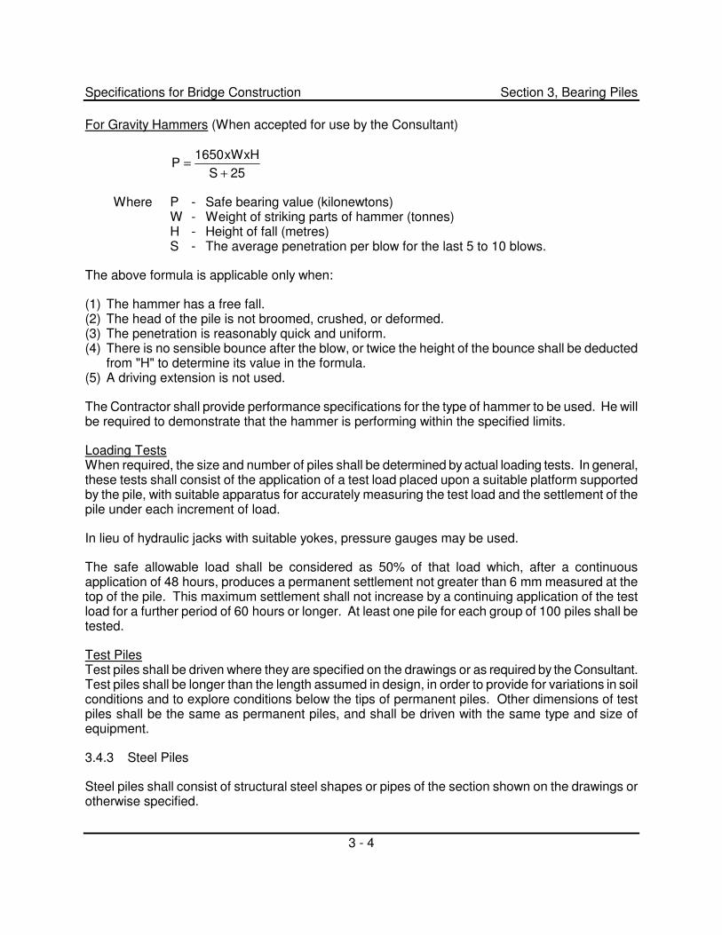
For Gravity Hammers (When accepted for use by the Consultant)
25SxWxH1650
P+
=
Where P - Safe bearing value (kilonewtons) W - Weight of striking parts of hammer (tonnes) H - Height of fall (metres) S - The average penetration per blow for the last 5 to 10 blows.
The above formula is applicable only when:
(1) The hammer has a free fall. (2) The head of the pile is not broomed, crushed, or deformed. (3) The penetration is reasonably quick and uniform. (4) There is no sensible bounce after the blow, or twice the height of the bounce shall be deducted
from "H" to determine its value in the formula. (5) A driving extension is not used.
The Contractor shall provide performance specifications for the type of hammer to be used. He will be required to demonstrate that the hammer is performing within the specified limits.
Loading Tests When required, the size and number of piles shall be determined by actual loading tests. In general, these tests shall consist of the application of a test load placed upon a suitable platform supported by the pile, with suitable apparatus for accurately measuring the test load and the settlement of the pile under each increment of load.
In lieu of hydraulic jacks with suitable yokes, pressure gauges may be used.
The safe allowable load shall be considered as 50% of that load which, after a continuous application of 48 hours, produces a permanent settlement not greater than 6 mm measured at the top of the pile. This maximum settlement shall not increase by a continuing application of the test load for a further period of 60 hours or longer. At least one pile for each group of 100 piles shall be tested.
Test Piles Test piles shall be driven where they are specified on the drawings or as required by the Consultant. Test piles shall be longer than the length assumed in design, in order to provide for variations in soil conditions and to explore conditions below the tips of permanent piles. Other dimensions of test piles shall be the same as permanent piles, and shall be driven with the same type and size of equipment.
3.4.3 Steel Piles
Steel piles shall consist of structural steel shapes or pipes of the section shown on the drawings or otherwise specified.
Specifications for Bridge Construction Section 3, Bearing Piles
3 - 5
When pipe piles are to be driven closed-ended, one section of pipe for each proposed pile shall be supplied with the end-plate welded-on, in conformity with Standard Drawing S-1479 "Standard Closed Pipe Pile End Plate" included with these Specifications.
When pipe piles are to be driven open-ended and the interiors cleaned out, a power screw rotary auger, acceptable to the Consultant shall be used to remove the required material. All loose material and all material adhering to the walls of the piles shall be removed.
The total energy developed by the hammer shall be sufficient to achieve the required bearing value or tip elevation, but in no case shall the total energy developed be less than 35 kJ per blow.
The head shall be cut squarely and a driving cap or follower shall be provided to hold the axis of the pile in line with the axis of the hammer. The follower shall be of adequate dimensions to allow driving the pile without trimming or reducing the cross-section of the pile. When damage or buckling is evident at the driving end of the pile in order to obtain the desired bearing capacity or penetration of the pile, the Contractor shall at his own expense reinforce the driving end of the piling, or provide other suitable equipment or procedures, to prevent such damage.
Piles shall be cut off level at the required elevation. If capping is required, the connection shall be made according to details shown on the drawings.
The Contractor shall supply and secure temporary caps on all open pipe piles or drilled holes.
3.4.3.1 Steel Pile Splices
When splicing, the Contractor shall employ whatever means necessary to match out-of-round piling. Exposed pile splices shall be avoided. Refer to Standard Drawing S-1415 "Standard H-Pile Splice" and Standard Drawing S-1414 "Standard Pipe Pile Splice" included with these Specifications.
Where the upper portions of piling are specified to be galvanized, excess piling shall be removed from the ungalvanized portion of the piling to ensure that the galvanized portion extends to the elevation shown on the drawings. Splicing within the galvanized portion of the piling shall be avoided; however if splicing becomes necessary due to unforeseen circumstances, the damage galvanized area shall be metallized by the Contractor at his cost.
The Contractor shall advise his staff and his welding personnel of the hazardous fumes which are generated during welding or cutting of the galvanized steel.
3.4.3.2 Testing by the Contractor
The Contractor shall arrange to have a minimum of 20% of all full penetration splice welds inspected for piles with 600 mm or larger in diameter either by ultrasonic testing or radiographic inspection methods. The Consultant will randomly select the splices for inspection. The NDT shall be done by a company certified to CAN/CSA W178.1. Ultrasonic and radiographic testing technicians shall be certified to Level II of CGSB. A copy of test results shall be provided to the Consultant for his review within three days of the inspection. The Consultant may require additional inspection if deemed necessary.
Specifications for Bridge Construction Section 3, Bearing Piles
3 - 6
All costs associated with non-destructive inspection of welds shall be the responsibility of the Contractor.
3.4.4 Timber Piles
Gravity hammers when accepted for driving timber piles shall weigh not less than 1.5 t, and in no case shall the weight of the hammer be less than the combined weight of driving head and pile. The fall shall be so regulated as to avoid injury to the piles and in no case shall exceed 3 m. When a diesel hammer is used total energy developed by the hammer shall be not less than 15 kJ per blow.
The pile head shall be cut squarely and a driving cap or follower shall be provided to hold the axis of the pile in line with the axis of the hammer. The follower shall be of adequate dimensions to allow driving the pile without in any way trimming or reducing the cross-section of the pile.
The Contractor shall provide and install collars, bands, or other devices to prevent timber piles from splitting or brooming.
When the area of the head of any timber pile is greater than that of the face of the hammer, a suitable follower shall be provided to distribute the blow of the hammer throughout the cross-section of the pile and thus avoid splitting or shattering the pile.
Timber piles shall be pointed where soil conditions require it. When necessary, the piles shall be shod with metal shoes, supplied by the Contractor, of a design satisfactory to the Consultant, the points of the piles being carefully shaped to secure an even and uniform bearing on the shoes.
Full length piles shall be used where practicable. In exceptional circumstances splicing of piles may be permitted. The method of splicing shall be as shown on the drawings or as reviewed and accepted by the Consultant. Refer to Standard Drawing S-1413 "Standard Timber Pile Splice" included with these Specifications.
The tops of all piling shall be trimmed to a true plane at the elevation shown on the drawings or fixed by the Consultant. Piles which support timber caps or grillage shall be sawed to conform to the plane of the bottom of the super-imposed structure. In general, the length of pile above the elevation of cut-off shall be sufficient to permit the complete removal of all material injured by driving, but piles driven to very nearly the cut-off elevation shall be carefully trimmed and freed of all "broomed", splintered or otherwise injured material.
3.4.5 Defective Piles
The procedure incident to the driving of piles shall not subject them to excessive and undue abuse producing deformation of the steel, injurious splitting, splintering and brooming of the wood, or crushing and spalling of the concrete. Manipulation of piles to force them into proper position, considered by the Consultant to be excessive, will not be permitted. Piles damaged by improper driving, or driven out of proper location, or driven below the cut-off elevation, shall be corrected, at the Contractor's expense, by one of the following methods accepted by the Consultant:
(a) The piles shall be withdrawn and replaced by new and, if necessary, longer piles, or
Specifications for Bridge Construction Section 3, Bearing Piles
3 - 7
(b) Replacement piles shall be driven adjacent to defective or low piles, or
(c) The piles shall be spliced or built up, as otherwise provided herein, or a sufficient portion of the footing extended to properly embed the piles. Timber piles shall not be spliced without specific permission of the Consultant. All piles, pushed up by the driving of adjacent piles or by any other cause, shall be driven down again.
In case the required penetration and bearing capacity are not obtained, the contractor shall provide a hammer of greater energy, as applicable, or when accepted by the Consultant/Department, resort to pre-drilling. This will be considered incidental to the work of achieving acceptable penetration and bearing capacity, and not claimable as extra work.
3.4.6 Measurement and Payment
Supply of Piling Payment for Supply of Piling will be made on the basis of the unit price per metre bid for each type of piling supplied, which price shall include full compensation for the cost of furnishing and delivering the material to site. The unit prices shall include full compensation for the cost of all labour, tools, equipment and other necessary or incidental costs of handling, loading and hauling the piling.
The number of metres of piling to be paid for shall be the total number of metres acceptably driven and remaining in the completed structure. Where portions of steel piling are specified to be galvanized, only the lengths requiring galvanizing will be included in supply of galvanized steel piling. All steel piling below the level of the galvanized piling length shown on the drawings will be included in supply of plain steel piling.
Re-stocking Steel Piling When quantities of plain Steel Pipe or H Piles are reduced by 15% or less due to conditions beyond the Contractor's control, the Department will reimburse the �re-stocking� costs for 6.0 metre lengths or longer, incurred by the supplier to the Contractor.
The Contractor shall present vouchers giving details as to dates, quantities, rates, third party invoices, and such other supporting documentation to the Consultant. Payment will be made on the cost of �re-stocking� and based on the invoices excluding labour burden, overhead and profit.
Pile Set-up Payment for Pile Set-up will be made on the basis of the unit price per pile bid, which price shall include the expense and time to set the equipment over the pile, ready to commence driving. Payment will be made only for piles acceptably driven as determined by the Consultant.
Pile Driving Payment for Pile Driving will be made on the basis of the unit price per metre bid, which price shall include full compensation for the cost of furnishing all labour, tools, and equipment, and other necessary or incidental costs of handling, driving, splicing, cutting off piles, reinforcement of pile heads and all other incidental work connected therewith. It shall also include full compensation for all drilling, blasting, splice plates, splice rings, or other work or materials necessary to obtain the required penetration or bearing values of piles.
Specifications for Bridge Construction Section 3, Bearing Piles
3 - 8
The number of metres to be paid for shall be the total number of metres of piling acceptably driven and remaining in the completed structure.
Pile Tip Reinforcement When the Contract contains a bid item for Pile Tip Reinforcement, payment will be made on the basis of the unit price bid, which price shall include full compensation for all labour, materials, equipment, tools and all incidentals necessary to complete the work.
Pile Splicing When the Contract contains a bid item for Pile Splicing, piles which penetrate in excess of 20% from the designed tip elevation, splicing will be paid for at the assigned unit price for Pile Splicing and will include all labour, materials, equipment, tools and incidentals necessary to complete the work. Only one splice for each additional length of pile, up to twelve metres, will be paid for.
Pile Splicing When the Contract contains a bid item for Pile Splicing, piles which penetrate in excess of 20% from the designed tip elevation, splicing will be paid for at the assigned unit price for Pile Splicing and will include all labour, materials, equipment, tools and incidentals necessary to complete the work. Only one splice for each additional length of pile, up to twelve metres, will be paid for.
Pile Concrete Pile Concrete shall be measured and paid for in accordance with Section 4 - "Cast-In-Place Concrete".
Reinforcing Steel Reinforcing Steel incorporated in the piling will be paid for in accordance with Section 5 - "Reinforcing Steel".
Loading Tests Payment for Loading Tests shall include the cost of all material, equipment and labour incidental to making the loading test or tests as determined by the Consultant, or as specified in the special provisions. Payment will be made on the basis of the contract price for pile loading tests, or, in the absence of such a price, will be made as specified for Extra Work.
Test Piles Test piles retained in the structure will be paid for at the bid price of other piling used.
If, however, piling is not used in the structure, the test piles will be paid for as Extra Work, due to consideration being given to the cost of bringing the pile driver to the site and removing it from the work.
Specifications for Bridge Construction Section 3, Bearing Piles
3 - 9
3.5 Drilled Cast-in-place Concrete Bearing Piles
3.5.1 General
In addition to drilled cast-in-place concrete bearing piles this section shall include drilled cast-in-place concrete/steel pipe composite bearing piles. The work shall include drilling and belling the holes, as required, supplying and placing the steel pipe and reinforcing steel, and supplying, placing, protecting and curing the concrete.
3.5.2 Equipment and Drilling Methods
Due to the nature of the work, the Department requires that the drilling subcontractor have adequate equipment and a proven record of competence in this work.
All pile drilling equipment, drilling methods, and procedures shall be reviewed by the Consultant before drilling is started. Unless otherwise specified only powered screw rotary type augers will be acceptable.
The Contractor shall not proceed with the installation of further piling, if for any reason the quality of the adjacent piling is compromised due to the effects of vibration or other reasons.
3.5.3 Drilling Pile Holes
The drilled pile holes shall be stabilized and sealed by means of temporary casings or other methods to prevent the possible collapse of the pile holes or ingress of water. The Contractor shall make every attempt necessary to obtain "dry" pile holes prior to placing the pile concrete.
Temporary casing, if used in drilling operations, shall be removed from the hole as pile concrete is being poured. The bottom of the casing shall be maintained below the top of the concrete during withdrawal and pouring operations unless otherwise permitted by the Consultant. Separation of the concrete during withdrawal operations shall be avoided by hammering or otherwise vibrating the casing.
The elevations shown on the drawings of the bottoms of the pile holes shall be considered approximate only, and the Department and Consultant may order further drilling as necessary to secure satisfactory bearing of the piles.
Where belling of the piles is specified, belling shall proceed only after the pile hole has been drilled to an elevation acceptable to the Consultant.
The walls and bottoms of the pile holes shall be cleaned to remove all loose and extraneous material. The Contractor shall determine if any gas is present in the pile holes and shall provide whatever means and equipment necessary to ensure a safe work site. Pile reinforcement and pile concrete shall not be placed without the acceptance of the pile holes by the Consultant.
Specifications for Bridge Construction Section 3, Bearing Piles
3 - 10
3.5.4 Open Drilled Holes
The Contractor shall be responsible for covering all open drilled holes on the site until the time they are filled with concrete or otherwise properly backfilled. The covers shall be of adequate strength and securely fitted so that machinery and workmen are protected against cave-in and surface water is prevented from running into the pile hole.
3.5.5 Reinforcement
Steel reinforcement shall be fabricated in the sizes and to the dimensions shown on the drawings and shall be placed, centered and braced in the pile hole to the acceptance of the Consultant.
Particular care shall be taken in locating projecting "column dowel bars", to a tolerance not exceeding 10 mm in any direction, and pouring will not be permitted until the Consultant is satisfied that adequate provisions have been made.
Adequate "shoes" or spacers shall be firmly anchored to the reinforcement to ensure the reinforcement is kept centered in the concrete.
3.5.6 Concrete Placement
When the reinforcement has been acceptably placed, concrete shall be immediately deposited in the pile hole. The concrete shall be "Pile Concrete" and the provisions of Section 4 - "Cast-In-Place Concrete" shall apply.
Suitable forms shall be used to maintain the specified dimensions of concrete piles above ground level.
3.5.7 Cold Weather Conditions
In cold weather, which shall be considered to exist if nighttime low temperatures are expected to be below 0�C, heated concrete shall be used. Such concrete shall have a temperature of between 15�C and 25�C when placed.
When the ground against which pile concrete is placed is below -5�C, the concrete shall be protected from heat loss. The pile boring shall be made oversize down to the depth of 2 m, and the concrete shall be poured in an insulated form. Concrete at the top of the pile is to be insulated. After four days the form and insulation may be removed, and the space is to be backfilled immediately with compacted non-granular fill or lean concrete to the elevation of top of pile.
In a region where the ground temperature is above -10�C but below -5�C, the hole may be bored 100 mm diameter oversize, and filled directly with pile concrete, as an alternative to the procedure described above. Concrete at the top of the pile is to be insulated.
If the top of the pile extends above the existing ground surface, in cold weather, it is to be adequately protected from the cold for a period long enough to ensure proper curing.
Specifications for Bridge Construction Section 3, Bearing Piles
3 - 11
3.5.8 Pile Tolerance
Piles shall be accurately located, and shall be installed plumb or at the batter specified on the drawings. The maximum tolerance allowed shall be 50 mm for variation off the centre of any pile at the cut-off elevation, and no pile shall be out of plumb or specified batter by more than 20 mm per metre. Any pile out of centre or plumb beyond the tolerances specified shall be corrected at the Contractor's expense.
3.5.9 Measurement and Payment
Drill Rig Set-up Payment for Drill Rig Set-up will be made on the basis of the unit price per pile bid which shall include full compensation for the cost to set up the drilling equipment over the pile location ready to commence drilling, and the cost to supply, install and remove temporary casing as required. Payment will be made only for piles acceptably constructed, as determined by the Consultant.
Pile Installation Payment for Pile Installation will be made on the basis of the unit price per lineal metre bid which shall include full compensation for the cost of supplying all materials including piling, drilling, dewatering and cleaning out the holes to the dimensions shown, removal and disposal of the augered material, detection and purging of any gas hazard, and providing safe inspection access. The quantity to be paid for Pile Installation shall be the number of lineal metres required to install the piling in accordance with the drawings and specifications (measured from the pile tip to the underside of pile/pier cap). Drilling will be considered as part of pile installation and no separate or additional payment will be made.
Pile Concrete Pile Concrete will be measured and paid for in accordance with Section 4 "Cast-In-Place Concrete".
Reinforcing Steel Reinforcing Steel incorporated in the piling will be paid for in accordance with Section 5 "Reinforcing Steel".

�
�

�
�
�
�

�
�
�
�

�
�
�
�

�
�