Embed Size (px)
Citation preview

BRIDGE BASICSBRIDGE BASICSInformation SheetsBeam Bridges . . . . . . . . . . . . . . . . . . . . . . . . . . . . . . . . . . . . . . . . . . . . . . . . . . . . . . . . . . . . . . . . . . . . . . . . . .29Arch Bridges . . . . . . . . . . . . . . . . . . . . . . . . . . . . . . . . . . . . . . . . . . . . . . . . . . . . . . . . . . . . . . . . . . . . . . . . . . .30Truss Bridges . . . . . . . . . . . . . . . . . . . . . . . . . . . . . . . . . . . . . . . . . . . . . . . . . . . . . . . . . . . . . . . . . . . . . . . . . . .31Suspension Bridges . . . . . . . . . . . . . . . . . . . . . . . . . . . . . . . . . . . . . . . . . . . . . . . . . . . . . . . . . . . . . . . . . . . . .32Cable-Stayed Bridges . . . . . . . . . . . . . . . . . . . . . . . . . . . . . . . . . . . . . . . . . . . . . . . . . . . . . . . . . . . . . . . . . . . .33“Don‘t Lose, Reuse” Supply Request Sheet . . . . . . . . . . . . . . . . . . . . . . . . . . . . . . . . . . . . . . . . . . . . . . . . . . .49
Student WorksheetsBridge Investigation Worksheets . . . . . . . . . . . . . . . . . . . . . . . . . . . . . . . . . . . . . . . . . . . . . . . . . . . . . . . .50-54
Beam Bridges . . . . . . . . . . . . . . . . . . . . . . . . . . . . . . . . . . . . . . . . . . . . . . . . . . . . . . . . . . . . . . . . . . . . . . .50Arch Bridges . . . . . . . . . . . . . . . . . . . . . . . . . . . . . . . . . . . . . . . . . . . . . . . . . . . . . . . . . . . . . . . . . . . . . . .51Truss Bridges . . . . . . . . . . . . . . . . . . . . . . . . . . . . . . . . . . . . . . . . . . . . . . . . . . . . . . . . . . . . . . . . . . . . . . .52Suspension Bridges . . . . . . . . . . . . . . . . . . . . . . . . . . . . . . . . . . . . . . . . . . . . . . . . . . . . . . . . . . . . . . . . .53Cable-Stayed Bridges . . . . . . . . . . . . . . . . . . . . . . . . . . . . . . . . . . . . . . . . . . . . . . . . . . . . . . . . . . . . . . . .54
Engineering Bridges Scenario Worksheets . . . . . . . . . . . . . . . . . . . . . . . . . . . . . . . . . . . . . . . . . . . . . . . . .55-60Materials Testing Worksheet . . . . . . . . . . . . . . . . . . . . . . . . . . . . . . . . . . . . . . . . . . . . . . . . . . . . . . . . . . . .73-74Pasta Bridge Building Evaluation Sheet . . . . . . . . . . . . . . . . . . . . . . . . . . . . . . . . . . . . . . . . . . . . . . . . . . . . . .80The Long and Short of American Bridges Worksheet . . . . . . . . . . . . . . . . . . . . . . . . . . . . . . . . . . . . . . . . .84-86Bridge Research Guide Worksheet . . . . . . . . . . . . . . . . . . . . . . . . . . . . . . . . . . . . . . . . . . . . . . . . . . . . . . .87-88
Instructions for Card Bridge ModelsArch BridgeBeam BridgeCable-Stayed BridgeSuspension BridgeTruss Bridge
Bridge Type PostersArch Bridges Beam Bridges Cable-Stayed Bridges Suspension Bridges Truss Bridges
Curriculum Page Number
The Bridge Basics Program Kit has been produced in partnership with the Construction IndustryRound Table (CIRT). For more information about CIRT, visit www.cirt.org.

© 2005 National Building Museum | Bridge Essentials 29
Walter B. Jones Bridge, Hyde County, NC, completed 1981, courtesy North Carolina Department of Traffic
roadway
live load
pier
beam
distance
compression
tension
pierpier
spanspan
Beam Bridges
n Pros and Cons of Beam Bridges n
n Pros: Easy to build; inexpensive relative to otherbridge types; used widely in urban and rural settings
n Cons: Limited span; large ships or heavy boat trafficcannot pass underneath; design generally not consid-ered very interesting or eye-catching
n n Compression and Tension n n
n Compression: As live loads, such as cars and trucks,travel across the bridge, the force of compressionacts on the top of the roadway and passes downinto the piers.
n Tension: The force of tension acts on the undersideof the roadway, which is pulled apart by the live loadspressing down on the top of the roadway.
B eam bridges are the oldest known bridges and tend to be the simplest to design and build. Roughly half of all bridgesin the United States are beam bridges. They consist of vertical piers and horizontal beams. A beam bridge’s strength
depends on the strength of the roadway and can be increased by adding additional piers. While beam bridges can be quitelong, the span, or distance between adjacent piers, is usually small.
BRIDGE BRAG
It’s the loooooooonnnnnnngest bridge in the world, and it’s a beam bridge! The Lake Pontchartrain Causeway in Louisiana isapproximately 24 miles long, and its twin spans are supported by more than 9,000 pilings.

Arch Bridges
BRIDGE BRAG
Montgomery Meigs, the architect and engineer of the National Building Museum, also designed the complex Washingtonaqueduct system. It carries water from the Potomac River over the arched Cabin John Bridge in Maryland to two water pro-cessing plants in nearby Washington, D.C. When the bridge was completed in 1863, it was the longest masonry arch in theworld. It held the record for 40 years. The main arch has a span of 220 feet, rising 57 feet above a creek.
n Pros and Cons of Arch Bridges n
n Pros: Wide range of materials can be used; consid-ered attractive; very strong
n Cons: Relatively expensive; typically, designs are limitedto certain sites (e.g., where the ground can supportthe large forces at the base of the arch; where thespan-to-depth ratio of the arch is proportional; orwhere an arch is visually appropriate)
n n Compression and Tension n n
n Compression: The force of compression is greatestat the top of the arch. The abutments press againstthe bottom of the arch, preventing the bases of thearch from being pushed outward.
n Tension: The force of tension is strongest at the bot-tom of the arch and pulls the sides outward. In gener-al, the larger and shallower the arch, the greater theeffects of tension and need for abutment support.
A rch bridges were built by the Romans and have been in use ever since. They are often chosen for their strength andappearance. It is the shape of the arch that gives the bridge its strength, which is reinforced by placing supports, or
abutments, at its base. Arch bridges can be built from various materials, including wood, stone, concrete, and steel. Thefamous Italian artist Leonardo da Vinci once said, “An arch consists of two weaknesses, which, leaning on each other,become a strength.”
Antietam Aqueduct, Savage, MD, completed 1834, courtesy Lawrence Biemiller
30 Bridge Basics | © 2005 National Building Museum
live load
span span
distance
keystonekeystone
abutments abutmentabutment
compression
tensionroadway

© 2005 National Building Museum | Bridge Essentials 31
Truss Bridges
n Pros and Cons of Truss Bridges n
n Pros: Very strong; frequently used as a draw bridge oras an overpass for railroad trains
n Cons: Difficult to construct; high maintenance; difficultto widen if necessary; generally not considered attractive
n n Compression and Tension n n
n Compression: As traffic pushes down on the road-way, compression acts on the upper horizontal mem-bers of the truss structure.
n Tension: Tension acts on the bottom horizontal mem-bers of the truss structure. The forces of tension andcompression are shared among the angled members.
W ooden truss bridges were used as early as the 1500s, but the first metal one was completed in 1841. They are verystrong and have been used for railroad bridges mainly because of the heavy loads that they can support. A truss, a
rigid support structure that is made up of interlocking triangles, holds up the roadbed and is set between two piers. The tri-angle is used because it is the only shape that is inherently rigid.
George Street Bridge, Aurora, IN, completed 1887, courtesy Indiana Department of Transportation
live loadcompression
tension
pier pier
distance
roadway
trusses
span
BRIDGE BRAG
It’s difficult to see the trusses on some of America’s best-known truss bridges, the covered bridges that were common in therural Northeast. The roofs were not constructed to protect people from severe weather, but to preserve the truss systemitself. Wooden bridges without roofs would last 10 to 15 years, but covering the bridge extended its life to 70 or 80 years.

Suspension Bridges
BRIDGE BRAG
The Tacoma Narrows suspension bridge in Washington State was known as “Galloping Gertie” because it rippled like a rollercoaster. Completed in July 1940, the first heavy storm four months later caused the bridge to break and collapse from wind-induced vibrations. It was replaced by a stiffer bridge, which has proven to be satisfactory.
n Pros and Cons of Suspension Bridges n
n Pros: Span distances up to 7,000 feet; consideredattractive; allow large ships and heavy boat traffic topass underneath
n Cons: Expensive (require a long time and a largeamount of material to build)
n n Compression and Tension n n
n Compression: Traffic pushes down on the roadway,but because it is suspended from the cables, theweight is carried by the cables, which transfer theforce of compression to the two towers.
n Tension: The force of tension is constantly acting onthe cables, which are stretched because the roadwayis suspended from them.
S uspension bridges are strong and can span long distances. One early bridge was designed and built in 1801 in Penn-sylvania. They are expensive because they take a long time to build and require a large amount of material. They are
commonly found across harbors with a lot of boat traffic. The primary elements of a suspension bridge are a pair of maincables stretching over two towers and attached at each end to an anchor. Smaller cables attached to the main cables supportthe roadway.
Golden Gate Bridge, San Francisco, CA, completed 1937, used with permission from The GoldenGate Bridge, Highway and Transportation District, San Francisco, CA, www.goldengatebridge.org
32 Bridge Basics | © 2005 National Building Museum
live load
roadway
cables
anchor
tower
cables
towercompression
tension
anchor
span
distance

© 2005 National Building Museum | Bridge Essentials 33
Cable-Stayed Bridges
n Pros and Cons of Cable-Stayed Bridges n
n Pros: Span medium distances (500–2,800 feet); lessexpensive and faster to build than suspension bridges;considered attractive
n Cons: Typically more expensive than other types ofbridges, except suspension bridges
n n Compression and Tension n n
n Compression: As traffic pushes down on the road-way, the cables, to which the roadway is attached,transfer the load to the towers, putting them in com-pression.
n Tension: The force of tension is constantly acting onthe cables, which are stretched because they areattached to the roadway.
T he first modern cable-stayed bridge was completed in Sweden in 1956. Cable-stayed bridges were created as aneconomical way to span long distances. This bridge’s design and success were made possible as new materials and
construction techniques were developed. Cable-stayed bridges have one or more towers, each of which anchors a set ofcables attached to the roadway.
compression
tension
live load
pylon
distance
roadway
cables
spanspan
live load
BRIDGE BRAG
America’s longest cable-stayed bridge, the Cooper River Bridge in Charleston, South Carolina, opened in summer 2005. It isapproximately 2.5 miles long and 186 feet above the river. The central span between the two towers is 1,546 feet, and thetowers themselves rise 575 feet above the water line.
Fred Hartman Bridge, Baytown/Laporte, TX, completed 1995, courtesy Kevin Stillman, Texas Depart-ment of Transportation
© 2005 National Building Museum | Basic Program 49
Materials to Gather for the Engineering Bridges Lesson
Student’s Name:
STUDENTS:During your upcoming lessons, you will work in groups to create model bridges. Please bring items from hometo use as part of your bridge.
U Paper towel or toilet paper rolls could be used as piers for a truss bridge.
U Oatmeal containers could be transformed into arches for a bridge.
U Narrow ribbons may become the cables on a suspension or cable-stayed bridge.
U Small boxes and egg cartons could be used to create pier, and cars for a bridge.
U Can you think of anything else?
WARNING: Please avoid bringing milk cartons or containers that once held peanuts or peanut butter.
Some people are highly allergic to these items.
Using recycled materials to create bridges in this program helps to preserve the natural environment by promotingreuse of objects, rather than their disposal. Such activities prevent filling landfill sites and polluting our environment.
Other materials needed:
Please bring clean, recycled materials from home by:
“Don’t Lose, Reuse” Supply Request Sheet
Don’t Lose REUSE!
date

LOOK at the beam bridge images on the poster.
TEST the strength of the beam bridge card model, using a stapler or another object of similar size.
ANSWER the questions below, using the images and model.
Bridge Investigation Worksheet:Beam Bridges
Over WHICH obstacles do you commonlyfind beam bridges?
q roads/highways
q canyons/valleys
q creeks/streams
q rivers
q bays
HOW do beam bridges work?
Review the areas of compression and tension.
WHAT are two pros and cons of beambridges?
Pros (positive aspects of the bridge)
1
2
Cons (negative aspects of the bridge)
1
2
WHY do architects and engineers build beam bridges?
q easily span short distances
q span long distances
q sturdy
q easy to build
q engineering challenge
q cost effective
q allow large ships to pass underneath
q appearance
live load
compression live loadtensionKEY
chec
kas
man
yas
are
appr
opria
te
50 Bridge Basics | © 2005 National Building Museum
chec
kas
man
yas
are
appr
opria
te

© 2005 National Building Museum | Basic Program 51
LOOK at the arch bridge images on the poster.
TEST the strength of the arch bridge card model, using a stapler or another object of similar size.
ANSWER the questions below, using the images and model.
Bridge Investigation Worksheet:Arch Bridges
Over WHICH obstacles do you commonlyfind arch bridges?
q roads/highways
q canyons/valleys
q creeks/streams
q rivers
q bays
HOW do arch bridges work?
Review the areas of compression and tension.
WHAT are two pros and cons of archbridges?
Pros (positive aspects of the bridge)
1
2
Cons (negative aspects of the bridge)
1
2
WHY do architects and engineers build arch bridges?
q easily span short distances
q span long distances
q sturdy
q easy to build
q engineering challenge
q cost effective
q allow large ships to pass underneath
q appearance
live load
compression live loadtensionKEY
chec
kas
man
yas
are
appr
opria
te
chec
kas
man
yas
are
appr
opria
te

52 Bridge Basics | © 2005 National Building Museum
LOOK at the truss bridge images on the poster.
TEST the strength of the truss bridge card model, using a stapler or another object of similar size.
ANSWER the questions below, using the images and model.
Bridge Investigation Worksheet:Truss Bridges
Over WHICH obstacles do you commonlyfind truss bridges?
q roads/highways
q canyons/valleys
q creeks/streams
q rivers
q bays
HOW do truss bridges work?
Review the areas of compression and tension.
WHAT are two pros and cons of trussbridges?
Pros (positive aspects of the bridge)
1
2
Cons (negative aspects of the bridge)
1
2
WHY do architects and engineers build truss bridges?
q easily span short distances
q span long distances
q sturdy
q easy to build
q engineering challenge
q cost effective
q allow large ships to pass underneath
q appearance
live load
compression live loadtensionKEY
chec
kas
man
yas
are
appr
opria
te
chec
kas
man
yas
are
appr
opria
te

© 2005 National Building Museum | Basic Program 53
LOOK at the suspension bridge images on the poster.
TEST the strength of the suspension bridge card model, using a stapler or another object of similar size.
ANSWER the questions below, using the images and model.
Bridge Investigation Worksheet:Suspension Bridges
Over WHICH obstacles do you commonlyfind suspension bridges?
q roads/highways
q canyons/valleys
q creeks/streams
q rivers
q bays
HOW do suspension bridges work?
Review the areas of compression and tension.
WHAT are two pros and cons of suspension bridges?
Pros (positive aspects of the bridge)
1
2
Cons (negative aspects of the bridge)
1
2
WHY do architects and engineers build suspension bridges?
q easily span short distances
q span long distances
q sturdy
q easy to build
q engineering challenge
q cost effective
q allow large ships to pass underneath
q appearance
live load
compression live loadtensionKEY
chec
kas
man
yas
are
appr
opria
te
chec
kas
man
yas
are
appr
opria
te

54 Bridge Basics | © 2005 National Building Museum
LOOK at the cable-stayed bridge images on the poster.
TEST the strength of the cable-stayed bridge card model using a stapler or similar size object.
ANSWER the questions below using the images and model.
Bridge Investigation Worksheet:Cable-Stayed Bridges
Over WHICH obstacles do you commonlyfind cable-stayed bridges?
q roads/highways
q canyons/valleys
q creeks/streams
q rivers
q bays
HOW do cable-stayed bridges work?
Review the areas of compression and tension.
WHAT are two pros and cons of cable-stayed bridges?
Pros (positive aspects of the bridge)
1
2
Cons (negative aspects of the bridge)
1
2
WHY do architects and engineers build cable-stayed bridges?
q easily span short distances
q span long distances
q sturdy
q easy to build
q engineering challenge
q cost effective
q allow large ships to pass underneath
q appearance
live loadlive load
compression live loadtensionKEY
chec
kas
man
yas
are
appr
opria
te
chec
kas
man
yas
are
appr
opria
te

Engineering Bridges Scenario 1
Bridge Basics Program Kit | Basic Program | Engineering Bridges Lesson | © 2005 National Building Museum | 55
? WHAT is the problem?
WHO thinks it is a problem?
WHERE does the problem exist?
HOW can the problem be solved? JUSTIFY YOUR SOLUTION.
AS ENGINEERS, you must define the problem described at the right anddetermine which type of bridge best solves it, taking into account site location, forces, and appearance.
n DIRECTIONS n
1. Read the scenario described at the right.
2. Consider the questions below.
3. Sketch your bridge site and the bridge you have selected on the back of this page.
4. Show your drawing to the head engineer (teacher) for final approval.
5. Build a bridge model.
A truss bridge currently spans a deep river
in a large city. There is heavy boat
traffic under the bridge. Automobile traffic
backs up on the bridge whenever it opens
for boats to pass through. Traffic is especially
heavy during rush hour, and commuters are
angry about the constant delays. This is also
an important site in the city, and the citizens
want this bridge to be a symbol for them.
What should the city do?
Engineering Bridges Scenario 2
Bridge Basics Program Kit | Basic Program | Engineering Bridges Lesson | © 2005 National Building Museum | 55
? WHAT is the problem?
WHO thinks it is a problem?
WHERE does the problem exist?
HOW can the problem be solved? JUSTIFY YOUR SOLUTION.
AS ENGINEERS, you must define the problem described at the right anddetermine which type of bridge best solves it, taking into account site location, forces, and appearance.
n DIRECTIONS n
1. Read the scenario described at the right.
2. Consider the questions below.
3. Sketch your bridge site and the bridge you have selected on the back of this page.
4. Show your drawing to the head engineer (teacher) for final approval.
5. Build a bridge model.
A beautiful creek runs through a park in
a big city. The city is planning to build
a highway that will cross the creek. The
highway bridge will need to support heavy
car and truck traffic.The creek is shallow and
does not have boat traffic, although the local
residents fish in it. The people who live near
the creek are afraid that the bridge will be
ugly and negatively impact the scenic beau-
ty of the area. What should the city do?

Bridge Basics Program Kit | Basic Program | Engineering Bridges Lesson | © 2005 National Building Museum | 56
Bridge Basics Program Kit | Basic Program | Engineering Bridges Lesson | © 2005 National Building Museum | 56

Engineering Bridges Scenario 3
Bridge Basics Program Kit | Basic Program | Engineering Bridges Lesson | © 2005 National Building Museum | 57
? WHAT is the problem?
WHO thinks it is a problem?
WHERE does the problem exist?
HOW can the problem be solved? JUSTIFY YOUR SOLUTION.
AS ENGINEERS, you must define the problem described at the right anddetermine which type of bridge best solves it, taking into account site location, forces, and appearance.
n DIRECTIONS n
1. Read the scenario described at the right.
2. Consider the questions below.
3. Sketch your bridge site and the bridge you have selected on the back of this page.
4. Show your drawing to the head engineer (teacher) for final approval.
5. Build a bridge model.
A railroad is being built over a small rural
river.There is limited boat traffic under
the bridge.The trains are very heavy, and the
existing wooden covered bridge will not be
able to hold the weight of the trains. What
should the county do?
Engineering Bridges Scenario 4
Bridge Basics Program Kit | Basic Program | Engineering Bridges Lesson | © 2005 National Building Museum | 57
? WHAT is the problem?
WHO thinks it is a problem?
WHERE does the problem exist?
HOW can the problem be solved? JUSTIFY YOUR SOLUTION.
AS ENGINEERS, you must define the problem described at the right anddetermine which type of bridge best solves it, taking into account site location, forces, and appearance.
n DIRECTIONS n
1. Read the scenario described at the right.
2. Consider the questions below.
3. Sketch your bridge site and the bridge you have selected on the back of this page.
4. Show your drawing to the head engineer (teacher) for final approval.
5. Build a bridge model.
A city with a large population is planning
a bridge that will cross a river.The river
is very deep and wide with a muddy bottom.
The most favorable site for the bridge crosses
a small island in the middle of the river.This
land is currently unpopulated and is home
to wild deer and shore birds.A local environ-
mental group is protesting the bridge because
of the negative impact of traffic and construc-
tion on the island. What should the city do?

Bridge Basics Program Kit | Basic Program | Engineering Bridges Lesson | © 2005 National Building Museum | 58
Bridge Basics Program Kit | Basic Program | Engineering Bridges Lesson | © 2005 National Building Museum | 58

Engineering Bridges Scenario 5
Bridge Basics Program Kit | Basic Program | Engineering Bridges Lesson | © 2005 National Building Museum | 59
? WHAT is the problem?
WHO thinks it is a problem?
WHERE does the problem exist?
HOW can the problem be solved? JUSTIFY YOUR SOLUTION.
AS ENGINEERS, you must define the problem described at the right anddetermine which type of bridge best solves it, taking into account site location, forces, and appearance.
n DIRECTIONS n
1. Read the scenario described at the right.
2. Consider the questions below.
3. Sketch your bridge site and the bridge you have selected on the back of this page.
4. Show your drawing to the head engineer (teacher) for final approval.
5. Build a bridge model.
Amajor city has a river running through
it.The new business center needs to be
connected to the historic district on the other
side of the river.There are several existing arch
and truss bridges along the river, and some
have been landmarks for many years. What
should the city do?
Engineering Bridges Sample Images
Bridge Basics Program Kit | Basic Program | Engineering Bridges Lesson | © 2005 National Building Museum | 59

Bridge Basics Program Kit | Basic Program | Engineering Bridges Lesson | © 2005 National Building Museum | 60
Bridge Basics Program Kit | Basic Program | Engineering Bridges Lesson | © 2005 National Building Museum | 60

© 2005 National Building Museum | Extensions 73
This student worksheet accompanies Part I, Examine Strength of Materials, of the Testing Shapes and Materials for Strength lesson.
Test each material for strength under compression and tension.
n Compression: Put the object in a vise. Record what happens to the material and as the vice is tightenedrate its performance.
n Tension: Put one end of the object in a vise. Hold the other end of the object in your hand or with pliersand pull slowly. Measure how far the object can be pulled apart. Record what happens to the material andrate its performance.
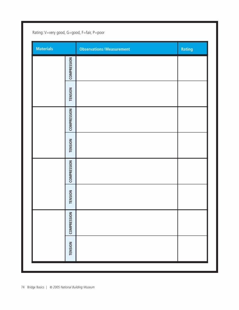
n Record your observations in the chart below. Use the following scale to indicate how resistant each materialis to the forces: V=very good, G=good, F=fair, P=poor
Materials Testing Worksheet
Materials Observations/Measurement Rating
Example: Sponge
Dented in/became compacted when compressed
G
Stretched then tore under tension / 2”
F
COM
PRES
SIO
NTE
NSI
ON
COM
PRES
SIO
NTE
NSI
ON
74 Bridge Basics | © 2005 National Building Museum
Rating: V=very good, G=good, F=fair, P=poor
Materials Observations/Measurement Rating
COM
PRES
SIO
NTE
NSI
ON
COM
PRES
SIO
NTE
NSI
ON
COM
PRES
SIO
NTE
NSI
ON
COM
PRES
SIO
NTE
NSI
ON

Student’s Name:
Group Being Evaluated:
Students: Evaluate your fellow classmates’ bridges, according to the following criteria.
For Student’s Use:
Scoring Range: “1” is the lowest score; “5” is the highest.
For Teacher’s Use:
Pasta Bridge Building Evaluation Sheet
80 Bridge Basics | © 2005 National Building Museum
Used only the materials provided (circle one) Yes No
Completed in 1 hour (circle one) Yes No
Cleared a span of 11 inches (circle one) Yes No
Total load supported (in grams and ounces)
Attractiveness (circle one) 1 2 3 4 5
Innovative design (circle one) 1 2 3 4 5
Effective group cooperation 1 2 3 4 5
Number of remaining points
This student worksheet accompanies the Unique American Bridges: A Research Project lesson.
Student’s Name:
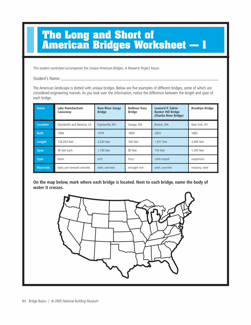
The American landscape is dotted with unique bridges. Below are five examples of different bridges, some of which areconsidered engineering marvels. As you look over the information, notice the difference between the length and span ofeach bridge.
On the map below, mark where each bridge is located. Next to each bridge, name the body ofwater it crosses.
The Long and Short of American Bridges Worksheet — 1
84 Bridge Basics | © 2005 National Building Museum
Name Lake PontchartrainCauseway
New River GorgeBridge
Bollman TrussBridge
Leonard P. Zakim Bunker Hill Bridge (Charles River Bridge)
Brooklyn Bridge
Location Mandeville and Metairie, LA Fayetteville, WV Savage, MD Boston, MA New York, NY
Built 1969 1978 1869 2003 1883
Length 126,054 feet 3,030 feet 160 feet 1,457 feet 3,460 feet
Span 56 feet each 1,700 feet 80 feet 754 feet 1,595 feet
Type beam arch truss cable-stayed suspension
Materials steel, pre-stressed concrete steel, concrete wrought iron steel, concrete masonry, steel
The Long and Short of American Bridges Worksheet — 2
Meters
0 250 500 750 1000 1250 1500
9
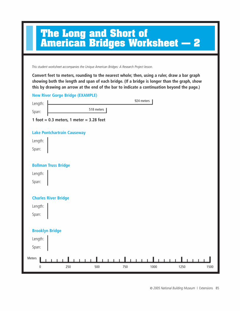
Convert feet to meters, rounding to the nearest whole; then, using a ruler, draw a bar graphshowing both the length and span of each bridge. (If a bridge is longer than the graph, showthis by drawing an arrow at the end of the bar to indicate a continuation beyond the page.)
New River Gorge Bridge (EXAMPLE)
Length:
Span:
1 foot = 0.3 meters, 1 meter = 3.28 feet
Lake Pontchartrain Causeway
Length:
Span:
Bollman Truss Bridge
Length:
Span:
Charles River Bridge
Length:
Span:
Brooklyn Bridge
Length:
Span:
924 meters
518 meters
This student worksheet accompanies the Unique American Bridges: A Research Project lesson.
© 2005 National Building Museum | Extensions 85

Analysis
1. What is the difference between the length and span of a bridge? Do you think that they are ever the same?
2. How does the bridge type relate to the distance it can span? How does the bridge type determine the totallength it can cross?
3. What do you notice about the relationship between the age of the bridges and the technology and materi-als used to construct them?
4. Suspension bridges typically span longer distances than other types of bridges. Why do you think the New River Gorge Bridge, an arch bridge, spans a longer distance than the Brooklyn Bridge, a suspension bridge?
(Hint: Some factors to consider include the age of the bridge, technology, materials, and geographic site.)
86 Bridge Basics | © 2005 National Building Museum

© 2005 National Building Museum | Extensions 87
This student worksheet accompanies the Unique American Bridges: A Research Project lesson.
Student’s Name:
Bridge:
Use the questions below to guide your research on your bridge.
1. Where is the bridge located?
2. What obstacle does the bridge cross?
3. When was the bridge built?
4. What materials were used to construct the bridge?
5. Which of the five basic bridge types best describes the bridge?
6. What types of traffic use the bridge?
7. What is the name of the engineer/architect (or engineering/architectural firm) who designed this bridge?
Answer the following questions.
1. Why do you think the engineer built this type of bridge for this site?
2. What were the special challenges that the architects and engineers faced while designing this bridge?
3. How did they overcome those challenges?
4. Did you find any interesting stories or fun facts about this bridge?
5. Do you like the way the bridge looks? If so, then why? If not, then why not?
Bridge Research Guide Worksheet

6. Are there decorative elements? If so, then what do they represent?
7. What is the name of the bridge? Why do you think that it was given this name?
8. How did the community where the bridge was built affect the bridge’s design and/or determination of its location?
9. Record the source information (e.g., Internet site, book, periodical) that you referenced to complete theresearch for this worksheet.
88 Bridge Basics | © 2005 National Building Museum
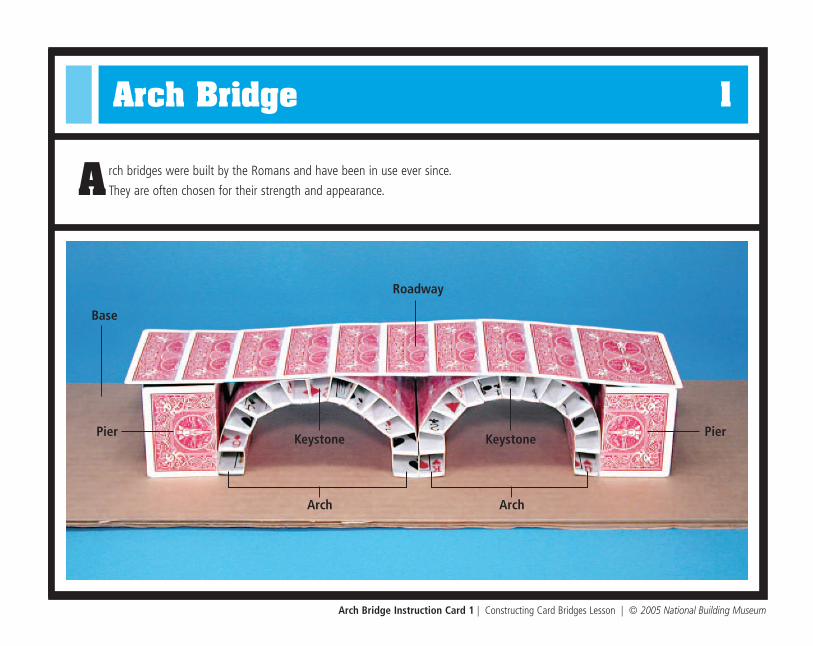
Arch Bridge 1
A rch bridges were built by the Romans and have been in use ever since.
They are often chosen for their strength and appearance.
Arch Bridge Instruction Card 1 | Constructing Card Bridges Lesson | © 2005 National Building Museum
Roadway
Pier
Base
KeystoneKeystone
Arch
Pier
Arch

Arch Bridge Instruction Card 1 | Constructing Card Bridges Lesson | © 2005 National Building Museum
Instructions for Building an Arch Bridge
1. Divide team in half.
2. One half takes Instruction Card 2 and the other takes Instruction Card 3.
3. After completing the individual bridge pieces, use Instruction Card 4 and work together as a whole team to construct the archbridge on the cardboard base.
4. When the bridge is constructed, cut the piece of copy paper into small rectangles. Use these smaller pieces and write the names of each bridge part on them. Refer to the labeled image of the bridge on the other side of this card for the names and locations of each part. Using tape, affix the labels to the appropriate locations on the finished arch bridge.
Needed Materials
n 1 deck of cards
n Scissors
n Cardboard base (6 x18”)
n Scotch tape
n Ruler
n Copy paper (1 piece) to create labels for bridge parts
n Object, such as a stapler, for testing bridge strength
Arch Bridge 2
Arch Bridge Instruction Card 2 | Constructing Card Bridges Lesson | © 2005 National Building Museum
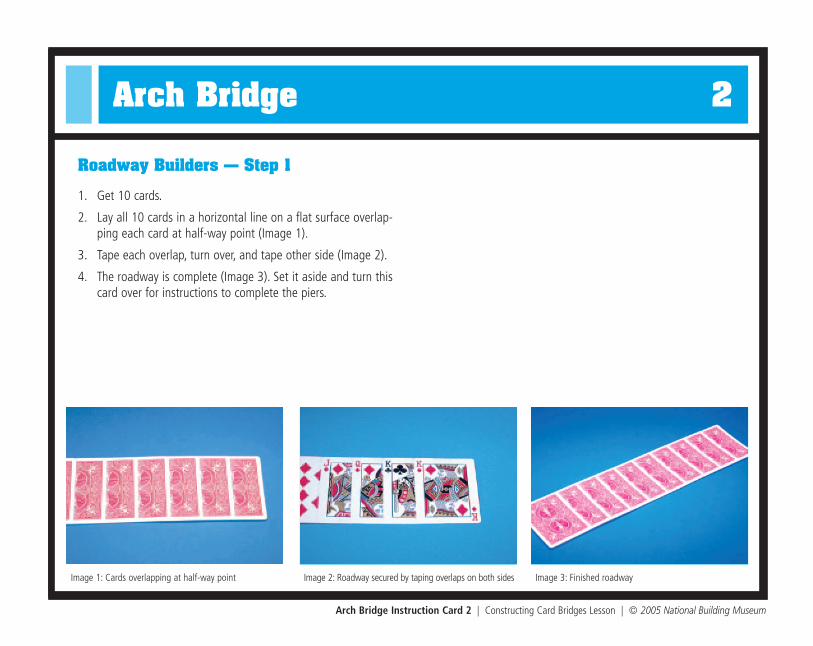
1. Get 10 cards.
2. Lay all 10 cards in a horizontal line on a flat surface overlap-ping each card at half-way point (Image 1).
3. Tape each overlap, turn over, and tape other side (Image 2).
4. The roadway is complete (Image 3). Set it aside and turn thiscard over for instructions to complete the piers.
Roadway Builders — Step 1
Image 1: Cards overlapping at half-way point Image 2: Roadway secured by taping overlaps on both sides Image 3: Finished roadway

Arch Bridge Instruction Card 2 | Constructing Card Bridges Lesson | © 2005 National Building Museum
Pier Builders — Step 2
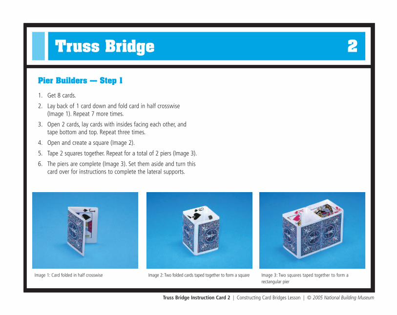
Image 1: Card folded in half crosswise Image 2: Two folded cards taped together to form a square Image 3: Two squares taped together to form a rectangular pier
1. Get 8 cards.
2. Lay back of 1 card down and fold card in half crosswise (Image 1). Repeat seven more times.
3. Open 2 cards, lay cards with insides facing each other, andtape bottom and top. Repeat three times.
4. Open and create a square (Image 2).
5. Tape 2 squares together (Image 3). Repeat for a total of 2 piers.
6. The piers are complete (Image 3). Set them aside and assistthe arch builders (Instruction Card 3).

Arch Bridge 3
Arch Bridge Instruction Card 3 | Constructing Card Bridges Lesson | © 2005 National Building Museum
1. Get 26 cards.
2. Lay back of 1 card down and fold card in half lengthwise.
3. Open card and fold long edges in toward the center crease(Image 1).
4. Repeat 25 more times for a total of 26 pieces.
5. Open, fold sides to create a rectangular shape, and tapeclosed (Image 2).
6. Repeat three more times for a total of 4 rectangular pieces.
7. With remaining 22 folded cards, open each card and trimapproximately 1/8” from ONE of the long sides (Image 3).
8. Fold each card into shape of a trapezoid and tape closed(Image 4).
9. The arch pieces are complete. There should be 4 rectangularpieces and 22 trapezoidal pieces.
TIP: As members of the team finish other parts of the bridge, theywill join the arch builders to help build the arch components.
Arch Builders — Step 1
Image 1: Card folded in four lengthwise Image 2: Finished rectangular piece Image 3: One side trimmed to create trapezoidal piece
Image 4: Completed rectangular and trapezoidal pieces

Arch Bridge 4
Arch Bridge Instruction Card 4 | Constructing Card Bridges Lesson | © 2005 National Building Museum
n 1 roadway
n 2 piers
n 22 trapezoidal pieces
n 4 rectangular pieces
n 1 cardboard base
n Scotch tape
n Ruler
n Stapler
1. Place two piers on cardboard baseabout 8” apart (Image 1).
2. Tape piers to base.
3. Place roadway on top of these piersand lightly tape it to them (Image 2).
4. Test strength of this basic bridge bysetting stapler (or other object) onroadway.
n What do you notice about the bridge?Where are its weak points?
How can you strengthen the bridge?
Arch Bridge Team Building Instructions — Step 1
Materials
Step 1 – Test a Basic Bridge
Image 2: Roadway placed across piers for test
Image 1: Rectangular piers placed and taped on cardboard base

Arch Bridge Instruction Card 4 | Constructing Card Bridges Lesson | © 2005 National Building Museum
Team Building Instructions — Steps 2 & 3
Step 2 – Build an Arch Bridge
1. Gently remove tape that connects roadway to piers and piers to base.
2. Lift roadway off structure and set to side.
3. Begin arch construction by connecting 1 trapezoidal piece to 1 rectangular piece alongtheir lengths (Image 1). (The rectangular piece is the base and should be on the bottom.)
4. Tape 4 more trapezoidal pieces to this stack until half arch is formed.
5. Repeat steps 3 and 4 three more times for a total of 4 half arches.
6. Complete each arch by standing 2 half arches up and placing another trapezoidal piecebetween them. This acts as the keystone (Image 2). Repeat this one more time for a totalof 2 complete arches (Image 3).
7. Situate 2 arches in a row on center of base and place a pier at either end. Secure entirestructure in place with tape.
8. To finish, place and tape roadway on top of arches and piers (Image 4).
Step 3 – Test the Bridge
1. Set stapler (or other object) on top of roadway.
n What do you notice about this bridge? Is it stronger than the first bridge? Why orwhy not?
Image 3: Arches secured to the piers by taping
Image 4: Completed arch bridge
Image 2: Trapezoidal pieces stacked until they form an arch
Image 1: Rectangular piece connected to a trapezoidal piece
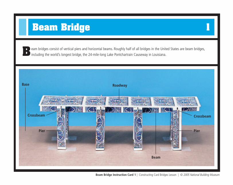
Beam Bridge 1
B eam bridges consist of vertical piers and horizontal beams. Roughly half of all bridges in the United States are beam bridges,
including the world’s longest bridge, the 24-mile-long Lake Pontchartrain Causeway in Louisiana.
Beam Bridge Instruction Card 1 | Constructing Card Bridges Lesson | © 2005 National Building Museum
Roadway
Pier
Crossbeam
Base
Beam
Pier
Crossbeam

Beam Bridge Instruction Card 1 | Constructing Card Bridges Lesson | © 2005 National Building Museum
Instructions for Building a Beam Bridge
1. Divide team in half.
2. One half takes Instruction Card 2 and the other takes Instruction Card 3.
3. After completing the individual bridge pieces, use Instruction Card 4 and work together as a whole team to construct the beambridge on the cardboard base.
4. When the bridge is constructed, cut the piece of copy paper into small rectangles. Use these smaller pieces and write the namesof each bridge part on them. Refer to the labeled image of the bridge on the other side of this card for the names and locations ofeach part. Using tape, affix the labels to the appropriate locations on the finished beam bridge.
Needed Materials
n 1 deck of cards
n Scissors
n Cardboard base (6 x18”)
n Scotch tape
n Ruler
n Copy paper (1 piece) to create labels for bridge parts
n Object, such as a stapler, for testing bridge strength

Beam Bridge 2
Beam Bridge Instruction Card 2 | Constructing Card Bridges Lesson | © 2005 National Building Museum
1. Get 6 cards.
2. Lay all 6 cards in a horizontal line on a flat surface overlap-ping each card at half-way point (Image 1).
3. Tape each overlap, turn over, and tape other side (Image 2).
4. The roadway is complete (Image 3). Set it aside and turn thiscard over for instructions to complete the beams.
Roadway Builders — Step 1
Image 1: Cards overlapping at half-way point Image 2: Roadway secured by taping overlaps on both sides Image 3: Finished roadway

Beam Bridge Instruction Card 2 | Constructing Card Bridges Lesson | © 2005 National Building Museum
Beam Builders — Step 2
Image 1: Card folded in four lengthwise Image 2: Small t-shaped beam piece Image 3: Finished beam
1. Get 8 cards.
2. Lay back of 1 card down and fold card in half lengthwise.
3. Open card, turn it over, and fold long edges in toward centercrease (Image 1).
4. Pinch two center rectangles together so card looks like the letter “T” (Image 2).
5. Repeat seven more times for a total of 8 beam pieces.
6. Use the 8 small beam pieces to create 2 long beams (Image 3):
n Overlap 4 beam pieces and adjust them to same length as roadway.
n Tape 4 beam pieces together to become 1 long beam.
n Repeat two steps above to create another long beam.
n When finished, there will be 2 long beams of equal length.

Beam Bridge 3
Beam Bridge Instruction Card 3 | Constructing Card Bridges Lesson | © 2005 National Building Museum
1. Get 4 cards.
2. Lay back of 1 card down and fold card in half lengthwise(Image 1).
3. Open card and fold long edges in toward center crease (Image 2).
4. Fold entire card in half again to create a long rectangle (Image 3).
5. Repeat three more times for a total of 4 crossbeams.
6. The crossbeams are complete. Set them aside and turn thiscard over for instructions to construct the piers.
Crossbeam Builders — Step 1
Image 1: Card folded in half lengthwise Image 2: Card folded in four lengthwise Image 3: Finished crossbeam

Beam Bridge Instruction Card 3 | Constructing Card Bridges Lesson | © 2005 National Building Museum
Pier Builders — Step 2
Image 1: Card folded in half lengthwise Image 2: Card folded in four lengthwise Image 3: Completed rectangular pier with slits
1. Get 8 cards.
2. Lay back of 1 card down and fold card in half lengthwise(Image 1).
3. Open card and fold long edges in toward center crease(Image 2).
4. Open card and form into a rectangular shape (Image 3).
5. Tape long edges of card together.
6. Repeat seven more times for a total of 8 piers.
7. Cut 2 v-shaped slits on opposite sides of the top of each pier (Image 3).

Beam Bridge 4
Beam Bridge Instruction Card 4 | Constructing Card Bridges Lesson | © 2005 National Building Museum
n 1 roadway
n 2 long beams
n 4 crossbeams
n 8 piers
n 1 cardboard base
n Scotch tape
n Scissors
n Ruler
n Stapler
1. Turn roadway upside-down and lightlytape 4 piers to underside of roadway(Image 1).
2. Turn roadway and piers right-side-upand stand on cardboard base (Image 2).
3. Tape piers to base.
4. Test strength of this basic bridge by setting stapler (or other object) on roadway.
n What do you notice about the bridge?Where are its weak points?
How can you strengthen the bridge?
Beam Bridge Team Building Instructions — Step 1
Materials
Step 1 – Test a Basic Bridge
Image 2: Bridge secured to base with tape for test
Image 1: Taped piers on underside of roadway

Beam Bridge Instruction Card 4 | Constructing Card Bridges Lesson | © 2005 National Building Museum
Team Building Instructions — Steps 2 & 3
Step 2 – Build a Beam Bridge
1. Gently remove tape that connects roadway to piers.
2. Lift roadway off structure and lay it upside-down.
3. Tape 2 long beams to underside of roadway so they parallel each other (Image 1).
4. Once in place, cut 4 v-shaped slits on each beam at the 1 1/2”, 4 1/2”, 7 1/2”, and 101/2” points. Make sure slits on both beams line up with each other.
5. Slide 4 crossbeams into slits on beams (Image 2).
6. Turn over and place the roadway with its attached beams and crossbeams onto piersalready taped to base. If piers need to be adjusted, remove taped piers and re-securethem in a better location (Image 3).
7. Test the bridge — set stapler (or other object) on top of roadway.
n What do you notice about this bridge? Is it stronger than the first bridge? Why or whynot? Where are the weak points? How could the bridge be strengthened?
Step 3 – Complete the Beam Bridge and Test
1. Slide 4 remaining piers onto outside edges of two interior crossbeams (Image 4).
2. Test bridge by placing a stapler on top of roadway.
n Is the bridge stronger? Why or why not?
Image 3: Bridge with four beams and four piers
Image 4: Completed bridge with beams, crossbeams, andeight piers
Image 2: Four crossbeams slid into slits on beams
Image 1: Two long beams taped to underside of roadway

Cable-Stayed Bridge 1
C able-stayed bridges have one or more pylons, each of which anchors a set of cables attached to the roadway. These bridges
were created as an economical way to span long distances.
Cable-Stayed Bridge Instruction Card 1 | Constructing Card Bridges Lesson | © 2005 National Building Museum
Roadway
Cable
Pier
Pylon
Base
Beam

Cable-Stayed Bridge Instruction Card 1 | Constructing Card Bridges Lesson | © 2005 National Building Museum
Instructions for Building a Cable-Stayed Bridge
1. Divide team in half.
2. One half takes Instruction Card 2 and the other takes Instruction Card 3.
3. After completing the individual bridge pieces, use Instruction Card 4 and work together as a whole team to construct thecable-stayed bridge on the cardboard base.
4. When the bridge is constructed, cut the piece of copy paper into small rectangles. Use these smaller pieces and write the namesof each bridge part on them. Refer to the labeled image of the bridge on the other side of this card for the names and locationsof each part. Using tape, affix the labels to the appropriate locations on the finished cable-stayed bridge.
Needed Materials
n 1 deck of cards
n Scissors
n Single-hole punch
n 26’ of string
n Cardboard base (6 x18”)
n Scotch tape
n Ruler
n Copy paper (1 piece) to create labels for bridge parts
n Object, such as a stapler, for testing bridge strength

Cable-Stayed Bridge 2
Cable-Stayed Bridge Instruction Card 2 | Constructing Card Bridges Lesson | © 2005 National Building Museum
1. Get 8 cards.
2. Lay all 8 cards in a horizontal line on a flat surface overlapping each card at half-way point (Image 1).
3. Tape each overlap, turn over, and tape other side.
4. Measure along the roadway’s long side and mark with a pencil at 3 1⁄2” and 12”.
5. Cut out a 3⁄4 x 3⁄4” notch at each mark (Image 2).
6. Repeat steps 4 and 5 on other long side of roadway.
7. Punch five, evenly-spaced holes on both sides of notch nearedge of roadway (Image 2).
8. Repeat step 7 with 3 remaining notches for a total of 20holes on each side of roadway (Image 3).
9. The roadway is complete (Image 3). Set it aside and turn thiscard over for instructions to construct the beams and cables.
Roadway Builders — Step 1
Image 1: Roadway consisting of eight cards overlappingat half-way points
Image 2: Roadway with four notches and five holespunched to either side of notch
Image 3: Finished roadway with four notches and 40 holes

Cable-Stayed Bridge Instruction Card 2 | Constructing Card Bridges Lesson | © 2005 National Building Museum
Beam Builders — Step 2
Image 1: Card folded in four lengthwise Image 2: Card folded into rectangular shape Image 3: Four pieces of each length string required tocomplete cables
1. Get 2 cards.
2. Lay back of 1 card down and fold card in half lengthwise.
3. Open card and fold long edges in toward center crease(Image 1).
4. Fold entire card in half again to create a long rectangle(Image 2).
5. Secure with tape.
6. Repeat steps 2-5 to create another beam.
Cable Cutters — Step 3
1. Get 26’ of string.
2. Cut 4 pieces of each length: 22”, 18”, 14”, 13”, 10”(Image 3).
Cable-Stayed Bridge 3
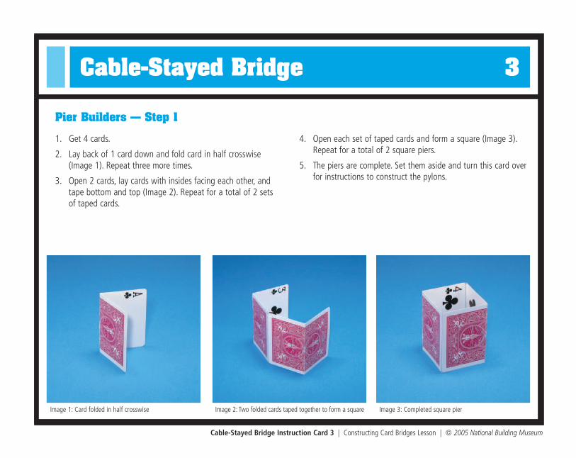
Cable-Stayed Bridge Instruction Card 3 | Constructing Card Bridges Lesson | © 2005 National Building Museum
1. Get 4 cards.
2. Lay back of 1 card down and fold card in half crosswise(Image 1). Repeat three more times.
3. Open 2 cards, lay cards with insides facing each other, andtape bottom and top (Image 2). Repeat for a total of 2 sets of taped cards.
4. Open each set of taped cards and form a square (Image 3).Repeat for a total of 2 square piers.
5. The piers are complete. Set them aside and turn this card overfor instructions to construct the pylons.
Pier Builders — Step 1
Image 1: Card folded in half crosswise Image 2: Two folded cards taped together to form a square Image 3: Completed square pier

Cable-Stayed Bridge Instruction Card 3 | Constructing Card Bridges Lesson | © 2005 National Building Museum
Pylon Builders — Step 2
Image 1: Card folded in four lenthwise
Image 2: Folded card with two holespunched close to fold
Image 3: Completed triangular shape Image 4: Completed tower using four triangular shapes
1. Get 16 cards.
2. Lay back of 1 card down and fold card in half lengthwise.
3. Open card and fold long edges in toward center crease(Image 1).
4. Open card, fold in half lengthwise, and punch 2 holes 1”apart close to fold (Image 2).
5. Open card, overlap long edges to form a triangular shape,and tape closed (Image 3).
6. Repeat steps 2-5, 15 times for a total of 16 hole-punchedtriangular shapes.
7. Make a pylon by inserting 1⁄2” of one triangular piece intoanother. Continue stacking pieces to complete a pylon of 4 stacked pieces (Image 4).
8. Repeat step 7 three more times for a total of 4 pylons.
9. Create flaps at bottom of each pylon by cutting 1⁄2” slits in all 3 corners. Fold flaps back to enable pylons to stand on a flat surface (Image 3).
TIP: Be sure to take turns with the hole punches to avoidsore hands.

Cable-Stayed Bridge 4
Cable-Stayed Bridge Instruction Card 4 | Constructing Card Bridges Lesson | © 2005 National Building Museum
n 1 roadway
n 2 piers
n 4 pylons
n 2 beams
n 1 cardboard base
n 20 measured cables
n Scotch tape
n Scissors
n Ruler
n Stapler
1. Place 2 square piers on cardboardbase about 8” apart (Image 1).
2. Place roadway on top piers and lightly tape it to them (Image 2).
3. Test strength of this basic bridge by setting stapler (or other object) on roadway.
n What do you notice about the bridge?Where are its weak points?
How can you strengthen the bridge?
Cable-Stayed Bridge Team Building Instructions —Step 1
Materials
Step 1 – Test a Basic Bridge
Image 2: Roadway placed across pier for test
Image 1: Square piers placed on cardboard base 8” apart

Cable-Stayed Bridge Instruction Card 4 | Constructing Card Bridges Lesson | © 2005 National Building Museum
Team Building Instructions — Steps 2 & 3
Image 3: Piers moved to outer ends of bridge andsecured with tape after cables are tied
Step 2 – Build a Cable-Stayed Bridge
1. Gently remove tape that connects roadway to piers.
2. Lift roadway off structure and set to side.
3. Place 2 pylons 8” apart (sides with holes should face out) and secure flaps at bottom to card-board using tape (Image 1).
4. Lay roadway next to taped pylons lining up with notches and place other 2 pylons in opennotches of roadway; secure flaps at bottom to cardboard base using tape.
5. Create 4 sets of cables by grouping one of each string length ( 22”, 18”, 14”, 13”, 10”).Each cable set will include 5 different string lengths.
6. Using 1 cable set and starting with shortest piece, thread each cable through a set of holes in1 pylon, and tie each cable end to holes in roadway using a double knot. Each cable forms atriangle (Image 2). Make sure that roadway is level while tying.
7. Repeat step 6 with 3 remaining towers.
8. For added stability, cut a 1⁄2” v-shaped slit in the top of each tower, on side facing the roadway.
9. Place a beam in between each set of towers and secure with tape.
10. Place each pier 2” from pylons and tape to cardboard base (Image 3).
Step 3 – Test the Bridge
1. Set stapler (or other object) on top of roadway.
n What do you notice about this bridge? Is it stronger than the first bridge? Why or why not?
Image 1: Two towers placed 8” apart and securedwith tape
Image 2: Bridge cables connected with roadway level
Suspension Bridge 1
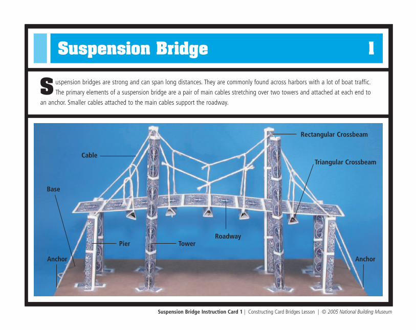
S uspension bridges are strong and can span long distances. They are commonly found across harbors with a lot of boat traffic.
The primary elements of a suspension bridge are a pair of main cables stretching over two towers and attached at each end to
an anchor. Smaller cables attached to the main cables support the roadway.
Suspension Bridge Instruction Card 1 | Constructing Card Bridges Lesson | © 2005 National Building Museum
RoadwayPier Tower
Triangular Crossbeam
Anchor
Rectangular Crossbeam
Base
Cable
Anchor

Suspension Bridge Instruction Card 1 | Constructing Card Bridges Lesson | © 2005 National Building Museum
Instructions for Building a Suspension Bridge
1. Divide team in half.
2. One half takes Instruction Card 2 and the other takes Instruction Card 3.
3. After completing the individual bridge pieces, use Instruction Card 4 and work together as a whole team to construct the suspension bridge on the cardboard base.
4. When the bridge is constructed, cut the piece of copy paper into small rectangles. Use these smaller pieces and write the names of each bridge part on them. Refer to the labeled image of the bridge on the other side of this card for the names and locations of each part. Using tape, affix the labels to the appropriate locations on the finished suspension bridge.
Needed Materials
n 1 deck of cards
n Scissors
n 16’ string
n Cardboard base (6 x18”)
n Scotch tape
n Ruler
n Copy paper (1 piece) to create labels for bridge parts
n Object, such as a stapler, for testing bridge strength

Suspension Bridge 2
Suspension Bridge Instruction Card 2 | Constructing Card Bridges Lesson | © 2005 National Building Museum
1. Get 6 cards.
2. Lay all 6 cards in a horizontal line on a flat surface overlap-ping each card at half-way point (Image 1).
3. Tape each overlap, turn over, and tape other side (Image 2).
4. The roadway is complete (Image 3). Set it aside and turn thiscard over for instructions to complete the towers.
Roadway Builders — Step 1
Image 1: Cards overlapping at half-way point Image 2: Roadway secured by taping overlaps on both sides Image 3: Finished roadway

Suspension Bridge Instruction Card 2 | Constructing Card Bridges Lesson | © 2005 National Building Museum
Tower Builders — Step 2
Image 1: Card folded in four lengthwise Image 2: Completed triangular shape Image 3: Completed tower
1. Get 16 cards.
2. Lay back of 1 card down and fold card in half lengthwise.
3. Open card and fold long edges in toward center crease(Image 1).
4. Open card, overlap long edges to form a triangular shape,and tape closed (Image 2).
5. Repeat steps 2–4, 15 times for a total of 16 triangular shapes.
6. Make a tower by inserting 1/2” of 1 triangular piece intoanother. Continue stacking pieces to complete a tower of 4stacked pieces (Image 3).
7. Repeat step 6 three more times for a total of 4 towers ofequal length.
8. Create flaps at the bottom of each tower by cutting 1⁄2” slitsin all 3 corners. Fold flaps back to enable towers to stand ona flat surface (Image 3).

Suspension Bridge 3
Suspension Bridge Instruction Card 3 | Constructing Card Bridges Lesson | © 2005 National Building Museum
1. Get 4 cards.
2. Lay back of 1 card down and fold card in half lengthwise.
3. Open card and fold long edges in toward center crease (Image 1).
4. Fold entire card in half again to create a long rectangle (Image 2).
5. Secure with tape.
6. Repeat steps 2–5 three times for a total of 4 rectangularcrossbeams.
Crossbeam Builders — Step 1 (Rectangular Crossbeams)
Image 1: Card folded in four lengthwise Image 2: Card folded into the shape of rectangle Image 3: Triangular shape
Step 2 (Triangular Crossbeams)
1. Get 5 cards.
2. Like rectangular crossbeam, fold 1 card into four sections lengthwise.
3. Shape into a triangle and secure with tape (Image 3).
4. Repeat steps 2 and 3 four times for a total of 5 triangularcrossbeams.
5. The crossbeams are complete (Image 3). Set them aside andturn this card over for instructions to complete the piers.
Suspension Bridge Instruction Card 3 | Constructing Card Bridges Lesson | © 2005 National Building Museum
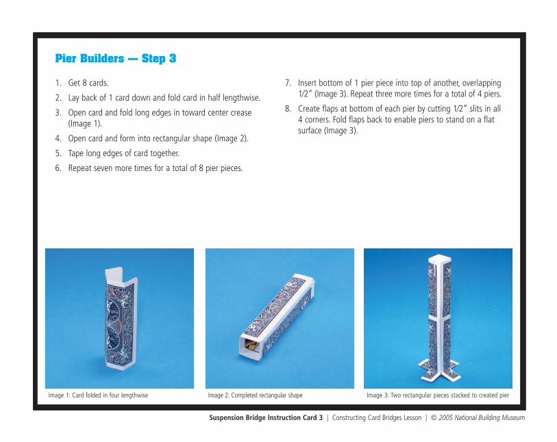
Pier Builders — Step 3
Image 1: Card folded in four lengthwise Image 2: Completed rectangular shape Image 3: Two rectangular pieces stacked to created pier
1. Get 8 cards.
2. Lay back of 1 card down and fold card in half lengthwise.
3. Open card and fold long edges in toward center crease(Image 1).
4. Open card and form into rectangular shape (Image 2).
5. Tape long edges of card together.
6. Repeat seven more times for a total of 8 pier pieces.
7. Insert bottom of 1 pier piece into top of another, overlapping1⁄2” (Image 3). Repeat three more times for a total of 4 piers.
8. Create flaps at bottom of each pier by cutting 1⁄2” slits in all4 corners. Fold flaps back to enable piers to stand on a flatsurface (Image 3).
Suspension Bridge 4
Suspension Bridge Instruction Card 4 | Constructing Card Bridges Lesson | © 2005 National Building Museum
n 1 roadway
n 4 piers
n 4 towers
n 4 rectangular crossbeams
n 5 triangular crossbeams
n 1 cardboard base
n 2 48” long cables
n 5 18” long cables
n Scotch tape
n Scissors
n Ruler
n Stapler
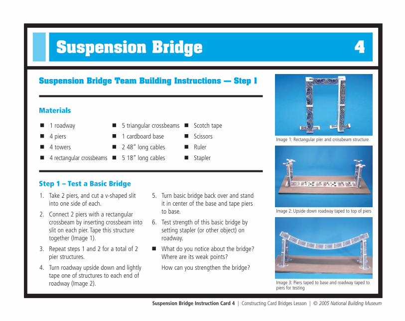
1. Take 2 piers, and cut a v-shaped slitinto one side of each.
2. Connect 2 piers with a rectangularcrossbeam by inserting crossbeam intoslit on each pier. Tape this structuretogether (Image 1).
3. Repeat steps 1 and 2 for a total of 2pier structures.
4. Turn roadway upside down and lightlytape one of structures to each end ofroadway (Image 2).
5. Turn basic bridge back over and standit in center of the base and tape piersto base.
6. Test strength of this basic bridge bysetting stapler (or other object) onroadway.
n What do you notice about the bridge?Where are its weak points?
How can you strengthen the bridge?
Suspension Bridge Team Building Instructions — Step 1
Materials
Step 1 – Test a Basic Bridge
Image 3: Piers taped to base and roadway taped topiers for testing
Image 1: Rectangular pier and crossbeam structure
Image 2: Upside down roadway taped to top of piers
Suspension Bridge Instruction Card 4 | Constructing Card Bridges Lesson | © 2005 National Building Museum
Team Building Instructions — Steps 2 & 3
Step 2 – Build a Suspension Bridge
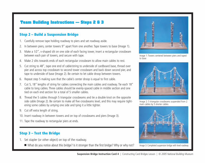
1. Carefully remove tape holding roadway to piers and set roadway aside.
2. In between piers, center towers 9” apart from one another. Tape towers to base (Image 1).
3. Make a 1⁄2”, v-shaped slit on one side of each facing tower, insert a rectangular crossbeambetween each pair of towers, and secure with tape.
4. Make 2 slits towards ends of each rectangular crossbeam to allow main cables to rest.
5. Cut string to 48”, tape one end of cable/string to underside of cardboard base, thread overpier and across top crossbeam to second tower crossbeam and back down second pier, andtape to underside of base (Image 2). Be certain to let cable droop between towers.
6. Repeat step 5 making sure that the cable’s center droop is equal to first cable.
7. Cut 5, 18” lengths of string for cables connecting the main cables and roadway. Tie each 18”cable to long cables. Three cables should be evenly-spaced cable in middle section and onetied on each end section for a total of 5 smaller cables.
8. Thread the 5 cables through 5 triangular crossbeams and tie a double knot on the oppositeside cable (Image 2). Be certain to make all five crossbeams level, and this may require tight-ening some cables by untying one side and tying it a little tighter.
9. Cut off extra length of string.
10. Insert roadway in between towers and on top of crossbeams and piers (Image 3).
11. Tape the roadway to rectangular piers at ends.
Step 3 – Test the Bridge
1. Set stapler (or other object) on top of the roadway.
n What do you notice about this bridge? Is it stronger than the first bridge? Why or why not? Image 3: Completed suspension bridge with level roadway
Image 1: Towers centered between piers and tapedto base
Image 2: 5 triangular crossbeams suspended from 2main cables by 5 shorter cables

Truss Bridge 1
A truss is a rigid support structure made of interlocking triangles. Since the triangle is the strongest shape, truss bridges are quite
strong. Many railroad bridges utilize a truss system because of the heavy load that they can support.
Truss Bridge Instruction Card 1 | Constructing Card Bridges Lesson | © 2005 National Building Museum
RoadwayPier
Base
Lateral Support
Pier
Truss

Truss Bridge Instruction Card 1 | Constructing Card Bridges Lesson | © 2005 National Building Museum
Instructions for Building a Truss Bridge
1. Divide team in half.
2. One half takes Instruction Card 2 and the other takes Instruction Card 3.
3. After completing the individual bridge pieces, use Instruction Card 4 and work together as a whole team to construct the trussbridge on the cardboard base.
4. When the bridge is constructed, cut the piece of copy paper into small rectangles. Use these smaller pieces and write the namesof each bridge part on them. Refer to the labeled image of the bridge on the other side of this card for the names and locationsof each part. Using tape, affix the labels to the appropriate locations on the finished truss bridge.
Needed Materials
n 1 deck of cards
n 18 brass fasteners
n 3 single-hole punches
n Scissors
n Cardboard base (6 x18”)
n Scotch tape
n Ruler
n Copy paper (1 piece) to create labels for bridge parts
n Object, such as a stapler, for testing bridge strength
Truss Bridge 2
Truss Bridge Instruction Card 2 | Constructing Card Bridges Lesson | © 2005 National Building Museum
1. Get 8 cards.
2. Lay back of 1 card down and fold card in half crosswise(Image 1). Repeat 7 more times.
3. Open 2 cards, lay cards with insides facing each other, andtape bottom and top. Repeat three times.
4. Open and create a square (Image 2).
5. Tape 2 squares together. Repeat for a total of 2 piers (Image 3).
6. The piers are complete (Image 3). Set them aside and turn thiscard over for instructions to complete the lateral supports.
Pier Builders — Step 1
Image 1: Card folded in half crosswise Image 2: Two folded cards taped together to form a square Image 3: Two squares taped together to form a rectangular pier

Truss Bridge Instruction Card 2 | Constructing Card Bridges Lesson | © 2005 National Building Museum
Lateral Support Builders — Step 2
Image 1: Card folded in four lengthwise Image 2: Card folded into rectangular shape Image 3: Finished card with hole-punched ends folded1/2” from both edges
1. Get 9 cards.
2. Lay back of 1 card down and fold card in half lengthwise.
3. Open card and fold long edges in toward center crease(Image 1).
4. Fold entire card in half again to create a long rectangle(Image 2).
5. Make a fold 1/2” from each edge of the rectangle, leaving a90° angle (Image 3).
6. Punch a hole in center of folded portion on both sides(Image 3).
7. Repeat eight more times for a total of 9 lateral supports.
8. When lateral supports are complete, set these aside andhelp the truss beam builders (Instruction Card 3).

Truss Bridge 3
Truss Bridge Instruction Card 3 | Constructing Card Bridges Lesson | © 2005 National Building Museum
1. Get 6 cards.
2. Lay all 6 cards in a horizontal line on a flat surface overlapping each card at half-way point (Image 1).
3. Tape each overlap, turn over, and tape other side (Image 2).
4. The roadway is complete (Image 3). Set it aside and turn this card over for instructions to complete the truss beams.
Roadway Builders — Step 1
Image 1: Cards overlapping at half-way point Image 2: Roadway secured by taping overlaps on both sides Image 3: Finished roadway
Truss Bridge Instruction Card 3 | Constructing Card Bridges Lesson | © 2005 National Building Museum
Truss Beam Builders — Step 2
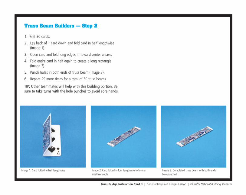
Image 1: Card folded in half lengthwise Image 2: Card folded in four lengthwise to form a small rectangle
Image 3: Completed truss beam with both ends hole-punched
1. Get 30 cards.
2. Lay back of 1 card down and fold card in half lengthwise(Image 1).
3. Open card and fold long edges in toward center crease.
4. Fold entire card in half again to create a long rectangle(Image 2).
5. Punch holes in both ends of truss beam (Image 3).
6. Repeat 29 more times for a total of 30 truss beams.
TIP: Other teammates will help with this building portion. Besure to take turns with the hole punches to avoid sore hands.

Truss Bridge 4
Truss Bridge Instruction Card 4 | Constructing Card Bridges Lesson | © 2005 National Building Museum
n 1 roadway
n 2 piers
n 30 truss beams
n 9 lateral supports
n 1 cardboard base
n Scotch tape
n 18 brass fasteners
n Ruler
n Stapler
1. Place 2 square piers on cardboardbase about 5” apart (Image 1).
2. Tape piers to base.
3. Place the roadway on top of piers andlightly tape it to them (Image 2).
4. Test the strength of this basic bridgeby setting stapler (or other object) on roadway.
n What do you notice about the bridge?Where are its weak points?
How can you strengthen the bridge?
Truss Bridge Team Building Instructions — Step 1
Materials
Step 1 – Test a Basic Bridge
Image 2: Roadway placed across piers for test
Image 1: Rectangular piers placed on cardboard base
Truss Bridge Instruction Card 4 | Constructing Card Bridges Lesson | © 2005 National Building Museum
Team Building Instructions — Steps 2 & 3
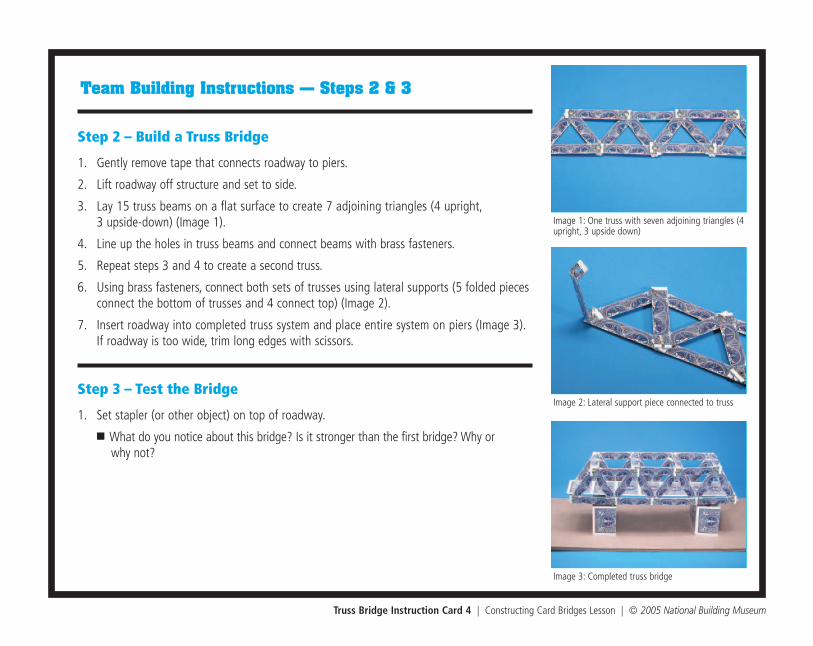
Step 2 – Build a Truss Bridge
1. Gently remove tape that connects roadway to piers.
2. Lift roadway off structure and set to side.
3. Lay 15 truss beams on a flat surface to create 7 adjoining triangles (4 upright,3 upside-down) (Image 1).
4. Line up the holes in truss beams and connect beams with brass fasteners.
5. Repeat steps 3 and 4 to create a second truss.
6. Using brass fasteners, connect both sets of trusses using lateral supports (5 folded piecesconnect the bottom of trusses and 4 connect top) (Image 2).
7. Insert roadway into completed truss system and place entire system on piers (Image 3).If roadway is too wide, trim long edges with scissors.
Step 3 – Test the Bridge
1. Set stapler (or other object) on top of roadway.
n What do you notice about this bridge? Is it stronger than the first bridge? Why or why not?
Image 3: Completed truss bridge
Image 1: One truss with seven adjoining triangles (4upright, 3 upside down)
Image 2: Lateral support piece connected to truss

Arch BridgesArch Bridges
Bridge Basics Program Kit | © 2005 National Building Museum
Natchez Trace Parkway Arches
Engineer Conde McCullough
Location: Gold Beach, OR
Completed: 1932
Spans: 230 ft.
Engineer HNTB Corporation
Location: Nashville, TN
Completed: 2004
Span: 545 ft.
Engineer unknown
Location: Savage, MD
Completed: 1834
Spans: 40 ft.
Gateway Boulevard Bridge
Rogue River Bridge Antietam Aqueduct
Courtesy of FIGG Courtesy of HNTB/Mark McCabe, 2005
Courtesy of Oregon Department of Transportation Courtesy of Lawrence Biemiller
Engineer FIGG
Location: near Nashville, TN
Completed: 1994
Spans: 580 ft.

Beam BridgesBeam Bridges
Bridge Basics Program Kit | © 2005 National Building Museum
Engineer FIGG
Location: Glenwood Canyon, CO
Completed: 1993
Spans: 300 ft.
Hanging Lake Viaduct
Engineer FIGG
Location: San Antonio, TX
Completed: 1989
Spans: 100 ft.
Engineer unknown
Location: Yellowstone, WY
Completed: 1932
Spans: ranging 16–34 ft.
Engineer unknown
Location: Hyde County, NC
Completed: 1981
Spans: ranging 70–120 ft.
Seven Mile River Bridge
San Antonio "“Y” Bridges Walter B. Jones Bridge
Courtesy of FIGG Courtesy of National Park Service
Courtesy of FIGG Courtesy of North Carolina Department of Traffic

Cable-Stayed BridgesCable-Stayed Bridges
Bridge Basics Program Kit | © 2005 National Building Museum
Location: St. Georges, DE
Completed: 1995
Span: 750 ft.
Chesapeake and Delaware Canal Bridge Engineer FIGG
Engineer FIGG
Location: Tampa/St. Petersburg, FL
Completed: 1987
Span: 1200 ft.
Engineer DRC Consultants
Location: Baytown/Laporte, TX
Completed: 1995
Span: 1250 ft.
Engineer FIGG
Location: near Richmond, VA
Completed: 1990
Span: 630 ft.
Fred Hartman Bridge
Sunshine Skyway Bridge Varina-Enon Bridge
Courtesy of FIGG Courtesy of Stan Williams/TxDOT
Courtesy of FIGG Courtesy of Virginia Department of Transportation

Suspension BridgesSuspension Bridges
Bridge Basics Program Kit | © 2005 National Building Museum
Engineer John A. Roebling
Location: Brooklyn, NY
Completed: 1883
Span: 1595 ft.
Brooklyn Bridge
Engineer Joseph B. Strauss
Location: San Francisco, CA
Completed: 1937
Span: 4200 ft.
Engineer Othmar Ammann
Location: New York, NY
Completed: 1964
Span: 4260 ft.
Engineer George F. Cole
Location: Canon City, CO
Completed: 1929
Span: 880 ft.
Verrazano-Narrows Bridge
Golden Gate Bridge Royal Gorge Bridge
©MTA Bridges and Tunnels Special Archive
Courtesy of Harris PhotographyUsed with permission from The Golden Gate Bridge, Highway and Transportation District, San Francisco, CA,
www.goldengatebridge.org
Library of Congress, Prints and Photographs Division, Historic American Engineering Record, HAER NY, 31-NEYO, 90-79
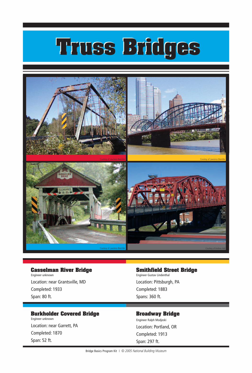
Truss BridgesTruss Bridges
Bridge Basics Program Kit | © 2005 National Building Museum
Engineer unknown
Location: near Grantsville, MD
Completed: 1933
Span: 80 ft.
Casselman River Bridge
Engineer unknown
Location: near Garrett, PA
Completed: 1870
Span: 52 ft.
Engineer Gustav Lindenthal
Location: Pittsburgh, PA
Completed: 1883
Spans: 360 ft.
Engineer Ralph Modjeski
Location: Portland, OR
Completed: 1913
Span: 297 ft.
Smithfield Street Bridge
Burkholder Covered Bridge Broadway Bridge
Courtesy of Lawrence Biemiller Courtesy of Lawrence Biemiller
Courtesy of Lawrence Biemiller Courtesy of Andrew Hall