Embed Size (px)
Citation preview

Gutierrez-Serret, R., Grassa, J.M. and Grau, J.I. 1
Breakwater development in Spain. The last ten years Gutierrez-Serret Ramón, Centro de Estudios de Puertos y Costas - Centro de Estudios y Experimentación de Obras Públicas (CEDEX), Ministry of Public Works Madrid, Spain. Grassa, José M., Centro de Estudios de Puertos y Costas - Centro de Estudios y Experimentación de Obras Públicas (CEDEX), Ministry of Public Works, Madrid, Spain. Grau, Juan I., Organismo Público Puertos del Estado, Ministry of Public Works, Madrid, Spain. Introduction The aim of this paper is to provide a general and mainly descriptive overview of the major port breakwater development that have taken place in Spain in the last 10 years or that are still being carried out, especially in the design and construction fields. It must be mentioned that, along the Spanish economic growth and with the impact of globalisation, handling of goods in Spanish Ports increased by 57 % in the period 1997-2007, against an average percentage for the 15 countries of 26 %, according to EUROSTAT, and this explain in part the need for extended the Spanish port infrastructures. The most significant activities undertaken in the State Port System -28 Port Authorities that manage 44 ports- under the coordination of the Public Body State Ports are presented within this context. It is clear that it is not possible to include details from all the activities carried out in the State Port System and the Autonomous Regions -10 Regions with coastline, which manage a host of smaller ports-, but those actions that do not fall within the scope of this article are available to whoever that might be interested in obtaining further information. An attempt has been made to include certain examples (some of which are the subject of specific papers at the Conference) which best illustrate the major problems that Spanish port engineering has been faced with and the innovative solutions that it has found to overcome them -great depths, strong waves or singular geotechnical problems-, which are determined by the need to build new ports with no or few natural protection, not only because of the general lack of zones that afford natural shelter along the Spanish coast, but also for environmental reasons, which make it very difficult to construct these works in bays, estuaries or river mouths, which is where the major ports of the world used to carry out their developments. This circumstance, the lack of natural sheltered waters, is not new to Spain. Although ports were traditionally located in bays and estuaries, along the shoreline or in rivers, the aforementioned nature of the Spanish coast, led to a need for breakwaters along the history. In this respect, the following can be mentioned[1]: the Roman breakwater Bares Port in the NW of the Iberian Peninsula; the breakwaters of Santander (1575), Gijón (1635), and in the 18th Century those of Málaga, Valencia and Barcelona Ports (Figure 1). Breakwater construction sharply increased in the 19th Century, a trend which continued into the 20th Century.

Gutierrez-Serret, R., Grassa, J.M. and Grau, J.I. 2
Figure 1. Breakwaters of the Ports of Santander (1575), Gijón (1635) and Málaga (1784) In the last few decades of the 20th Century, the following breakwaters were among the most outstanding: Bilbao (Punta Lucero, 1985), Gijón (Príncipe de Asturias, 1976), Las Palmas (Reina Sofía, 1972 and subsequent ones) and Tenerife (Los Llanos, 1980 and previous ones). A concise description of these breakwaters is given in the following section, by way of providing a background to those constructed in the last ten years. On the contrary, one question that has been a new and major challenge to Spanish port engineering over the last ten years, and will continue to be in the future, is the sheer scale and singularity of the port enlargements that have taken place and the problems that these circumstances have caused and are still causing. In this sense, and within the scope of the State Port System, a special mention must be made of the following: the magnitude of the breakwaters that have been provided for the new outer ports of Gijón, Ferrol and Coruña, in the Atlantic Ocean, which are 3.8; 1 and 3.4 km long, have maximum heights of 48, 49 and 64 m and design significant waves height (Hs) of 9.5; 7.6 and 15 m, respectively, being of rubble mound and caissons typologies; the enlargement to the Algeciras port, with a 2 Km. low reflection vertical breakwater with drafts ranging from 30 to 40 m; the enlargements to the Escombreras Basin in the Cartagena port, with a 1 Km. long vertical breakwater down to a depth of 50 m, and the geotechnical problems caused by the mud lying at the foundation of the two breakwaters of the Barcelona port enlargement. Apart from those referred to above, other smaller breakwaters have been constructed that are also of great importance: Málaga, Motril, Alicante, Valencia, Sagunto, Castellón, Tarragona, Barcelona (North Mouth), Ibiza and Las Palmas (Reina Sofía and Esfinge). Over the past 10 years, about 32.2 km of large breakwaters have been constructed, 15.4 km of the rubble mound type and 16.8 km of vertical type. Table 1 provides a summary of the characteristics of all the breakwaters mentioned, and figure 2 and 3 their nomenclature and locations. Reference is also made to certain details of the physical tests conducted at the CEDEX for its design and construction, nevertheless many of the cited breakwaters have also been tested at others EU laboratories in Denmark, Netherlands, Portugal, Spain, UK and elsewhere.
Figure 2. Rubble mound and vertical breakwaters. Nomenclature.

Gutierrez-Serret, R., Grassa, J.M. and Grau, J.I. 3
RUBBLE MOUND BREAKWATERS CONSTRUCTED IN THE LAST 10 YEARS
Name L (m)
Dmax (m)
B (m)
C (m)
h (m)
W (t)
S (H/V)
HS design
(m)
t (m) State
Torres. Gijón. 1,450 -22 - 22 44 145 2:1 9.5 4.6 Being Constructed
Outer Port . Ferrol 1,100 - 33 -15 18 51 90 3.5:2 7.60 4.5 Completed Outer Port.
Coruña. 4,000 -42 -28 25 67 150 2:1 15.1 4.5 Being Constructed
Enlargement North Valencia. 1,123 -16 -9 12 28 35 3:2 6.3 1 Being
Constructed East. Barcelona. 2,165 -20 -10 12 32 50 3.5:2 7.3 0 Completed
South. 1 & 2. Barcelona 3,100 -23
-27 -14 11 33/38 40 1.75:1 7.3 Completed
North mouth. Barcelona 1,000 -25.2 -10 11 35.2 40 3:2 6.4 0 Completed
Alicante 1,200 -16 -8 7.5 23.5 20 3:2 4.4 0 Completed Esfinge.
Las Palmas 302 -39 -10 15 54 56 3:2 7,3 3.0 Completed
Total length: 15,440 m Length constructed: 8,867 m Length under construction: 6,573 m VERTICAL BREAKWATERS CONSTRUCTED IN THE LAST 10 YEARS
Name L (m) Dmax (m) B (m) C
(m) W (m) h (m)
HS design
(m)
t (m) State
North. Gijón 1,588 -30 -24.75 24 32.01 48.75 9.5 4.6 Being Constructed
Isla Verde. Algeciras 1,750 -43 32.5 7.5 21.4 40 4.8 1.3 Completed
Levante. Málaga 1,200 -20 -20 10 21.1 30 6.3 0.8 Completed Motril 550 -20 -12 7.5 21.1 91.5 6.3 Completed
Enlargement Escombreras.
Cartagena 1.955 -52 -28 8 24 32 8.1 0.6 Completed
Enlargement North. Valencia 2,271 -16 - 13 19.17 29 6.3 1 Being
Constructed Sagunto 1,204 -15 - 9 19.6 24 6.4 0 Completed
East. Castellón 440 -12 -13 12 19.6 25 7.3 0.5 Completed East extension.
Castellón 358 -15 -13 12 19.6 25 7.3 0.5 Being Constructed
South. Castellón 819 -16 -12.5 12 15 5.20 7.3 0.5 Being Constructed
Enlargement. Tarragona 736 -30 -21.5 8 24 29.5 7 0 Completed
South 2. Barcelona 1,700 -20 -15 11 24.4 26 7,6 0 Completed
North mouth. Barcelona 450 -29 -17.5 6 19.6 25.5 6.4 0 Completed
Botafoc. Ibiza 615 -25 -20 7 21.1 27 6.3 0 Completed Reina Sofía. Las
Palmas 490 -40 -26 12.2 24 38.2 7.3 3.0 Completed
Esfinge. Las Palmas 664 -55 -26 12.2 24.6 38.2 7,3 3.0 Being
Constructed Total length: 16,830 m Length constructed: 11,130 m Length under construction: 5,700 m
Table 1. Breakwaters constructed in Spain in the last 10 years. State Port System.

Gutierrez-Serret, R., Grassa, J.M. and Grau, J.I. 4
Figure 3. Main breakwaters included in this paper. Locations. Some outstanding breakwaters have also been constructed or are in the process in the Autonomous Regions, mainly along the North Coast, including those provided for the Ports of Bermeo, Laredo, Llanes or San Esteban de Pravia and in Canary Island, e.g. Tazacorte. Although it is not in Spain, reference must also be made to the floating breakwater (352 x 28 x 19 m) for the La Condamine Port[2] (www.monaco.gouv.mc), which was constructed by two Spanish companies in the Algeciras port and towed to its destination, where it was joined to the mainland with an abutment caisson with a 2.60 m diameter knuckle joint, secured by eight chains to steel piles driven into the seabed at depths ranging from 50 to 80 m (Figure 4). Algeciras Port. Dry Dock (Spain) Tow: Algeciras to Monaco. Monaco location
Figure 4. Floating Breakwater in the Port of La Condamine (Monaco). The following are among the most outstanding aspects of these breakwater developments: increased size of the vertical structures; construction of very large rubble mound solutions with blocks of 150, 90 t and 200 t in specific zones-; innovative construction procedures -e.g. for laying the caissons-; introduction of low-reflection vertical breakwaters and breakthroughs made in the geotechnical and structural instrumentation and in wave prediction systems. One circumstance that has been useful in this development is the State Ports Marine Measurement Observation Network (www.puertos.es/oceanografía_y_meteorologia), thanks to which information has been made available about storms that has been of great help in designing and constructing these new breakwaters. Another factor that has been of considerable assistance, concerns the Maritime Works Recommendations (ROM)[3]. Breakwater construction in the final third of the 20th Century[4]. As has already been pointed out, by way of a background to the developments that have taken place over the past 10 years, and because of their importance, a summary of the characteristics of the following breakwaters is presented: Príncipe de Asturias (Gijón, 1976), Punta Lucero (Bilbao, 1985), Reina Sofía (Las Palmas, 1972) and Los Llanos (Tenerife, 1980).
Gutierrez-Serret, R., Grassa, J.M. and Grau, J.I. 5
“Príncipe de Asturias” breakwater. Port of Gijón. This is a 2,145 m. long rubble mound with 40,35 m maximum height, composed of 5 sections: 490 m, 525 m, 885 m, 100 m and 145 m long. What makes it unusual is that, for constructive reasons, its core is made up of 90 t blocks, which makes it permeable. Section 1 dates to the end of the 19th Century, Section 2 from 1950 and 1963 and the rest from 1969 and 1976. Figure 5 shows a breakwater view and the cross section of part 3, which is representative of most of the structure.
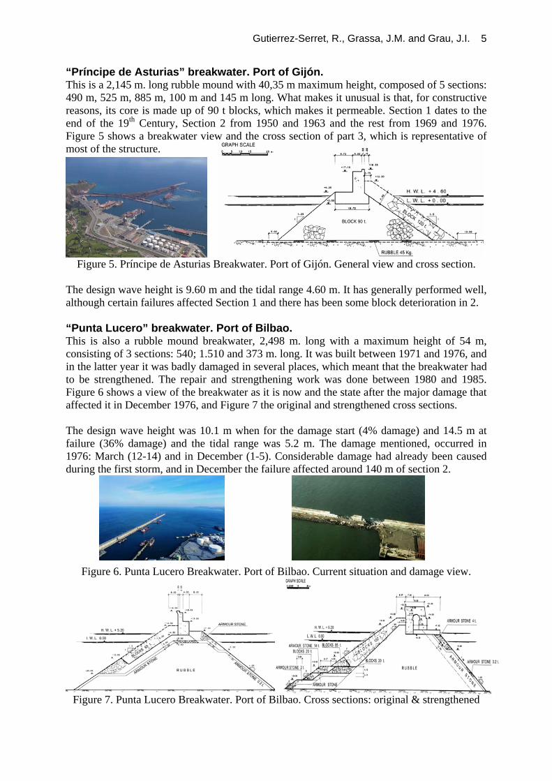
Figure 5. Príncipe de Asturias Breakwater. Port of Gijón. General view and cross section. The design wave height is 9.60 m and the tidal range 4.60 m. It has generally performed well, although certain failures affected Section 1 and there has been some block deterioration in 2. “Punta Lucero” breakwater. Port of Bilbao. This is also a rubble mound breakwater, 2,498 m. long with a maximum height of 54 m, consisting of 3 sections: 540; 1.510 and 373 m. long. It was built between 1971 and 1976, and in the latter year it was badly damaged in several places, which meant that the breakwater had to be strengthened. The repair and strengthening work was done between 1980 and 1985. Figure 6 shows a view of the breakwater as it is now and the state after the major damage that affected it in December 1976, and Figure 7 the original and strengthened cross sections. The design wave height was 10.1 m when for the damage start (4% damage) and 14.5 m at failure (36% damage) and the tidal range was 5.2 m. The damage mentioned, occurred in 1976: March (12-14) and in December (1-5). Considerable damage had already been caused during the first storm, and in December the failure affected around 140 m of section 2.
Figure 6. Punta Lucero Breakwater. Port of Bilbao. Current situation and damage view.
Figure 7. Punta Lucero Breakwater. Port of Bilbao. Cross sections: original & strengthened

Gutierrez-Serret, R., Grassa, J.M. and Grau, J.I. 6
The characteristics of both storms, which were established with the aid of a wave recorder installed in 1975, were: wave direction N48ºW for both events, significant heights (Hs) of 7.2 and 8.0 m. and average periods of 7.9 and 9.5 s, respectively. In view of the damage caused, several studies were undertaken to establish the causes of the failures and to strengthen the breakwater. It was found that the crown was unstable as from a wave height of 7 m and that the depth of the main armour layer (-10 m) was insufficient. “Los Llanos” Breakwater. Port of Tenerife. This is a 1,519 m long and 60 m high vertical breakwater, comprising 3 sections whose lengths are: 779; 710 and 30 m. It was constructed between 1971 and 1980 (sections 1 and 2) and between 1983 and 1987 (section 3). A view of the breakwater and the cross section of Section 2 can be seen in Figure 8.
The design wave height is 4.6 m and the tidal range is 4.6 m. It has performed well, no damage having been detected throughout its lifetime. However, in the construction, there was a severe storm on 16th January 1979, causing damage to 8 caissons that were laid but not filled.
Figure 8. Los Llanos Breakwater. Port of Tenerife. General view and cross section “Reina Sofía” breakwater. Port of Las Palmas. The total length of this rubble mound and vertical breakwater is 4,105 m and its maximum height is 58.30 m; it is composed of 3 sections, whose respective lengths are: 2,417 and 691 m. for rubble mound type and 997 for vertical. Rubble mound stretches were constructed between 1967 and 1972 (section 1) and 1975 and 1979 (section 2) and vertical between 1988 and 1991. Figure 9 shows a view of the breakwater and the vertical cross section, who was monitored in two sections (www. puertos.es/es/Monitorizacion_de_Obras_Maritimas).
Figure 9. Reina Sofía Breakwater. Port of Las Palmas. General view and cross section. The design wave height is 6.4 m and the tidal range is 2.7 m. It has performed well, no damage having been detected.

Gutierrez-Serret, R., Grassa, J.M. and Grau, J.I. 7
Breakwater for the enlargement to the Port of Gijón[5]. In view of the fact that the existing port was accommodating more traffic than it had been designed and there were draught restrictions on vessels, the Port Authority decided to enlarge the port by constructing an outer port close to the current one, to the east of Cape Torres. The new port consists of a 3,834 m long breakwater and a 1,250 m wharf with draughts from 23 to 27 m, which enables three 230,000 DWT bulkcarriers to berth at the same time. It will provide shelter for a water surface area of 145 ha and will have 145 ha of esplanades. Figure 10 shows the site of the new port and a photographic simulation of its final layout. The breakwater leads off from Cape Torres and is composed of 3 alignments, each with different typology: Torres Breakwater, North Breakwater and the Secondary Breakwater. The Torres Breakwater, 1,488 m long, is a rubble mound structure, lying at depths from 10 to 22 m, with a main armour layer of blocks from 10 to 145 t, the crown between elevations +14 and +24 m. Figure 11 shows a cross section of the final section of the breakwater.
Figure 10. Gijón enlargement. Site of the new port and photographic simulation of its layout.
Figure 11. Torres Breakwater. Cross section. The North Breakwater is vertical, comprising 33 caissons: 51.8 m long, 32 m wide and 32 m depth, the foundations lying at -24.75 m and crowned at +24 m. It is 1,593 m long and lies at depths from -25 to -30 m. Figure 12 shows a cross section of the structure. One zone of particular interest on the breakwater is the transition between the Torres Breakwater and the North Breakwater. The solution for this transition lies in the arrangement for two transverse caissons to the North Breakwater, protected by 200 and 90 t blocks. The maritime climate conditions for which the breakwater has been designed take into account storms from the NNW and the N, which has led to a significant wave height of 8.75 m for the Torres Breakwater and 9.50 m for the North Breakwater, with a 19 s peak period.

Gutierrez-Serret, R., Grassa, J.M. and Grau, J.I. 8
Figure 12. North Breakwater. Cross Section The Secondary Breakwater that leads off from the head of the North Breakwater is an 815 m long rubble mound with an armour layer of 90 t blocks. Each one of these sections was designed after conducting a large number of physical model tests in several EU laboratories. The CEDEX tested the Secondary Breakwater (Figure 13).
Figure 13. Secondary Breakwater physical model tests. CEDEX. The works were started in February 2005 and will be completed in October 2010. The Torres Breakwater was constructed in one complete section, mostly using marine resources; land resources -large dumpers and cranes- being used in the summer. Construction on the North Breakwater began by dredging the sandy seabed until rock was reached, after which the armour stone foundation for the caissons was performed, and the caissons themselves were constructed and sinked in their position; the latter operation proved to be one of the biggest challenges faced by these works, because it was the first time that such large caissons were placed in the Spanish Atlantic North Coast. Figure 14 shows different stages in the breakwater construction, which is now complete except for the crown.
October 2006 Summer 2007 Summer 2008
Figure 14. State of the works The entire construction and safety process has been planned on the basis of a wave prediction system (SAPO) developed specifically for these works; this forecasting system furnishes information about exceeding the thresholds: significant wave height (HS), peak period (TP) and wind speed, the progress on land works being determined by HS > 1.5 m

Gutierrez-Serret, R., Grassa, J.M. and Grau, J.I. 9
The works has withstood many storms with HS > 5 m, and in three such storms HS > 7 m was reached, one of which lasted for no less than 3 days. HS ~ 6,6 m y HMAXIMUM ~ 11.2 m, TP ~ 18 s and tide level of 5.5 m (Figure 15). The damage was kept under control in all of these storms, and it only affects the sections under construction and the temporary protection.
Figure 15.- Storms March 2007 and March 2008
Breakwater for the new Ferrol Outer Port[6]. The traffic growth predictions, together with the diversification strategy, played a decisive in the Port Authority’s decision to opt for new facilities, which have now taken the form of the current outer port, located at the entrance to the Ferrol estuary in the Cape Prioriño zone. The new port is composed of the following: a 1,040 m. long rubble mound breakwater with a 172 m long vertical spur breakwater close to its head, and a 1,515 m. wharf, with 857.8 m. constructed at the first stage, with a draught of 20 m. The facilities include 90 m. of esplanade. Figure 16 shows the site of the new port and an overview of it.
Figure 16. Ferrol Outer Port. Location, layout and overview of the new outer port (2004) The breakwater is a rubble mound structure sloping 1.75H/1/V, with one single alignment of a main armour layer made up of 90 t blocks, the crown being at elevation +18 m. The head is also a rubble mound type of 90 t blocks, sloping 2H/1V and reaching a maximum depths of 32 m. There is also a 172 m spur breakwater close to the head, running at right angles to the breakwater; composed of caissons sunk at -15 m. Figure 17 shows cross section.
Figure 17. Cross sections of the breakwater

Gutierrez-Serret, R., Grassa, J.M. and Grau, J.I. 10
The shelter afforded by Cape Prioriño ensures that the design waves are from the W, with a significant wave height of 7.6 m and a peak period of 18 s, for a 280-year return period A series of 2D and 3D physical model tests were conducted as part of the design process (2D E: 1/43 and 1/15; 3D E: 1/38.5). Figure 18 shows the 2D test in the Large Wave Flume and the 3D test in the Multidirectional Wave Tank, conducted at the CEDEX.
Figure 18. 2D and 3D physical model tests. CEDEX. The works started in 2001 and were completed in 2004. Before the breakwater construction an auxiliary port was constructed with a 6 t. rubble mound breakwater and a 150 m wharf for the maritime activities, which made it possible the breakwater progress to elevation -8 m, after which the land works began with dumpers, bulldozers and cranes for laying the blocks in place. The breakwater has already withstood several storms with negligible damage. Figure 18 shows the block manufacturing yard, and figure 19 the crane laying the blocks in place and a close-up of the crown construction work.
Figure 19. Block manufacturing yard and crane laying blocks. Breakwater for the new Coruña Outer Port[7]. A lack of sea and land space in the current port site, which encroaches upon the urban area, with environmental problems and the need to remove the petroleum products pipelines between the port and the refinery (3 km from the city), which cross it underground, meant that in the 1990s, the Port Authority considered to enlarge the port beyond the confines of the city. After a series of studies, a decision was taken to locate the new port at Punta Langosteira, 8 km to the southwest of the existing port. The new facilities were to be composed of: a 3,354 m. long rubble mound breakwater with a vertical spur breakwater lying at 391 m. to its head, a 921.5 m. transverse wharf with a draft of 22 m and a 579 m. secondary breakwater, also rubble mound type. The new port will provide 230.5 ha of shelter waters and 143.5 ha of esplanades, mooring facilities on the breakwater for 9 200,000 DWT oil tankers and berthing facilities on the wharf for other goods. The mooring line could be extended with others 3,000 m wharf and 230 ha of esplanades. Figure 20, shows the site and a simulation of its layout.

Gutierrez-Serret, R., Grassa, J.M. and Grau, J.I. 11
Figure 20. Coruña Outer Port. Site of the future port and simulated photo of its layout. The breakwater has 3 alignments, the first section and two on its main stretch. It will be a maximum of 40 m. deep and the crown is at elevation +25 m along the main section and at +19 m where it leads off. The breakwater head is vertical type 144 m. long, composed of 5 caissons, founded of -29 m, running at right angles to the centreline of the final stretch. A spur breakwater will be constructed along this stretch, composed of caissons founded of -26 m. Figure 21 shows the cross sections of the breakwater main stretch.
Figure 21. Main Cross sections of the breakwater. The contact between the main armour layer and the head is one peculiar area, 200 t blocks being used in this zone. Another singular zone is the armour layer for the sheltered area, where 150 t blocks with holes have been arranged between the head and the spur breakwater and 50 t blocks being used for the rest. The maritime climate conditions for which the breakwater has been designed are for a return period of 140 years, resulting in a significant wave height (HS)of 15.1 m. The way it is distributed throughout the length of the breakwater can be seen in Figure 22.
Figure 22. Extreme wave regime throughout the breakwater.

Gutierrez-Serret, R., Grassa, J.M. and Grau, J.I. 12
A series of physical model tests were conducted in several laboratories before the design was finally perfected. Where the CEDEX was concerned, 2D tests were carried out on the initial section (E: 1/45) and on the main section (E: 1/25 y 1/30), as well as 3D tests on the main section and the head (E: 1/60). Figure 23 shows the tests on the main section in the large flume and the 3D tests on this section and the head in the multidirectional wave tank.
Figure 23. Physical model tests, 2D and 3D. CEDEX. The works were initiated in March 2005 and they are scheduled to be completed in September 2011. The first two years were spent carrying out the groundwork: access, quarries, aggregate and concrete plants, block manufacturing yard and the construction of an auxiliary port, consisting of a rubble mound breakwater 503 m. long with 50 t blocks and a 350 m wharf. Figure 24 shows the block yard for the main armour layer and the auxiliary port.
Figure 24. Main block yard, cranes and auxiliary port.
The breakwater construction process is advancing from the sea, the core material being poured in guided by two retaining side moats, before being protected with 1 t quarry stones and 15 t blocks, over which the two layers of 150 t blocks for the main armour are laid. The aforementioned process is carried out with the use of two of the largest cranes in the world, which are able to lay 150 t blocks at a distance of 115 m.. The general advance of the breakwater is halted during the winter months. During this period only the barge carries on working, pouring in the core material and the quarry stones. Figure 25 shows how the works had progressed at different dates (2007, July 2008 and May 2009).
Final campaign 2007 July 2008 May 2009
Figure 25. State of the Works

Gutierrez-Serret, R., Grassa, J.M. and Grau, J.I. 13
One aspect concerning the construction process that must be stressed is the safety conditions under which it is taking place, to the extent that for a significant wave heights greater than 1.3 m, the activities on the breakwater work platform are halted. A specific wave prediction system (SPOL) has been developed for improving the security during the works. So far, the breakwater has fulfilled expectations where performance is concerned. The 1,600 m constructed in 2007 and 2008, have withstood several storms, particularly the ones that happened on 10th March 2008 and 20th January 2009, the first one reached the design wave level, without damage being detected. Figure 26 shows the breakwater during these storms.
Figure 26. Storms of 10. 03.2008 and 20.01.2009. Winter head protection zone. Breakwater for the enlargement to the Algeciras Port on Isla Verde. By 1990, the Algeciras port, in the south of Spain, overlooking the Straits of Gibraltar, and leading Mediterranean container port, was finding it difficult to cope with the amount of traffic. To overcome this, a decision was taken to carry out the biggest enlargement plan in the port’s history, and this was in the zone known as “Isla Verde” (Figure 27). This enlargement consists of a 2,060 m long vertical detached breakwater, which provides shelter for two wharves: the North Wharf -680 m de long with a draught of 17.5 m- and the East Wharf -1,540 m long with a draught of 18.5 m-. There is also a rubble mound breakwater on the south side, 890 m long, which has a 100 Ha esplanade.
Figure 27. Enlargement to the Port of Algeciras at Isla Verde. Layout and general views. The detached breakwater is a vertical structure comprising 43 anti-reflective caissons with one single alignment, separated 413 m from the East Wharf, laid on an armour stone foundation at -35 m and crowned at +7.5 m, with the seabed at depths from -43 m to -28 m. The top of the caisson cells and the crown cells serve to reduce the reflection level, the first row of these cells being open, in order to dissipate the incident wave energy, thereby reducing the wave reflected. A cross section can be seen in Figure 28. A return period of 275 years was taken when designing the breakwater, which yielded a significant wave height of 4,8 m and a peak period of 9 s. and SSE direction.

Gutierrez-Serret, R., Grassa, J.M. and Grau, J.I. 14
Figure 28. Cross section
Several physical model tests were developed at the CEDEX when designing this type of ant-reflective typology. Reductions of 60% being obtained for the coefficient of reflection for short periods (less than 8 s.) and wave heights ranging from 0.5 m to 1 m, reductions of 40 to 20% being obtained for more severe waves (Figure 29).
Figure 29. 2D Physical Model Tests. CEDEX. The works commenced in 2006 and have now been completed. Figure 30, shows how far the works had progressed in September 2006 and their current state finished.
Figure 30. Enlargement construction stages. It has withstood a storm from the east, on 11th October 2008, causing a deep-water wave height of 7 m reaching the breakwater at 3 m. The only damage to the structure being slight settlement (less than 10 cm) affecting the caissons. Breakwater for the enlargement to Cartagena Port in Escombreras. The Port of Cartagena, on the South-East Mediterranean Coast of Spain, is composed of two basins, one located within the Bay of Cartagena and an external one -the Escombreras Basin- which caters for most of the traffic, mainly liquid and solid bulk. By the 1990s it was becoming difficult to accommodate the traffic, so the Port Authority decided to enlarge it.

Gutierrez-Serret, R., Grassa, J.M. and Grau, J.I. 15
The enlargement took the following form: a 2,157 m breakwater and a 900 m wharf with a draught of 20 m. This enlargement served to increase the land area by 60 ha and provided 70 ha shelter waters. Figure 31 shows an overview of the port and of the Escombreras Basin.
Figure 31. General view of the port and view of the Escombreras Basin. The breakwater is composed of 4 sections, the maximum depth being 52 m. The main characteristics of the structure are as follows: − Initial section: a 202 m long mouth rubble structure with an armour layer of 45 t. blocks. − Southern Breakwater: a 401 m long vertical structure, comprising 10 caissons: 43.5 m
long, 18.5 m wide and depths ranging from 11 to 19 m. − Perimeter Breakwater: this 518 m stretch surrounds a small islet -the Escombreras Islet-,
that for it environmental value, a decision was taken to conserve it, and a channel being laid around it. The breakwater is vertical made up of 12 caissons (43 x 10 x 9 to 13 m).
− South-West Breakwater: 1,038 m long, composed of 20 caissons whose lengths range from 43.5 to 66.85, 26 m wide and depth of 29 m (Figure 32).
Figure 32. South-West Breakwater. Cross section The maritime climate conditions that were taken when designing the breakwater were for a significant wave height of 8.1 m and a peak period of 13 sec. A series of physical model tests were conducted to perfect the final design for the breakwater. The test on the Perimeter Breakwater of the Escombreras Islet can be seen in Figure 33.
Figure 33. 3D physical model test for the Perimeter Breakwater Escombreras. CEDEX. The works began in 2001 and are completed. Figure 34 shows the works completed and different construction stages.

Gutierrez-Serret, R., Grassa, J.M. and Grau, J.I. 16
Figure 34. View of the final configuration and construction states. Since it was completed it has withstood several storms without damage, the worst one taking place in December 2005, with a significant wave height of 5 m and a peak period of 9 s. Breakwaters for the enlargement to the Port of Barcelona. Towards the end of the 1980s, the Port Authority in order to overcome the following problems: to cater for the increasing growth in traffic, the growing number of vessels and their greater draught, to meet the demand for new land surface areas and to find an acceptable solution for the port-city relationship, devised the “Delta Plan” for the port development. Apart from enlarging the Port, the main activities also included diverting the River Llobregat, enlarging the airport (both lying to the south of the port), increasing the logistics activities area and creating new road and rail infrastructures. The port enlargement works, which began in December 2001, involve the construction of two breakwaters: the 4,800 m. long Southern Breakwater and the 2,170 m. long Eastern Breakwater, both now completed; a container terminal with 1,500 m. of mooring facilities and a minimum draught of 16 m, as well as other mooring facilities, thereby increasing the land surface area by 208 ha. Figure 35 shows a view of the enlargement.
Figure 35. Barcelona enlargement Port. General view and layout. The breakwaters lie in maximum depths ranging from 23 to 27 m. However, it was necessary to take into account the important fact that the seabed has a low bearing capacity, there being a 50 to 70 m layer of soft silt and soft silty clay overlying the rock stratum. The Southern Breakwater (4,800 m) has been split into three Stretches: − Stretch 1 (2,000 m): it is of the rubble mound type, with a main block armour layer from 8
to 60 t, depending on the direction of the storm and its angle of incidence, the crown being at elevation +12 m. Extensive armour stone foundations have been positioned on either side to guarantee stability against the risk of sliding (Figure 36).
− Stretch 2 (1,700 m): is vertical type, 47 caissons -33 m wide and 21,5 m depth- founded on an extensive 73 m wide armour stone, whose crown is at elevation +12 m (Figure 37).

Gutierrez-Serret, R., Grassa, J.M. and Grau, J.I. 17
Dredging and quarry run refill
Quarry run
Quarry run
3t. stones
6t. stonesO,2 t. stones 1,5t. stones
Blocks 8-60 t blocks
Figure 36. Southern Breakwater, stretches 1 & 3 and Easthern Breakwater. Cross section.
Figure 37. Southern Breakwater. Stretch 2. Cross section.
− Stretch 3 (1.100 m): is of the rubble mound type, with a main armour layer composed of
40 t blocks at its trunk and the head being formed with two caissons. The Eastern Breakwater (2.165 m) is a rubble mound structure whose foundation was laid in direct contact with the seabed, after a 3 m thick trench had been dredged. The main armour layer is composed of 50 t blocks The maritime climate conditions for which the breakwaters were designed were for a significant wave height of 7.6 m along Stretch 2 (vertical) of the Southern Breakwater and 7.3 m along Stretch 3 (rubble mound) and for the Eastern Breakwater, a peak period of 13 sec. being adopted. A large number of 2D and 3D physical model tests were conducted in CEDEX for the design of both breakwaters and for the construction stages (Figure 38).
East & South South 1 South 2 Figure 38. Physical models. Eastern & Southern Breakwaters and Eastern construction stage.
The low bearing capacity of the seabed foundation[9] -silts and clays- (Figure 39), meant that it was only possible to increase it strength, to make feasible to construct the breakwaters, by consolidating the seabed and dissipating the pore pressures, which was brought about by loads transmitted as the breakwaters were gradually being constructed. Instruments were placed in 8 sections -4 for each breakwater-[10] (Figure 39) to ensure that construction was consistent with design. The parameters measured were: settlement, lateral deformation and pore pressure.
Rubble

Gutierrez-Serret, R., Grassa, J.M. and Grau, J.I. 18
0
-10
-20
-30
-40
-50
-60
-70
-80
-110
-90
-100
East Breakwater South Breakwater
Upper layer ofsilty clay
Intermediate layer ofsand and gravel
Lower layer ofclay
Lower layer ofsand and gravel
20 m. water depth20 m. water depth
> 40 m. of silty clay> 40 m. of silty clay
Figure 39. Seabed foundation profile and instrumentation for the rubble mound breakwaters. The construction stages, as it were mentioned, was conditioned by the poor quality of the soil foundation, in such a way that is was necessary to accomplish it in several stages for the soil consolidation. Figure 40 show several construction operation.
Dumping barge Crane blocks placement Caisson sinking operation Figure 40. Breakwaters construction stages.
Acknowledgements We would like to thank the organisers of this Conference for invitation to present this paper. Likewise, we would to thank the Organismo Público Puertos del Estado and the Port Authorities referred to in the text, for the information received to enable prepare this paper. References [1] CEHOPU (1994). Puertos Españoles en la Historia. Centro de Estudios Históricos de
Obras Públicas y Urbanismo. CEDEX. Madrid, Spain. [2]Hormigón y Acero (2002). El dique flotante de Mónaco. Journal “Hormigón y Acero”,
year 2002, nos 223 to 226. (www.e-ache.net), Madrid, Spain. (In Spanish) [3] ROM. Maritime Works Recommendations. Puertos del Estado, Madrid, Spain
(www.puertos.es) [4] MOPU (1988). Diques de abrigo en España, Volumes 1 and 2. Ministerio de Obras
Públicas y Urbanismo. Madrid, Spain. [5] Díaz Rato J.L., Moyano J. y de Miguel M. (2008). Extension to the Port of Gijón, Spain.
Maritime Engineering, ICE, Volume 161, December 2008, pp. 153-186. [6] Grassa, J.M. et al. (2009). Ferrol Outer Port: experimental and in situ design studies.
Maritime Engineering, ICE, Vol 162, June 2008, pp. 57-72. [7] Noya, F. (2008). New Port Facilities at Punta Langosteira, Spain. Maritime Engineering,
ICE, Vol. 161, September 2008, pp. 101-106. [8] Castro, d and Cebrián, J. (2003). Ampliación de la dársena de Escombreras.Revista de
Obras Públicas, nº 150 (3430), pp. 39-46, Madrid, Spain. (In Spanish). [9] Puertos del Estado. Atlas geotécnico del puerto de Barcelona. Madrid, Spain. [10] Uzcanga, J. Et al. (2007). Case history – Instrumentation of Barcelona Harbour
breakwaters. On Course, PIANC, issue 127, May 2007.