Embed Size (px)
Citation preview

Agreement number: INEA/CEF/TRAN/M2014/1038613
Breakthrough LNG deployment in Inland Waterway Transport
Standardisation study on vessels • Activity 1.2 Development of standardised components for best available
LNG technologies; o 1.2.2 Dual fuel engines, mono fuel gas engines, LNG packs, tank
connection space, motor management system. Gas treatment system
• Activity 1.3 Defining a total configuration of a vessel-bunker station solution; vessel solution
• Activity 1.4 Adoption of the standard configuration by the competent authorities
Papendrecht; the Netherlands May 2019 Document history (Final Version / 14-05-2019) Contributing authors (See p.3)

2
Disclaimer The sole responsibility of this publication lies with the author. The European Union is not responsible for any use that may be made of the information contained therein.

3
Revision History
Revision Date Author Organization Description
V1 04-01-2018 Leon Sluiman Peter Snijders Arie Koedood Jaap Been Bram Kruyt Bert Kooijman Peter Vrolijk
ENGIE Pon Power Koedood Dolderman Wartsila Wartsila Kooiman
Processing draft document
V2 30-03-2018 Peter Snijders Pon Power Processing draft document
V3 30-04-2018 Peter Snijders Pon Power Processing draft document
V4 07-05-2018 Peter Snijders Pon Power Processing draft document
V4-V8 05-07-2018 Salih Karaarslan EICB/SPB Report structuring
V9 12-07-2018 Peter Snijders Pon Power Processing draft document
V10 19-07-2018 Bert Kooijman Wartsila Processing draft document
V11 06-11-2018 Koert van der Ploeg
Man Rollo Processing draft document
V12 26-02-2019 Peter Snijders Pon Power Processing chapters 6&7
V12 21-03-2019 Salih Karaarslan EICB/SPB Adding comments and restructuring chapters
Final Draft
14-05-2019 Salih Karaarslan EICB/SPB Incorporating final feedback and finalising document

4
Abbreviations
• TCS: Tank Connection Space
• ES-TRIN: European Standard laying down Technical Requirements for Inland Navigation
vessels
• CESNI: Comité Européen pour l’Élaboration de Standards dans le Domaine de Navigation
Intérieure
• SI: Spark Ignition
• GVU: Gas Valve Unit
• LNG: Liquefied Natural Gas
• NRMM Stage V: Non Road Mobile Machinery Stage V emission limits

5
Table of Contents
1 Introduction ...................................................................................................................... 7
2 Power source .................................................................................................................... 8
2.1 Dual Fuel engines ...................................................................................................................... 9
2.1.1 New dual fuel engines ........................................................................................ 9
2.1.2 Refit dual fuel engines ...................................................................................... 13
2.2 Mono Fuel engines ................................................................................................................. 17
2.2.1 Description of most common components .......................................................... 17
2.2.2 Standardization ............................................................................................... 18
3 Engine Room ................................................................................................................... 23
3.1 Engine room arrangements .................................................................................................... 23
3.1.1 Gas-safe engine room ...................................................................................... 23
3.1.2 Emergency Shut Down engine room ................................................................... 24
3.2 Standardization ....................................................................................................................... 25
4 LNGPac............................................................................................................................ 27
4.1 Description of most common components: ........................................................................... 29
4.1.1 LNG fuel tank .................................................................................................. 29
4.1.2 LNG Tank connection space............................................................................... 30
4.1.3 Bunkering station ............................................................................................ 31
4.1.4 Heating Media system ...................................................................................... 32
4.2 Variable on-board LNG volumes ............................................................................................. 33
4.3 Standardization ....................................................................................................................... 34
4.4 Certification ............................................................................................................................ 34
5 Vessel Integrated Design .................................................................................................. 35
5.1 Description of most common components ............................................................................ 35
5.2 Standardization ....................................................................................................................... 36
5.3 Certification ............................................................................................................................ 36
5.4 Configurations ........................................................................................................................ 37
6 LNG Configurations .......................................................................................................... 39
6.1 Gas-electric (LNG Hybrid) configuration ................................................................................. 39
6.1.1 Engine ............................................................................................................ 39
6.1.2 LNG fuel tank & corresponding equipment .......................................................... 40
6.1.3 Engine room .................................................................................................... 40

6
6.1.4 Standardisation and certification ....................................................................... 40
6.2 Dual-fuel engine configuration ............................................................................................... 41
6.2.1 Engine ............................................................................................................ 42
6.2.2 LNG fuel tank & corresponding equipment .......................................................... 43
6.2.3 Engine room .................................................................................................... 43
6.2.4 Standardisation and certification ....................................................................... 43
6.3 Dual-fuel vessel configuration ................................................................................................ 44
6.3.1 LNG fuel tank & corresponding equipment .......................................................... 46
6.3.2 Engine room .................................................................................................... 46
6.3.3 Standardisation and certification ....................................................................... 46
6.3.4 Rationale behind the dual fuel vessel ................................................................. 47
7 Description of the typical inland waterway vessel ............................................................ 49
7.1 Introduction ............................................................................................................................ 49
7.2 The Typical Inland Water Way vessel ..................................................................................... 49
8 Scenario’s for LNG configurations in the typical IWW vessel ............................................. 53
8.1 The Dual Fuel Engine Inland Water Way vessel ..................................................................... 53
8.2 The complete Gas Vessel ........................................................................................................ 55
8.3 The electrical System .............................................................................................................. 56
8.4 Energy Storage Solutions ........................................................................................................ 56
8.5 The Dual Fuel Vessel ............................................................................................................... 58
8.6 Other engine Options ............................................................................................................. 62
8.7 Other Manufacturers .............................................................................................................. 63
8.7.1 Spark Ignited alternatives ................................................................................. 63
8.7.2 Dual Fuel Alternative ........................................................................................ 64
9 Ex-ante Evaluation of Technologies .................................................................................. 66
9.1 Comparison of vessel technologies ........................................................................................ 66
9.2 Pay-back Period ...................................................................................................................... 70
10 Conclusion....................................................................................................................... 71
7
1 Introduction This study partly covers sub-activities 1.2, 1.3 and 1.4, ‘the development of standardized components for best available LNG technologies’, ‘Defining a total configuration of a vessel-bunker station solution’ and ‘Adoption of the standard configuration by the competent authorities’, respectively. Partly, because the scope of this study covers the vessel. The studied components and the configuration are therefore only relevant for the vessels. The study to standardized components and total configuration for bunker stations is covered in a separate study. The studied components are dual fuel engines, mono fuel gas engines, LNG packs, motor management system and gas treatment system. The fuel tank container (either containerised or non-containerised), its compatibility with other systems and the Tank Connection Space (TCS) is extensively discussed in the sub-report ‘LNG fuel tank, TCS and technical compatibility’. The objective of the vessel part of activities 1.2 , 1.3 and 1.4, is the completion of a study regarding standardisation and certification of the most common components for newly build or retrofitted IWT vessels, the integration of these individual components into a vessel configuration and the adoption of the configuration by the competent authorities.

8
2 Power source The studied power source for the propulsion of the vessel consists in essence of two options, which are alternatives to each other:
- Dual-fuel engine(s) o New o Refit
- Mono-fuel engine(s)
Source: own elaboration As can be seen from figure 1 the power source is located underdecks in the engine room in the ship’s aft. Obviously, the integration of the power source in the engine room and the vessel, will be in line with the conditions in relevant regulations and provisions, such as ES-TRIN.1 Chapter 4 ‘Vessel integrated design’ will provide more information on this. The sub-chapters hereafter will discuss the dual-fuel and mono-fuel options in more detail.
1 https://www.cesni.eu/en/documents/es-trin-2017/
Figure 1: Power source for propulsion in inland vessel

9
2.1 Dual Fuel engines
2.1.1 New dual fuel engines
2.1.1.1 Description of most common components Wartsila is currently the most prominent player in the IWT sector concerning dual-fuel engines. As a dual fuel engine, the Wärtsilä 20DF engine is designed for continuous operation in gas operating mode or diesel operating mode. For continuous operation without reduction in the rated output, the gas used as main fuel in gas operating mode has to fulfil the below mentioned quality requirements. The section below will enumerate the components of the engine.
Source: own elaboration
Figure 2: Wartsila dual-fuel engine

10
Cylinder heads Special shaped piston.
Pilot fuel system The pilot fuel injection system is used to ignite the air-gas mixture in the cylinder when operating the engine in gas mode. Figure 3: Pilot fuel injection system
Source: own elaboration
Gas admission valve The gas admission valves (one per cylinder) are electronically controlled and actuated to feed each individual cylinder with the correct amount of gas. The gas admission valves are controlled by the engine control system to regulate engine speed and power. Figure 4: Gas admission valves system
Source: own elaboration

11
Gas common rail pipe The gas common rail pipe delivers fuel gas to each admission valve. The common rail pipe is a fully welded double wall pipe, with a large diameter, also acting as a pressure accumulator. Feed pipes distribute the fuel gas from the common rail pipe to the gas admission valves located at each cylinder Figure 5: Gas common rail pipe
Source: own elaboration
Power measurement flange In mechanical propulsion applications, a torque meter has to be installed in order to measure the absorbed power. The engine power measurement flange is installed between the gearbox hub and flexible couplings. In gas mode, the measurement is used by the engine control system.
GVU-EDTM (Gas Valve Unit Enclosed Design) Before the gas is supplied to the engine it passes through a Gas Valve Unit (GVU). The GVU include a gas pressure control valve and a series of block and bleed valves to ensure reliable and safe operation on gas.
WOIS (Wärtsilä operator interface system) The WOIS is a tool developed by Wärtsilä to give the operator/service personnel information needed for trouble shooting, analysing and maintenance of a dual fuel engine. The WOIS gathers and logs data from all engines. The data is then presented by several display pages. Process displays are graphic pictures with measuring values and status information of the equipment in the dual fuel system. The process displays include common as well as individual engine related views. A trend display is available for each analogue value. Parameters measured and monitored are also presented in alarm and event list format

12
2.1.1.2 Standardization of Dual Fuel engines The basic Wartsila Dual Fuel Engine is of a standard design, type approved by all major classification societies. Available in power ranges from 900kW upwards. Auxiliary systems and configuration of all components on board may be adapted to the project specific vessel.
2.1.1.3 Certification All Wartsila DF Engines are type approved. Auxiliaries do meet the requirements of all major classification societies and are supplied with the appropriate Classification Certificates.
Source: own elaboration
Figure 6: Type approval certificate Wartsila DF engines

13
2.1.2 Refit dual fuel engines
2.1.2.1 Motor Management system for Dual fuel refit engines
2.1.2.2 Description of most common components A new motor management system (ECU) has been developed for a multipoint injection gas supply system, for use in existing engines that can be rebuilt for dual fuel purposes, starting with a Caterpillar engine type 3500, an engine type with a relatively large share in the sector. There are approximately 1200 type 3500 engines installed in the Dutch IWT sector alone. This solution can therefore, based on its technical and market potential, be regarded as a high potential SME innovation in the IWT sector. Besides the ECU it comprises the following new developed items :
• Micropilot, parallel on the main pilot, to ignite the gas mixture.
• Combustion pressure sensor in the combustion chamber
• Double-walled gas line on the engine
• Double-walled gas injectors. The test site includes a Caterpillar diesel of the 3500 type, a 800 kw generator and a 1000 kw loadbank. No changes of pistons, liners or valves has been made on the engine. This ECU uses the latest technologies to come to a diesel replacement ratio up to 98%, depending on the required emissions. The emission results in NOx and CH4 meet the current (2017) standards. Achieved efficiency, + 10 to 15 % , compared to the diesel version of this engine. The ECU is a 100% redesign of the original CAT Adem system, with all features like J1939 canbus communication and other on board instruments and OBD (On Board Diagnostics). The extra features of the ECU in combination with CPBC (Combustion Pressurebased Control) allows us to operate on both diesel only as well as dual fuel to a maximum of 99 % LNG. The CPBC detects possible causes for failure of an engine running on LNG, such as: -knocking, blowby, auto ignition, Pmax, Dp/Da. Basically, due to the CPBC the engine is maximal optimised per cylinder as far as engine safety, fuel economy, lifetime, emissions, cylinder balancing and alternative fuels like Bio LNG and H2. The resulting Arenared Caterpillar 3500 dual fuel engine can be seen in the picture below.

14
Figure 7: Arenared Caterpillar 3500 dual fuel engine
Source: own elaboration
The basis ‘Cat 3512’ engine is reengineered with the double-walled gasrail in grey as the best visible result on top of the engine.
15
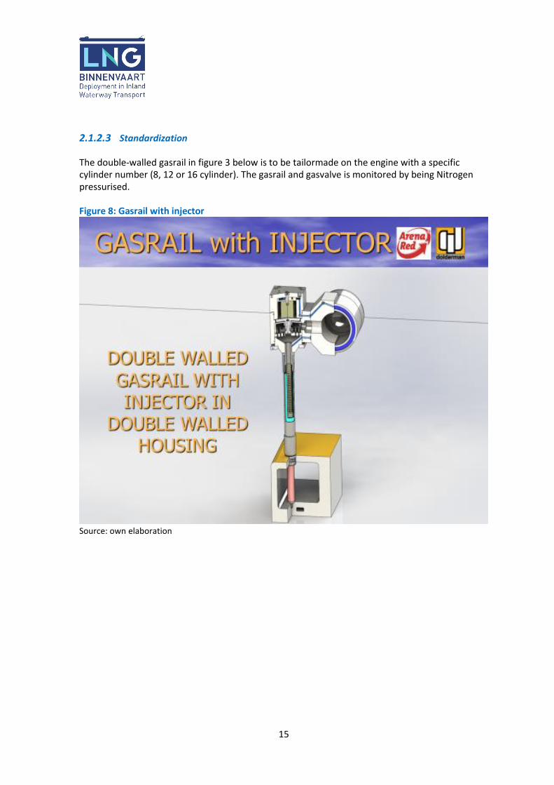
2.1.2.3 Standardization The double-walled gasrail in figure 3 below is to be tailormade on the engine with a specific cylinder number (8, 12 or 16 cylinder). The gasrail and gasvalve is monitored by being Nitrogen pressurised. Figure 8: Gasrail with injector
Source: own elaboration

16
2.1.2.4 Certification The ECU and above mentioned items are developed under supervision from Lloyd’s Register EMEA, Engineering Systems, Southampton, resulting in a:
• Machinery General Design Appraisal
• Arenared Caterpillar 3500 family, dual fuel (gas/fuel oil) Engine Conversion Figure 9: Design appraisal document
Source: own elaboration

17
2.2 Mono Fuel engines
2.2.1 Description of most common components Mono fuel marine engines are currently available from the following brands: Mitsubishi, MAN Rollo, Scania, Rolls Royce Bergen, Siemens and Caterpillar in the marine industry. Beyond the marine industry, brands like MAN Diesel and Turbo, Jenbacher and Waukesha are active in industrial markets, but out of scope for this topic. The Mitsubishi engines are demonstrated since 2000 in Norway with ferries. From there the engine are installed in other ferries and seagoing vessels. For Inland Waterway this engine will fit as well. The power range that can be used for the IWW from 300 kW up to 1.500 kW and approved by DNV-GL and BV. MAN Rollo has several engines available up to 530 kW since 2014. These engines are used in auxiliary generator sets providing electrical power for a sea-going ferry operated in Germany (MS Helgoland, DNV-GL). Similar generator sets are also used to power the hopper dredger Werkendam (BV). Among others, Scania engines driving generator sets up to 329 ekW have been applied in several in-land shipping projects, such as the Damen Ecoliner and the Stream vessels. The main projects have been realized with DNV-GL, BV and LRS. Dedicated Mono Fuel engines have the advantage of lower engine-out emissions compared to diesel and dual fuel engines. Especially on nitrogen oxides (NOx) and Particulate Matter (PM) emissions these engines achieve lower levels without the need for a particle filter or other complex aftertreatment systems. This makes them a sound alternative for reaching the new NRMM Stage V emission limits. This also applies to the dual fuel engines of Wartsila and the retrofit solution of Arenared, since both options meet the Stage V emission limits. Most Mono Fuel engines are characterized by a lean-burn combustion principle for achieving the optimum balance between fuel consumption and low exhaust emissions. Lean-burn operation is realized via an excess of combustion air, typically ranging from excess air ratio λ = 1.5 … 2. Ignition of the gas-air mixture in the combustion chamber is achieved by means of a spark plug, while the throttle valve is used to control the admission of mixture to the engine, hence controlling load and speed. Typical components include a common, central gas mixer or gas injection location, turbocharger(s) and mixture cooler. Designs can include 2 or 4-valve cylinder heads with conventional or overhead camshafts. Depending on the dimensions of the engine, additional safety devices may be installed related to the use of gas as a fuel. Such devices may include pressure relief valves, burst discs and oil mist detection. Besides clean combustion, Mono Fuel engines are characterized by challenging load acceptance and load dump/shunt. The reason for this is related to a tight gas-air ratio window in which a mixture is ignitable in conjunction with the inertia of the turbocharger’s rotating internals. In

18
contrary to a diesel or dual fuel engine, this results in a less responsive engine. As a result and depending on the application, special requirements need to be considered for the design of the electric system. Another challenge is, contrary to diesel fuel, the absence of a fixed LNG fuel specification, though engine manufacturers have minimum requirements in place. The benefit of having a redundant fuel system on an engine, like for dual fuel engines, is not present. Gas must be available to operate the engine.The challenges of a mono fuel engine are that they cannot be made gas-safe by means of double wall piping due to the compactness of the engine combined with the common gas inlet. This results that the engine room needs to be adapted according to class rules to make them safe in case of a single accident. Another challenge is that the gas engines are a bit less responsive as it comes to load response and shunts. The engines listed above have a lot in common to standardize. They are all gas-electric propulsion engines or auxiliary, intended for Emergency Shut Down engine rooms and require the same pressure range and classification.
2.2.2 Standardization
2.2.2.1 Gas Electric Propulsion Most Mono Fuel gas engines are designed and optimized to operate at fixed engine speed (1200, 1500 or 1800 rpm). Due to the fixed speed and the dynamic limitations of a Mono Fuel gas engine, most engines don’t allow for direct drive of a conventional propeller. Mono Fuel gas engines are more suitable for driving generators, while propulsion is arranged by means of electric motors driving propellers: Gas Electric Propulsion. In general, such configurations contain multiple LNG fuelled generator sets. The benefits of Gas Electric Propulsion include: 1. A common, scalable and hence efficiently operating power source depending on the power
request 2. Power also available for other components (hotel, crane, cargo pumps etc.) 3. Redundancy, including relatively easy integration of emergency power 4. Possibility to influence load steps and shunts by means of a properly designed power
management system Alternative designs, such as the MAN Rollo supplied MS Helgoland, include boosting of the main propulsion line by means of electric motors installed on a power take-in of the gearbox. A set of three Mono Fuel generator sets provides both the power for the boosting of the Dual Fuel engine driven main propulsion shafts, as well as providing power for hotel load and auxiliaries. Gas Electric Propulsion can be realized in different ways, each with its own pros and cons: 1. Conventional AC grid 2. DC bus

19
The conventional AC grid requires generators to operate synchronized at fixed speed within a tight bandwidth. Though proven and relatively cost effective, such set-up poses challenges on dynamic behavior and proper load sharing. The DC bus design incorporates frequency converters to convert AC generator voltage to DC bus voltage. Though increased complexity and cost, such configuration allows generators to operate in a wider speed range and unsynchronized. Additionally there is a possibility to introduce DC energy accumulators (batteries, super capacitors).
2.2.2.2 Engine Control Systems To allow a mono fuel engine to be operated in a stable and safe way, several control systems are required: 1. Ignition system 2. Speed governing system 3. Air-fuel ratio control system 4. Knock detection system 5. Misfire detection system Depending on the configuration, several of above systems may be integrated in one system. Currently, above systems are subjected to the rules of the classification societies and type approvals are required. Among others, this includes significant hardware testing as well as functional analysis of software algorithms. Issued type approvals for a certain project can be re-used for future projects with the same classification society. The ignition system is used for igniting the gas-air mixture in the cylinder at the requested ignition timing and with the requested spark energy. The system consist of a control box, sensors, a series of high-voltage ignition coils, ignition leads and spark plugs installed in the cylinder heads. A typical speed governing system consists of a control box, speed sensors and an actuator driving the engine’s throttle valve. The throttle valve of the engine controls the flow of gas-air mixture towards the engine and hence the load and speed. Speed control includes a dedicated speed setpoint and may include a droop characteristic and a ramp-up speed curve after start, as well as features to improve dynamic engine behavior. The air-fuel ratio control system is used to keep the air-fuel ratio in a certain range to guarantee a combustible gas-air mixture with stabile engine operation and acceptable exhaust gas emissions as a result. Dedicated control algorithms provide proper air-fuel ration during all operational conditions, varying ambient conditions and, within a certain bandwidth, changing fuel quality. The system consists of a control box, sensors and an actuator metering the gas supply. Detonation, also referred to as knocking, is characterized by the occurrence of additional, uncontrolled and explosively propagating flame fronts moving through the combustion chamber as a result of local high temperatures or pressures. Severe detonation in the combustion chamber of an engine may result in damage and engine break-down. A knock detection system is used as a safeguard to protect the engine from, if present, persistent detonation in the combustion

20
chamber and hence resulting engine damage. Among others, detonation can be the result of high combustion air temperatures or poor, low quality (methane number) fuels. A typical knock detection system consists of a control box and knock sensors. A dedicated algorithm is able to filter specific engine frequencies typical for detonation and ultimately will shut-down the engine. Additionally, misfire detection is applied to detect an incorrect combustion process. This safeguard is in place as, depending on the reason, an incorrect combustion may result in gas-air mixture in the exhaust system of the engine. A typical misfire detection system consists of a control box and speed sensors, performing an irregularity check on the rotational motion of the engine’s crankshaft.
2.2.2.3 Gas Valve Unit (GVU) Each engine is equipped with a separate GVU. The GVU has 4 main functions: 1. Reduction of pressure 2. Control of gas supply via Double Block and Bleed Valve 3. Providing safety devices 4. Monitoring of gas (temperature, pressure) Reduction of the pressure is realized via one or more pressure regulators. A typical GVU for engines equipped with a common inlet system, contains a zero pressure regulator to meter the gas flow towards the engine. Such regulator operates in conjunction with a full-flow venturi gas mixer installed in the combustion air inlet of the engine. The zero pressure regulator releases gas to compensate the vacuum caused by the combustion air flowing through the gas mixer. As engine load rises, combustion air requirement rises, vacuum in the gas mixer rises and the gas flow through the zero pressure regulator rises in an attempt to minimize the vacuum. Within a certain range, such system behaves rather linear, resulting in roughly the same air-fuel ratio at low load and high load. An electronic trim valve or variable gas mixer is used for precise gas flow control, enabling proper air-fuel ratio for stabile running and proper exhaust gas emissions on all engine operating points. Alternative gas supply systems operate without zero pressure regulator and venturi gas mixer. Admission of gas is arranged by means of a small amount of over-pressure, controlled by a pressure regulator, and an accurately controlled butterfly valve in the gas supply via a central mixing location in the engine’s combustion air inlet. Furthermore, a 2nd GVU operating at a higher pressure can be used in case the engine is equipped with a pre-chamber design. Such design includes a 2nd combustion chamber for igniting a rich, easily ignitable gas-air mixture. This resulting flame in the 2nd combustion chamber is used as a powerful ignition source for a very lean mixture in the main combustion chamber. Gas supply towards the engine is realized by a Double Block and Bleed Valve controlled by the generator set safety system. This part consists of 2 normally closed gas supply valves installed in series. The T-part between the valves is equipped with a normally open bleed valve connected to the vessels’ vent mast. In case the engine is at stand-still and the 1st gas valve would leak, gas is automatically released to the vent mast as a safety precaution.

21
Safety devices consist of, among others, a pressure relief valve. Monitoring can be provided by means of sensors and/or pressure switches connected to the genset monitoring and safety system. The GVU is a significant part of the engine. Currently classification rules require use of steel, welded pipes, type approved components and a full acceptance test including a non-destructive survey.
2.2.2.4 Certification Though in general based on the IMO-IGF code, the biggest challenge for engine manufacturers is the different classification societies with their own set of rules and their own interpretation of these rules. At the same time, the knowledge about the subject and experience with gas as a fuel depends on the classification society and the individual surveyor responsible for the approval process. Furthermore, the rules have been developed based on relatively large, port injection fuelled engines. Typical Mono Fuel engines are relatively small and are equipped with common gas-air inlets and common gas mixer systems. Parts as used on large engines are hardly available for small engines. Therefore, the approval process of small engines sometimes requires a different approach with alternative, tailor-made solutions deviating from the rules. Besides additional efforts from engine manufacturer side on extra testing and preparing additional documentation, it also requires a different, open-minded approach from classification societies for such alternative approaches. In general, documentation and test results from earlier projects can be re-used for new projects or other classification societies. Though, additional information might be requested. Furthermore, each new project will be subjected to a certain level of project approval by the respective classification society, depending on the engine configuration. Additionally, electronic systems need to be type approved by the respective classification society. Though test results from the past can be re-used for approval by a different classification society, the cost for the type approval process are considerable. GVUs are subjected to individual acceptance and are also considerable part of the cost for classification. Concluding, amongst others the following certificates will originate from a project: 1. Project approval certificate (parts of documentation may be re-used for future projects) 2. Type approval certificate of engine for a particular classification society 3. If applicable and depending on the scope of the engine type approval: type approval for
individual equipment (i.e. electronic engine control systems etc.) 4. Exhaust emission certificate (CCNR II) These certificates will smoothen project approvals in future or can be re-used.

22
An example of a Type approval certificate for a MAN engine can be found in Figure 10.
Source: own elaboration
Figure 10: Example type approval certificate MAN E3262LE201

23
3 Engine Room Engine room design, arrangement and location, as well as equipment and systems installed, will vary somewhat depending on specific ship installation, but the main principles concerning gas safety and redundancy must follow the minimum requirements.
3.1 Engine room arrangements The engine room of an LNG driven vessel, either dual-fuel or mono-fuel, will diverge from the engine room of a conventional diesel driven vessel. There are two different arrangements applicable:
1. Gas-safe engine room 2. Emergency Shut Down (ESD) engine room
3.1.1 Gas-safe engine room The major difference between a gas-safe engine room and an ESD engine room is based on double walled gas piping. With a double-wall gas pipe configuration, the engine room is to be considered gas-safe space, according to ES-TRIN Annex 82. The basic safety philosophy is such that a single failure of the LNG fuel system may not lead to a gas leak in the engine room. The double-wall piping with certified safe ventilation is in place to comply. Additionally, in case such failure is detected, the gas supply to this part of the LNG system should be terminated automatically. There are no special requirements as to the location of auxiliary systems in the room, except for the Gas Valve Unit, which has single-wall gas piping, and must be installed in a dedicated compartment or enclosure. The master gas fuel valve should also be installed outside the engine room. The gas piping from gas feed system to engine room through enclosed spaces is fitted inside a ventilated duct with appropriate gas detection. The machinery spaces with double walled gas feed pipes are to be considered gas-safe. Therefore, electrical equipment inside the engine room doesn’t need to be certified Ex apparatus. A gas-safe engine room needs less modifications on the engine room itself, in case of retrofitting an existing engine room there is a need for installation of a double walled gas feed piping arrangement.
3.1.1.1 Double walled gas feed piping ventilation The annular space in double wall piping is ventilated artificially by under-pressure, created by ventilation fans. Such ventilation system is independent of the common engine room ventilation system. The air inlet to the annular space is located at the engine and the capacity of the system is
2 https://www.cesni.eu/wp-content/uploads/2017/07/ES_TRIN_2017_en.pdf

24
at least 30 times the enclosed annular space volume per hour. The ventilation air is to be taken from a location outside the engine room, through dedicated piping. In addition, the ventilation requirements from the project specific classification society is to be considered in the design. Special care needs to be considered regarding the ventilation outlets on deck and the appropriate hazardous zone identification.
3.1.2 Emergency Shut Down engine room The basic safety philosophy for Emergency Shut Down engine room design is based on permanent gas detection and, in case measured gas levels exceed a certain limit, termination of any potential ignition source as well as the gas supply to the engine room. In normal situations, the engine room is typically considered as a non-hazardous zone, while it changes to a zone 1 in case of gas detection. In case of retrofitting an existing diesel engine room with a single walled gas engine and piping, the following main modifications are to be considered:
1. Equipping the room with an additional, independent, redundant and certified safe type ventilation system
2. Thermal insulation of the wall between the engine room/tank and particular parts of the vessel
3. Equipping the engine room with gas alarm system, and fire alarm system 4. Installation of a safety system that terminates electrical power to potential ignition
sources and that shuts down the gas supply to the engine room 5. Redundancy of on-board power supply for propulsion and main auxiliary systems
Regarding the first point, ES-TRIN prescribes that the ventilation system of the engine room shall guarantee a sufficient capacity to ensure that the gross volume of air inside the room can be changed at least 30 times per hour. Under normal operation the engine room shall be permanently ventilated with at least 15 changes of the gross volume of air inside the engine room per hour.3 Ventilation needs to be installed redundant and performance monitored with gas supply shut down in case the ventilation is not performing properly. Depending on the design, an air-lock may be required to access the engine room. Additionally, in practice inlets and outlets of the engine room ventilation need to be carefully located. Location is of importance for proper fresh air flow distribution in the engine room but also on deck with respect to hazardous zone identification. There are no such regulations concerning ventilation of a conventional engine room enclosing diesel engines. As a result, it becomes necessary to install significant ventilation systems. Regarding the second point, in case the LNG fuel tank is installed in the hull of the vessel the wall between the engine room and hull should be insulated with Type A60 insulation, in order to create a flame-retardant effect. This means that temperature will not exceed certain limits within 60 minutes in case there is fire in the LNG fuel tank space.
3 https://www.ccr-zkr.org/files/documents/cesni/ES_TRIN_en.pdf (p.375)

25
The third point concerns the mandatory fixed gas detection system and fire detection system4.. ES-TRIN prescribes that smoke detectors alone are not sufficient for rapid detection of a fire. The fire detection system shall have the means to identify each detector individually. The gas safety system shall shut down the relevant parts of the gas supply system automatically upon fire detection via the safety system. The fourth point refers to the safety system. This system is connected to the gas detection system. In case the gas level exceeds a certain limit, the system should immediately terminate all electric power to non-certified equipment, which in practice includes the engines. Only equipment that is certified safe is allowed to continue operation, which typically includes lighting, gas detection system etc. At the same time, the safety system closes the gas supply towards the engine room, which can be realised via closing the Master Gas Valve. The fifth item concerns redundancy. In case the power delivered by the gas engines is essential from a safety point of view (e.g. as propulsion), it is important to consider redundancy for power generation. Depending on the configuration, multiple gas engines with multiple independent engine rooms may be necessary or alternatively diesel back-up generators. LNG tank room arrangements In case the LNG fuel tank is installed in the hull of the vessel the wall between the LNG tank room and hull should be insulated with Type A60 insulation, in order to create a flame-retardant effect. This means that temperature will not exceed certain limits within 60 minutes in case there is fire in the LNG tank room. The LNG tank room should be equipped with a suitable fixed fire alarm system. ES-TRIN prescribes that smoke detectors alone are not sufficient for rapid detection of a fire. The fire detection system shall have the means to identify each detector individually. The gas safety system shall shut down the relevant parts of the gas supply system automatically upon fire detection. Equipment for ventilation needs to be installed in the LNG tank room. The tank room ventilation ensures 30 air changes per hour, to remove any leaked gas. The ventilation system for this room consists of an air inlet line and an outlet line with an electrically driven ventilation fan. The equipment and the material of the ventilation system should be Ex approved.
3.2 Standardization Standardization of the engine room will be difficult while the characteristics of the room will depend on the vessel and engine type. For example, a Wartsila duel-fuel engine has a double-walled installation which enables an internal ventilation and significantly limits of an external gas leakage, while the engine will stop automatically in case of an internal gas leakage. The installation therefore limits the need for a significant external ventilation installation for the engine room.
4 https://www.ccr-zkr.org/files/documents/cesni/ES_TRIN_en.pdf (p.381)

26
Next, the type of vessel will also be of influence. For example, with motor tank vessels the LNG fuel tank can be placed on deck, making a special insulation on the wall between the engine room and hull not necessary. It will therefore not be possible to standardize the engine room on an overall level, perhaps on a component basis (e.g. type of ventilation installation).

27
4 LNGPac The LNGPac is basically the combination of an LNG tank and the Gas treatment system; related equipment, used for bunkering, storage of liquefied natural gas and for gas supply to the engines or other consumers. It is an alternative to the process of acquiring each individual component and their integration into one system. The sections below will shortly discuss the individual components of the LNGPac. A more in-dept discussion of each individual component can be found in the sub-report ‘LNG fuel tank, TCS and technical compatibility’. Figure 10 illustrates the locations on board of a vessel on which an LNGPac can be placed on, either underdeck or above, or even partially above and partially underdeck:
Source: own elaboration Remark: there are eight possible locations for a bunker station on board of a vessel. The LNG fuel tank and corresponding TCS can be placed on four different locations, in some cases it is possible to place it either underdeck or above deck.
Figure 11: LNGPac for inland vessel

28
The possibilities for placing a tank and its TCS, either (partially) above or underdeck, are illustrated in figure 11 below:
Source: own elaboration
The individual components are standardized as much as possible and their on board placement will also be standardized to a certain level, but this eventually depends on the specific type of vessel. Depending on the type of vessel an LNG fuel tank can for example be placed in the aft of the vessel or In-Bow. For motor tank vessels the deck will be the most practical place to put the fuel tank and TCS on, also the motor tank vessel has the most options for placing a tank and TCS. In contrary, the number of options are limited for a motor vessel carrying containers or dry bulk. It will not be possible to place the tank and TCS on deck. Furthermore, a location in the middle or front of the hull will also be difficult due to the piping, which then needs to go from the front of the vessel backwards to the engine. This is difficult to realize in a vessel carrying containers
Figure 12: Positions LNG tank and TCS

29
and/or dry bulk, while the piping would then need to be installed on the floor with containers and/or dry bulk on top of it. With a motor tank vessel the piping will simply be installed on deck. Concluding, there is not one but several standard locations to place an LNG fuel tank and its corresponding equipment. The number of possible locations will depend on the vessel type. However, factors like the distance between the wall of the craft and the LNG fuel tank will be independent of the type of vessel, while this is established in regulations and provisions. Chapter 5 ‘Vessel integrated design’ will provide more information on this.
4.1 Description of most common components: • LNG Tank
• LNG Tank connection space
• LNG Bunker station(s)
• LNG Hearting media skid
4.1.1 LNG fuel tank The LNG fuel tank is used to store the liquefied natural gas. The tank is a double shell vacuum and perlite or multi-layer insulated independent tank. The LNG fuel tank has one inner pressure vessel and one outer shell. The space, annular space, between the inner and outer vessel contains the vacuum insulation. Both the inner pressure vessel and the outer vessel are made of stainless steel (or other cryogenic steel). The outer vessel is equipped with a vacuum safety device which prevents any accumulation of pressure between the inner and the outer vessel. The tank is designed according to the IGC and IGF codes as well as classification and flag authorities’ rules and requirements. Characteristics of the ship and location of the tank are required inputs for the tank design. Figure 13: Stationary LNG fuel tank as part of an LNGPac
Source: own elaboration

30
4.1.2 LNG Tank connection space Tank Connection space; Tank Connection Space is a gas tight stainless steel space that is surrounding all the tank connections/penetrations to the LNG storage tank. The Tank Connection Space also contains cryogenic equipment such as evaporators, instruments and valves. The Tank Connection Space is welded to the LNG storage tank and is accessed for maintenance/inspection through a manhole/hatch. Figure 14: LNG tank connection space
Source: own elaboration

31
4.1.3 Bunkering station Bunkering station is usually the name of the compartment or area where the bunkering manifold is located on the ship. Included in the LNGPac system deliveries are the manifold flange, piping, valves, sensors and associated electrical boxes and control air cabinets. Other necessary arrangements needed for facilitating a safe LNG bunkering operation like doors, hull protection arrangements, gas detection systems and possible lifting equipment are not included in the standard delivery. Figure 15: Bunkering station
Source: own elaboration

32
4.1.4 Heating Media system The evaporators are heated by a suitable heating source, normally the cooling water system from the engines, using an intermediate glycol-water circuit. The heating system circulates the glycol-water mixture through the evaporators and keeps it at the correct temperature. The main components of the heating system are the circulation pumps, the heat exchangers and the expansion tank. The heat exchangers are used to transfer energy from the heating source to the glycol-water system. The expansion tank compensates for volume changes due to variations in temperature in the system. Figure 16: P&ID Heating Media system
Source: own elaboration
To ensure safety the pressure of the glycol system will be lower than the pressure of the LNG/NG, in case a leakage will of LNG/NG will take place the pressure of the glycol system will increase. The pressure increase will be measured by a pressure transmitter and will shut down the LNG fuelling system.

33
4.2 Variable on-board LNG volumes Variable on-board LNG volumes are referring to the arrangements on board which make variability in the LNG volumes, required for propulsion, possible. There are two factors which need to be taken into account for variability of LNG volumes on board of the vessel; the technical and legal factors. First, the technical aspect will be discussed. Variability of LNG volumes on board of the vessel can be realized, for example, through:
• Replacing the original stationary fuel tank by either a larger or smaller stationary fuel tank.
• Replacing the original stationary fuel tank by a larger or smaller containerized fuel tank.
• Replacing the original containerized fuel tank by either a larger or smaller stationary fuel tank
• Replacing the original containerized fuel tank by either a smaller or larger containerized fuel tank
• Adding additional fuel tank containers for extra volume In the case of a stationary fuel tank, it will be technically not a significant problem to replace a stationary fuel tank of a certain capacity with a stationary fuel tank which is smaller in size. However, the contrary will be difficult, if not impossible. Replacing a stationary fuel tank with a relatively larger fuel tank (e.g. from 40m3 to 60m3) will most likely have a negative impact on the stability of the vessel, while upon first placement of the tank the stability of the vessel will be calculated according to a tank capacity of 40m3. Regarding the TCS, it will not be necessary to replace it. However, the installation will require some fine-tuning in order to handle a divergent capacity. Replacing a stationary fuel tank with a containerized fuel tank of the same or smaller capacity will require some technical modifications on board of the vessel, in order to create a proper layer to put the fuel tank container on. Replacement with a fuel tank container which is larger in size will again result in stability problems, and is therefore technically not a preferred operation. The abovementioned reasoning also applies to replacements of containerized fuel tanks with stationary fuel tanks. A last point concerns adding additional fuel tank containers for extra volume, for example due to a fuel intensive sailing trajectory. Technically this should be possible with some modifications to the original installation. For example, two separate fuel tank containers next to each other could be connected with the TCS and engine by a T-piping construction. In addition to the technical aspect, there is the legal aspect. Unfortunately, it will be legally cumbersome if not impossible to implement abovementioned technical solutions into practice. Replacing an existing stationary fuel tank with another stationary fuel tank requires the supervision and approval of a classification society, which is a cumbersome and costly process. A third and last aspect is the economic one, which is especially a concern in the examples addressing a replacement of a stationary fuel tank with another stationary fuel tank. When these

34
fuel tanks are acquired through a conventional financial transaction instead of a leasing construction for example, the original fuel tank would have to be sold when a new larger/smaller one is acquired. The residual value may be significantly lower than the original purchase value, having a significant negative economic impact.
4.3 Standardization Since the Inland fleet is pretty well standardised, in particular vessels from 86m upwards, there is ample room for standardisation. About 80% of the propulsion system can be built-up out of standard modules; the remaining 20% is vessel specific (interfaces between propulsion system and vessel systems)
4.4 Certification For the standard Modules a Type Approvals could be obtained. However considering the 20% vessel specific elements, this is not the most cost effective solution. The complete system is built in accordance with the applicable rules and regulations and will be supplied with Class certificate.

35
5 Vessel Integrated Design
5.1 Description of most common components In the above paragraphs, the different components of the LNG Propulsion system are described on a modular level. Typically a shipyard is responsible for the installation of these components into the vessel. Furthermore the shipyard is responsible for the complete system integration, and verification thereof during a HAZID performed by an independent party (usually a Classification society such as LRoS or BV) The system integration can also be assigned to a 3rd party. The complete system is to be in compliance with:
• Classification Society Rules for the classification of Ships
• Classification Society Rules for the classification of Inland Waterway Ships and Rules for the Classification of Natural Gas Fuelled Ships
• ES-TRIN 2017
• Rhine Vessel Inspection Regulations (RVIR)5,6
• Directive 2016/1629 European Union7 List of installation works:
• Installation of bunker stations on board
• Installation of LNG Tank
• Installation of Tank Connection Space
• Installation of the water-glycol skid
• Installation of Gas Valve Unit l
• Installation of LNG Engine
• Installation of the Exhaust system, (often) including rupture disk and by-pass exhaust line.
• Supply and installation of all interconnecting piping in accordance with supplier’s diagrams. Note that most piping is of stainless steel, single wall outside the vessel (on deck) and double walled inside the vessel.
• Design, supply and installation of an extensive Ventilation system safe intake and outlet ducts at safe locations. Major outlet is the tank relief outlet duct that may releases substantial quantities of Natural Gas in case the pressure is not properly managed (protected by multiple alarms)
• Design, supply and installation of the water-glycol skid. This included the (often insulated) piping from the Engine’s cooling water system to the Tank connection Space
• Design, supply and installation of the pneumatic system to operate the gas valves
• Design, supply and installation of fire protection devices in tank- and Engine room, including insulated machine room walls.
• Design, supply and installation of a nitrogen gas system, to ventilate the LNG installation in case of malfunction or maintenance.
• Integration of all LNG system control system components, indicators, alarms etc into the vessels; electric system
5 https://www.ccr-zkr.org/13020500-en.html#05 6 ES-TRIN can be seen as the future successor of RVIR. RVIR refers together with EU Directive 2016/1629 to ES-TRIN (see: https://www.cesni.eu/wp-content/uploads/2018/05/5_Boyer_SUKTagung) 7 https://eur-lex.europa.eu/legal-content/EN/TXT/PDF/?uri=CELEX:32016L1629&from=NL

36
5.2 Standardization Possibilities to standardise the above installation works are limited as they are vessel specific. However the design activities can be standardised to a large extent and in case of, for example the typical 110m inland tankers, there is room for further standardisation. For example: the LNG systems designed for the Shell Inland tankers forms in principle the standard for 110m tankers.
5.3 Certification Regarding the certification, there is the certification of individual components at the one hand and the certification of the vessel on the other hand. All individual components to be used in a configuration of a vessel need to have a classification certificate (either a type approval or another type of certificate). The certification of individual components is something which needs to be arranged between the manufacturer and the classification society. Next to the individual components, the vessel (newbuild or retrofit) containing a total LNG configuration also needs to be checked and approved by the classification society (or a ‘commission of experts’, which is mostly a classification society). The structure of this process is summarized below and is also implemented for the pilot vessels in this Action:
• In case the vessel encompasses a completely new and innovative configuration, some first exploratory discussions will take place with the classification society in order to discuss the feasibility of the project. Classification societies for the IWT sector are Bureau Veritas, Lloyd’s Register and DNV-GL8.
• A second step, and the first step in the process with classification societies in case the step above does not apply, concerns the HAZID study. In order to perform the HAZID study a design needs to be drafted including a general plan, ventilation plan, P&ID and arrangement LNG system, propulsion and power generation concept, one line diagram for the electrical system, arrangement bunker manifold, hazardous area plan, etc. The HAZID study can start only after the mentioned documents are submitted and checked. During the HAZID the complete integrated system on board with all individual systems are being reviewed on risks and precautions taken to mitigate such risks. After a successful HAZID a design approval will be generated.
• The real engineering process will only start after a positive HAZID and the design approval. During this step the technical drawings and calculations will be submitted for review and approval.
• After the engineering is finished and approved the construction phase can start. This phase will be under the supervision of a classification society or expert.
• The whole classification process is completed by successful sea trials/testing phase of the vessel after which a Class Certificate for the complete vessel is provided.
8 https://www.ilent.nl/onderwerpen/klassenbureaus-en-keuringsinstanties-binnenvaart

37
5.4 Configurations Given the chapters above it can be concluded that not only one, but several standard configurations for vessels are possible. First of all, there are standardized individual components, which are in some cases competing. For example the options for the power source:
• Dual-fuel engines (new or retrofitted engines)
• Mono-fuel gas engines Next to inland vessels powered by dual-fuel engines, it is also possible to equip inland vessels with mono-fuel gas and diesel engines making it a dual-fuel vessel. Second, there is the LNG fuel tank and its corresponding equipment:
• LNG Tank (either a non-containerised or containerized tank, however containerized tanks are currently not available due to a lack of economic viability)
• LNG Tank connection space
• LNG Bunker station(s)
• LNG Heating media skid LNGPac is a complete solution of Wartsila, incorporating all four bulletpoints above. All the mentioned components are required on an LNG driven inland vessel, either new or retrofitted. However, the components can be placed on different locations depending on the type of vessel. A bunker station (refueling point) for example, can be placed on eight different locations on board of the vessel. Although the number of alternative locations for the individual components is not indefinite. Furthermore, the exact location of the component has to be in line with regulations and provisions. This concerns for example the distance between the wall of the craft and the LNG fuel tank, independent of the exact location of the tank and the type of vessel. So eventually, there are is limited number of standardized configurations, encompassing standard individual components and standard locations for these components. A formal approval by the classification society on the standardized configuration incorporating all the individual components on specific locations can only be acquired once it is built in the vessel. The whole classification process is completed by successful sea trials after which a Class Certificate for the complete vessel is provided. Therefore, the approvals on the integrated vessel design will be obtained after de deployment of the pilot vessels. Though, the coming chapters will discuss three standard configurations for LNG driven vessels. These three configurations are:
1. Gas-electric (LNG Hybrid) configuration
2. Dual-fuel configuration which is integrated in the pilot vessel ‘Somtrans LNG’
3. Dual-fuel vessel configuration which is integrated in the pilot dredging vessel
‘Werkendam’
Since the concept of ‘dual-fuel’ propulsion is from a sole technical point of perspective largely the
same for either new or retrofitted dual-fuel engines, the (retrofitted) dual-fuel configuration to be
deployed on the pilot vessel ‘Argonon’ is not added as an additional configuration to this chapter.

38
These three standard configurations will be applied on the pilot vessels in this Action, whether
these vessels are new or existing, motor tank/dry cargo or other type of vessels. Depending on
the exact type of vessel the total configuration may slightly differ in factors like the exact location
of certain components, size of tank, etc., but overall the total configuration will be the same.

39
6 LNG Configurations
6.1 Gas-electric (LNG Hybrid) configuration This chapter will discuss the gas-electric configuration yet to be deployed in this Action, which can be regarded as a standard gas-electric configuration for IWT vessels.
6.1.1 Engine The power source of the gas-electric (hybrid) configuration consists of a gas engine with a generator, also known as a gas generator set. The figure below illustrates a standard gas generator set of Mitsubishi, available in a power range from 300kW to 1500kW, and applicable for IWT vessels.
Source: Vento, R. and Boensma, R.; Mitsubishi Turbocharger and Engine Europe Remark: a gas generator set consisting of a Mitsubishi gas engine on the left part and Stamford generator on the right part with the following type description: ‘GS6R-MPTK MILLER CYCLE+STAMFORD HCM 534 E’
The gas generator set is approved by DNV-GL and BV. As explained in chapter 2.2, most mono fuel engines don’t allow for direct drive of a conventional propeller. The gas generator set powers an electric motor which in turn drives the propellers. So there actually occurs a conversion from thermal energy (gas engine) to electric energy (generator) to mechanical energy (electric motor). In case of a conventional diesel or dual-fuel propulsion the engines directly, through a gear, drive the propellers. So there occurs a direct conversion from thermal to mechanical energy.
Figure 17: Mitsubishi/Stamford gas generator set

40
6.1.2 LNG fuel tank & corresponding equipment An LNG fuel tank and its corresponding equipment (TCS, bunker station and heating media skit) are generic and will not vary much depending on the type of LNG configuration. It will merely depend on the type of vessel and its sailing trajectory, for example a relatively large vessel (e.g. 135m motor tank vessel) with an intensive sailing trajectory (Rotterdam-Basel) will require a relatively large fuel tank as compared to a smaller vessel (e.g. 85m motor dry cargo vessel) operating on relatively short distances. Furthermore, as discussed in chapter 4, the type of vessel will also be of influence regarding the possible locations of the tank and TCS. However, there is no gas-electric driven vessel foreseen yet in the Action. The final configuration including the exact characteristics and location of the fuel tank and its corresponding equipment is not defined yet.
6.1.3 Engine room In line with the paragraph above, the exact characteristics of the engine room will merely depend on the type of vessel. Though, given the fact the gas generator set discussed above has no internal ventilation, ventilation of the engine room needs to be strictly in line with the regulations.
6.1.4 Standardisation and certification Given its power range and maritime applicability, the certified gas-electric power source discussed above can be seen as a standard and is technically applicable to a diverse range of inland vessels. The certified LNG fuel tank and its corresponding equipment is relatively less ‘standardised’. As discussed in chapter 4 there a couple of standard locations available for the placement of the tank and its corresponding equipment. The final location and the exact characteristics will predominantly depend on the type of vessel and the preferences of the ship owner, based on its business model (e.g. operations on intensive trajectories may require relatively large fuel tank capacity). The same reasoning also applies for the engine room. As discussed in chapter 3, the characteristics of the engine room depends very much on the engine and the type of vessel. Having one standard engine room is therefore not possible. Consequently, having one standard for the total LNG-electric installation consisting of gas generator set, LNG fuel tank, TCS, bunker station and heating media skit and other minor components is not possible. About 80% of the propulsion system can be built-up out of standard modules; the remaining 20% is vessel specific. The final certification, i.e. the approval of classification society, of the total configuration in the vessel therefore always follows after the vessel deployment and successful trials. However, regarding standardisation, as stated in chapter 5 the design activities can be standardised to a large extent.

41
6.2 Dual-fuel engine configuration This chapter will discuss the dual-fuel engine configuration which will be deployed in this Action with the pilot vessel ‘Somtrans LNG’. This configuration can be regarded as a standard dual-fuel configuration for IWT vessels. The standard dual-fuel configuration for IWT vessels can be divided in standardized systems:
1. Wärtsilä 20DF Dual Fuel engine & gas valve unit 2. LNG tank, tank connection space, bunker stations & glycol heating media skid 3. Gas fuel feed piping
Below shown pictures indicate the basic standard configuration for a typical IWT tanker, meaning:
• Wärtsilä 20DF Dual Fuel engine & GVU in aft engine room • LNG tank including TCS inside the bow of the vessel • Bunker station located on forward side of the deck (starboard and/or portside), also
referred to as ‘LNG In Bow’ • Gas fuel feeding line to aft engine room running over deck • Warm water supply and return for LNG evaporators running over deck
Source: own elaboration
Figure 18: aft of the vessel

42
Source: own elaboration The configuration for the Somtrans vessel is based on the basic standard configuration and consists of the following components:
• 2x Wärtsilä 8-cylinder 20DF dual fuel engine (1.480kW @ 1.200rpm) • 2x Gas valve units (one per engine) • 1x 90m3 LNG tank with enclosed tank connection space • 2x bunkering station located on forward side of the deck (starboard and portside fuelling
possibilities)
6.2.1 Engine Wärtsilä 20DF is suitable for a wide range of applications. Thanks to fuel flexibility the engine can be installed and optimized for variable speed mechanical drives for main engine applications. The multi-fuel operation capability offers new machinery opportunities for various vessel applications. The compact and light Wärtsilä 20DF fits perfectly also as mechanical drive prime mover for smaller applications, such as IWT vessels. One of the main features of the proven dual-fuel technology is that the engine can be switched from fuel oil to gas operation or vice-versa. Transfer takes place automatically after the operator’s command without power interruption or instantly in case of a gas supply interruption. The natural gas is supplied to the engine through a gas valve unit, where the gas is filtered and gas pressure is controlled. The system includes the necessary shut-off and venting valves to ensure safe and trouble-free low-pressure gas supply. On the engine, the gas is supplied through a large manifold running along the engine. Each cylinder then has an individual feed pipe to the gas admission valve close to the cylinder head. Gas piping is of double wall design as standard. When running the engine in gas mode, the air / gas mixture is ignited with a small quantity of diesel pilot fuel. The amount of pilot fuel is optimized for best combustion by the embedded engine speed & load control and monitoring system. The advanced automation system provides complete engine safety system and local monitoring. Thanks to build-on complete automation integration the external control system is significantly reduced which obviously saves space in the engine control room.
Figure 19: bow of the vessel

43
6.2.2 LNG fuel tank & corresponding equipment The design of the LNG tank and tank connection space has been integrated into a solution where the LNG tank room itself will become a safe machinery space. The tank connection space is a confined area which is considered as a double walled space, the annular space in the tank connection space will be ventilated according the same principle as the Wärtsilä dual fuel engine and fuel piping system. This will result in a less strict LNG tank room design. The bunkering skids are designed of outside operation, the bunkering skids will be located on the forward side of the deck making bunkering possible on starboard as well on portside.
6.2.3 Engine room The design of the Wärtsilä dual fuel engines contributes in the engine room design, due to the double-walled design of the Wärtsilä 20DF dual-fuel engine and the gas fuel supply system. The engine room is designed as a gas-safe engine room, as described in Chapter 3.1.1.
6.2.4 Standardisation and certification The DF engine configuration on board of the ‘Somtrans LNG’ can be seen as a standard and is applicable to a large range of inland motor tank vessels. As explained in previous chapters, some aspects will be vessel specific, but the installed configuration in the ‘Somtrans LNG’ is to a large extent standard. The class certification will be provided after the whole classification process is completed by successful sea trials/testing phase of the vessel.

44
6.3 Dual-fuel vessel configuration This chapter will discuss the dual-fuel vessel configuration which will be deployed in this Action with the dredging vessel ‘Werkendam’. The dual-fuel vessel configuration can be regarded as a standard configuration for IWT vessels and consists of a combination of Mono Fuel gas generators combined with a diesel fuelled (back-up) generator. The vessel is a LNG fuelled crane hopper dredger of 68.4 m length and a hopper capacity of 700
m³. Electrical propulsion is arranged by means of rudder propellers and a bowthruster. The electrical driven crane is used for dredging, while electrical driven spudpoles provide additional stability during operation. Figure 20: LNG installation in green on bridge deck of Werkendam
Source: Neptune engineering
Figure 21: LNG installation in green on main deck & tanktop of Werkendam
Source: Neptune engineering

45
The power source of the gas-electric dual-fuel vessel configuration consists of three MAN Rollo Mono Fuel LNG generatorsets and a Caterpillar C32 diesel fuelled (back-up) generatorset. Based on the required electrical power, a power management system determines the number of generatorsets in operation, optimising fuel consumption and running hours. The gas engine driven generatorsets provide full power for dredging as well as for propulsion. The MAN Rollo LNG generator sets consist of a MAN Truck & Bus E3262LE201 gas engine with Stamford HCM634G2 generator. Engine control- and safety systems, as well as a GVU are added to the package. The engine is Spark Ignited (SI) and is designed and optimised for 100% natural gas operation. The configuration is V-12 with 4-valve cylinder heads and one turbocharger per cylinder bank. Preparation of the gas-air mixture is arranged via a central mixer. Dual stage mixture cooling and an air fuel ratio control system provide smooth operation and stabile exhaust emissions. Typical crane operation during dredging results in highly dynamic electrical loads with frequent load steps. These dynamic loads can even result in delivery of energy instead of consuming, for instance while lowering the bucket. To deal with such dynamic loads, the electrical system has been equipped with an energy storage system (ESS) that consists of ultra capacitors, which can absorb, store and release energy in short time. The ultracaps result in a more smooth electrical loading of the generatorsets. The electrical power represents 478 ekW at 50 Hz with 10% overload capacity. Special optimisation of the engine controls has been realised, resulting in best in class dynamic load performance. Figure 18 shows an example of a MAN Rollo gas generator set suitable for IWT applications. Figure 22: MAN Rollo LNG generator set
Source: MAN Rollo BV

46
The generator set components are currently Type approved for class societies BV and DNV-GL.
6.3.1 LNG fuel tank & corresponding equipment The LNG fuel tank consists of a 38 m3 LNG tank installed on the aft deck of the vessel. The capacity is sufficient for 2 weeks of operation without the necessity of intermediate refuelling. A LNG evaporation system is installed close to the tank in the Tank Connection Space (TCS), resulting in a compact unit. Typical heat required for evaporation is provided via the gas engines cooling systems and intermediate heating media. Several monitoring and safety systems as well as safety devices are in place to safeguard the tank and gas preparation, in line with applicable regulation. Gas piping and a pressure reducing station transfer the gas to the aft engine room and distribute to the GVU of each generator set. LNG bunkering station is arranged on the aft deck of the vessel, close to the LNG tank.
6.3.2 Engine room The aft engine room, which is located below the accommodation, is of the Emergency Shut Down type, as described in Chapter 3.1.2. The aft engine room hosts the three MAN Rollo 478 ekW generatorsets. A ventilation system combined with an air-lock provide sufficient air flow through the room where several safety systems are in place. Gas piping and GVU are single wall and easily accessible. The engine room accommodates a GVU for each gas generatorset. The diesel back-up generator is installed in a separate, conventional engine room located in another section of the vessel. In line with applicable regulation, gas detection above a certain limit results in an immediate shutdown of the gas generatorsets. At the same time, the diesel generator is available as a redundant power source.
6.3.3 Standardisation and certification The dual fuel vessel configuration as installed on vessel Werkendam can be seen as a standard configuration for IWT vessels. Furthermore, use of multiple mono-fuel gas generatorsets allows for scalable power supply, enhancing optimised generator loads and hence lowest fuel consumption, as well as optimised engine running hours. Scalability also contributes to suitability for a wide variety of propulsion applications. Use of an electric crane or other large electric consumer operating with the same installed gas fuelled generator sets as used for propulsion is an additional advantage. Basic functionality for a single ESD engine room design can also be determined as standard, in line with the applicable rules. The conventional standard diesel generator is available as a redundant source of power.

47
The LNG tank can be considered as a standard as well, though the amount of installed gas generator sets as well as the required operational range determine the capacity and dimensions. Certification is rather standard as well. Type approvals of gas engines and other equipment can be re-used to a certain extent, depending on the class society. Though, the class society always needs to assess the power system as a whole for redundancy, both during plan approval as well as during seatrials. The assessment is always project specific.
6.3.4 Rationale behind the dual fuel vessel For standard Inland Waterway vessels diesel is the dominant fuel for the engines. Dual fuel engines may be an alternative. Dual Fuel engines are the most dominant design in the market with the Argonon in 2011 as the first mover, followed by the Eiger-Nordwand as the first conversion of an Inland Waterway Vessel. Alternatively to dual fuel engines there are inland waterway vessels with spark ignited mono fuel gas engines like the Stream Y-Tankers and the ECOTanker. These vessels haven’t got any diesel onboard and run completely on LNG. Both technologies got their own strengths. If we look at dual fuel engines they can easily replace the existing engines with a direct propulsion system. Gas engines only operate in a gas electric way. The gas electric system adds costs for electrification, but the electrical system created on board can easily be expanded with other users like cargo pumps and bow thrusters and suppliers like multiple engines. This way you can start more engines to have an efficient load on the engines. What they have in common is that they are designed for high load factors. If you run them on low loads the efficiency goes down and the emissions go up.
6.3.4.1 EU Stage V In 2016 EU Stage V was announced by the European commission in 2016/1628 directive. In this regulation the inland waterway is referred to as Inland Waterway Auxiliary and Propulsion. A distinction is made between below and above the 300 kW mark. In the table below the details are given. Table 1: EU Stage V requirements
IWP & IWA EU Stage V NRMM <300 kW > 300 kW
Placing on the market of engines 1 January 2019 1 January 2020 NOx (gr/kWh) 2,1 1,8 PM mass (gr/kWh) 0,1 0,015 PN (#/kWh) n.a. 1x10¹² Methane slip (gr/kWh) 6,0 Useful life 10.000 hours / 10 years
The new emission targets of EU Stage V are a significant reduction compared to the current CCR2 or EU Stage IIIA emission standards. The tightening of the regulation can be seen in the illustration below.

48
Figure 23: levels of emission legislation
With the objective of a ‘breakthrough of LNG in the IWW’ the future emissions must be addressed. Although the perception of the end users is that EU Stage V cannot be met by LNG9 it is the realistic ambition of engine suppliers to do so. According to DNV10 the reduction of NOx on a mono fuel gas engine is around 85% and particulate matter 95 to 100%. For Dual Fuel engines on a diesel Cycle with high pressure combustion the NOx reduction is around 40%. This is sufficient to meet EU Stage V as it is comparable with IMO III. The challenge is higher on particle matter. Since diesel is still needed to ignite and on lower loads more diesel is needed a particle filter might be needed. Another characteristic of Dual fuel engines is the redundancy to switch back to diesel if the gas supply is not available. ES-TRIN prescribes that in case of shut-off of the gas supply system in a dual fuel engine, the engine shall be capable of continuous operation on gasoil only without interruption.11 In order to meet EU Stage V with traditional diesel engines a Selective Catalyst Reduction (SCR) system with a Diesel Particulate Filter (DPF) is unavoidable. Considering the above it is likely that:
• Mono fuel gas engines can be certified for EU Stage V without any after treatment system
• Dual fuel engines may have a DPF filter and for diesel mode backup a SCR system
• Diesel engines must have a DPF with SCR
• Diesel engines below 300 kW only require a SCR and are more easy due to the alignment with IMO legislation
9 https://www.schuttevaer.nl/nieuws/actueel/nid25004-nekslag-voor-lng-in-de-binnenvaart.html 10 https://www.dnvgl.com/Images/DNV%20GL_LNG%20Report%202015_tcm8-24903.pdf 11 https://www.cesni.eu/wp-content/uploads/2018/12/ES_TRIN_2019_en.pdf

49
7 Description of the typical inland waterway vessel
7.1 Introduction The previous chapters discussed the individual components and LNG configurations on board of vessels, merely from a sole technical point of perspective. The coming chapters will dive into the characteristics of a ‘typical’ vessel, scenarios in which a typical vessel will be equipped with the various LNG configurations and corresponding ex-ante analyses on the possible performance of the LNG configurations in a ‘typical’ vessel. This ex-ante analyses will be based on assumptions, the pilot tests will provide insights into the real performance of LNG configurations.
7.2 The Typical Inland Water Way vessel To give a description of the most common components the typical IWW vessel is described first as a base case. From this base case new technologies can be added that will have an impact on the investment as well as the operating costs of the vessel. The Inland Water Way (IWW) vessel can
be described as the following dominant design. The dimensions are 110 meters long with a beam of 11,4 meters and can carry around 3.000 tons dry or liquid cargo. The installed total engine power is roughly 1.750 kW. The propulsion system of the vessel is diesel direct with a bow thruster engine. For the hotel load a generator is placed on the both ends of the vessel from a redundancy perspective. The choice for CAT engines in the figures and this chapter is purely exemplary, brands as Wartsila, Mitsubishi and others will be found in practice as well. To determine the average load profile the electronic engines have been read out. Over 265.000 sailing hours are analyzed from 13 different vessels to have an average sailing profile. The vessel types are ARA tanker, Rhine tanker, container vessel and dry cargo. ARA is an abbreviation of the sailing area between Antwerp Rotterdam and Amsterdam, or the lower Rhine with little influence of the current. The average load of an IWW vessels is with 37,2% low and between the 35 and 40% irrespective of sailing area. Below is a table and a graph been given to demonstrate the load distribution of the propulsion engine.
Figure 24: typical IWW vessel

50
Table 2: sailing profile
Load % of time
Cumulative
0-25% 31% 31%
25-50% 42% 73%
50-75% 18% 91%
75-100% 9% 100%
The load profile above is for the main propulsion system. On average the running hours of an IWW vessel in this study is set on 4.000 hours per year. Taking the average of 15% idle hours that implies 3.400 Sailing hours per vessel. This is higher for container vessels, lower for ARA vessels and average for Rhine tankers. The other users are hotel loads, bow thruster, reefer containers in the case of a container vessel and pumps in the case of a tanker. The consumption of the other users are based on interviews 128 MWh annually. For a tanker this implies 1.600 hours pumping with an average load of 80 kW and for a container vessel a 24/7 reefer load of 14,5 kW. The Hotel load is assumed that while sailing the consumption is higher due to pumps and navigational aids etc. During sailing the average load is 27 kW and while moored the consumption is 15 kW. The vessel has access to shore-power 25% of the time when moored. It is expected in the nearby future this will be more. The average fuel consumption of the auxiliary engines is due to the electrical losses and the low loads 254 gr/ekW. This is derived at 23,1 ekW with a Cat C4.4 65 ekW 50 Hz generator is producing 25,5 bkW and consuming 230,3 gr/bkW.
0,0%
2,0%
4,0%
6,0%
8,0%
10,0%
12,0%
14,0%
16,0%
18,0%
0 5 10 15 20 25 30 35 40 45 50 55 60 65 70 75 80 85 90 95 100
Load Profile
ARA Average Rhine Average Tanker Average
Container Average IWW Average
Figure 25: sailing profile of IWW vessels

51
In this analysis it is important to know the different fuels to make an apples with apples comparison. The fuel data is based on the reference fuel used by Caterpillar Inc. and is a #2 distillate diesel with a 35API gravity and a lower heating value of 42.780 kJ/kg. When used at 29°C the density is 838,9 gr/liter. For the gaseous fuel natural gas is used as reference with a lower heating value of 49.620kJ/kg. For the hybrid case where diesel and gas is in the mix the unit of Joules will be used as common metric and the fuel consumption will be displayed as kg’s of fuel. Table 3: summary of input for comparison
Propulsion Power:
Running hours per year 4.000 Hours
Engine Power 1.118 kW
Auxilliary Power:
Operational Equipment Averg. Cons. 80 ekW
Operational Equipment Hours 1.600 hours
Spec Fuel Consumption Auxiliary 254,2 gr/eKw
Hotel Consumption during sailing: 27 ekW
Hotel Consumption moored: 15 ekW
% Time Shore Connection Available 25% -
Battery Efficiency 95% -
Fuel Characteristics:
Density Diesel 0,8389 Gram / Liter
Caloric Value Liquid Fuel 42.700 kJ/kg
35.821 kJ/liter
Caloric Value for Gasous Fuel 49.620 kJ/kg
If the data from the table above is applied to a typical inland waterway vessel with the ‘IWW Average Sailing’ profile it can be derived that this vessel would consume 508.768 liters of diesel per year. If this is converted to energy, Joules, to make it possible to compare with alternatives there is 18.225 GJ of energy yearly needed to deliver the vessels performance. From the vessel the propulsion is the dominant consumer with 83% of energy consumption.

52
Table 4: profile fuel consumption
Profile Fuel Consumption: Liters
diesel per year
Diesel GJ per Year
Gas GJ per Year
Total Energy GJ per Year
Substitution
Main Engine Prop Direct 415.236 14.874 14.874 Operational Consumption 38.791 1.390 1.390 Hotel Load Sailing 32.730 1.172 1.172 Hotel Load Moored 16.228 581 581
Total Fuel Consumption 502.984 18.017 18.017
83%
8%
6%
3%
Total Energy GJ per Year
Main Engine PropDirect
OperationalConsumption
Hotel Load Sailing
Hotel Load Moored
Figure 26: energy distribution

53
8 Scenario’s for LNG configurations in the typical IWW vessel
8.1 The Dual Fuel Engine Inland Water Way vessel What if the main Cat 3512C diesel engine is replaced by a Cat 3512C Dynamic Gas Blending Dual Fuel engine?
To assess the impact we first need to explore the technology. The Cat Dynamic Gas Blending (DGB) technology is developed by Cat for the Oil and Gas industry and is based on a retrofit of an existing diesel engine. The installed total power remains the same, 1.830 bkW. The maximum gas substitution for this type of technology is approximately 80%. Adding more gas would not result in a lower fuel bill because the efficiency of the engine will be negatively affected. To keep the efficiency at lower loads, and thus the methane slippage at acceptable levels the system will start replacing diesel by gas from 20% loads. Above 90% the engine will return to diesel operation to safeguard the proper operation of the engine at high temperatures.
0
2.000
4.000
6.000
8.000
10.000
12.000
0 10 20 30 40 50 60 70 80 90 100
En
erg
y c
on
su
mp
tio
n (
kJ/k
Wh
-hr)
Engine Load Factor (%)
Diesel Fuel Consumption Gas Fuel Consumption
Total Energy Consumption
Figure 27: dual-fuel engine vessel
Figure 28: Gas and Diesel Consumption DF engine

54
The cropping of gas substation has not a significant effect on the vessels gas substitution. For the sailing profile defined 70% of the energy of the main engine is being substituted. Since the main engine only is being replaced by a dual fuel engine this does not have an effect on the gas usage for the other systems like operational- and hotel loads. Therefore for the total energy consumption 57,9% is replaced by diesel. Table 5: profile fuel consumption dual-fuel engine vessel
Profile Fuel Consumption: Liters
diesel per year
Diesel GJ per Year
Gas GJ per Year
Total Energy GJ per Year
Substitution
Main Engine Prop Direct 105.293 4.496 10.505 15.001 70,0%
Operational Consumption 38.791 1.390 1.390 Hotel Load Sailing 32.730 1.172 1.172 Hotel Load Moored 16.228 581 581
Total Fuel Consumption 193.041 7.639 10.505 18.144 57,9%

55
8.2 The complete Gas Vessel In order to increase the gas substitution of the vessel all engines can be changed to all gas. This will require a substantial investment in the vessel. The whole vessel needs to be upgraded to diesel electric and the LNG infrastructure needs to be redundant. This brings a substantial investment in the vessel for maximizing the utilization of gas. But if the investment hurdle is taken in theory a gas substitution of 100% can be achieved. The redundancy requirement and resulting investment is not the only challenge for a 100% gas vessel, but the efficiency at low loads as well. A gas engine is not made for high loads and low loads and this can best been seen when it is used for hotel loads.
For this case is calculated with four times CG132 at 400 ekW engines of Caterpillar for redundancy purposes. In case of a single failure half of the engines can be shut off and still 800 ekW remains available. In total it is calculated that the energy consumption will increase by 2,5% due to low load efficiency. This will have a negative effect on the total business case. Figure 30: profile fuel consumption 100% gas engine vessel
Profile Fuel Consumption: Liters
diesel per year
Diesel GJ per Year
Gas GJ per Year
Total Energy GJ per Year
Substitution
Main Engine Prop Direct 16.230 16.230 100,0%
Operational Consumption 1.570 1.570 Hotel Load Sailing 0 0 Hotel Load Moored 736 736
Total Fuel Consumption 18.537 18.537 100,0%
Figure 29: the 100% gas engine vessel

56
8.3 The electrical System The power generation onboard of a vessel is an ‘Island Mode’. That means that the exact amount of energy needs to be generated as consumed on that moment by propulsion, hotel load, bow thruster pumps etc. There is no grid coupling were shortages can be sourced or additional output can be balanced. The largest consumer on board of a vessel is the propulsion of the vessel. Almost always the propulsion engine directly coupled with the propeller. Due to this direct relationship the maximum power point is matched with the worst case conditions. Power that is absolutely needed in a certain case but not regularly. Therefore the average load profile of an IWW vessel is low. With an electric propulsion system multiple generators can generate the required energy at a higher load factor. This has a negative effect on the efficiency of the vessel due to the losses in the electrical system. The positive effect is that the installed power can be reduced by combining functions like bow thrusting and hotel load. The latter reduces the additional vessels costs as a result of the required electrification.
8.4 Energy Storage Solutions Recent advances in Energy Storage Solutions12 makes this a sound option for future vessels with short cyclical loads. The energy needed in a peak can be supplied by an Energy Storage Solution (ESS) like a battery or capacitor. This ESS is charged when the load is low again. This is referred to as peak shaving. The factor driving the selection is the energy needed over time. For short periods of time a capacitor is more suitable. If more energy needs to be stored that is needed over a longer period a battery is the logical choice.
Figure 31 Energy Storage System
Due to the limited load response capabilities of a gas engines makes the addition of an ESS a very good combination. This solves that inability to response quickly to a load in- or decrease and to
12 https://www.mckinsey.com/business-functions/sustainability-and-resource-productivity/our-insights/battery-storage-the-next-disruptive-technology-in-the-power-sector

57
avoid low loads on the engines. This will not only keep the emissions optimal, but as well the efficiency. Examples of vessels with short load cycles are ferries, crane vessels and patrol vessels. There can as well examples being found were LNG engines are combined with ESS. An example is the sea going ferry in the Netherlands sailing to Texel, the Texelstroom 2. Energy Storage Solutions adds costs to the already expensive installation of an electric gas driven vessel, but it will boost the efficiency as well and by doing so lower the operating costs of the vessel. Therefore the option of energy storage is a must have be seriously considered in building such a vessel.

58
8.5 The Dual Fuel Vessel As can be seen above the dual fuel and the gas option both have drawbacks. Simply said either a high investment or a lower return on the investment. By making a smart combination of gas and diesel engines the drawbacks can be overcome. In the table below the options are compared Table 6: the dual fuel vessel
Dual Fuel Engine Spark Ignited Diesel
Complexity Engine High Medium Low Investment Vessel Medium High Low Gas Substitution Only Propulsion All Consumers None Load response Diesel Like Slow High Redundancy Diesel Multiple Engine Rooms Diesel Emissions Towards EU Stage V EU Stage V CCR2 Safety Concept Inherently Safe Emergency Shut-Down Proven
The principle of the Dual Fuel vessel is to mix and match gas and diesel engines. The intent is to use the diesel engines while manoeuvring and at low loads thus for the auxiliary loads as well. If maximum power is needed this will be supplemented by the diesel engines. Therefore the gas substitution is not 100%, but the investment is more attractive as well. The objective of the Dual Fuel vessel is to balance the CAPEX investment with the OPEX from the fuel savings and maximize these.
If the efficiency of the Dual Fuel vessel is being compared with the traditional diesel technology the following graph will appear. The advantage of an electric vessel is that the electricity for the hotel load can be added to the propulsion power. The disadvantage is that there are electrical losses. In the graph this can be seen that the line of diesel is below the line of the Dual Fuel vessel. At the lower load the hotel load added to the propulsion power is identifiable, especially at 0% load.
0
1.000
2.000
3.000
4.000
5.000
6.000
7.000
8.000
9.000
10.000
0 200 400 600 800 1000 1200
MJ/h
r
Power kW
CAT CG 132 800 ekW Cat C9.3 250 ekW Cat 3512C
Figure 32: dual fuel vessel power supply

59
What is important to take into account is the sailing profile. The dual fuel vessel will only run between the 15 and 70% load on gas, but this is where the vessel is operating the most. In the graph below it is separated what is done on diesel and by gas. As can be seen below the 10-20% load the vessel runs on diesel, above that the gas takes over and is where the sailing profile is. Above 65% the installed power of the gas engine is too low and the diesel comes in. Due to the sailing profile this is very limited.
0
500.000
1.000.000
1.500.000
2.000.000
2.500.000
0 10 20 30 40 50 60 70 80 90 100
MJ
Engine Load Factor
CAT CG 132 800 ekW Cat C9.3 250 ekW
0
500.000
1.000.000
1.500.000
2.000.000
2.500.000
0 10 20 30 40 50 60 70 80 90 100
MJ
Engine Load Factor
Cat 3512C Dual Fuel Vessel
Figure 33: efficiency of engine load
Figure 34: load profile based on sailing profile

60
If the base vessel is being converted to a dual fuel vessel the propulsion with only one gas engine of 800 ekW and 2 diesel engines of 275 ekW the total installed power is 1.350 ekW. This is 480 ekW less compared to the diesel base vessel. This a reduction of 26% of installed power. To meet EU stage V the diesel engines will be upgraded with an SCR since they are below the 300 bkW mark.
Figure 36 Dual Fuel Vessel with 1 gas engine
Figure 35 Cat C9.3 with SCR to meet EU Stage V

61
Table 7: dual fuel vessel with 1 gas engine
Profile Fuel Consumption: Liters
diesel per year
Diesel GJ per Year
Gas GJ per Year
Total Energy GJ per Year
Substitution
Main Engine Prop Direct 40.578 1.454 14.975 16.428 91,2%
Operational Consumption 38.791 1.390 1.390 Hotel Load Sailing 0 0 0 Hotel Load Moored 16.228 581 581
Total Fuel Consumption 95.597 3.424 14.975 18.399 81,4%
While sailing 91,2% of the energy will be substituted by gas. The operational equipment will still be done by diesel since that is the most efficient way due to the low load on the engine. The same goes for the hotel load. The overall gas substitution is 81,4%. This is still better as the main engine is dual fuel with a gas substitution of 98% over the complete load range. The best way to increase the total gas substitution further is by adding a battery to the system. The battery can be charged while sailing on LNG. A battery system of 136 kWh is assumed for now. This is sufficient to have the hotel load when moored of 15 ekW for 7 hours with a depth of decharge of 75%. It is assumed that this is sufficient to cover the hotel load completely. For the operational load of 80 ekW the batteries are deployed just over 1 hour. Therefore it is assumed that the batteries can be substitute for 50%. As battery efficiency 5% is taken into account. That means that the efficiency of vessel with batteries is slightly lower. Still it is better compare to the full gas vessel. The overall gas substation will be 88,4% in this case.
Figure 37 Dual Fuel Vessel with Energy Storage

62
Table 8: dual fuel vessel with energy storage
8.6 Other engine Options The final iteration that is made is to replace the 800 ekW gas engine by two of 600 ekW. Since the battery option has a very positive effect on the gas substitution only this option is calculated. The total installed power of this vessel is 1.750 ekW.
With the two gas engine the gas substition of the main propulsion is 95,8%, an improvement of 5%. Table 9: dual fuel vessel with energy storage and 2 engines
Profile Fuel Consumption: Liters
diesel per year
Diesel GJ per Year
Gas GJ per Year
Total Energy GJ per Year
Substitution
Main Engine Prop Direct 19.095 684 15.714 16.398 95,8%
Operational Consumption 38.791 695 731 1.426 Hotel Load Sailing 0 0 0 Hotel Load Moored 612 612
Total Fuel Consumption 57.885 1.379 17.057 18.436 92,5%
Profile Fuel Consumption: Liters
diesel per year
Diesel GJ per Year
Gas GJ per Year
Total Energy GJ per Year
Substitution
Main Engine Prop Direct 40.578 1.454 14.975 16.428 91,2%
Operational Consumption 38.791 695 731 1.426 Hotel Load Sailing 0 0 0 Hotel Load Moored 612 612
Total Fuel Consumption 79.369 2.148 16.318 18.466 88,4%
Figure 38: dual fuel vessel with energy storage and 2 engines

63
8.7 Other Manufacturers The analysis above is based completely on Cat engines, but how representative is the data above if the same methodology is applied to other brands and technologies represented by the partners of the consortium. The other partners identified are:
1. Dolderman with the Dual Fuel retrofit solution 2. Wärtsilä with the Dual Fuel engine 3. Koedood with the Mitsubishi gas engines as a Spark Ignited Alternative
8.7.1 Spark Ignited alternatives To start with the latter. Koedood provided the specific fuel consumption of the Mitsubishi GS12R-PTK. Although the output of the engine divers to the Cat counterpart the specific gas consumption is comparable in the range of the Cat engine. Below the 300 kW the Cat performs better and above the Mitsubishi is performing slightly better. Therefore it is accepted that the specific Cat data is as well applicable to the Mitsubishi gas engines and will a dual fuel vessel concept have similar advantages. The gas consumption overview can be seen below. Figure 39: specific fuel consumption of gas engines
6.000
7.000
8.000
9.000
10.000
11.000
12.000
0 100 200 300 400 500 600 700 800 900
Energ
y consum
ption [
kJ/k
Wh]
Power [kW]
Cat CG132 Gas Engine kJ/bkWh Mitsubishi GS12R-PTK Gas

64
8.7.2 Dual Fuel Alternative In the case of the dual fuel vessel the alternatives in the consortium come from Dolderman ArenaRED and Wärtsilä. The difference is that the solution from Wärtsilä is an OEM solution and that of Dolderman ArenaRED is a retrofit solution. This has the implication that the data supplied by Wärtsilä are according to the similar ISO Standard compared to the Cat information. The data available by Dolderman ArenaRed was raw testbed development data. This data is considered too experimental and therefore not suitable to integrate into the comparison and derive conclusions from based on an apples to apples comparison. The overall efficiency of the engine is included in the graph called ‘Specific Fuel Consumption of Dual Fuel Engines’ as a base case the diesel alternative is included as well. What can be derived from this graph is that the efficiency of the Cat DGB engine has a slight negative offset compared to the diesel base case. The difference is kept limited by limiting the time spent in gas mode when the load of the engine is either too low or too high as listed in figure 4 in chapter 8.1. Based on the sailing profile the DGB engines operates approximately 26% of the time in diesel only mode. This limitation is caused by the technology path of fumigated gas injection. An alternative technology path is with direct gas injection like Wärtsilä on a medium speed engine. The advantage of this technology is that a higher gas substitution can be targeted. The advantage of a medium speed engine is that it has a superior fuel consumption at higher loads. From the graph below can be seen that if the load is above 70% a medium speed engines outperforms the diesel base case. This high load efficiency is penalized by low load efficiency. With loads below the 50% the specific fuel consumption rapidly offsets. Figure 40: specific fuel consumption of dual fuel engines
6.000
7.000
8.000
9.000
10.000
11.000
12.000
13.000
0 200 400 600 800 1.000 1.200
En
erg
y C
on
su
mp
tio
n [kW
h]
Power [kW]
Wärtsilä W6L20DF 3512 DGB 1120 bkW at 1600 rpm Cat 3512C Diesel

65
The data received from Wärtsilä is applied to the sailing profile and the methodology that is similar compared to the Dual Fuel Engine Inland Water Way vessel of 8.1. With the main engine capable of switching to Dual Fuel the other engines are not and remain on diesel. From this the profile fuel consumption is calculated. Due to the technology path chosen by the OEM the gas substitution of the engine can be up to 97,4% if the engine is running on gas 100% of the time. The overall gas substitution for the vessel can be up to 81,2%.
Profile Fuel Consumption: Liters
diesel per year
Diesel GJ per Year
Gas GJ per Year
Total Energy GJ per Year
Substitution
Main Engine Prop Direct 9.744 416 15.375 15.791 97,4%
Operational Consumption 38.791 1.390 1.390 Hotel Load Sailing 32.730 1.172 1.172 Hotel Load Moored 16.228 581 581
Total Fuel Consumption 97.492 3.559 15.375 18.934 81,2%
The lower efficiency below 50% load will result for the typical sailing profile of an inland waterway vessel that the total energy consumption of the propulsion engine is 6% higher compared to the base case and 5% for the total fuel consumption of the vessel.

66
9 Ex-ante Evaluation of Technologies This ex-ante evaluation of the described configurations is based on chapter 8. To evaluate the different technologies the investment is taken into account. This is combined with the percentage of gas substitution. It is assumed that the investment is not limited but that the highest net present value is sought after. For estimating the additional investment the costs are estimated to the best of the possibilities. The additional costs of the Dual Fuel vessel consists of the investment in the LNG tank with connections space, piping and additional costs of the engine. For the dual fuel vessel the same LNG tank and related equipment is assumed as for the vessel with the Dual Fuel engine. The biggest diver for the additional costs is the electrification of the vessel and the battery pack. The engine package is cheaper compared to the Dual Fuel engine caused by the lower installed power. The most expensive vessel is the vessel with all gas engines. This has to do that the engine package is most expensive of all options and the redundancy requirements drive the costs of the LNG related equipment.
9.1 Comparison of vessel technologies In evaluating the different technologies different gas substitution rates results in a different investment and efficiency. The gas vessel consumes the assumed cheaper gas completely, but the investment is the highest and the efficiency worst. If the additional investment is corrected for the loss of efficiency and divided by the gas substitution is an investment needed € 21.451 for every percentage of gas substitution. For the vessel with the Dual Fuel engine is the absolute additional investment lowest. For the specific investment an amount of € 18.658 is needed per percentage of diesel substituted.
Engines26%
LNG Tank31%
Integration13%
Electrification30%
Figure 41: estimated costs for the dual fuel vessel

67
The dual fuel vessel with two engines is relative too expensive. The gain in 5% more gas substitution results in an investment that is not optimal. The investment in the dual fuel vessel were the optimal balance between gas substitution and investment is found, with a slight better result for the version with batteries. By accepting that the energy consumed still consists of 10% diesel, the investment can be limited. The investment needed per percentage gas substituted is € 16.530 for the battery vessel. For the other partners of the consortium the same methodology is applied and it is assumed that the aggregated investment from the study of 1.1 is indifferent of the supplier. The investment is considered equal for the same technology, but only the rate of substitution and efficiency is variable. Considered that the gas engines are similar no changes in the outcome is assumed for the partners with spark ignited engines like Mitsubishi. In the scenario with the Wärtsilä engine the impact is more substantial. With the calculation done in 8.7.2 the average gas substitution is with 81,2% higher compared to the Cat DGB, only the efficiency has a negative offset. Overall the investment per percentage of gas substitution is € 14.021. The assumption in this case is that the engine will run in Dual Fuel mode for 100%. As long as the Wärtsilä runs 77% of the time or more in LNG mode this option has the investment advantage.
€ -
€ 5.000
€ 10.000
€ 15.000
€ 20.000
€ 25.000
€ 30.000
€ 0
€ 500.000
€ 1.000.000
€ 1.500.000
€ 2.000.000
€ 2.500.000
€ 3.000.000
0% 10% 20% 30% 40% 50% 60% 70% 80% 90% 100%
CA
PE
X I
nve
stm
en
t
Gas Substitution
CAPEX Investment CAPEX per Substitution
Figure 42: investment per percentage of gas substitution as compared to CCR2 diesel

68
Table 10: investment per percentage of gas substitution as compared to CCR2 diesel
Energy
Consumption Gas Substitution
Additional Investment
CAPEX per Substitution
Base Case 18.017 0,0% Dual Fuel Engine 18.144 57,9% € 1.067.150 € 18.658
Wärtsilä DF Engine 18.934 81,2% € 1.067.150 € 14.021
Duel Fuel Vessel 18.399 81,4% € 1.310.525 € 16.530
Dual Fuel Vessel with Battery 18.466 88,4% € 1.410.525 € 16.419
Dual Fuel Vessel Battery 2 Engines 18.436 92,5% € 1.566.525 € 17.372
100% Gas Engines 18.537 100,0% € 2.083.175 € 21.451
Investment in CCR2 case
With the EU Stage V legislation that has come into force from 2019 for engines below 300 kW and of 2020 for engines above 300 kW. As described in 6.3.4.1 this new legislation is the rationale behind the dual fuel vessel. Since it is easier to comply with EU Stage V legislation for smaller and gas engines the Dual Fuel and 100% gas vessel already comply with EU Stage V. Since the base case is most expensive to upgrade to EU Stage V, the additional investment in LNG becomes less. In order to meet EU Stage V for the vessel with a Dual Fuel main engine the other auxiliary diesels need to be upgraded. The main engine that runs on LNG is easier to comply with EU Stage V compared to a diesel engine. Table 11: investment per percentage of gas substitution as compared to Stage V diesel
Energy
Consumption Gas Substitution
Additional Investment
CAPEX per Substitution
Base Case 18.017 0,0%
Dual Fuel Engine 18.144 57,9% € 938.871 € 16.415
Wärtsilä DF Engine 18.934 81,2% € 938.871 € 12.336
Duel Fuel Vessel 18.399 81,4% € 956.926 € 12.070
Dual Fuel Vessel with Battery 18.466 88,4% € 1.056.926 € 12.303
Dual Fuel Vessel Battery 2 Engines 18.436 92,5% € 1.212.926 € 13.451
100% Gas Engines 18.537 100,0% € 1.729.576 € 17.810
Investment in EU Stage V
In the EU Stage V situation and given the operational profile used in this analysis, the Dual Fuel Vessel has an advantage in operational costs. Although the Wärtsilä alternative is only 2% more expensive with a slightly smaller capital employed (2%) the engine has indeed to run 100% of the time in LNG mode with an average gas substitution of 97,4% gas substitution rate.

69
€ -
€ 5.000
€ 10.000
€ 15.000
€ 20.000
€ 25.000
€ 30.000
€ 0
€ 500.000
€ 1.000.000
€ 1.500.000
€ 2.000.000
€ 2.500.000
€ 3.000.000
0% 10% 20% 30% 40% 50% 60% 70% 80% 90% 100%
CA
PE
X I
nvestm
ent
Gas Substitution
EU Stage V CAPEX Investment CAPEX per Substitution EU Stage V
Table 12: investment per percentage of gas substitution as compared to Stage V diesel

70
9.2 Pay-back Period In the previous paragraph the alternative that balances the investment best with the highest substitution in the EU Stage V reality is the Dual Fuel Vessel, neutral with or without battery. Slightly higher, almost neutral, ranked the Wärtsilä alternative. In this case the gas substitution of the engine is 97,4%, 100% of the time. In the study of activity 1.1 the savings are calculated for a vessel that will consume 500m3 of diesel equivalent per year. In this study 4 scenarios are accounted for. With the investments of that study as well and the fuel consumption of this study a pay-pack period can be calculated.
The Dual Fuel vessel advocates striking the balance between costs and savings. In the most positive scenario a pay-back period of roughly 7 years can be achieved for the best performing LNG propulsion systems in the EU Stage V scenario. For the worst scenario of low oil prices the pay-back time varies between 50 to 70 years if the capital costs are not taken into account. The latter explains the challenge of LNG in the inland waterway’s. Due to the significant investments and the volatile scenario’s the business case is in the most positive scenario beyond 3 to 5 years desirable investment horizon and can create such a capital lock-in that it if the scenario changes, the investment has an horizon of decades.
100% Gas Engines DF Vessel Battery DF Engine Wärtsilä
Scenario 'Current Policies' € 175.000,00 €150.338,84 €133.193,13
Scenario 'New Policies € 135.000,00 €115.975,68 €102.748,99
Scenario '450' € 85.000,00 €73.021,72 €64.693,81
Scenario 'Low Oil Price' € 25.000,00 €21.476,98 €19.027,59
Pay Back Current Policies 9,88 7,03 7,05
€ 0
€ 20.000
€ 40.000
€ 60.000
€ 80.000
€ 100.000
€ 120.000
€ 140.000
€ 160.000
€ 180.000
€ 200.000
Table 13: payback period based on fuel price scenario

71
10 Conclusion LNG is a relatively new fuel in the IWT sector, hence there is a lack of standardisation as regards the related LNG technique on board of the vessel. The objective of this study is to fill the gap by providing insights to the standardised and class approved LNG components and the total configuration for vessels. A number of the main components of the total LNG installation are the engines, fuel tank and tank connection space. There are basically three types of engines, mono fuel, duel fuel and refitted dual fuel engines. The LNG fuel tank comes in different dimensions. The engine room is an important compartment on an LNG driven vessel as compared to a conventional diesel driven vessel, mainly due to the safety measures. All these individual components are being integrated into a vessel which needs to be checked and approved by the classification society which is also being done for the pilot vessels in the Action. The study identified three ‘standard’ configurations:
1. Gas-electric (LNG Hybrid) configuration
2. Dual-fuel configuration
3. Dual-fuel vessel configuration
These standard configurations are applicable on all types of vessels. Depending on the exact type
of vessel the total configuration may slightly differ in factors like the exact location of certain
components, size of tank, etc., but overall the total configuration will be the same.
The configurations are being compared with each other and with a typical conventional diesel configuration, based on the load profile of a typical inland waterway vessel. In evaluating the different technologies different gas substitution rates results in a different investment and efficiency. The gas vessel consumes the assumed cheaper gas completely, but the investment is the highest and the efficiency worst. The absolute additional investment is the lowest for the vessel with dual fuel engine. In the scenario with the Wärtsilä dual fuel engine the impact is more substantial as compared to the Caterpillar duel fuel engine. As long as the Wärtsilä runs 77% of the time or more in LNG mode this option has the investment advantage. Above standing conclusion applies to the comparison of LNG with CCR2 diesel driven vessels. The situation differs when the comparison is being made with Stage V diesel driven vessels. In such a situation the dual fuel vessel shows the optimal balance between gas substitution and investment, since it is relatively easier to comply with EU Stage V legislation for smaller and gas engines. In the Stage V situation and given the operational profile used in this analysis, the dual fuel vessel has an advantage in operational costs. Although the Wärtsilä duel fuel engine alternative is only 2% more expensive with a slightly smaller capital employed (2%) the engine has indeed to run 100% of the time in LNG mode with an average gas substitution of 97,4% gas substitution rate.

72
The dual fuel vessel advocates striking the balance between costs and savings. In the most positive fuel price scenario a pay-back period of roughly 7 years can be achieved for the best performing LNG propulsion systems in the EU Stage V scenario. For the worst scenario of low oil prices the pay-back time varies between 50 to 70 years. The latter explains the challenge of LNG in IWT. The investments are significant and the price advantage of LNG over diesel is volatile. Though, Stage V provides some opportunities for the further roll-out of LNG, since Stage V certified diesel engines will be significantly more expensive as compared to the previous CCR2 certified diesel engines. Consequently the additional investment costs for LNG becomes relatively less and improves the business case.


![Woodlands Waterway Hotel & Convention Center Marriott · 2020-06-12 · [Type text] Woodlands Waterway Hotel & Convention Center Marriott WOODLANDS WATERWAY MARRIOTT 1601 Lake Robbins](https://img.dokumen.tips/doc/110x75/5f1dd2abf40d40013c6e4fdb/woodlands-waterway-hotel-convention-center-2020-06-12-type-text-woodlands.jpg)