Embed Size (px)
Citation preview
Open Frame
Brushed DC Servo Drives
User Manual
www.machdrives.com
Doc BRBBRCM Rev 1.2 © 2016-2017 All Rights Reserved
BRB BRC 20-80V 20A 20-150V 20A
BRC model shown.
BRB, BRC Series User Manual Machdrives Open Frame Brushed DC Servo Drives
BRBBRCM V1.2 2 www.machdrives.com
Notice
This guide is delivered subject to the following conditions and restrictions:
No part of this publication may be reproduced mechanically or electronically in any form without obtaining written permission from machdrives.com
This product contains firmware and other intellectual property that is protected under international law. Copying, disassembly or reverse engineering of this product and its firmware is strictly prohibited.
The text and graphics included in this manual are for the purpose of illustration and reference only. The specifications on which they are based are subject to change without notice.
The Machdrives and Tuna brands are trademarks of Firestick Pty Ltd.
Microsoft, and Windows are registered trademarks of Microsoft Corporation. Mach3 is a trademark of ArtSoft USA. Machdrives has no affiliation or association with
Mach3 or ArtSoft USA.
Any other trademarks used in this manual are the property of the respective trademark
holder.
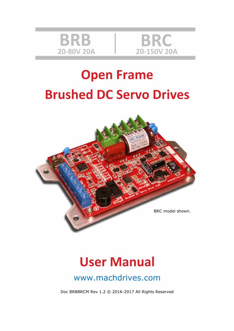
Product Identifier
BR B n
Motor Type: Series: Version Number
BR = Brushed DC B= B Series Optional number
BL = Brushless DC C= C Series
BX = Brush and Brushless DC
AC = AC
ST = Stepper
BRB, BRC Series User Manual Machdrives Open Frame Brushed DC Servo Drives
BRBBRCM V1.2 3 www.machdrives.com
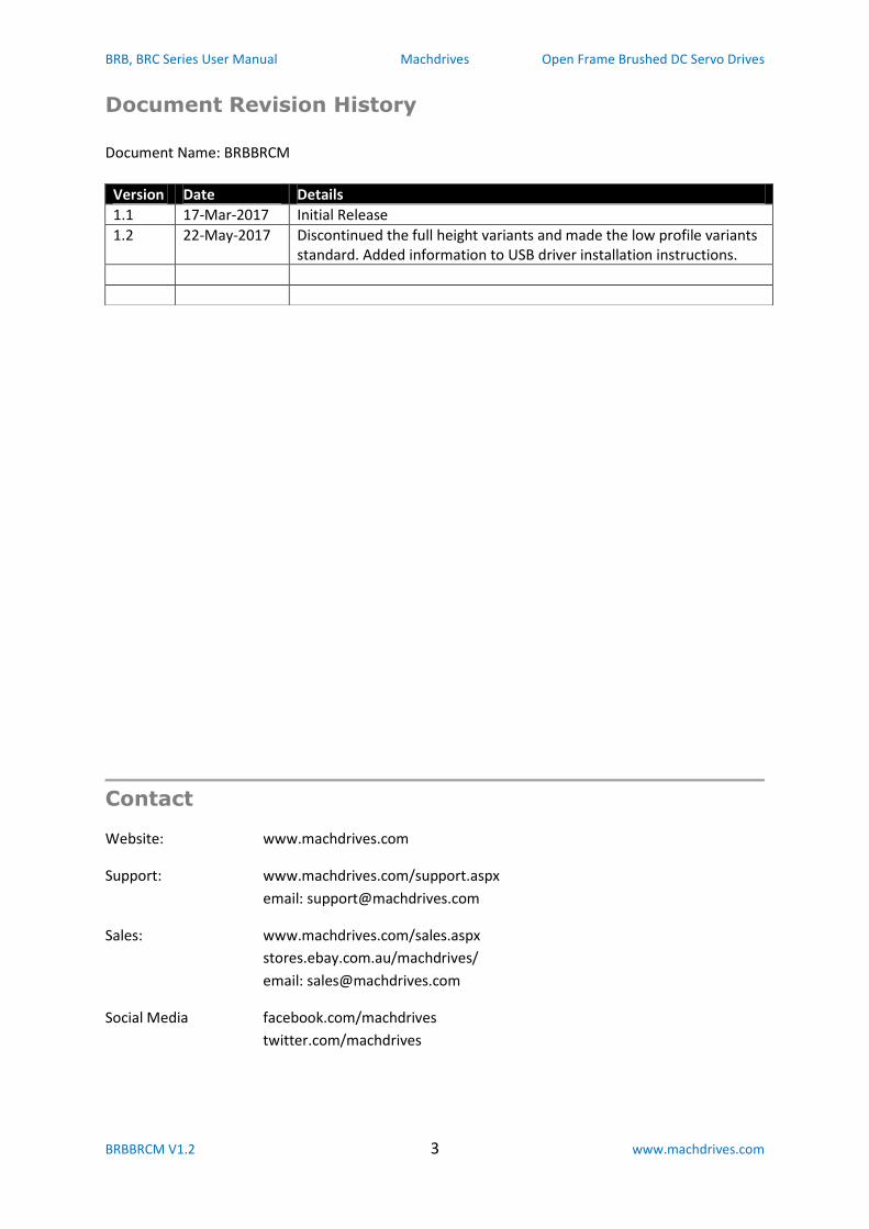
Document Revision History
Document Name: BRBBRCM
Contact
Website: www.machdrives.com
Support: www.machdrives.com/support.aspx
email: [email protected]
Sales: www.machdrives.com/sales.aspx
stores.ebay.com.au/machdrives/
email: [email protected]
Social Media facebook.com/machdrives
twitter.com/machdrives
Version Date Details
1.1 17-Mar-2017 Initial Release
1.2 22-May-2017 Discontinued the full height variants and made the low profile variants standard. Added information to USB driver installation instructions.
BRB, BRC Series User Manual Machdrives Open Frame Brushed DC Servo Drives
BRBBRCM V1.2 4 www.machdrives.com
CONTENTS
1.0 SAFETY .............................................................................................................................................................. 6
1.1 Warnings ...................................................................................................................................................... 6
1.2 Cautions ........................................................................................................................................................ 7
1.3 Hot Surfaces ................................................................................................................................................. 7
1.4 Standards and Conformance ........................................................................................................................ 8
1.5 Warranty ...................................................................................................................................................... 8
2.0 INTRODUCTION................................................................................................................................................. 9
2.1 Drive Description .......................................................................................................................................... 9
2.2 Drive Features .............................................................................................................................................. 9
2.2.1 Advanced Control Algorithm ................................................................................................................. 9
2.2.2 Easy Setup and Operation ................................................................................................................... 10
2.2.3 Advanced Power Stage ....................................................................................................................... 10
2.3 Drive Architecture ...................................................................................................................................... 11
2.4 Drive Layout ............................................................................................................................................... 11
2.5 Drive Models and Variants ......................................................................................................................... 12
3.0 INSTALLATION ................................................................................................................................................. 13
3.1 Unpacking the Drive ................................................................................................................................... 13
3.2 Environmental Requirements .................................................................................................................... 13
3.3 Mounting the Drive .................................................................................................................................... 13
3.4 Connecting the Drive .................................................................................................................................. 15
3.4.1 Earth Connection ................................................................................................................................ 15
3.4.2 USB Connection .................................................................................................................................. 15
3.4.3 +5V Control Supply Connection .......................................................................................................... 15
3.4.4 Encoder Cable Connection .................................................................................................................. 16
3.4.5 Control Interface Connection.............................................................................................................. 16
3.4.6 Power Connection ............................................................................................................................... 18
3.4.7 Motor Connection ............................................................................................................................... 18
3.4.8 Grounding and Earthing ...................................................................................................................... 19
4.0 CONFIGURATION ............................................................................................................................................ 20
BRB, BRC Series User Manual Machdrives Open Frame Brushed DC Servo Drives
BRBBRCM V1.2 5 www.machdrives.com
4.1 Installing the Tuna Software ...................................................................................................................... 20
4.2 Installing the USB drivers ........................................................................................................................... 20
4.3 Activating the Drive .................................................................................................................................... 21
4.4 Step/Dir (Command) Configuration ........................................................................................................... 21
4.5 Encoder Configuration ............................................................................................................................... 22
4.6 Sound and LED Configuration ..................................................................................................................... 22
4.7 Miscellaneous Configuration ...................................................................................................................... 23
5.0 TUNING ........................................................................................................................................................... 24
5.1 PID Parameters ........................................................................................................................................... 24
5.2 Checklist ..................................................................................................................................................... 24
5.3 Tuning the Velocity Loop ............................................................................................................................ 25
5.4 Tuning the Position Loop ............................................................................................................................ 27
5.5 Fine Tuning ................................................................................................................................................. 29
6.0 MONITORING .................................................................................................................................................. 30
7.0 FAULT CODES .................................................................................................................................................. 30
8.0 LED INDICATORS ............................................................................................................................................. 31
9.0 ALARMS AND NOTIFICATIONS ........................................................................................................................ 31
10.0 SPECIFICATIONS ............................................................................................................................................ 32
BRB, BRC Series User Manual Machdrives Open Frame Brushed DC Servo Drives
BRBBRCM V1.2 6 www.machdrives.com
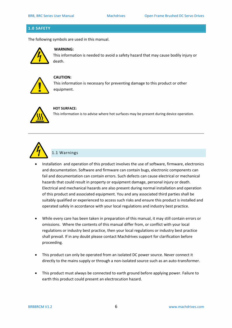
1.0 SAFETY
The following symbols are used in this manual.
WARNING:
This information is needed to avoid a safety hazard that may cause bodily injury or
death.
CAUTION:
This information is necessary for preventing damage to this product or other
equipment.
HOT SURFACE:
This information is to advise where hot surfaces may be present during device operation.
1.1 Warnings
Installation and operation of this product involves the use of software, firmware, electronics
and documentation. Software and firmware can contain bugs, electronic components can
fail and documentation can contain errors. Such defects can cause electrical or mechanical
hazards that could result in property or equipment damage, personal injury or death.
Electrical and mechanical hazards are also present during normal installation and operation
of this product and associated equipment. You and any associated third parties shall be
suitably qualified or experienced to access such risks and ensure this product is installed and
operated safely in accordance with your local regulations and industry best practice.
While every care has been taken in preparation of this manual, it may still contain errors or
omissions. Where the contents of this manual differ from, or conflict with your local
regulations or industry best practice, then your local regulations or industry best practice
shall prevail. If in any doubt please contact Machdrives support for clarification before
proceeding.
This product can only be operated from an isolated DC power source. Never connect it
directly to the mains supply or through a non-isolated source such as an auto-transformer.
This product must always be connected to earth ground before applying power. Failure to
earth this product could present an electrocution hazard.
BRB, BRC Series User Manual Machdrives Open Frame Brushed DC Servo Drives
BRBBRCM V1.2 7 www.machdrives.com
Always ensure motor power is removed from this device by a mechanical or
electromechanical means before placing any body parts in the path of connected machinery.
Never solely rely on electronics or firmware for safety.
Never touch power circuitry or connect/disconnect power or motor connections while
power is applied.
Power cables can carry high voltage even when the motor is stationary. Remove power
before touching conductors.
After removing power wait at least 5 minutes for any stored charge to be dissipated before
touching. If in any doubt confirm safe voltage levels with a meter before proceeding.
1.2 Cautions
The DC power source applied to this product must never exceed the specified maximums.
Allow suitable margins for supply increases during deceleration and braking. Exceeding
maximums can damage the product and void warranty.
Never reverse the polarity of the DC power source. Reversing the power source can damage
the product and void warranty.
The power source must be able to supply the expected maximum current. Exceeding the
capacity of switch mode power sources can result in them "hiccupping", causing the drive to
reset .
The control ground, power ground and earth are all electrically isolated from each other in
the drive. Read and understand section 3.4.9 on "Grounding and Earthing" to avoid ground
loops or damage to connected equipment.
1.3 Hot Surfaces
This product may contain hot surfaces. Exercise care when touching during or after
operation. If elevated temperatures are present, additional cooling such as forced air
circulation may be required.
BRB, BRC Series User Manual Machdrives Open Frame Brushed DC Servo Drives
BRBBRCM V1.2 8 www.machdrives.com
1.4 Standards and Conformance
This product has been designed and constructed to comply with IEC/EN 61800-5-1 as defined below.
This product is classified as an industrial Basic Drive Module (BDM) and sale and installation
is restricted to machine builders and other suitably qualified or experienced persons. This is
not a consumer product.
Protective Class I - Must be installed in a suitable protective earthed metal cabinet.
Over voltage category II - Must be connected to an isolated DC power supply.
Operation in pollution degree 1 or 2 environment only.
Altitude < 2000m.
The machine builder is responsible for designing the system with suitable safety devices and
disconnects.
The machine builder is responsible for ensuring the complete system and all auxiliary
equipment, cabling and motors comply with appropriate local electrical safety regulations
and EMI requirements.
The machine builder shall be suitably qualified or experienced in assessing EMI requirements
to install appropriate EMI filtering if deemed necessary to ensure compliance.
1.5 Warranty
This product is warranted to be free of material defects and workmanship and conform to the published specifications. This product is warranted for a period of 12 months from the time of installation, or 18 months from time of shipment, whichever comes first. Products replaced under warranty are covered under the original warranty period. Physical damage or operation of the product outside of the published specifications is not covered by warranty. All warranty claims must obtain a Return Material Authorization (RMA) number before returning the product. Defective products will be repaired or replaced at the manufacturer's sole discretion. The customer is responsible for the cost of returning the product to the manufacturer. The manufacturer is responsible for the cost of returning the product to the customer by standard airmail service. No other warranties, expressed or implied, including a warranty of merchantability and fitness for a particular purpose, extend beyond this warranty.
BRB, BRC Series User Manual Machdrives Open Frame Brushed DC Servo Drives
BRBBRCM V1.2 9 www.machdrives.com
2.0 INTRODUCTION
Thank you for choosing Machdrives for your new project. We want your experience to be a positive
one, so please contact support if you have any questions about this product or its use.
This user manual describes the Machdrives BRB and BRC series servo drives and their commissioning
as part of a CNC machine or similar system. Please read all sections carefully to ensure the best
performance of your drive and your system as a whole.
2.1 Drive Description
Machdrives BRB and BRC series servo drives are designed for use with brushed DC servo motors and
step/direction CNC control software such as Mach3. These drives are open frame, giving excellent
value for money and are designed to be installed in an enclosed metal control cabinet.
Both models are identical except for the input voltage range, with the BRB requiring 20-80VDC and
the BRC requiring 20-150VDC. Standard height and a low profile variants are also available on both
models. See section 2.5 for details.
The drives must be powered with an isolated DC power supply to drive the motor, and a small 5V DC
isolated supply for the control circuitry and encoders.
The drive is configured and tuned using Machdrives Tuna software via USB. This Windows based
software can be downloaded for free from machdrives.com/tuna.aspx
2.2 Drive Features
2.2.1 Advanced Control Algorithm
Supports modified PI-D (PIV) algorithm.
Dedicated 32 bit ARM control board CPU with double precision floating point
motion calculations.
Command velocity improvement with glitch filter, sliding filter and noise filter.
Frequency and 1/T command velocity estimation with automatic transition.
Velocity and acceleration feed forward with time shifting.
Stiction (static friction) and reversal compensation.
Supports all combinations of metric and imperial hardware. Automatic calculation
of electronic gearing and step multiplying with no loss of precision.
Abnormal condition detection like saturation, following error and encoder fault.
BRB, BRC Series User Manual Machdrives Open Frame Brushed DC Servo Drives
BRBBRCM V1.2 10 www.machdrives.com
2.2.2 Easy Setup and Operation
Standard step and direction input supports popular CNC programs like Mach3.
All PC interface signals are isolated from power circuitry.
Easy drive commissioning with free Machdrives Tuna software for Windows via USB.
14 LED indicators show all I/O states without multimeters or oscilloscopes. Signals
too fast or short to be seen are "shifted" into the visible range.
In-built waveform generator creates tuning waveforms such as trapezoid and S-
profile.
Easy parameter configuration. Values can be keyed in directly or + and - keys can be
used for live "nudging" of tuning values.
Six channel scope with pan and zoom for easy waveform analysis.
Digital readouts on command and motor positions.
Real time statistical motor position error analysis and charting over multiple time
intervals.
Automatic saving of values.
Ability to assign drive axis names and connect multiple drives at the same time.
2.2.3 Advanced Power Stage
Under and over voltage monitoring and alarms. User adjustable current limit from 5
to 20A. Current limiting alert.
High efficiency MOSFET bridge. Typical applications do not require a dedicated
heatsink. Steel control cabinet wall mounting is normally sufficient.
Dedicated 32 bit ARM CPU for power stage.
Silent operation. No singing or dithering.
Optional power saving mode significantly reduces drive and motor losses with no
effect on performance.
Output short circuit protection.
Intelligent overload protection.
Snubber circuit across motor output with additional snubbers on power rail.
Thermal monitoring of heatsink with audible warning and shutdown.
High efficiency DC-DC converter supplies power stage with negligible losses and
spread-spectrum frequency for reduced EMI.
Power stage is isolated from control circuitry and earth.
BRB, BRC Series User Manual Machdrives Open Frame Brushed DC Servo Drives
BRBBRCM V1.2 11 www.machdrives.com
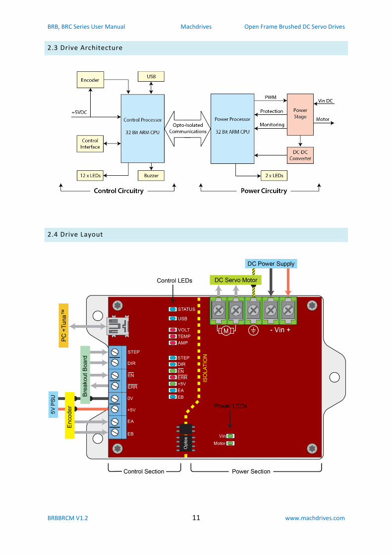
2.3 Drive Architecture
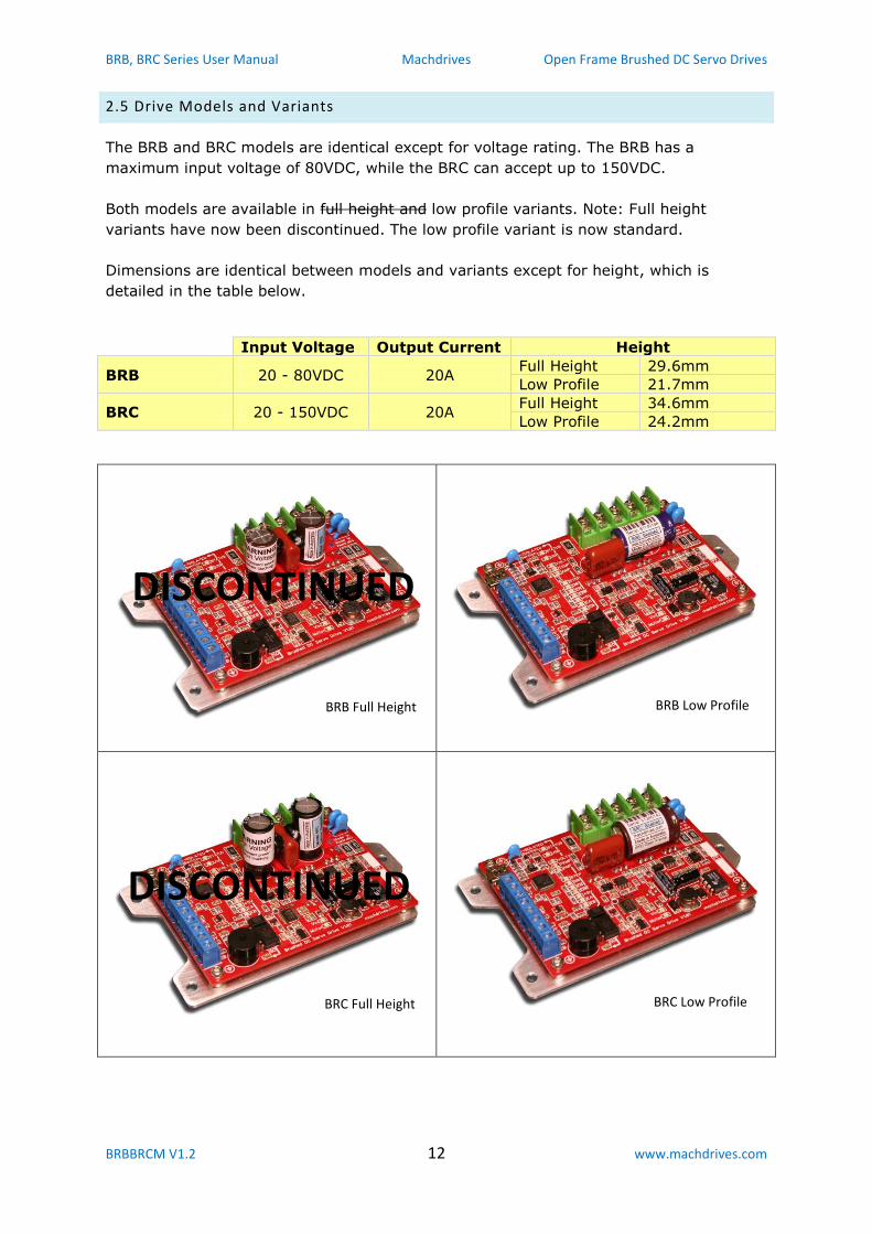
2.4 Drive Layout
BRB, BRC Series User Manual Machdrives Open Frame Brushed DC Servo Drives
BRBBRCM V1.2 12 www.machdrives.com
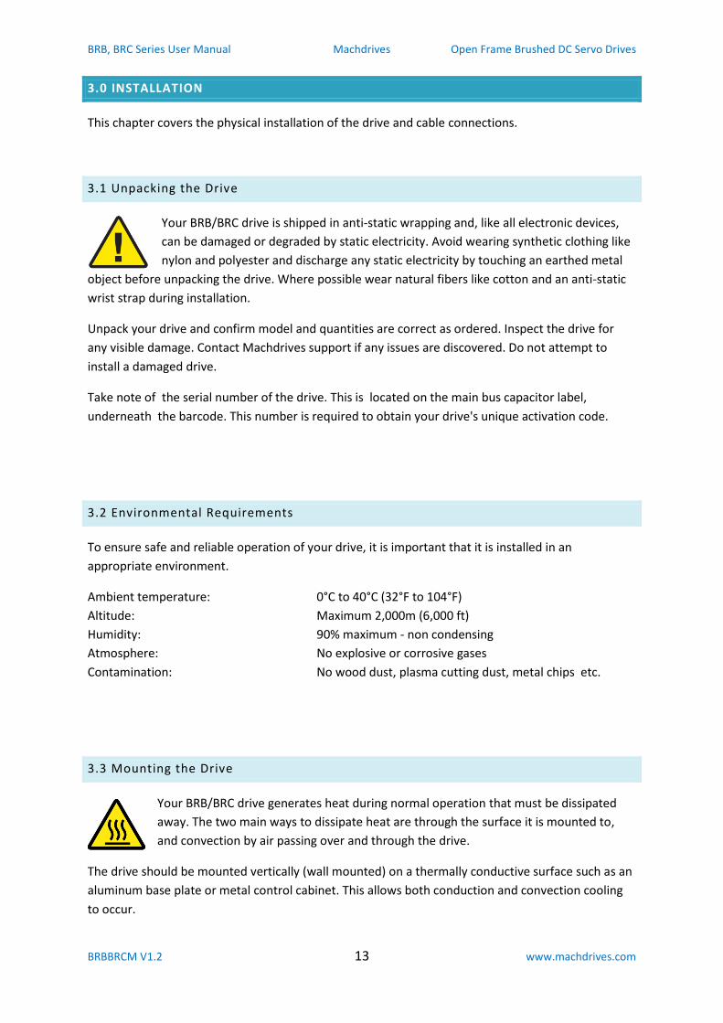
2.5 Drive Models and Variants
The BRB and BRC models are identical except for voltage rating. The BRB has a
maximum input voltage of 80VDC, while the BRC can accept up to 150VDC.
Both models are available in full height and low profile variants. Note: Full height
variants have now been discontinued. The low profile variant is now standard.
Dimensions are identical between models and variants except for height, which is
detailed in the table below.
Input Voltage Output Current Height
BRB 20 - 80VDC 20A Full Height 29.6mm
Low Profile 21.7mm
BRC 20 - 150VDC 20A Full Height 34.6mm
Low Profile 24.2mm
BRB Low Profile BRB Full Height
BRC Full Height BRC Low Profile
DISCONTINUED
DISCONTINUED
BRB, BRC Series User Manual Machdrives Open Frame Brushed DC Servo Drives
BRBBRCM V1.2 13 www.machdrives.com
3.0 INSTALLATION
This chapter covers the physical installation of the drive and cable connections.
3.1 Unpacking the Drive
Your BRB/BRC drive is shipped in anti-static wrapping and, like all electronic devices,
can be damaged or degraded by static electricity. Avoid wearing synthetic clothing like
nylon and polyester and discharge any static electricity by touching an earthed metal
object before unpacking the drive. Where possible wear natural fibers like cotton and an anti-static
wrist strap during installation.
Unpack your drive and confirm model and quantities are correct as ordered. Inspect the drive for
any visible damage. Contact Machdrives support if any issues are discovered. Do not attempt to
install a damaged drive.
Take note of the serial number of the drive. This is located on the main bus capacitor label,
underneath the barcode. This number is required to obtain your drive's unique activation code.
3.2 Environmental Requirements
To ensure safe and reliable operation of your drive, it is important that it is installed in an
appropriate environment.
Ambient temperature: 0°C to 40°C (32°F to 104°F)
Altitude: Maximum 2,000m (6,000 ft)
Humidity: 90% maximum - non condensing
Atmosphere: No explosive or corrosive gases
Contamination: No wood dust, plasma cutting dust, metal chips etc.
3.3 Mounting the Drive
Your BRB/BRC drive generates heat during normal operation that must be dissipated
away. The two main ways to dissipate heat are through the surface it is mounted to,
and convection by air passing over and through the drive.
The drive should be mounted vertically (wall mounted) on a thermally conductive surface such as an
aluminum base plate or metal control cabinet. This allows both conduction and convection cooling
to occur.
BRB, BRC Series User Manual Machdrives Open Frame Brushed DC Servo Drives
BRBBRCM V1.2 14 www.machdrives.com
The drive may also be mounted horizontally on a thermally conductive surface if adequate air flows
are available over the drive.
The drive should not be mounted on a poor thermal conductor such as Bakelite or fiber board.
If the drive is installed in an enclosed space, make sure heat does not build up, and take additional
steps as required, such as forced air cooling.
For typical applications such as a small CNC mill, mounting on a steel control cabinet wall will
normally provide sufficient heat dissipation. For more demanding applications a small heatsink or
aluminium base plate may be required.
Remember the operating life of all electronic devices is adversely effected by temperature. Aim for
the best cooling practical for your installation to maximize operational life.
Note: Your local electrical regulations may also impose requirements that affect your installation,
such as mounting the drive in a locked and earthed metal cabinet.
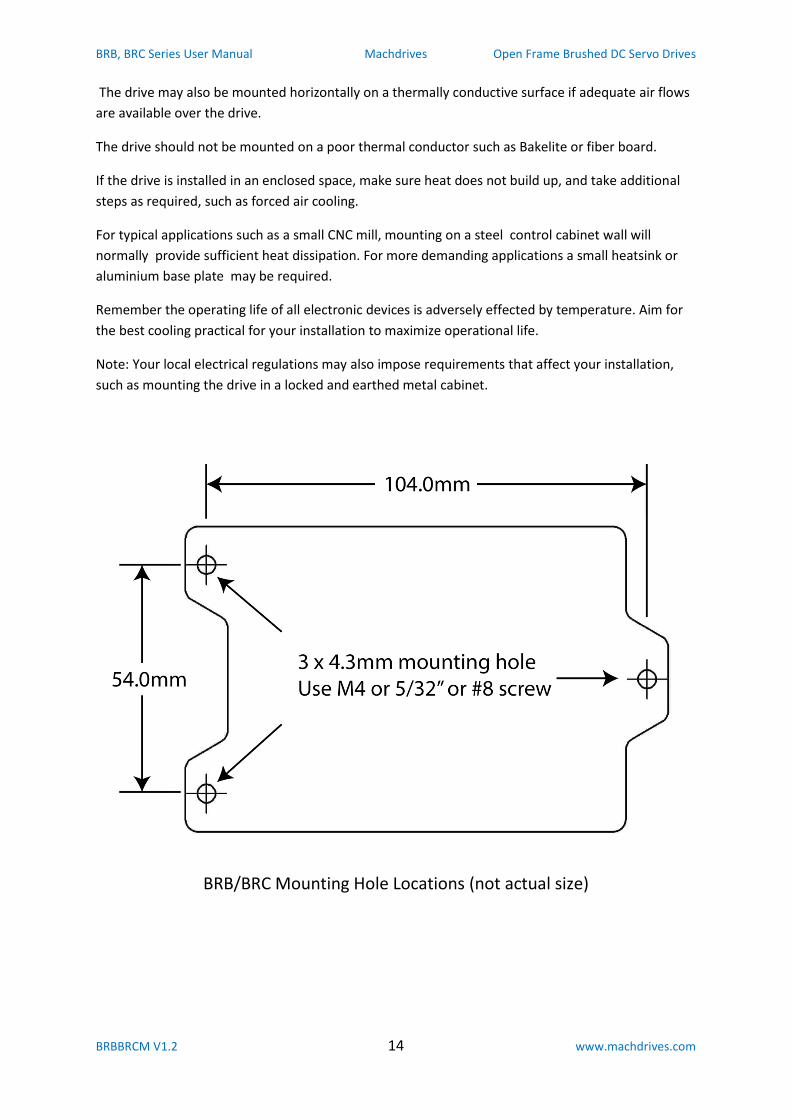
BRB/BRC Mounting Hole Locations (not actual size)
BRB, BRC Series User Manual Machdrives Open Frame Brushed DC Servo Drives
BRBBRCM V1.2 15 www.machdrives.com
3.4 Connecting the Drive
3.4.1 Earth Connection
IMPORTANT: This drive must NOT be operated without an earth connection. It
is recommended that the earth terminal is connected to a copper earth bar
with a short braided strap no longer than 75mm (3 in).
3.4.2 USB Connection
A mini-B USB cable is required to use the Machdrives Tuna application. Make sure the PC
has internet connection before plugging in the drive for the first time. This will enable it to
find and install the correct USB driver automatically.
It is important that a good quality shielded USB cable is used with the shield
connected to the metal shells at both ends as required by the USB standard.
During testing different low cost "shielded" USB cables were purchased online
and most were found to be faulty with the shield not connected.
A properly constructed cable should never drop the connection between the drive and the
Tuna software. If in doubt check both end shells for continuity with a meter, then strip the
sleeve from a small section in the middle of the cable and check the braided shield to end
shell for continuity as well.
3.4.3 +5V Control Supply Connection
A small isolated +5VDC power supply is required to power the drive control circuitry and the
encoder. The same PSU can power multiple drives, with a 5V 1A unit being ideal for a three
drive system.
Connect the power supply positive to the +5V terminal and the negative to the 0V terminal.
Do not use the PC internal 5V supply as this can cause return currents to flow in any data
cables connected to the PC.
Do not use a supply sharing a common ground with the motor power circuitry, as this will
connect the control ground and power ground together.
Route the 5VDC cable well away from motor cables and twist together or use shielded cable for maximum noise immunity. If using a shielded cable, earth the shield at both ends.
BRB, BRC Series User Manual Machdrives Open Frame Brushed DC Servo Drives
BRBBRCM V1.2 16 www.machdrives.com
3.4.4 Encoder Cable Connection
Your BRB/BRC drive will work with all commonly available types of encoders, including single
ended TTL, differential line drive, and open collector output.
Connect the +5V and 0V terminals to your encoder's respective power connections. Connect
the encoder A and B outputs to the EA and EB input terminals respectively. If using a
differential encoder, connect the A+ and B+ outputs and leave the A- and B- outputs
unconnected.
Open collector output encoders can be directly connected as the drive already contains 2K7
pull-up resistors on both the EA and EB inputs.
If using HEDS encoders, be sure to wire a 0.1uF decoupling capacitor across the +5V and 0V
pins of the encoder as close to the encoder body as possible.
Use good quality shielded cable where possible and connect the shield to a convenient earth
point at the drive end. Leave the shield at the encoder end unconnected and insulate with
heatshrink to prevent accidental shorts. Route the wires well away from motor cables.
The +5V supply must be present before the encoder can operate. Operation can be checked
by slowly turning the shaft and observing the EA and EB LEDs.
Digital filtering on the encoder inputs can be configured through the Tuna application. The
default values work well to eliminate noise in most situations.
3.4.5 Control Interface Connection
The Control Interface allows your PC to control the drive using Step/Direction CNC control
software such as Mach3 or similar. The drive receives STEP, DIR (direction) and (enable)
signals from the PC and sends back the (error) signal.
Signals with lines above the name such as are active low. This means the condition has
occurred when the signal goes low (in this case an error condition). Signals without lines are
active high.
All Control Interface signals are isolated from the drive power circuitry, so additional opto-
isolation is not required. These signals are normally connected to the PC via a breakout
board such as the Machdrives 4 axis breakout boards.
Use shielded cable where possible and connect the shield to a convenient earth point near
the drive. Leave the shield at the breakout board end unconnected, and insulate with
heatshrink to prevent accidental shorts. Route the wires well away from motor cables.
STEP: A step occurs on the low to high transition of this signal. Software like Mach3 then
holds the signal high for 1-5uS before returning it low again, ready for the next step.
BRB, BRC Series User Manual Machdrives Open Frame Brushed DC Servo Drives
BRBBRCM V1.2 17 www.machdrives.com
DIR: A low level means steps move the axis in the positive direction, and a high level in the
negative direction. The direction signal must not change state at the same time as the step
transition occurs or the step direction will be indeterminate.
: This enable input is active low, and all drives should have this line connected together. A
low level will enable the drives if no alarm conditions are present, otherwise the output
will be activated and the enable request will be ignored.
: This error output is active low, and all drives should have this line connected together.
The drive will pull this line low if an alarm condition occurs. While this is an output, drives
can also detect if it is pulled low by another drive, and will stop and raise an external error
alarm.
0V: This is the control ground, and all drives should have this line connected together. This
terminal is also connected to the negative of the 5V control power supply and the 0V pin of
the encoder.
Do not connect the control ground to the power ground used by the motors
as this will bypass the safety isolation and may pose an electrocution hazard
or damage connected equipment.
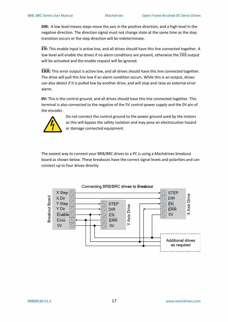
The easiest way to connect your BRB/BRC drives to a PC is using a Machdrives breakout
board as shown below. These breakouts have the correct signal levels and polarities and can
connect up to four drives directly.
BRB, BRC Series User Manual Machdrives Open Frame Brushed DC Servo Drives
BRBBRCM V1.2 18 www.machdrives.com
3.4.6 Power Connection
Power supply voltages can be hazardous. Read the safety section at the
beginning of this manual before proceeding.
Your BRB/BRC drive requires an isolated DC power supply (PSU) of at least 20VDC. Supply
voltage is normally determined by the rating of the motors. Choose a voltage that is the
same or slightly higher than the motor's rated voltage. Allow enough margin for the voltage
to rise under motor deceleration without exceeding the maximum voltage. The PSU should
be able to supply the full 20A peak per drive, or maximum current limit as configured in the
Tuna application.
The supply can be a switching or linear type. If using a switching type, make sure it can
handle the current required without tripping out or "hiccupping". If using a linear type, make
sure the ripple voltage is sufficiently low at maximum current. To reduce ripple, increase the
power supply capacitance. High ripple voltage will result in increased drive bus capacitor
temperature and reduced life expectancy.
Drives may use individual power supplies or share the same larger power supply. Connect
each drive directly to the power supply. Do not daisy chain drives together. Use heavy gauge
wire and twist positive and negative together, or use shielded power cable and earth the
shield at both ends.
Keep the power cables between the drive and the power supply as short as possible. If this is
not possible then additional capacitance will need to be placed near the drive to counteract
the lead inductance.
Connect the wires to the barrier strip connector using spade terminal connectors, and route
all power cables well away from control cables. Double check that the power supply
positive and negative are the correct way around, as incorrect polarity can destroy the
drive.
Place any power on/off switch on the AC side of the power supply. Do not place a switch on
the DC bus supply side as opening it while the drive is running could damage the drive.
3.4.7 Motor Connection
Motor voltages can be hazardous. Read the safety section at the beginning of
this manual before proceeding.
While your BRB/BRC drive incorporates EMI reduction features, the motor outputs can still
be a source of interference if not properly connected.
Always connect the drive to the motor using shielded motor cable and connect the shield to
earth at both ends.
BRB, BRC Series User Manual Machdrives Open Frame Brushed DC Servo Drives
BRBBRCM V1.2 19 www.machdrives.com
Use a metal saddle to clamp the shield around 360 degrees to an earth plane. Avoid long
wire pigtails between the shield and earth as lead inductance reduces the shields
effectiveness.
Connect the wires to the barrier strip connector using spade terminal connectors, and route
all motor cables well away from control cables.
If required, common mode noise can be further reduced by passing the two motor wires
together several times through a toroidal ferrite core, before screwing on to the barrier strip
connector. Do not pass the earth wire or shield through the core and do not use a powered
iron toroid.
3.4.8 Grounding and Earthing
Your BRB/BRC drive has three electrically isolated circuits for safety, to eliminate ground
loops and to provide a high level of noise immunity. There is no connection between these
sections inside the drive.
The "Power Ground" is the Vin negative terminal on the barrier strip connector. This
is the ground for the power stage that controls the motor, and can contain motor
switching noise.
The "Control Ground" is the 0V terminal on the Control Interface. This is a quiet
ground and is only used for control signals.
The "Earth" is the center terminal on the barrier strip connector. This is connected
to the drive's metal base plate for safety and EMI shielding.
Do not connect the power ground, control ground or earth together, or share any power
supplies or other circuitry between them.
After your system is completely wired up, turn off all power then verify with a meter that
the two grounds and earth are all isolated from each other. Note: It is normal and
acceptable for your PC to connect the control ground and earth together inside the
computer power supply. Unplug any data cables connecting the PC to the system for the
purpose of this test. If any connection is found, isolate the cause and rectify if before
operating the system.
BRB, BRC Series User Manual Machdrives Open Frame Brushed DC Servo Drives
BRBBRCM V1.2 20 www.machdrives.com
4.0 CONFIGURATION
Configuring your drive is done through the Machdrives Tuna application for Windows. The drive is
connected to the PC with a Mini-B USB cable. It is possible to configure the parameters and activate
the drive with only the USB cable connected, no other power is required. However other circuitry
such as the encoder will not function until the 5VDC supply is connected.
4.1 Installing the Tuna Software
The Tuna application for Windows can be downloaded from https://machdrives.com/tuna.aspx
There is a choice of two different downloads. They are the same program but use different versions
of the .Net framework.
Tuna for Windows XP. This uses the .Net 2.0 framework for older PC's
Tuna for Windows 7, 8.x, 10. This uses the .Net 4.0 framework for newer PC's
Install the software. On newer versions of Windows you need to right click the .exe and select "Run
as administrator". You will need to read and accept the EULA before installing the software.
4.2 Installing the USB drivers
Your drive appears as a Virtual COM Port to Windows and needs a VCP driver to communicate.
Make sure the PC has internet connection before connecting the USB cable for the first time. The
drive does not need power or any other cables connected. The PC will automatically download and
install the correct driver. This may take a few minutes.
If there is no internet connection the first time the drive is plugged in, Windows will not install the
drivers on subsequent connections. You will then need to open Device Manager/Ports and find the
USB Serial Device and uninstall it before trying again. Note: the device will only be listed if the USB
cable is connected to the drive.
Whether the Tuna application is installed or open has no effect on the driver installation.
If the drivers do not download automatically check your Windows setting under "Devices and
Printers", right click the icon with your computer name and select "Device Installation Settings".
Make sure driver download is set to Automatic.
If you are installing the software on a PC where internet connection is not available then please
contact us on [email protected] for a driver install package.
BRB, BRC Series User Manual Machdrives Open Frame Brushed DC Servo Drives
BRBBRCM V1.2 21 www.machdrives.com
4.3 Activating the Drive
Your drive requires a one-time activation before it is fully functional. Activation ensures that only
the correct person receives and commissions the drive, and that you have received a genuine
Machdrives product.
To activate your drive send the serial numbers to [email protected] or via eBay order
messages, and request the activation codes.
You will receive back a 24 character code in the format: DGLH-LXMI-LWXU-MFEI-HIHG-FZXD
Every code is unique and will only work in the drive with the supplied serial number.
Open the Tuna application and plug the USB cable into the drive. An orange key will appear on the
title bar. Click the key and paste the code in the dialog box exactly as supplied, then click OK. The key
will disappear and you will receive a confirmation that the drive has been activated. If the code is
entered incorrectly three times, the Tuna application will need to be restarted before it can be
attempted again.
You should receive the activation code within one business day of requesting it. While you are
waiting you can still install and configure the drive. You can also tune it by setting the command
source to "Wave Generator". This uses the internal motion profile generator as the command
source. The drive cannot however be commanded from the Step/Direction interface until it has been
activated.
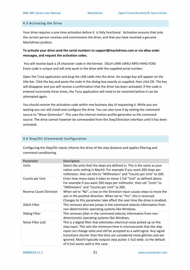
4.4 Step/Dir (Command) Configuration
Configuring the Step/Dir Inputs informs the drive of the step distance and applies filtering and
command conditioning.
Parameter Description
Units Select the units that the steps are defined in. This is the same as your native units setting in Mach3. For example if you want 200 steps per millimeter, then set this to "Millimeters" and "Counts per Unit" to 200.
Counts per Unit Enter how many steps it takes to move 1 full "Unit" as defined above. For example if you want 200 steps per millimeter, then set "Units" to "Millimeters" and "Counts per Unit" to 200.
Reverse Count Direction When set to "No", a low on the Direction input causes steps to move the axis in the positive direction. When set to "Yes", this is reversed. Changes to this parameter take effect the next time the drive is enabled.
Glitch Filter This removes discrete jumps in the command velocity information from non-deterministic operating systems like Windows.
Sliding Filter This removes jitter in the command velocity information from non-deterministic operating systems like Windows.
Noise Filter (uS) This is a digital filter that eliminates electrical noise picked up on the step input. This sets the minimum time in microseconds that the step input can change state and still be accepted as a valid signal. Any signal transitions shorter than this time are considered noise glitches and are ignored. Mach3 typically outputs step pulses 1-5uS wide, so the default of 0.5uS works well in this case.
BRB, BRC Series User Manual Machdrives Open Frame Brushed DC Servo Drives
BRBBRCM V1.2 22 www.machdrives.com
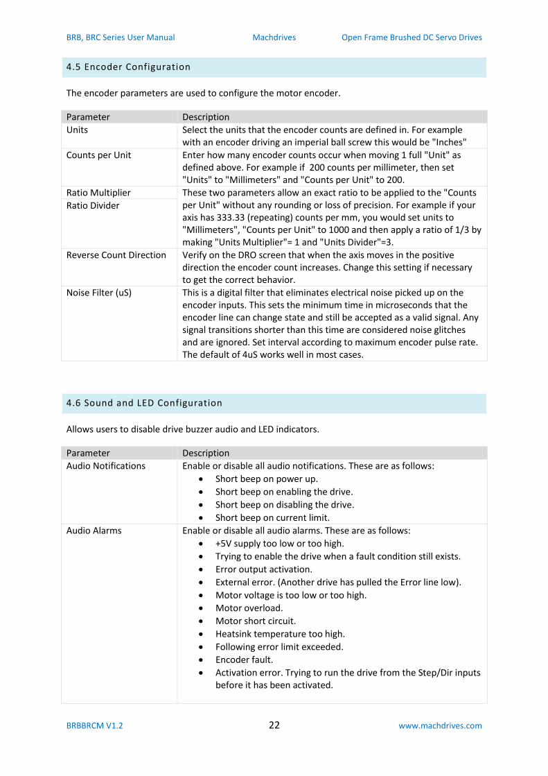
4.5 Encoder Configuration
The encoder parameters are used to configure the motor encoder.
Parameter Description
Units Select the units that the encoder counts are defined in. For example with an encoder driving an imperial ball screw this would be "Inches"
Counts per Unit Enter how many encoder counts occur when moving 1 full "Unit" as defined above. For example if 200 counts per millimeter, then set "Units" to "Millimeters" and "Counts per Unit" to 200.
Ratio Multiplier These two parameters allow an exact ratio to be applied to the "Counts per Unit" without any rounding or loss of precision. For example if your axis has 333.33 (repeating) counts per mm, you would set units to "Millimeters", "Counts per Unit" to 1000 and then apply a ratio of 1/3 by making "Units Multiplier"= 1 and "Units Divider"=3.
Ratio Divider
Reverse Count Direction Verify on the DRO screen that when the axis moves in the positive direction the encoder count increases. Change this setting if necessary to get the correct behavior.
Noise Filter (uS) This is a digital filter that eliminates electrical noise picked up on the encoder inputs. This sets the minimum time in microseconds that the encoder line can change state and still be accepted as a valid signal. Any signal transitions shorter than this time are considered noise glitches and are ignored. Set interval according to maximum encoder pulse rate. The default of 4uS works well in most cases.
4.6 Sound and LED Configuration
Allows users to disable drive buzzer audio and LED indicators.
Parameter Description
Audio Notifications Enable or disable all audio notifications. These are as follows:
Short beep on power up.
Short beep on enabling the drive.
Short beep on disabling the drive.
Short beep on current limit.
Audio Alarms Enable or disable all audio alarms. These are as follows:
+5V supply too low or too high.
Trying to enable the drive when a fault condition still exists.
Error output activation.
External error. (Another drive has pulled the Error line low).
Motor voltage is too low or too high.
Motor overload.
Motor short circuit.
Heatsink temperature too high.
Following error limit exceeded.
Encoder fault.
Activation error. Trying to run the drive from the Step/Dir inputs before it has been activated.
BRB, BRC Series User Manual Machdrives Open Frame Brushed DC Servo Drives
BRBBRCM V1.2 23 www.machdrives.com
LEDs Enable:
All All LED indicators are operational.
Power and Status Only Only power and status LED indicators are operational. All others are off.
LED Brightness Sets the brightness of the 12 control LEDs. Adjustable from 25 to 100%.
4.7 Miscellaneous Configuration
Miscellaneous drive settings.
Parameter Description
Drive Axis Assign an axis letter to the drive. This replaces the COM port number in the Tuna application title bar and Windows task bar. This helps identify which drive is connected when configuring multiple drives.
Current Limit Sets the maximum current the drive will deliver to the motor before current limiting. Normally left at maximum setting of 20A.
Temperature Units Temperatures on the monitoring tab can be displayed in either Celsius or Fahrenheit.
Power Saving: Determines how the power stage behaves when the drive is enabled yet the motor is stationary. In most applications, power saving will reduce drive and motor heating. This is also useful where the machine finishes operations while unattended (lights-out machining).
Disabled No power saving. The power stage remains on when motor is stationary.
Enabled Enables relaxed power saving. This allows the motor shaft to relax due to ballscrew torsion or belt stretch when power is removed. The drive will still restart instantly when a command is received or the motor shaft moves off the relaxed position.
BRB, BRC Series User Manual Machdrives Open Frame Brushed DC Servo Drives
BRBBRCM V1.2 24 www.machdrives.com
5.0 TUNING
Tuning your drive is done through the Machdrives Tuna application for Windows which can be
downloaded from https://machdrives.com/tuna.aspx.
The objective of tuning a single encoder system is to get the motor shaft to follow the commanded
position as accurately as possible. The motor should be tuned while connected to the machine as the
drivetrain characteristics will affect the tuning parameters.
5.1 PID Parameters
The following parameters are used for tuning single encoder systems.
Parameter Description
Proportional Gain This is the Proportional gain, the "P" element in PID.
Integral Gain This is the Integral gain, the "I" element in PID.
Differential Gain This is the Differential gain, the "D" element in PID.
Velocity Feedforward The Velocity Feedforward value is used to eliminate position error under constant velocity.
Acceleration Feedforward Acceleration Feedforward is used to eliminate position error under acceleration.
Stiction Compensation Stiction Compensation eliminates errors at the beginning of moves.
5.2 Checklist
For successful tuning the following items must be correct. Check them and correct any deficiencies
before proceeding.
"Step/Dir Input" parameters set correctly on Configuration tab.
"Encoder" parameters set correctly on Configuration tab.
The encoder is checked by manually moving the axis and checking that the DRO value moves
by the correct amount, and in the correct direction.
"Power Saving" is disabled on Configuration tab.
Machine axis is positioned in center of travel.
Set "Following Error" on the Tuning tab to the number of command steps for two
revolutions of the motor. E.g. If step input is set to 200 steps/mm and the axis moves 5mm
for one motor rotation, then set the following error to 200 x 5 x 2 = 2000 steps.
BRB, BRC Series User Manual Machdrives Open Frame Brushed DC Servo Drives
BRBBRCM V1.2 25 www.machdrives.com
5.3 Tuning the Velocity Loop
The velocity loop must be tuned first. The objective is to get the motor velocity to follow the
command velocity as closely as possible with good stability and no overshoot. This loop is tuned with
a square velocity waveform, which exposes any instabilities, making tuning easier.
1. Set all PID parameters on the Tuning tab to Disable or zero (with the exception of "Following
Error").
2. Set the Wave Generator parameters on the Tuning tab as follows:
a. Pulse Polarity: Positive
b. Distance: Number of command steps for one motor revolution. This will be half the
value entered in "Following Error".
c. Velocity: Enter the value that gives half the "Feed Rate" that you will most
commonly use during machining operation.
d. Acceleration Time: Set to zero. This is important as it generates the required square
velocity profile.
e. Pause Time: 250mS
f. Repeat: Yes
3. Set the "Command Source" dropdown under the scope display to "Wave Generator"
WARNING: The following steps will power the motor and result in machine
motion. Make sure all personnel are clear of the machine and a method of shutting
off machine power is available and close to hand if required.
4. Apply motor power to the drive and check the green Vin LED is on.
5. Enable the drive by pulling the Enable pin down to 0V. The drive will give one short beep and
the Enable LED will be on. Check the Motor LED located by the power connector is on. The
power stage is now ready to drive the motor.
6. On the Velocity grid, tick the "Command" and "Motor" traces. Clear all other traces. Only the
Velocity grid should now be showing.
7. Press the Sweep "START" button and set both trace scales to the same value with
waveforms visible.
8. Start increasing the "Proportional Gain" first, then the "Differential Gain", while referring to
the example traces below. Keep adjusting only these two values until a well tuned velocity
loop is obtained.
If the drive faults out and the motor trace moves in the wrong direction, remove motor power and
reverse the motor wires. DO NOT reverse the Vin power wires by mistake.
If the drive starts current limiting during tuning, then stop and reduce the Wave Generator velocity
by half, then start the tuning again.
BRB, BRC Series User Manual Machdrives Open Frame Brushed DC Servo Drives
BRBBRCM V1.2 26 www.machdrives.com
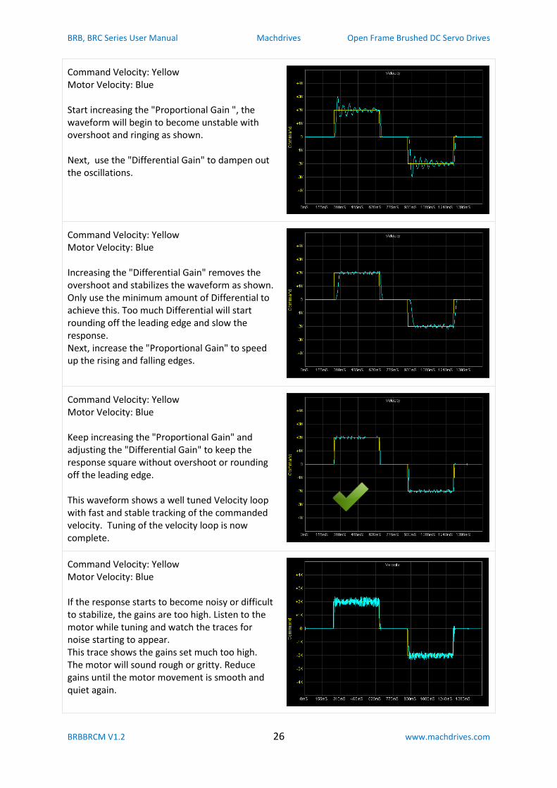
Command Velocity: Yellow Motor Velocity: Blue Start increasing the "Proportional Gain ", the waveform will begin to become unstable with overshoot and ringing as shown. Next, use the "Differential Gain" to dampen out the oscillations.
Command Velocity: Yellow Motor Velocity: Blue Increasing the "Differential Gain" removes the overshoot and stabilizes the waveform as shown. Only use the minimum amount of Differential to achieve this. Too much Differential will start rounding off the leading edge and slow the response. Next, increase the "Proportional Gain" to speed up the rising and falling edges.
Command Velocity: Yellow Motor Velocity: Blue Keep increasing the "Proportional Gain" and adjusting the "Differential Gain" to keep the response square without overshoot or rounding off the leading edge. This waveform shows a well tuned Velocity loop with fast and stable tracking of the commanded velocity. Tuning of the velocity loop is now complete.
Command Velocity: Yellow Motor Velocity: Blue If the response starts to become noisy or difficult to stabilize, the gains are too high. Listen to the motor while tuning and watch the traces for noise starting to appear. This trace shows the gains set much too high. The motor will sound rough or gritty. Reduce gains until the motor movement is smooth and quiet again.
BRB, BRC Series User Manual Machdrives Open Frame Brushed DC Servo Drives
BRBBRCM V1.2 27 www.machdrives.com
5.4 Tuning the Position Loop
The position loop should be tuned with a waveform as close to your typical machining waveform as
possible. This step must follow after tuning the velocity loop.
1. The Wave Generator on the Tuning tab should be configured as follows to give a trapezoid
velocity profile and an S-profile for position.
a. Pulse Polarity: Positive
b. Distance: Number of Command steps for one motor revolution. This will be half the
value entered in "Following Error".
c. Velocity: Adjust this value so the calculated "Feed Rate" shows the value that you
will most commonly use during normal machine operation.
d. Acceleration Time %: Adjust this value so the calculated "Acceleration" value
matches the acceleration set in your CNC controller software. In Mach3 this is on the
"Motor Tuning" screen. If you have not yet determined this value for your machine
then set this parameter to 50%.
e. Pause Time: 250mS
f. Repeat: Yes
2. Set the "Command Source" dropdown under the scope display to "Wave Generator".
WARNING: The following steps will power the motor and result in machine
motion. Make sure all personnel are clear of the machine and a method of shutting
off machine power is available and close to hand if required.
3. Apply motor power to the drive and check the green Vin LED is on.
4. Enable the drive by pulling the Enable pin down to 0V. The drive will give one short beep and
the Enable LED will be on. Check the Motor LED located by the power connector is on. The
power stage is now ready to drive the motor.
5. On the Velocity grid tick the "Command" and "Motor" traces. On the Position grid tick the
"Command", "Motor" and "mError" traces. Clear all other traces. Both grids should now be
showing.
6. Press the Sweep "START" button.
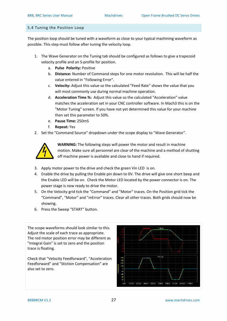
The scope waveforms should look similar to this. Adjust the scale of each trace as appropriate. The red motor position error may be different as "Integral Gain" is set to zero and the position trace is floating. Check that "Velocity Feedforward", "Acceleration Feedforward" and "Stiction Compensation" are also set to zero.
BRB, BRC Series User Manual Machdrives Open Frame Brushed DC Servo Drives
BRBBRCM V1.2 28 www.machdrives.com
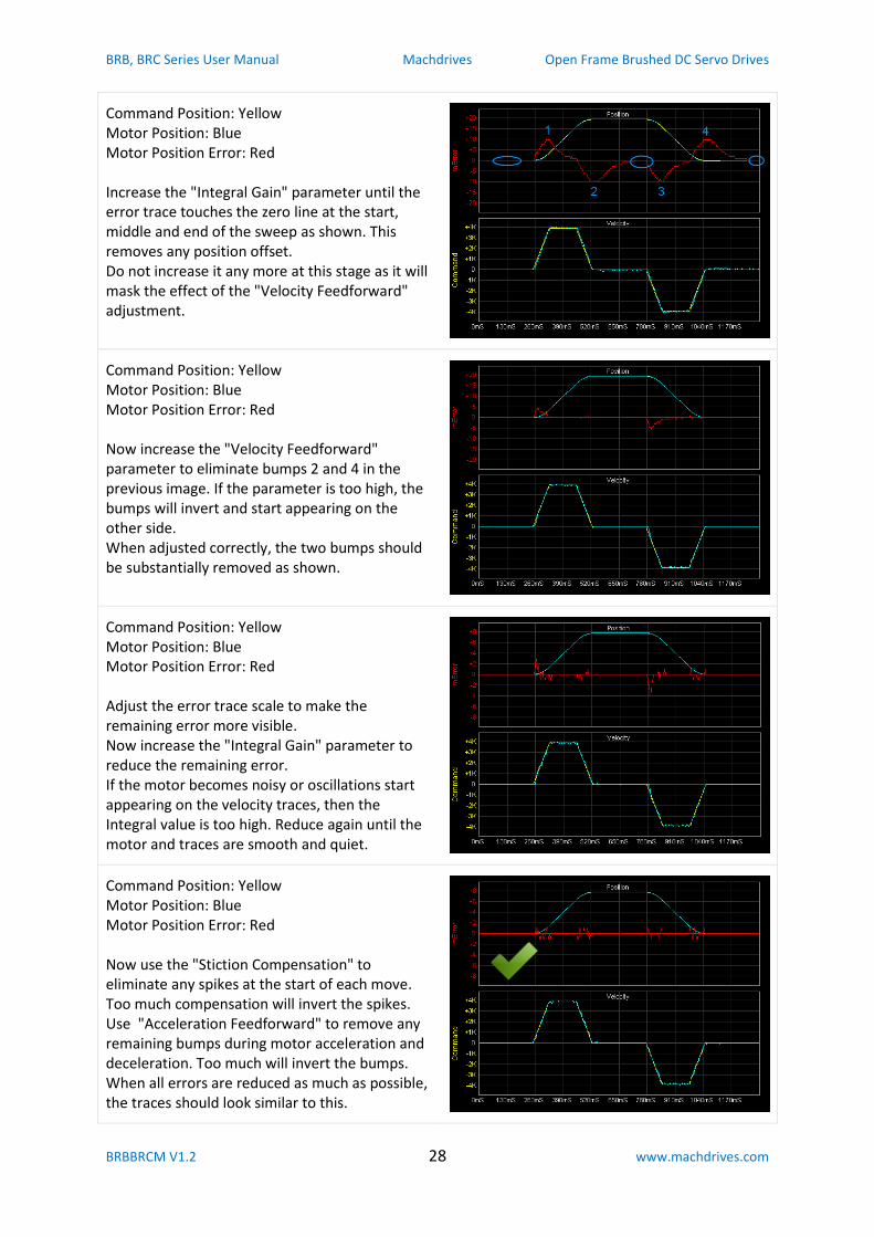
Command Position: Yellow Motor Position: Blue Motor Position Error: Red Increase the "Integral Gain" parameter until the error trace touches the zero line at the start, middle and end of the sweep as shown. This removes any position offset. Do not increase it any more at this stage as it will mask the effect of the "Velocity Feedforward" adjustment.
Command Position: Yellow Motor Position: Blue Motor Position Error: Red Now increase the "Velocity Feedforward" parameter to eliminate bumps 2 and 4 in the previous image. If the parameter is too high, the bumps will invert and start appearing on the other side. When adjusted correctly, the two bumps should be substantially removed as shown.
Command Position: Yellow Motor Position: Blue Motor Position Error: Red Adjust the error trace scale to make the remaining error more visible. Now increase the "Integral Gain" parameter to reduce the remaining error. If the motor becomes noisy or oscillations start appearing on the velocity traces, then the Integral value is too high. Reduce again until the motor and traces are smooth and quiet.
Command Position: Yellow Motor Position: Blue Motor Position Error: Red Now use the "Stiction Compensation" to eliminate any spikes at the start of each move. Too much compensation will invert the spikes. Use "Acceleration Feedforward" to remove any remaining bumps during motor acceleration and deceleration. Too much will invert the bumps. When all errors are reduced as much as possible, the traces should look similar to this.
BRB, BRC Series User Manual Machdrives Open Frame Brushed DC Servo Drives
BRBBRCM V1.2 29 www.machdrives.com
7. After tuning is complete, reduce the "Following Error" to a smaller value e.g. 200, and set
"Power Saving" to "Enabled" if desired.
8. Set the "Command Source" back to "Step/Dir Inputs" so the drive can be commanded from
your CNC Controller software such as Mach3. Both "Glitch" and "Sliding" filters can be
enabled on the Configuration tab.
In this example the Command Steps/Unit was set to 200 steps/mm, so each step is 0.005mm or
0.0002". Much of the move is executed with zero steps error and the bulk of the remainder falls
in the +/- 1 step range (+/-0.005mm).
This tuning example was done on a low end milling machine, and results should be typical for
most users. If there is one secret to obtaining great results it is to use a high resolution optical
encoder on the motor, having 10 (or more) times the command step resolution. This test used a
glass 2,500 line (10,000 count) motor encoder set to 2000 counts/mm.
5.5 Fine Tuning
This is just one way to tune a servo drive. There are many other methods. You can try adjusting the
parameters after tuning to see the effect it has on positioning accuracy. If moves become noisy or
gritty sounding, reduce the gains until moves are smooth and quiet again.
You can also monitor and fine tune the drive while running normal G-Code. Check the "Command
Source" dropdown is set to "Step/Dir Inputs" and the sweep is running.
BRB, BRC Series User Manual Machdrives Open Frame Brushed DC Servo Drives
BRBBRCM V1.2 30 www.machdrives.com
6.0 MONITORING
The Monitoring tab on the Tuna application can be used to check drive health including voltages and
temperatures, as well as recent fault conditions and operating hours.
"Last" values are dynamic and updated continuously.
"Session High" values are from when the drive was last powered up.
"All Time High" values are permanent and cannot be cleared.
"Hours Drive on" records total time the drive has been on, even if the power stage is off.
"Hours Motor on" records total time the power stage has been on and powering the motor. Turning
on power saving will affect this value.
The last five faults are listed with "Fault Last" being the most recent and "Fault Last -4" the oldest.
Existing faults are shuffled back when a new fault occurs and the oldest fault drops off.
7.0 FAULT CODES
Fault codes can be used to identify which fault has just occurred. A fault condition will stop the drive
and sound one long beep. The Status LED will flash a number of times, corresponding to the code as
listed below. The last five faults can also be viewed on the Monitoring tab in the Tuna application.
Code Name Description
1 External Error Another drive has experienced a fault and has pulled the Error line low. This drive will stop and signal an external error condition.
2 +5V Low The +5V control voltage is too low.
3 +5V High The +5V control voltage is too high.
4 Following Error The difference between the commanded position and the motor or load encoder position has exceeded the value specified in the "Following Error" parameter. This value is expressed as Step pulses.
6 Motor Voltage Low The Vin motor supply voltage is too low.
7 Motor Voltage High The Vin motor supply voltage is too high.
8 Motor Overload The motor was overloaded. Can happen after sustained current limiting.
9 Motor Short Circuit An electrical short circuit has occurred on the motor terminals.
10 Heatsink Temp The heatsink is too hot. Improve cooling.
13 Encoder Count The encoder count is outside the range of expected values. This could be a faulty or disconnected encoder or cable.
14 Activation Error The user tried to run an un-activated drive from the Step/Dir inputs. Activate the drive or run the drive from the internal Wave Generator.
BRB, BRC Series User Manual Machdrives Open Frame Brushed DC Servo Drives
BRBBRCM V1.2 31 www.machdrives.com
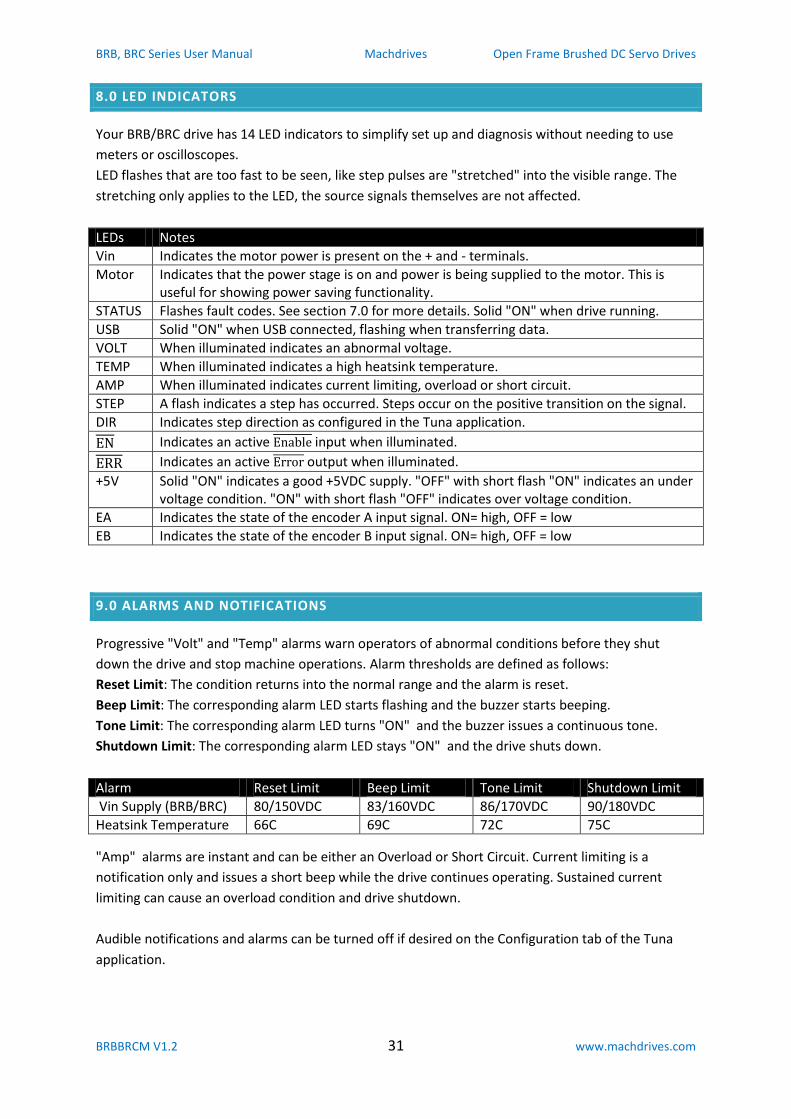
8.0 LED INDICATORS
Your BRB/BRC drive has 14 LED indicators to simplify set up and diagnosis without needing to use
meters or oscilloscopes.
LED flashes that are too fast to be seen, like step pulses are "stretched" into the visible range. The
stretching only applies to the LED, the source signals themselves are not affected.
LEDs Notes
Vin Indicates the motor power is present on the + and - terminals.
Motor Indicates that the power stage is on and power is being supplied to the motor. This is useful for showing power saving functionality.
STATUS Flashes fault codes. See section 7.0 for more details. Solid "ON" when drive running.
USB Solid "ON" when USB connected, flashing when transferring data.
VOLT When illuminated indicates an abnormal voltage.
TEMP When illuminated indicates a high heatsink temperature.
AMP When illuminated indicates current limiting, overload or short circuit.
STEP A flash indicates a step has occurred. Steps occur on the positive transition on the signal.
DIR Indicates step direction as configured in the Tuna application.
Indicates an active input when illuminated.
Indicates an active output when illuminated.
+5V Solid "ON" indicates a good +5VDC supply. "OFF" with short flash "ON" indicates an under voltage condition. "ON" with short flash "OFF" indicates over voltage condition.
EA Indicates the state of the encoder A input signal. ON= high, OFF = low
EB Indicates the state of the encoder B input signal. ON= high, OFF = low
9.0 ALARMS AND NOTIFICATIONS
Progressive "Volt" and "Temp" alarms warn operators of abnormal conditions before they shut
down the drive and stop machine operations. Alarm thresholds are defined as follows:
Reset Limit: The condition returns into the normal range and the alarm is reset.
Beep Limit: The corresponding alarm LED starts flashing and the buzzer starts beeping.
Tone Limit: The corresponding alarm LED turns "ON" and the buzzer issues a continuous tone.
Shutdown Limit: The corresponding alarm LED stays "ON" and the drive shuts down.
Alarm Reset Limit Beep Limit Tone Limit Shutdown Limit
Vin Supply (BRB/BRC) 80/150VDC 83/160VDC 86/170VDC 90/180VDC
Heatsink Temperature 66C 69C 72C 75C
"Amp" alarms are instant and can be either an Overload or Short Circuit. Current limiting is a
notification only and issues a short beep while the drive continues operating. Sustained current
limiting can cause an overload condition and drive shutdown.
Audible notifications and alarms can be turned off if desired on the Configuration tab of the Tuna
application.
BRB, BRC Series User Manual Machdrives Open Frame Brushed DC Servo Drives
BRBBRCM V1.2 32 www.machdrives.com
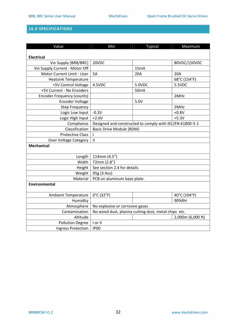
10.0 SPECIFICATIONS
Value Min Typical Maximum
Electrical
Vin Supply (BRB/BRC) 20VDC 80VDC/150VDC
Vin Supply Current - Motor Off 15mA
Motor Current Limit - User 5A 20A 20A
Heatsink Temperature 68°C (154°F)
+5V Control Voltage 4.5VDC 5.0VDC 5.5VDC
+5V Current - No Encoders 50mA
Encoder Frequency (counts) 2MHz
Encoder Voltage 5.0V
Step Frequency 2MHz
Logic Low Input -0.3V +0.8V
Logic High Input +2.6V +5.3V
Compliance Designed and constructed to comply with IEC/EN 61800-5-1
Classification Basic Drive Module (BDM)
Protective Class I
Over Voltage Category II
Mechanical
Length 114mm (4.5")
Width 72mm (2.8")
Height See section 2.4 for details.
Weight 95g (3.4oz)
Material PCB on aluminum base plate.
Environmental
Ambient Temperature 0°C (32°F) 40°C (104°F)
Humidity 90%RH
Atmosphere No explosive or corrosive gases
Contamination No wood dust, plasma cutting dust, metal chips etc.
Altitude 2,000m (6,000 ft)
Pollution Degree I or II
Ingress Protection IP00