Embed Size (px)
Citation preview

1
The 4th International Symposium - Supercritical CO2 Power Cycles September 9-10, 2014, Pittsburgh, Pennsylvania
UTILIZATION OF THE SUPERCRITICAL CO 2 BRAYTON CYCLE WITH SODIUM-COOLED FAST REACTORS
James J. Sienicki Manager, Innovative Systems and Engineering
Assessments Argonne National Laboratory
Argonne, Illinois USA [email protected]
Lubomir Krajtl Designer
Argonne National Laboratory Argonne, Illinois USA
Anton Moisseytsev Principal Computational Engineer
Argonne National Laboratory Argonne, Illinois USA [email protected]
James J. Sienicki is the Manager of the Innovative Systems and Engineering Assessments Section and a Senior Nuclear Engineer in the Nuclear Engineering Division at Argonne National Laboratory (ANL). He has been leading the development of the supercritical carbon dioxide Brayton cycle at ANL with funding from the U.S. Department of Energy since 2002. He is also involved in the design and analysis of experiments on fundamental phenomena involved in heat exchangers for supercritical CO2 cycles.
Anton Moisseytsev is a Principal Computational Nuclear Engineer in the Nuclear Engineering Division at ANL. He has ten years of experience in modeling and simulation of various systems, including design and analysis of the advanced reactors and energy conversion systems, safety analysis of nuclear reactors, and code development for steady-state and transient simulations of nuclear power plants. Anton has been involved in the development of the supercritical carbon dioxide Brayton cycle at Argonne since 2002.
Lubomir Krajtl is a Designer in the Nuclear Engineering Division at ANL. He has twenty-five years of experience in the design of electrorefiners for Sodium-Cooled Fast Reactor metallic fuel, various Sodium-Cooled Fast Reactors including the AFR-100, as well as sodium and supercritical CO2 experiment facilities.

2
ABSTRACT
The supercritical carbon dioxide (S-CO2) Brayton cycle is well matched to the Sodium-Cooled Fast Reactor (SFR) nuclear power reactor system and offers significant benefits for SFRs. The recompression closed Brayton cycle wants to operate with a S-CO2 temperature rise in the sodium-to-CO2 heat exchangers of about 150 °C which is well matched to the sodium temperature rise through the core that is also about 150 °C. For a core outlet temperature of 550 °C, a cycle efficiency of 42.3 % is calculated that exceeds that obtained with a traditional superheated steam cycle by one percentage point or more. Use of the S-CO2 Brayton cycle eliminates sodium-water reactions and can reduce the nuclear power plant cost per unit electrical power. The S-CO2 Brayton cycle with its automatic control strategy and active reactor control enables load following down to zero load demand and can continue to be used to remove heat from the reactor down to initial decay heat levels. A conceptual design of an optimized S-CO2 Brayton cycle power converter and supporting systems has been developed for the Advanced Fast Reactor – 100 (AFR-100) 100 MWe-class SFR Small Modular Reactor (SMR). The components and cycle conditions were optimized to minimize the power plant cost per unit electrical power (i.e., $/kWe). The S-CO2 Brayton cycle power converter is found to have a small footprint reducing the space requirements for components and systems inside of both the turbine generator building and reactor building. The results continue to validate earlier notions about the benefits of S-CO2 Brayton cycle power conversion for SFRs.
BACKGROUND
The supercritical carbon dioxide (S-CO2) Brayton cycle is well matched to the Sodium-Cooled Fast Reactor (SFR) nuclear power reactor system for which the core outlet temperature could be as high as 550 °C. The recompression closed Brayton cycle wants to operate with a S-CO2 temperature rise in the sodium-to-CO2 heat exchangers of about 150 °C which is well matched to the sodium temperature rise through the core that is also about 150 °C. For a core outlet temperature of 550 °C, the turbine inlet temperature might be 517 °C for which a greater cycle efficiency of 42.3 % is calculated that exceeds that obtained with a traditional superheated steam cycle by one percentage point or more. Use of a S-CO2 cycle instead of a traditional superheated steam cycle eliminates sodium-water reactions which reduces the power plant cost by eliminating equipment otherwise needed to detect and accommodate sodium-water reactions that produce flammable H2 gas. However, there remains a need to detect and accommodate sodium-CO2 interactions that are expected to be more benign than sodium-water reactions but which can produce flammable CO gas and solid reaction products. The smaller turbomachinery of the S-CO2 cycle combined with the use of compact heat exchangers is expected to result in a smaller balance-of-plant footprint reducing the size of the turbine generator building and portions of the reactor building. The S-CO2 Brayton cycle is expected to reduce the SFR capital cost per unit output electrical power ($/kWe) or the Levelised Cost of Energy over the power plant lifetime. Thus, a distinct benefit is foreseen in application of the S-CO2 Brayton cycle to SFRs. Twelve years of experience at Argonne National Laboratory (ANL) working on development of the S-CO2 Brayton cycle continues to confirm the initial notions about the benefits of the S-CO2 Brayton cycle for SFRs and other advanced nuclear reactors.
Analyses with the ANL Plant Dynamics Code coupled to the SAS4A/SASSYS-1 Liquid Metal Reactor Analysis Code System have shown that a SFR with a S-CO2 Brayton cycle power converter can be controlled and perform load following over the full range of grid demand from 100 to 0 % nominal demand (Moisseytsev and Sienicki, 2014). Following disconnection from the electrical grid, the cycle can be utilized to continue to remove heat from the SFR and reject it to the heat sink with the turbine driving the two compressors on a common shaft. Through a combination of shaft speed control and active control of the reactor power and primary and intermediate sodium pump speeds, heat removal using the cycle can be accomplished down to initial decay heat levels of at least as low as 3 % nominal, if not even lower (Moisseytsev and Sienicki, 2014).
S-CO2 BRAYTON CYCLE FOR THE AFR-100
The Advanced Fast Reactor-100 (AFR-100) is a 100 MWe-class SFR Small Modular Reactor (SMR) under ongoing development at ANL to target emerging markets where a clean, secure, and stable source of electricity is required but a large-scale power plant cannot be accommodated (Grandy et. al, 2013).

3
The AFR-100 incorporates options and innovative fast reactor technologies that have been investigated or are being developed under U.S. Department of Energy programs to achieve capital cost reductions, increase passive safety, and improve core performance. One such innovation is adoption of S-CO2 Brayton cycle power conversion with the superheated steam cycle as a backup.
Modeling incorporated into the ANL Plant Dynamics Code was used to optimize the conceptual design of compact diffusion-bonded heat exchangers and turbomachinery as well as overall cycle conditions to minimize the AFR-100 capital cost per unit output electrical power (i.e., $/kWe). For example, by increasing the size and effectiveness of the heat exchangers, the cycle and net plant efficiencies can be increased. However, the power converter cost also rises. There is an optimum size for each heat exchanger that minimizes the plant capital cost per unit output electrical power. The resulting cycle conditions are shown in Figure 1. For a nominal thermal power of 250 MWt input to the cycle, a gross cycle efficiency of 42.3 % is calculated for which the electrical power output of the generator is 105.7 MWe. The net efficiency will be less due to the electrical power demands of the circulating water pumps, the primary and intermediate sodium pumps, as well as other electrical power consumers.
Optimized conditions for the heat exchangers are presented in Table 1. The heat exchangers are modeled as compact diffusion-bonded heat exchangers manufactured from Type 316 stainless steel. Each heat exchanger consists of a number of individual diffusion-bonded blocks assumed to be limited in dimensions to 1.50 m maximum by 0.6 m maximum by 0.6 m maximum. The number of piping connections to the blocks can be significantly reduced by welding individual blocks together side-by-side and then welding manifolds to the welded block assembly to produce a small number of transportable heat exchanger modules. This is illustrated in Figure 2 for the sodium-to-CO2 heat exchanger. Optimized conditions for the turbine and compressors are provided in Table 2.
Figure 3 shows the flow diagram developed for the S-CO2 Brayton cycle power converter. The flow diagram includes two normal shutdown heat removal systems that also utilize supercritical CO2 as the heat exchange fluid as well as the CO2 charging system. A normal shutdown heat removal loop is provided for each of the two intermediate sodium loops. Each normal shutdown heat removal system is sized to remove 5 % of the nominal reactor power (i.e., 12.5 MWt) and serves to cool the reactor when it is shut down and the S-CO2 Brayton cycle is also shut down or otherwise unavailable due to the need for maintenance or repair. The normal shutdown heat removal systems are separate from the AFR-100 emergency decay heat removal systems that consist of three NaK decay heat removal loops each of which incorporates a sodium-to-NaK Direct Reactor Auxiliary Cooling System (DRACS) heat exchanger immersed inside of the primary sodium in the cold pool of the reactor vessel. Each normal shutdown heat removal loop uses supercritical CO2 for which the pressure is maintained at 8.0 MPa by a pressurizer and the flow by a S-CO2 pump. Heat is removed from the intermediate sodium loop by a small compact diffusion-bonded sodium-to-CO2 heat exchanger separate from the main sodium-to-CO2 heat exchanger and rejected to circulating water by a small compact diffusion-bonded CO2-to-water heat exchanger separate from the main cooler. Conditions are shown Figure 4 and Table 3. The S-CO2 pump required to offset the pressure drops and deliver the required flowrate is determined to be a centrifugal pump with an impeller diameter of 0.261 m, rotational speed of 3,016 rpm, and 80 % efficiency.
The CO2 piping layout in Figure 3 is designed such that the rupture of any single CO2 pipe cannot disable more than one system among the S-CO2 Brayton cycle and the two normal shutdown heat removal loops. Cross connections enable either normal shutdown heat removal loop to also remove heat from the other intermediate sodium loop. Liquid CO2 is delivered by truck and stored inside of a liquid CO2 storage vessel in the turbine generator building. As needed, liquid CO2 is heated and delivered to the S-CO2 Brayton cycle and normal shutdown heat removal loops by a CO2 charging compressor. When the S-CO2 Brayton cycle or a normal shutdown heat removal loop needs to be depressurized and purged of CO2 for maintenance or repair, the CO2 is released to the atmosphere. There is no effort to capture and store the CO2 for reuse.

4
Figure 1. Optimized S-CO 2 Brayton Cycle Conditions for the AFR-100.

5
Table 1. Optimized S-CO 2 Brayton Cycle Heat Exchanger Conditions
Heat Exchanger Sodium -to-CO2 CO2-to -CO2 High Temperature Recuperator
CO2-to -CO2 Low Temperature Recuperator
CO2-to -Water Cooler
Heat Duty, MWt 250 338.2 156.4 137.2 Number of Diffusion-Bonded Blocks
96 48 48 72
Heat Duty per Block, MWt 2.60 7.05 3.26 1.91 Block Length/Width/Height, m
1.50/0.6/0.6 0.6/1.50/0.6 0.6/1.50/0.6 0.868/0.6/0.6
Channel Length for Heat Transfer Hot/Cold Side, m
1.500/1.732 0.439/0.439 0.439/0.537 0.748/0.715
Hot Side Channels 6 mm Wide by 4 mm High Rectilinear
1.3 mm Semicircular
1.3 mm Semicircular
2 mm Semicircular
Cold Side Channels 2 mm Semicircular
1.3 mm Semicircular
1.3 mm Semicircular
2 mm Semicircular
Hot Side Inlet/Outlet Temperature, °C
528.0/373.0 403.9/185.0 184.9/89.8 89.6/32.66
Cold Side Outlet/Inlet Temperature, °C
516.6/367.0 367.0/174.6 171.3/84.3 35.5/30.0
Hot Side Inlet/Outlet Pressure, MPa
0.100/0.100 7.722/7.696 7.682/7.666 7.635/7.628
Cold Side Outlet/Inlet Pressure, MPa
19.802/19.946 19.962/19.971 19.987/19.995 0.101/0.226
Hot/Cold Side Flowrate, kg/s
13.2/14.2 28.3/28.3 28.3/19.3 12.2/83.3
Block Mass, tonnes 1.701 2.653 2.653 1.586 Effectiveness, % 96.3 95.5 94.6 95.5
Figure 2. Illustration of Welding Together Individu al Diffusion-Bonded Blocks and Welding on Manifolds to Produce Transportable Heat Exchanger M odules for the Case of the Sodium-to-CO 2
Heat Exchanger.
CO2in
CO2out
0.6 m H
0.6 m W
Weld
CO2in
CO2out
4.8 m

6
Table 2. Optimized S-CO 2 Brayton Cycle Turbomachinery Conditions
Turbomachine Turbine Main Compressor Recompressing Compressor
Type Axial Centrifugal Centrifugal Power, MWt 164.4 26.41 28.53 Rotational Speed, rpm 3,600 3,600 3,600 Number of Stages 6 1 2 Axial Length without Casing, m 2.67 0.37 0.86 Diameter without Casing, m 0.89 1.90 2.03 Hub Radius Max/Min, cm 35.3/28.2 10.0/10.0 10.8/8.4 Blade Tip Radius Max/Min, cm 44.6/42.5 Impeller Radius Max/Min, cm 56.9/56.9 63.2/58.7 Blade Height Max/Min, cm 16.4/7.2 8.7/1.4 11.1/1.2 Blade Chord Max/Min, cm 10.9/7.4 Blade Length, Max/Min, cm 50.6/23.3 57.8/25.0 Inlet/Outlet Pressure, MPa 19.79/7.751 7.621/20.00 7.643/19.98 Inlet/Outlet Temperature, °C 516.6/403.9 32.79/84.3 89.66/182.0 Flowrate, kg/s 1360.5 952.2 435.4 Maximum Mach Number 0.38 0.47 0.50 Total-to-Static Efficiency, % 92.8 89.1 90.1

7
Figure 3. Flow Diagram for S-CO 2 Brayton Cycle Power Converter, S-CO 2 Normal Shutdown Heat
Removal Systems, and CO 2 Charging System.
Figure 4. Normal Shutdown Heat Removal System Condi tions.

8
Table 3. S-CO 2 Normal Shutdown Heat Removal System Heat Exchanger Conditions
Heat Exchanger Sodium -to-CO2 CO2-to -Water Cooler
Heat Duty, MWt 12.5 12.5 Number of Diffusion-Bonded Blocks 1 1 Heat Duty per Block, MWt 12.5 12.5 Block Length/Width/Height, m 0.4/1.14/0.6 0.35/0.537/0.6 Hot Side Channels 6 mm Wide by 4
mm High Rectilinear
2 mm Semicircular
Cold Side Channels 2 mm Semicircular
2 mm Semicircular
Hot Side Inlet/Outlet Temperature, °C 528.0/373.0 435.3/200.0 Cold Side Outlet/Inlet Temperature, °C 435.3/200.0 90.0/30.0 Hot/Cold Side Flowrate, kg/s 63.4/46.5 46.5/49.8 Hot/Cold Side Pressure Drop, kPa 0.04/98.6 58.4/11.5
A three-dimensional Computer Aided Design (CAD) model of the S-CO2 Brayton cycle is under ongoing development as part of a larger CAD model for the AFR-100 nuclear power plant. The CAD model is being used to explore different component and piping layouts and to determine the footprint/space requirements of different components and systems. A general view of the nuclear power plant is shown in Figure 5. Heat is rejected to the atmospheric heat sink by means of modular cooling towers. A cutaway view of the reactor building is provided in Figure 6 revealing the sodium-to-CO2 heat exchanger modules located in a below-grade unsealed compartment of the reactor building below the operating floor. The sealed containment includes the upper compartment interior to the cylindrical wall and dome above the operating floor. This figure also shows two of the three NaK-to-air heat exchangers and stacks that are part of the three NaK emergency decay heat removal loops. A view of the sodium-to-CO2 heat exchanger modules in front of the guard vessel as well as the sodium and CO2 piping and other components is shown in Figure 7. Each intermediate sodium loop has four sodum-to-CO2 heat exchanger modules with each module incorporating twelve compact diffusion-bonded blocks welded together side-by-side. The space required for each set of four sodium-to-CO2 heat exchangers is less than that which would be required for steam generators, especially in the vertical direction. Moving around the reactor building in a counter-clockwise direction reveals the S-CO2 normal shutdown heat removal system components and piping for one of the intermediate sodium loops (Figure 8). Zooming out in Figure 9, one also observes the cooling tower module for that normal shutdown heat removal loop and interconnecting piping.

9
Figure 5. AFR-100 Nuclear Power Plant with Reactor Building and Turbine Generator Building in Foreground and Cooling Tower Modules in Background.

10
Figure 6. Reactor Building Showing Sodium-to-CO 2 Heat Exchanger Modules Located in Below-Grade Unsealed Compartment Below the Operating Floo r - Vessels in the Lowermost Unsealed
Compartment are the Intermediate Sodium Storage Ves sels.

11
.
Figure 7. Sodium-to-CO 2 Heat Exchanger Modules and Sodium and CO 2 Piping (Four Heat Exchanger Modules for Each Intermediate Sodium Loop ).
Figure 8. S-CO 2 Normal Shutdown Heat Removal System for One Interm ediate Sodium Loop (Left) – Primary Sodium Purification System is at Right.

12
Figure 9. S-CO 2 Normal Shutdown Heat Removal System for One Interm ediate Sodium Loop and Connection to Modular Cooling Tower - Sodium-to-CO 2 Heat Exchangers are Also Visible.
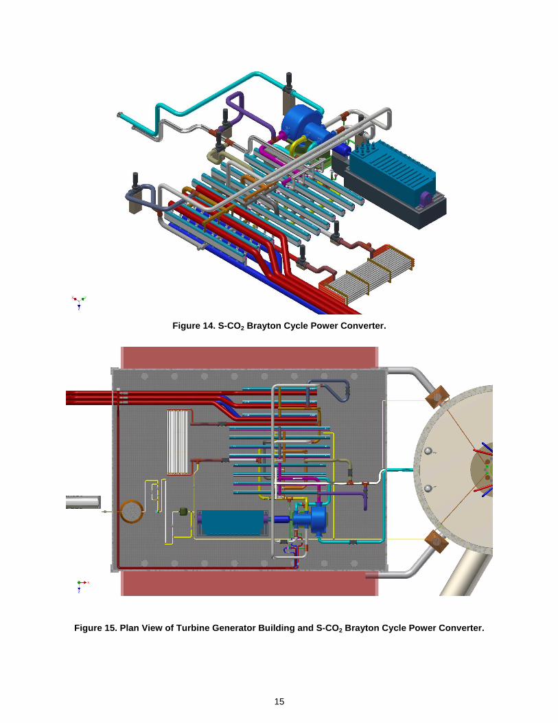
The S-CO2 Brayton cycle power converter is shown from various perspectives in Figure 10 through Figure 15. Because of the small size of the components, it is possible to install them upon a single level inside of the turbine generator building (Figure 10). The large vertical tank on the left side in Figure 10 and Figure 15 is the liquid CO2 storage tank. Liquid CO2 is delivered by truck as needed. In Figure 11 through Figure 15, the aqua colored pipe is the high temperature CO2 line from the sodium-to-CO2 heat exchangers to the turbine inlet and the silver line beneath it is the return lower temperature CO2 line. The inlet line is connected to the turbine which is housed inside of the larger diameter cylindrical casing. The main and recompressing compressors are housed inside of the smaller diameter casings on a common shaft that is also connected to a cylindrical startup motor and generator. The turbomachines are installed on reinforced concrete pads Adjacent to the linear turbomachinery train are installed the four heat exchanger modules comprising the CO2-to-CO2 high temperature recuperator. Each high temperature recuperator module consists of twelve diffusion-bonded blocks welded together side-by-side. The next four heat exchanger modules are the CO2-to-CO2 low temperature recuperator. The last three heat exchanger modules are the CO2-to-water cooler. Each cooler module is connected to large diameter inlet and outlet circulating water pipes; the red and blue pipes are the warmer outlet and cooler inlet circulating water pipes, respectively. The circulating water pipes connect to the cooling tower modules shown in Figure 5. The cooling tower modules are divided into three clusters with each cluster serving one of the CO2-to-water cooler modules. The cooling tower clusters are cross connected so that any cluster can be utilized to remove heat from any of the other two cooler modules (Figure 16). The horizontal vessels in the foreground in Figure 13 and Figure 14 are the inventory control system volume shown in Figure 3. Each inventory control vessel is a thick-walled pipe onto which hemispherical heads with nozzles are welded. The inner dimensions of the turbine generator building are 53 m (173 ft) length by 39 m (127 ft) width by 16 m (53 ft) height. The inner diameter of the reactor building cylindrical containment is 31 m (100 ft). The major components of the S-CO2 Brayton cycle from the inventory control volume vessels to the turbine fit inside of a footprint that is 32 m (106 ft) long by 33 m (109 ft) wide.

13
Figure 10. Turbine Generator Building with S-CO 2 Brayton Cycle Power Converter.
Figure 11. S-CO 2 Brayton Cycle Power Converter – CO 2 High Temperature Inlet Line from Sodium-to-CO 2 Heat Exchangers (Aqua) and CO 2 Return Line (Silver) Are at Lower Right.

14
Figure 12.S-CO 2 Brayton Cycle Power Converter - Circulating Water Lines to (Red) and from (Dark Blue) Cooling Tower Module Clusters Are at Lower Ri ght.
Figure 13. S-CO 2 Brayton Cycle Power Converter – Inventory Control System Vessels Are at Lower Left.
15
Figure 14. S-CO 2 Brayton Cycle Power Converter.
Figure 15. Plan View of Turbine Generator Building and S-CO 2 Brayton Cycle Power Converter.

16
Figure 16. AFR-100 Circulating Water Circuits Conne cting S-CO 2 Brayton Cycle and Normal Shutdown Heat Removal System Coolers with Modular C ooling Towers.
17
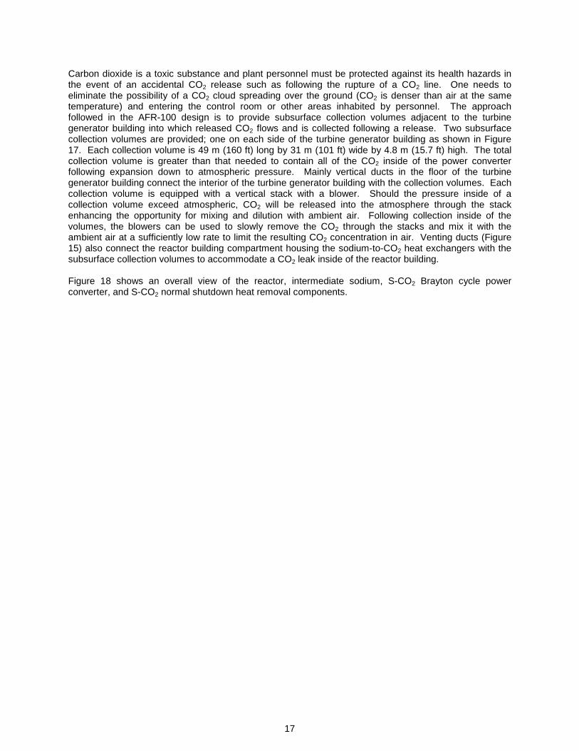
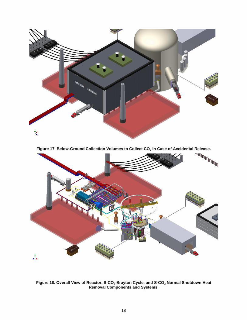
Carbon dioxide is a toxic substance and plant personnel must be protected against its health hazards in the event of an accidental CO2 release such as following the rupture of a CO2 line. One needs to eliminate the possibility of a CO2 cloud spreading over the ground (CO2 is denser than air at the same temperature) and entering the control room or other areas inhabited by personnel. The approach followed in the AFR-100 design is to provide subsurface collection volumes adjacent to the turbine generator building into which released CO2 flows and is collected following a release. Two subsurface collection volumes are provided; one on each side of the turbine generator building as shown in Figure 17. Each collection volume is 49 m (160 ft) long by 31 m (101 ft) wide by 4.8 m (15.7 ft) high. The total collection volume is greater than that needed to contain all of the CO2 inside of the power converter following expansion down to atmospheric pressure. Mainly vertical ducts in the floor of the turbine generator building connect the interior of the turbine generator building with the collection volumes. Each collection volume is equipped with a vertical stack with a blower. Should the pressure inside of a collection volume exceed atmospheric, CO2 will be released into the atmosphere through the stack enhancing the opportunity for mixing and dilution with ambient air. Following collection inside of the volumes, the blowers can be used to slowly remove the CO2 through the stacks and mix it with the ambient air at a sufficiently low rate to limit the resulting CO2 concentration in air. Venting ducts (Figure 15) also connect the reactor building compartment housing the sodium-to-CO2 heat exchangers with the subsurface collection volumes to accommodate a CO2 leak inside of the reactor building. Figure 18 shows an overall view of the reactor, intermediate sodium, S-CO2 Brayton cycle power converter, and S-CO2 normal shutdown heat removal components.
18
Figure 17. Below-Ground Collection Volumes to Colle ct CO 2 in Case of Accidental Release.
Figure 18. Overall View of Reactor, S-CO 2 Brayton Cycle, and S-CO 2 Normal Shutdown Heat Removal Components and Systems.

19
SUMMARY
The supercritical carbon dioxide (S-CO2) Brayton cycle is well matched to the Sodium-Cooled Fast Reactor (SFR) nuclear power reactor system and offers significant benefits for SFRs. The recompression closed Brayton cycle wants to operate with a S-CO2 temperature rise in the sodium-to-CO2 heat exchangers of about 150 °C which is well matched to the sodium temperature rise through the core that is also about 150 °C. For a core outlet temperature of 550 °C, a cycle efficiency of 42.3 % is calculated that exceeds that obtained with a traditional superheated steam cycle by one percentage point or more. Use of the S-CO2 Brayton cycle eliminates sodium-water reactions and can reduce the nuclear power plant cost per unit electrical power. The S-CO2 Brayton cycle with its automatic control strategy and active reactor control enables load following down to zero load demand and can continue to be used to remove heat from the reactor down to initial decay heat levels. A conceptual design of an optimized S-CO2 Brayton cycle power converter and supporting systems has been developed for the Advanced Fast Reactor – 100 (AFR-100) 100 MWe-class SFR Small Modular Reactor (SMR). The components and cycle conditions were optimized to minimize the power plant cost per unit electrical power (i.e., $/kWe). The S-CO2 Brayton cycle power converter is found to have a small footprint reducing the space requirements for components and systems inside of both the turbine generator building and reactor building. The results continue to validate earlier notions about the benefits of S-CO2 Brayton cycle power conversion for SFRs
REFERENCES
Grandy, C., Kim, T. K., Jin, E., Farmer, M., Belch, H., Grudzinski, J., Sumner, T., Momozaki, Y., Krajtl, L., Gerardi, C., Tang, Y., Moran, T., Moisseytsev, A., Vilim, R., Wei, T., Seidensticker, R., and Youngdahl, C., 2013, “Advanced Fast Reactor – 100 – Design Overview,” Paper 398, International Conference on Fast Reactors and Related Fuel Cycles: Safe Technologies and Sustainable Scenarios FR 13, Paris, France, March 4-7.
Moisseytsev, A. and Sienicki, J. J., 2014, “Recent Developments in S-CO2 Cycle Dynamic Modeling and Analysis at ANL,” The 4th International Symposium – Supercritical CO2 Power Cycles, Pittsburgh, Pennsylvania, September 9-10.
ACKNOWLEDGEMENTS
Argonne National Laboratory’s work was supported by the U. S. Department of Energy Advanced Reactor Technology (ART) Program under Prime Contract No. DE-AC02-06CH11357 between the U.S. Department of Energy and UChicago Argonne, LLC. The authors are grateful to Chris Grandy (ANL/NE), the Technical Area Lead and AFR-100 Principal Investigator, Bob Hill (ANL/NE), the National Technical Director, and Brian Robinson, the Headquarters Program Manager for the ART Program.