Embed Size (px)
Citation preview

LIOLD3_8/15
Brant Radiant Heaters, Ltd.
LD3 Series Gas-Fired Infrared Tube Heater
! WARNING
For Your Safety
If you smell gas: • Open windows.• Do not touch electrical switches.• Extinguish any open flame.• Immediately call your gas supplier from a neighbours phone.• Do not try to light any appliances.
This heater must be installed and serviced by trained gas installation and service personnel only. Failure to comply could result in personal injury, asphyxiation, death, fire or property damage.
Do not store or use gasoline or other flammable vapors and liquids in the vicinity of this or any other appliance. In locations used for the storage of combustible materials, signs must be posted to specify the maximum permissible stacking height to maintain the required clearances from the heater to the combustibles. Signs must either be posted adjacent to the heater thermostats or in the absence of such thermostats, in a conspicuous location.
Do not use this heater in indoor living or sleeping quarters, etc.! Installation of a tube heater system in residential indoor living spaces may result in property damage, serious injury, asphyxiation or death.
Consignes De Sécurité
Si vous sentez une odeur de gaz: • Ouvrez les fenêtres.• Ne touches pas aux interrupters électriques.• Éteignez toute flamme nue.• Contactez immediatement votre compagnie de gaz.
WARNING: Improper installation, adjustment, alteration, service or maintenance can cause property damage, injury or death. Read the installation, operating and maintence instructions thoroughly before installing or servicing this equipment.
AVERTISSEMENT. Une installation, un réglage, une modification, une réparation ou un entretien incorrect peut entraîner des dommages matériel, des blessures ou la mort. lisez attentivement les instructions d’installation, de fonctionnement et d’entretien avant de procéder à l’installation ou à l’entretien de cet équipement.
INSTALLER: Present this manual to the end user. Keep these instructions in a clean and dry place for future reference.
Model#: Serial #: (located on rating label)
Ce dispositif de chauffage doit être installé et entretenu par installation à gaz formés et seul le personnel de service. Le non-respect de ces instructions peut entraîner des blessures corporelles, d’asphyxie, de décès, d’incendie ou de dommages matériels.
Ne pas stocker ni utiliser de l’essence ou d’autres vapeurs inflammables et liquides dans le voisinage de ce ou de tout autre appareil. Dans lieux utilisés pour le stockage de matériaux combustibles, les affiches doivent être posées pour spécifier la hauteur d’empilage maximale admissible à maintenir les autorisations nécessaires de l’appareil de chauffage aux combustibles. Les panneaux doivent être soit posté adjacent à la thermostats du réchauffeur ou en l’absence de telles les thermostats, en un endroit bien en vue.
Ne pas utiliser cet élément chauffant en indoor vivant ou lieux de couchage, etc.! Installation d’un système de chauffage tube dans des espaces de vie à l’intérieur d’une résidence peut entraîner des dommages matériels et des blessures graves, l’asphyxie ou la mort.
! WARNING


3
LD3 Series 1.0 Introduction • Table of Contents
Contents1.0 Introduction . . . . . . . . . . . . . . . . . . . . . . . . . . . . . . . . . . . . . . . . . . . . . . . . . . . . . . . . . . . . . . . . . . . . . . 4 Overview . . . . . . . . . . . . . . . . . . . . . . . . . . . . . . . . . . . . . . . . . . . . . . . . . . . . . . . . . . . . . . . . . . . . . . . . . . 4
Heater Components . . . . . . . . . . . . . . . . . . . . . . . . . . . . . . . . . . . . . . . . . . . . . . . . . . . . . . . . . . . . . . . . . 4
Specifications. . . . . . . . . . . . . . . . . . . . . . . . . . . . . . . . . . . . . . . . . . . . . . . . . . . . . . . . . . . . . . . . . . . . . . . 5
Safety Signs and Labels . . . . . . . . . . . . . . . . . . . . . . . . . . . . . . . . . . . . . . . . . . . . . . . . . . . . . . . . . . . . . . 6
2.0 Safety . . . . . . . . . . . . . . . . . . . . . . . . . . . . . . . . . . . . . . . . . . . . . . . . . . . . . . . . . . . . . . . . . . . . . . . . . . . 8 Warning Symbols. . . . . . . . . . . . . . . . . . . . . . . . . . . . . . . . . . . . . . . . . . . . . . . . . . . . . . . . . . . . . . . . . . . . 8
Applications . . . . . . . . . . . . . . . . . . . . . . . . . . . . . . . . . . . . . . . . . . . . . . . . . . . . . . . . . . . . . . . . . . . . . . . . 8
Standards, Certifications and Government Regulations . . . . . . . . . . . . . . . . . . . . . . . . . . . . . . . . . . . . . 9
Clearance to Combustibles . . . . . . . . . . . . . . . . . . . . . . . . . . . . . . . . . . . . . . . . . . . . . . . . . . . . . . . . . . . .11
3.0 Installation . . . . . . . . . . . . . . . . . . . . . . . . . . . . . . . . . . . . . . . . . . . . . . . . . . . . . . . . . . . . . . . . . . . . . . 13 Design Considerations and Prechecks. . . . . . . . . . . . . . . . . . . . . . . . . . . . . . . . . . . . . . . . . . . . . . . . . . 14
Recommended Mounting Heights and Coverages . . . . . . . . . . . . . . . . . . . . . . . . . . . . . . . . . . . . . . . . 15
Hanger Placement and Suspension . . . . . . . . . . . . . . . . . . . . . . . . . . . . . . . . . . . . . . . . . . . . . . . . . . . 16
Radiant Tube Assembly. . . . . . . . . . . . . . . . . . . . . . . . . . . . . . . . . . . . . . . . . . . . . . . . . . . . . . . . . . . . . . 20
Optional Elbow or U-Bend Accessory Configuration . . . . . . . . . . . . . . . . . . . . . . . . . . . . . . . . . . . . . . . 21
Burner Control Box Suspension . . . . . . . . . . . . . . . . . . . . . . . . . . . . . . . . . . . . . . . . . . . . . . . . . . . . . . . 23
Reflector Assembly . . . . . . . . . . . . . . . . . . . . . . . . . . . . . . . . . . . . . . . . . . . . . . . . . . . . . . . . . . . . . . . . . 24
Final Heater Assembly. . . . . . . . . . . . . . . . . . . . . . . . . . . . . . . . . . . . . . . . . . . . . . . . . . . . . . . . . . . . . . . 26
Venting . . . . . . . . . . . . . . . . . . . . . . . . . . . . . . . . . . . . . . . . . . . . . . . . . . . . . . . . . . . . . . . . . . . . . . . . . . . 27
Optional Unvented Operation . . . . . . . . . . . . . . . . . . . . . . . . . . . . . . . . . . . . . . . . . . . . . . . . . . . . . . . . . 34
Combustion Air Requirements . . . . . . . . . . . . . . . . . . . . . . . . . . . . . . . . . . . . . . . . . . . . . . . . . . . . . . . . 35
Separated Combustion Systems. . . . . . . . . . . . . . . . . . . . . . . . . . . . . . . . . . . . . . . . . . . . . . . . . . . . . . . 36
Combustion Air Supply - Room Air . . . . . . . . . . . . . . . . . . . . . . . . . . . . . . . . . . . . . . . . . . . . . . . . . . . . . 37
Gas Supply Installation Instructions . . . . . . . . . . . . . . . . . . . . . . . . . . . . . . . . . . . . . . . . . . . . . . . . . . . . 38
Electrical Requirements and Wiring Diagrams . . . . . . . . . . . . . . . . . . . . . . . . . . . . . . . . . . . . . . . . . . . . 43
Typical Field Wiring . . . . . . . . . . . . . . . . . . . . . . . . . . . . . . . . . . . . . . . . . . . . . . . . . . . . . . . . . . . . . . . . . 44
Thermostat Connection . . . . . . . . . . . . . . . . . . . . . . . . . . . . . . . . . . . . . . . . . . . . . . . . . . . . . . . . . . . . . . 44
Unit Start-up (Commissioning) . . . . . . . . . . . . . . . . . . . . . . . . . . . . . . . . . . . . . . . . . . . . . . . . . . . . . . . . 46
High Altitude Operation . . . . . . . . . . . . . . . . . . . . . . . . . . . . . . . . . . . . . . . . . . . . . . . . . . . . . . . . . . . . . . 50
4.0 Operation . . . . . . . . . . . . . . . . . . . . . . . . . . . . . . . . . . . . . . . . . . . . . . . . . . . . . . . . . . . . . . . . . . . . . . . 51 Operating Instructions . . . . . . . . . . . . . . . . . . . . . . . . . . . . . . . . . . . . . . . . . . . . . . . . . . . . . . . . . . . . . . . 51
Sequence of Operation . . . . . . . . . . . . . . . . . . . . . . . . . . . . . . . . . . . . . . . . . . . . . . . . . . . . . . . . . . . . . . 52
Diagnostics . . . . . . . . . . . . . . . . . . . . . . . . . . . . . . . . . . . . . . . . . . . . . . . . . . . . . . . . . . . . . . . . . . . . . . . 52
5.0 Maintenance . . . . . . . . . . . . . . . . . . . . . . . . . . . . . . . . . . . . . . . . . . . . . . . . . . . . . . . . . . . . . . . . . . . .54 Troubleshooting Guide . . . . . . . . . . . . . . . . . . . . . . . . . . . . . . . . . . . . . . . . . . . . . . . . . . . . . . . . . . . . . . 54
Routine Inspection. . . . . . . . . . . . . . . . . . . . . . . . . . . . . . . . . . . . . . . . . . . . . . . . . . . . . . . . . . . . . . . . . . 58
Heater Components and Parts List . . . . . . . . . . . . . . . . . . . . . . . . . . . . . . . . . . . . . . . . . . . . . . . . . . . . . 60
Limited Warranty . . . . . . . . . . . . . . . . . . . . . . . . . . . . . . . . . . . . . . . . . . . . . . . . . . . . . . . . . . . . . . . . . . . 62
Kit Contents . . . . . . . . . . . . . . . . . . . . . . . . . . . . . . . . . . . . . . . . . . . . . . . . . . . . . . . . . . . . . . . . . . . . . . . 64

1.0 Introduction
4
LD3 Series
Overview
The intent of this manual is to provide information regarding safety, design guidelines, installation, operation and maintenance of the tube heater. You must read and understand the instructions and all safety warnings before installing the tube heater. This manual is property of the owner, and must stay with the owner or unit after the installation is complete.
Heater Components
Prior to installation, verify that the heater’s gas type and voltage (as listed on the rating plate) match that of your application. Also verify that you have received all heater contents included with your tube heater. Reference the last page for a list of the kit contents for your model heater. Materials not included in the heater kit contents (e.g., screws, vent material, terminals, etc.) are the responsibility of the installer. Notify your product representative or Brant Radiant Heaters Ltd. of any discrepancy or missing kit contents prior to installing unit.
1.0 Introduction • Overview • Heater Components
Tube Hanger
Reflector
Reflector Center Support
10 ft. Primary/ Secondary Combustion Chamber(s)
Baffles
Reflector End Cap with Clips
Tube Clamp
Burner Control Box
Type 1 Rubber Hose
Radiant Tube(s)
Figure 1.1 • Heater Components*
Igniter/Sensor Box
Chains are not provided in kit. Optional accessory. P/N: THCS
16 in. Burner Tube
* Not all items illustrated may be provided with your heater. Refer to kit contents of the last page of the Series Manual.
Tube Hanger

5
LD3 Series
Mo
del
N
um
ber
Gas
Typ
e (s
elec
t on
e)
Max
imum
Inpu
t (B
TU/h
)
Min
imum
Inpu
t(B
TU/h
)
Str
aigh
t Len
gth
U-T
ube
Leng
th
Sta
ndar
d W
eigh
t (lb
s.)
Rec
omm
ende
d M
ount
ing
Hei
ght*
*
Com
bust
ion
Cha
mbe
r (B
lack
Coa
ted)
Rad
iant
Em
itter
Tub
e(s)
(B
lack
Coa
ted)
Res
iden
tial
Cer
tifica
tion^
LD3-15-40 N or LP 40,000 28,000 16’-10” N/A 85 lbs. 8’ to 13’ Titan Alum Yes
LD3-15-50 N or LP 50,000 35,000 16’-10” N/A 85 lbs. 10’ to 15’ Titan Alum No
LD3-20-40 N or LP 40,000 28,000 21’-10” 13’-0” 100 lbs. 8’ to 13’ Titan Alum Yes
LD3-20-50 N or LP 50,000 35,000 21’-10” 13’-0” 100 lbs. 9’ to 15’ Titan Alum No
LD3-30-50* N or LP 50,000 35,000 31’-7” 17’-8” 120 lbs. 9’ to 14’ Titan Alum Yes
Chart 1.1 • LD3 Series Specifications
* Model requires DB-5EA-SUB optional accessory package when installing in a ‘U’ configuration (P/N: DB-TF1B).** Recommended mounting heights are provided as a guideline. Actual conditions may dictate variations from this data. Optional protective guard (P/N: PG) is required when mounting below 8-ft.^ Certified models may be installed in attached residential garages/workshops.
Titan = Black coated titanium stabilized aluminized steel.Alum = Black coated aluminized treated steel.
Specifications
1.0 Introduction • Specifications

WARNING!
6
LD3 Series1.0 Introduction • Safety Signs and Labels
Safety Signs and Labels
Product safety signs or labels should be replaced by the product user when they no longer are legible. Contact either your local distributor or the product manufacturer for obtaining replacement signs or labels.
Read and understand all safety information and warnings in this manual before installation, operation and maintenance of the radiant tube heater system.
SE
RV
ICE
AC
CE
SS
PA
NE
LC
ON
TR
OL
S &
GA
S V
ALV
E C
OM
PA
RT
ME
NT
1. D
isco
nnect
gas
& e
lect
rici
ty.
2. R
em
ove
four
(4)
thum
bsc
rew
s.3. R
em
ove
top c
ove
r.4. S
win
g h
inged p
anel d
ow
nw
ard
.
KE
EP
CO
VE
R I
N P
LA
CE
. R
EM
OV
E F
OR
SE
RV
ICE
ON
LY.S
ER
VIC
E A
CC
ES
S P
AN
EL
FA
N C
OM
PA
RT
ME
NT
1. D
isconnect g
as &
ele
ctricity.2. R
em
ove
top co
ver (2
thum
bscre
ws).
3. R
em
ove
tsix (6) 1
/4” scre
ws.
4. L
ift and re
move
panel.
KE
EP
CO
VE
R IN
PL
AC
E. R
EM
OV
E F
OR
SE
RV
ICE
ON
LY.
Top Panel
F/N: LLTCL006L/C/R Clearance to Combustibles Label.
Bottom Panel
F/N: LLLOGO1 Logo Label
3
F/N: LLAC023 Combustion Air
Connector Label
NEUTRAL
EARTH
HOT
- 120V HEATER INPUT -
120V
F/N: LLV3EP1
F/N: LLV3EP14
Back Panel
Do not Rotate/ Gas hose label
! WARNINGImproper installation, adjustment, alteration, service or maintenance can cause property damage, injury or death.
LLTCL006L-1M-10/13 (CDS)
Read and understand the installation, operating and maintenance instructions thoroughly before installing or servicing this equipment.
Des installation réglage, modification, maintenance ou entretien inappropriés peuvent causer des dommages matériels, des blessures ou la mort.
Lire et comprendre les directives d’installation, de fonctionnement et d’entretien avant d’installer ou d’entretenir cet équipement.
Ce dispositif de chauffage doit être installé et entretenu par du gaz formés d'installation et le personnel de service uniquement.
Ce dispositif de chauffage exige une nouvelle air de combustion pour un fonctionnement sûr et doit satisfaire à toutes les dispositions de la spécifié de combustion et les exigences de ventilation.
RACCORDEMENT GAZ allocations doit être faite pour le système de se développer. Flexible de raccordement de gaz de type approuvé est requis. Le connecteur doit être de type 1 flexible. Consulter le manuel pour obtenir des instructions supplémentaires.
AVERTISSEMENT : Le connecteur doit être installé dans un "U" de configuration. Utilisez uniquement le connecteur qui était meublée avec le chauffage.
This heater must be installed and serviced by tained gas installation and service personnel only.
Ce chauffage doit être installé et entretenu par devai installation de gaz et le personnel de service uniquement.
This is NOT an explosion-proof heater. Where there is the possibility of exposure to flammable vapours or dusts, consult the local fire marshall, your carrier or authorities for approval of the proposed installation.
VENTING. This heater must be properly connected to a manufacturer’s approved vent system.
L'aération. Ce chauffage doit être correctement connecté à un fabricant agréé système d'évent.
WARNING: Operation of this heater, when not connected to a properly installed and maintained venting system, can result in carbon monoxide (CO) poisoning and possible death.
AVERTISSEMENT : L'opération de ce chauffage, lorsqu'il n'est pas connecté à un correctement installés et entretenus système d'aération et peut entraîner de monoxyde de carbone (CO) l'empoisonnement et la mort.
This heater requires FRESH COMBUSTION AIR for safe operation and must meet all provisions of the specified combustion and ventilation requirements.
GAS CONNECTION Allowances must be made for the system to expand. A flexible gas connection of approved type is required. The connector shall be of Type 1 hose. Consult manual for further instructions.
WARNING: Connector must be installed in a “U” configuration. Use only the connector that was furnished with the heater.
with 1 side shieldwith 2 side shields
0°45°0°0°
20.3299.0673.6622.86
20.3220.3220.3222.86
10.1625.4010.1610.16
91.4491.4491.4491.44
LS3 (10,15) - 25LS3 (10,15) - 30
25,000 & 30,000 BTU/h MODELS
!
CLEARANCE TO COMBUSTIBLES (IN CM)
FIRE HAZARD. Always maintain published clearance to combustibles. In locations used for the storage of combustible materials, signs must be posted. Consult manual for additional guidelines.
DANGER
SIDE SIDE
TOP
BELOW
0° MOUNTING ANGLE
FRONT BEHIND
BELOW
45° MOUNTING ANGLE
TOP
BELOW
BEHINDFRONT
0° W/1 SIDE SHIELD
TOP
SIDE SIDE
BELOW
0° W/2 SIDE SHIELDS
TOP
IMPORTANT: Use high BTU output when determining clearances. The minimum end clearance for all models is 30.8 centimeters. Maximum mounting angle is 45°.
*The minimum top clearance for an uncovered U-bend or elbows is 45.72 centimeters. A U-bend or elbow less than 25.40 centimeters from the burner must have a reflector hood. Keep burner and reflector assembly clean and free of debris.
LLTCL006C-11/13
with 1 side shieldwith 2 side shields
0°45°0°0°
38.10147.32106.68
50.80
38.1020.3220.3250.80
15.2425.4015.2415.24
114.30114.30114.30114.30
LS3/LD3 (15,20) - 40
MODEL NUMBER(LENGTH) - MBH FRONT
SIDEBEHIND TOP* BELOW
MOUNTING ANGLE
with 1 side shieldwith 2 side shields20 ft. from burner
0°45°0°0°0°
27.9499.0673.6640.6417.78
27.9420.3220.3240.6417.78
15.2425.4015.2415.2415.24
121.92121.92121.92121.92
76.20
40,000 BTU/h MODELS
Keep cover in place. Remove for service only.Maintenir le couvercle en place. Déposer pour l'entretien uniquement.
LS3/LD3 (15,20,30) - 5050,000 BTU/h MODELS
ENDEND
RISQUE D’INCENDIE. Toujours respecter les dégagements prescrits de tout matériau combustible. Dans les endroits servant au stockage de matériaux combustibles, des écriteaux doivent en avertir. Se référer au manuel pour des directives supplémentaires.
IMPORTANT : utiliser la haute puissance BTU lors de la détermination des autorisations. Le minimum fin jeu pour tous les modèles est de 30,8 centimètres. Angle de montage maximum est de 45°.
Le minimum dégagement supérieur pour un découvert U-plier ou coudes est 45,72 centimètres. Une U-plier ou coude moins de 25,40 centimètres dans le brûleur doit avoir un réflecteur le capot. Garder brûleur et assemblage réflecteur propre et exempt de débris.
SAFETY INSTRUCTIONS
This appliance must be installed in accordance with the manufacturer’s instructions and local codes. In the absence of local codes, follow the National Fuel Gas Code, ANSI Z223.1 or the CAN/CGA B149 Installation codes.
LLTCL006R-1M-10/13 (CDS)
! CAUTION
Cet appareil doit être installé conformément aux instructions du fabricant et aux codes locaux. En l'absence de codes locaux, suivez la Nationale du gaz combustible Code, ANSI Z223.1 ou le CAN/CGA B149 codes d'installation.
Ce chauffage doit être installé à un minimum de 8 pieds au-dessus du sol/sol. Il peut être équipé d'un dispositif de protection (p/n : PG) de faible montage ou gardé les applications.
APPLICATION. Si cet appareil est installé dans un ou plusieurs des emplacements suivants, puis l'installation doit être conforme à la dernière édition de la norme.
ATTENTION : En raison de températures de surface élevées, garder les enfants, les vêtements et les matériaux combustibles. Ne pas stocker les éléments combustibles en dessous de l'unité. Toujours maintenir le publié jeux de combustibles.
Hangars d'aéronefs. ANSI/NFPA 409. Structures de stationnement. ANSI/NFPA 88A Les garages. ANSI/NFPA 30A.
A. This appliance does not have a pilot. It is equipped with an ignition device which automatically lights the burner. DO NOT attempt to light burner by hand.B. Before operating, smell all around the appliance area for gas. Be sure to smell next to the floor because some gases are heavier than air and will settle to the floor. What to do if you smell gas:• Do not try to light any appliance.• Do not touch any electrical switch.• Do not use any phone in the building.• Immediately call your gas supplier from a neighbour’s phone. Follow gas supplier’s instructions.C. Use only your hand to turn the manual shut-off knob. Never use tools. If the knob will not turn by hand, don’t try to repair it; call a certified gas technician. Force or attempted repair may result in fire or explosion. D. Do not use this appliance if any part has been under water. Immedi-ately call a qualified service technician to inspect the appliance and replace any part of the control system or gas control which has been under water. A. Cet appareil ne dispose pas d'un pilote. Il est équipé d'un dispositif d'allumage qui s'allume automatiquement le brûleur. Ne tentez pas de lumière brûleur à la main.B. Avant le fonctionnement, odeur tout autour de l'appareil zone pour le gaz. Assurez-vous d'odeur prochaine de la parole, parce que certains gaz sont plus lourdes que l'air et se régler sur le plancher.Que faire si vous avez une odeur de gaz : • ne pas essayer de mettre en lumière un quelconque appareil. • Ne touchez aucun commutateur électrique. • Ne pas utiliser n'importe quel téléphone dans le bâtiment. • Appeler immédiatement votre fournisseur de gaz d'un voisin du téléphone. Gaz Suivez les instructions du fournisseur.D. ne pas utiliser cet appareil si aucune pièce n'a été sous l'eau. Appelez immédiatement un technicien de maintenance qualifié pour inspecter l'appareil et remplacer toute partie du système de contrôle ou de commande du gaz qui a été sous l'eau.
This heater must be installed at a minimum of 8 ft. above the floor/ground level. It may be equipped with a protective guard (p/n: PG) for low mounting or guarded applications.APPLICATION. If this applicance is installed in one or more of the following locations, then the installation must be in accordance with the latest edition of the Standard.Aircraft Hangers. ANSI/NFPA 409 Parking Structures ANSI/NFPA 88A Repair Garages ANSI/NFPA 30ACAUTION: Due to high surface temperatures, keep children, clothing and combustible items below the unit. Always maintain the published clearances to combustibles.

7
LD3 Series 1.0 Introduction • Safety Signs and Labels
SERVICE ACCESS PANELIGNITER & FLAME SENSE COMPARTMENT
1. Disconnect gas & electricity.2. Remove cover by lifting top cover upward and outward.
CAUTION: HOT SURFACE.KEEP COVER IN PLACE. REMOVE FOR SERVICE ONLY.
MODEL /MODELE NO. INPUT BTU/H FOR USE WITHNATURAL GAS
RADIATEUR A INFRAROUGE A FAIBLE INTENSITE
VOLTS A.C.
STARTING AMPS.
RUNNING AMPS.
120~60Hz
4.8
1.1
MANIFOLD PRESSURE
MIN. INLET PRESSURE
ORIFICE SIZE
3.5” WC
5.0” WC
#3 D.M.S
HEATER TYPE
VERSION
MIN. MOUNTING ANGLE:
COMBUSTION CHAMBER:3” BC TITANIUM
FOR INDOOR USE
BRANT RADIANT HEATERS LIMITED34 SCOTT AVE., PARIS, ONTARIOTEL: 1-519-442-7823 WWW.BRANTRADIANT.COM
ANSI Z83.20b - 2011 CSA 2.32b - 2011 Low - Intensity Infrared Htr. ANS Z83.20b - 2011 CSA - 2011 Low - Intensity Infrared Htr.
SERIAL NO. 0870 XXXX XXXX 0001
RE-VERBER-RAY LOW INTENSITY INFRARED HEATER
FOR INDOOR INSTALLATION ONLY. NOT FOR USE IN RESIDENTIAL DWELLING.INSTALLATION À L’EXTÉRIEUR SEULEMENT. NE PAS INSTALLER DANS UN LOGEMENT.
MAX. MOUNTING ANGLE:
0 DEGREES
45 DEGREESFOR STAINLESS STEEL UPGRADES THE
COMBUSTION TUBE IS UPGRADED TO 409 STAINLESS STEEL.
C1
10/11
LD3-20-40N 40,000/25,000
Controls Compartment
Fan Compartment
Al-Ti Combustion Chamber
16” Burner Tube
Rating Plate
Aluminized Radiant Tube(s)(if applicable)
F/N: LLTCL015 Lighting Instructions
MODEL /MODELE NO. INPUT BTU/H FOR USE WITHNATURAL GAS
RADIATEUR A INFRAROUGE A FAIBLE INTENSITE
VOLTS A.C.
STARTING AMPS.
RUNNING AMPS.
120~60Hz
4.8
1.1
MANIFOLD PRESSURE
MIN. INLET PRESSURE
ORIFICE SIZE
3.5” WC
5.0” WC
#3 D.M.S
HEATER TYPE
VERSION
MIN. MOUNTING ANGLE:
COMBUSTION CHAMBER:3” BC TITANIUM
FOR INDOOR USE
BRANT RADIANT HEATERS LIMITED34 SCOTT AVE., PARIS, ONTARIOTEL: 1-519-442-7823 WWW.BRANTRADIANT.COM
ANSI Z83.20b - 2011 CSA 2.32b - 2011 Low - Intensity Infrared Htr. ANS Z83.20b - 2011 CSA - 2011 Low - Intensity Infrared Htr.
SERIAL NO. 0870 XXXX XXXX 0001
RE-VERBER-RAY LOW INTENSITY INFRARED HEATER
FOR INDOOR INSTALLATION ONLY. NOT FOR USE IN RESIDENTIAL DWELLING.INSTALLATION À L’EXTÉRIEUR SEULEMENT. NE PAS INSTALLER DANS UN LOGEMENT.
MAX. MOUNTING ANGLE:
0 DEGREES
45 DEGREESFOR STAINLESS STEEL UPGRADES THE
COMBUSTION TUBE IS UPGRADED TO 409 STAINLESS STEEL.
C1
10/11
LD3-20-40N 40,000/25,000
SAMPLE
F/N: LLTB025R
F/N: LLTB024LF/N: LLTB026
OPERATING INSTRUCTIONS
4. Open access panel.5. Turn the gas valve switch to the “OFF” position.6. Close and secure the access panel.
ON
OFF
Gas Inlet
Gas Control Switch Shown in “OFF” Position
TURN OFF GAS TO APPLIANCE
1. STOP! Read the safety information in manual. 2. Set the thermostat to the lowest setting.3. Turn off all electric power to the appliance.4. This appliance is equipped with an ignition
device which automatically lights the burner. Do not try to light the burner by hand.
5. Open the access panel.6. Move the gas control switch to the “OFF” position.7. Wait five (5) minutes to clear out any gas. If you
still smell gas STOP! Follow “B” in the safety information above on caution label. If you do not smell gas, proceed to the next step.8. Move the gas control switch to the “ON” position.9. Close and secure control access panel.
1. Set the thermostat to the lowest setting.2. Turn manual shut-off valve located outside of
the unit to the closed position.3. Turn off all electrical power to the appliance
if service is to be performed.
5. Ouvrez le panneau d'accès.6. Déplacer le gaz l'interrupteur sur la position “OFF ”.7. Attendre (5) cinq minutes pour effacer tout gaz. Si vous sentez encore gaz STOP ! Suivre “ B ” dans les informations de sécurité ci-dessus sur l'étiquette d'avertissement. Si vous ne sentez pas de gaz, passez à l'étape suivante.8. Déplacez le contrôle gaz interrupteur sur la position “ ON ”.9. Fermer et sécuriser le panneau d'accès.
10. Turn on all electric power to the appliance.11. Set thermostat to desired setting.12. If the appliance will not operate, follow the instructions “TO TURN OFF GAS TO THE APPLIANCE” and call your service technician or gas supplier.
10. Tourner sur l'alimentation électrique de l'appareil.11. Set thermostat au réglage désiré.12. Si l'appareil ne fonctionne pas, suivez les instructions “ Pour TURN OFF gaz à l'appareil ” et appelez votre fournisseur de gaz
ou de technicien de service.
1. Réglez le thermostat à réglage le plus bas.2. Tourner le robinet d'arrêt manuel situé à l'extérieur de l'appareil à la position fermée.3. Coupez l'alimentation électrique de l'appareil si le service doit s'exécuter.4. Panneau d'accès ouvert.5. Tournez le commutateur de robinet de gaz à la position “OFF”.6. Fermer et verrouiller le panneau d'accès.
1. STOP ! Lisez les informations de sécurité dans le manuel d'utilisation.2. Réglez le thermostat sur le réglage le plus bas.3. Désactiver toute l'énergie électrique de l'appareil.4. Cet appareil est équipé d'un dispositif d'allumage lequel allume automatiquement le brûleur. N'essayez pas d'allumer le brûleur à la main. Yellow Titanium Alloy Tube
for combustion tube

8
LD3 Series
Warning Symbols
Safety is the most important consideration during installation, operation and maintenance of the tube heater. You will see the following symbols and signal words when there is a hazard related to safety or property damage.
2.0 Safety • Warning Symbols • Applications
2.0 Safety
Warning indicates a potentially hazardous situation which, if not avoided, could result in death or injury.
Caution indicates a potentially hazardous situation which, if not avoided, could result in minor or moderate injury.
Notice indicates a potentially hazardous situation which, if not avoided, could result in property damage.
NOTICE
WARNING!
CAUTION!
WARNING!
Improper installation, adjustment, alteration, service or maintenance can cause property damage, serious injury or death. Read and understand, the installation, operating and maintenance instructions thoroughly before installing or servicing this equipment. Only trained, qualified gas installation and service personnel may install or service this equipment.
Applications
This is not an explosion proof heater. No tube heater may be used in a Class 1 or Class 2 Explosive environment. Consult your local Fire Marshall, insurance carrier and other authorities for approval if the proposed installation is in question.
Commercial / Industrial ApplicationsUnless otherwise indicated, tube heaters are designed and certified for use in industrial and commercial buildings, such as warehouses, manufacturing plants, aircraft hangars and vehicle maintenance shops. For maximum safety the building must be evaluated for potential problems before installing the heating system. A critical safety factor to consider before installation is the clearance to combustibles.
Residential ApplicationsOnly select LD3 Series models are Design Certified under CSA Requirements for residential radiant tube heaters (No. 7-89). Not for use in the residential indoor living areas or sleeping quarters.
Read and understand all safety information and warnings in this manual prior to installation, operation, and maintenance of this heater. Warnings indicate a potentially hazardous situation which, if not avoided, could result in injury or death.
Standards, Certifications and Government Regulations
Installation of this tube heater must conform with all applicable local, state and national specifications, regulations and building codes. Contact the local building inspector and/or fire Marshall for guidance.
In the absence of local codes, the installation must conform to the latest edition of:
United States: National Fuel Gas Code, ANSI Z223.1 (NFPA 54).
Canada: CAN/CGA B149.1 and .2, Canadian Electrical Code C22.1
Copies of the Standards can be viewed or purchased at www.nfpa.org or www.scc.ca.
Public Garages:
This heater must be installed in accordance with the latest edition of the Standard for Parking Structures, ANSI/NFPA 88A or the Code for Motor Fuel Dispensing Facilities and Repair Garages ANSI/NFPA 30A. In Canada, refer to CAN/CGA B149.1 and B149.2.
• Heaters must not be installed less than 8 ft. (2.4 m) above the floor. Minimum clearances to combustibles must be maintained from vehicles parked below the heater.
• When installed over hoists, minimum clearances to combustibles must be maintained from the upper most point of objects on the hoist.
Aircraft Hangars:
This heater must be installed in accordance with the latest edition of the Standard for Aircraft Hangars, ANSI/NFPA 409. In Canada, refer to CAN/CGA B149.1 and B149.2.
• In aircraft storage and servicing areas, heaters shall be installed at least 10 ft. from above the upper surface of wings or of the engine enclosures of the highest aircraft that may be housed in the hangar. The measurement shall be made from the wing or engine enclosure, whichever is higher from the floor, to the bottom of the heater.
• In areas adjoining the aircraft storage area (e.g., shops, offices) the bottom of heaters shall be installed no less than 8 ft. (2.4 m) above the floor.
• Suspended or elevated heaters shall be located in spaces where they shall not be subject to damage by aircraft, cranes, movable scaffolding or other objects.
Provisions shall be made to assure accessibility to suspended tube heaters for recurrent maintenance purposes.
9
LD3 Series 2.0 Safety • Standards, Certifications and Regulations
Not For Use in Indoor Living Spaces. Installing this unit in residential indoor living spaces or sleeping quarters, such as bedrooms or basements, may result in property damage, serious injury or death.
WARNING!

10
LD3 Series
Applicable authorities governing the manufacturing or installation of this infrared heater include (but are not limited to) the following organizations:
The tube heater must be electrically grounded in accordance with the following codes:
United States: Refer to National Electrical Code®, ANSI/NFPA 70 (latest edition). Wiring must conform to the latest edition of National Electrical Code®, local ordinances, and any special diagrams furnished.
Canada: Refer to Canadian Electrical Code CSA C22.1 Part 1 (latest edition).
Venting must be installed in accordance with the requirements within this manual and the following codes:
United States: Refer to NFPA 54/ANSI Z223.1 (latest edition), National Fuel Gas Code.
Canada: Refer to CAN/CGA B149.1 Installation Codes for Gas Burning Appliances.
High Altitude
Electrical
Venting
BuildingLocation
Guidelines
Chart 2.1 • Standards and Code Installation Guidelines • Building Location
Installation of this tube heater is approved, without modifications, for elevations up to 6,000 feet (1,829 m) MSL (sea level) in the United States. Contact the factory for installations above these elevations.
The type of gas appearing on the nameplate must be the type of gas used. Installation must comply with national and local codes and requirements of the local gas company.
Guidelines:
BuildingAspect
Codes and Guidelines
Chart 2.2 • Standards and Code Installation Guidelines • Building Aspect
Non-StandardBTU Gas Unless otherwise noted on the rating plate, this infrared heater is designed and orificed to
operate on standard BTU gas. Contact the factory if utilizing non-standard BTU gas.
Guidelines:
• IAS - International Approval Services.
• AGA - American Gas Association.
• IRSC- Infrared Heater Safety Council.
• NFPA - National Fire Protection Association.
• ANSI Z83.20b - American National Standards Institute.
• NFPA 54/ANSI Z223.1 - National Fuel Gas Code.
• CSA - Canadian Standards Association.
• OSHA - Occupational Safety & Health Administration.
2.0 Safety • Standards, Certifications and Regulations

Children and adults should be alerted to the hazards of high surface temperatures and should stay away to avoid burns or clothing ignition.
Young children should be carefully supervised when they are in the same space as the heater.
Clothing or other flammable materials should not be hung from the heater, or placed on or near the heater.
Any guard or other protective device removed for servicing the heater must be replaced prior to operating the heater.
Installation and repair should be done by a qualified service person. The heater should be inspected before use and at least annually by a qualified service person. More frequent cleaning may be required as necessary. It is imperative that the control compartment, air passageways and burner(s) of the heater be kept clean.
CAUTION!
11
LD3 Series
Hazards:For maximum safety the building must be evaluated for hazards before installing the heating system. Examples include, but are not limited to:
• Gas and electrical lines• Combustible and explosive materials• Chemical storage areas• Areas of high chemical fume concentrations• Provisions for accessibility to the heater• Adequate clearances around air openings• Combustion and ventilating air supply
2.0 Safety • Clearance to Combustibles
Clearance to Combustibles
A critical safety factor to consider before installation is the clearances to combustibles. Clearance to combustibles is defined as the minimum distance you must have between the tube surface, or reflector, and the combustible item. Considerations must also be made for moving objects around the tube heater. The following is a partial list of items to maintain clearances from:
WARNING!
Placement of explosive objects, flammable objects, liquids and vapors close to the heater may result in explosion, fire, property damage, serious injury or death. Do not store or use explosive objects, liquids and vapor in the vicinity the heater.
WARNING!
Placement of explosive objects, flammable objects, liquids and vapors close to the heater may result in explosion, fire, property damage, serious injury or death. Do not store or use explosive objects, liquids and vapor in the vicinity the heater.
• Paint • Parked vehicles • Gasoline • Storage racks
Combustible items: Moving Objects: • Wood • Overhead doors• Paper • Vehicle lifts• Fabric • Cranes• Chemicals • Hoists
When installing the tube heating system, the minimum clearances to combustibles for your Series tube heater and system configuration must be maintained. These distances are shown in Chart 2.3 and on the burner control box. If you are unsure of the potential hazards, consult your local fire marshall, fire insurance carrier or other qualified authorities on the installation of gas fired tube heaters for approval of the proposed installation.
• Vehicle parking areas• Vehicles with lifts or cranes• Storage areas with stacked materials• Lights• Sprinkler heads• Overhead doors and tracks• Dirty, contaminated environment

Model NumberMounting
Angle*
Sides
Front Behind Top Below40,000 BTU/h MODELS
LD3 (15, 20) - 40 [N, P] 0° 15 (38) 15 (38) 6 (15) 45 (114)45° 58 (147) 8 (20) 10 (25) 45 (114)
with 1 side shield 0° 42 (107) 8 (20) 6 (15) 45 (114) with 2 side shields 0° 20 (151) 20 (151) 6 (15) 45 (114)
50,000 BTU/h MODELSLD3 (15, 20, 30) - 50 [N, P] 0° 11 (28) 11 (28) 6 (15) 48 (122)
45° 39 (99) 8 (20) 10 (25) 48 (122) with 1 side shield 0° 29 (74) 8 (20) 6 (15) 48 (122) with 2 side shields 0° 16 (41) 16 (41) 6 (15) 48 (122) 20 ft. from burner 0° 7 (18) 7 (18) 6 (15) 30 (76)
Chart 2.3 • Clearance to Combustibles in Inches (cm) (see Figure 2.1 for Mounting Angles)
* Heaters mounted on an angle between 0° to 45° must maintain clearances posted for 0° or 45°; whichever is greater. NOTE: Use high BTU output when determining clearances. The minimum end clearance is 12 in.
Figure 2.1 • Mounting Angles
0° Mounting Angle 45° Mounting Angle
0° Mounting Anglewith 1 Side Shield
(P/N: SSE)
0° Mounting Anglewith 2 Side Shields
(P/N: SSE)
Side Side
Below
Top
Front Behind
Below
Top
Front Behind
Below
Top
Side Side
Below
Top
WARNING!
Failure to comply with the stated clearances to combustibles may result in in personal injury, property damage and/or death.
12
LD3 Series2.0 Safety • Clearance to Combustibles
In locations used for the storage of combustible materials, signs must be posted to specify the maximum permissible stacking height to maintain the required clearances from the heater to the combustibles. Signs must either be posted adjacent to the heater’s thermostat or in a conspicuous location.
The stated clearance to combustibles represents a surface temperature of 90°F (32°C) above room temperature. Building materials with a low heat tolerance (such as plastics, vinyl siding, canvas, tri-ply, etc.) may be subject to degradation at lower temperatures. It is the installer’s responsibility to assure that adjacent materials are protected from degradation.

13
LD3 Series
WARNING!
Improper installation, adjustment, alteration, service or maintenance can cause property damage, serious injury or death.
Read and understand, the installation, operating and maintenance instructions thoroughly before installing or servicing this equipment.
Only trained, qualified gas installation and service personnel may install or service this equipment.
Design Considerations and Prechecks
Placement of infrared heaters is influenced by many factors. Aside from safety factors, considerations such as the number of heater or vent elbows that are allowed, maximum vent lengths, ducting of combustion air and combining exhaust vents are a few examples. All installation manuals, along with national, state, provincial and local codes, address these issues. It is critical that you read, understand and follow all guidelines and instructions.
To ensure a properly designed heating system, a layout should be developed for the correct placement of the burner control box, tubes, vents and combustion air intake ducts. Inspect and evaluate the mounting conditions, vent locations, gas supply and wiring.
When designing an infrared radiant heating system, consider the following:
• Has the building’s heat loss been evaluated?
• Does the design meet the needs of the space?
• Have recommended mounting heights been observed?
• Have all clearance to combustible situations been observed?
• Is the supply (burner) end of the heater located where more heat is required?
• Is it best to offset the heaters and/or rotate the reflectors towards the heat zone?
• Are extra guards, side shields, ‘U’ or ‘L’ reflector covers required?
• Does the heater require outside fresh air for combustion?
• Is the environment harsh or contaminated (requiring outside air for combustion)?
• Are chemicals or vapors a concern (requiring outside air for combustion or additional ventilation)?
IMPORTANT: Fire sprinkler heads must be located at an appropriate distance from the heater. This distance may exceed the published clearance to combustibles as posted on the heater. Certain applications may require the use of high temperature sprinkler heads or relocation of the heaters.
Sprinkler systems containing propylene glycol or other flammable substances are not to be used in conjunction with this heater without careful consideration for and avoidance of potential fire or explosion hazards. For further information consult NFPA 13.
The effective infrared surface temperature of a person or object may be diminished with wind above 5 mph. The use of adequate wind barrier(s) may be required.
3.0 Installation
3.0 Installation • Design Considerations and Prechecks

14
LD3 Series
Design Scenario:
A tube heater system is being installed in a 90’ (L) x 50’ (W) x 14’ (H) space. Two overhead doors are located at one end and an equipment storage area on one side. The calculated heat load is 400,000 BTU/h.
Figure 3.1 • Poor Design
Figure 3.2 • Good Design
Doors and tracks
Too Cold Too Hot
Equipment storage
50’
80’ - 200,000 BTU (2 total)Doors and
tracks
90’
Doors and tracks
Doors and tracks
Equipment storage
Sidewall Vent (2 total)
• Two burners (200,000 BTU each) are placed at one end, opposite the area of highest demand
(e.g., overhead doors).
• Recommended mounting heights are not observed (see Chart 3.1).
• Produces an uneven heat distribution.
• Four burners (100,000 BTU each) are placed in each corner. Burner (hotter) ends direct heat to areas of
highest heat demand.
• Recommended mounting heights have been observed.
• Distributes heat more evenly.
Gas Supply
50’
90’Gas Supply
40’ - 100,000 BTU (4 total)
Poor Design
Good Design
When heated, materials high in hydrocarbons (solvents, paint thinner, mineral spirits, formaldehydes, etc.) can evaporate. This may result in odors or fumes being emitted into the environment. To correct this problem, clean the area and/or introduce additional ventilation. The heaters themselves, when installed and serviced in accordance with the installation manual, do not emit foul odors into the environment.
Better Heat Distribution
3.0 Installation • Design Considerations and Prechecks

15
LD3 Series
Factory recommended mounting heights are listed as a guideline. If infrared heaters are mounted to low or to high, they may result in discomfort or lack of heat. Brant Radiant Heaters Limited generally recommends observing the recommended mounting heights to optimize comfort conditions. However, certain applications such as spot heating, freeze protection, outdoor patio heating or very high ceilings may result in the heaters being mounted outside of the factory recommended mounting heights.* Optional protective guard (P/N: PG) is required when mounting below 8-ft.
Chart 3.1 • Recommended Mounting Heights and CoveragesNOTE: This chart is provided as a guideline. Actual conditions may dictate variation from this data.
Figure 3.3 • Mounting Height Dimensions • see chart 3.1 for dimensions
3.0 Installation • Recommended Mounting Heights
Dim. C
Dim. A
Dim. B
Dim. C
Dim. A
Note: Dimensions A, B & C are based upon heaters hung at the factory recommended mounting height.
Mo
del
Max
imu
m In
pu
t(B
TU
/h)
Rec
om
men
ded
M
ou
ntin
g H
eig
ht
(ft.
)*
Cov
erag
e A
rea
Str
aig
ht C
on
fig
. (L
xW)
Cov
erag
e A
rea
U-T
ub
e C
on
gfi
g.
(LxW
)
Dis
tan
ce B
etw
een
H
eate
rs (
ft.)
Dim
ensi
on
A
Dis
tan
ce B
etw
een
H
eate
r R
ows
(ft.
)D
imen
sio
n B
Max
imu
m D
ista
nce
B
etw
een
Hea
ters
an
d W
all (
ft.)
D
imen
sio
n C
15 ft. 40,000 8’ - 13’ 20’ x 12’ N/A 10’ - 20’ 20’ - 40’ 16’
50,000 10’ - 15’ 22’ x 15’ N/A 20’ - 30’ 30’ - 50’ 18’
20 ft. 40,000 8’ - 13’ 20’ x 13’ 12’ x 12’ 10’ - 20’ 20’ - 40’ 16’
50,000 9’ - 15’ 22’ x 15’ 12’ x 12’ 20’ - 30’ 30’ - 50’ 18’
30 ft. 50,000 9’ - 14’ 32’ x 15’ 15’ x 15’ 20’ - 30’ 30’ - 50’ 18’

WARNING!
16
LD3 Series
Suspension of the heater must conform to applicable codes referenced in the Safety section and these instructions.
1 Lay all radiant tubing out in the following order. Position tubes in approximate location (see Figure 3.2). • 10 ft. 4” to 3” O.D. titanium treated combustion chamber. • 3” O.D. aluminized radiant emitter tube(s) if applicable.
2 Connect the female end of the titanium combustion chamber to the 16” burner tube by using the 4” stainless steel tube clamp (TP-220).
Important! The 10 ft. 4” to 3” O.D. titanium alloy treated combustion chamber must be placed as the first tube downstream of the burner control box. The combustion chamber has an orange identification sticker located on the swaged end of the tube.
3 Place a 4” tube hanger (TP-19B) on the tapered titanium combustion chamber’s 4” O.D. end. The spacing between the burner control box mounting brackets and the 4” tube hanger should be 2’-4”.
4 Mark locations for hanging points.
NOTE: If the available hanging points do not allow for the recommended spacing then additional hangers (P/N: TP-1079) may be necessary.
• The spacing between the burner control box mounting brackets and the first hanger should be approximately 2’-4”. • The space between the first two hangers placed on the first tube, should be approximately 8’-10”. • The space between hangers thereafter, one per tube, should be approximately 9’-8”.
Hanger Placement and Suspension
Improper suspension of the tube heater may result in collapse and being crushed. Always suspend from a permanent part of the building structure that can evenly support the total force and weight of the heater.
Failure to maintain minimum clearance to combustibles may result in fire and/or explosion, property damage, serious injury or death. Always maintain minimum clearances and post clearance safety limit signs or the clearance safety tag where needed.
3.0 Installation • Hanger Placement and Suspension

2’ 4”
(71 cm)
16” Burner Tube
10 ft. 4” to 3” O.D. Tapered or 10 ft. 4” O.D. Titanium Treated Combustion Chamber
3” O.D. Aluminized Steel Radiant Emitter Tube(s) (if applicable)8’ 10”
(2.6 m)
9’ 8”
(2.9 m)
9’ 8”
(2.9 m)
Burner Control Box
Burner Control Box Suspension Points
Suspension Point
Igniter/ Sensor Box
3” or 4” Tube Clamp (TP-1077 or TP-21B)
4” Stainless Steel Tube Clamp (TP-220)
4” Tube Hanger (TP-19B)
3” or 4” Tube Hanger (TP-1079 or TP-19B)
Suspension Point
Suspension Point
Figure 3.4 • Heater Mounting Layout
NOTE: A label identifying the combustion chamber(s) is located on the tube(s).
17
LD3 Series
Chart 3.2 • Heater Mounting Requirements and Weights
* Refer to page 22 for U-bend configuration dimensions.
Mod
el
Dim
ensi
on*
Str
aigh
t Con
figur
atio
n
Sus
pens
ion
Poi
nts
Con
trol
Box
Sta
biliz
er
Shi
ppin
g W
eigh
t
Cha
in S
et Q
ty.
Str
aigh
t
Cha
in S
et Q
ty.
w/T
F1B
Opt
iona
l Bra
ss
Knu
ckle
(P
/N:B
K)
Opt
iona
l Sin
gle
Mou
nt B
rack
et
15 ft. 16’-10” 3 2 85 lbs. 5 6 3 N/A
20 ft. 21’-10” 3 2 100 lbs. 5 6 3 2
30 ft. 31’-7” 4 2 120 lbs. 6 7 4 N/A
3.0 Installation • Hanger Placement and Suspension

18
LD3 Series
5 S-Hook and #1 Double-Loop Chain
5 Prepare mounting surface, if necessary weld blocks, drill holes (see figure 3.3). NOTE: The burner control box and radiant tubes should be in straight alignment and level.
6 Fasten beam clamp, screw hook or other type of suspension anchor to hanging point.
7 Attach and close S-hook (P/N: S-Hook) and #1 double-loop chain (P/N: THCS) to anchor. Check that it is securely attached. NOTE: Threaded rod and turnbuckles may be used.
8 Attach hangers to chains. Adjust chain lengths until radiant tubing is level and equal weight distribution is achieved. Chains must be straight up and down. Do not install chains at an angle as this can result in tube warpage or separation.
Figure 3.5 • Mounting the Hangers
3 Wood Beam3 Concrete Beam
4 Beam Clamp
4 Screw Hook
4 Screw hook
with Locknut and Washer
5 Threaded Rod and Turnbuckle
6 Threaded Rod
6 Chain
3 I-Beam
4 Beam Clamp
6 Chain6 Chain
3 I-Beam
3.0 Installation • Hanger Placement and Suspension

19
LD3 Series
For 45 degree hanging angle use two S-hooks and two #1 double-loop chains.
For variety of hanging angles, use an optional Brass Knuckle (P/N: BK) fitting with a #1 double-loop chain and S-hook.
45°30°
15°
U-Tubes can be mounted at a 15, 30 or 45 degree angle with two suspension points, using two optional Brass Knuckle (P/N: BK) fittings, #1 double-loop chains and S-hooks.
U-Tubes can be mounted from a single suspension point using an optional Single Mounting Bracket (P/N: SMB) with five S-hooks and #1 double-loop chains.
Figure 3.6 • U-Tube Hanger Mounting Options
Figure 3.7 • Angled Hanger Mounting Options
Exhaust End
Single Mounting Bracket
Brass Knuckle
3.0 Installation • Hanger Placement and Suspension

20
LD3 Series
Radiant Tube Assembly
To install the radiant tubes:
1 Place tubes in hangers with the welded seam facing downward and the swaged end of the tube towards the exhaust end of the heater system (see Figure 3.6).
Refer to Chart 3.6 for tube installation sequence.
2 Slide tube clamps onto radiant tubes (see figure 3.9).
Figure 3.8 • Attach Hangers
Figure 3.9 • Attach Tube Clamps
Hanger
Welded seam faces down
Swaged End
Tube Clamp
Radiant Tube
NOTE: If the tube clamp comes apart, the spacer must be re-assembled with the spacer’s concave surface facing against the radiant tube surface.
Concave surface
3.0 Installation • Radiant Tube Assembly

21
LD3 Series
Optional Elbow or U-Bend Accessory Configuration
A 90 degree elbow or 180 degree U-bend accessory fitting may be installed in the radiant tube heating system. Refer to Chart 3.3 for minimum distance requirements from the burner control box.
When installing an Elbow or U-Bend Accessory Fitting:• The top clearance of an uncovered (no reflector) elbow or U-bend accessory fitting to combustibles is 18 in.
• If operating the heater un-vented, separate the intake air to the heater from its exhaust products a minimum of 4 ft., further separation may be necessary. Combustion air may also be supplied.
• A maximum of two 90° elbows or one 180° U-bend can be installed on a heater.
Figure 3.11 • Optional Tube Connections
3 Slip-fit the radiant tube sections together until tightly connected (install the swaged end of each tube towards exhaust end). NOTE: If it is difficult to mate the tubes, they may be installed incorrectly.
4 Center tube clamps over the seam where two radiant tube sections connect. If necessary, rotate tube clamps so they will not interfere with the reflector end caps during expansion and contraction of
the heater. 5 Tighten tube clamp bolts to secure. When proper compression is obtained (40-60 ft-lbs. torque) the
tube seam will create a visible mark on the tube clamp. NOTE: Excessive torque may damage the tube clamp.
6 Determine the location of the burner control box and note the placement of the mounting chains.
Figure 3.10 • Tube Connections
Tubes fit snuggly together and the tube clamp is centered over the seam.
Tubes are not fit snuggly together and the tube clamp is not centered over the seam.
The tube clamp is tight when the torque is achieved (normally
when seam becomes visible).
Correct Tube Connection Incorrect Tube Connection
3.0 Installation • Tubes: Optional Elbow or U-Bend Accessory Configuration
90 Degree3” Elbow
(P/N: DB-E6)
180 Degree 3” U-Bend
(P/N: DB-TF1B)

22
LD3 Series3.0 Installation • Optional Elbow or U-Bend Accessory Configuration
* The LV3-5EA-SUB add-on may only be ordered at the time of heater production.
12.5”
12.5”
90 Degree 4” ElbowP/N: E6
16”
16”6”
20”
10”20”
180 Degree 4” U-Bend P/N: TF1B
See Chart 3.6 for tube diameters and locations.
Chart 3.3Minimum Distance From Burner Control Box to Elbow or U-bend Accessory Fitting
Figure 3.13 • U-Bend and Elbow Dimensions
Chart 3.4Overall Dimensions for Heaters Configured With U-Bend
180 Degree 3” U-Bend P/N: DB-TF1B
90 Degree 3” ElbowP/N: DB-E6
Tube Length Dimension B Notes15 ft. N/A N/A
20 ft. 13’-0” N/A
30 ft. 17’-8” Requires P/N: LV3-5EA-SUB *
Model BTU Range Dimension A
40,000 10 ft.
50,000 10 ft.
Tube Clamp Tube Clamp
Figure 3.12 • Elbow and U-Bend Clearances
Dimension A
U-Bend can be set in both directions
12”
Elbow can be set in both directions
Tube Clamp Tube Clamp
Dimension A
Dimension B
8”
11.5”15”
16”6”
18”
10”20”
11.5”

23
LD3 Series
Burner Control Box Suspension
Suspending the burner control box must be done in accordance with applicable codes listed in the Safety section and these instructions.
The burner control box must be in straight alignment with radiant tubes and level. Contact your local distributor or the factory to see if your application allows for the rotation of the burner control box.
1 Determine the mounting chain locations for hanging the burner control box.
2 Fasten beam clamp, screw hook or other type of suspension anchor to hanging point.
3 Attach S-hook and #1 double loop chain (P/N: THCS) to anchor. Check that it is securely connected.
4 Attach chain assemblies and S-hooks to mounting brackets on the burner control box. Adjust chain lengths until level and in straight alignment with radiant tubes. Burner sight glass will be visible from the floor.
Figure 3.12 • Burner Control Box Assembly • Side View
3.0 Installation • Burner Control Box Suspension
BurnerSight Glass
16 in. burner tube is in straight alignment with combustion chamber
9.625”
16”12.875”
TP- 1077 3” Tube Clamp
TP-1079 3” Hanger
TP-19B 4” Hanger
TP- 220 4” Stainless Steel Tube Clamp
12
3
32.5”
4.5”
8.625”
18.5”4”
11.25”
15”
Figure 3.13 • Burner Control Box showing U-Shaped Configuration • End View

24
LD3 Series
Reflector Assembly
To install the reflectors (see Figure 3.14):
1 Attach the reflector center supports onto radiant tubes.
2 Slide each reflector section through the hangers and adjust the reflector tension spring (if applicable) into the V-groove on the top of the reflector. The reflectors should overlap approximately 4 inches.
3 To prevent the reflectors from shifting, secure the reflector sections together using sheet metal screws, except at the expansion joint (see Chart 3.6). NOTE: Installer to supply sheet metal screws.
4 Attach reflector end caps with polished finish inward to each end of the reflector run. Secure with clips.
Reflectors and reflector accessories direct infrared energy to the floor level. The reflector assembly depends on the heater configuration, proximity to combustibles, and space surrounding the heater.
Before you begin assembly, determine if the use of reflector accessories are necessary (see Chart 3.5).
Figure 3.14 • Reflector Assembly
Reflector
4” Overlap
Reflector Center Support
Radiant Tube
Hanger and Chain
Place at the mid-point of the tube
Reflector End Cap
Reflector Tension Spring
Clips
3.0 Installation • Reflector Assembly

Side shield extension (P/N: SSE)Directs infrared rays downward, away from sidewalls and combustibles.
Elbow reflector (P/N: RE)Used over a 90-degree elbow radiant tube.
U-shaped reflector (P/N: RU) Used over a ‘U’ shaped radiant tube.
25
LD3 Series
Elbow Reflector* 90° bend, highly polished aluminum reflector elbow RE designed to fit atop one elbow accessory fitting.
U-Reflector* 180° bend, highly polished aluminum reflector U-bend RU designed to fit atop one U-bend accessory fitting.
Side Shield Extension** Highly polished side shield extension used to direct SSE infrared rays downward, away from sidewalls and combustibles. Protective Guard Used to prevent debris or objects from becoming lodged PG between the radiant tube and reflector. Required when mounting heaters below 8 ft.
Chart 3.5 • Common Optional Accessories
Reflector Accessory Description Part Number
* Reflectors cannot be rotated when used with a reflector elbow (RE), U-shaped reflector (RU), or side shield (SSE).** Refer to the Clearance to Combustible chart on page 9 for minimum distances to combustibles when side shield extension(s) are used.
Additional accessory options are listed in the Brant Radiant Heaters Limited Tube Heater Accessory Guide or online at www.brantradiant.com.
Figure 3.15 • Reflector Shield Accessories
3.0 Installation • Common Reflector Accessories

26
LD3 Series3.0 Installation • Final Heater Assembly
50,000 BTU/h Models
Final Heater Assembly
Chart 3.6 • Tube Installation Sequence and Secured Joints for Reflectors
40,000 BTU/h Models
A
B
A
A
D
D
C B
D
4” to 3” Tapered Titanium Treated Combustion Chamber with 4” Stainless Steel Clamp
3” Aluminized Radiant Tube Exchanger with 3” Clamp
4” Titanium Treated CombustionChamber with 4” Stainless Steel Clamp
4” to 3” Tapered Aluminized Steel Tube Exchanger with 4” Clamp
C
D
C B
C B
NOTE: When securing joints on reflectors which are rotated on an angle from horizontal, secure joint only on top side of reflector to allow for sufficient heater expansion and contraction.
1 to 45° Mounting Angle
0° Mounting Angle
30 Foot
20 Foot
15 Foot
15 Foot
20 Foot
Burner Control Box w/16 in. Burner Tube
Key
Expansion Joint on Reflectors
Secured Joint on Reflectors (see note)
Secure vent material to exchanger with three #8 sheet metal screws. Seal with high temperature silicone sealant. Do not use tube clamp.

27
LD3 Series
Venting
The LD3 Series tube heater must be vented as described here to properly direct flue gases from the unit to the outside atmosphere. The venting can terminate vertically through the roof (up) or horizontally through a sidewall (sideways).
Follow these guidelines and all applicable codes for all models prior to installing the vent material. Local codes may vary.
In the absence of local codes:
United States: Refer to NFPA 54/ANSI Z223.1 (latest edition), National Fuel Gas Code. Canada: Refer to CAN/CGA B149.1 and B149.2 Installation Codes for Gas Burning Appliances.
Replacing Existing Equipment
If the heater is replacing existing equipment and using an existing vent system, inspect the venting for proper size and horizontal pitch as directed in these instructions and the latest edition of the National Fuel Gas Code, ANSI Z223.1 (NFPA 54) or CSA B149.1 Installation Code.
Determine that there is not blockage or restriction, leakage, corrosion or other deficiencies that can cause hazards. The vent pipe should be corrosion-resistant galvanized steel of a thickness that meets the National Fuel Gas Code. Minimum thickness for connectors varies depending on the pipe diameter. Never vent the LD3 Series with PVC or plastic pipe.
3.0 Installation • Venting • Replacing Existing Equipment
Gas-fired heaters must be vented. A built in power exhauster is provided. Additional external power exhausters are not required or permitted.
Insufficient ventilation and/or improperly sealed vents may release gas into the building which could result in health problems, carbon monoxide poisoning or death. Improper venting may result in fire, explosion, injury or death.
WARNING!
Do not vent this appliance into another heater’s vents or through a masonry chimney.
Do not use dampers in the heater vent pipe.
Single Wall vent pipe must not pass through any unoccupied attic, inside wall, concealed space, or floor.
Un-insulated single wall vent pipe must not be used outdoors for venting appliances in regions where winter design temperature is below freezing.
WARNING!
If replacing an existing heater, vents may require re-sizing. Improperly sized venting systems can result in vent gas leakage or condensation. Refer to the National Fuel Gas Code ANSI Z223.1 (NFPA 54) or CSA B149.1 - latest edition. Failure to follow these instructions can result in serious injury or death.
WARNING!

28
LD3 Series
General Venting Requirements
The venting system for LD3 Series heaters may terminate horizontally through a sidewall or vertically through the roof, and may be individually or commonly vented. Configuration of the vent termination determines the category type. All model heaters must be installed in accordance to the requirements of this section, as well as the requirements of its category determination, as described in this manual. To determine your applications category type, review ‘Vertical Venting’ (Category I) and ‘Horizontal Venting’ (Category III) sections of this manual.
All LD3 Series Model Requirements:
• Exhaust vent pipe must be 3 inch nominal size.
• Use vent pipe material that is corrosion-resistant galvanized steel of a thickness that meets the National Fuel Gas Code.
• Do not exceed a maximum vent length of 20 feet.
• Maintain a minimum vent length of 3 feet.
• Maintain a minimum 12 inches of straight pipe from the flue outlet before any directional changes are made in the venting system.
• Have all vent pipe seams or connectors fastened together with at least three corrosion resistant sheet metal screws (field supplied).
• Maintain a 6 inch clearance around all single wall vent pipe from any combustible materials. For double wall vent pipe (type B) follow the vent manufacturer’s clearance to combustibles.
• The equivalent length for a 3 inch 90° elbow is 3 feet.
• The equivalent length for a 4 inch 90° elbow is 5 feet.
• Avoid using more than two 90° directional changes in the venting system.
• Horizontal sections of the vent pipe must be installed with an upward slope from the appliance at a pitch of ¼ inch per foot.
• Suspend and secure all horizontal runs at points no greater than 3 feet apart.
• Vent termination must maintain a minimum distance of 6 feet from any mechanical air supply inlet.
• Vent must terminate a minimum of 4 feet below, 4 feet horizontally from, or 1 foot above any window or door that may be opened or gravity air inlet into the building.
• Vent must terminate a minimum of 4 feet above grade level and must extend beyond any combustible overhang. Vents adjacent to the public walkways must terminate a minimum of 7 feet above grade level.
• The vent terminal must be installed to prevent any blockage by snow and protect building material from degradation by flue gases.
• The vent cap must be a minimum of 6 inches from the sidewall of the building.
• Vent must be a minimum of 36 inches below or extend beyond any combustible overhang.
• Consult NFPA ANSI Z223.1 Gas Vent Termination criteria for vents that terminate on a roof pitch that exceeds 9:12.
• Canada: Vents must terminate a minimum of 3 feet from a window or door that may be opened, and a non-mechanical air supply inlet or combustion air inlet into the building.
3.0 Installation • General Venting Requirements

29
LD3 Series 3.0 Installation • General Venting Requirements
Figure 3.16 • General Venting Requirements
When possible, avoid venting through an unconditioned space. Venting through an unconditioned space promotes condensation. When venting through an unconditioned space is unavoidable, or if the unit is installed in an area that is prone to condensation, insulate venting runs greater than 5 feet to minimize the production of condensation. Inspect for leakage prior to insulating the venting and only use insulation that is non-combustible with a temperature rating of not less than 400°F. Install a tee fitting at the low point of the vent system and provide a drip leg with a clean out cap as shown in Figure 3.16.
When venting pipe passes through a combustible interior wall or floor, a metal thimble with a diameter 4 inches greater than the vent pipe diameter must be used. If there is 6 feet or more of vent pipe prior to passing through the combustible wall or floor, then the metal thimble need only be 2 inches greater than the vent pipe diameter. If a metal thimble is not used, all clearance to combustibles from the vent pipe must be 6 inches. Where permitted, type B vent may be used for the last section of vent pipe to reduce the required clearance to combustibles when passing through a combustible wall or floor. When using type B venting, follow the manufacturer’s recommended clearance to combustibles. Any material used to close or insulate the opening must be non-combustible.
*Consult the NFPA ANSI Z223.1 Gas Vent Termination criteria if roof pitch exceeds 9:12
24 in.Min.*
Double-Wall B Vent
Roof*
Heater
1 in. Minimum Clearance
1 in. Minimum Clearance
Fire Stop Spacer
#8 Sheet Metal Screws (field supplied)
Adjustable Roof FlashingStorm Collar
B to C Adapter
Clean Out Tee Fitting
Vent Cap
Clean Out Cap

30
LD3 Series3.0 Installation • Vertical Venting (Category I)
Vertical Venting (Category I)
An appliance that operates with a non-positive vent static pressure and with a vent gas temperature that avoids excessive condensate production in the vent is said to be ‘Category I’. The LD3 Series heater is considered a Category I appliance if the venting system meets all of the following criteria:
• The vent system terminates vertically (up).
• The length of the horizontal portion of the vent run is less than 75% of the vertical rise length. (e.g.- If the vertical vent height is 10 feet, the horizontal run is less than 7-1/2 feet).
• The vent terminates a minimum of 5 feet above the vent connection on the unit.
For vertical vent termination, the venting must comply with all parts of this section, in addition to the requirements of the general venting.
Category I (Vertical) venting is venting at a non-positive pressure. An appliance vented as a Category I is considered a fan-assisted appliance and the vent system does not have to be ‘gas tight’. It is recommended that the venting system is installed with a tee, drip leg, and clean-out cap as shown in Figure 3.17.
Vent Locations and Clearances:
• Separate air intake duct from vent pipe by a minimum of 4 feet by placing vent pipes higher than adjacent air intake ducts.
• Utilize a listed type B vent termination cap.
• The vent terminal must extend a minimum of 2 feet above the roof.
• Vent caps should be located a minimum of 2 feet away from adjoining structures.
All vertically vented heaters that are Category I must be connected to a chimney or vent complying with a recognized Standard, or lined masonry (or concrete) chimney with a material acceptable to the authority having jurisdiction. Venting into an unlined masonry chimney is not permitted. Refer to the National Fuel Gas Code and page 24 of this manual.
Use a listed vent terminal to reduce down drafts and moisture in the vent.

31
LD3 Series 3.0 Installation • Horizontal Venting (Category III)
Figure 3.17 • Rooftop Venting - Side View
*Consult the NFPA ANSI Z223.1 Gas Vent Termination criteria if roof pitch exceeds 9:12.
Vent Cap
Double-Wall B-Vent Pipe
Firestop Spacer
B to C Adapter
Roof
24 in. Min.*
Heater
Clean Out Tee Fitting
Clean Out Cap
Horizontal Venting (Category III)
An appliance that operates with a positive vent static pressure and with a vent gas temperature that avoids excessive condensate production in the vent is said to be ‘Category III’. The LD3 Series heater is considered a Category III appliance if the venting system meets all of the following criteria:
• The vent system terminates horizontally (sideways).
• The vent terminates vertically, but the length of the horizontal portion of the vent run exceeds 75% of the vertical rise length. (e.g.- If the vertical vent height is 10 feet, the horizontal run is greater than 7-1/2 feet).
• The vent terminates below 5 feet of the vent connection on the unit.
Seal vent pipes with high temperature sealant and three (3) #8 sheet metal screws. Vent enclosed spaces and buildings according to the guidelines in this manual and applicable national, state, provincial and local codes.
You may either use an agency certified Category III venting system, or single wall vent pipe with all the seams and joints sealed with metallic tape or silicone sealant suitable for temperatures up to 400°F. Wrap the tape two full turns around the vent pipe. For single wall vent systems, one continuous section of double wall vent pipe may be used with the vent system to pass through a wall or barrier.
All horizontal Category III vents must be terminated with a Simpson-Duravent sidewall vent cap (P/N: SWD-4 for 4-inch venting or P/N: DB-208 for 3-inch venting).
3” Single-Wall Pipe
32
LD3 Series3.0 Installation • Vent Locations and Clearances • Sidewall Venting Requirements
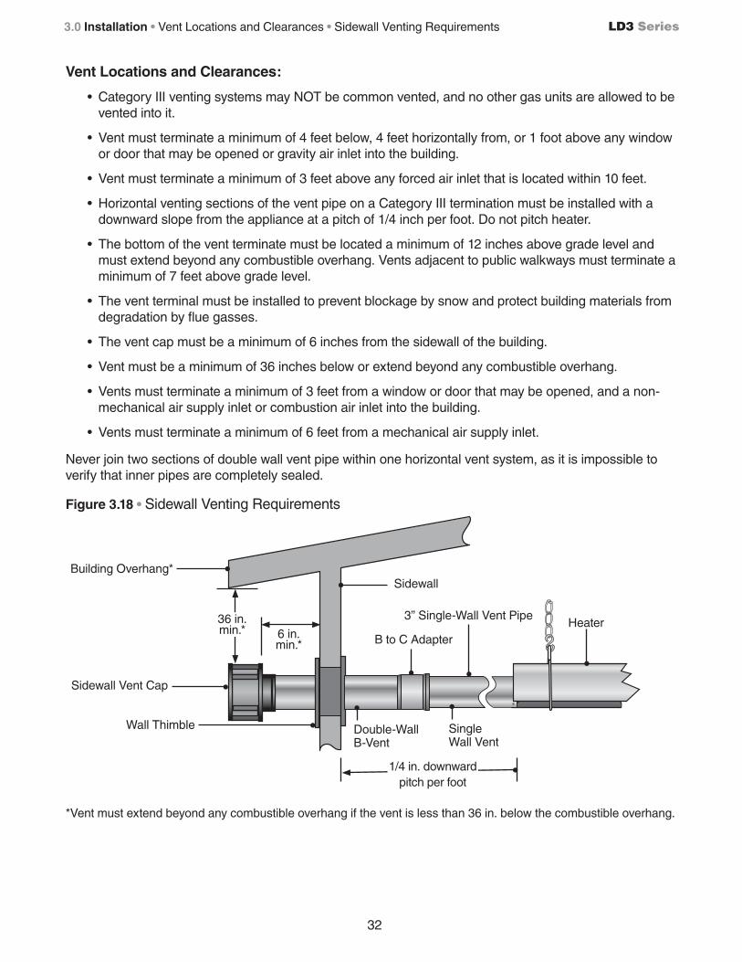
Vent Locations and Clearances:
• Category III venting systems may NOT be common vented, and no other gas units are allowed to be vented into it.
• Vent must terminate a minimum of 4 feet below, 4 feet horizontally from, or 1 foot above any window or door that may be opened or gravity air inlet into the building.
• Vent must terminate a minimum of 3 feet above any forced air inlet that is located within 10 feet.
• Horizontal venting sections of the vent pipe on a Category III termination must be installed with a downward slope from the appliance at a pitch of 1/4 inch per foot. Do not pitch heater.
• The bottom of the vent terminate must be located a minimum of 12 inches above grade level and must extend beyond any combustible overhang. Vents adjacent to public walkways must terminate a minimum of 7 feet above grade level.
• The vent terminal must be installed to prevent blockage by snow and protect building materials from degradation by flue gasses.
• The vent cap must be a minimum of 6 inches from the sidewall of the building.
• Vent must be a minimum of 36 inches below or extend beyond any combustible overhang.
• Vents must terminate a minimum of 3 feet from a window or door that may be opened, and a non-mechanical air supply inlet or combustion air inlet into the building.
• Vents must terminate a minimum of 6 feet from a mechanical air supply inlet.
Never join two sections of double wall vent pipe within one horizontal vent system, as it is impossible to verify that inner pipes are completely sealed.
Figure 3.18 • Sidewall Venting Requirements
*Vent must extend beyond any combustible overhang if the vent is less than 36 in. below the combustible overhang.
Building Overhang*Sidewall
Double-Wall B-Vent
Single Wall Vent
Wall Thimble
Sidewall Vent Cap
6 in. min.* B to C Adapter
Heater
1/4 in. downwardpitch per foot
36 in. min.*
3” Single-Wall Vent Pipe

33
LD3 Series 3.0 Installation • Common Venting (Category I) • Common Rooftop Venting
Common Venting (Category I)
The common vent system and all attached appliances must be Category I.
The vent connector should be routed in the most direct route from the units to the common vent.
Where two or more vent connectors enter a common gas vent or chimney flue, the smaller connector shall enter at the highest level consistent with the available head room or clearance to combustible material.
Restrictions within the common vent such as elbows should be minimized. Each elbow installed within the common portion of the vent carrying system reduces the maximum common vent capacity by 10%. Refer to NFPA 54 IFEC tables 11.2 and 11.3 for capacity.
The vent connector capacities allow for the use of two 90° directional changes. For each additional required elbow, the vent connector capacity is reduced by 10%.
The common vent cross sectional area must be equal to or greater than the largest vent connector cross sectional area.
Figure 3.19 • Common Rooftop Venting - Side View
**Consult the NFPA ANSI Z223.1 Gas Vent Termination criteria if roof pitch exceeds 9:12.
Rooftop Vent Cap
Roof
Dual Exhaust Assembly
Heater
Firestop Spacer
Double-Wall B-Vent
24 in. Min.**
Heater
3” Single-Wall Vent Pipe

34
LD3 Series
Combustion Air Requirements
Combustion air may be supplied to the heater by indoor or outdoor means. Follow these guidelines and all applicable codes for all models prior to installing the combustion air duct work. Local codes may vary. In the absence of local codes, refer and comply with the National Fuel Code ANSI Z223.1 (NFPA 54) latest edition or the National Standards of Canada.
This unit comes standard equipped for connection of supplied outdoor air for combustion. It is designed for outside air to be brought into the appliance from combustion intake ducts, and is referred to as a “Separated Combustion” appliance.
This heater must operate as a separated combustion system if any of the following criteria apply:
• Chemicals such as chlorinated or fluorinated hydrocarbons (typical sources are refrigerants, solvents, adhesives, degreasers, paints, paint removers, lubricants, pesticides, etc.) are present in the atmosphere.
• High humidity.
• Contaminants such as sawdust, welding smoke, etc.
• Negative building pressure.
• Unusually tight construction where the air infiltration rate is less than 0.40 air changes per hour.
If your application does not meet any of these criteria, then room air may be used as supplying combustion air to the heater. Refer to ‘Combustion Air Supply - Room Air’ on page 33 for details on how to utilize room air for combustion.
Sufficient combustion air must be supplied to the appliance at all times. Lack of combustion air may result in property damage, serious injury or death.
WARNING!
3.0 Installation • Combustion Air Requirements
Roof
Roof Intake Cap
18 in. minimum 6” pipe
Air Inlet Connection (Flexible boot and band clamps are recommended)
Air Inlet Connection
Burner Control Box
Burner Control Box
4” intake pipe4” intake pipe
Figure 3.20 • Vertical Outside Air Supply for Common Intake • Side View
NOTE: Common intake heaters must share the same thermostat.

35
LD3 Series
Separated Combustion Systems
All LD3 Series heaters come with a factory-installed combustion air adapter for attaching air intake ducts to the heater. Attach the air intake duct material to the adapter with three (3) non-corrosive sheet metal screws. If necessary, drill pilot holes prior to attaching the air intake ducts. The diameter of the intake ducts must not be smaller than the factory installed adapter.
When operating this unit as a separated combustion heater system, combustion air must be supplied to the heater by outdoor means through the factory installed vent connector. The combustion air intake duct may terminate horizontally through a sidewall or vertically through the roof. Ideally, the intake should terminate within the same pressure zone as the venting terminates, which should minimize the effects of wind.
All Separated Combustion systems must comply with the following items:
• Air intake ducts must be of galvanized steel or an equivalent corrosion-resistant material.
• Do not exceed a length of 20 feet.
• Do not exceed more than two (2) 90° directional changes (elbows) in the system.
• Seal all joints with metallic tape or silicone sealant. Wrap the tape two full turns around the vent pipe.
• Slope air intake pipe ¼ inch per foot upward or downward away from the unit.
• Do not draw air from attic space.
• Do not draw fresh air from the remaining space around a chimney liner, gas vent, special gas vent, or plastic piping installed within masonry, metal, or factory built chimney.
• Combustion air ducts may be insulated if they pass through an unconditioned space.
• A factory approved sidewall intake cap must be used when terminating the combustion air ducts horizontally through the sidewall.
• When combustion air ducts terminate vertically through the roof, a minimum of 18 inches above the roof grade must be maintained.
• Separate the air intake duct from vent pipe a minimum of 4 feet. Also, place vent pipe higher than adjacent air intake duct.
• Air intake duct must terminate a minimum of 3 feet below any forced air vent discharge that is located within 10 feet.
• The bottom of the air intake duct termination must be located a minimum of 12 inches above grade level. Air intake ducts that terminate adjacent to public walkways must be installed a minimum of 7 feet above grade level.
• The air intake duct must be installed to prevent blockage by snow, debris, or other possible obstructions.
3.0 Installation • Separated Combustion Systems

36
LD3 Series3.0 Installation • Separated Combustion Systems
Figure 3.21 • Outside Combustion Air Vertical Intake - Side View
Roof
Listed Exhaust Cap
18 in. Min.
Combustion Air Intake Cap
BurnerControl Box
X3 ft. Min.
(If X if less than 10 ft.)
Storm CollarListed Flashing
Cleanout Tee
Figure 3.22 • Outside Combustion Air Sidewall Intake - Side View
Burner Control Box
Air Inlet Connection (Flexible boot and band clamps are recommended)
Combustion Air Intake Cap
Vent Termination Support Brackets
1/4 in. pitch per foot (upward or downward)
6 in. Min.
Listed Wall Thimble
4” Pipe
Air Inlet Connection (Flexible boot and band clamps are recommended)

37
LD3 Series
When using an unvented configuration (commercial & industrial use only), consider the following:
• A factory vent cap/diffuser (P/N: WVE-3) must be used.
• Where unvented heaters are used, natural or mechanical means must be provided to supply and exhaust a minimum of 4 cfm/1000 Btu/h input of installed heaters.
NOTE: Gravity or mechanical means may be used to accomplish the air displacement. Local codes may require that the mechanical exhaust system be interlocked with the electrical supply line to the heaters, enabling both to function simultaneously.
• The minimum clearance between the air intake and the exhaust terminal is 4 ft.
NOTE: When installing in a U-tube configuration, use extra caution to separate vent gases from heater intake.
• Exhaust openings for removing the flue products must be located above the level of the heater(s).
Figure 3.23 • Minimum End Clearances
Combustion Air Supply - Room Air
Combustion air may be supplied to the heater by indoor or outdoor means.
If using combustion air from indoors, the required volume of the space must be a minimum of 50 ft3 per 1000 Btu/hr unless the building is of unusually tight construction. If the building is of unusually tight construction with air infiltration rates of less than 0.40 air changes per hour, outside combustion air is typically needed unless the sheer size of the building allows otherwise. Contact the factory for further determination of air infiltration rates.
12 in. Min.
unvented heaters
12 in. Min.
All heaters
WARNING!
This appliance must be vented in residential installations. Unvented tube heaters in residential spaces may result in property damage, serious injury or death. Use unvented operation in commercial and industrial installations with proper ventilation rates only.
Optional Unvented Operation
3.0 Installation • Optional Unvented Operation • Combustion Air Requirements

38
LD3 Series3.0 Installation • Combustion Air Requirements • Gas Supply
WARNING!
Improperly connected gas lines may result in serious injury and death, explosion, poisonous fumes, toxic gases or asphyxiation. Connect gas lines in accordance to national, state, provincial and local codes.
Gas pressure to the appliance controls must never exceed 1/2 PSI (14” W.C.). Damage to the controls may result.
Gas lines should be purged of air as described in ANSI Z223.1 (NFPA 54) or CSA-B149.1– latest version. Installation of the piping must also conform with the local building codes, or in the absence of local codes, with the latest edition of the National Fuel Gas Code (NFPA 54). In Canada, installation must be in accordance with CSA-B149.1
CAUTION!
Non-contaminated outside air for combustion must be ducted to the heater if any of the following apply:
• Chemicals such as chlorinated or fluorinated hydrocarbons (typical sources are refrigerants, solvents, adhesives, degreasers, paints, paint removers, lubricants, pesticides, etc.) are present in the atmosphere.
• High humidity.
• Contaminants such as sawdust, welding smoke, etc.
• Negative building pressure.
• Unusually tight construction where there is an air infiltration rate of less than 0.40 per hour.
Gas Supply Installation Instructions
The gas supply to the tube heater must be connected and tested in accordance with national, state, provincial, and local codes along with guidelines in this manual. In the United States refer to the latest edition of the ANSI Z223.1 (NFPA54) Standard and in Canada refer to the latest edition of the CAN/CGA B149.1 Standard.
Supply gas piping to the unit should conform with the local and national requirements for type and volume of gas handled, and pressure drop allowed in the line. Avoid pipe sizes smaller than 1/2”.
NOTICEThe total input to the appliance must fall within +/- 5% of the rated input as indicated on the rating plate. Otherwise the heat exchanger may prematurely fail.
The installation must conform with local building codes or, in the absence of such codes, the National Fuel Code (NFPA 54) and in conjunction with ANSI Z21.24/CSA 6.10 “Connectors for Gas Appliances”.

39
LD3 Series 3.0 Installation • Combustion Air Requirements • Gas Supply
IMPORTANT! The heating system will expand and contract during operation. Allowances for expansion must be made between the connection to the heater and the gas supply. A flexible gas connection of approved type is required. Flexible Type 1 rubber gas connectors installed in one plane, and without sharp bends, kinks or twists is recommended.
IMPORTANT! Before connecting the gas supply to the burner control box:
• Verify that the heater’s gas type (as listed on the rating plate) matches that of your application and the installation complies with national and local codes and requirements of the local gas company.
• Unless otherwise noted on the rating plate, this infrared heater is designed and orificed to operate on standard BTU gas. Contact the factory if utilizing non-standard BTU gas.
• Check that the gas piping and service has the capacity to handle the total gas consumption of all heaters being installed, as well as any other gas appliances being connected to the supply line.
• Check that the main gas supply line is of proper diameter to supply the required fuel pressures.
• If utilizing used pipe, verify that its condition is clean and comparable to a new pipe. Test all gas supply lines in accordance with local codes.
To connect the gas:
The LD3 Series heater is equipped to connect to the corrugated stainless steel tube (CSST) Type 1 rubber gas connector (Included). Do not connect the main gas line directly to the heaters gas inlet without the use of the flexible connector. All piping must be installed in accordance with the requirements outlined in the National Fuel Gas Code ANSI/Z223.1 (latest edition) or CSA-B149.1 and B149.2. Support all gas piping with pipe hangers, metal strapping, or other suitable material. Do not rely on the heater to support the gas pipe.
When connecting piping to the unit, the use of a thread joint compound is required. The thread compound (pipe dope) shall be resistant to the action of liquefied petroleum gas or any other chemical constituents of the gas to be conducted through piping. Use of Teflon® tape is not permitted.
Install ground joint union with a brass seat and a manual shut-off valve adjacent to the unit for emergency shut-off and easy servicing of controls. A 1/8” NPT plugged tap that is accessible for a test gauge connection is also recommended, as illustrated in Figure 3.26.
A sediment trap must be installed in the supply line in the lowest spot prior to connecting to the heater. The trap length shall be at least three inches long. Ideally, the trap would be installed as close as possible to the shut-off, as shown in Figure 3.26.
WARNING!
Failure to install, operate or service this appliance in the approved manner may result in property damage, injury or death. Only trained, qualified gas installation and service personnel may install or service this equipment.
WARNING!Always use two (2) opposing wrenches to tighten mating pipe connections to prevent excessive torque on the gas valve and manifold pipe. Excessive torque can damage the valve and/or misalign the orifice, resulting in fire, explosion, serious injury or death.

40
LD3 Series3.0 Installation • Gas Supply
CAUTION!When using a Type 1 rubber flexible gas connector, do not attach the connector nuts directly to the gas pipe supply. Connector nuts must be installed to an approved adapter.
Connect the main gas supply line with an approved flexible connector or, if the authority having jurisdiction requires rigid piping, the use of approved swing joints may be used. If swing joints are utilized, the heater must be allowed to freely expand and contract without causing undue stress on the gas pipe.
The heater shall not be connected to the building piping system with rigid pipe or semi-rigid metallic tubing, including copper. When using such material, an intermediate connection device that allows for the heater expansion must be used.
The gas outlet must be in the same room as the appliance is installed, and must be accessible. It may not be concealed within or run through any wall, floor or partition. When installing the heater in a corrosive environment (or near corrosive substances), use a gas connector suitable for the environment. Do not use the gas piping to electrically ground the heater.
Installation of the Gas Line to the Heater
1 Install a sediment trap / drip leg in the supply line at the lowest spot prior to the gas ball valve. The trap length shall be at least three inches long. Ideally, the trap would be installed as close as possible to the shut off.
2 Install manual shut off ball valve with optional 1/8” NPT Test connection towards the supply line. The manual shut off ball valve must be located within 6 feet of the appliance’s service access door.
3 Install the 5/8 inch flare to ½” NPT adapter piece downstream of the gas valve as shown in Figure 3.26. This piece is typically included with the flexible gas connector, loosely installed on one of the flare nuts. NOTE: Keep flare surfaces clean and free of sealing compounds. Only the pipe threads require sealing compounds.
4 Form the Type 1 rubber flexible gas connector into a smooth U-shape, allowing approximately 14 inches between the flexible connector’s end nuts (see Figure 3.26). The connector must reach from the gas supply to the appliance without stretching, kinking, or twisting.
5 Attach the flexible connector to the 5/8” flare adapter on the gas line and the other end to the 5/8” flare on the heaters inlet pipe. DO NOT connect the connector flare nuts directly to pipe threads. Use only the adapters provided. DO NOT kink, twist or over-torque the connector when installing.
Figure 3.24 • Installation 1/2” Gas Connection
7”-14”18cm-36cm 9”-14”
23cm-36cm
9”-14”23cm-36cm
Correct Method
Wrong Method
Side View Front View
Side View Front View

41
LD3 Series
Refer to Chart 3.7 for natural gas and Chart 3.8 for propane to determine the cubic feet per hour (CFH) required for the type of gas and size of unit to be installed. To determine the proper pipe diameter, use the CFH value and the length of pipe necessary from Chart 3.9. In the case where several units are serviced by the same main gas line, the total capacity (CFH) and length of main must be adequate to service all appliances downstream of this main.
Chart 3.7 • Natural Gas Consumption
* Assumes an average heating value of 1050 BTU/SCF and a Specific Gravity of 0.60.
Chart 3.8 • Propane Gas Consumption
* Assumes an average heating value of 2500 BTU/SCF and a Specific Gravity of 1.53.
Chart 3.9 allows for a 0.3 inch W.C. pressure drop in the supply pressure from the building main to the inlet of the unit. Refer to the chart for the appropriate range of inlet pressures for each gas type. When sizing the inlet gas pipe diameter, make sure that the unit supply pressure can be met after the 0.3 inch W.C. pressure drop has been subtracted from the main pressure. If the 0.3 inch W.C. pressure drop is too high, refer to NFPA 54 or the Gas Engineer’s Handbook for other gas pipe capacities.
3.0 Installation • Gas Supply
Figure 3.25 • Gas Connection (Flexible Gas Connection shown) • End View
Figure 3.26 • Gas Connection (Flexible Gas Connection shown) • Side View
ModelInput
(High/Low)Manifold Pressure
Minimum Inlet Pressure
Gas Consumption
(CFH) Orifice Size
LD3-(15,20)-4040,000 3.5” W.C.
5.0” W.C.38.1
31 DMS28,000 2.2” W.C. 26.7
LD3-(15,20,30)-5050,000 3.5” W.C.
5.0” W.C.47.6
29 DMS35,000 2.2” W.C. 33.3
ModelInput
(High/Low)Manifold Pressure
Minimum Inlet
Pressure
Gas Consumption*
(CFH)Gallons
per Hour* Orifice Size
LD3-(15,20)-4040,000 10.0” W.C.
11.0” W.C.16.0 0.44
1.90 mm28,000 5.0” W.C. 11.2 0.31
LD3-(15,20,30)-5050,000 10.0” W.C.
11.0” W.C.20.0 0.55
2.15 mm35,000 5.0” W.C. 14.0 0.38
7”-14”
Type 1 Gas Hose Connector
5/8” O.D. Flare to 1/2” NPT Adapter
3 inch minimumDrip Leg/Sediment Trap
Heater Movement
Burner Control Box Side View
Ball Valve w/ 1/8” NPT Inlet Tap
5/8” O.D. Flare to 1/2” NPT AdapterBall Valve w/ 1/8” NPT Inlet Tap
Burner Control Box End View
1/2” Elbow 1/2” Elbow

42
LD3 Series
Leak Testing
Use a soap solution or equivalent for leak testing. Leak testing solution must be non-corrosive, and be rinsed off immediately after the leak test. Never test for leak with an open flame. Failure to comply could result in personal injury, property damage or death.
Always leak test final gas assembly for gas leaks according to the procedures outlined in NFPA 54 and all local codes and/or Standards.
For leak testing on pressures below 1/2 PSIBefore leak testing, close the field installed manual shut off valve shown on Figure 3.26 on the supply line to isolate the gas valve from the pressure. NOTE: All factory installed gas connections have passed an approved leak test.
For leak testing on pressures above 1/2 PSIWhen leak testing with pressures above 1/2 PSI (14 inches W.C.), the unit must be isolated from the supply pipe. Close the field installed manual shut off valve, disconnect the supply line to the unit, and temporarily cap the supply line for testing purposes.
WARNING!
Gas pressures to the appliance controls must never exceed 14 inches W.C. (1/2 PSI). Supply pressures greater than 14” W.C. can damage the controls, resulting in personal injury, property damage, or death.
WARNING!
Testing for gas leaks with an open flame or other sources of ignition may lead to a fire or explosion and cause serious injury or death. Test in accordance with NFPA or local codes.
3.0 Installation • Leak Testing
Chart 3.9 • Maximum capacity for Schedule 40 Metallic pipe, in CFH
Pipe Length
1/2” 3/4” 1” 1-1/4” 1-1/2” 2”
Nat L.P. Nat L.P. Nat L.P. Nat L.P. Nat L.P. Nat L.P. 10 feet 132 86 278 182 520 340 1050 686 1600 1046 3050 1993
20 feet 92 60 190 124 350 229 730 477 1100 719 2100 1373
30 feet 73 48 152 99 285 186 590 386 890 582 1650 1078
40 feet 63 41 130 85 245 160 500 327 760 497 1450 948
50 feet 56 37 115 75 215 141 440 288 670 438 1270 830
60 feet 50 33 105 69 195 127 400 261 610 399 1150 752
70 feet 46 30 96 63 180 118 370 242 560 366 1050 686
80 feet 43 28 90 59 170 111 350 229 530 346 990 647
90 feet 40 26 84 55 160 105 320 209 490 320 930 608
100 feet 38 25 79 52 150 98 305 199 460 301 870 569
125 feet 34 22 72 47 130 85 275 180 410 268 780 510
150 feet 31 20 64 42 120 78 250 163 380 248 710 464
175 feet 28 18 59 39 110 72 225 147 350 229 650 425
200 feet 26 17 55 36 100 65 210 137 320 209 610 399
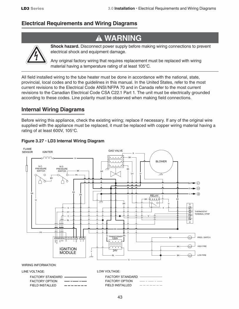
43
LD3 Series
Electrical Requirements and Wiring Diagrams
All field installed wiring to the tube heater must be done in accordance with the national, state, provincial, local codes and to the guidelines in this manual. In the United States, refer to the most current revisions to the Electrical Code ANSI/NFPA 70 and in Canada refer to the most current revisions to the Canadian Electrical Code CSA C22.1 Part 1. The unit must be electrically grounded according to these codes. Line polarity must be observed when making field connections.
Internal Wiring Diagrams
Before wiring this appliance, check the existing wiring; replace if necessary. If any of the original wire supplied with the appliance must be replaced, it must be replaced with copper wiring material having a rating of at least 600V, 105°C.
Figure 3.27 • LD3 Internal Wiring Diagram
3.0 Installation • Electrical Requirements and Wiring Diagrams
WARNING!Shock hazard. Disconnect power supply before making wiring connections to prevent electrical shock and equipment damage.
Any original factory wiring that requires replacement must be replaced with wiring material having a temperature rating of at least 105°C.

44
LD3 Series3.0 Installation • Field Wiring Supply Voltage • Thermostat Connection
Field Wiring Supply Voltage
Before proceeding with electrical connections, ensure that the supply voltage, frequency, phase and current capacity meet the requirements specified on the rating plate. A dedicated line voltage supply with properly sized wire should run directly from the main electrical panel to the heater. The power to the unit must be protected with a circuit breaker appropriate for the load. The unit must be electrically grounded in accordance with local codes, or in their absence, with the latest edition of the National Electrical Code, ANSI / NFPA 70 and/or the Canadian Electrical Code CSA C22.1, latest edition.
The heater comes equipped with a supply cord to connect the main power supply. It is located at the rear of the heater’s burner box, and utilizes a grounding prong. This plug must be connected into an appropriate outlet receptacle that is properly installed and grounded in accordance to local codes and ordinances.
The grounding receptacle must be installed within 5 feet of the heater’s service panel, and located in the space occupied by the appliance. When plugging in the heater, make sure the supply cord is protected from damage, and keep all cords away from the heater’s surfaces and out of the clearance to combustible zones (see page 9). When routing the electrical supply for the unit, ensure that it does not interfere or obstruct the heater’s service panel.
Thermostat Connection
NOTE: Different thermostats operate according to their particular features. Refer to the thermostat’s specifications for details.
Prior to connecting the thermostat wire to the heater, check to make sure the wires will be long enough to allow for the heater to freely expand and contract without causing undue strain on the wires or terminal. Use 18 gauge wire (or larger) that is suitable for a NEC Class 2 rating for thermostat connections.
Each LD3 Series heater requires a two-stage thermostat rated for 24VAC to operate. The heater comes standard with a terminal strip for making the thermostatic connection, located on the back panel.
The power supply to the heater must be within +/- 5% of the voltage rating as indicated on the rating plate of the appliance. If input power does not meet these specifications, contact your utility company.
CAUTION!
WARNING!
Electric Shock Hazard
Do not force the three-prong plug into the grounded outlet, modify the plug, or use an adapter. Never operate this appliance if the cord or plug is damaged.

45
LD3 Series 3.0 Installation • Thermostat Connection
The thermostat terminal designations are as follows:
R: 24VAC PowerW1: Call for Heat - Low FireW2: Call for Heat - High FireC: Common for 24VAC Power (if required for thermostat power)
24VAC is supplied from an internal 40VA transformer. DO NOT supply 24 Volts to the terminal strip.
Figure 3.27 • Single Two-Stage Heater, Single Thermostat Connection
Controlling Multiple Heaters with a Single Control Device
When multiple heaters are operated by the same control device (for example, common vented heaters), an external relay kit (Part #ERK) must be utilized per heater. This allows the heater’s 24V supply voltage to be isolated from the external control voltage of the thermostats. The ERK is to be installed on or near the heater. Follow the instructions that accompany the accessory for more information and wiring diagrams.
Figure 3.28 • Multiple Heaters, Single Thermostat Connection with External Relay Kit
Thermostat Location
The location of the thermostat should be determined by the desired heating requirements and be mounted on an inside wall five (5) feet above the finished floor. Locate the thermostat in a conspicuous location, away from where it could be influenced by heat from the unit or other sources, as this may cause the unit to short cycle. Care should be given to locate the thermostat away from drafts or frequently opened doors. To prevent drafts inside the wall from affecting the thermostat’s performance, plug hole for the wire with insulation or suitable caulk. For further information, see the accompanying instructions with the thermostat.
C
R
W1
W2
Two-StageThermostat
OPTIONAL 24V COMMONCHECK THERMOSTAT INSTRUCTIONS TO SEE IF NEEDED.
RELAY BOX
(1 PER HEATER)
W2
W1
R
C
TRANSFORMER
L1
L2
P/N: ERK
C W1 W2
RELAY BOX
(1 PER HEATER)P/N: ERK
C W1 W2
RELAY BOX
(1 PER HEATER)P/N: ERK
C W1 W2
NOTE: W2 NOT USED ON SINGLE STAGE SCENARIOS
HEATER TERMINAL
HEATER TERMINAL
HEATER TERMINALTHERMOSTAT
OPTIONAL 24V COMMONCHECK THERMOSTAT INSTRUCTIONS TO SEE IF NEEDED
24V
120V
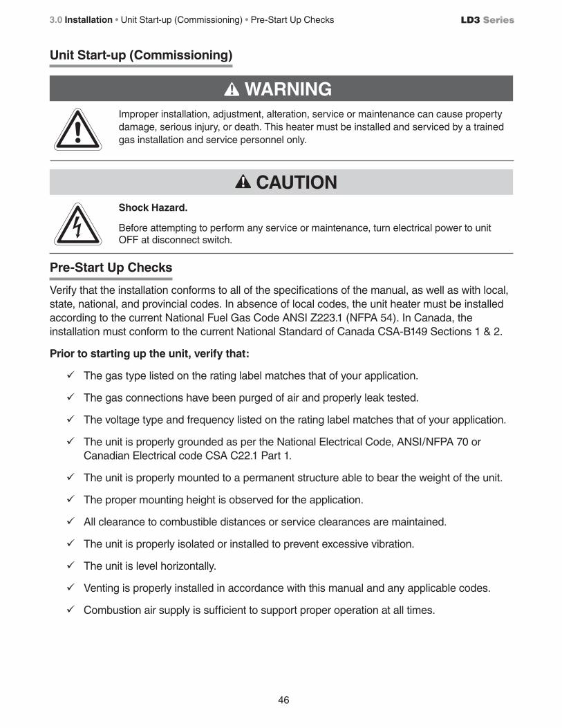
46
LD3 Series3.0 Installation • Unit Start-up (Commissioning) • Pre-Start Up Checks
Unit Start-up (Commissioning)
Pre-Start Up Checks
Verify that the installation conforms to all of the specifications of the manual, as well as with local, state, national, and provincial codes. In absence of local codes, the unit heater must be installed according to the current National Fuel Gas Code ANSI Z223.1 (NFPA 54). In Canada, the installation must conform to the current National Standard of Canada CSA-B149 Sections 1 & 2.
Prior to starting up the unit, verify that:
9 The gas type listed on the rating label matches that of your application.
9 The gas connections have been purged of air and properly leak tested.
9 The voltage type and frequency listed on the rating label matches that of your application.
9 The unit is properly grounded as per the National Electrical Code, ANSI/NFPA 70 or Canadian Electrical code CSA C22.1 Part 1.
9 The unit is properly mounted to a permanent structure able to bear the weight of the unit.
9 The proper mounting height is observed for the application.
9 All clearance to combustible distances or service clearances are maintained.
9 The unit is properly isolated or installed to prevent excessive vibration.
9 The unit is level horizontally.
9 Venting is properly installed in accordance with this manual and any applicable codes.
9 Combustion air supply is sufficient to support proper operation at all times.
WARNING!
Improper installation, adjustment, alteration, service or maintenance can cause property damage, serious injury, or death. This heater must be installed and serviced by a trained gas installation and service personnel only.
Shock Hazard.
Before attempting to perform any service or maintenance, turn electrical power to unit OFF at disconnect switch.
CAUTION!

47
LD3 Series
Verify Proper Inlet Pressure
Before starting up the unit, smell all around the unit heater for gas. Be sure to smell next to the floor because some gas is heavier than air and will settle on the floor.
When turning the gas shut off valve, only use your hand. Never use tools to turn the knobs, as it may damage the valve resulting in a fire or explosion. If the knob is stuck, do not try to repair it, contact a qualified service technician or your local gas company.
To verify the proper inlet pressures, follow the following steps:
1 Turn off the gas supply at the manual gas shut off valve.
2 Remove the inlet pressure tap plug on the gas control valve (see Figure 3.29).
3 Install a 1/8 inch NPT hose connector and connect the pressure gauge tube.
4 Turn on the gas supply at the manual gas shut off valve.
5 Turn on the electrical power to the heater.
6 To light the burner, set the room thermostat to a point above room temperature.
NOTE: This heater is equipped with an ignition device, which automatically lights the burner. This heater cannot be lighted manually. Do not try to light the burner by hand.
Verify minimum inlet gas supply pressure:
7 Turn on all other gas appliances that are on the same supply line. If the other gas appliances have multiple inputs, set it to the maximum rating.
8 Observe the pressure rating on the pressure gauge.
The minimum inlet gas supply pressure for:
• Natural gas is 5.0 inches W.C.
• Propane gas is 11.0 inches W.C.
Verify maximum inlet gas supply pressure:
9 Turn off all other gas appliances on the same supply line.
10 Observe the pressure reading on the pressure gauge.
The maximum inlet gas supply pressure for:
• Natural gas is 14.0 inches W.C.
• Propane gas is 14.0 inches W.C.
IMPORTANT: If the inlet gas supply pressure is not within the minimum and maximum range as shown on the rating plate, contact your gas supplier.
Removing pressure gauge from inlet port on gas valve.
Set thermostat or other control device to the lowest set point.
11 After heater has completed the post-purge cycle, turn off the electrical power to the heater.
12 Turn off the gas supply at the manual gas shut off valve.
13 Remove the pressure gauge tube and the 1/8 inch NPT hose connector.
3.0 Installation • Verify Proper Inlet Pressure

48
LD3 Series3.0 Installation • Verifying Manifold Pressure
14 Replace the inlet pressure tap plug on the gas control valve.
15 Leak check the re-installed pressure tap plug using a soap solution or equivalent method as described in ANSI Z223.1 (NFPA 54).
Figure 3.29 • Gas Valve Shown in OFF Position
Verify Manifold Pressure
Before starting up the unit, smell all around the unit heater for gas. Be sure to smell next to the floor because some gas is heavier than air and will settle on the floor.
When turning the gas shut off valve, only use your hand. Never use tools to turn the knobs, as it may damage the valve resulting in a fire or explosion. If the knob is stuck, do not try to repair it, contact a qualified service technician or your local gas company.
To verify the proper manifold pressure, follow the following steps:
1 Turn off the gas valve with the switch located on the valve body (see Figure 3.29).
2 Remove the manifold pressure tap plug on the gas control valve(see Figure 3.29).
3 Connect the pressure gauge tube and manometer.
4 Turn on the gas valve with the switch located on the valve body.
5 Turn on the electrical power to the heater.
6 To light the main burner, set the room thermostat to a point above room temperature.
NOTE: This heater is equipped with an ignition device, which automatically lights the burner. This heater cannot be lighted manually. Do not try to light the burner by hand.
Verify manifold pressure:
7 After the unit has successfully ignited, wait five minutes prior to taking any readings. The heater must be in a steady state of operation prior to taking a manifold pressure reading.
8 While waiting for the unit to stabilize, observe the characteristics of the flame. The flame should be stable and should not lift from the burner. The burner color should be light blue, and not create excessive noise.
Inlet Pressure Port
Manifold Pressure Port
On/Off Switch
High Fire Manifold Pressure Adjustment Screw
Low Fire Manifold Pressure Adjustment Screw

49
LD3 Series
9 After five minutes, observe the pressure rating on the pressure gauge.
The target manifold gas supply pressure for:
• Natural gas is 3.5 inches W.C.
• Propane gas is 10.0 inches W.C.
NOTE: Manifold pressure of the heater is pre-set at the factory. No adjustment should be necessary.
During the verification process, a tolerance of +/- 5% of the full scale is acceptable due to varying atmospheric conditions.
If manifold pressure is outside of this tolerance, then an adjustment may be necessary.
Removing pressure gauge from manifold port on gas valve:10 Set thermostat or other control device to the lowest set point.
11 After heater has completed the post-purge cycle, turn off the electrical power to the heater.
12 Turn off the gas valve with the switch located on the valve body (see Figure 3.29).
13 Remove the pressure gauge tube and the manometer.
14 Replace the manifold pressure tap plug on the gas control valve.
15 Leak check the re-installed pressure tap plug using a soap solution or equivalent method as described in ANSI Z223.1 (NFPA 54).
Prior to leaving the Job Site
Prior to leaving the job site, verify that:
9 Service access door is properly secured to the unit.
9 The heater is clear of any objects that would interfere with the proper air circulation or that violate the listed clearance to combustibles.
9 Manual gas shut off is ON.
9 Electrical power is ON.
9 Thermostat is set to desired temperature.
9 Properly dispose of all packaging materials.
9 Check to be sure you have all of your tools.
9 Leave the Installation, Operation, Maintenance and Parts Manual with the owner or end user.
Chart 3.10 • Manifold Pressure
Pressure Equivalents: 1 Inch W.C. equals .058 oz/sq. in. equals 2.49 mbar.
Type of GasRequired Manifold
PressureMinimum Inlet
PressureMaximum Inlet
Pressure
Natural 3.5 Inches W.C. 5.0 Inches W.C. 14.0 Inches W.C.
Propane 10.0 Inches W.C. 11.0 Inches W.C. 14.0 Inches W.C.
3.0 Installation • Prior to Leaving the Job Site

50
LD3 Series
High Altitude Operation
High altitude operation of this tube heater is approved, without modification, for elevations up to 6,000 feet (1,829 m) above MSL (sea level) in the United States. If the heater is being installed at an elevation above 6,000 ft, the input rate will have to be de-rated to ensure proper operation. The deration is achieved by a gas orifice change. Contact the factory for installations above these elevations.
WARNING!
Explosion hazard. This heater must be converted by a trained gas installation and service personnel only. Failure to comply could result in personal injury, asphyxiation, death, and fire or property damage.
3.0 Installation • High Altitude Operation

51
LD3 Series 4.0 Operation • Operating Instructions
4.0 Operation
WARNING!
BEFORE OPERATING, smell all around the appliance area for gas. Be sure to smell next to the floor because some gas is heavier than air and will settle to the floor. Refer to page 1 “If you smell gas” and on safety label affixed to the heater.
Do not use this appliance if any part has been under water. Immediately call a qualified service technician to inspect the appliance and to replace any part of the control system and any gas control which has been under water.
Operating Instructions
This appliance does not have a pilot ignition. It is equipped with an ignition device which
automatically lights the burner. Do not attempt to light the system by hand.
Lighting Procedures:
1 STOP! Read the safety information above.
2 Set the thermostat to the lowest setting.
3 Turn OFF all electrical power to the appliance.
4 Turn manual shutoff clockwise to “OFF”.
5 Wait five (5) minutes to clear out any gas. If you smell gas STOP! Follow the safety information found on page 1 “If you smell gas” and on safety label affixed to the heater. If you do not smell gas, proceed to step 6.
6 Turn manual shutoff knob counterclockwise to “ON”.
7 Turn ON all electrical power to the appliance.
8 Set thermostat to desired setting.
9 If the appliance will not operate, follow instructions below to turn OFF gas to the appliance and call your service technician or gas supplier.
Shutdown Procedures:
1 Set the thermostat to the lowest setting.
2 Turn OFF all electrical power to the appliance if service is to be performed.
3 Turn manual shutoff knob clockwise to “OFF”. Do not force.
WARNING!
Use only your hand to turn the manual shutoff. Never use tools. If the
knob will not turn by hand, don’t try to repair it; call a qualified technician.
Force or attempted repair may result in a fire or explosion.

52
LD3 Series
Sequence of Operation
Standby: The ignition module (circuit board)continually checks for internal faults, circuit integrity and relay contact positioning.
Starting Circuit: Upon a call for heat, the control verifies that the burner and exhaust pressure switches are in their proper positions. The control energizes the fan. Once operational static pressure is achieved, the burner pressure switch will close initiating the ignition sequence. The hot surface igniter is powered and the gas valve opens after 45 seconds. If the flame is not sensed, the heater will attempt to re-ignite for a total of 3 trials for ignition before proceeding to soft lockout.
Low Fire Running Circuit: After ignition, the flame rod monitors burner flame. If sense of flame is lost, the control closes the gas valve within one second and a new trial sequence (identical to the starting sequence) is initiated. If flame sense is not established within 8.5 seconds, the heater will attempt two additional ignition sequences before proceeding to soft lockout. The control can be reset by briefly interrupting the power source.
High Fire Running Circuit: The second stage on the gas valve is powered directly from the second stage of the thermostat. In order for high fire to engage, low fire must be energized as well. The thermostat determines which stage to maintain for the desired comfort level.
Shut Down: When the thermostat is satisfied, the fan will enter a two (2) minute post-purge cycle.
WARNING!This heater must be installed and serviced by trained gas installation and service personnel only.
Do not bypass any safety features or the heater’s built in safety mechanisms will be compromised.
4.0 Operation • Sequence of Operation

53
LD3 Series
Chart 4.1 • LED Fault Code Status
Figure 4.1 • Operational Indicator Lights
Diagnostics
Lockout:The controls will automatically lockout the heater system when an external or system fault occurs. There are two types of lockout:
Soft Lockout: The heater will attempt to light three times. In the event of a failed attempt to light, (gas pressure, valve, no flame sense etc.), the heater will enter a soft lockout period for 30 minutes and then attempt to light three more times before entering hard lockout mode.
Hard Lockout: If proof of flame is not established, a component failure occurs or blockages are evident, the heater will enter hard lockout. If lockout occurs, the control can be reset by briefly interrupting the power source. Refer to Chart 4.1 below for a description of LED codes.
Externally located operational indicator lights are provided to assist in troubleshooting of the heater. Refer to pages 50-53 for additional troubleshooting.
LED CODE FAULT STATUS FAULT CODE DELAY*Initial Flash on power up, then
steady offNormal operation Immediate
Steady on Module failure/Internal fault Immediate
1 flash Ignition failure 32 minutes
2 flashes APS 1 failure 12 minutes
3 flashes APS 2 failure 22 minutes
4 flashesSolenoid valve fault/Leaky valve/
Flame amplifier faultImmediate
No flash on 117V start-up Transformer fault Immediate
*Some LED codes have a time delay before the LED will flash.
Light 3 Indicates High Fire
Operation
Light 1Indicates Pressure
Switch Closes
Operational Indicator Lights
4.0 Operation • Diagnostics
Light 2Indicates Low Fire
Operation

54
LD3 Series5.0 Maintenance • Troubleshooting Guide
Yes
Continued on page 52
5.0 Maintenance
Does the heater have 120 VAC at the main power connection?
Turn on control device for heat.
Does the draft inducer motor
turn on?
Is the pressure switch light on?
Yes
Pressure switch is stuck. Replace
faulty switch.
Does the pressure switch indicator light
turn on?
Yes
Does the igniter warm up and
glow red?
Yes
Does the valve indicator light
turn on?
Yes
Does the gas valve turn on?
Yes
Check for loose wiring or restrictions in the hose
connection to the pressure switch. Are they acceptable?
Is the inlet or outlet of the heater obstructed, or is the vent exceeding the recommended lengths?
No
Remove obstruction or correct vent lengths.
Replace wiring or hose connections.
No
NoNo
Yes
Find source of electrical problem.
Is the igniter physically damaged?
No
Yes
Replace igniter.
No Check voltage at igniter sequence (usually 5 to 15 seconds after call for heat). Is it 120V?
No
Is the inlet or the outlet of the unit plugged or
obstructed?
No
Disconnect igniter and measure the resistance. Is it
between 50-400 Ω?
Yes
Yes Replace circuit board.
NoYes
YesRemove
obstruction.
No
Does the gas valve turn on? Do you see the burner in
the sight glass?No Yes
Gas valve indicator light is burned out.
Replace light.
Check inlet pressure to the heater. Is it within the minimum and maximum
allowable range as per the rating plate?
No
No
YesAre the wires to and from the
gas valve properly connected?
No Adjust inlet pressure.
Yes
No
Correct wiring.
Key
Start Question
ProcessQuestion
CorrectiveAction
No

55
LD3 Series 5.0 Maintenance • Troubleshooting Guide
Bypassing any switch is intended for testing purposes only. Do not leave switch bypassed during normal operation or the heater’s built-in safety mechanisms will be compromised.
* Refer to LED diagnostic Fault Code Chart. Continued on page 53
Is the circuit board sending 120 VAC
to the draft inducer motor?
Check fuse on circuit board and internal controls transformer.
YesIs there 24 VAC across
the ‘R’ and ‘C’ terminals?
Is there 24 VAC across
the ‘W’ and ‘C’ terminals?
Yes
After approximately 10 second of operation, is there
a flash code for Pressure Switch Failure?
No
Replace pressure switch after verifying:
• Heater, blower, and venting are clean and free of obstructions.
• The allowable vent length is not exceeded.
• There is not a negative pressure experienced at the area of intake (e.g., high winds, attic space, tightly sealed building).
No
Repair thermostat or thermostat wiring.
Yes
Remove obstruction.
Is the draft inducer impeller obstructed
or locked up?
Yes
Is the pressure switch stuck in the closed position?
No
The draft inducer motor is faulty and must be replaced.
Replace circuit board.
Monitor the voltage on the gas valve terminals during trial for ignition. Is there 24 VAC present during the
ignition sequence?
Yes
Pressure switch is faulty.
Replace circuit board.
No
NOTICE
Yes
No
Check for loose wiring or restrictions in hose
connections to pressure switch. Are the OK?
No
Replace wiring or hose connections.
Gas valve is faulty. Replace.Yes
Check for flash codes on the circuit board. Replace the ignition module.
No
Yes *After 10-12 seconds of non-operation has passed, is there a flash code for
APS failure (2 or 3 flashes)?
Replace circuit board.No
Yes
No

56
LD3 Series
Does the burner light?
Is the gas supply valve to the heater in the ‘ON’
position?
Were the gas lines purged of air?
Continued from page 50
5.0 Maintenance • Troubleshooting Guide
YesNo Yes
Does the burner stay on?
Yes
Does the heater stay on until
the call for heat ends?
Yes
Do the burners light and then shut off immediately
(within 1-2 seconds)?No
Does the burner stay on for approximately 8-10
seconds and then shut off?No Yes
Turn on gas supply line.
No Purge gas line.
No
Check inlet pressure and limit switches.
Check circuit board for flash codes. Consult factory.
NoThe heater can shut down due to:
• Improper grounding • High winds. • Taking combustion air from the attic. • Dirty environment. • Fluctuating gas pressure. • Pressure switch opening.Yes
Troubleshooting ends.For more information, contact
your local representative or the factory for further assistance.
Yes No

57
LD3 Series 5.0 Maintenance • Troubleshooting Guide
Check to make sure gas pressure is within minimum and maximum inputs, as
indicated on the heater’s rating plate. Is the gas pressure OK?
Is the heater properly grounded? Is the heater’s
polarity correct?
Replace gas valve.Correct problem.
No
Correct problem.
No
On the outside of the control box, is there 24V across the ‘W2’ and ‘C’ connectors on
the terminal strip?
Repair or replace faulty wiring or thermostat. Replace relay board.
No
If heater does not go into high fire mode:
Measure voltage across the ‘HI’ and the ‘C’ connectors on the gas valve.
Is it 24V?
Yes
NoYes
Replace gas valve.
NOTE: To confirm that the heater is not in high fire mode, check manifold pressure.If manifold pressure is 3.3” to 3.5” for natural gas or 9” to 10” for propane, the light is faulty and should be replaced.
When the heater is in low fire mode, manifold pressure is approximately 2.0” to 2.5” for natural gas or 5.0” to 6.5” for propane. If this is the case, the following troubleshooting steps should be followed:
Yes
Replace the appropriate pressure switch after verifying:
• There is continuity across the thermal fuse.• Heater, fan blowers ,squirrel cage, intake
and exhaust are clean and free from dirt and obstructions.
• The 4” air intake pipe does not exceed 20 ft. and/or 2 elbows.
• There is not a negative pressure experienced at the area of air intake (e.g.; high winds, attic space, tightly sealed building).
Continued from page 51
The heater is equipped with two safety pressure switches. The burner switch is a
normally open switch and the exhaust switch is a normally closed switch. Temporarily place jumpers across the terminals of the
exhaust switch (reinstall control box cover). Does the igniter glow red?
NOTE: If normal operation does not continue after bypassing the exhaust switch, consult
factory to troubleshoot the burner switch prior to continuing.
YesNo
With a microampmeter, check DC amperage at flame rod. Is it greater than .07 microamps?
Check to make sure flame sensor
wire is OK and then replace circuit board.
Sensing rod is faulty or flame is weak. Check to make sure heater is operating at proper gas pressure as indicated on heater’s rating plate and then, if needed, replace
sensing rod.
Yes
YesNo
Replace circuit board.

58
LD3 Series5.0 Maintenance • Maintenance Checks & Log
WARNING!
Personal injury or death may result if maintenance is not performed by properly trained gas installer or service personnel. Contact the installing distributor or place of purchase for service. Do not operate heating system if repairs are necessary.
Allow heater to cool prior to servicing.
Disconnect power to heater before servicing.
Use protective glasses when maintaining the heater.
Routine Inspection: At least once per year, the heating system should be inspected and serviced by trained gas installation and service personnel only. This inspection should be performed at the beginning of the heating season to insure that all heater components are in proper working order and that the heating system operates at peak performance. Particular attention should be paid to the following items.
• Clearance to Combustibles: Inspect the area near the unit to be sure there is no combustible material located within the minimum clearance requirements listed in this manual. Under no circumstances should combustible material be located within the clearances specified in this manual. Failure to provide proper clearance could result in personal injury or equipment damage from fire.
• Gas Connection: Inspect the integrity of the gas connection to the heater. Check for leaks, damage, fatigue or corrosion. Do not operate if repairs are necessary and turn off gas supply to the heater. Contact service personnel.
To check gas tightness of the safety shut-off valves, turn off the manual valve upstream of the appliance combination control. Remove the hex head plug on the inlet side of the combination control and connect a manometer to that tapping.
Turn the manual valve on the apply pressure to the combination control. Note the pressure reading on the manometer, then turn the valve off. Any loss of pressure indicates a leak. If leak is detected, use a soap solution to check all threaded connection. If no leak is found, combination control is faulty and must be replaced before putting appliance back in service.
• Blower Motor: Annual oiling of the blower motor with SAE 20 oil will extend bearing life significantly. Ensure that the squirrel cage in the blower is kept clean. If dirt becomes a problem, installation of outside air intake ducts for combustion is recommended.
Check lubrication instructions on motor. If oiling is required, add three or four drop of SAE 20 electric motor oil.
• After three years or 25,000 hour (for light-duty operation).
• Annually after three years or 8,000 hours (for medium-duty operation).
• Annually after one year or 1,500 hours (for heavy-duty operation).
Never over-oil the motor, or premature failure may occur.
NOTICE

59
LD3 Series
• Vent pipe system: Check the outside termination and the connections at the heater. Inspect the vent exhausts for leakage, damage, fatigue, corrosion and obstructions. If dirt becomes a problem, installation of outside air intake ducts for combustion is recommended.
• Combustion air intake system (when applicable): Check for blockage and/or leakage. Check the outside termination and the connection at the heater.
• Heat exchangers: Check the integrity of the heat exchangers. Replace if there are signs of structural failure. Check for corrosion and/or buildup within the tube exchanger passageways.
• Burner: Check for proper ignition, burner flame and flame sense. Flame should extend directly outward from burner without floating or lifting.
• Wiring: Check electrical connections for tightness and/or corrosion. Check wires for damage.
• Gas Connection: Inspect the integrity of the gas connection to the heater. Check for leaks, damage, fatigue or corrosion. Do not operate if repairs are necessary and turn off gas supply to the heater. Contact service personnel.
• Reflectors: To maintain effective infrared heating, always keep both sides of the reflector clean. Maintenance can vary significantly depending on the environment. Dirt and dust can be vacuumed or wiped with a soap and water solution. Use metal polish if the reflectors are severely dirty.
Contact service personnel if repairs are necessary. Do not operate unit.
Maintenance Log
Date Maintenance Performed Replacement Parts Required
5.0 Maintenance • Maintenance Checks & Log

60
LD3 Series5.0 Maintenance • Heater Components and Parts List
Figure 5.1 • Burner Assembly Components
Figure 5.2 • Tube & Reflector Components
21B
1514
1617
383A222A
221
30503012
3011
204
3097
3044
3098A
3008
3002A
3099
76212
1070A5
3062, 3063
826
3001B
30043014
3115
3003A
1325
851B
3252
31D
68B 3010
RH-1
3380
3033F
3096
333
321217
3093
70A 222
85
828
3094A
84
3313023
70
245
205
331
3094A
3140, 3141
10A
3005A
206
3029
3020
1021
1013
3161
1428
13
9
106
1088, 3077, 3081, 3088
21B, 220, 1077
20C/D, 112
26B
105
3076, 3082
105
82, 1078
19B113
579
1077
1079
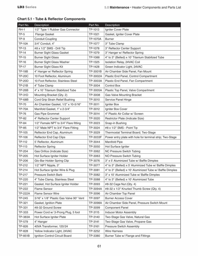
61
LD3 Series
Chart 5.1 • Tube & Reflector Components
Part No. Description Part No. Description
RH-1 1/2” Type 1 Rubber Gas Connector TP-1013 Igniter Cover Plate
TP-5 Flange Gasket TP-1021 Gasket, Igniter Cover Plate
TP-9 Conduit Coupling TP-1070A Burner
TP-10A 3/4” Conduit, 4” TP-1077 3" Tube Clamp
TP-13 #8 x 1/2” SMS - Drill Tip TP-1078 3" Reflector Center Support
TP-14 Burner Sight Glass Gasket TP-1079 3" Hanger w/ Reflector Spring
TP-15 Burner Sight Glass TP-1088 4" to 3" (Belled) x 10' Titanium Stabilized Tube
TP-16 Burner Sight Glass Washer TP-1325 Isolation Relay, 24VAC Coil
TP-17 Burner Sight Glass Kit TP-1428 Green Indicator Light, 24VAC
TP-19B 4” Hanger w/ Reflector Spring TP-3001B Air Chamber Side Panel, Fan Mount
TP-20C 10 Foot Reflector, Aluminum TP-3002A Plastic End Panel, Control Compartment
TP-20D 10 Foot Reflector, Stainless Steel TP-3003A Plastic End Panel, Fan Compartment
TP-21B 4” Tube Clamp TP-3004 Control Box
TP-26B 4” x 10’ Titanium Stabilized Tube TP-3005A Plastic Top Panel, Valve Compartment
TP-31D Mounting Bracket (Qty. 2) TP-3008 Gas Valve Mounting Bracket
TP-68B Cord Grip Strain Relief Bushing TP-3010 Service Panel Hinge
TP-70 Air Chamber Gasket, 1/2” x 10-5/16” TP-3011 Igniter Box
TP-70A Manifold Gasket, 1” x 2-3/4” TP-3012 Igniter Box Cover
TP-76 Gas Pipe Grommet TP-3014 4" Plastic Air Collar w/ Screen
TP-82 4” Reflector Center Support TP-3020 Restrictor Plate (Indicate Size)
TP-84 1/2” Female NPT to 3/4” Flare fitting TP-3023 Snap-in Bushing
TP-85 1/2” Male NPT to 3/4” Flare Fitting TP-3024 #8 x 1/2" SMS - Point Tip
TP-105 Reflector End Cap, Aluminum TP-3029 Thermostat Terminal Board; Two-Stage
TP-106 Reflector End Cap Clips TP-3033F Power entry plate with hole for terminal strip; Two-Stage
TP-112 5’ Reflector, Aluminum TP-3044 Manifold Pipe
TP-113 Reflector Spring TP-3050 Hot Surface Igniter
TP-204 Gas Orifice (Indicate Size) TP-3062 NC Pressure Switch Tubing
TP-205 Hot Surface Igniter Holder TP-3063 NO Pressure Switch Tubing
TP-206 Glo-Bar Holder Spring Clip TP-3076 3" x 5' Aluminized Tube w/ Baffle Dimples
TP-212 1/2” NPT Nipple, 3” TP-3077 4" to 3" (Belled) x 5' Aluminized Tube w/ Baffle Dimples
TP-214 Hot Surface Igniter Wire & Plug TP-3081 4" to 3" (Belled) x 10' Aluminized Tube w/ Baffle Dimples
TP-217 Pressure Switch Barb TP-3082 3" x 10' Aluminized Tube w/ Baffle Dimples
TP-220 4” Tube Clamp, Stainless Steel TP-3088 4" to 3" (Belled) x 10' Aluminized Tube
TP-221 Gasket, Hot Surface Igniter Holder TP-3093 #8-32 Cage Nut (Qty. 4)
TP-222 Flame Sensor TP-3094A #8-32 x 1/2" Knurled Thumb Screw (Qty. 4)
TP-222A Flame Sensor Wire TP-3096 Air Chamber Top Panel
TP-245 3/16” x 1/8” Plastic Gas Valve 90° Vent TP-3097 Burner Access Cover
TP-321 Gasket, Ignition Plate TP-3098A Air Chamber Side Panel, Pressure Switch Mount
TP-331 #8-32 Ground Screw TP-3099 Component Panel
TP-333 Power Cord w/ 3-Prong Plug, 5 foot TP-3115 Inducer Motor Assembly
TP-383A Hot Surface Igniter Plate TP-3140 Two-Stage Gas Valve, Natural Gas
TP-579 4” Hanger TP-3141 Two-Stage Gas Valve, Propane Gas
TP-826 40VA Transformer, 120/24 TP-3161 Pressure Switch Assembly
TP-828 Yellow Indicator Light, 24VAC TP-3252 Wire Harness
TP-851B Ignition Control Circuit Board TP-3380 Burner Tube w/ Flange and Fittings
5.0 Maintenance • Heater Components and Parts List

62
LD3 Series5.0 Maintenance • Limited Warranty
Limited Warranty Terms and Conditions
One-Year Limited Warranty. Radiant Tube Heaters covered in this manual, are warranted by Brant Radiant Heaters Limited to the original user against defects in workmanship or materials under normal use for one year after date of purchase. Any part which is determined to be defective in material or workmanship and returned to an authorized service location, as Brant Radiant Heaters Limited designates, shipping costs prepaid, will be, as the exclusive remedy, repaired or replaced at Brant Radiant Heaters Limited’s option. For limited warranty claim procedures, see PROMPT DISPOSITION below. This limited warranty gives purchasers specific legal rights which vary from jurisdiction to jurisdiction.
Additional Limited Warranty. In addition to the above mentioned one-year warranty, Brant Radiant Heaters Limited warrants the original purchaser an additional extension on the combustion chamber, radiant tubes and stainless steel burner. This extension excludes electrical/purchased components.
General Conditions. The Company will not be responsible for labour charges for the analysis of a defective condition of the heater or for the installation of replacement parts. The warranties provided herein will not apply if the input of the heater exceeds the rated input at time of manufacturing or if the heater in the judgment of the Company has been subjected to misuse, excessive dust, improper conversion, negligence, accident, corrosive atmospheres, excessive thermal shock, excessive vibration, physical damage to the heater, alterations by unauthorized service personnel, operation contrary to the Company’s instructions or if the serial number has been altered, defaced, or removed. The Company shall not be liable for any default or delay in the performance of these warranties caused by contingency beyond its control, including war, government restriction or restraints, strikes, fire, flood, short or reduced supply of raw materials, or parts.
Limitation of Liability. To the extent allowable under applicable law, Brant Radiant Heaters Limited’s liability for consequential and incidental damages is expressly disclaimed. Brant Radiant Heaters Limited’s liability in all events is limited to and shall not exceed the purchase price paid.
Warranty Disclaimer. Brant Radiant Heaters Limited has made a diligent effort to provide product information and illustrate the products in this literature accurately; however, such information and illustrations are for the sole purpose of identification, and do not express or imply a warranty that the products are merchantable, or fit for a particular purpose, or that the products will necessarily conform to the illustrations or descriptions. Except as provided below, no warranty or affirmation of fact, expressed or implied, other than as stated in the “LIMITED WARRANTY” above is made or authorized by Brant Radiant Heaters Limited.
Product Suitability. Many jurisdictions have codes and regulations governing sales, construction, installation, and/or use of products for certain purposes, which may vary from those in neighboring areas. While Brant Radiant Heaters Limited attempts to assure that its products comply with as many codes, it cannot guarantee compliance, and cannot be responsible for how the product is installed or used. Before purchase and use of a product, review the product applications, and all applicable national and local codes and regulations, and be sure that the product, installation, and use will comply with them. Certain aspects of disclaimers are not applicable to consumer products: e.g., (a) some jurisdictions do not allow the exclusion or limitation of incidental or consequential damages, so the above limitation or exclusion may not apply to you: (b) also, some jurisdictions do not allow a limitation on how long an implied warranty lasts, consequently the above limitation may not apply to you: and (c) by law, during the period of this limited warranty, any implied warranties of implied merchantability or fitness for a particular purpose applicable to consumer products purchased by consumers, may not be excluded or otherwise disclaimed.
Prompt Disposition. Brant Radiant Heaters Limited will make a good faith effort for prompt correction or other adjustment with respect to any product which proves to be defective within limited warranty. For any product believed to be defective within limited warranty, first write or call dealer from whom the product was purchased. Dealer will give additional directions. If unable to resolve satisfactorily, write to Brant Radiant Heaters Limited at address below, giving dealer’s name, address, date and number of dealer’s invoice, and describe the nature of the defect. Title and risk of loss pass to buyer on delivery to common carrier. If product was damaged in transit to you, file claim with carrier.

63
LD3 Series
Notes
5.0 Maintenance

5.0 Maintenance • Kit Contents Check List LD3 Series
Kit Contents Check List
Chart 5.2 • Kit Contents for LD3 Series - Reference the length column for your model.
TP-19B 4” Hanger with Reflector Tension Spring
TP-105 Reflector End Cap
TP-220 4” Stainless SteelTube Clamp
TP-106 Reflector End Cap Clips
LD3 Series Kit Contents
LD3 Series ManualF/N: LIOLD3
TP-1078 3” Reflector Center Support (RCS)
TP-1079 3” Hanger with Reflector Tension Spring
TP-21B 4” Tube Clamp TP-1077 3” Tube Clamp
RH-1 30” Type 1 Rubber Gas Connector
Printed in Canada
Approvals • ANSI Z83.20 and CSA 2.34.• Indoor approval.• Certain models are residentially Certified to CSA No. 7-89.• Outdoor approval with OD-Kit.• Commercial approval.
Limited Warranty • 1 year - Burner box components.• 3 years - Combustion and radiant tubes.• 5 years - Stainless steel burner.• See page 58 for terms and conditions.
© 2014 Brant Radiant Heaters Ltd.34 Scott Ave. • Paris, ON N3L 3T5
Phone: (519) 442-7823 Fax: (519) 442-7321 www.brantradiant.com • [email protected]
Part No. DescriptionLD3- 15-40
LD3- 15-50
LD3- 20-40
LD3- 20-50
LD3- 30-50
TP-19B 4" Hanger w/ Tension Spring 1 2 1 2 2
TP-21B 4" Tube Clamp 0 1 0 1 1
TP-82 4" Reflector Center Support (RCS) 0 1 0 1 1
RH-1 30" Type 1 Rubber Gas Connector 1 1 1 1 1
TP-105 Reflector End Cap 2 2 2 2 2
TP-106 Reflector End Cap Clips 8 8 8 8 8
TP-220 4" Stainless Steel Tube Clamp 1 1 1 1 1
TP-1077 3" Tube Clamp 1 0 1 0 1
TP-1078 3" Reflector Center Support (RCS) 1 0 1 1 2
TP-1079 3" Hanger w/ Tension Spring 2 1 2 1 2
LIOLD3 LD3 Series Manual 1 1 1 1 1
Filled By:
TP-82 4” RCS
WARNING!Improper installation, adjustment, alteration, service or maintenance can cause property damage, injury or death. Read the installation, operation and maintenance instructions thoroughly before installing or servicing this equipment.
This heater must be installed and serviced by trained gas installation and service personnel only. Failure to comply could result in personal injury, asphyxiation, death, fire or property damage.
Do not store or use gasoline or other flammable vapors and liquids in the vicinity of this or any other appliance.
In locations used for the storage of combustible materials, signs must be posted to specify the maximum permissible stacking height to maintain the required clearances from the heater to the combustibles. Signs must either be posted adjacent to the heater thermostats or in the absence of such thermostats, in a conspicuous location.
Do not use this heater in indoor living or sleeping quarters, etc.! Installation of a tube heater system in residential indoor living spaces may result in property damage, serious injury, asphyxiation or death.
The LD3 Series Infrared Tube Heater is a positive pressure, two stage radiant heater system. This manual provides specific information related to the LD3 Series model. All persons involved with the installation, operation and maintenance of the heater system must read and understand the information in this manual.
For Your Safety
If you smell gas:
• Do not try to light any appliance. • Do not touch any electrical switch. • Do not use any phone in your building. • Immediately call your gas supplier from a neighbour’s phone.• Follow the gas supplier’s instructions. • If you cannot reach your gas supplier, call the fire department.
LIOLD3-Rev. 32513Print: 1M-12/13 (CDS)
INSTALLER: Present this manual to the end user.Keep these instructions in a clean and dry place for future reference.
Model#: ___________________ Serial #: _________________________(located on rating label)
Brant Radiant Heaters, Ltd.
LD3 Series Gas-Fired Infrared Tube Heater
Le LD3 série infrarouge du chauffage du tube est une pression positive, deux phases de chauffage radiant système. Ce manuel fournit des informations spécifiques relatives à la LD3 modèle de la série. Toutes les personnes participant à l’installation, le fonctionnement et l’entretien du système de chauffage doivent lire et comprendre les informations contenues dans ce manuel.
Une mauvaise installation, adaptation, modification, entretien ou de maintenance peuvent provoquer des dommages, des blessures ou la mort. Lire l’installation, le fonctionnement et l’entretien instructions attentivement avant d’installer ou d’entretien de l’équipement.
Ce dispositif de chauffage doit être installé et entretenu par du gaz formés d’installation et le personnel de service uniquement. Le non-respect de ces instructions peut entraîner des blessures graves, l’asphyxie, la mort, d’incendie ou de dommages matériels.
Ne pas stocker ni utiliser d’essence ou d’autres vapeurs inflammables et les liquides dans les environs de ce ou de tout autre appareil.
Dans les emplacements utilisés pour le stockage de matériaux combustibles, les panneaux doivent être affichés pour indiquer le maximum admissible de hauteur d’empilage pour maintenir les quitus requis du chauffage aux combustibles. Les signes doivent être soit affiché à côté du chauffage des thermostats ou en l’absence de tels des thermostats, dans un endroit visible.
Ne pas stocker ni utiliser d’essence ou d’autres vapeurs inflammables et les liquides dans les environs de ce ou de tout autre appareil.
Pour votre sécurité
Si vous avez une odeur de gaz
• N’essayez pas de lumière n’importe quel appareil.• Ne touchez aucun commutateur électrique• N’utilisez pas de téléphone dans votre bâtiment.• Appelez immédiatement votre fournisseur de gaz d’un voisin du téléphone.• Suivez les gaz les instructions du fournisseur.• Si vous ne pouvez pas joindre votre fournisseur de gaz, appelez les pompiers.