Embed Size (px)
Citation preview
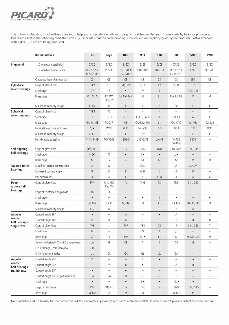
Brand/Suffixes FAG Koyo NKE NSK NTN SKF SNR TWB
In general 1 / 2 one/two dustshields Z / 2Z Z / ZZ Z / 2Z Z / ZZ Z / ZZ Z / 2Z Z / ZZ Z / ZZ
1 / 2 one/two rubber seals RSR / 2RSRHRS / 2HRS
RS / 2RS RSR / 2RSRRS2 / 2RS2
DU / DDU LU / LLU RS1 / 2RS1RSH / 2RSH
E / EE RS / 2RS
Clearance lager than normal C3 C3 C3 C3 C3 C3 J30 C3
Cylindricalroller bearings
Cage of glass-fibre TVP2 FG TVP, TVP3 T, T7 T2 P, PH G15 T
Steel cage –, (JP1) FS • W J J G13, G28 –
Brass cage M1, M1A FY, FWLPR, LY
M, M6, MA M L1 MA, M, ML M M
Maximum capacity design E, EX R E E E EC E E
Sphericalroller bearings
Cage of glass-fibre TVPB FG – H – – – –
Steel cage • FC, FP CE, • C, CD, EA, J J C(J), CC A C
Brass cage MA, M, MB FY, Q, R MB CAM, M, MB L1 CA, CAC M, MB CA, MB
Lubrication groove and holes S, • W33 W33 E4, W33 D1 W33 B33 W33
Maximum capacity design E, E1 E E E, • E E E E
For vibratory stressing T41A, T41D ROVS502 SQ34 U15VS, VB UAVS1 VA405 VA406
F800 –
Self-aligningball bearings
Cage of glass-fibre (TV), TVH – TV TNG TNH TN, TN9 G14, G15 –
Steel cage –, (•) FC • J, • • J, • • –
Brass cage M FY – M M M M M
Tapered roller bearings
Modified internal construction A A – HR... – A A, C, V –
Increased contact angle B C B C, D C B B –
ISO dimensions X X X X X, U X X X
Deepgroove ballbearings
Cage of glass-fibre TVH MN, MGFN, FG
TV TNG T2 TN9 G14, G15 –
Cage of reinforced polyamide TB FT TB – – – – –
Steel cage • • • • J • • •
Brass cage M, MA FY, P M, MA M L1 M, MA MA, M, MB M
Maximum capacity design B, C R – – – E A –
Angularcontactball bearingsSingle row
Contact angle 30° • • A – • A – –
Contact angle 40° B B B B B B B B
Cage of glass-fibre TVP – TVP T85 T2 P G14, G15 T
Steel cage JP • J W J J, F – •
Brass cage MP FY MP M, • L1 M M, MB, MA M
Universal design in X and O arrangement UA G CB G G CB G –
O / X arranges, zero clearance UO – – – – – – –
O / X lightly preloaded UL GL GA GL GL GA – –
Angularcontactball bearingsDouble row
Contact angle 25° B – – B • – A –
Contact angle 32° – • B • – A B –
Contact angle 35° • – • – – – – –
Contact angle 45° + split inner ring DA DAC D – – D – –
Steel cage • • • J, • • J1, • • –
Cage of glass-fibre TVH MN, FG TV TNG – TN9 G14, G15 –
Brass cage M, MA FY M M – M, MA M –
No guarantee and no liability for the correctness of the information provided in this cross-reference table. In case of doubt please contact the manufacturer.
The following decoding list of suffixes is meant to help you to decode the different usage of most frequently-used suffixes made by bearings producers. Please note that in the following chart the symbol „•” indicates that the corresponding suffix code is not explicitly given by the producer. Suffixes marked with a dash „–“ are not being produced.

Section Lengh ranges Cross section Angle ~kg/m Max. belt speed
Bending frequency
Min pulley
Temperaturerange
Standards
inch mm width x height m/s diameter
inch Li mm Li
Z /M 23 – 140 584 – 3556 10 x 6 38° 0.057 30 60 45 -40 – 80°C DIN 2215
A 14 – 300 355 – 7620 13 x 8 38° 0.108 30 60 71 -40 – 80°C ISO 4184
B 18 – 600 457 – 15240 17 x 11 38° 0.179 30 60 112 -40 – 80°C
C 36 – 600 914 – 15240 22 x 14 38° 0.320 30 60 180 -40 – 80°C
D 80 – 600 2032 – 15240 32 x 20 38° 0.672 30 60 315 -40 – 80°C
E 80 – 600 2032 – 15240 40 x 25 38° 1.041 30 60 450 -40 – 80°C
mm Ld
SPZ 637 – 3556 9,7 x 8 36° 0.086 40 100 63 -40 – 80°C DIN 7753/1
SPA 890 – 7620 12,7 x 10 36° 0.128 40 100 90 -40 – 80°C ISO 4184
SPB 890 – 15240 16,3 x 13 36° 0.210 40 100 140 -40 – 80°C
SPC 1524 – 15240 22 x 18 36° 0.390 40 100 224 -40 – 80°C
inch La mm La
3V 25 – 140 635 – 3556 9,5 x 8 38° 0.075 40 100 63 -40 – 80°C RMA/MPTA
5V 50 – 600 1270 – 15240 15,9 x 13 38° 0.207 40 100 140 -40 – 80°C
8V 80 – 600 2032 – 15240 25,4 x 23 38° 0.552 40 100 315 -40 – 80°C
mm Ld
XPZ 560 – 3550 9,7 x 8 36° 0.075 50 120 50 -40 – 80°C DIN 7753/1
XPA 560 – 4500 12,7 x 10 36° 0.112 50 120 63 -40 – 80°C ISO 4184
XPB 580 – 7620 16,3 x 13 36° 0.184 50 120 100 -40 – 80°C
*9000
XPC 650 – 7620 22 x 18 36° 0.343 50 120 160 -40 – 80°C
*12500
inch Li mm Li
ZX 22 – 100 559 – 2540 10 x 6 38° 0.055 50 120 40 -40 – 80°C DIN 2215
AX 22 – 70 355 – 7620 13 x 8 38° 0.070 50 120 63 -40 – 80°C ISO 4184
*400 *10160
BX 23 – 300 584 – 7620 17 x 11 38° 0.152 50 120 90 -40 – 80°C
*400 *10160
CX 24 – 300 610 – 7620 22 x 14 38° 0.272 50 120 140 -40 – 80°C
*600 *15240
DX 80 – 300 2032 – 7620 32 x 20 38° 0.571 50 120 280 -40 – 80°C
*15240
inch La mm La
3VX 22 – 140 560 – 3550 9,5 x 8 38° 0.066 50 120 56 -40 – 80°C RMA/MPTA
5VX 35 – 300 890 – 7620 15,9 x 13 38° 0.182 50 120 112 -40 – 80°C
*354 *9000
8VX 100 – 300 2540 – 7620 25 x 23 38° 0.486 50 120 280 -40 – 80°C
*600 *15240
* on request
This technical data sheet serves only as a technical guide and offers no guarantee of completeness or absolute accuracy.
TECHNICAL DATA SHEET: V-BELTS
SWR-Europe - V-belts for every application
Innovative manufacturing methods with over a 50 years‘ experience in producing V-belts are the guarantors of consistently high quality.
All products are electrically conductive in accordance with DIN ISO 1813. The SWR V-belts are fully suitable for tropical regions. They are conditionally resistant to oil and heat up to 120°C.
Flawless, reliable and durable products are the result of the most stringent quality controls and the latest production technologies.

* for further properties see catalog** upon request
COMPARISON TABLE: PLAIN BEARINGS
KS Gleitlager is a specialist in high-precision sliding elements within the Kolbenschmidt Pierburg Group.
The introduction of new technologies in production and surface treatment, innovative development work and a clear customer orientation have made KS Gleitlager one of the world‘s leading suppliers of metal plain bearings and metal polymer bearings (KS PERMAGLIDE®).
100% made in Germany!
Design KS PERMAGLIDE®(PMG)
INA SKF GGB Federal Mogul Glycodur
M GroupTechnymon
Bushings PAP EGB(Z) PCM PM / MB PG P
Flange bushings PAF EGF PCMF BB PBG F
Washers PAW EGW PCMW WC PXG W
Strips PAS EGS PCMS S PLG S
Material
P1maintenance-free, suitable for dry run
P10 - standard material= leaded*
Composite F DU
P11 - special material = P10 + improved corrosion
resistance*E40 (B) DUB
P14 - standard material= lead-free* E40 Composite E DP4 Glycodur F MU
P147 - special material = P14 + improved corrosion
resistance**
P2low-maintenance,
(distribution pockets)P20 - standard material
= leaded*
E50 Composite M DX Glycodur A MX
P200 - standard material= lead-free*
This comparison table serves only as a technical guide and offers no guarantee of completeness or absolute accuracy.

Sketch* Sealingmaterial
Operatingtemperature
PICARD Dichto-matik
SKF Simrit Stefa Action-Seal Goetze Kaco Eriks
Standard(NBR)
-40oC bis +100 oC
BA WA HMS5 RG A CB SC WDR827 N DG R
Standard(NBR)
-40oC bis +100 oC
B1 WB CRS1 R B BB SB WDR822 N DF M
Standard(NBR)
-40oC bis +100 oC
B2 WC CRSH1 R C DG SA WDR824 N DFK GV
Standard(NBR)
-40oC bis +100 oC
BASL WASHMSA10
RGASL CC TC WDR827 S DGS RST
Standard(NBR)
-40oC bis +100 oC
B1SL WBS CRSA1 R BSL BC TB WDR822 S DFS MST
Standard(NBR)
-40oC bis +100 oC
B2SL WCS CRSHA1 R CSL DC TA WDR824 S DFSK GVSTO
Standard(NBR)
-40oC bis +100 oC
BADUO WAD ADUO CK CK WDR827 D DGD R-DUO
Standard(NBR)
-40oC bis +100 oC
B1DUO WBD BDUO BK BK WDR822 D DFD M-DUO
Standard(NBR)
-40oC bis +100 oC
BAOF WAO AOF CD DE RZV
Standard(NBR)
-40oC bis +100 oC
B1OF WBO BOF BD DC MZV
Fluororubber(FKM)
-30oC bis +200 oC
VIT VIA HMS5 V BAUM Viton GR
Fluororubber(FKM)
-30oC bis +200 oC
VITSL VIAS HMSA10 V BAUMSL
This comparison table serves only as a technical guide and offers no guarantee of completeness or absolute accuracy.
COMPARISON TABLE: OIL SEALS
The standard oil seals are made of acrylonitrile-butadiene rubber (NBR). They can withstand temperatures from -40°C up to +100°C (up to 120°C for a brief period of time).
As for the SKF oil seals made of fluoro rubber, R/RG is replaced by V.
basic form
basic form
basic form
with a protective lip
with a protective lip
with a protective lip
with 2 sealing lips
with 2 sealing lips
without a spring
without a spring
basic form
with a protective lip
H
H
H
H
H
H
H
H
H
H
H
H
*Source: DICHTOMATIK

OVERVIEW OF DICHTOMATIK BOX RANGE
20x 20x 20x 20x 20x 20x
2,9x1,78ARP/BS 006
3,68x1,78ARP/BS 007
4,48x1,78ARP/BS 008
5,28x1,78ARP/BS 009
6,07x1,78ARP/BS 010
7,66x1,78ARP/BS 011
13x 13x 13x 13x 20x
13,95x2,62ARP/BS 113
12,37x2,62ARP/BS 112
10,78x2,62ARP/BS 111
9,19x2,62ARP/BS 110
9,25x1,78ARP/BS 012
--
13x 13x 13x 10x
15,54x2,62ARP/BS 114
17,13x2,62ARP/BS 115
18,72x2,62ARP/BS 116
18,64x3,53ARP/BS 210
-- --
10x 7x 7x 7x
37,69x3,53ARP/BS 222
37,47x5,33ARP/BS 325
40,65x5,33ARP/BS 326
43,82x5,33ARP/BS 327
-- --
10x 10x 10x 10x 10x
36,10x3,53ARP/BS 221
34,52x3,53ARP/BS 220
32,92x3,53ARP/BS 219
31,34x3,53ARP/BS 218
29,75x3,53ARP/BS 217
--
10x 10x 10x 10x 10x 10x
20,22x3,53ARP/BS 211
21,82x3,53ARP/BS 212
23,40x3,53ARP/BS 213
24,99x3,53ARP/BS 214
26,58x3,53ARP/BS 215
28,17x3,53ARP/BS 216
O-RING BOX G NBR 70„Inches“ - Standard30 dimensions = 382 pieces
18x 18x 18x 18x 17x 17x
3x2 4x2 5x2 6x2 7x2 8x2
14x 14x 14x 14x 17x
14x2,5 12x2,5 11x2,5 10x2,5 10x2 --
14x 14x 14x 12x
16x2,5 17x2,5 19x2,5 19x3 -- --
12x 9x 9x 9x
38x3 38x4 42x4 45x4 -- --
12x 12x 12x 12x 12x
36x3 35x3 33x3 32x3 30x3 --
12x 12x 12x 12x 12x 12x
20x3 22x3 24x3 25x3 27x3 28x3
O-RING BOX H NBR 70Standard metric sizes30 dimensions = 404 pieces
20x 20x 20x 20x 20x 19x
2,9x1,78XR-006
3,68x1,78XR-007
4,48x1,78XR-008
5,28x1,78XR-009
6,07x1,78XR-010
7,66x1,78XR-011
13x 13x 13x 13x 20x
13,95x2,62XR-113
12,37x2,62XR-112
10,78x2,62XR-111
9,19x2,62XR-110
9,25x1,78XR-012
--
13x 13x 13x 10x
15,54x2,62XR-114
17,13x2,62XR-115
18,72x2,62XR-116
18,64x3,53XR-210
-- --
9x 6x 6x 6x
37,69x3,53XR-222
37,47x5,33XR-325
40,65x5,33XR-326
43,82x5,33XR-327
-- --
10x 10x 10x 10x 10x
36,10x3,53XR-221
34,52x3,53XR-220
32,92x3,53XR-219
31,34x3,53XR-218
29,75x3,53XR-217
--
10x 10x 10x 10x 10x 10x
20,22x3,53XR-211
21,82x3,53XR-212
23,40x3,53XR-213
24,99x3,53XR-214
26,58x3,53XR-215
28,17x3,53XR-216
X-RING BOX Q XR NBR 70
30 dimensions = 377 pieces
Image: DICHTOMATIK
Image: DICHTOMATIK
Image: DICHTOMATIK