Embed Size (px)
Citation preview

Operator´s Manual
Vibratory plate
BPU2540A, 3050A, 3750Ats
0203079en 005
10.2010

ManufacturerWacker Neuson SEPreußenstraße 4180809 Münchenwww.wackerneuson.com Tel.: +49-(0)89-354 02-0Fax: +49-(0)89-354 02-390
Translation of the original operator's manual in German

1 Foreword
3
1 Foreword
This operator's manual contains information and procedures for the safe opera-tion and maintenance of your Wacker Neuson machine. In the interest of your own safety and to prevent accidents, you should carefully read through the safety information, familiarize yourself with it and observe it at all times.This operator's manual is not a manual for extensive maintenance and repair work. Such work should be carried out by Wacker Neuson service or authorized specialists.
The safety of the operator was one of the most important aspects taken into con-sideration when this machine was designed. Nevertheless, improper use or in-correct maintenance can pose a risk. Please operate and maintain your Wacker Neuson machine in accordance with the instructions in this operator's manual. Your reward will be troublefree operation and a high degree of availability.
Defective machine parts must be replaced immediately!Please contact your Wacker Neuson representative if you have any questions concerning operation or maintenance.
All rights reserved, especially reproduction and distribution rights.Copyright 2011 Wacker Neuson SE
No part of this publication may be reproduced in any form or by any means, elec-tronic or mechanical, including photocopying, without the expressed written per-mission of Wacker Neuson.Any type of reproduction, distribution or storage on data media of any type and form not authorized by Wacker Neuson represents an infringement of copyright and will be prosecuted. We expressly reserve the right to make technical modifications – even without special notice – which aim at further improving our machines or their safety stan-dards.

4
TABLE OF CONTENTS
DESCRIPTION 23
Description of function 23
TRANSPORT TO WORK SITE, RECOMMENDATIONS ON COMPACTION 24
Transport to work site 24Recommendations on compaction 24
OPERATION 25
Engine check before starting 25Starting the engine 25Operation the engine 27Forward and reverse motion 27Stopping the engine 28
MAINTENANCE 29
Maintenance schedule 29Engine oil 30Hydraulic control 31Exciter 31Exciter V-belt 31Fuel strainer cup cleaning 32Spark plug 32Carburettor adjustment 32Air filter service 33
FAULTS 34
Reverse speed too low 34Forward speed too low 34No advance 34Loss of hydraulic oil 34Engine does not start 34

BPU 2 Safety
Operator's manual 5
2 Safety
2.1 Principle
State of the artThis machine has been constructed with state-of-the-art technology according to the recognized rules of safety. Nevertheless, when used improperly, dangers to the life and limb of the operator or to third persons or damage to the machine or other materials cannot be excluded.
Proper useThe machine must only be used for the following purposes:
Compaction of soils.Compaction of asphalt.Shaking in of paving stones.
The machine may not be used for the following purposes:Compaction of intensely cohesive soils.Compaction of frozen soils.Compaction of hard, non-compactable soils.Compaction of soils that are not capable of bearing a load.
Its proper use also includes the observance of all instructions contained in this operator's manual as well as complying with the required service and mainte-nance instructions.Any other use is regarded as improper. Any damage resulting from improper use will void the warranty and the liability on behalf of the manufacturer. The operator assumes full responsibility.
Structural modificationsNever attempt to modify the machine without the written permission of the man-ufacturer. To do so will endanger your safety and the safety of other people! In addition, this will void the warranty and the liability on behalf of the manufacturer.Especially the following are cases of structural modifications:
Opening the machine and the permanent removal of components from Wacker Neuson.Installing new components which are not from Wacker Neuson and not equiv-alent to the original parts in design and quality.Installation of accessories which are not from Wacker Neuson.
It is no problem to install spare parts from Wacker Neuson.It is no problem to install accessories that are available in the Wacker Neuson product range of your machine. Please refer to the installation regulations in this operator's manual.

2 Safety BPU
6 Operator's manual
Requirements for operationThe ability to operate the machine safely requires:
Proper transport, storage and setup.Careful operation.Careful service and maintenance.
OperationOperate the machine only as intended and only when in proper working condi-tion.Operate the machine in a safety-conscious manner with all safety devices at-tached and enabled. Do not modify or disable any safety devices.Before starting operation, check that all control and safety devices are function-ing properly.Never operate the machine in a potentially explosive environment.
SupervisionNever leave the machine running unattended!
MaintenanceRegular maintenance work is required in order for the machine to operate prop-erly and reliably over time. Failure to perform adequate maintenance reduces the safety of the machine.
Strictly observe the prescribed maintenance intervals.Do not use the machine if it requires maintenance or repairs.
MalfunctionsIf you detect a malfunction, you must shut down and secure the machine imme-diately.Eliminate the malfunctions that impair safety immediately!Have damaged or defective components replaced immediately!For further information, refer to chapter Troubleshooting.
Spare parts, accessoriesUse only spare parts from Wacker Neuson or such that are equivalent to the orig-inal parts in design and quality.Only use accessories from Wacker Neuson.Non-compliance will exempt the manufacturer from all liability.

BPU 2 Safety
Operator's manual 7
Exclusion of liabilityWacker Neuson will refuse to accept liability for injuries to persons or for damage to materials in the following cases:
Structural modifications.Improper use.Failure to comply with this operator's manual.Improper handling.Using of spare parts which are not from Wacker Neuson and not equivalent to the original parts in design and quality.Using of accessories which are not from Wacker Neuson.
Operator's manualAlways keep the operator's manual near the machine or near the worksite for quick reference. If you have misplaced the operator's manual or require an additional copy, con-tact your Wacker Neuson representative or download the operator's manual from the Internet (www.wackerneuson.com).Always hand over this operator's manual to other operators or to the future owner of the machine.
Country-specific regulationsObserve the country-specific regulations, standards and guidelines in reference to accident prevention and environmental safety, for example those pertaining to hazardous materials and wearing protective gear.Complement the operator's manual with additional instructions taking into ac-count the operational, regulatory, national or generally applicable safety guide-lines.
Operator's controlsAlways keep the operator's controls of the machine dry, clean and free of oil or grease.Operating elements such as ON/OFF switch, gas handles etc. may not be locked, manipulated or changed without authorization.
CleaningAlways keep the machine clean and be sure to clean it each time you have fin-ished using it.Do not use gasoline or solvents. Danger of explosion!Do not use high pressure washers. Permeating water can damage the machine. When electrical equipment is present, this can pose a serious injury risk from electric shocks.

2 Safety BPU
8 Operator's manual
Checking for signs of damageInspect the machine when it is switched off for any signs of damage at least once per work shift.Do not operate the machine if there is visible damage or defects.Have any damage or defects eliminated immediately.
2.2 Qualification of the operating personnel
Operator qualificationsOnly trained personnel are permitted to start and operate the machine. The fol-lowing rules also apply:
You are at least 18 years of age.You are physically and mentally fit.You have received instruction on how to independently operate the machine.You have received instruction in the proper use of the machine.You are familiar with required safety devices.You are authorized to start machines and systems in accordance with the standards governing safety.Your company or the operator has assigned you to work independently with this machine.
Incorrect operationIncorrect operation or misuse by untrained personnel can endanger the health and safety of the operator or third persons and also cause machine and material damage.
Operating company responsibilitiesThe operating company must make the operator's manual available to the oper-ator and ensure that the operator has read and understood it.
Work recommendationsPlease observe the recommendations below:
Work only if you are in a good physical condition.Work attentively, particularly as you finish.Do not operate the machine when you are tired.Carry out all work calmly, circumspectly and carefully.Never operate the machine under the influence of alcohol, drugs or medica-tion. This can impair your vision, reactions and your judgment.Work in a manner that does not endanger others.Ensure that no persons or animals are within the danger zone.

BPU 2 Safety
Operator's manual 9
2.3 Protective gear
Work clothingClothing should be appropriate, i.e. should be close-fitting but not restrict your movement.When on construction sites, do not wear long hair loosely, loose clothing or jew-elry including rings. These objects can easily get caught or be drawn in by mov-ing machine parts.Only wear clothing made of material that is not easily flammable.
Personal protective gearWear personal protective gear to avoid injuries or health hazards:
Non-skid, hard-toed shoes.Work gloves made of durable material.Overalls made of durable material.Hard hat.Ear protection.
Ear protectionThis machine generates noise that exceeds the country-specific permissible noise levels (individual rating level). It may therefore be necessary to wear ear protection. You can find the exact value in the chapter Technical Data.When wearing ear protection while working, you must pay attention and exercise caution because your hearing is limited, e.g. in case someone screams or a sig-nal tone sounds.Wacker Neuson recommends that you always wear ear protection.
2.4 Transport
Switching off the machineBefore you transport the machine, it must be switched off, and the engine must be given sufficient time to cool down.
Center pole in transport positionBefore commencing transport, move the center pole to the transport position. Let the center pole latch into its lock.
Observing hazardous materials regulationsObserve the national safety guidelines and the hazardous materials regulations that apply to the respective means of transportation.

2 Safety BPU
10 Operator's manual
LiftingWhen lifting the machine, observe the following instructions:
Designate a skilled person to guide you for the lifting procedure.You must be able to see or hear this person.Use only suitable and certified hoisting gear, lifting tackle and load-bearing equipment with sufficient lifting capacities.Only use the attachment points described in the operator's manual.Attach the machine securely to the hoisting gear.Ensure that no one is nearby or under the machine.Do not climb onto the machine.
Loading the machineLoading ramps must be able to bear the load and be in a stable position.Make sure that no one can be endangered if the machine slips away or tips over or if machine parts suddenly move upward or downward.Put the operating controls and moving parts in their transport position.Secure the machine with load-securing straps so that it cannot tip over, fall down or slide away. Only use the attachment points described in the operator's manu-al.
Transport vehicleUse only suitable transport vehicles with sufficient load-carrying capacity and suitable tie-down lugs.
Transporting the machine Secure the machine on the transport device against tilting, falling or slipping.Only use the lashing points listed in the operating instructions.Also observe the country-specific regulations, standards and guidelines.
RestartingMachines, machine parts, accessories or tools that were detached for transport purposes must be re-mounted and fastened before restarting.Only operate in accordance with the operating instructions.
2.5 Operating safety
Explosible environmentNever operate the machine in a potentially explosive environment.

BPU 2 Safety
Operator's manual 11
Work environmentFamiliarize yourself with your work environment before you start work. This in-cludes e.g. the following items:
Obstacles in the work and traffic area.Load-bearing capacity of the ground.The measures needed to cordon off the construction site from public traffic in particular.The measures needed to secure walls and ceilings.Options available in the event of an accident.
Safety in the work areaWhen working with the machine especially pay attention to the following points:
Electric lines or pipes in work area.Gas lines or water lines in the work area.
Starting the machineObserve the safety information and warning notices located on the machine and in the operator's manual.Never attempt to start a machine that requires maintenance or repairs.Start the machine as directed in the operator's manual.
Vertical stabilityAlways ensure that the machine is vertically stable and cannot tip over, roll or slide away.
Proper operator positionDo not leave the proper operator position while operating the machine.The proper operator position is behind the center pole of the machine.
Leaving the danger areaInjury may be caused by moving machines or flying materials.Ensure that other persons observe a minimum safety distance of 2 m from the machine.
Caution with movable partsKeep your hands, feet and loose clothing away from moving or rotating machine parts. Parts of your body being pulled in or crushed can cause serious injuries.

2 Safety BPU
12 Operator's manual
Switching off the machineSwitch off the engine in the following situations:
Before breaks.If you are not using the machine.
Store the machine in such a way that it cannot tilt, fall or slip.
Storage locationAfter operation, allow the machine to cool and then store it in a sealed-off, clean and dry location protected against frost and inaccessible to children.
Not using starter spraysHighly flammable starter sprays pose a fire hazard.Do not use any starter sprays.Starter sprays are highly flammable and can cause backfiring and engine dam-age.
VibrationsWhen manually operated machines are intensively used, long-term damage caused by vibrations cannot be precluded.Observe the relevant legal instructions and guidelines to minimize vibration stress.Details on vibration stress associated with the machine can be found in the chap-ter Technical Data.
2.6 Safety during the operation of vibratory plates
Integrated driving mechanismMachines with integrated driving mechanism must not be set down or stored on the transport device. The driving mechanism is only intended for transport.
Belt guardNever operate the machine without a belt guard!Exposed belts and belt pulleys are dangerous and can cause serious injuries if they pull in any part of your body or if parts are ejected.
Danger of falling over Operate the machine so that it cannot tip over or fall down from bordered areas, edges and steps.
Load-carrying capacity of the groundKeep in mind that the load-carrying capacity of the earth to be compressed or bed can be greatly reduced by the effects of vibration, for example near slopes.
BPU 2 Safety
Operator's manual 13
Avoiding crushingWhen operating the machine, pay particular attention to avoid being squeezed between the machine and an obstacle. Always look in the direction of travel!
Compacting on slopesThe following points must be observed if you plan to compact inclined surfaces (slopes, escarpments):
Always stand above the machine on a slope.Start at the bottom of a slope (slopes that can be easily managed in an up-ward direction can be safely traveled in a downward direction also).Never stand in a position where the machine could possibly fall. A slipping or tipping machine can cause serious injuries.
Not exceeding the maximum tilt positionDo not exceed the maximum tilt position (see chapter Technical Data).Only operate the machine at maximum tilt for short periods of time.
If you exceed the maximum tilt, the engine lubrication system will fail and thus inevitably damage important engine parts.
Check the effects of vibrationCompacting work in the vicinity of buildings can lead to structural damage. For this reason you must always check the possible effects of vibrations on surround-ing buildings in the run-up to work.You must take the following points into special consideration when evaluating the effects of vibration:
Vibration behavior, sensitivity and resonance frequency of surrounding build-ings.Distance of the buildings from the vibrationsite (= worksite).Condition of the soil.
You may need to carry out measurements to determine the vibration speed.You must also comply with the relevant guidelines and regulations, particularly DIN 4150-3.The foundation must also have sufficient load-bearing capacity to withstand the compaction energy. In case of doubt involve a soil mechanics specialist in the evaluation.Wacker Neuson is not liable for any structural damage.

2 Safety BPU
14 Operator's manual
2.7 Safety during the operation of combustion engines
Checking for signs of damageCheck the engine while switched off for leaks and cracks in the fuel line, tank and fuel cap at least once per work shift.Do not operate the machine if there is visible damage or defects.Have any damage or defects eliminated immediately.
Dangers during operationCombustion engines can be dangerous, particularly during operation and when refueling. Read and follow all safety instructions. Otherwise there is a risk of personal injury and/or damage to property!Do not start the engine near spilt fuel or if you smell fuel – this may cause an ex-plosion!
Remove the machine from such areas.Remove the spilt fuel immediately!
Not changing the engine speedDo not change the preset engine speed, as this may cause engine damage.
Preventing firesOpen flames and smoking are strictly prohibited in the immediate vicinity of the machine.Make sure that waste, such as paper, dry leaves or grass do not accumulate around the exhaust muffler. The waste materials may ignite.

BPU 2 Safety
Operator's manual 15
Safety precautions when refuelingPlease observe the following safety-relevant instructions when refueling:
Do not refuel near open flames.Do not smoke.Turn off the engine before refueling and allow it to cool down.Refuel in a well-ventilated environment.Wear fuel-proof protective gloves and, if there is the possibility of spraying, protective goggles and clothing.Do not inhale fuel vapors.Avoid skin and eye contact with fuel.For refueling, use clean tools such as a hopper.Do not spill fuel, especially onto hot parts.Remove any spilt fuel immediately.Use the correct fuel grade.Do not mix fuel with other liquids.Fill the tank only up to the maximum marking. If there is no Maximum mark-ing, do not fill up the tank completely.Lock the fuel cap securely after refueling.
Operation in closed roomsIn closed or partially closed rooms such as tunnels, drifts or deep trenches, en-sure sufficient ventilation and extraction by, for example, providing a powerful ex-haust air fan.Danger of poisoning! Do not inhale exhaust fumes. They contain toxic carbon monoxide that can lead to unconsciousness or death.
Caution with hot partsDo not touch any hot parts such as the engine block or exhaust muffler during operation or directly afterwards. These parts can become very hot and cause se-vere burns.
Shutting off the fuel tapWhen the machine stops, shut off the fuel tap.
Cleaning the engineClean the engine when it is cool to remove any dirt.Do not use gasoline or solvents. Danger of explosion!

2 Safety BPU
16 Operator's manual
Notes on the EPA engineCautionThis machine is equipped with an EPA-certified engine.Modifying the motor speed influences the EPA certification and emission. The motor may only be set by a skilled technician.For more detailed information, contact your nearest motor or Wacker Neuson representative.
Health hazard due to exhaust fumesWarningThe engine's exhaust fumes contain chemicals which are known to the State of California to cause cancer, congenital defects or other reproductive anomalies.
2.8 Safety during the operation of hydraulic machines
Hydraulic oilHydraulic oil is harmful to health.Wear safety glasses and safety gloves when handling hydraulic oil.Avoid direct skin contact with hydraulic oil. Remove hydraulic oil from the skin im-mediately with soap and water.Make sure that no hydraulic oil comes gets in the eyes or on the body. See a phy-sician immediately if hydraulic oil gets into the eyes or is swallowed.Do not eat and drink while handling hydraulic oil. Make sure to have extreme cleanliness. Contamination of the hydraulic oil with dirt or water can cause premature wear or failure of the machine.Dispose of left over and spilled hydraulic oil according to the applicable regula-tions for environmental protection.
2.9 Maintenance
Maintenance workService and maintenance work must only be carried out to the extent described in these operating instructions. All other procedures must be performed by your Wacker Neuson representative.For further information, refer to chapter Maintenance.
Switching off the engineBefore carrying out care or maintenance work, switch off the engine and allow it to cool down.For gasoline powered engines, you must pull off the spark plug cap.

BPU 2 Safety
Operator's manual 17
Assembling safety devicesIf it was necessary to dismantle safety devices, they must be reassembled and checked immediately after completing maintenance work.Always tighten loosened screw connections, complying with prescribed starting torque.
Handling operating fluids safelyObserve the following points when handling operating fluids, e.g. fuels, oils, greases, coolants etc.:
Always wear personal safety clothing.Avoid skin and eye contact with operating fluids.Do not inhale or swallow operating fluids.In particular, avoid contact with hot operating fluids. Burn and scalding haz-ard.Dispose of replaced or spilled operating fluids according to the applicable regulations for environmental protection.If operating fluids escape from the machine, cease operation of the machine and have it repaired immediately by your Wacker Neuson representative.

2 Safety BPU
18 Operator's manual
2.10 Safety and information labels
Your machine has adhesive labels containing the most important instructions and safety information.
Make sure that all the labels are kept legible.Replace any missing or illegible labels.The item numbers for the labels are in the parts book.
Item Label Description
1 If the machine falls, it can cause severe crushing injuries.
Only lift the machine with certified hoist and lifting tackle (safety load hook).Do not lift the machine with the exca-vator shovel by the central suspen-sion.
2 Wear personal protective gear to avoid injuries or health hazards:
Ear protection.Read the operator's manual before start-up.
3 Start-Stop.
0219
260
0219
175
0219
259

BPU 2 Safety
Operator's manual 19
4 Improper handling can cause serious damage to the engine.
When using the integrated wheels, always turn off the engine.
If the engine is running, engine lubrica-tion cannot be ensured in the transport position. There is also a danger that oil may leak out of the engine crankcase breather.
5 If the machine falls, it can cause severe crushing injuries.
Do not lift the machine by the guide handle or the center pole.
6 Guaranteed sound power level.
7 Danger of fire.Smoking and open flames are prohibited.
8 Warning of hot surface.
9 US machines Warning.
10 US machines Caution.
11 US machines Danger.
Item Label Description
0220000
0219181
0219261
WARNING
WARNUNG
ADVERTENCIAADVERTISSEMENT
0219176
CAUTION
VORSICHT
ATENCIÓNATTENTION
0219262
0218955
DANGER
GEFAHR
PELIGRODANGER
0219178
3 Technical data
20
3 Technical data
Machine
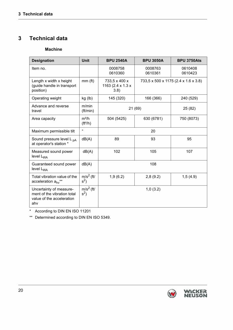
Designation Unit BPU 2540A BPU 3050A BPU 3750Ats
Item no. 00087580610360
00087630610361
06104080610423
Length x width x height (guide handle in transport position)
mm (ft) 733,5 x 400 x 1163 (2.4 x 1.3 x
3.8)
733,5 x 500 x 1175 (2.4 x 1.6 x 3.8)
Operating weight kg (lb) 145 (320) 166 (366) 240 (529)
Advance and reverse travel
m/min(ft/min) 21 (69) 25 (82)
Area capacity m²/h (ft²/h)
504 (5425) 630 (6781) 750 (8073)
Maximum permissible tilt ° 20
Sound pressure level L pA at operator's station *
* According to DIN EN ISO 11201
dB(A) 89 93 95
Measured sound power level LWA
dB(A) 102 105 107
Guaranteed sound power level LWA
dB(A) 108
Total vibration value of the acceleration ahv**
** Determined according to DIN EN ISO 5349.
m/s2 (ft/s2)
1,9 (6.2) 2,8 (9.2) 1,5 (4.9)
Uncertainty of measure-ment of the vibration total value of the acceleration ahv
m/s2 (ft/s2)
1,0 (3.2)

3 Technical data
21
Drive motor
Designation Unit BPU 2540A
BPU 3050A
BPU 3750ATS
Manufacturer Honda
Type GX160 GX270
Combustion method 4-cycle
Engine type Gasoline engine
Cooling Air cooling
Engine displacement cm³ (in³) 163 (9.9) 270 (16.5)
Cylinder 1
Rated output*
* Equivalent to the installed power output in accordance with the directive 2000/14/EC.
kW 3,1 5,2
Engine speed rpm 2,800
Fuel type Regular gasolino, lead-free(>86 oktane)
Fuel consumption l/h (qt/h) 0,8 (0,84) 1,1 (1,16)
Tank capacity l (qt) 3,1 (3.27) 5,3 (5,60)
Oil specification Fuchs Titan Unic 10W40 MC(SAE 10W40)
Oil quantity max. l (qt) 0,6 (0,63) 1,1 (1,16)
Oil quantity min. l (qt) 0,5 (0,53) 0,9 (0,95)
Spark plug BPR6ES (NGK), W20EPR-U (ND)
Spark plug air gap mm (in) 0,7-0,8 (0.027-0.031)

3 Technical data
22
Exciter
Hydraulic
Designation Unit BPU 2540A
BPU 3050A
BPU 3750ATS
Vibrations rpm (Hz) 5,400 (90)
Centrifugal force kN 25 30 37
Oil specification Fuchs Titan Unic 10W40 MC (SAE 10W40)
Oil quantity l (qt) 0.6 (0.63)
Designation Unit BPU 2540A
BPU 3050A
BPU 3750ATS
Oil specification Fuchs Renolin MR 520
Oil quantity l (qt) 0,4 (0.42)

T00845GB.fm 23
DESCRIPTION
Description of function
The vibration required for compaction is produced by the exciter (5) which is firmly joinded to the lower mass(4). This exciter (5) is designed as a central vibrator with aligned vibrations. Such a principle permits the direc-tion of vibration to be changed by turning the eccentric weights (13). In this way an infinitely variable transitionbetween vibration in forward motion, at standstill and in reverse motion is possible. This process is hydraulically controlled with the operating control handle (7) on the centre pole head (8).
Forwards On the spot Reverse
The drive engine (1) is anchored to the upper mass (3) and drives the exciter (5). The torque is transmitted bymeans of a friction connection through the centrifugal clutch (9) and the exciter V-belt (10).
The centrifugal clutch (9) interrupts the power transmission to the exciter (5) at low engine turning speed, thusallowing for a perfect idling speed of the drive engine (1). The turning speed of the engine (1) can be infinitelyadjusted by way of the throttle lever (6).
The upper (3) and lower (4) masses are connected to each other by 4 vibration-damping shock mounts (11).This damping system prevents the very high frequencies from being transmitted to the upper mass (3). As aresult the functionability of the drive engine (1) is retained in spite of the high compaction performance.
he drive engine (1) works according to the 4-stroke principle, is started by way of a recoil starter, sucks in com-bustion air over a dry air filter (12) and is air-cooled.
To facilitate the starting procedure the drive engine (1) has an decompression mechanism.

T00846GB.fm 24
TRANSPORT TO WORK SITE, RECOMMENDATIONS ON COMPACTION
Transport to work site
Conditions:- To transport the vibration plate, use only suitable lifting equipment with a minimum load-bearing capacity
of 250 kg. - Only attach suitable tackle at the central lifting point (15) provided. - Always tie down the vibratory plate by the protective frame (14) and latch the center pole in place during
transport of the vibratory plate on the loading area of a transport vehicle.
ATTENTION! The engine must be stopped when using the integrated transport device.Lubrication of the engine is not guaranteed if the engine is running when the plate is intransport position.This could lead to serious engine damages.Furthermore the danger exists that oil will spill out of the crankcase breather.
Note: Also observe the regulations in the chapter “Safety instructions“.
Recommendations on compaction
Ground conditions The max. compaction depth depends on several factors relating to the ground condition, such as moisture,grain distribution etc. It is therefore not possible to specify exact values. Recommendation: In each case determine the max. compaction depth with compaction tests and soil sam-
ples.
Compaction on slopes The following points are to be observed when compacting on sloped surfaces (slopes, embankments):
* Only approach gradients from the bottom (a gradient which can be easily overcome upwards, can also becompacted downwards without any risk).
* The operator must never stand in the direction of descent (see chapter “Safety instructions“).* The max. gradient of 20o must not be exceeded.ATTENTION! If this gradient were exceeded, this would result in a failure of the engine lubrication sys-
tem (splash lubrication) and thus inevitably lead to a breakdown of important enginecomponents.
Wrong ! Right !

T00847GB.fm 25
OPERATION
Engine check before starting
1. Oil level checkInsert dipstick in oil filler neck, but without screwing in. If oil level is low, fill to the top of the oil filler neck withhigh grade Fuchs Titan Unic 10W40 MC oil.ATTENTION! Place machine in horizontal position before checking engine oil level.
2. Dual-air cleander >Dual element type<Check the air cleaner elements to be sure they are clean and in good condition. Clean or replace the ele-ments if necessary.
3. FuelUse any regular grade automotive gasoline (unleaded gasoline is preferred) with a pump octane rating of86 or higher.Never use an oil/gasoline mixture or dirty gasoline: Avoid getting dirt, dust or water in the fuel tank.Caution: Gasoline substitutes are not recommended, they may be harmful to the fuel system compo-
nents.
Starting the engine
1. Move the fuel shut-off valve (lever in arrow direction) to the „ON“ position.
2. Move the choke lever to the CLOSE position.Note: If the engine is warm or the air temperature is high, move the control lever away from the CHOKEpostion as soon as the engine starts.

T00847GB.fm 26
OPERATION
3. Pull the throttle lever (6) back slightly.
4. Turn the engine switch to the „I“ position.
5. Pull the starter grip lightly until resistance is felt, then pull briskly.
Caution: Do not allow the starter grip to snap back against the engine. Return it gently to prevent damage to the starter.

T00847GB.fm 27
OPERATION
Operation the engine As the engine warms up, gradually move the choke lever to the OPEN position.Position the throttle lever for the desired engine speed.
Oil alert system
The oil alert system is designed to prevent engine damage caused by an insufficient amount of oil in the crank-case. Before the oil level in the crankcase drops below a safe limit, the oil alert system will automatically shutdown the engine (the engine switch will remain in the „I“ position).
Note: If engine does not start check oil level
Forward and reverse motion The engine speed can be infinitely varied with the throttle control lever (6). The direction of travel is determined with the operating control handle (7).Depending on the position of the control handle (7), the vibration plate compacts in forward direction, on thespot or in reverse direction.
Forwards On the spot Reverse

T00847GB.fm 28
OPERATION
Stopping the engine To stop the engine in an emergency, turn the engine switch to the „0“ position. Under normal conditions, use the following procedure:
1. Push the throttle lever forward all the way to the stop.
2. Turn the ignition switch to the „0“ position.
3. Turn off the fuel shut-off valve (lever in arrow direction).

T00848GB.fm 29
MAINTENANCE
Maintenance schedule
Parts Maintenance jobs Maintenance interval
Air filter Check for external damage and tight fit. dailyCheck filter cartridge, clean or replace if necessary.
Fuel tank Check tank lid for tight fit, replace if necessary.Engine oil Check oil level, top up if necessary.Exciter Check for tightness.Bowden cable Check to see smooth running.
Engine oil First oil change. after 20 hours
Ignition system Clean spark plug, check spark plug gap 0,7 mm. monthlyExciter Check attachment screws for tight fit.Hydraulic control Check oil level, top up if necessary.V-belt Check V-belt tension-retension, if need be.Protective frame Check fastening screws of protective frame and
central suspension for tight fit.
Engine oil Further oil changes. after 100 hoursExhaust muffler Remove combustion residue from spark arrester.
Exciter Check oil level-fill up, if need be. after 150 hours
Exciter Oil change. after 250 hours
Valve clearance Check, set - 0,15 mm intake valve, 0,20 mm exhaust after 300 hoursvalve.

T00848GB.fm 30
MAINTENANCE
Engine oil
Check oil level:
The engine must be horizontally place when filling in oil or checking the oil level.Check oil level with dip stick (16). If oil level is to low, top up with brand quality oil Fuchs Titan Unic 10W40 MC through oil feed opening (16).
Oil change:
Drain the oil while the engine is still warm to assure rapid and complete draining.
1. Remove the oil filler cap (16).2. Release the waist oil drain hose (2) and collect the draining oil in
an appropriate container.3. Attach the waist oil drain hose (2) back again.4. Pour the recommended oil through the oil filler tube (16) and then
check the oil level.
ATTENTION! Place machine in horizontal position beforechecking engine oil level.
5. Install the oil filter cap.
Take notice: Please pay attention to the corresponding environmental laws when disposing of used engineoil. We recommend you carry the oil in a container to a central collecting point for used oils. Donot pour used engine oil into the garbage nor into the sewer system, waste pipes or even onthe ground.

T00848GB.fm 31
MAINTENANCE
Hydraulic control
Check oil level:
1. Move centre pole into vertical position.2. Push operating control handle (7) to forward
travel position.3. Open filler bore (17).4. The oil level must reach the upper edge Oil
of the gear; add Fuchs Renolin MR 520 hydraulic fluid if required.
5. Close filler bore (17).
Hydraulic control system is self-bleeding.
Exciter
Check oil level:
1. Position vibration plate horizontally. 2. Open filler bore (19). 3. The oil level must reach the start of the thread (19) of
the filler bore.4. If necessary, pour in brand oil Fuchs Titan Unic 10W40
MC through filler bore (use funnel).5. Close filler bore (19).
Changing the oil:
1. Open filler bore (19).2. Tilt vibration plate and keep it tilted until the oil has run
out.3. Place vibration plate in horizontal position. 4. Pour in brand oil Fuchs Titan Unic 10W40 MC through
the filler bore (19).5. Close filler bore (19).
ATTENTION! Do not pour in too much oil!
Exciter V-belt
Remove belt guard. Remove the screws from the engine’s V-belt pulley and then pull off the V-belt pulley half.Take out the necessary number of discs (removal of one disc is usually enough). Place the discs just removedon the outside of the V-belt pulley half. Turn in the screws by hand and then alternately tighten while constantlyturning the engine’s V-belt pulley. Run the machine a few moments and then retighten the screws if necessary.

T00848GB.fm 32
MAINTENANCE
Fuel strainer cup cleaning
Turn the fuel valve to Off. Remove the sediment cup and O-ring, and wash them in nonflammable or high flashpoint solvent. Dry them thoroughly, and reinstall securely. Turn the fuel valve on, and check for leaks.
Spark plug
Caution: Never use a spark plug of incorrect heat range.To ensure proper engine operation, the spark plug must be properly gapped and free of deposits.
1. Remove the spark plug cap, and use a spark plug wrench to remove the plug.Warning: If the engine has been running, the muffler will be very hot. Be careful not to touch the muffler.
2. Visually inspect the spark plug. Discard it if the insulator is cracked or chipped. Clean the spark plug with awire brush if it is to be reused.
3. Measure the plug gap with a feeler gauge. The gap should be 0,7-0,8 mm (0.039-0.043 in). Correct as nec-essary by bending the side electrode.
4. Check that the spark plug washer is in good condition, and thread the spark plug in by hand to preventcross-threading.
5. After the spark plug is seated, tighten with a spark plug wrench to compress the washer.
Note: If installing a new spark plug, tighten 1/2 turn after the spark plug seats to compress the wash-er. If reinstalling a used spark plug, tighten 1/8-1/4 turn after the spark plug seats to compressthe washer.
Caution: The spark plug must be securely tightened. An improperly tightened spark plug can becomevery hot and may damage the engine.
Carburettor adjustment
* Start the engine and allow it to warm up to normal operting temperature.* With the engine idling, turn the pilot screw in or out to the setting that produces the highest idle rpm. The
correct setting will usually be approximately 2 1/4 turns from the fully closed position.
Caution: Do not tighten the pilot screw against its seat as this will damage the pilot screw or seat. Afterthe pilot screw is correctly adjusted, turn the throttle stop screw to obtain the standard idlespeed. Standard idle speed: 1 400 + 150 rpm.
1. Pilot screw 2. Throttle stop screw

T00848GB.fm 33
MAINTENANCE
Air filter service
A dirty air filter will restrict air flow to the carburettor. To prevent carburettor malfunction, service the air filterregularly. Service more freqently when operating the engine in extremely dusty areas.
Warning: Never use gasoline or low flash point solvents for cleaning the air cleaner element. A fire or ex-plosion could result.
Caution: Never run the engine without the air cleaner. Rapid engine wear will result.
1. Remove the wing nut and the air filter cover. Remove the elements and separate them. Carefully check bothelements for holes or tears and replace if damaged.
2. Foam element: Wash the element in a solution of household detergent and warm water, then rinse thor-oughly, or wash in nonflammable or high flash point solvent. Allow the element to dry thoroughly. Soak theelement in clean engine oil, and squeeze out the excess oil. The engine will smoke during initial start-up iftoo much oil is left in the foam.
3. Paper element: Tap the element lightly serveral times on a hard surface to remove excess dirt, or blow com-pressed air through the filter from the inside out. Never try to brush the dirt off; brushing will force dirt intothe fibers. Replace the paper element if it is excessively dirt.

T00849GB.fm 34
FAULTS
Reverse speed too low
Cause: - Too little hydraulic oil in the centre pole head.- Air in hydraulic control.
Remedy: - Top up hydraulic oil.- Bleed system.
Forward speed too low
Cause: - Too much oil in centre pole head.Remedy: - Correct oil level in accordance with mark.
No advance
Cause: - Mechanical fault.Remedy: - Contact Wacker service dept.
Loss of hydraulic oil
Cause: - Leaks, hydraulic hose defective.Remedy: - Change defective parts.
Note: Bleed system after every dismantling operation.
Engine does not start
Cause: - Fuel tank empty.- Fuel shut-off valve closed.- Air filter dirty.- Stop button defective.- Recoil starter defective.- Oil alert system has stopped engine.
Remedy: - Fuel up.- Open.- Clean.- Repair.- Repair.- Fill up with engine oil.

4 Emission control systems information and warranty
Operator´s manual 35
4 Emission control systems information and warranty
The Emission Control Warranty and associated information is valid only for the U.S.A., its territories, and Canada.
Emission control systems warranty statementSee the engine owner’s manual for the applicable exhaust and evaporative emis-sion warranty statement.

5 Glossary
36
5 Glossary
5.1 Use of oxygenated fuels
Some conventional gasolines are blended with alcohol. These gasolines are col-lectively referred to as oxygenated fuels. If you use an oxygenated fuel, be sure it is unleaded and meets the minimum octane rating requirement.Before using an oxygenated fuel, confirm the fuel's contents. Some states / Prov-inces require this information to be posted on the fuel pump.The following are Wacker Neuson approved percentages of oxygenates:Ethanol - (ethyl or grain alcohol) 10% by volume. You may use gasoline contain-ing up to 10% ethanol by volume (commonly referred to as E10). Gasoline con-taining more than 10% ethanol (such as E15, E20, or E85) may not be used be-cause it could damage the engine.Methanol - (methyl or wood alcohol) 5% by volume. You may use gasoline con-taining up to 5% methanol by volume, as long as it contains cosolvents and cor-rosion inhibitors to protect the fuel system. Gasoline containing more than 5% methanol by volume may cause starting and/or performance problems. It may also damage metal, rubber, and plastic parts of your fuel system.If you notice any undesirable operating symptoms, try another service station, or switch to another brand of gasoline.Fuel system damage or performance problems resulting from the use of an oxy-genated fuel containing more than the percentages of oxygenates mentioned above are not covered under warranty.

www.wackerneuson.com
EC Declaration of Conformity
ManufacturerWacker Neuson SEPreußenstraße 41, 80809 München
Product
Conformity assessment procedure acc. to 2000/14/EC, Appendix VIII, 2005/88/EC at follow-ing test center:
VDE Prüf- und Zertifizierungsinstitut GmbH, Merianstraße 28, 63069 Offenbach/MainGuidelines and standards
This is to certify that this product meets and complies with the relevant regulations and re-quirements of the following guidelines and standards:2006/42/EC,2000/14/EC, 2005/88/EC, 2004/108/EC, EN 55012:2007
Authorized person for technical documents: Axel Häret
Munich, 30.08.2010
Type BPU 2540A BPU 3050A BPU 3750Ats
Product type Vibrating plate
Item no. 0008758 0008763 0610408
Installed power output kW 3,1 5,2
Measured sound pow-er level
dB(A) 102 105 107
Guaranteed sound power level
dB(A) 108
Dr. Michael FischerHead of Research and Development
Franz BeierleinHead of product management


![WELCOME [electrical-engineering-portal.com] · Cable Installation Manual for Power and Control Cables Ninth Edition, September 2011 info@generalcable.com 1Foreword Welcome to the](https://img.dokumen.tips/doc/110x75/5f918ae4757af3600336da43/welcome-electrical-engineering-cable-installation-manual-for-power-and-control.jpg)


