Embed Size (px)
Citation preview

Eindhoven University of Technology
MASTER
BPMN 2 BPEL
research on mapping BPMN to BPEL
Blox, J.J.A.
Award date:2009
DisclaimerThis document contains a student thesis (bachelor's or master's), as authored by a student at Eindhoven University of Technology. Studenttheses are made available in the TU/e repository upon obtaining the required degree. The grade received is not published on the documentas presented in the repository. The required complexity or quality of research of student theses may vary by program, and the requiredminimum study period may vary in duration.
General rightsCopyright and moral rights for the publications made accessible in the public portal are retained by the authors and/or other copyright ownersand it is a condition of accessing publications that users recognise and abide by the legal requirements associated with these rights.
• Users may download and print one copy of any publication from the public portal for the purpose of private study or research. • You may not further distribute the material or use it for any profit-making activity or commercial gain
Take down policyIf you believe that this document breaches copyright please contact us providing details, and we will remove access to the work immediatelyand investigate your claim.
Download date: 27. Jun. 2018

EINDHOVEN UNIVERSITY OF TECHNOLOGYDepartment of Industrial Engineering
BPMN 2 BPELresearch on mapping BPMN to BPEL
ByJeroen Blox
Supervisors:
R. Eshuis (TU/e)L. Muhlenberg (Logica)
J.C. van Gaalen (Logica)
Eindhoven, March 2009


BPMN2BPEL 2
Preface
This thesis is the final product of the graduation project I conducted at Log-ica Nederland, as the final part of the Business Information Systems masterprogram at Eindhoven University of Technology. During my graduation periodI was positioned within the Working Tomorrow program, which is a programenabling graduates to perform their graduation project on challenging and inno-vative topics. The theoretical basis created during my study, could be combinedwith the practical knowledge about the topic available at Logica.
In this preface, I would like to grasp the opportunity to express thanks toa number of people. First of all, I would like to thank my supervisor fromEindhoven University of Technology for his professional and critical approachin assisting me during my master project. Our discussions were of great valuefor both the research and this thesis. I also would like to thank LambertMuhlenberg and Jan-Cees van Gaalen for their support in guiding me in theentire process, providing me with helpfull feedback and help me in defining twocase studies.
Of course, I also want to thank my colleague students at Logica for their helpin my project, but also for the pleasant time we had during and after officehours. Finally, I would like to express my gratitude to my girlfriend Noor,my family and friends for supporting me during my whole master project andmaster program.
Jeroen Blox
Eindhoven, March 20, 2009
i

BPMN2BPEL
ii

BPMN2BPEL 2
Abstract
This thesis is the end result of a master project about automatic translationfrom BPMN to BPEL. Both BPMN and BPEL are relatively new languageswhich are still under development. In the last few years, a lot of researchhas been done in the field of mapping BPMN to BPEL. Different strategiesand implementations have arisen, each with their own strengths and weak-nesses. Three main categories can be stated: structured-based, link-based andevent-action based strategies. Combining these three main categories resultsin implementations with a high level of readability and completeness. Existingimplementations try to be complete and therefore combine strategies from thethree categories, but often lack readability because of conflicting criteria.
We present a new approach for mapping BPMN to BPEL with both the read-ability and completeness criteria in mind, but focus on the readability aspect.The approach is based on an existing composition algorithm proposed by Eshuis[EG09]. In this approach, BPMN models are analyzed and synchronization de-pendencies are temporarily eliminated from the process. The remaining modelis preprocessed for finding structural properties and different concepts like im-mediate dominator, loop header and follow sets are calculated. Together withthe structural properties, the synchronization links are processed by an algo-rithm which creates a structured composition. Such a structured compositionrepresents a BPEL model and can be expressed in the official BPEL syntax.
Our approach is implemented in an Eclipse plugin and we evaluated our ap-proach by doing two case studies and comparing the results with other imple-mentations. We can conclude that our algorithm for finding synchronizationdependencies and the level of structure our generated BPEL models has, arecontributing to current strategies and implementations. Other implementationstranslate unstructured components with the link-based or event-action basedstrategies, while our approach eliminates synchronization dependencies and usesthe structured-based strategy. Different researchers agree that structured-basedtranslation results in more readable BPEL code.
Unstructured loops cannot be translated by our approach, while implementa-tions like the BABEL-tool and the Eclipse plugin can handle these unstructured
iii

BPMN2BPEL
loops. Because our approach requires a well-formed business process diagramas input model, we evaluated these well-formedness restrictions and concludethat some of these restrictions can be relaxed since the preprocessing step ofthe approach inserts dummy nodes when needed.
Also some ideas for future work are presented. The field of mapping BPMN toBPEL is changing rapidly and more implementations arise. We are convincedthat future work will narrow the gap between the design of business processesand the implementation of these processes.
iv

BPMN2BPEL 2 Contents
Contents
Preface i
Abstract iii
1 Introduction 11.1 Problem statement . . . . . . . . . . . . . . . . . . . . . . . . . . 11.2 Approach . . . . . . . . . . . . . . . . . . . . . . . . . . . . . . . 21.3 Outline . . . . . . . . . . . . . . . . . . . . . . . . . . . . . . . . 3
2 State-of-the-art: BPMN and BPEL 52.1 BPMN analyzed . . . . . . . . . . . . . . . . . . . . . . . . . . . 5
2.1.1 BPMN explained . . . . . . . . . . . . . . . . . . . . . . . 52.1.2 Evaluation of BPMN . . . . . . . . . . . . . . . . . . . . . 7
2.2 BPEL analyzed . . . . . . . . . . . . . . . . . . . . . . . . . . . . 82.2.1 BPEL explained . . . . . . . . . . . . . . . . . . . . . . . 82.2.2 Evaluation of BPEL . . . . . . . . . . . . . . . . . . . . . 10
2.3 Research on BPMN to BPEL . . . . . . . . . . . . . . . . . . . . 122.3.1 Differences between BPMN and BPEL . . . . . . . . . . . 122.3.2 Current research on mapping BPMN to BPEL . . . . . . 142.3.3 Current implementations . . . . . . . . . . . . . . . . . . 18
2.4 Conclusions . . . . . . . . . . . . . . . . . . . . . . . . . . . . . . 18
3 Mapping BPMN to BPEL 213.1 Business Process Diagram . . . . . . . . . . . . . . . . . . . . . . 223.2 Synchronization dependencies . . . . . . . . . . . . . . . . . . . . 24
3.2.1 Finding synchronization dependencies . . . . . . . . . . . 253.2.2 The complaint handling process . . . . . . . . . . . . . . . 29
3.3 Dominators, loop headers and follow sets . . . . . . . . . . . . . 303.4 BPEL grammar . . . . . . . . . . . . . . . . . . . . . . . . . . . . 313.5 The algorithm . . . . . . . . . . . . . . . . . . . . . . . . . . . . . 32
3.5.1 Adjustment of the algorithm . . . . . . . . . . . . . . . . 323.5.2 The complaint handling process . . . . . . . . . . . . . . . 34
3.6 BPEL syntax . . . . . . . . . . . . . . . . . . . . . . . . . . . . . 35
4 An Eclipse plugin 39
v
BPMN2BPEL Contents
4.1 Creating BPMN models in Eclipse . . . . . . . . . . . . . . . . . 394.2 Running the algorithm . . . . . . . . . . . . . . . . . . . . . . . . 394.3 Plugin evaluation . . . . . . . . . . . . . . . . . . . . . . . . . . . 41
5 Case studies 455.1 Loan request for an insurance company . . . . . . . . . . . . . . 45
5.1.1 Manual translation . . . . . . . . . . . . . . . . . . . . . . 475.1.2 Translating via the plugin . . . . . . . . . . . . . . . . . . 48
5.2 Total credit risk calculation . . . . . . . . . . . . . . . . . . . . . 515.2.1 Manual translation . . . . . . . . . . . . . . . . . . . . . . 535.2.2 Translating via the plugin . . . . . . . . . . . . . . . . . . 54
5.3 Conclusion . . . . . . . . . . . . . . . . . . . . . . . . . . . . . . 57
6 Evaluation of the mapping 596.1 Strengths & Weaknesses . . . . . . . . . . . . . . . . . . . . . . . 596.2 Relation with other strategies/implementations . . . . . . . . . . 60
6.2.1 Case study 1 . . . . . . . . . . . . . . . . . . . . . . . . . 626.2.2 Case study 2 . . . . . . . . . . . . . . . . . . . . . . . . . 636.2.3 Conclusion . . . . . . . . . . . . . . . . . . . . . . . . . . 64
6.3 Evaluation of well-formed BPD restrictions . . . . . . . . . . . . 656.4 Future work . . . . . . . . . . . . . . . . . . . . . . . . . . . . . . 69
7 Conclusions 717.1 Answers to the research questions . . . . . . . . . . . . . . . . . . 71
7.1.1 What is the state-of-the-art with respect to BPMN andBPEL? . . . . . . . . . . . . . . . . . . . . . . . . . . . . 71
7.1.2 How can BPMN be mapped to BPEL? . . . . . . . . . . . 727.1.3 How can our translation be evaluated compared to exist-
ing translations? . . . . . . . . . . . . . . . . . . . . . . . 727.2 Threats to validity . . . . . . . . . . . . . . . . . . . . . . . . . . 737.3 Future work . . . . . . . . . . . . . . . . . . . . . . . . . . . . . . 74
A BPMN explained A-1
B BPEL explained A-5
C Existing BPMN 2 BPEL approaches A-9
D Business Process Diagram A-11
E Input model for other implementations A-13
vi

BPMN2BPEL 2 List of Figures
List of Figures
2.1 The basic elements used in BPMN[WAD+06b] . . . . . . . . . . 62.2 A complaint handling process, adapted from [ODHA08] . . . . . 72.3 The complaint handling process in BPEL syntax . . . . . . . . . 92.4 Transformation strategies by Mendling et al.[MLZ06] . . . . . . . 152.5 The same model decomposed twice in a non-deterministic way
[VVK08] . . . . . . . . . . . . . . . . . . . . . . . . . . . . . . . . 162.6 Translation of structured BPMN components to BPEL [OADH06] 17
3.1 BPD elements displayed in a class diagram . . . . . . . . . . . . 223.2 An incorrect synchronization link, which causes a deadlock . . . 243.3 Two parallel constructs in a sequence; SESE-regions are necessary. 263.4 Algorithm for finding synchronization dependencies . . . . . . . . 283.5 A complaint handling process, adapted from [ODHA08] . . . . . 293.6 Algorithm for constructing structured compositions . . . . . . . . 333.7 Inserting unique FOLLOW node after current (l. 31 of Fig. 3.6) 343.8 Adding synchronization dependencies to the block structure . . . 343.9 The structured composition for the complaint handling process . 37
4.1 The BPMN modeling tool in Eclipse . . . . . . . . . . . . . . . . 404.2 Graphical flowchart how the plugin works . . . . . . . . . . . . . 404.3 Example of an error message of Oracle’s BPEL Process Manager 424.4 Screenshot of the execution environment . . . . . . . . . . . . . . 43
5.1 Case study 1: Loan request for an insurance company . . . . . . 465.2 Structured composition of case study 1 . . . . . . . . . . . . . . . 495.3 Part of the BPEL syntax for case study 1 . . . . . . . . . . . . . 495.4 Structured composition tree of case study 1 . . . . . . . . . . . . 505.5 Case study 2: total credit risk calculation . . . . . . . . . . . . . 525.6 Structured composition of case study 2 . . . . . . . . . . . . . . . 555.7 Part of the BPEL syntax for case study 2 . . . . . . . . . . . . . 555.8 Structured composition tree of case study 2 . . . . . . . . . . . . 56
6.1 Case study 1 translated with the Eclipse implementation [GB08] 626.2 Case study 1 translated with the BABEL-tool [OADH08] . . . . 636.3 Case study 1 translated with the Intalio-tool . . . . . . . . . . . 636.4 Case study 2 translated with the Eclipse implementation [GB08] 64
vii

BPMN2BPEL 2 List of Tables
6.5 Case study 2 translated with the Intalio-tool . . . . . . . . . . . 646.6 Start and end events with respectively an out- and indegree of
more than one. . . . . . . . . . . . . . . . . . . . . . . . . . . . . 676.7 Tasks and intermediate events that have an in- or outdegree of
more than one. . . . . . . . . . . . . . . . . . . . . . . . . . . . . 676.8 Gateways with an in- and outdegree of one can be transformed
to a task node. . . . . . . . . . . . . . . . . . . . . . . . . . . . . 68
A.1 The basic elements used in BPMN[WAD+06b] . . . . . . . . . . A-1
E.1 Case study 1 adjusted input model for the Eclipse implementationA-13E.2 Case study 1 adjusted input model for the BABEL-tool . . . . . A-13E.3 Case study 2 adjusted input model for the Eclipse implementationA-14
List of Tables
2.1 Most common BPEL elements. . . . . . . . . . . . . . . . . . . . 112.2 BPMN and BPEL compared with workflow patterns [WADH05,
WADH03] . . . . . . . . . . . . . . . . . . . . . . . . . . . . . . . 132.3 Evaluation of current approaches . . . . . . . . . . . . . . . . . . 20
3.1 before(g)- and after(g)-set for gateways of our example . . . . . 293.2 Dominators, loop headers and follow sets . . . . . . . . . . . . . 353.3 Structured composition to BPEL syntax . . . . . . . . . . . . . . 36
5.1 before(g)- and after(g)-set for gateways of case study 1 . . . . . 475.2 Dominators, loop headers and follow sets for case study 1 . . . . 485.3 before(g)- and after(g)-set for gateways of case study 2 . . . . . 535.4 Dominators, loop headers and follow sets for case study 2 . . . . 54
6.1 Evaluation of implementations . . . . . . . . . . . . . . . . . . . 656.2 Evaluation of well-formed BPD restrictions . . . . . . . . . . . . 66
7.1 Evaluation of current approaches . . . . . . . . . . . . . . . . . . 727.2 Evaluation of implementations . . . . . . . . . . . . . . . . . . . 73
C.1 Existing approaches for translating BPMN to BPEL . . . . . . . A-9
viii
BPMN2BPEL 2
Chapter 1
Introduction
The business process modeling notation (BPMN) is a graph-oriented languageoften used by domain analysts [WAD+06a] and supported by more than 50tools [Web08d]. The business process execution language for web services (WS-BPEL or BPEL in short) is a block-structured language, which is more focusedon software developers. BPEL is also supported by several execution platformsof international players [Web08c] and therefore is the standard in process-basedservice description languages. BPMN can be used to design and discuss businessprocesses with both process analysts and software engineers, while BPEL canbe used for implementation purposes. A mapping between both languages,BPMN and BPEL, would narrow the gap between design and implementationfor both business analysts and software developers.
The thesis at hand is the result of my master project conducted at LogicaNederland B.V. in Eindhoven. Logica is a leading IT and business servicescompany, employing 39,000 people across 36 countries. They enable businesstransformation for their customers through the innovative use of technology.
In this chapter we will discuss the problem statement and the research questionswe answer in this thesis. The approach we followed during the master projectis explained and in the outline a description of further chapters is given.
1.1 Problem statement
Recently some research has been done in the field of transforming a BPMN-model to structured BPEL-code [MLZ06, Whi05, OADH08, Web08a, ODHA08,RM06]. Until now, no common agreed method exists and most implementa-tions do not support unstructured BPMN-models. Only structured businessprocesses that meet a list of requirements specified by a tool, can be trans-formed by these tools. Because implementations which support unstructuredbusiness process often result in translations which are not readable by humans
1

BPMN2BPEL Introduction
[OADH08, ODHA08, MLZ06], research is necessary on this field. Completenessand readability are two important requirements for a mapping between BPMNand BPEL and will be used frequently in this thesis.
In association with Logica and Eindhoven University of Technology, we want toinvestigate the state of the art in the field of translating BPMN to BPEL. Byanalyzing current research in translating BPMN to BPEL and by evaluatingthe specifications of both languages, the strengths and weaknesses of currentapproaches can be identified. Next, we want to extend an existing algorithmpresented by Rik Eshuis [EG09] to make it suitable for mapping BPMN toBPEL. Currently this existing algorithm is used for creating block structurefrom dependency graphs according to composition theory. This algorithm willbe evaluated against the strengths and weaknesses discovered by analyzing thestate-of-the-art. Therefore, three main research question are formulated:
1. What is the state-of-the-art with respect to BPMN and BPEL?
2. How can BPMN be mapped to BPEL using the algorithm of [EG09]?
3. How can our translation be evaluated and compared to existing transla-tions?
1.2 Approach
To answer the first research question, we first explain the concepts of BPMNand BPEL. Then a literature research is conducted for both languages and thestrengths and weaknesses of each language are evaluated. Also the possibilitiesand limitations of each language are analyzed, which is needed for judging cur-rent translations. After describing both languages, current research in mappingBPMN to BPEL is analyzed and an overview is made of different strategies andimplementations currently available. We summarize the constraints, strengthsand weaknesses of different strategies (and implementations) which are used todevelop our own algorithm.
The second research question is answered both by literature research and byour own approach we present. An existing algorithm of Rik Eshuis [EG09] isused to investigate the possibilities in mapping BPMN to BPEL. Adjustmentson the existing algorithm should result in a new approach which is suitable fortranslation from BPMN to BPEL. Together with adjusting the algorithm, animplementation in Eclipse is developed and the algorithm is evaluated duringthe development. In this phase of the master project, we work according to theidea of the spiral model of Barry Boehm [Boe88]. First basic models are mappedcorrectly by the plugin, before we extend the algorithm with synchronizationdependencies and loops.
2

BPMN2BPEL Outline
An algorithm is developed for finding synchronization dependencies in singleentry, single exit-regions. The introduction of an algorithm for these synchro-nization dependencies result in less unstructured components which have to betranslated. We also evaluate well-formedness restrictions on the input BPMNmodel, to discuss the need of these restrictions.
For answering the third research question, we gather two different case studiesand use these to determine the performance of an algorithm or implementation.After defining some requirements, our own algorithm and implementation iscompared to other existing implementations or strategies described by otherresearchers.
1.3 Outline
This master thesis is structured to the presented approach.Chapter 2 contains acritical analysis of BPMN and BPEL to answer the first research question. Thestate-of-the-art with respect to BPMN and BPEL is given, but also a criticalanalysis on research done in the field of mapping those languages, is conducted.
In chapter 3 our own solution for mapping BPMN to BPEL is presented. Thealgorithm is based on an existing algorithm of Rik Eshuis. His algorithm is usedfor creating structured block diagrams with dependency graphs as input model.The algorithm is adjusted for our purpose and extended to trace synchronizationdependency relations in concurrency situations and translate them to BPELcontrol links.
An implementation of our algorithm is discussed in chapter 4. We first de-scribe the possibilities of modeling BPMN in Eclipse and then explain howour algorithm is implemented as an Eclipse plugin. The plugin is evaluatedby comparing results with manual translations we have done according to thesame algorithm as implemented.
We also present two case studies in chapter 5, which are gathered from someclients of Logica. Using these case studies we evaluate our own algorithm andin chapter 6 we compare these results with results from other implementationsand strategies. In this way we are able to identify strengths and weaknesses ofour mapping and we can propose possible improvements for mapping BPMN toBPEL. In chapter 6 we also discuss how the well-formedness restrictions whichare required by the presented approach can be relaxed.
3

BPMN2BPEL Introduction
4

BPMN2BPEL 2
Chapter 2
State-of-the-art: BPMN andBPEL
In this chapter, both BPMN and BPEL are discussed and critically analyzed todescribe the state-of-the-art. Also a brief analysis of current research on map-ping BPMN to BPEL is given. Based on the analysis, we develop requirementsand restrictions for our own algorithm presented in chapter 3.
2.1 BPMN analyzed
2.1.1 BPMN explained
In May 2004 the first version of the Business Process Modeling Notation wasproposed by the Business Process Modeling Initiative (BPMI) to provide a stan-dard visual notation for business processes. The Object Management Group(OMG) approved this first version in February 2006 as a final adopted spec-ification [OMG08b]. The intention of BPMN was to create a notation whichcould be used by both domain analysts and software developers. Also a map-ping between the graph-oriented language and the executable language BPELshould be possible when using BPMN. One of their goals is to eliminate thegap between domain and technical analysts.
BPMN is designed to support the modeling of business processes and doesn’tsupport the modeling of organizational structures, functional breakdowns, datamodels, strategy and business rules. Within the modeling aspect for businessprocesses, three main types of process models can be defined [OMG08b]:
1. Private (internal) business processes
2. Abstract (public) processes
3. Collaboration (global) processes
5

BPMN2BPEL State-of-the-art: BPMN and BPEL
Private business processes describe a set of activities inside an organization.These models will not be published in order to keep the process confidential.When different parties want to collaborate and use the different private pro-cesses, abstract processes need to be described first. Abstract processes areused to describe that part of a process which is interacting with a third party.Internal activities, which do not have a direct interface functionality, are leftoutside the scope of these models for simplicity and reasons related to confi-dentiality. Collaboration processes are abstract processes of different partiesmodeled within one single model. A collaboration process describes a processof interaction between multiple participants from an external view.
At this moment, a request for proposal is placed for a next version of the BPMNspecification. Currently the official released version is BPMN 1.1, while BPMN2.0 is under development and available as a draft. The vision of BPMN 2.0 is tohave one single specification for notation, meta model and interchange format[OMG08a]. Because BPMN 2.0 is still under development, we will use BPMN1.1 in our further research.
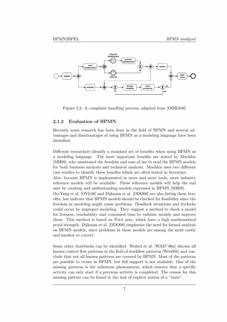
BPMN is built from a standard set of elements to create the Business Pro-cess Diagrams (BPD). These elements are basically the control flow elementsof BPMN. Swimlanes and artifacts are elements designed for representing dataand resource utilization. In Figure 2.1 the basic elements used in BPMN arecombined in one graphical overview. This overview is not a complete set of ele-ments, e.g. there are some derivatives of event-elements like timer and messageevents. Also an XOR-gateway can be modeled with or without a cross, bothare correct as long as they are used consistently. An explanation of the basicelements can be found in Appendix A. In Figure 2.2 an example BPD is givenof a complaint handling process, which will be explained and used to explainour translation in further sections.
Figure 2.1: The basic elements used in BPMN[WAD+06b]
6
BPMN2BPEL BPMN analyzed
Figure 2.2: A complaint handling process, adapted from [ODHA08]
2.1.2 Evaluation of BPMN
Recently some research has been done in the field of BPMN and several ad-vantages and disadvantages of using BPMN as a modeling language have beenidentified.
Different researchers identify a standard set of benefits when using BPMN asa modeling language. The most important benefits are stated by Muehlen[MH08], who mentioned the freedom and ease of use to read the BPMN modelsfor both business analysts and technical analysts. Muehlen uses two differentcase studies to identify these benefits which are often stated in literature.Also, because BPMN is implemented in more and more tools, more industryreference models will be available. These reference models will help the enduser by creating and understanding models expressed in BPMN [MH08].Ou-Yang et al. [OYL08] and Dijkman et al. [DDO08] are also listing these ben-efits, but indicate that BPMN models should be checked for feasibility since thefreedom in modeling might cause problems. Deadlock situations and livelockscould occur by improper modeling. They suggest a method to check a modelfor liveness, reachability and consumed time to validate models and improvethem. This method is based on Petri nets, which have a high mathematicalproof strength. Dijkman et al. [DDO08] emphasize the need for formal analysison BPMN models, since problems in these models are among the most costlyand hardest to correct.
Some other drawbacks can be identified. Wohed et al. [WAD+06a] discuss allknown control flow patterns in the field of workflow patterns [Web08b] and con-clude that not all known patterns are covered by BPMN. Most of the patternsare possible to create in BPMN, but full support is not available. One of themissing patterns is the milestone phenomenon, which ensures that a specificactivity can only start if a previous activity is completed. The reason for thismissing pattern can be found in the lack of explicit notion of a ”state”.
7
BPMN2BPEL State-of-the-art: BPMN and BPEL
Often, business analysts misuse elements of BPMN in order to increase thereadability of the BPMN model. Simulations will be false in case of misuseand different BPMN dialects are arising, which is not what the developers ofBPMN intended [MH08]. The aspect of resources is thereby completely missingin BPMN, according to the specifications [OMG08b], but the presence of poolsand lanes gives the impression of supporting resources.
Because of the freedom to misuse elements in BPMN and the high coverage ofworkflow patterns, BPMN still has some issues. The benefits which make thelanguage easy to understand and easy to use, are also risks when the specifica-tion lacks clearness.
2.2 BPEL analyzed
2.2.1 BPEL explained
OASIS (Organization for the Advancement of Structured Information Stan-dards), the organization behind BPEL, is a consortium that drives development,convergence and adoption of open standards. OASIS has developed several webservices standards since their foundation in 1993. Originally the following ba-sic specifications formed the web services space: SOAP, WSDL and UDDI[OAS07]. SOAP is a definition of an XML message protocol for basic serviceinteroperability. WSDL (Web Services Description Language) is a standard fordescribing services. UDDI (Universal Description, Discovery and Integration),developed by OASIS, basically provides the infrastructure which can publishall services in a systematic way in order to discover web services. With UDDI,web services can invoke other web services discovered via the infrastructure.
These specifications together provide the possibility to interact between webservices following a loosely coupled, platform independent model. However sys-tem integration requires more than only simple interactions; a specification fordescribing the communication between services is needed. The specificationneeds to consider data-dependent behavior, exceptional conditions and theirconsequences, and long-running interactions [OAS07]. WS-BPEL (Web Ser-vices Business Process Execution Language), in short BPEL, describes the fullinteraction possibilities between web services and the ordering of these webservices in a process. In our research, we consider version 2.0 of the BPELspecification.
Within the BPEL specification two different ways of applying the BPEL con-cepts can be found; the abstract and executable way. Abstract processes arepartially specified processes which are not intended to be executed. Executableprocesses are intended to be executed and therefore need to be fully specified.
8

BPMN2BPEL BPEL analyzed
Figure 2.3: The complaint handling process in BPEL syntax
9

BPMN2BPEL State-of-the-art: BPMN and BPEL
The available concepts for executable processes are also available for abstractprocesses, but abstract processes also have the possibility to hide some of therequired concrete operational details. Abstract processes have a descriptive roleand can give information about an executable process.
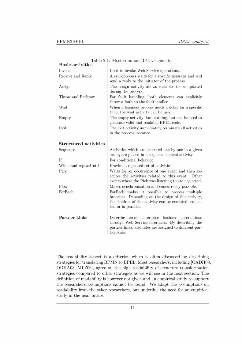
In Figure 2.3 the complaint handling example of Figure 2.2 is given in BPELcode. BPEL syntax is structured and uses nesting. Each element can haveattributes and other nested child elements. The BPEL specification contains alot of elements, which can be used for specific purposes. A full list of BPELelements can be found in [OAS07]. The most common elements can be found inTable 2.1 and are categorized into the following classes; basic activities, struc-tured activities and partner links [OAS07]. Activities perform the process logicin BPEL. A distinction is made between basic activities and structured activ-ities. Basic activities describe elemental steps of the process behavior, whilestructured activities describe the control-flow logic. Structured activities cancontain other activities. Partner links represent the interactions between differ-ent services or business processes. A more detailed description of all elementswith respect to BPEL can be found in Appendix B.
2.2.2 Evaluation of BPEL
Different researchers investigated the BPEL standard and compared the lan-guage with other web services languages.
Van der Aalst and Ter Hofstede [Web08b] created a list of 20 different work-flow patterns. Wohed et al. [WADH06] compared these workflow patterns withBPEL and created a coverage overview. This research concluded direct supportfor most of the patterns is implemented. Four major patterns which are notcovered within BPEL directly are: Discriminator, Multi-Merge, Arbitrary Cy-cles and Milestones. Milestones can be covered using a work-around, but sincethis work-around is rather complex this implementation might be improved.Because states are not supported by BPEL, variables must be introduced tokeep track of the state. In section 2.3.1 the coverage of both BPMN and BPELis discussed.
Another drawback of BPEL is the possible overlap of constructs, which resultsin different implementations. Some notations deliver more readable output,while other notations only result in correct output which is not comprehensiblefor a human being. In Figure 2.4 different BPEL structures are displayed forthe same BPMN input model. A sequence of activities can be modeled withinthe <sequence> concept for example, but can also be modeled using a <flow>concept with control links for every relation. In the BPEL structure generatedby the event-condition-action-rules strategy the control flow logic is not visiblein the structure anymore and is therefore harder to understand.
10
BPMN2BPEL BPEL analyzed
Table 2.1: Most common BPEL elements.Basic activitiesInvoke Used to invoke Web Service operations.Receive and Reply A (sub)process waits for a specific message and will
send a reply to the initiator of the process.Assign The assign activity allows variables to be updated
during the process.Throw and Rethrow For fault handling, both elements can explicitly
throw a fault to the faulthandler.Wait When a business process needs a delay for a specific
time, the wait activity can be used.Empty The empty activity does nothing, but can be used to
generate valid and readable BPEL-code.Exit The exit activity immediately terminate all activities
in the process instance.
Structured activitiesSequence Activities which are executed one by one in a given
order, are placed in a sequence control activity.If For conditional behavior.While and repeatUntil Provide a repeated set of activities.Pick Waits for an occurrence of one event and then ex-
ecutes the activities related to this event. Otherevents where the Pick was listening to are neglected.
Flow Makes synchronization and concurrency possible.ForEach ForEach makes it possible to process multiple
branches. Depending on the design of this activity,the children of this activity can be executed sequen-tial or in parallel.
Partner Links Describe cross enterprise business interactionsthrough Web Service interfaces. By describing thepartner links, also roles are assigned to different par-ticipants.
The readability aspect is a criterion which is often discussed by describingstrategies for translating BPMN to BPEL. Most researchers, including [OADH08,ODHA08, MLZ06], agree on the high readability of structure transformationstrategies compared to other strategies as we will see in the next section. Thedefinition of readability is however not given and an empirical study to supportthe researchers assumptions cannot be found. We adapt the assumptions onreadability from the other researchers, but underline the need for an empiricalstudy in the near future.
11
BPMN2BPEL State-of-the-art: BPMN and BPEL
2.3 Research on BPMN to BPEL
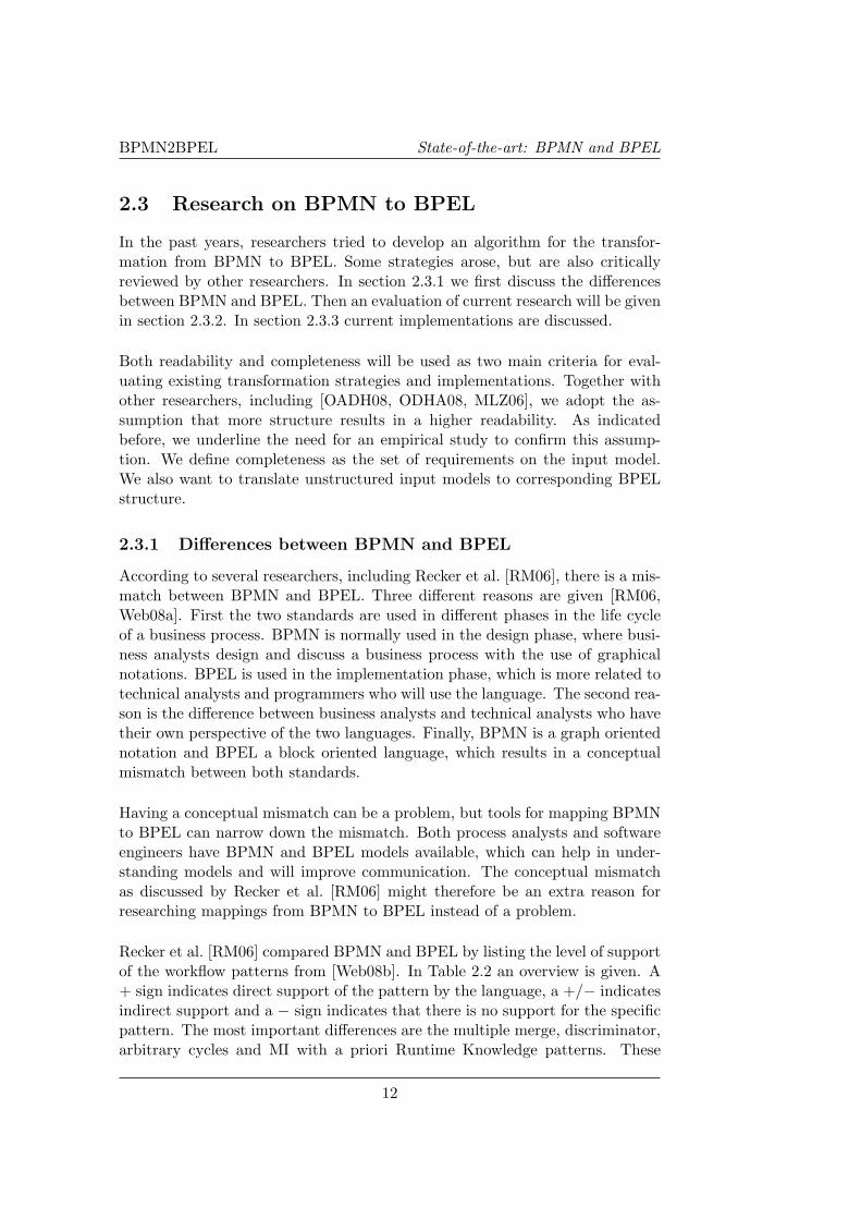
In the past years, researchers tried to develop an algorithm for the transfor-mation from BPMN to BPEL. Some strategies arose, but are also criticallyreviewed by other researchers. In section 2.3.1 we first discuss the differencesbetween BPMN and BPEL. Then an evaluation of current research will be givenin section 2.3.2. In section 2.3.3 current implementations are discussed.
Both readability and completeness will be used as two main criteria for eval-uating existing transformation strategies and implementations. Together withother researchers, including [OADH08, ODHA08, MLZ06], we adopt the as-sumption that more structure results in a higher readability. As indicatedbefore, we underline the need for an empirical study to confirm this assump-tion. We define completeness as the set of requirements on the input model.We also want to translate unstructured input models to corresponding BPELstructure.
2.3.1 Differences between BPMN and BPEL
According to several researchers, including Recker et al. [RM06], there is a mis-match between BPMN and BPEL. Three different reasons are given [RM06,Web08a]. First the two standards are used in different phases in the life cycleof a business process. BPMN is normally used in the design phase, where busi-ness analysts design and discuss a business process with the use of graphicalnotations. BPEL is used in the implementation phase, which is more related totechnical analysts and programmers who will use the language. The second rea-son is the difference between business analysts and technical analysts who havetheir own perspective of the two languages. Finally, BPMN is a graph orientednotation and BPEL a block oriented language, which results in a conceptualmismatch between both standards.
Having a conceptual mismatch can be a problem, but tools for mapping BPMNto BPEL can narrow down the mismatch. Both process analysts and softwareengineers have BPMN and BPEL models available, which can help in under-standing models and will improve communication. The conceptual mismatchas discussed by Recker et al. [RM06] might therefore be an extra reason forresearching mappings from BPMN to BPEL instead of a problem.
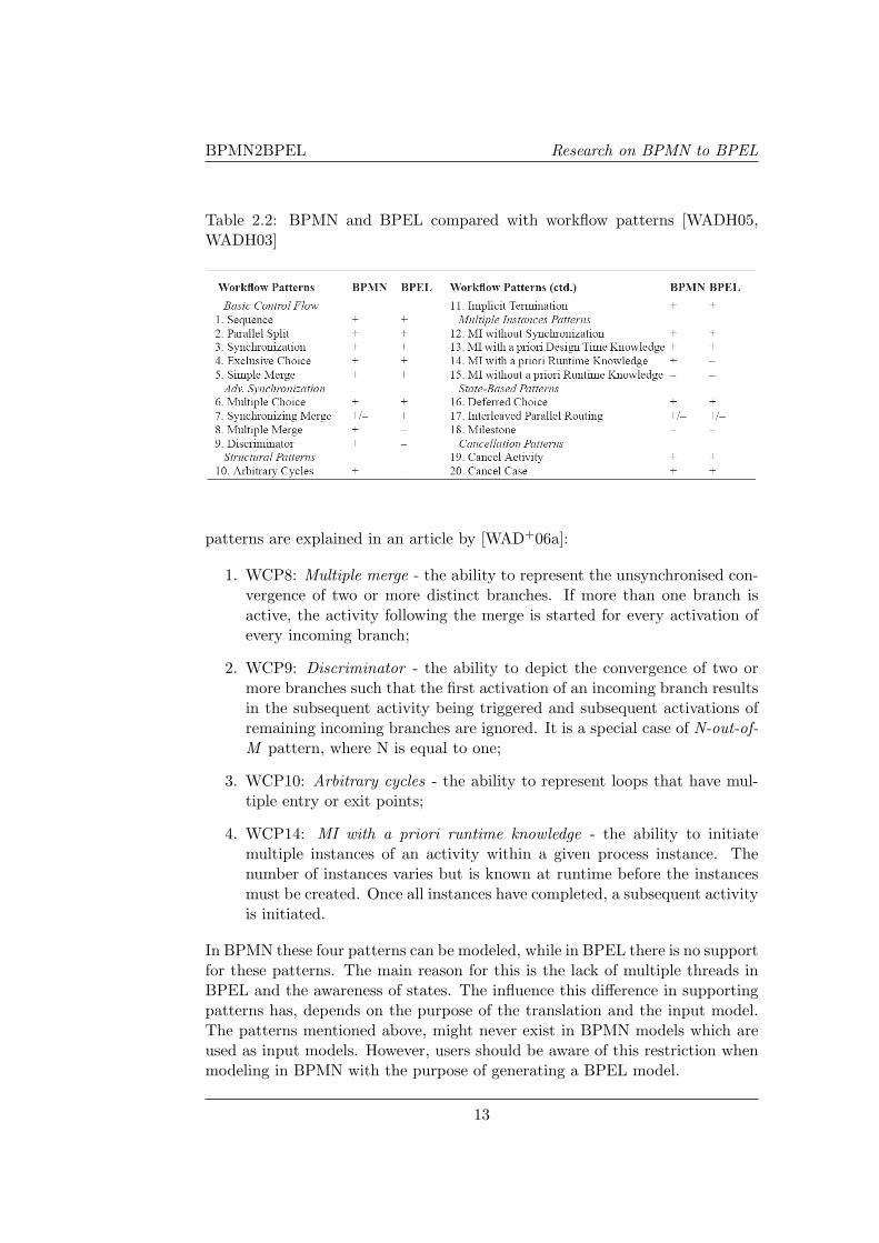
Recker et al. [RM06] compared BPMN and BPEL by listing the level of supportof the workflow patterns from [Web08b]. In Table 2.2 an overview is given. A+ sign indicates direct support of the pattern by the language, a +/− indicatesindirect support and a − sign indicates that there is no support for the specificpattern. The most important differences are the multiple merge, discriminator,arbitrary cycles and MI with a priori Runtime Knowledge patterns. These
12
BPMN2BPEL Research on BPMN to BPEL
Table 2.2: BPMN and BPEL compared with workflow patterns [WADH05,WADH03]
patterns are explained in an article by [WAD+06a]:
1. WCP8: Multiple merge - the ability to represent the unsynchronised con-vergence of two or more distinct branches. If more than one branch isactive, the activity following the merge is started for every activation ofevery incoming branch;
2. WCP9: Discriminator - the ability to depict the convergence of two ormore branches such that the first activation of an incoming branch resultsin the subsequent activity being triggered and subsequent activations ofremaining incoming branches are ignored. It is a special case of N-out-of-M pattern, where N is equal to one;
3. WCP10: Arbitrary cycles - the ability to represent loops that have mul-tiple entry or exit points;
4. WCP14: MI with a priori runtime knowledge - the ability to initiatemultiple instances of an activity within a given process instance. Thenumber of instances varies but is known at runtime before the instancesmust be created. Once all instances have completed, a subsequent activityis initiated.
In BPMN these four patterns can be modeled, while in BPEL there is no supportfor these patterns. The main reason for this is the lack of multiple threads inBPEL and the awareness of states. The influence this difference in supportingpatterns has, depends on the purpose of the translation and the input model.The patterns mentioned above, might never exist in BPMN models which areused as input models. However, users should be aware of this restriction whenmodeling in BPMN with the purpose of generating a BPEL model.
13
BPMN2BPEL State-of-the-art: BPMN and BPEL
2.3.2 Current research on mapping BPMN to BPEL
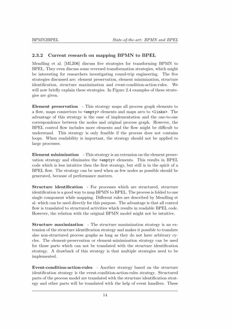
Mendling et al. [MLZ06] discuss five strategies for transforming BPMN toBPEL. They even discuss some reversed transformation strategies, which mightbe interesting for researchers investigating round-trip engineering. The fivestrategies discussed are: element preservation, element minimization, structureidentification, structure maximization and event-condition-action-rules. Wewill now briefly explain these strategies. In Figure 2.4 examples of these strate-gies are given.
Element preservation - This strategy maps all process graph elements toa flow, maps connectors to <empty> elements and maps arcs to <links>. Theadvantage of this strategy is the ease of implementation and the one-to-onecorrespondence between the nodes and original process graph. However, theBPEL control flow includes more elements and the flow might be difficult tounderstand. This strategy is only feasible if the process does not containsloops. When readability is important, the strategy should not be applied tolarge processes.
Element minimization - This strategy is an extension on the element preser-vation strategy and eliminates the <empty> elements. This results in BPELcode which is less intuitive then the first strategy, but still is in the spirit of aBPEL flow. The strategy can be used when as few nodes as possible should begenerated, because of performance matters.
Structure identification - For processes which are structured, structureidentification is a good way to map BPMN to BPEL. The process is folded to onesingle component while mapping. Different rules are described by Mendling etal. which can be used directly for this purpose. The advantage is that all controlflow is translated to structured activities which results in readable BPEL code.However, the relation with the original BPMN model might not be intuitive.
Structure maximization - The structure maximization strategy is an ex-tension of the structure identification strategy and makes it possible to translatealso non-structured process graphs as long as they do not have arbitrary cy-cles. The element-preservation or element-minimization strategy can be usedfor those parts which can not be translated with the structure identificationstrategy. A drawback of this strategy is that multiple strategies need to beimplemented.
Event-condition-action-rules - Another strategy based on the structureidentification strategy is the event-condition-action-rules strategy. Structuredparts of the process model are translated with the structure identification strat-egy and other parts will be translated with the help of event handlers. These
14

BPMN2BPEL Research on BPMN to BPEL
Figure 2.4: Transformation strategies by Mendling et al.[MLZ06]
15
BPMN2BPEL State-of-the-art: BPMN and BPEL
event handlers are similar to goto-statements in software engineering. In Figure2.4 an example of this strategy can be found; the event handler is not directlyconnected to the control flow. The advantage of this strategy is that almostany process graph, including those with unstructured loops, can be transformed.The use of event handlers however makes the generated BPEL code less under-standable because the control flow crosses the border of event handlers.
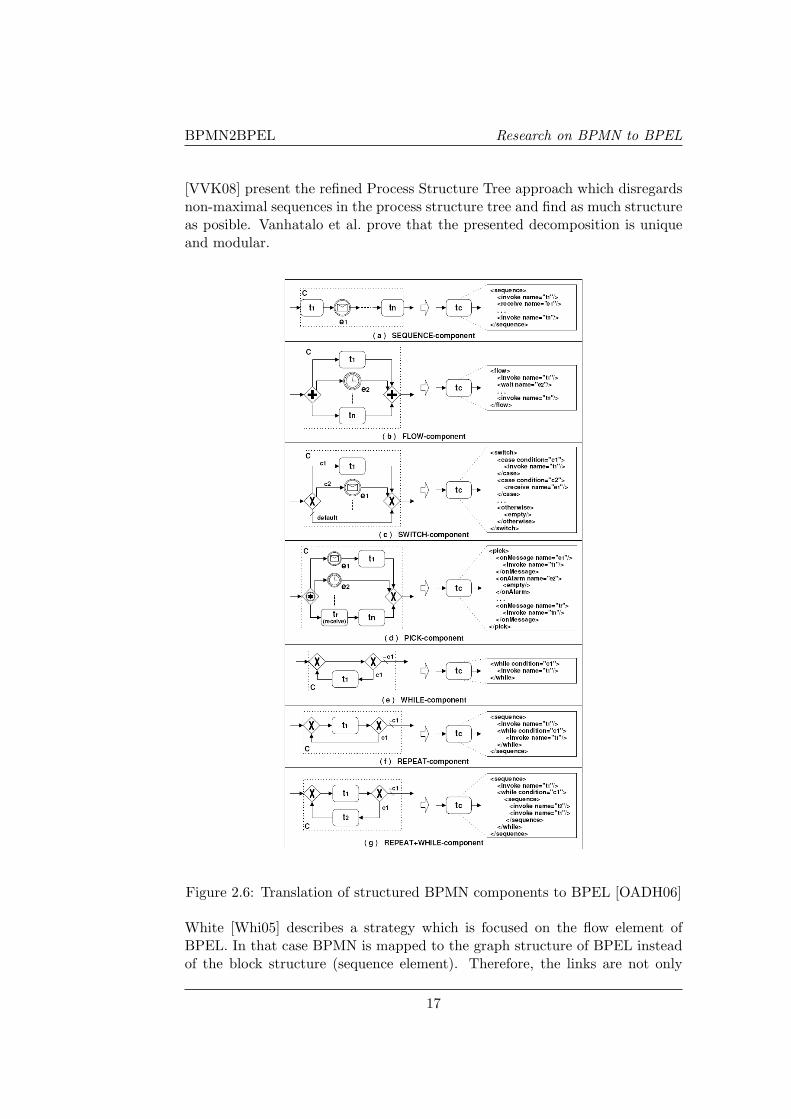
Ouyang et al. [OADH06] suggest a method for transformation with an event-action rule-based algorithm. First a Business Process Diagram (BPD) is de-composed into components. Well structured components are translated withthe structure identification strategy, see also Figure 2.6. Components whichcannot be translated with this strategy are transformed with the event-actionrule-based translation. Preconditions are defined which generate event-actionrules. These event-action rules can then be transformed to BPEL code.
In another research of Ouyang et al. [OADH08] the described method is slightlyadjusted. Petri nets are used to check the soundness and safeness of the BPD.Also dependencies between activities are described as control links, before theevent-action rule-based strategy is executed. This will result in BPEL codewith a higher level of readability compared to the case of using events, becausecontrol links are enclosed in the control flow within the generated BPEL code.In another research article[ODHA08], a new phase in the transformation processis proposed, where quasi-structured patterns are refined into well-structuredpatterns.
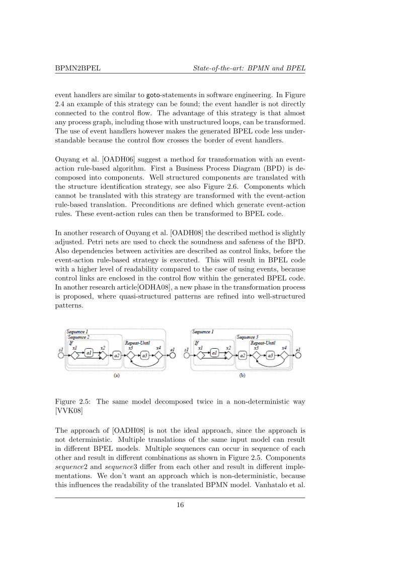
Figure 2.5: The same model decomposed twice in a non-deterministic way[VVK08]
The approach of [OADH08] is not the ideal approach, since the approach isnot deterministic. Multiple translations of the same input model can resultin different BPEL models. Multiple sequences can occur in sequence of eachother and result in different combinations as shown in Figure 2.5. Componentssequence2 and sequence3 differ from each other and result in different imple-mentations. We don’t want an approach which is non-deterministic, becausethis influences the readability of the translated BPMN model. Vanhatalo et al.
16
BPMN2BPEL Research on BPMN to BPEL
[VVK08] present the refined Process Structure Tree approach which disregardsnon-maximal sequences in the process structure tree and find as much structureas posible. Vanhatalo et al. prove that the presented decomposition is uniqueand modular.
Figure 2.6: Translation of structured BPMN components to BPEL [OADH06]
White [Whi05] describes a strategy which is focused on the flow element ofBPEL. In that case BPMN is mapped to the graph structure of BPEL insteadof the block structure (sequence element). Therefore, the links are not only
17
BPMN2BPEL State-of-the-art: BPMN and BPEL
used for synchronization purposes, but also for other relations between activ-ities. Mapping of unstructured processes might therefore be possible, but thereadability of the generated BPEL code is an issue.
2.3.3 Current implementations
Two open source BPMN2BPEL tools are currently available. BABEL1 is thebest known tool of both and is developed based on an article of Ouyang et al.[OADH08]. However, this tool is not maintained anymore since there were toomany bugs, there was too little documentation and a non-deterministic single-entry single-exit (SESE) decomposition approach was not implemented while itwas necessary [Dum09]. Vanhatalo et al. [VVK08] discuss the refined processstructure tree (PST) which is a decomposition approach that is unique andmodular. Adjusting the BABEL-tool to this PST-approach was not possibleaccording to M. Dumas [Dum09].
A new implementation based on the Process Structure Tree decomposition wasdeveloped as an Eclipse plugin available on Google code2. This implementationuses the SESE decomposition approach presented by [VVK08] to identify SESEregions and determine process components with structure. These regions arenested, such that they can be arranged to form a structure tree. Each leaf is thentranslated by the tool to a corresponding BPEL construct. Garcıa-Banuelos[GB08], developer of the Eclipse plugin, explains how to identify patterns andstructure a BPMN model into SESE regions.
Both implementations are based on the idea of combining different strategiesfor translating BPMN to BPEL. First structured components are identifiedand translated, then all elements which can be translated by the link-basedapproach are translated and finally the event-action based approach is applied.The Eclipse plugin is not based on the BABEL-tool, but the website of theBABEL-tool suggests otherwise. After a private conversation with the authors,both tools seem to be independent from each other.
2.4 Conclusions
BPMN might become an industry standard soon, but still has some issues whichhopefully have been improved in BPMN 2.0. Due to the possible ambiguity ofmodels, misunderstanding can occur and models should be checked for feasibil-ity. However, BPMN is a modeling notation which can be understood by bothbusiness analysts and technical analysts. This results in better material for dis-cussing business processes and will have a positive effect on implementations.
1BABEL: http://www.bpm.fit.qut.edu.au/projects/babel/tools/2Google code: http://code.google.com/p/bpmn2bpel/
18

BPMN2BPEL Conclusions
BPEL is a well developed standard in the field of web service specifications. Abroad range of workflow patterns can be supported by BPEL. However, thereare multiple ways of implementing the same processes, which can result inBPEL code which is hard to understand.
Different strategies for mapping BPMN to BPEL are explained in the previoussection. Each strategy has some benefits and drawbacks. Often completenessand readability are the criteria to evaluate the quality of a strategy. Both shouldbe high for an optimal transformation strategy, but can be conflicting criteria.At this moment combining strategies is the best way to create a complete andreadable model in BPEL.
One common problem of translating BPMN to BPEL is the improper modelingof an input BPMN model. Since BPMN can contain infinite loops or deadlocks,implementations can be generated when translating BPMN to BPEL whichcannot be executed. Therefore it would be important to check for soundnessand liveness in a BPMN model. Dijkman et al. [DDO08] propose an algorithmfor translating BPMN to Petri nets. With the help of Petri nets the soundnessand safeness can be checked in a formal way.
A main distinction between structured and unstructured components and pro-cesses can be found in current approaches. Often, structured components aremapped to associated BPEL constructs for improved readability. Unstructuredcomponents are mapped to control links or event handlers. Both the con-trol links and event handlers are found to be less readable compared to thestructured component translations [OADH08, ODHA08, MLZ06], but supporta broader range of input process models. Restrictions on the input processmodel like requiring a well-formed business process diagram can be relaxed inthese less readable approaches. As said, combining strategies will probably leadto a translation with the best readability and highest completeness.
Table C.1 in Appendix C, summarises the strengths, weaknesses, constraintsand completeness of existing approaches discussed earlier. This overview willalso be used for evaluating our own algorithm, which we will present in chapter3. In table 2.3 we visualised the possibilities of different approaches with amatrix. A ’+’ means that the mapping supports the component (or is found tobe readable or complete by literature), where a ’-’ means that the componentis not supported. A ’+/-’ indicates a partial support for a component.
19

BPMN2BPEL State-of-the-art: BPMN and BPEL
Table 2.3: Evaluation of current approaches
Component \Mapping A B C D E F G HReadability - +/- - - + + - +/-Completeness +/- + +/- +/- - +/- + +Structured components + + + + + + + +Structured loops - + - - + + + +Unstructured components + + + + - + + +Unstructured loops - + - - - - + +Synchronization links + +/- + + - + +/- +/-
The following mappings are displayed in table 2.3.
A: Graph structure approach (White) [Whi05]
B: A combined approach (Ouyang et al. ) [OADH08]
C: Element-preservation (Mendling et al. ) [MLZ06]
D: Element-minimization (Mendling et al. ) [MLZ06]
E: Structure-identification (Mendling et al. ) [MLZ06]
F: Structure-maximization (Mendling et al. ) [MLZ06]
G: Event-condition action-rules (Mendling et al. ) [MLZ06]
H: Pattern identification and Classification (Garcıa-Banuelos) [GB08]
20
BPMN2BPEL 2
Chapter 3
Mapping BPMN to BPEL
We have seen the differences in translations of BPMN to BPEL for businessprocesses. Structured and unstructured business processes are mapped accord-ing to different aproaches. We assume that a combination of approaches willlead to the translation with the highest level of completeness and readability.Because both requirements are conflicting, we find readability more importantthan completeness because this implies more structure in the generated BPELcode. The implementation of Garcıa-Banuelos [GB08] mentioned in section 2.3,already combines structured and unstructured approaches. First the structuredcomponents, which are identified using single entry single exit regions, are pro-cessed. The resulting part of the process is then translated using control links.We will compare this approach with a modified algorithm of Rik Eshuis [EG09],which composes services into structured processes. The generated structuredprocess model can be translated to BPEL syntax according to the structuredidentification strategy proposed by Mendling et al. [MLZ06].
We will start with using a well-formed Business Process Diagram (see section3.1), but will evaluate these constraints during the development of the algo-rithm. Starting with structured processes will match current research in thefield of BPMN to BPEL. While evaluating well-formed restrictions, we can dis-cuss if the requirements for input processes can be relaxed and if input modelswith less structure can be transformed. We also want to adjust the algorithm ofEshuis with an algorithm for finding synchronization links. These synchroniza-tion links can be mapped to the BPEL control links. The remaining process willbe structured which is possible due to the restrictions of a well-formed BusinessProcess Diagram. We focus only on the control flow aspect of BPMN modelsand will not focus on data aspects. Our goal is to develop a mapping whichis able to translate BPMN models, that meet the well-formedness restrictions,to valid BPEL syntax. Also we are interested in the added value the existingalgorithm of Eshuis can offer in the process of translating BPMN to BPEL.
21

BPMN2BPEL Mapping BPMN to BPEL
3.1 Business Process Diagram
BPMN uses Business Process Diagrams (BPDs) to describe business process.BPDs are built of a core subset of BPMN elements and described by [OADH08,ODHA08]. A BPD contains a set of objects O which can be partitioned intodisjoint sets of tasks T , events E and gateways G. Events can be partitionedinto disjoint sets of start events ES , intermediate events EI and end events EE .The intermediate events can be partitioned further into a disjoint, completeset of intermediate message events EIM and timer events EIT . Gateways can bepartitioned into disjoint sets of parallel fork gateways GF , parallel join gate-ways GJ , data-based XOR decision gateways GD, event-based XOR decisiongateways GV , and XOR merge gateways GM. Relations between objects aredefined in the control flow relation F ⊆ O ×O.
A graphical representation can be found in the class diagram in Figure 3.1,where the formal definition [OADH08, ODHA08] can be found in Appendix D.
Figure 3.1: BPD elements displayed in a class diagram
The relation F defines a directed graph with nodes(objects) and arcs(sequenceflows). However, the definition allows graphs which are unconnected, not havingstart or end events, containing objects without input or output etc. Becausewe only want a model without deadlocks and livelocks, we need to restrict thedefinition to a well-formed BPD, before we can use an algorithm on the model.
A so called well-formed BPD is a BPD which meets specific requirements. Theremaining of this section is adapted from [OADH08, ODHA08]. All tasks andevents, represented by o, can only have an indegree, in(o), of at most one and
22
BPMN2BPEL Business Process Diagram
an outdegree, out(o), of at most one.
in(o) = {x | (x, y) ∈ F ∧ y = o}
out(o) = {y | (x, y) ∈ F ∧ x = o}
Start events and end events have an indegree and outdegree respectively ofzero. Gateways however, can have more incoming or outgoing relations. Forkor decision gateways have an outdegree of more than 1, while join or mergegateways have an indegree of more than 1. Also every object of the BPD mustbe on a path from start till end event.
Definition 1. A core BPD is well-formed if relation F satisfies the followingrequirements [OADH08, ODHA08]:
- ∀ s ∈ ES , in(s) = ∅ ∧ |out(s)| = 1, i.e. start events have an indegree ofzero and an outdegree of one,
- ∀ e ∈ EE , out(e) = ∅ ∧ |in(e)| = 1, i.e. end events have an outdegree ofzero and an indegree of one,
- ∀ x ∈ T ∪ EI , |in(x)| = 1 and |out(x)| = 1 , i.e. tasks and intermediateevents have an indegree of one and an outdegree of one,
- ∀ g ∈ GF ∪ GD ∪ GV , |in(g)| = 1 ∧ |out(g)| > 1, i.e. fork or decisiongateways have an indegree of one and an outdegree of more than one,
- ∀ g ∈ GJ ∪ GM, |out(g)| = 1 ∧ |in(g)| > 1, i.e. join or merge gatewayshave an outdegree of one and an indegree of more than one,
- ∀ g ∈ GV , out(g) ⊆ EI ∪ T R, i.e. event-based XOR decision gatewaysmust be followed by intermediate events or receive tasks,
- ∀ g ∈ GD, ∃x ∈ out(g), Cond((g,x)) = ¬∧y∈out(g)\{x} Cond((g,y)), i.e.(g,x) is the default flow among all the outgoing flows from g.
- ∀ x ∈ O, ∃(s,e) ∈ ES × EE , sF*x ∧ xF*e, i.e. every object is on a pathfrom a start event to an end event.
For developing a new algorithm which can translate BPMN models to BPELcode, we will first focus only on well-formed BPDs. Later on, the constraintsof a well-formed BPD will be evaluated to see whether or not such a constraintcan be eliminated without any unintended effect on the result of our algorithm.
23
BPMN2BPEL Mapping BPMN to BPEL
3.2 Synchronization dependencies
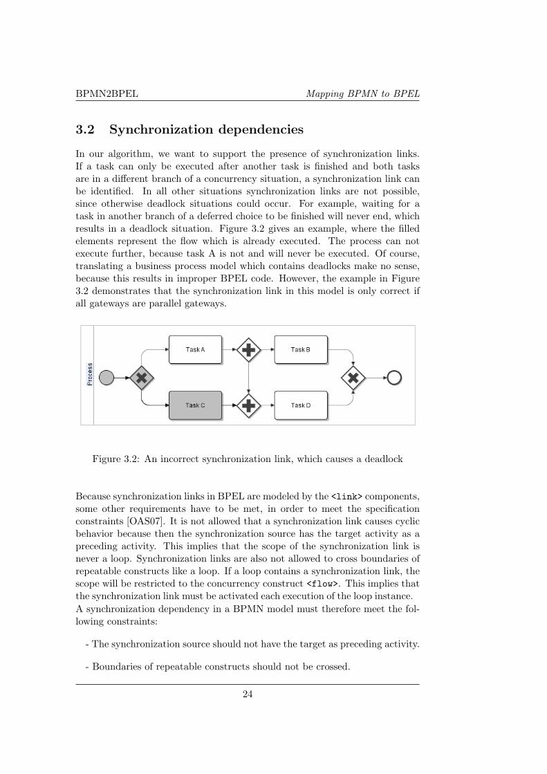
In our algorithm, we want to support the presence of synchronization links.If a task can only be executed after another task is finished and both tasksare in a different branch of a concurrency situation, a synchronization link canbe identified. In all other situations synchronization links are not possible,since otherwise deadlock situations could occur. For example, waiting for atask in another branch of a deferred choice to be finished will never end, whichresults in a deadlock situation. Figure 3.2 gives an example, where the filledelements represent the flow which is already executed. The process can notexecute further, because task A is not and will never be executed. Of course,translating a business process model which contains deadlocks make no sense,because this results in improper BPEL code. However, the example in Figure3.2 demonstrates that the synchronization link in this model is only correct ifall gateways are parallel gateways.
Figure 3.2: An incorrect synchronization link, which causes a deadlock
Because synchronization links in BPEL are modeled by the <link> components,some other requirements have to be met, in order to meet the specificationconstraints [OAS07]. It is not allowed that a synchronization link causes cyclicbehavior because then the synchronization source has the target activity as apreceding activity. This implies that the scope of the synchronization link isnever a loop. Synchronization links are also not allowed to cross boundaries ofrepeatable constructs like a loop. If a loop contains a synchronization link, thescope will be restricted to the concurrency construct <flow>. This implies thatthe synchronization link must be activated each execution of the loop instance.A synchronization dependency in a BPMN model must therefore meet the fol-lowing constraints:
- The synchronization source should not have the target as preceding activity.
- Boundaries of repeatable constructs should not be crossed.
24
BPMN2BPEL Synchronization dependencies
- Both the source and target of the dependency should be preceded by aparallel split gateway.
The concept of Dead-Path-Elimination (DPE) is also an important issue forsynchronization dependencies, since the <link> source components must beassigned a value before the targets can be processed and terminated in BPEL.With DPE the activities which are not executed can be ’garbage collected’ byassigning the value ’false’. The business process as a whole is then processedand the process can be correctly terminated when necessary. The problem ofDPE is the risk of (unintended) side effects which can occur. Van Breugel et al.[BK05] discuss these side effects and propose a modification for DPE to solvethese issues. The BPEL syntax offers a possibility to use DPE by setting thevalue of the <process>-attribute suppressJoinFailure.
A synchronization link candidate can be easily marked, since this needs to bea direct relation between a parallel fork gateway and a parallel join gateway.Other modeling notations for synchronization links do no match the well-formedBPD criteria as discussed earlier. Using multiple incoming or outgoing arcs ona node for example is not allowed because of the restrictions of a well-formedBPD. We develop a method to determine if a synchronization link candidatereally is a synchronization link. The reason for making a distinction betweennormal control flow relations and synchronization relations is the way we processboth types further in our algorithm. Synchronization relations are not used fordetermining the structure of the business process, but are only used in one ofthe last phases of the mapping. We will add the synchronization dependenciesin the structured composition created in the algorithm.
3.2.1 Finding synchronization dependencies
Synchronization dependencies are modeled by a direct relation between a par-allel split and a parallel join gateway. If there is no direct relation between twoof these gateways, there are no synchronization dependencies.
First the set of tasks and events which precede a gateway and the set of tasksand events which follow a gateway are captured for both parallel fork gatewaysand join gateways. This result in two sets of objects for a gateway g ∈ GF ∪GJ ,the before(g) and after(g)-set. The before(g)-set contains all tasks and eventswhich are always executed before the gateway can be visited. The after(g)-setcontains all tasks and events which are always executed after the gateway isvisited. The union of both sets describes the whole branch from entry node toexit node in form of tasks and events. The set branch(g) represent this unionand is defined as before(g) ∪ after(g).
During the evaluation of our algorithm, a lot of models adapted from literaturewere used to evaluate our algorithm for finding synchronization dependencies.
25

BPMN2BPEL Mapping BPMN to BPEL
Figure 3.3: Two parallel constructs in a sequence; SESE-regions are necessary.
Also two case studies described in chapter 5 were used and show the need forsingle entry, single exit (SESE) regions. The algorithm we propose worked fineas long as there were no two parallel constructs in a sequence of each other. Tosupport these situations, which we modeled in Figure 3.3, we have done somefinetuning in the algorithm and added the restriction that the gateways we areevaluating are in the same SESE-region. A SESE-region, or component, canbe defined in the following definition[OADH06]. To facilitate the definitions,Ouyang et al. specified an auxiliary function over a domain of singletons, i.e.,if X = {x}, then elt(X) = x.
Definition 2. Let BPD = (O,F , Cond) be a well-formed core BPD. C =(Oc,Fc, Condc) is a component(SESE-region) of BPD if and only if:
• Oc ⊆ O\(ES ∪ EE),
• | (∪x∈Oc in(x))\Oc |= 1, i.e. there is a single entry point outside thecomponent, which can be denoted as entry(C) = elt((∪x∈Oc in(x))\Oc),
• | (∪x∈Oc out(x))\Oc |= 1, i.e. there is a single exit point outside thecomponent, which can be denoted as exit(C) = elt((∪x∈Oc out(x))\Oc),
• there exists a unique source object ic ∈ Oc and a unique sink object oc ∈ Oc
and ic 6= oc, such that entry(C) ∈ in(ic) and exit(C) ∈ out(oc),
• Fc = F ∩ (Oc×Oc),
• Condc = Cond(Fc), i.e. the Cond function where the domain is restrictedto Fc.
The before(g), after(g) and branch(g)-sets can be defined as:
before(g) = {x | x ∈ Oc ∧ entry(C)F*x ∧ xFc*g}
after(g) = {y | y ∈ Oc ∧ gF*y ∧ yFc*exit(C)}
branch(g) = before(g) ∪ after(g) ∪ {g}
26
BPMN2BPEL Synchronization dependencies
For each parallel fork gateway f ∈ GF , beginning with the one with the smallestbefore(f)-set, a matching parallel join gateway j ∈ GJ will be found when bothsets contain the same elements, so branch(f) = branch(j) or, if there is no joingateway with the same set as the fork gateway, one of the sets is a subset of theother (branch(f) ⊆ branch(j) or branch(f) ⊇ branch(j)). A relation betweena matching fork and join gateway is not a synchronization link and the joingateway is removed from the set which is used to determine synchronizationlinks. The algorithm in Figure 3.4 shows this approach and orders the setof gateways using a while-construct [Esh05], where the smallest and largestgateways are taken for the fork and join gateway respectively. This while-construct will be terminated when all gateways are processed. By introducingthe ordering, the algorithm can be executed more efficiently because matchinggateways are found earlier. A join gateway j, which can not be matched toany fork gateway f and where a direct relation between the fork gateway f andthe join gateway j exists, can be marked as target of the synchronization link.The source of the synchronization link will be the fork gateway f of the directrelation.
All synchronization links will be stored in the set FS ⊆ F and will be pro-cessed different from other relations in the next step. We will now first explainthe algorithm for finding synchronization and use an example of a complainthandling process, which is presented in the next section.
The algorithm for finding synchronization links is listed in figure 3.4. It re-quires as input a set GF of parallel fork gateways which will be ordered bythe algorithm in ascending order of the before(g)-set size as explained before.Also a set GJ of parallel join gateways, which will be ordered in descendingorder of the before(g)-set size, is required. The algorithm looks for matchingbranch(g)-sets first and in case there is no matching, also for subsets of the forkand join gateway-branch(g)-sets. Matching gateways are skipped when furtherprocessing the algorithm. In case there is no match between a fork gateway fand a join gateway j, a synchronization link will be identified when a directrelation between both gateways can be found in F .
After introducing the before(g), after(g) and branch(g)-sets we can explainthe need for SESE-regions once more, since in Figure 3.3 all gateways whichare not part of the synchronization dependency have the same branch(g)-set.Because of the ordering in our algorithm, the two outer gateways are matchedwhich is not the situation modeled. When the algorithm is executed within aSESE-region, this problem situation can not occur.
Alternatives for the presented algorithm for finding synchronization dependen-cies are asking the user for clearness or process the whole component whichcontain a synchronization dependency as an unstructured component. Because
27

BPMN2BPEL Mapping BPMN to BPEL
1: procedure FindingSynchronization((GF , GJ ,F))2: links := ∅3: if ∃ (f, j) ∈ F | f ∈ GF ∧ j ∈ GJ then4: forktovisit := GF
5: while forktovisit 6= ∅ do6: f := the gateway with the smallest before(g)-set of forktovisit7: SearchSubsets = true8: jointovisit := GJ
9: while jointovisit 6= ∅ do10: j := the gateway with the largest before(g)-set of jointovisit11: if branch(f) = branch(j) then12: GJ := GJ\{j}13: SearchSubsets = false14: break;15: end if16: jointovisit := jointovisit\j17: end while18: if SearchSubsets = true then19: while jointovisit 6= ∅ do20: j := the gateway with the largest before(g)-set of jointovisit21: if branch(f) ⊇ branch(j) ∧(f, j) 6∈ F then22: GJ := GJ\{j}23: break;24: else if branch(f) ⊆ branch(j) ∧(f, j) 6∈ F then25: GJ := GJ\{j}26: break;27: else if (f, j) ∈ F then28: links := links ∪ {(f, j)}29: end if30: jointovisit := jointovisit\j31: end while32: end if33: forktovisit := forktovisit\f34: end while35: end if36: return links37: end procedure
Figure 3.4: Algorithm for finding synchronization dependencies
28
BPMN2BPEL Synchronization dependencies
we want to create an approach which requires as little user input as necessary,the second alternative is the only interesting one. [GB08] use this second al-ternative and processes the whole (un)structured component which has a syn-chronization dependency as an unstructured component. This results in lessreadable BPEL code, since all relations within this unstructured componentare translated as links.
3.2.2 The complaint handling process
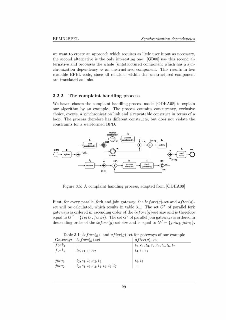
We haven chosen the complaint handling process model [ODHA08] to explainour algorithm by an example. The process contains concurrency, exclusivechoice, events, a synchronization link and a repeatable construct in terms of aloop. The process therefore has different constructs, but does not violate theconstraints for a well-formed BPD.
Figure 3.5: A complaint handling process, adapted from [ODHA08]
First, for every parallel fork and join gateway, the before(g)-set and after(g)-set will be calculated, which results in table 3.1. The set GF of parallel forkgateways is ordered in ascending order of the before(g)-set size and is thereforeequal to GF = {fork1, fork2}. The set GJ of parallel join gateways is ordered indescending order of the before(g)-set size and is equal to GJ = {join2, join1}.
Table 3.1: before(g)- and after(g)-set for gateways of our exampleGateway: before(g)-set after(g)-setfork1 − t2, e1, t3, e2, t4, t5, t6, t7
fork2 t2, e1, t3, e2 t4, t6, t7
join1 t2, e1, t3, e2, t5 t6, t7
join2 t2, e1, t3, e2, t4, t5, t6, t7 −
29
BPMN2BPEL Mapping BPMN to BPEL
There exists a direct relation between a parallel fork and join gateway whichsatisfies the condition on line 3 of the algorithm. Node fork1 is taken andwill be matched to join2 by the algorithm because of matching branch(g)-sets. Node fork2 will then be processed and can not be matched to an equalbranch(g)-set of a remaining join-gateway. Also branch(fork2) is not a subsetof branch(join1) and vice versa. Since the relation between fork2 and join1 isindeed a direct relation, it is marked as a synchronization link.
3.3 Dominators, loop headers and follow sets
Since synchronization links will be processed different from other relations inthis step, we first need to define an adjusted Business Process Diagram. Thisadjusted BPD is cleared from synchronization links and gateways might havebeen replaced by dummy nodes. The new set of relations FN is the set ofrelations excluding the elements in the synchronization links set FS , so FN =F\FS . Some gateways might transform into gateways with only one incomingand one outgoing arc, which conflicts with the definition of a well-formed BPD.By replacing these gateways with dummy tasks, the resulting BPD will bewell-formed again.
For finding structure in BPDs, some concepts like dominators, loop headersand follow-sets have been introduced. We adapted this section from Eshuis etal. [EG09]. Follow-sets can be calculated based on the dominators and loopheaders. The result is a description of the structured properties of the BPD.As we will see later on, these concepts can be used in our algorithm.
The concept of dominator is used to identify nesting structure and is takenfrom [EG09]. Let p be a node in O, q be a node in O and start be a node inES . Node p dominates node q if every path from start to q passes through pand this path is free of synchronization links:
p, q ∈ O, start ∈ ES , startFN *p ∧ pFN *q, i.e. every path from start to qpasses through p.
Every node except the start node has at least one dominator. Node p is theimmediate dominator of node q if every dominator of q other than p also dom-inates p. Let DOM(p) denote the immediate dominator of p. A node p canonly have one DOM(p) and therefore DOM(p) is unique for p [ASU86].
Next, loops need to be identified and loop headers need to be determined. Aloop is identified with the help of back edges. A back edge is an edge (x, y) inFN where y dominates x. The natural loop of a back edge can be computed,which is the set of nodes that can reach x without going through y, plus y.
30
BPMN2BPEL BPEL grammar
Node y is the header of the natural loop, which is defined as HEAD(n) = y.A node that is target of some back edge is called a loop node. If a node is nota loop node, it’s HEAD(n) is undefined.
When we both determined the dominators and loop headers of a BPD, wecan calculate the follow-sets. A follow-set of p contains all the nodes that areimmediately after p, at the same level of nesting, in the structured composition.
Definition 3. The follow-set of p, FOLLOW (P ), can be calculated with thefollowing rules:
For a fork node p, so p ∈ GF ∪ GD ∪ GV , let
FOLLOW (p) = { q | q ∈ GJ ∪ GM∧ p = DOM(q) ∧ HEAD(p) = HEAD(q) }
For a loop node p, so some back edge enters p, define
FOLLOW (p) = { q | DOM(q) is in a natural loop headed by p }
For each other node p, define
FOLLOW (p) = { q | HEAD(p) = HEAD(q) ∧ p = DOM(q) }
3.4 BPEL grammar
When we determined the synchronization links, dominators, loop headers andfollow sets, the necessary input for the algorithm is gathered. The algorithmwill result in a description of the BPEL process in the grammar presentedbelow. To keep the algorithm readable and comprehensible we haven chosenfor this grammar, adapted from Eshuis [EG09], instead of direct BPEL code tooutput. We also investigated a grammar based on process algebra presented by[BK05], but due to the restriction of the binary grammar we have chosen notto use this. In the end, a mapping between our grammar and the BPEL syntaxcan be used to generate BPEL code.
Let T be a set of tasks, ranged over by t, let E be a set of events, ranged overby e and let D be a set of dummy objects, ranged over by d. The language ofstructured processes, ranged over by P , is generated by the following grammar:
P ::= seq | and{seq, seq, .., seq, linkset} | xor{grdBseq, grdBseq, .., grdBseq}| repeat seq until grd | atomic
atomic ::= t | e | d
seq ::= < P,P, .., P >
grd ::= in(atomic) | grd ∨ grd | true
31

BPMN2BPEL Mapping BPMN to BPEL
linkset ::= {link(atomic, atomic), ..,link(atomic, atomic)}
The expression < P,P, .., P > indicates that the elements in the list are ex-ecuted one by one, according to the order specified in the list. Expressionand{seq, seq, .., seq, linkset} specifies that the elements in the set are executedin parallel and the branches can have multiple synchronization dependencieswhich are defined in linkset. Expression xor{grdBseq, grdBseq, .., grdBseq}specifies that exactly one of the guarded expressions in the set is executed,while repeat seq until grd specifies that expression seq is executed until con-dition grd holds. The guard in(atomic) is true if atomic was done previously.The linkset can contain multiple synchronization dependencies, which can bedefined as link(atomic, atomic). This indicates a synchronization dependencybetween two atomic elements, where the first element is the source of the syn-chronization link and the second element is the target. The target can only beprocessed when the link is activated by the source element. Both atomic ele-ments of a link-construct should be within the same scope, which is the lowestcommon ancestor and-construct.
3.5 The algorithm
3.5.1 Adjustment of the algorithm
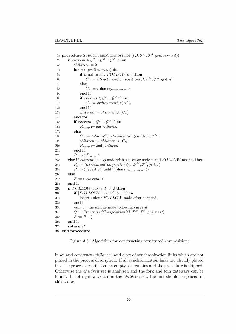
The structured composition algorithm adapted from Eshuis et al. [EG09] islisted in Figure 3.6. The algorithm is slightly adjusted to fit to the input pa-rameters of a well-formed BPD and to add synchronization links in the scopeof and-constructs. It requires as input a set O of objects, a set FN of relations,a set FS of synchronization links, a partial function grd that maps relations toguard expressions, and the node current that is to be processed. The algorithmneeds a well-formed BPD as input as explained earlier. For each fork a subse-quent join of the same type needs to be present. It is also possible that one forkbelongs to multiple joins or one join belongs to multiple forks, as long as theyhave the same type. All loops need a single entry gateway gentry ∈ GM and asingle exit gateway gexit ∈ GD ∪GV . Finally, it is required that parallelism doesnot cross the border of loops, because such behaviour cannot be expressed instructured processes.
The algorithm for finding synchronization links should be executed before thisstructured composition algorithm. This structured composition algorithm re-turns a sequential block that starts with current and is based on the BPELgrammar presented before. Further explanation of the algorithm is given in[EG09].
The procedure for adding a synchronization link is given in Figure 3.8. Thisprocedure is called from the algorithm of Eshuis and requires a set of objects
32
BPMN2BPEL The algorithm
1: procedure StructuredComposition((O,FN ,FS , grd, current))2: if current ∈ GF ∪ GD ∪ GV then3: children := ∅4: for n ∈ post(current) do5: if n not in any FOLLOW set then6: Cn := StructuredComposition(O,FN ,FS , grd, n)7: else8: Cn :=< dummycurrent,n >9: end if
10: if current ∈ GD ∪ GV then11: Cn := grd(current, n)BCn
12: end if13: children := children ∪ {Cn}14: end for15: if current ∈ GD ∪ GV then16: Pcomp := xor children17: else18: Cn := AddingSynchronization(children,FS)19: children := children ∪ {Cn}20: Pcomp := and children21: end if22: P :=< Pcomp >23: else if current is loop node with successor node x and FOLLOW node n then24: Px := StructuredComposition(O,FN ,FS , grd, x)25: P :=< repeat Px until in(dummycurrent,n) >26: else27: P :=< current >28: end if29: if FOLLOW (current) 6= ∅ then30: if |FOLLOW (current)| > 1 then31: insert unique FOLLOW node after current32: end if33: next := the unique node following current34: Q := StructuredComposition(O,FN ,FS , grd, next)35: P := P_Q36: end if37: return P38: end procedure
Figure 3.6: Algorithm for constructing structured compositions
in an and-construct (children) and a set of synchronization links which are notplaced in the process description. If all synchronization links are already placedinto the process description, an empty set remains and the procedure is skipped.Otherwise the children set is analyzed and the fork and join gateways can befound. If both gateways are in the children set, the link should be placed inthis scope.
33

BPMN2BPEL Mapping BPMN to BPEL
1: f := a fresh node not in O2: O := O ∪ {f}3: Efollows := { (x, y)|(x, y) ∈ FN ∧ x ∈ O ∧ y ∈ FOLLOW (current) }4: Enew := { (x, f), (f, y)|(x, y) ∈ Efollows }5: E := (FN \ Efollows) ∪ Enew
6: if current ∈ GD ∪ GV then7: grd := grd ∪ {(f, y) 7→ formulaPreCondition(y)|(x, y) ∈ Efollows}8: end if
Figure 3.7: Inserting unique FOLLOW node after current (l. 31 of Fig. 3.6)
Because this procedure is first called at the deepest level of nesting of an and-construct, the scope of the link is always as narrow as possible.
1: procedure AddingSynchronization((children,FS))2: if (FS = ∅) then3: return ∅4: else5: linkset := ∅6: for (f, j) ∈ FS do7: if f ∈ children ∧ j ∈ children then8: FS := FS\(f, j)9: linkset := linkset ∪ {link(f, j)}
10: end if11: end for12: return linkset13: end if14: end procedure
Figure 3.8: Adding synchronization dependencies to the block structure
3.5.2 The complaint handling process
To illustrate the algorithm as a whole, we will further process the translation ofthe BPMN model presented in 3.2.2. First the set of dominators, loop headersand follow sets is determined and is given in table 3.2. Note that we use the setFN of relations instead of F , since we do not want to process synchronizationlinks at this moment. We can see that each last node of a specific level ofnesting has an empty FOLLOW (n)-set, all other nodes have one element inthe FOLLOW (n)-set. A loop can be identified between the nodes xor3 andxor4.
With these concepts, the algorithm can be executed and results in a structuredcomposition. In Figure 3.9 we show this structured composition. In total, twodummy nodes have been added to support the loop in the structured model.Also the synchronization link detected earlier is added to the structured com-
34
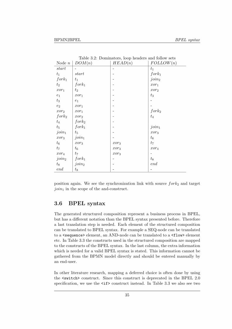
BPMN2BPEL BPEL syntax
Table 3.2: Dominators, loop headers and follow setsNode n DOM(n) HEAD(n) FOLLOW (n)start - - t1
t1 start - fork1
fork1 t1 - join2
t2 fork1 - xor1
xor1 t2 - xor2
e1 xor1 - t3
t3 e1 - -e2 xor1 - -xor2 xor1 - fork2
fork2 xor2 - t4
t4 fork2 -t5 fork1 - join1
join1 t5 - xor3
xor3 join1 - t6
t6 xor3 xor3 t7
t7 t6 xor3 xor4
xor4 t7 xor3 -join2 fork1 - t8
t8 join2 - endend t8 - -
position again. We see the synchronization link with source fork2 and targetjoin1 in the scope of the and-construct.
3.6 BPEL syntax
The generated structured composition represent a business process in BPEL,but has a different notation than the BPEL syntax presented before. Thereforea last translation step is needed. Each element of the structured compositioncan be translated to BPEL syntax. For example a SEQ-node can be translatedto a <sequence> element, an AND-node can be translated to a <flow> elementetc. In Table 3.3 the constructs used in the structured composition are mappedto the constructs of the BPEL syntax. In the last column, the extra informationwhich is needed for a valid BPEL syntax is stated. This information cannot begathered from the BPMN model directly and should be entered manually byan end-user.
In other literature research, mapping a deferred choice is often done by usingthe <switch> construct. Since this construct is deprecated in the BPEL 2.0specification, we use the <if> construct instead. In Table 3.3 we also see two
35

BPMN2BPEL Mapping BPMN to BPEL
possible implementations for the XOR-construct. If a race condition occurs be-tween multiple events, the choice of the event is modeled by a <pick> construct.When choice is not made based on events but on data, the <if> construct willbe used.
Table 3.3: Structured composition to BPEL syntaxStructuredcomposition BPEL construct Information neededtask <invoke> partnerLink, portType,
operationSEQ <sequence>AND <flow>XOR <if>, <condition> Condition
<elseif>, <condition> Condition<else><pick>
LOOP <repeatUntil> ConditionLINK <links>, <link> Name
<sources>, <source> linkName<targets>, <target> linkName
36

BPMN2BPEL BPEL syntax
Figure 3.9: The structured composition for the complaint handling process
37

BPMN2BPEL Mapping BPMN to BPEL
38
BPMN2BPEL 2
Chapter 4
An Eclipse plugin
The algorithm presented in chapter 3 is implemented as a plugin in the Eclipsedevelopment environment. We have chosen for this open source environmentbecause there already exists an implementation for translating BPMN to BPELby [GB08] and within Eclipse it is possible to model processes according to theBPMN standard.
4.1 Creating BPMN models in Eclipse
Before the translation from BPMN to BPEL can be developed, first a toolshould be available for modeling business processes in the BPMN standard.We have chosen for the plugin available for Eclipse because we are going to de-velop the translation process also in Eclipse. For modeling business processesaccording to the BPMN standard, the ‘STP BPMN modeler’ is needed. Thismodeler can be installed by installing the Eclipse plugins for ‘Graphical Edi-tors and Frameworks’, ‘Models and Model Development’ and the ‘STP BPMNmodeler’.
In Eclipse, a BPMN model can be drawn by selecting the needed constructsand connect them with arrows. In Figure 4.1 an example of a BPMN modeldrawn in Eclipse is given. However, the plugin does not check the model forcorrectness. A user can create an incorrect or incomplete model which can notbe translated by the algorithm. This restriction of the plugin should be takeninto account while creating models. The user must check the constraints of awell-formed BPD, which we mentioned before, by himself.
4.2 Running the algorithm
The algorithm discussed in chapter 3 is implemented by extending an existingimplementation by Eshuis. His implementation requires a dependency graph
39

BPMN2BPEL An Eclipse plugin
Figure 4.1: The BPMN modeling tool in Eclipse
represented by nodes and edges as input model and translates this to a struc-tured composition. In Figure 4.2 the plugin is described in a flow chart. Theimplementation follows the algorithm presented in [EG09] but has still somefunctionalities unimplemented like loop constructs. The existing implemen-tation generates a structured tree and eventually an ESML export. In ourimplementation, we will adjust both functionalities to BPEL generation.
Figure 4.2: Graphical flowchart how the plugin works
First the input requirement should be adjusted to require a BPMN model asinput instead of a dependency graph. The BPMN model should be analyzedand expressed in terms of nodes and edges. In this way, the BPMN model canbe seen as an extended type of a dependency graph. Therefore the currentimplementation can be reused and only needs some adjustments which will be
40

BPMN2BPEL Plugin evaluation
discussed later. To prevent loosing information about the BPMN model, extrainformation is added to the concept of a node. A node can have different typeslike a task, a parallel fork gateway etc.
A new algorithm which is implemented is the algorithm to find synchronizationdependencies. We presented this algorithm in Figure 3.4. The algorithm isimplemented as a function and searches for synchronization dependencies. Ifsynchronization dependencies are found, these edges are moved to a temporaryvariable. These edges are used again when the algorithm of Eshuis has beenexecuted and the structured process composition is generated.
Some functionalities are improved in the implementation. Loops for examplewere not covered in the way the algorithm of Eshuis described, but were parsedas sequences. We adjusted the implementation such that loops with one entryand one exit point are implemented according to the algorithm of Eshuis. Adummy node is inserted and the loop is repeated until the dummy node isexecuted. Some minor bugs we encountered during the adjustment are fixed andthe implementation is extended with the algorithm for finding synchronizationdependencies. User input in the implementation is not necessary anymore,since the function ’ask for feedback by unclearness’ can be replaced with theinformation available from the input model.
The structured composition, which is one of the generated results of the Eclipseplugin, is also exported in BPEL syntax. This BPEL syntax can be used byOracle’s BPEL Process Manager, which will be discussed later. To ensure validBPEL syntax, adding extra information is necessary. WSDL data needs to beadded for defining namespaces, partnerlinks, porttypes and possible variables.Currently, this information is hardcoded in the implementation.
The Eclipse plugin can be executed by running it from the commandline orrunning the program via Eclipse. The initial goal was to adjust the interfaceof the BPMN modeling tool such that the plugin is directly executed. Becauseof unforeseen problems we are not able to solve this issue. However, whenrunning the plugin via commandline with the filename of the BPMN model asargument, the plugin works fine. This small workaround is acceptable for ourmaster project.
4.3 Plugin evaluation
Development of the plugin was done according to the spiral model of BarryBoehm [Boe88]. First basic BPMN models must be mapped correctly to aBPEL process, then the algorithm for finding synchronization dependencies was
41
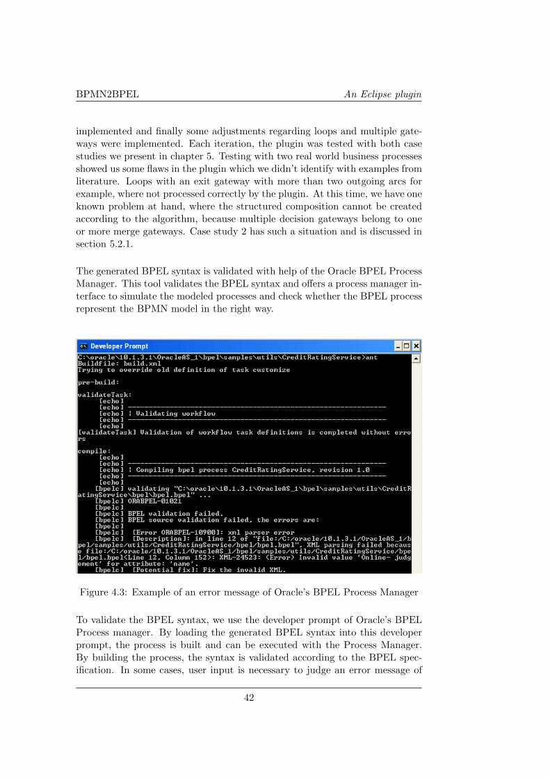
BPMN2BPEL An Eclipse plugin
implemented and finally some adjustments regarding loops and multiple gate-ways were implemented. Each iteration, the plugin was tested with both casestudies we present in chapter 5. Testing with two real world business processesshowed us some flaws in the plugin which we didn’t identify with examples fromliterature. Loops with an exit gateway with more than two outgoing arcs forexample, where not processed correctly by the plugin. At this time, we have oneknown problem at hand, where the structured composition cannot be createdaccording to the algorithm, because multiple decision gateways belong to oneor more merge gateways. Case study 2 has such a situation and is discussed insection 5.2.1.
The generated BPEL syntax is validated with help of the Oracle BPEL ProcessManager. This tool validates the BPEL syntax and offers a process manager in-terface to simulate the modeled processes and check whether the BPEL processrepresent the BPMN model in the right way.
Figure 4.3: Example of an error message of Oracle’s BPEL Process Manager
To validate the BPEL syntax, we use the developer prompt of Oracle’s BPELProcess manager. By loading the generated BPEL syntax into this developerprompt, the process is built and can be executed with the Process Manager.By building the process, the syntax is validated according to the BPEL spec-ification. In some cases, user input is necessary to judge an error message of
42
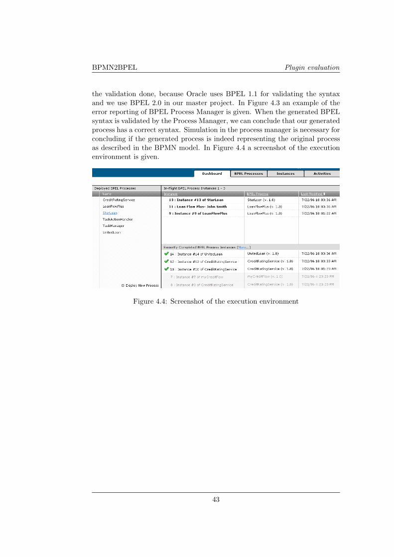
BPMN2BPEL Plugin evaluation
the validation done, because Oracle uses BPEL 1.1 for validating the syntaxand we use BPEL 2.0 in our master project. In Figure 4.3 an example of theerror reporting of BPEL Process Manager is given. When the generated BPELsyntax is validated by the Process Manager, we can conclude that our generatedprocess has a correct syntax. Simulation in the process manager is necessary forconcluding if the generated process is indeed representing the original processas described in the BPMN model. In Figure 4.4 a screenshot of the executionenvironment is given.
Figure 4.4: Screenshot of the execution environment
43

BPMN2BPEL An Eclipse plugin
44

BPMN2BPEL 2
Chapter 5
Case studies
In this chapter, we discuss two case studies which are gathered at Logica. Wewill describe the case studies, translate them from BPMN to BPEL manuallyaccording to the algorithm presented in chapter 3 and finally compare theseresults with the results of the developed plugin (chapter 4).
Both case studies are based on real business processes of financial companies inthe Netherlands. For reasons of confidentiality we are not mentioning the namesof these companies. In both situations, the software architecture used within thecompany has a high number of orchestration-layers. Each component invokesother services and uses the response for further processing. Such situationsmatch the purpose of BPEL and the case studies are therefore quite useful forevaluating our algorithm.
5.1 Loan request for an insurance company
Our first case study represents a loan request of a customer via a direct orintermediate channel. Both channels use the same underlying process. Afterthe request is received and saved in the database, the request is judged via anonline interface. This interface can respond with three different cases. Therequest can be accepted, declined or refered.
When a request needs to be refered, it can be due to a fraud suspicion, synonymsmisunderstanding or technical error. Depending on the reason, an activity isstarted to solve this issue or check for more information. With this information,the loan request can again be judged via the online interface.
If a loan request is accepted, the process will inform the customer and waitfor an acceptation. The accepted offer is processed further in concurrency; thecontract is prepared while documents are gathered. When all documents aregathered and processed, the contract is finished and the loan is provided.
45
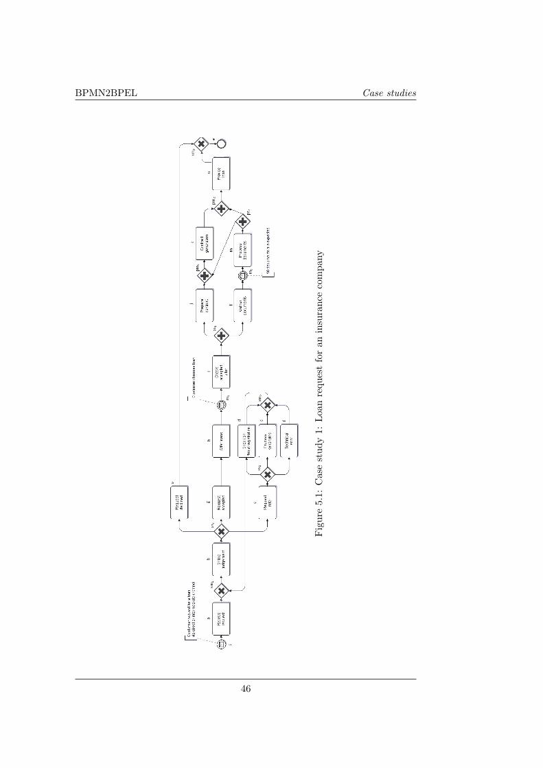
BPMN2BPEL Case studies
Fig
ure
5.1:
Cas
est
udy
1:L
oan
requ
est
for
anin
sura
nce
com
pany
46
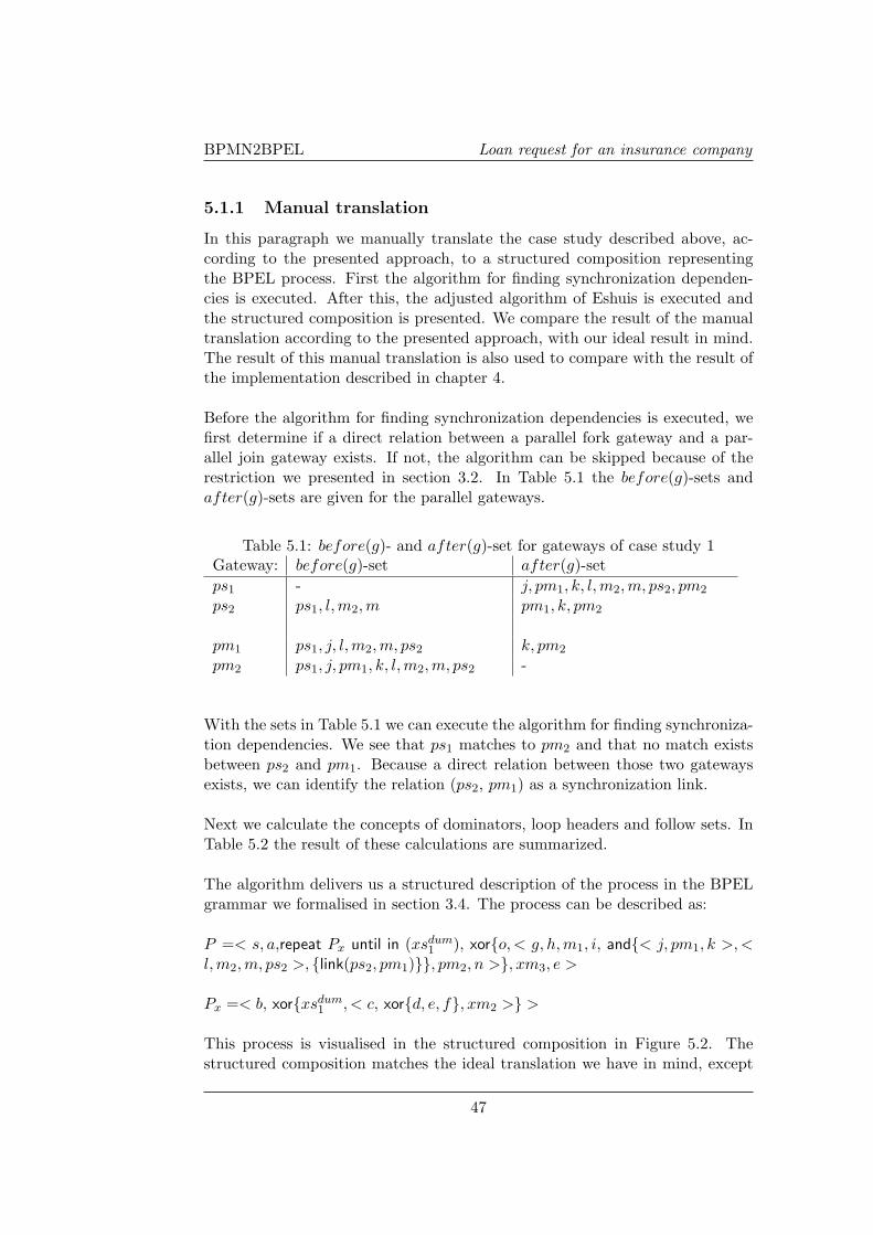
BPMN2BPEL Loan request for an insurance company
5.1.1 Manual translation
In this paragraph we manually translate the case study described above, ac-cording to the presented approach, to a structured composition representingthe BPEL process. First the algorithm for finding synchronization dependen-cies is executed. After this, the adjusted algorithm of Eshuis is executed andthe structured composition is presented. We compare the result of the manualtranslation according to the presented approach, with our ideal result in mind.The result of this manual translation is also used to compare with the result ofthe implementation described in chapter 4.
Before the algorithm for finding synchronization dependencies is executed, wefirst determine if a direct relation between a parallel fork gateway and a par-allel join gateway exists. If not, the algorithm can be skipped because of therestriction we presented in section 3.2. In Table 5.1 the before(g)-sets andafter(g)-sets are given for the parallel gateways.
Table 5.1: before(g)- and after(g)-set for gateways of case study 1Gateway: before(g)-set after(g)-setps1 - j, pm1, k, l, m2, m, ps2, pm2
ps2 ps1, l, m2, m pm1, k, pm2
pm1 ps1, j, l,m2, m, ps2 k, pm2
pm2 ps1, j, pm1, k, l, m2, m, ps2 -
With the sets in Table 5.1 we can execute the algorithm for finding synchroniza-tion dependencies. We see that ps1 matches to pm2 and that no match existsbetween ps2 and pm1. Because a direct relation between those two gatewaysexists, we can identify the relation (ps2, pm1) as a synchronization link.
Next we calculate the concepts of dominators, loop headers and follow sets. InTable 5.2 the result of these calculations are summarized.
The algorithm delivers us a structured description of the process in the BPELgrammar we formalised in section 3.4. The process can be described as:
P =< s, a,repeat Px until in (xsdum1 ), xor{o, < g, h, m1, i, and{< j, pm1, k >, <
l,m2, m, ps2 >, {link(ps2, pm1)}}, pm2, n >}, xm3, e >
Px =< b, xor{xsdum1 , < c, xor{d, e, f}, xm2 >} >
This process is visualised in the structured composition in Figure 5.2. Thestructured composition matches the ideal translation we have in mind, except
47

BPMN2BPEL Case studies
Table 5.2: Dominators, loop headers and follow sets for case study 1Object (O) DOM(O) HEAD(O) FOLLOW (O)s − − aa s − xm1
xm1 a Loopheader xsdum1
b xm1 xm1 xs1
xs1 b xm1 cc xs1 xm1 xs2
xs2 c xm1 xm2
d xs2 xm1 −e xs2 xm1 −f xs2 xm1 −xm2 xs2 xm1 xm1
g xsdum1 − h
h g − m1
m1 h − ii m1 − ps1
ps1 i − pm2
j ps1 − pm1
pm1 j − kk pm1 − −l ps1 − m2
m2 l − mm m2 − ps2
ps2 m − −pm2 ps1 − nn pm2 − −o xsdum
1 − −xm3 xsdum
1 − ee xm3 − −
for the merge-gateways. These gateways are not needed in the structured com-position, because they do not represent an activity. For Figure 5.2, the nodesxm2, pm2 and xm3 can be removed.
5.1.2 Translating via the plugin
When we translate the same case study with the plugin we developed, a struc-tured composition tree given in Figure 5.4 is generated. This tree is similarto the graphical structured composition of the manual composition, except forsome elements which represent the join or merge gateways. Some of these tasksare eliminated in the plugin, since they do not represent a real activity. Thereis some future work in removing these gateways, since not all gateways are re-
48
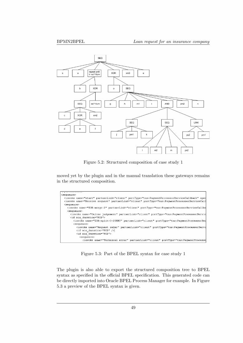
BPMN2BPEL Loan request for an insurance company
Figure 5.2: Structured composition of case study 1
moved yet by the plugin and in the manual translation these gateways remainsin the structured composition.
Figure 5.3: Part of the BPEL syntax for case study 1
The plugin is also able to export the structured composition tree to BPELsyntax as specified in the official BPEL specification. This generated code canbe directly imported into Oracle BPEL Process Manager for example. In Figure5.3 a preview of the BPEL syntax is given.
49

BPMN2BPEL Case studies
Figure 5.4: Structured composition tree of case study 1
50
BPMN2BPEL Total credit risk calculation
5.2 Total credit risk calculation
Our second case study represents the process of a total credit risk calculation.The process is adapted from an insurance company which is a client of Logica.The process represents an orchestration layer between the end-user applicationsand functional services which are implemented in the software architecture ofthe company. In Figure 5.5 the BPMN model of this orchestration layer isgiven.
A request for a credit risk calculation is done by a customer or an insuranceagency. After this request, some activities are invoked in sequence. First theinternal activity 48A.1 is invoked and the policy restrictions are checked byanother invocation. A quick financial check is then executed. The result of thischeck is evaluated to determine if all necessary information is obtained. If not,an extended check is performed and evaluated again. This loop continues untilall necessary information is obtained.
The complete set of information is then evaluated and the process determinesthe risk on fraud. In case of a high risk on fraud, the process returns an errorto the initiator of the process. In other cases, the orchestration layer invokesmore internal activities and then performs a credit check. Both the service‘AutoBKR’ and ‘SynonymsBKR’ are invoked in parallel. The results of bothservices are combined and interpreted when both services are finished. Internalactivity 48A.5 evaluates this interpretation and decides if more checks need tobe executed or a result can already be given to internal activity 48A.10.
In case more checks need to be executed, a scenario is determined and handledconcurrently by two other processes. The credit score and the max loan capacityare calculated. After calculating the credit score, a score card needs to bedecided, but this can only be done when the max loan capacity is also known.Therefore a synchronization link is introduced in the model. The result isdetermined for the scenario and the process might be terminated because ofan error message, or the total results are calculated and processed as eitheran error or a positive result. The positive result will be processed further byinternal activity 48A.10 and will be returned to the initiator of the process.
51

BPMN2BPEL Case studies
Fig
ure
5.5:
Cas
est
udy
2:to
tal
cred
itri
skca
lcul
atio
n
52

BPMN2BPEL Total credit risk calculation
5.2.1 Manual translation
In this paragraph we manually translate the case study described above to astructured composition representing the BPEL process. First the algorithm forfinding synchronization dependencies is executed. After this, the adjusted algo-rithm of Eshuis is executed and the structured composition is presented. Againwe compare the result of the manual translation according to the presented ap-proach, with our ideal result in mind. The result of this manual translation isalso used to compare with the result of the implementation described in chapter4.
Before the algorithm for finding synchronization dependencies is executed, wefirst determine if a direct relation between a parallel fork gateway and a par-allel join gateway exists. If not, the algorithm can be skipped because of therestriction we presented in section 3.2. In Table 5.3 the before(g)-sets andafter(g)-sets are given for the parallel gateways.
Table 5.3: before(g)- and after(g)-set for gateways of case study 2Gateway: before(g)-set after(g)-setps1 - i, j, pm1
ps2 - o, pm2, p, q, ps3, pm3
ps3 ps2, q pm2, p, pm3
pm1 ps1, i, j -pm2 ps2, o, q, ps3 p, pm3
pm3 ps2, o, pm2, p, q, ps3 -
With the sets in Table 5.3 we can execute the algorithm for finding synchro-nization dependencies. We see that ps1 matches to pm1, ps2 matches to pm3
and that no match exists between ps3 and pm2. Because a direct relation be-tween those two gateways exists, we can identify the relation (ps3, pm2) as asynchronization link.Next we calculate the concepts of dominators, loop headers and follow sets. InTable 5.4 the result of these calculations are summarized. The algorithm deliv-ers a structured description of the process in the BPEL grammar we formalisedin section 3.4. The process can be described as:
P =< s, a, b, c,repeat Px until in (xsdum1 ), f, xor{Py, xsdum
2 }, xm2, y, xm4, e >
Px =< d, xor{e, xsdum1 } >
Py =< g, h, and{i, j}, pm1, k, l, xor{Pz}, xm3, w >Pz =< xsdum
3 , < m, n, and{< o, pm2, p >, < q, ps3 >, {link(ps3, pm2)}}, pm3, r, s,xor{xsdum
4 , < t, u, v, xor{xsdum15 , xsdum2
5 } >} >>
53

BPMN2BPEL Case studies
Table 5.4: Dominators, loop headers and follow sets for case study 2Obj. DOM HEAD FOLLOW Obj. DOM HEAD FOLLOW(O) (O) (O) (O) (O) (O) (O) (O)s - a ps2 n pm3
a s b o ps2 pm2
b a c pm2 o pc b xm1 p pm2 −xm1 c loopnode f q ps2 ps3
d xm1 xm1 xs1 ps3 q −xs1 d xm1 − pm3 ps2 re xs1 xm1 − r pm3 sf xs1 xs2 s r xs4
xs2 f xm2; xm4 xs4 s −g xs2 h t xs4 uh g ps1 u t vps1 h pm1 v u xs5
i ps1 − xs5 v −j ps1 − xm2 xs2 ypm1 ps1 k xm3 xs3 wk pm1 l w xm3 −l k xs3 y xm2 −xs3 l xm3 xm4 xs2 em xs3 n e xm4 −n m ps2
This process is visualised in the structured composition in Figure 5.6. Thestructured composition matches the ideal translation we have in mind globally,except for the merge-gateways. The merge-gateways are not needed in thestructured composition, because they do not represent an activity. For Figure5.6, the nodes pm1, pm3, xm2, xm3 and xm4 can be removed.
5.2.2 Translating via the plugin
Translating the second case study via the plugin was more difficult than for thefirst case study. Problems occured when processing the xm2 decision gateway.Both the algorithm and the plugin must be improved at this point, which wesuggest as future work. In Figure 5.8 the structured composition which iscurrently the result of the mapping is given. This result should be improvedon two aspects. First the synchronization dependency algorithm must only beexecuted within one SESE-region and finally decision and merge gateways mustbe investigated and improved.
54

BPMN2BPEL Total credit risk calculation
Figure 5.6: Structured composition of case study 2
Figure 5.7: Part of the BPEL syntax for case study 2
The plugin is also able to export the structured composition tree to BPEL syn-tax as specified in the official BPEL specification. This generated code matchesthe generated structured composition and therefore has the same problems as
55
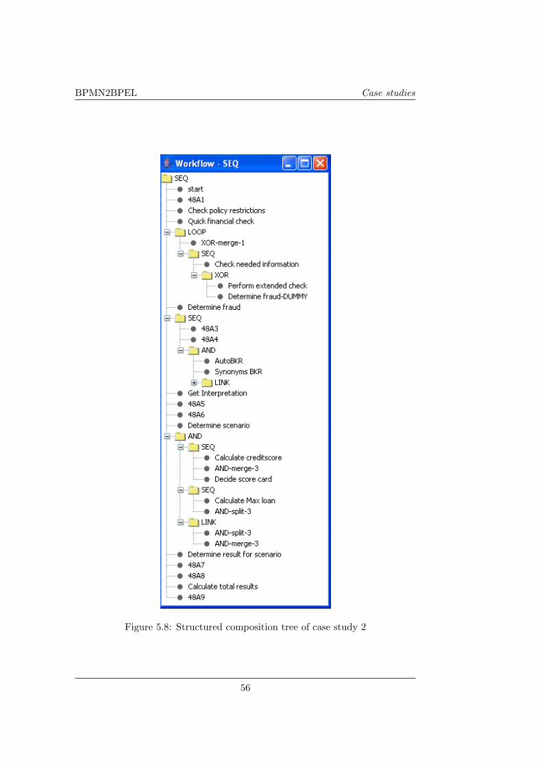
BPMN2BPEL Case studies
Figure 5.8: Structured composition tree of case study 2
56
BPMN2BPEL Conclusion
the translation to the structured composition. In Figure 5.7 a part of the BPELsyntax is given.
5.3 Conclusion
The purpose of introducing two case studies is the evaluation of both our al-gorithm and the implementation in Eclipse. The first case study was knownat forehand and is used during the development of the mapping discussed inchapter 3. The second case study is used after we described the mapping, butresulted in some adjustments to our algorithm. An example of such an adjust-ment is the extension of the algorithm for finding synchronization dependencieswith so called SESE-regions.
We also discovered that our implementation currently has some differences withthe algorithm in the field of multiple subsequent decision and merge gateways.A manual translation of the case study results in a corresponding BPEL model,but a translation via the plugin has some issues as described in the section ofcase study 2.
We can conclude that our algorithm can generate BPEL models from inputBPMN models which satisfy the restrictions of a well-formed BPD. In chapter6 we evaluate these restrictions and will see that some of the restrictions canbe relaxed.
57

BPMN2BPEL Case studies
58
BPMN2BPEL 2
Chapter 6
Evaluation of the mapping
In this chapter, we will evaluate our own mapping presented in chapter 3. Wewill discuss the strengths and weaknesses of the presented mapping and alsothe relation with other strategies and implementations. Because our algorithmuses a well-formed BPD as inputmodel, we will evaluate the restrictions of awell-formed BPD to investigate if we can also process more unstructured inputmodels. In the last section of this chapter, we will propose some future workfor our own algorithm based on the evaluation done.
We wanted to extend an existing algorithm presented by Rik Eshuis to make itsuitable for mapping BPMN to BPEL. In chapter 2 we discussed different strate-gies and concluded that combining the strengths of different approaches wouldresult in the best mapping. The developed algorithm works with structuredcomponents, but can also identify relations as synchronization dependencies.Control links, which are the main constructs of other strategies, are used onlywhen this is most appropriate. The existing algorithm presented by Rik Eshuisis adjusted to make it suitable for mapping most BPMN models to BPEL andimplemented as a plugin for Eclipse.
6.1 Strengths & Weaknesses
In chapter 2 we evaluated different strategies and mentioned some strengthsand weaknesses of each approach. In section 6.2 we will compare our approachwith these strategies. Before we can compare our own approach with thesestrategies, we will discuss the main strengths and weaknesses of our approachpresented in chapter 3.
Our approach supports input models with non-structured components, exceptfor arbitrary cycles. Not only structured input models can be processed, butalso unstructured models which satisfy the well-formedness restrictions of aBPD can be processed. The approach can deal with all parallel gateways and
59
BPMN2BPEL Evaluation of the mapping
decision gateways with arbitrary topology, however the implemented Eclipseplugin still has some problems with these situations. The generated BPELmodel is comprehensible and readable because it is largely structure based. Thegenerated BPEL is extended with synchronization dependencies, which are alsocomprehensible as long as they are only used for synchronization purposes.
Our approach consists of different steps like preprocessing, calculating conceptsas the immediate dominator, the original algorithm and the mapping to theBPEL syntax. These different steps make it more difficult to implement theapproach in a plugin for example. The plugin which we developed during ourmaster project has still some issues. Trivial models are mapped correctly, butcomplex models can result in some errors. Manual translation does not havethese problems and results in a correct BPEL model.
Another important issue is the presence of merge gateways. In the originalalgorithm of Rik Eshuis, no separate merge gateways exist, since these arecombined with normal tasks. As a result, these merge gateways are processedas tasks in our approach and cause unnecessary ’empty’ BPEL constructs. Theimplementation can easily be adjusted to filter these merge gateways, but thealgorithm should also be adjusted.
6.2 Relation with other strategies/implementations
First, we want to compare our own approach with the strategies mentioned inchapter 2. Our own approach scores better on readability than the link-basedor event-based approaches. Since the structured components are translated totheir subsequent BPEL constructs, the generated BPEL model can be main-tained a lot easier. Also the concept of a repeatable construct like a loop isnot supported in pure link-based strategies. Structure-based and event-basedstrategies do cover this construct. Our implementation also support loops witha single entry and a single exit point. Compared with structure-based strate-gies, our approach requires input models with less constraints and supportsunstructured models.
We also want to compare our approach and implementation with the twoopensource implementations mentioned in chapter 2, the BABEL-tool and theBPMN 2 BPEL Eclipse plugin. The BABEL-tool is not maintained anymore,but is an implementation often discussed in literature. The Eclipse plugin isa newly developed implementation, based on the global ideas of the BABEL-tool, but improved with SESE-regions. Both existing implementations and ourown implementation generate BPEL models with a high level of readability,since they all identify structured blocks first. All implementations support
60
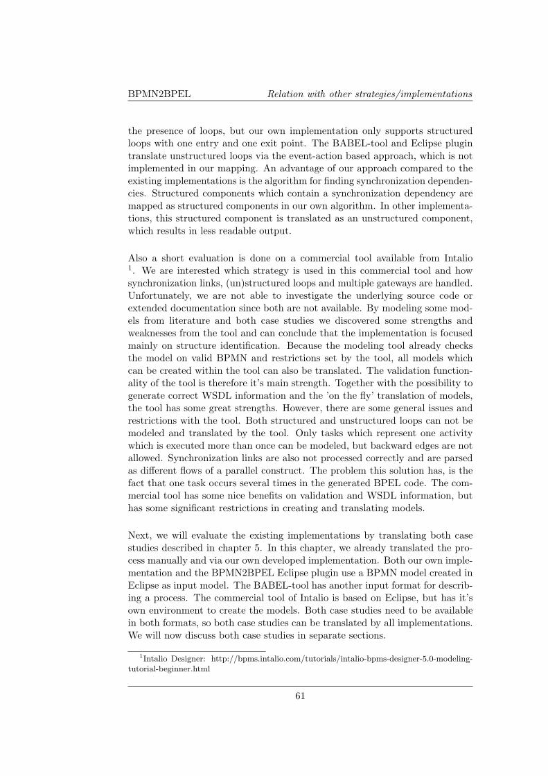
BPMN2BPEL Relation with other strategies/implementations
the presence of loops, but our own implementation only supports structuredloops with one entry and one exit point. The BABEL-tool and Eclipse plugintranslate unstructured loops via the event-action based approach, which is notimplemented in our mapping. An advantage of our approach compared to theexisting implementations is the algorithm for finding synchronization dependen-cies. Structured components which contain a synchronization dependency aremapped as structured components in our own algorithm. In other implementa-tions, this structured component is translated as an unstructured component,which results in less readable output.
Also a short evaluation is done on a commercial tool available from Intalio1. We are interested which strategy is used in this commercial tool and howsynchronization links, (un)structured loops and multiple gateways are handled.Unfortunately, we are not able to investigate the underlying source code orextended documentation since both are not available. By modeling some mod-els from literature and both case studies we discovered some strengths andweaknesses from the tool and can conclude that the implementation is focusedmainly on structure identification. Because the modeling tool already checksthe model on valid BPMN and restrictions set by the tool, all models whichcan be created within the tool can also be translated. The validation function-ality of the tool is therefore it’s main strength. Together with the possibility togenerate correct WSDL information and the ’on the fly’ translation of models,the tool has some great strengths. However, there are some general issues andrestrictions with the tool. Both structured and unstructured loops can not bemodeled and translated by the tool. Only tasks which represent one activitywhich is executed more than once can be modeled, but backward edges are notallowed. Synchronization links are also not processed correctly and are parsedas different flows of a parallel construct. The problem this solution has, is thefact that one task occurs several times in the generated BPEL code. The com-mercial tool has some nice benefits on validation and WSDL information, buthas some significant restrictions in creating and translating models.
Next, we will evaluate the existing implementations by translating both casestudies described in chapter 5. In this chapter, we already translated the pro-cess manually and via our own developed implementation. Both our own imple-mentation and the BPMN2BPEL Eclipse plugin use a BPMN model created inEclipse as input model. The BABEL-tool has another input format for describ-ing a process. The commercial tool of Intalio is based on Eclipse, but has it’sown environment to create the models. Both case studies need to be availablein both formats, so both case studies can be translated by all implementations.We will now discuss both case studies in separate sections.
1Intalio Designer: http://bpms.intalio.com/tutorials/intalio-bpms-designer-5.0-modeling-tutorial-beginner.html
61
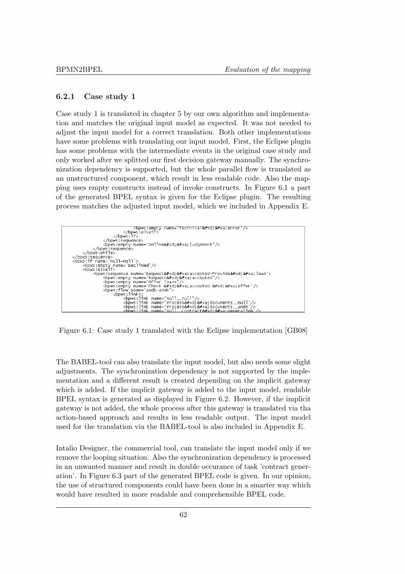
BPMN2BPEL Evaluation of the mapping
6.2.1 Case study 1
Case study 1 is translated in chapter 5 by our own algorithm and implementa-tion and matches the original input model as expected. It was not needed toadjust the input model for a correct translation. Both other implementationshave some problems with translating our input model. First, the Eclipse pluginhas some problems with the intermediate events in the original case study andonly worked after we splitted our first decision gateway manually. The synchro-nization dependency is supported, but the whole parallel flow is translated asan unstructured component, which result in less readable code. Also the map-ping uses empty constructs instead of invoke constructs. In Figure 6.1 a partof the generated BPEL syntax is given for the Eclipse plugin. The resultingprocess matches the adjusted input model, which we included in Appendix E.
Figure 6.1: Case study 1 translated with the Eclipse implementation [GB08]
The BABEL-tool can also translate the input model, but also needs some slightadjustments. The synchronization dependency is not supported by the imple-mentation and a different result is created depending on the implicit gatewaywhich is added. If the implicit gateway is added to the input model, readableBPEL syntax is generated as displayed in Figure 6.2. However, if the implicitgateway is not added, the whole process after this gateway is translated via thaaction-based approach and results in less readable output. The input modelused for the translation via the BABEL-tool is also included in Appendix E.
Intalio Designer, the commercial tool, can translate the input model only if weremove the looping situation. Also the synchronization dependency is processedin an unwanted manner and result in double occurance of task ’contract gener-ation’. In Figure 6.3 part of the generated BPEL code is given. In our opinion,the use of structured components could have been done in a smarter way whichwould have resulted in more readable and comprehensible BPEL code.
62
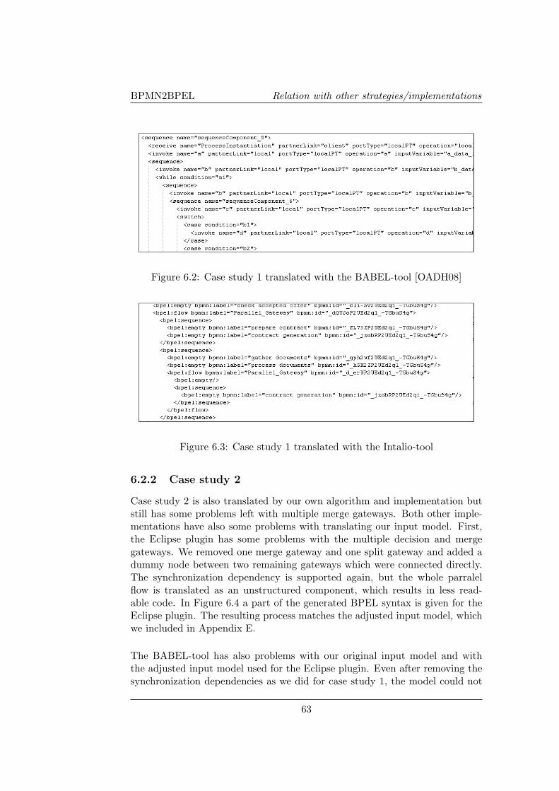
BPMN2BPEL Relation with other strategies/implementations
Figure 6.2: Case study 1 translated with the BABEL-tool [OADH08]
Figure 6.3: Case study 1 translated with the Intalio-tool
6.2.2 Case study 2
Case study 2 is also translated by our own algorithm and implementation butstill has some problems left with multiple merge gateways. Both other imple-mentations have also some problems with translating our input model. First,the Eclipse plugin has some problems with the multiple decision and mergegateways. We removed one merge gateway and one split gateway and added adummy node between two remaining gateways which were connected directly.The synchronization dependency is supported again, but the whole parralelflow is translated as an unstructured component, which results in less read-able code. In Figure 6.4 a part of the generated BPEL syntax is given for theEclipse plugin. The resulting process matches the adjusted input model, whichwe included in Appendix E.
The BABEL-tool has also problems with our original input model and withthe adjusted input model used for the Eclipse plugin. Even after removing thesynchronization dependencies as we did for case study 1, the model could not
63

BPMN2BPEL Evaluation of the mapping
Figure 6.4: Case study 2 translated with the Eclipse implementation [GB08]
be translated. By debugging the input model, we found that the cause of theproblem can be found in the parallel flow construct.
Intalio Designer can correctly translate the BPMN model, except for the loopconstruct and the synchronization dependencies. No problems occur with themultiple subsequent decision and merge gateways. The only serious issue whichwe already mentioned is the occurrence of the same task in the generated BPELmore than once. In Figure 6.5 a preview of the generated BPEL is given.
Figure 6.5: Case study 2 translated with the Intalio-tool
6.2.3 Conclusion
In Table 6.1 we summarize the evaluation in a table with the same componentsas the tabel presented in section 2.4. The BABEL-tool is not maintained any-more and the Eclipse plugin is a new implementation based on [GB08] whichdeals with the deterministic issues from the BABEL-tool discussed in chapter2. However, the Eclipse plugin should use a synchronization dependency al-
64
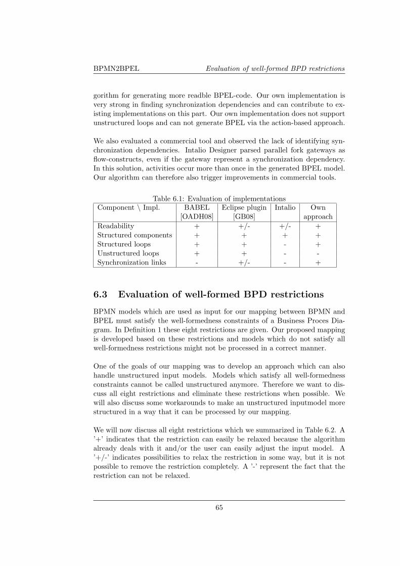
BPMN2BPEL Evaluation of well-formed BPD restrictions
gorithm for generating more readble BPEL-code. Our own implementation isvery strong in finding synchronization dependencies and can contribute to ex-isting implementations on this part. Our own implementation does not supportunstructured loops and can not generate BPEL via the action-based approach.
We also evaluated a commercial tool and observed the lack of identifying syn-chronization dependencies. Intalio Designer parsed parallel fork gateways asflow-constructs, even if the gateway represent a synchronization dependency.In this solution, activities occur more than once in the generated BPEL model.Our algorithm can therefore also trigger improvements in commercial tools.
Table 6.1: Evaluation of implementationsComponent \ Impl. BABEL Eclipse plugin Intalio Own
[OADH08] [GB08] approachReadability + +/- +/- +Structured components + + + +Structured loops + + - +Unstructured loops + + - -Synchronization links - +/- - +
6.3 Evaluation of well-formed BPD restrictions
BPMN models which are used as input for our mapping between BPMN andBPEL must satisfy the well-formedness constraints of a Business Proces Dia-gram. In Definition 1 these eight restrictions are given. Our proposed mappingis developed based on these restrictions and models which do not satisfy allwell-formedness restrictions might not be processed in a correct manner.
One of the goals of our mapping was to develop an approach which can alsohandle unstructured input models. Models which satisfy all well-formednessconstraints cannot be called unstructured anymore. Therefore we want to dis-cuss all eight restrictions and eliminate these restrictions when possible. Wewill also discuss some workarounds to make an unstructured inputmodel morestructured in a way that it can be processed by our mapping.
We will now discuss all eight restrictions which we summarized in Table 6.2. A’+’ indicates that the restriction can easily be relaxed because the algorithmalready deals with it and/or the user can easily adjust the input model. A’+/-’ indicates possibilities to relax the restriction in some way, but it is notpossible to remove the restriction completely. A ’-’ represent the fact that therestriction can not be relaxed.
65
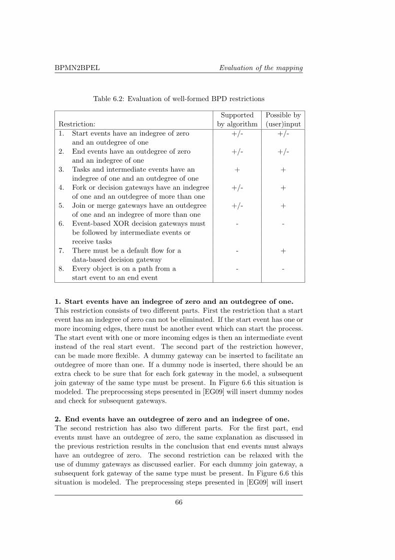
BPMN2BPEL Evaluation of the mapping
Table 6.2: Evaluation of well-formed BPD restrictions
Supported Possible byRestriction: by algorithm (user)input1. Start events have an indegree of zero +/- +/-
and an outdegree of one2. End events have an outdegree of zero +/- +/-
and an indegree of one3. Tasks and intermediate events have an + +
indegree of one and an outdegree of one4. Fork or decision gateways have an indegree +/- +
of one and an outdegree of more than one5. Join or merge gateways have an outdegree +/- +
of one and an indegree of more than one6. Event-based XOR decision gateways must - -
be followed by intermediate events orreceive tasks
7. There must be a default flow for a - +data-based decision gateway
8. Every object is on a path from a - -start event to an end event
1. Start events have an indegree of zero and an outdegree of one.This restriction consists of two different parts. First the restriction that a startevent has an indegree of zero can not be eliminated. If the start event has one ormore incoming edges, there must be another event which can start the process.The start event with one or more incoming edges is then an intermediate eventinstead of the real start event. The second part of the restriction however,can be made more flexible. A dummy gateway can be inserted to facilitate anoutdegree of more than one. If a dummy node is inserted, there should be anextra check to be sure that for each fork gateway in the model, a subsequentjoin gateway of the same type must be present. In Figure 6.6 this situation ismodeled. The preprocessing steps presented in [EG09] will insert dummy nodesand check for subsequent gateways.
2. End events have an outdegree of zero and an indegree of one.The second restriction has also two different parts. For the first part, endevents must have an outdegree of zero, the same explanation as discussed inthe previous restriction results in the conclusion that end events must alwayshave an outdegree of zero. The second restriction can be relaxed with theuse of dummy gateways as discussed earlier. For each dummy join gateway, asubsequent fork gateway of the same type must be present. In Figure 6.6 thissituation is modeled. The preprocessing steps presented in [EG09] will insert
66
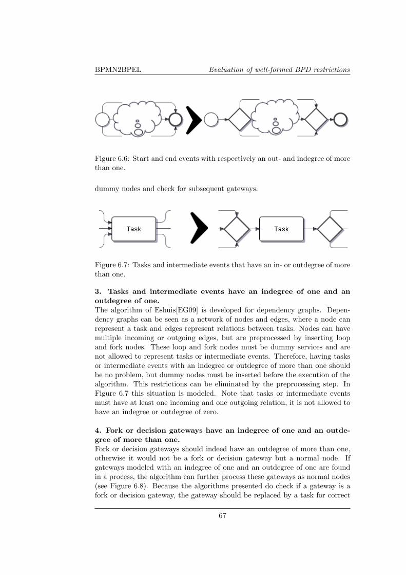
BPMN2BPEL Evaluation of well-formed BPD restrictions
Figure 6.6: Start and end events with respectively an out- and indegree of morethan one.
dummy nodes and check for subsequent gateways.
Figure 6.7: Tasks and intermediate events that have an in- or outdegree of morethan one.
3. Tasks and intermediate events have an indegree of one and anoutdegree of one.The algorithm of Eshuis[EG09] is developed for dependency graphs. Depen-dency graphs can be seen as a network of nodes and edges, where a node canrepresent a task and edges represent relations between tasks. Nodes can havemultiple incoming or outgoing edges, but are preprocessed by inserting loopand fork nodes. These loop and fork nodes must be dummy services and arenot allowed to represent tasks or intermediate events. Therefore, having tasksor intermediate events with an indegree or outdegree of more than one shouldbe no problem, but dummy nodes must be inserted before the execution of thealgorithm. This restrictions can be eliminated by the preprocessing step. InFigure 6.7 this situation is modeled. Note that tasks or intermediate eventsmust have at least one incoming and one outgoing relation, it is not allowed tohave an indegree or outdegree of zero.
4. Fork or decision gateways have an indegree of one and an outde-gree of more than one.Fork or decision gateways should indeed have an outdegree of more than one,otherwise it would not be a fork or decision gateway but a normal node. Ifgateways modeled with an indegree of one and an outdegree of one are foundin a process, the algorithm can further process these gateways as normal nodes(see Figure 6.8). Because the algorithms presented do check if a gateway is afork or decision gateway, the gateway should be replaced by a task for correct
67
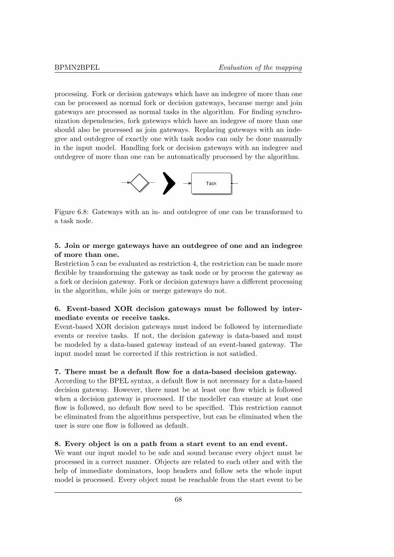
BPMN2BPEL Evaluation of the mapping
processing. Fork or decision gateways which have an indegree of more than onecan be processed as normal fork or decision gateways, because merge and joingateways are processed as normal tasks in the algorithm. For finding synchro-nization dependencies, fork gateways which have an indegree of more than oneshould also be processed as join gateways. Replacing gateways with an inde-gree and outdegree of exactly one with task nodes can only be done manuallyin the input model. Handling fork or decision gateways with an indegree andoutdegree of more than one can be automatically processed by the algorithm.
Figure 6.8: Gateways with an in- and outdegree of one can be transformed toa task node.
5. Join or merge gateways have an outdegree of one and an indegreeof more than one.Restriction 5 can be evaluated as restriction 4, the restriction can be made moreflexible by transforming the gateway as task node or by process the gateway asa fork or decision gateway. Fork or decision gateways have a different processingin the algorithm, while join or merge gateways do not.
6. Event-based XOR decision gateways must be followed by inter-mediate events or receive tasks.Event-based XOR decision gateways must indeed be followed by intermediateevents or receive tasks. If not, the decision gateway is data-based and mustbe modeled by a data-based gateway instead of an event-based gateway. Theinput model must be corrected if this restriction is not satisfied.
7. There must be a default flow for a data-based decision gateway.According to the BPEL syntax, a default flow is not necessary for a data-baseddecision gateway. However, there must be at least one flow which is followedwhen a decision gateway is processed. If the modeller can ensure at least oneflow is followed, no default flow need to be specified. This restriction cannotbe eliminated from the algorithms perspective, but can be eliminated when theuser is sure one flow is followed as default.
8. Every object is on a path from a start event to an end event.We want our input model to be safe and sound because every object must beprocessed in a correct manner. Objects are related to each other and with thehelp of immediate dominators, loop headers and follow sets the whole inputmodel is processed. Every object must be reachable from the start event to be
68

BPMN2BPEL Future work
able to calculate these concepts. Also every object must be on a path to anend event, to prevent deadlock situations. Therefore this restriction cannot bereleased.
As we can see, most restrictions can be relaxed by introducing some prepro-cessing steps. Inserting dummy nodes and possibly transforming gateways totasks or other gateways make some restrictions more flexible. Because calcula-tions are based on models which are well-formed, we need the introduction ofthese preprocessing steps, since these steps transform an unstructured processmodel to a well-formed BPD. The modeller only must ensure at least one flowis followed in case of a data-based decision gateway.
6.4 Future work
In this chapter we evaluated our mapping presented in chapter 3. We have seenthat some well-formed BPD restrictions can be relaxed and there is still somework left in the field of unstructured loops. The event-condition action-rulesbased approach presented by Mendling et al. might be implemented to be ableto handle unstructured loops. Both the BABEL-tool and Eclipse plugin havesuch an approach implemented. The problem we currently encounter in theimplementation (not in the algorithm) regarding multiple decision and mergegateways should also be investigated further for a stable implementation.
Another possible extension to the implementation is the data perspective. Inour research, we left this aspect out of scope, since the data object in BPMN iscurrently only a representation of an object. There are no rules about the dataitself.
69

BPMN2BPEL Evaluation of the mapping
70
BPMN2BPEL 2
Chapter 7
Conclusions
In this final chapter we summarize our findings by answering the research ques-tions defined in the introduction of this thesis. After doing this we cover somegeneral threats to the validity of the conclusions and give some suggestions forfuture work.
7.1 Answers to the research questions
In this section we will answer the research questions using the conclusions andanswers given in the other chapters of this thesis. The first research questioncan be answered using the results from the literature research, while the othertwo research questions can be answered using the results of our own mappingand the evaluation of the mapping by discussing the case studies.
7.1.1 What is the state-of-the-art with respect to BPMN andBPEL?
We have seen that both BPMN and BPEL are relatively new languages whichare still under development. In our research we focused on BPMN 1.1 andBPEL 2.0, which means that some examples from literature are not relevantanymore because they use BPEL 1.0 constructs which are deprecated. Newfeatures and possibilities that BPMN 2.0 will bring us, are not used becausethey are still in a draft status.
In the last few years, a lot of research has been done in the field of map-ping BPMN to BPEL. Different strategies and implementations arose, eachwith its own strengths and weaknesses. Three main categories can be stated:structured-based, link-based and event-action based strategies. We can con-clude that combining these three main categories will result in implementationswith the highest level of readability and completeness. In table 7.1 an overviewof the evaluation of different strategies can be found.
71

BPMN2BPEL Conclusions
Table 7.1: Evaluation of current approachesComponent \Mapping A B C D E F G HReadability - +/- - - + + - +/-Completeness +/- + +/- +/- - +/- + +Structured components + + + + + + + +Structured loops - + - - + + + +Unstructured components + + + + - + + +Unstructured loops - + - - - - + +Synchronization links + +/- + + - + +/- +/-
The following mappings are displayed in table 2.3.A: Graph structure approach (White) [Whi05]B: A combined approach (Ouyang et al. ) [OADH08]C: Element-preservation (Mendling et al. ) [MLZ06]D: Element-minimization (Mendling et al. ) [MLZ06]E: Structure-identification (Mendling et al. ) [MLZ06]F: Structure-maximization (Mendling et al. ) [MLZ06]G: Event-condition action-rules (Mendling et al. ) [MLZ06]H: Pattern identification and Classification (Garcıa-Banuelos) [GB08]
7.1.2 How can BPMN be mapped to BPEL?
By answering the first research question, we have seen different strategies andimplementations which can map BPMN to BPEL. Translations are done accord-ing to a specific strategy and each has its restrictions, strengths and weaknesses.We have investigated if a mapping from BPMN to BPEL is also possible basedon the algorithm of Eshuis, which translates dependency graphs to structuredcompositions. We adjusted the algorithm in a way that BPMN models aretranslated to nodes and edges. Then a new algorithm for finding synchroniza-tion dependencies is executed and the resulting model will be used for calcu-lating dominators, loop headers and follow sets. These concepts can be used inthe algorithm which creates a structured composition. This composition canbe mapped to BPEL constructs and will result in BPEL code.
The approach we presented needs a well-formed BPD as input model and willexecute some preprocessing steps. These preprocessing steps can relax somewell-formed BPD restrictions. In chapter 6 we evaluated these restrictions anddiscussed which restrictions can be relaxed.
7.1.3 How can our translation be evaluated compared to exist-ing translations?
Compared to other implementations and strategies, our own mapping is notable to process input models which contain unstructured loops. A loop must
72
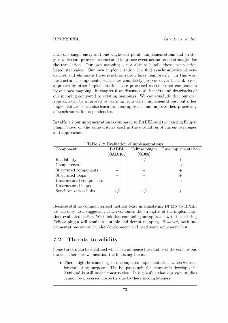
BPMN2BPEL Threats to validity
have one single entry and one single exit point. Implementations and strate-gies which can process unstructured loops use event-action based strategies forthe translation. Our own mapping is not able to handle these event-actionbased strategies. Our own implementation can find synchronization depen-dencies and eliminate these synchronization links temporarily. In this way,unstructured components, which are completely processed via the link-basedapproach by other implementations, are processed as structured componentsby our own mapping. In chapter 6 we discussed all benefits and drawbacks ofour mapping compared to existing mappings. We can conclude that our ownapproach can be improved by learning from other implementations, but otherimplementations can also learn from our approach and improve their processingof synchronization dependencies.
In table 7.2 our implementation is compared to BABEL and the existing Eclipseplugin based on the same criteria used in the evaluation of current strategiesand approaches.
Table 7.2: Evaluation of implementationsComponent BABEL Eclipse plugin Own implementation
[OADH08] [GB08]Readability + +/- +Completeness + + +/-Structured components + + +Structured loops + + +Unstructured components + + +/-Unstructured loops + + -Synchronization links +/- +/- +
Because still no common agreed method exist in translating BPMN to BPEL,we can only do a suggestion which combines the strengths of the implementa-tions evaluated earlier. We think that combining our approach with the existingEclipse plugin will result in a stable and decent mapping. However, both im-plementations are still under development and need some refinement first.
7.2 Threats to validity
Some threats can be identified which can influence the validity of the conclusionsdrawn. Therefore we mention the following threats:
• There might be some bugs or uncompleted implementations which we usedfor evaluating purposes. The Eclipse plugin for example is developed in2008 and is still under construction. It is possible that our case studiescannot be processed correctly due to these incompleteness.
73
BPMN2BPEL Conclusions
• Both case studies are from the financial sector. Other case studies fromother sectors might introduce new situations which cause problems thatare not covered yet by either the algorithm or the implementation. Forboth case studies, we tried to find a real business processes which coveras many workflow patterns [Web08b] as possible.
7.3 Future work
We see some needs and possibilities for future work, as discussed in chapter 6and extended here:
• Currently there are some problems in the implementation regarding mul-tiple decision and merge gateways. These issues must be resolved forfurther usage of the developed plugin.
• Some functionalities within the plugin need to be reimplemented. Due tothe medium level of JAVA knowledge available, some functions might havebeen implemented in a less efficient way. Performance of the translationin terms of speed and complexity was not in the scope of the project,since the plugin was not the main goal of the master project.
• The well-formed BPD restrictions which are described in chapter 6 andwhich can be relaxed, might be implemented in the plugin.
• The data perspective is not implemented yet. Research to the possibili-ties of translating the data perspective from BPMN to BPEL might beinteresting.
• Round-trip-engineering will need automated translations between BPMNto BPEL and vice versa. Research into translating BPEL to BPMN mighttherefore be an interesting subject. When both translations become moremature, we are convinced that the gap between process design and im-plementation will narrow down.
74

EINDHOVEN UNIVERSITY OF TECHNOLOGYDepartment of Industrial Engineering
BPMN 2 BPELAppendix
ByJeroen Blox
Supervisors:
R. Eshuis (TU/e)L. Muhlenberg (Logica)
J.C. van Gaalen (Logica)
Eindhoven, February 2009


BPMN2BPEL 2
Appendix A
BPMN explained
Events
An event is something that ”happens” during the business process and has arelation with the environment or other parties. Events affect the flow of theprocess and can have a cause(trigger) or an impact(result). There are differenttypes of events: Start, Intermediate and End.
Start event A start event indicates when a process will startand can not have any incoming arcs.
Intermediate event An intermediate event occurs somewhere betweenthe start and end event and does not start or ter-minate a process. Examples are message events ortimer events.
End event An end event will terminate the process and there-fore can not have any outgoing arcs.
Figure A.1: The basic elements used in BPMN[WAD+06b]
A-1
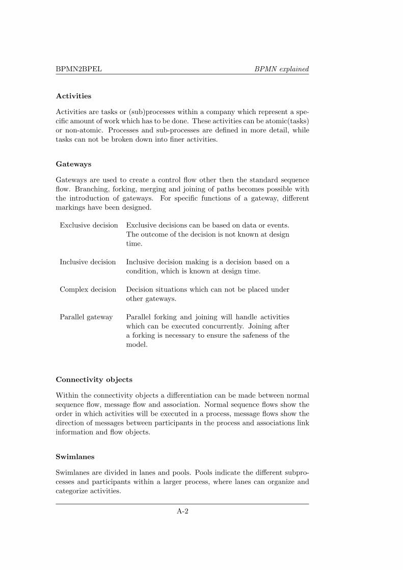
BPMN2BPEL BPMN explained
Activities
Activities are tasks or (sub)processes within a company which represent a spe-cific amount of work which has to be done. These activities can be atomic(tasks)or non-atomic. Processes and sub-processes are defined in more detail, whiletasks can not be broken down into finer activities.
Gateways
Gateways are used to create a control flow other then the standard sequenceflow. Branching, forking, merging and joining of paths becomes possible withthe introduction of gateways. For specific functions of a gateway, differentmarkings have been designed.
Exclusive decision Exclusive decisions can be based on data or events.The outcome of the decision is not known at designtime.
Inclusive decision Inclusive decision making is a decision based on acondition, which is known at design time.
Complex decision Decision situations which can not be placed underother gateways.
Parallel gateway Parallel forking and joining will handle activitieswhich can be executed concurrently. Joining aftera forking is necessary to ensure the safeness of themodel.
Connectivity objects
Within the connectivity objects a differentiation can be made between normalsequence flow, message flow and association. Normal sequence flows show theorder in which activities will be executed in a process, message flows show thedirection of messages between participants in the process and associations linkinformation and flow objects.
Swimlanes
Swimlanes are divided in lanes and pools. Pools indicate the different subpro-cesses and participants within a larger process, where lanes can organize andcategorize activities.
A-2

BPMN2BPEL
Artifacts
Three different artifacts can be identified in the BPMN specification. Dataobjects provide information about the requirements for executing activities andabout what they produce, but do not have any direct effect on the sequenceor message flow [OMG08b]. Groups are used for documentation and displaypurposes only, they also do not affect the flow. Text annotations are also onlymeant for additional information to the reader of the BPMN-models.
A-3

BPMN2BPEL BPMN explained
A-4
BPMN2BPEL 2
Appendix B
BPEL explained
The BPEL specification contains a lot of elements, which can be used for specificpurposes. A full list of BPEL elements can be found in [OAS07]. The mostcommon elements can be categorized into the following classes; basic activities,structured activities and partner links [OAS07].
Basic activities
Activities perform the process logic in BPEL. A distinction is made betweenbasic activities and structured activities. Basic activities describe elementalsteps of the process behavior, while structured activities describe the control-flow logic. Structured activities can contain other activities.
Invoke - The invoke activity is used to invoke Web Service operations. Theseoperations can be other web services, or can be activities which need to beexecuted by human people.
Receive and Reply - Business processes provide services to their part-ners through inbound message activities and corresponding reply activities. A(sub)process waits for a specific message, executes its activities and will send areply to the original initiator of the process. Multiple initiations can take placeat the same time.
Assign - The assign activity allows variables to be updated during the pro-cess.
Throw and Rethrow - For fault handling in BPEL, both the <throw> and<rethrow> activities can explicitly throw a fault to the faulthandler. Therethrow activity can throw the original fault message again to a fault handlerafter catching the fault.
A-5
BPMN2BPEL BPEL explained
Wait - When a business process needs a delay for a specific time, the waitactivity can be used. With the <for> or <until> element, a fixed duration ora fixed deadline can be specified.
Empty - The empty activity does nothing, but can be used to generate validand readable BPEL-code.
Exit - The exit activity immediately terminates all activities in the processinstance.
All activities can have two standard containers; <sources> and <targets>,with elements <source> and <target>. They are used to establish synchro-nization relationships through links.
Structured activities
Structured activities describe the control-flow logic of a business process. Theorder in which activities are executed is determined with these class of activities.
Sequence - Activities which are executed one by one in a given order, areplaced in a sequence control activity. The sequence activity completes whenthe last activity of the sequence is completed.
If - For conditional behavior, the <if> activity can be used. With the elements<elseif>, <else> and <condition> a conditional behavior can be described.Other (basic) activities will be placed in the different containers.
While and repeatUntil - The <while> activity provides a repeated set ofactivities and at the beginning of each cycle, the <condition> element mustbe evaluated successfully to true. Therefore it is possible that the <while>iteration is not visited. The <repeatUntil> activity evaluates the conditionafter executing it’s content and is always executed at least once.
Pick - The <pick> activity waits for an occurrence of one event and thenexecutes the activities related to this event. Other events where the <pick>activity was listening to are neglected. Only one event can be processed withthis activity.
Flow - The <flow> activity makes synchronization and concurrency possi-ble. Different groups of activities are initiated at the same moment. Withthe <link> elements, synchronization links can be identified and used with the<source> and <target> elements.
A-6

BPMN2BPEL
ForEach - ForEach makes it possible to process multiple branches. Depend-ing on the design of this activity, the children of this activity can be executedsequential or in parallel.
Partner Links
Partner links describe cross enterprise business interactions through Web Ser-vice interfaces. By describing the partner links, also roles are assigned to dif-ferent participants.
A-7

BPMN2BPEL BPEL explained
A-8

BPMN2BPEL 2
Appendix C
Existing BPMN 2 BPELapproaches
Table C.1: Existing approaches for translating BPMN to BPEL
Graph structure approach [Whi05]Strength The graph structure, which is used in BPMN models, is maintained.Weakness Generated BPEL might be hard to understand. Approach is not explained in
detail, but is only loosely described.Constr. Global process, namespace and variable information is needed, since a BPMN-
model normally does not contain this information.Compl. In his paper, White does not support al concepts. However it can be assumed
that a high level of completeness can be obtained as long the restrictions of the<link>-constructs are satisfied.
The BPMN to BPEL way [OADH08, ODHA08]Strength Arbitrary cycles are supported by using an event-based translation. The authors
discuss semantics and correctness in a concise and unambigious manner by in-troducing Petri nets. The approach can deal with all parallel gateways and xorgateways with arbitrary topology. Generated BPEL-code is readable, becauseblock-structured components are mapped before flow-based translation is used.
Weakness The approach uses events for unstructured (sub)processes, which results in lessreadable and comprehensible BPEL-code. Because of the combination of threeapproaches, implementation might be more difficult.
Constr. The BPMN model must satisfy the well-formed BPD-constraints. The BPMNmodel must be checked on deadlocks and multiple instances are not possible. Fortranslation using control links, these links may not result in cycles, may not haveevent-based gateways and must be safe and sound.
Compl. Any component can be translated, first well structured components are mapped,then the link-based and event-based approaches are used for resulting compo-nents.
Element-preservation strategy [MLZ06]Strength Easy to implement and both BPEL and the original process graph are graph-
based and easy to compare.Weakness Very difficult to understand because of the high number of elements and control
links.Constr. The process graph must be acyclic.Compl. Not all models can be translated using this approach, because of the restrictions
in the flow-based approach.Element-minimization strategy [MLZ06]
Strength In the spirit of the BPEL flow, which is graph-based. Also a good strategy whenperformance matters, since only really necessary elements are included.
Weakness By removing elements, it becomes less intuitive to identify correspondences.
A-9

BPMN2BPEL Existing BPMN 2 BPEL approaches
Constr. The process graph must be acyclic.Compl. Not all models can be translated using this approach, because of the restrictions
in the flow-based approach.Structure-identification strategy [MLZ06]
Strength Whole process graph translated to structured activities, which results in bestunderstanding of the generated BPEL-code.
Weakness The relation with the process graph might be less intuitive, since BPEL now isblock-structured.
Constr. The process graph must be structured, since every component must be mappedto structured activities.
Compl. Structured processes can be translated, unstructured processes not.Structure-maximization strategy [MLZ06]
Strength This approach also support unstructured processes, as long as loops can be re-duced by the structure-identification part.
Weakness Two different implementations are needed.Constr. Only cycles with a single entry and a single exit point are allowed in unstructured
processes.Compl. Almost any process can be translated, except for arbitrary cycles.
Event-condition action-rules strategy [MLZ06]Strength Any process graph can be translated, even unstructured loops.Weakness BPEL-code is difficult to understand and it is not clear how the approach behaves
with semantic problems.Constr. No specific constraints on input model.Compl. Any process can be translated.
The Petri nets approach [AL08]Strength Petri Nets have a strong theoretical foundation. Assuming the input Petri Net is
sound and safe, it can be guaranteed that a correct BPEL is generated.Weakness BPMN should first be mapped to Petri Nets.Constr. The input net should be safe and sound, it should have only one source, one sink
and every node is on a path from source to sink.Compl. The mapping between BPMN and Petri Nets is missing.
A-10
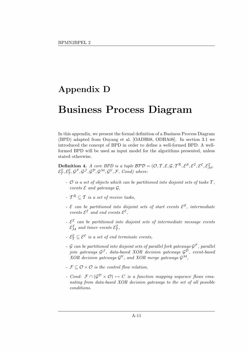
BPMN2BPEL 2
Appendix D
Business Process Diagram
In this appendix, we present the formal definition of a Business Process Diagram(BPD) adapted from Ouyang et al. [OADH08, ODHA08]. In section 3.1 weintroduced the concept of BPD in order to define a well-formed BPD. A well-formed BPD will be used as input model for the algorithms presented, unlessstated otherwise.
Definition 4. A core BPD is a tuple BPD = (O, T , E ,G, T R, ES , EI , EE , EIM,EIT , EET ,GF ,GJ ,GD,GM,GV ,F , Cond) where:
- O is a set of objects which can be partitioned into disjoint sets of tasks T ,events E and gateways G,
- T R ⊆ T is a set of receive tasks,
- E can be partitioned into disjoint sets of start events ES , intermediateevents EI and end events EE ,
- EI can be partitioned into disjoint sets of intermediate message eventsEIM and timer events EIT ,
- EET ⊆ EE is a set of end terminate events,
- G can be partitioned into disjoint sets of parallel fork gateways GF , paralleljoin gateways GJ , data-based XOR decision gateways GD, event-basedXOR decision gateways GV , and XOR merge gateways GM,
- F ⊆ O ×O is the control flow relation,
- Cond: F ∩ (GD × O) 7→ C is a function mapping sequence flows ema-nating from data-based XOR decision gateways to the set of all possibleconditions.
A-11

BPMN2BPEL Business Process Diagram
A-12
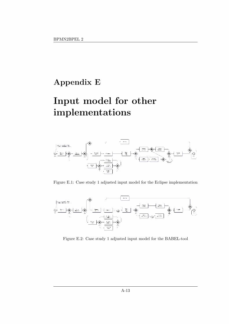
BPMN2BPEL 2
Appendix E
Input model for otherimplementations
Figure E.1: Case study 1 adjusted input model for the Eclipse implementation
Figure E.2: Case study 1 adjusted input model for the BABEL-tool
A-13
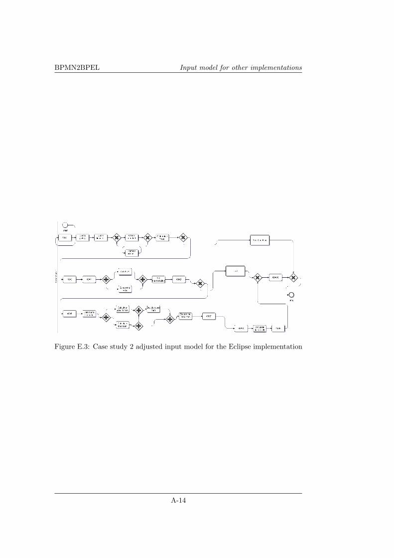
BPMN2BPEL Input model for other implementations
Figure E.3: Case study 2 adjusted input model for the Eclipse implementation
A-14
BPMN2BPEL 2 Bibliography
Bibliography
[AL08] W.M.P. van der Aalst and K.B. Lassen. Translating unstructuredworkflow process to readable BPEL: Theory and implementation.Information and Software Technology, Volume 50 , Issue 3:131–159, 2008.
[ASU86] A.V. Aho, R. Sethi, and J.D. Ullman. Compilers: Principles,Techniques, and Tools. Addison Wesley, 1986.
[BK05] F. van Breugel and M. Koshkina. Dead-path-elimination inBPEL4WS. Fifth International Conference on Application of Con-currency to System Design, 2005.
[Boe88] B.W. Boehm. A spiral model of software development and en-hancement. Computer, 21(5):61–72, May 1988.
[DDO08] R.M. Dijkman, M. Dumas, and C. Ouyang. Semantics and analysisof business process models in bpmn. Information and SoftwareTechnology, 50(12):1281–1294, 2008.
[Dum09] M. Dumas. Private conversation. 2009.
[EG09] R. Eshuis and P.W.P.J. Grefen. Composing services into struc-tured processes. International Journal of Cooperative InformationSystems, to be appear, 2009.
[Esh05] R. Eshuis. Statecharting petri nets. BETA Working Paper SeriesWP 153, 2005.
[GB08] L. Garcıa-Banuelos. Pattern identification and classification in thetranslation from bpmn to bpel. In OTM Conferences (1), pages436–444, 2008.
[MH08] M. zur Muehlen and D.T. Ho. Service process innovation: A casestudy of BPMN in practice. Hawaii International Conference onSystem Sciences, Proceedings of the 41st Annual:372–372, 2008.
A-15

BPMN2BPEL Bibliography
[MLZ06] J. Mendling, K.B. Lassen, and U. Zdun. On the transformationof control flow between block-oriented and graph-oriented processmodeling languages. Int. J. Business Process Integration and Man-agement, 2006.
[OADH06] C. Ouyang, W.M.P van der Aalst, M. Dumas, and A.H.M. terHofstede. From BPMN process models to BPEL web services.Proceedings of the 4th International Conference on Web Services,IEEE Computer Society:pages 285–292, 2006.
[OADH08] C. Ouyang, W.M.P. van der Aalst, M. Dumas, and A.H.M. terHofstede. From business process models to process-oriented soft-ware systems: The BPMN to BPEL way. ACM Transactions onSoftware Engineering and Methodology, 2008.
[OAS07] OASIS. Web Services Business Process Execution Language Ver-sion 2.0. OASIS Standard, 2007.
[ODHA08] C. Ouyang, M. Dumas, A.H.M. ter Hofstede, and W.M.P. vander Aalst. Pattern-based translation of BPMN process modelsto BPEL web services. International Journal of Web ServicesResearch, 5(1):42–62, 2008.
[OMG08a] OMG. Business Process Model and Notation (BPMN) Specifica-tion 2.0. 2008.
[OMG08b] OMG. Business Process Modeling Notation, V1.1. 2008.
[OYL08] C. Ou-Yang and Y. D. Lin. BPMN-based business process modelfeasibility analysis: a petri net approach. International Journal ofProduction Research, 46:3763 – 3781, 2008.
[RM06] J. Recker and J. Mendling. On the translation between BPMNand BPEL: Conceptual mismatch between process modeling lan-guages. Proceedings 18th International Conference on AdvancedInformation Systems Engineering, pages 521–532, 2006.
[VVK08] J. Vanhatalo, H. Volzer, and J. Koehler. The refined process struc-ture tree. BPM, pages 100–115, 2008.
[WAD+06a] P. Wohed, W.M.P. van der Aalst, M. Dumas, A.H.M. ter Hofstede,and N. Russell. On the suitability of BPMN for business processmodelling. Lecture notes in computer science, ISSN 0302-9743,2006.
[WAD+06b] P. Wohed, W.M.P. van der Aalst, M. Dumas, A.H.M. ter Hofstede,and N. Russell. Pattern-based analysis of BPMN - an extensiveevaluation of the control-flow, the data and the resource perspec-tives. BPM Center Report, BPM-06-17, 2006.
A-16
BPMN2BPEL Bibliography
[WADH03] P. Wohed, W.M.P. van der Aalst, M. Dumas, and A.H.M. ter Hof-stede. Analysis of web services composition languages: The case ofbpel4ws. In Song, I.Y., Liddle, S.W., Ling, T.W., Scheuermann,P., eds.: Conceptual Modeling - ER2003, 2813:200–215, 2003.
[WADH05] P. Wohed, W.M.P. van der Aalst, M. Dumas, and A.H.M. terHofstede. Pattern-based analysis of bpmn - an extensive evaluationof the control-flow, the data and the resource perspectives. BPMCenter Report, BPM-05-26, 2005.
[WADH06] P. Wohed, W.M.P. van der Aalst, M. Dumas, and A.H.M. terHofstede. Analysis of web services composition languages: Thecase of BPEL4WS. Proceedings 22nd International Conference onConceptual Modeling (ER), pages 200–215, 2006.
[Web08a] Website. Transforming BPMN into BPEL: Why andHow. http://www.oracle.com/technology/pub/articles/dikmans-bpm.html?rrsid=rss, 12 September 2008.
[Web08b] Website. Workflow patterns. http://www.workflowpatterns.com/,25 September 2008.
[Web08c] Website. BPEL Implementations. http://www.oasis-open.org/-news/oasis-news-2007-04-12.php, 29 September 2008.
[Web08d] Website. BPMN Implementations. http://www.bpmn.org-/BPMN Supporters.htm, 29 September 2008.
[Whi05] S.A. White. Using BPMN to model a BPEL process. IBM whitepaper, 2005.
A-17