Embed Size (px)
Citation preview

Metal Building Systems
Installation and Flashings & Details Guide
Section Page
Notes to Designer/User . . . . . . . . . . . . . . . . . .1-2
Map of Typical Roof Conditions . . . . . . . . . . . .3
Fastener Placement . . . . . . . . . . . . . . . . . . . . . . .4
Fastener Selection . . . . . . . . . . . . . . . . . . . . . . . .5
Box-Rib, Reverse Box Rib, HR-36,
Mini-V-Beam and Super Span Details
Ridge/Hip Flashing . . . . . . . . . . . . . . . . . . . . . .6
Valley Flashing . . . . . . . . . . . . . . . . . . . . . . . . .7
Eave Flashings . . . . . . . . . . . . . . . . . . . . . . . . .8
Gutter Flashings . . . . . . . . . . . . . . . . . . . . . . . .9
Gable Flashings . . . . . . . . . . . . . . . . . . . . . . . .10
Peak Flashing . . . . . . . . . . . . . . . . . . . . . . . . .11
Sidewall Flashings . . . . . . . . . . . . . . . . . . . . .12
Endwall Flashing . . . . . . . . . . . . . . . . . . . . . . .13
Panel End Lap . . . . . . . . . . . . . . . . . . . . . . . . .14
Window/Door Trim . . . . . . . . . . . . . . . . . . . . .15
Drip Edge/Wall Step, Panel Top . . . . . . . . . . .16
Inside Corner . . . . . . . . . . . . . . . . . . . . . . . . . .17
Outside Corner . . . . . . . . . . . . . . . . . . . . . . . .18
Nu-Wave Corrugated Details
Ridge/Hip Flashing . . . . . . . . . . . . . . . . . . . . .19
Valley Flashing . . . . . . . . . . . . . . . . . . . . . . . .20
Eave Flashing . . . . . . . . . . . . . . . . . . . . . . . . .21
Gutter Flashing . . . . . . . . . . . . . . . . . . . . . . . .22
Gable Flashing . . . . . . . . . . . . . . . . . . . . . . . .23
Peak Flashing . . . . . . . . . . . . . . . . . . . . . . . . .24
Sidewall Flashing . . . . . . . . . . . . . . . . . . . . . .25
Endwall Flashing . . . . . . . . . . . . . . . . . . . . . .26
Base Trim Detail . . . . . . . . . . . . . . . . . . . . . . .27
“C” Trim Detail . . . . . . . . . . . . . . . . . . . . . . .28
Inside Corner . . . . . . . . . . . . . . . . . . . . . . . . .29
Outside Corner . . . . . . . . . . . . . . . . . . . . . . . .30
Table of Contents

Metal Systems Installation • September 2000 1
Metal Building Systems
Installation and Flashings & Details Guide
The details contained in this packet are intended to be adesign aid and do not depict all situations.Modifications are the responsibility of the designer/userand should take into account climate conditions such aswind and snow, governing code requirements, and theactual usage and maintenance of the structure. Wherepossible, roof panel side laps and flashings should belapped away from prevailing winds. Certain flashingsshould be supported if it is likely that a ladder will beused against them or if foot traffic is anticipated. Checkwith IMSA Building Products any time you intend tospecify a prefinished flashing in a gauge different thanthe panels. Our standard gauge for most of the productsin this booklet is 24-gauge and the standard finish isKynar 500®/Hylar 5000® (PVF2 polyvinylidene fluo-ride). It is good practice to specify that all flashings beof the same material as the panels (gauge, color, finish)to ensure long-term durability. Field-painted flashingsrarely equal the durability and color fastness of factorybaked-on paint systems. Where possible, we havehemmed the edges of flashings to strengthen them andto minimize the exposure of cut edges.
Framing- The details contained in this guide are shownwith panels attached to spaced support members.
Slope requirements- It is suggested that all panels inthis booklet be used on slopes of 1:12 or greater, exceptNu-Wave Corrugated® which has a 3:12 minimumslope.
Condensation, Insulation & Ventilation- It is thedesigner’s responsibility to determine the need andcomposition of condensation control materials includ-ing insulation and vapor retarders, as well as ventilationrequirements. Metal roofing is susceptible to condensa-tion and its control should be carefully considered.
Valleys- Valley dimensions must be the proper width to
account for slope, snow, ice, and rain conditions. If val-leys are not kept free of debris, water does back up andintrusion may occur under the panels.
Snow Design- If possible, valleys, gutters, roof eleva-tion changes and penetrations should be minimized oreliminated in snow areas. Roof penetrations should belocated as close to the ridge or peak of the roof as possi-ble to minimize accumulations of ice and snow.
Curved Roofs- Box Rib, HR-36, Super Span and Nu-Wave Corrugated® panels are suitable for installa-tion over curved surfaces. Box Rib, HR-36 and SuperSpan panels are factory crimp curved. Nu-WaveCorrugated panels are factory smooth curved. Mini-V-Beam panels are not available curved.
Oil-Canning- Flat metal surfaces will display wavinesscommonly referred to as “oil-canning”. This is causedby steel mill tolerances, variations in the substrate androofing underlayments. Oil canning is a characteristic,not a defect, of panels manufactured from light-gaugemetal. Coils are factory “corrective-levelled” prior tomanufacturing to minimize oil canning. Oil canning isnot a cause for panel rejection. Additional information isavailable upon request.
References- The Sheet Metal and Air ConditioningContractors’ National Association Inc. (SMACNA)manual is an excellent reference for sheet metal contrac-tors. Its guidelines for underlayments, gutter and down-spout size requirements, and expansion/contraction ofmetals and flashings joints should be followed.
Technical Assistance- Call your IMSA BuildingProducts Sales or Technical Representative for addition-al information on any of these subjects.
Notes to the Designer/User

2 Metal Systems Installation • October 2000
Metal Building Systems
Installation and Flashings & Details Guide
Definitions-
• Sealant: Gunnable-grade single-componentpolyurethane or butyl rubber• Mastic: Butyl mastic tape• Hem: A 180˚ bend that is closed (or as closed as the
formability of the metalwill allow) to provide auniform, attractive edge.
High tensile strength (Grade 80) steel must be formedwith a “teardrop hem” as shown to avoid cracking thesteel at the bend. Lower tensile steels can be flattenedclose.
• Hook: (also called an“open hem”) A 180˚bend on a piece of sheet
metal that is left open to allow insertion of another pieceof sheet metal. For example, the hook shown is used tohold the trim piece to a cleat below the trim.
Each flashing part in this guide has been assigned apart number. Each part number contains one or two let-ters followed by one or two numbers, for example:(EW6). These part numbers have been provided for youto make ordering these flashing parts quick and easy.
Notes to the Designer/Usercontinued

Metal Systems Installation • October 2000 3
For suggestions on how to trim flashings in the different areas, please refer to the following pages:
Flashing Page(s)
Eave . . . . . . . . . . . . . . . . . . . . . . . . . . . . .8, 21Endwall . . . . . . . . . . . . . . . . . . . . . . . . .13, 26Gable . . . . . . . . . . . . . . . . . . . . . . . . . . .10, 23Gutter . . . . . . . . . . . . . . . . . . . . . . . . . . . .9, 22Panel Endlap . . . . . . . . . . . . . . . . . . . . . . . . .14
Flashing Page(s)
Peak . . . . . . . . . . . . . . . . . . . . . . . . . . . .11, 24Ridge/Hip . . . . . . . . . . . . . . . . . . . . . . . . .6, 19Sidewall . . . . . . . . . . . . . . . . . . . . . . . . .12, 25Valley . . . . . . . . . . . . . . . . . . . . . . . . . . . .7, 20
Map of Typical Roof Conditions
IMSA Building Products
4 Metal Systems Installation • October 2000
Metal Building Systems
Installation and Flashings & Details Guide
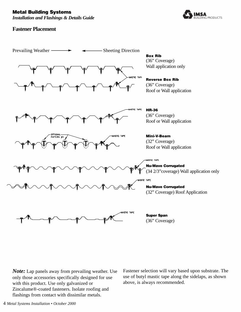
Fastener Placement
Box Rib
(36” Coverage)Wall application only
Reverse Box Rib
(36” Coverage)Roof or Wall application
HR-36
(36” Coverage)Roof or Wall application
Mini-V-Beam
(32” Coverage)Roof or Wall application
Nu-Wave Corrugated
(34 2/3”coverage) Wall application only
Super Span
(36” Coverage)
Note: Lap panels away from prevailing weather. Useonly those accessories specifically designed for usewith this product. Use only galvanized orZincalume®-coated fasteners. Isolate roofing andflashings from contact with dissimilar metals.
Fastener selection will vary based upon substrate. Theuse of butyl mastic tape along the sidelaps, as shownabove, is always recommended.
Prevailing Weather Sheeting Direction
Nu-Wave Corrugated
(32” Coverage) Roof Application

Fastener Selection
Fastener # Description Use
#9 x 1”, 1 1/2”, 2”, 2 1/2”, 3”Wood Screw1/4” Hex Head
#14 x 1”, 2” Wood Screw5/16” Hex Head
#12 x 3/4” Stitch Screw1/4” Hex Head (compatiblewith #10 wood screw)
#14 x 7/8” Lap Self Driller5/16” Hex Head (compatiblewith #14 wood screw)
STST–42 Stainless Steel Rivet1/8 x 1/8
#12 x 1”, 1 1/2”, 2”, 1 1/2”Self Driller5/16” Hex Head
Panel toDimensional Lumber
Panel to PlywoodMinimum 1/2” thick,structural grade
Trim and side lapattachments
Trim and side lap attachments.Attach panels to 18, 20, 22gauge supports.
Trim-to-trim or trim-to-panel attachments
Panel to purlinattachments
Notes: • The table above shows the metal buildings panel fasteners provided by
IMSA. Refer to the panel flashing details and fastener placement pages of this manual for specific usage.
• Panel attachment screws must be long enough to fully penetrate through the roof decking, or penetrate solid lumber at least one inch.
• All screws must be coated to provide protection against corrosion.• Exposed fasteners should have sealing washers and be the same color as
the parts they attach.• Roofing nails will also be required, but not furnished by IMSA. They are
typically used to temporarily hold a flashing in place that needs to be installed prior to panels.
• Screws must be properly driven to ensure proper seal and holding strength.Do not underdrive or overdrive the screws. Recommended drill speed is 2000 rpm. Use of a depth-sensing nosepiece will aid in properly driving screws.
Proper Installation of Gasketed Fasteners
CorrectlyDriven
UnderDriven
OverDriven
Metal Systems Installation • October 2000 5
IMSA Building Products

IMSA BP
6 Metal Systems Installation • October 2000
Metal Building Systems
Installation and Flashings & Details Guide
Ridge/Hip Flashing
Formed Ridge (R6)Super Span
Formed Ridge (R11)HR-36 and Box Rib
IMSA BP
Metal Systems Installation • October 2000 7
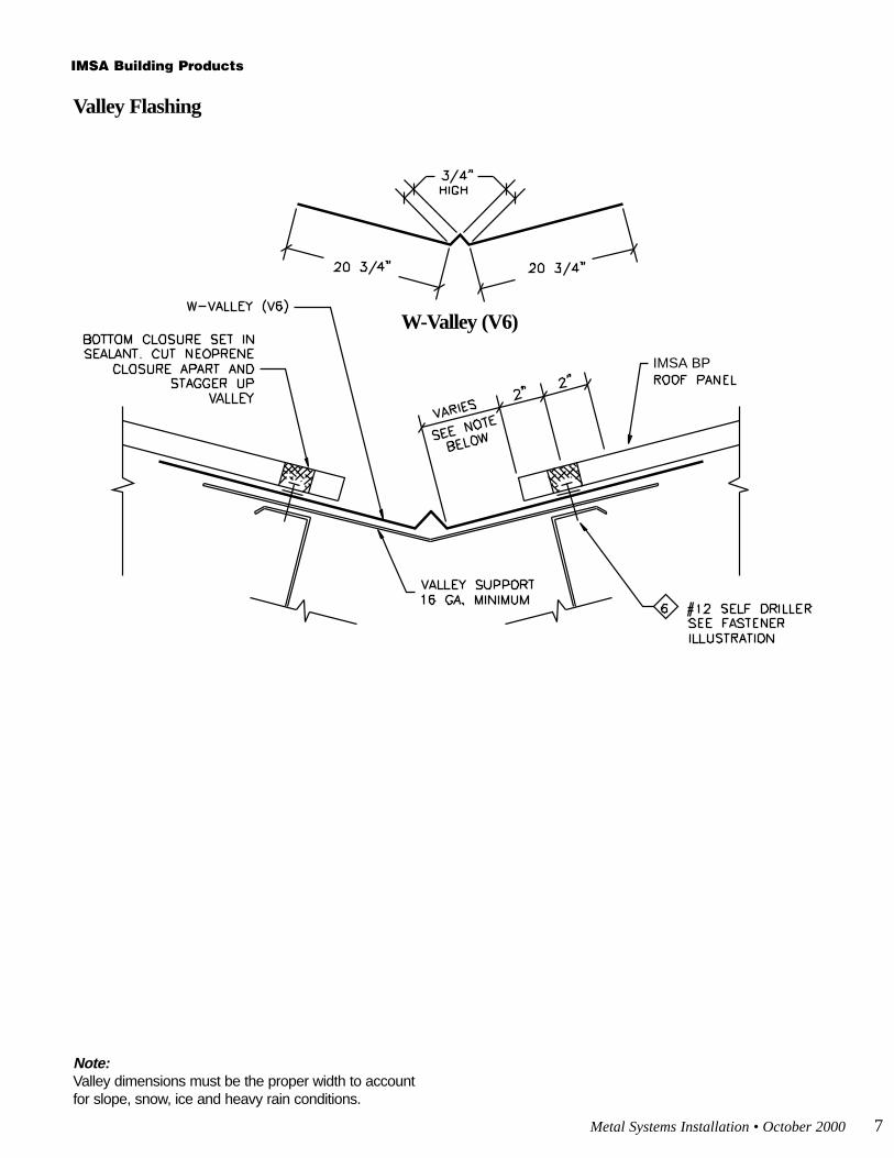
Valley Flashing
W-Valley (V6)
Note:Valley dimensions must be the proper width to accountfor slope, snow, ice and heavy rain conditions.
IMSA Building Products

8 Metal Systems Installation • October 2000
Metal Building Systems
Installation and Flashings & Details Guide
Eave Flashing
IMSA BP
Eave (E6) Sculptured Eave (E7)optional

Metal Systems Installation • October 2000 9
Gutter Flashings
IMSA BP
Box Gutter (GU6)pre-hung
Sculptured Gutter (GU7)pre-hung
Sculptured Gutter (GU9)post-hung
Box Gutter (GU8)pre-hung
IMSA Building Products

10 Metal Systems Installation • October 2000
Metal Building Systems
Installation and Flashings & Details Guide
Gable Flashings
IMSA BP
Gable Trim (G8)Super Span only Sculptured Gable Trim (G15)
Sculptured Gable Trim (G9)HR-36 only
Gable Trim (G12)

IMSA BP
Metal Systems Installation • October 2000 11
Peak Flashings
Peak (PF16)
IMSA Building Products

12 Metal Systems Installation • October 2000
Metal Building Systems
Installation and Flashings & Details Guide
Sidewall Flashings
IMSA BP
IMSA BP
Sidewall (SW7) Sidewall (SW8)optional

IMSA BP
IMSA BP
Metal Systems Installation • October 2000 13
Endwall Flashing
Endwall (EW6)
IMSA Building Products

14 Metal Systems Installation • October 2000
Metal Building Systems
Installation and Flashings & Details Guide
Panel Endlap
IMSA BP

Metal Systems Installation • October 2000 15
Wall DetailsWindow/Door Trim
IMSA BP
C-Metal (C-6)Super Span only
Jamb Trim (J6)Super Span only
C-Metal (C12)Mini -V-Beam
C-Metal (C-13)Nu-Wave
C-Metal (C11)Box Rib & HR-336
IMSA Building Products

IMSA BP
16 Metal Systems Installation • October 2000
Metal Building Systems
Installation and Flashings & Details Guide
Wall DetailsDrip Edge, Wall Step, Panel Top
Drip Edge (B6)

Metal Systems Installation • October 2000 17
Wall DetailsInside Corner
IMSA BP
Inside Corner (IC7) Inside Corner (IC 11)
IMSA Building Products

18 Metal Systems Installation • October 2000
Metal Building Systems
Installation and Flashings & Details Guide
Wall DetailsOutside Corner
IMSA BP
Outside Corner (OC7)Super Span only
Outside Corner (OC11)

IMSA BP NU-WAVE
Metal Systems Installation • October 2000 19
NuWave Corrugated Ridge/Hip Flashing
Ridge/Hip (R8)
IMSA Building Products
Note: Fasteners (exceptunder
ridge cap) should be located on
tops of corrugations.
20 Metal Systems Installation • October 2000
Metal Building Systems
Installation and Flashings & Details Guide
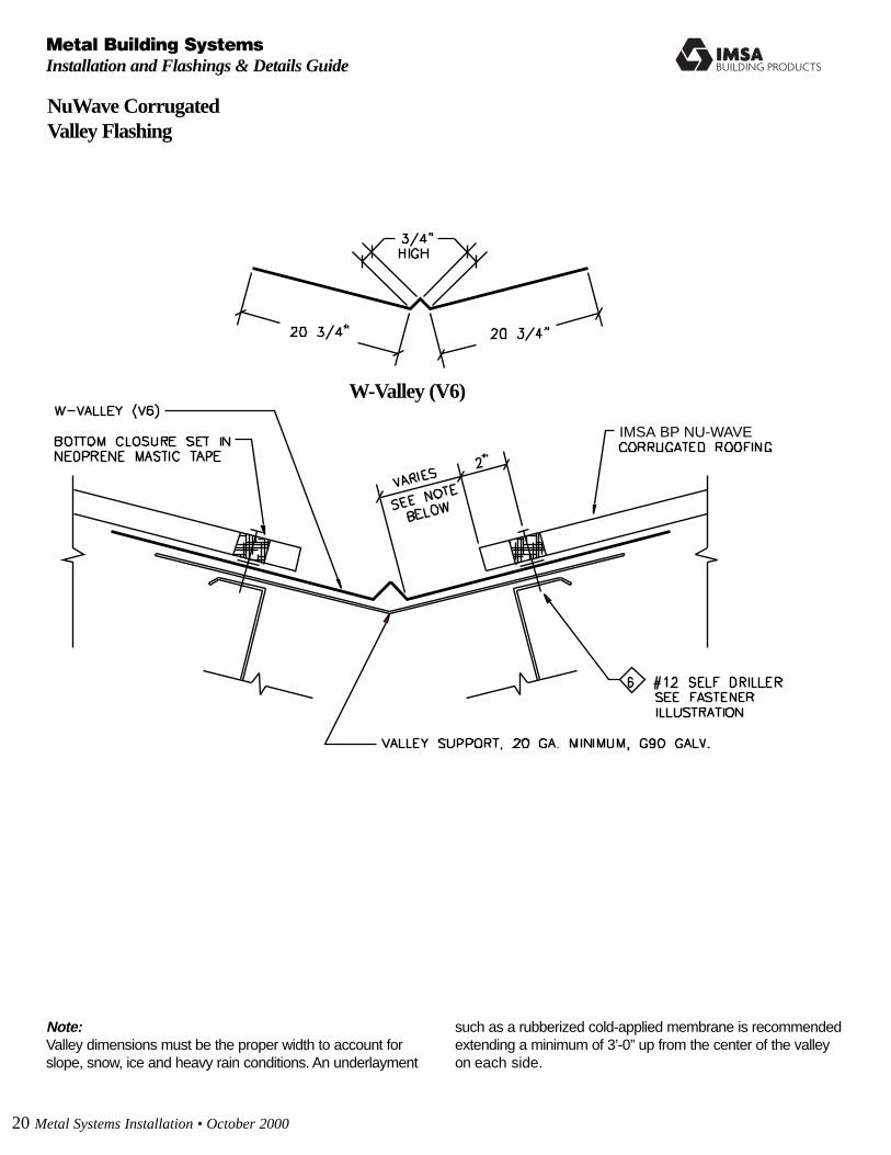
NuWave CorrugatedValley Flashing
Note:Valley dimensions must be the proper width to account forslope, snow, ice and heavy rain conditions. An underlayment
such as a rubberized cold-applied membrane is recommendedextending a minimum of 3’-0” up from the center of the valleyon each side.
IMSA BP NU-WAVE
W-Valley (V6)

IMSA NU-WAVE
Metal Systems Installation • October 2000 21
NuWave CorrugatedEave Flashing
Eave (E6)
IMSA Building Products

IMSA BP NU-WAVE
22 Metal Systems Installation • October 2000
Metal Building Systems
Installation and Flashings & Details Guide
NuWave CorrugatedGutter Flashing
Box Gutter (GU6)pre-hung

IMSA BP NU-WAVE
NuWave CorrugatedGable Flashing
Gable Trim (G12)
Metal Systems Installation • October 2000 23
IMSA Building Products

IMSA BP NU-WAVE
24 Metal Systems Installation • October 2000
Metal Building Systems
Installation and Flashings & Details Guide
NuWave CorrugatedPeak Flashing
Peak (PF16)

IMSA BP NU-WAVE
IMSA BP NU-WAVE
Metal Systems Installation • October 2000 25
NuWave CorrugatedSidewall Flashing
Sidewall (SW8)
IMSA Building Products
26 Metal Systems Installation • October 2000
Metal Building Systems
Installation and Flashings & Details Guide
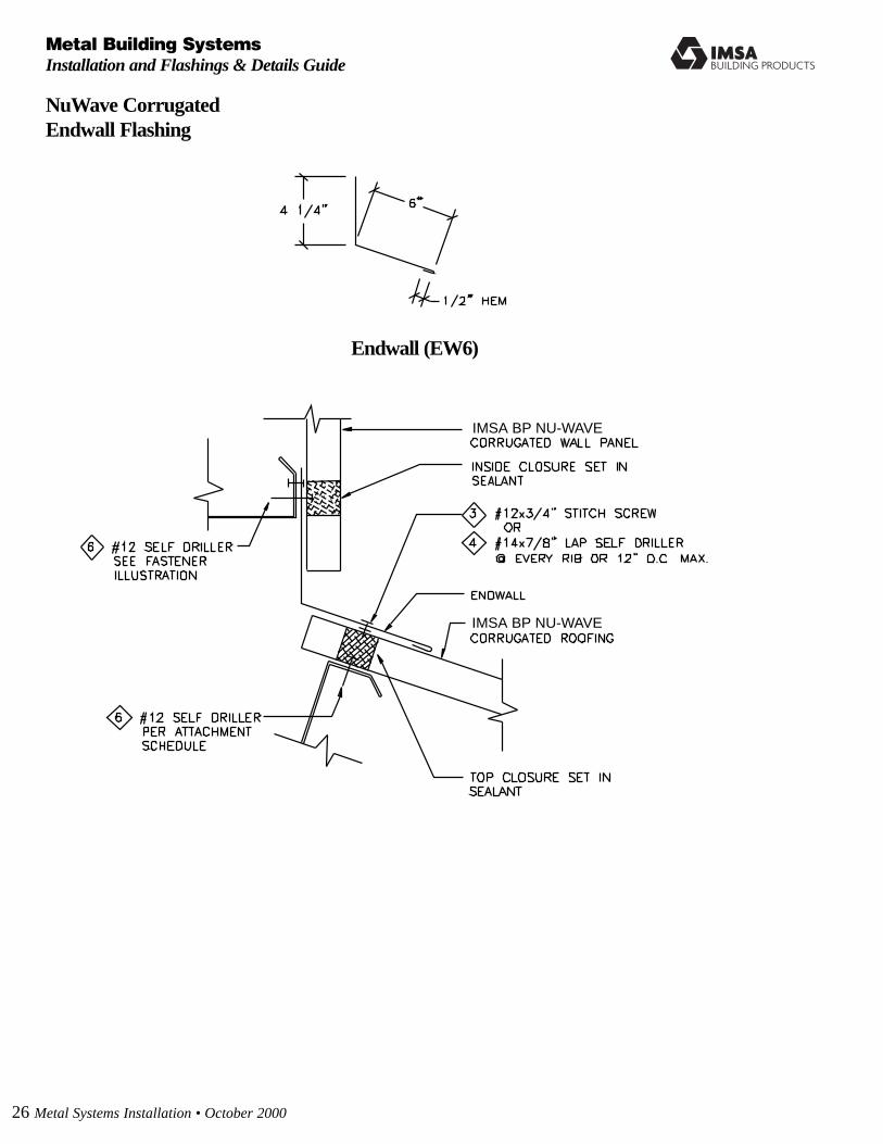
NuWave CorrugatedEndwall Flashing
IMSA BP NU-WAVE
IMSA BP NU-WAVE
Endwall (EW6)

IMSA BP NU-WAVE
Metal Systems Installation • October 2000 27
NuWave CorrugatedWall Details - Base Trim
Base Trim (B1)
IMSA Building Products

IMSA BP NU-WAVE
28 Metal Systems Installation • October 2000
Metal Building Systems
Installation and Flashings & Details Guide
NuWave CorrugatedWall Details - “C” Trim
“C” Trim (C13)

, TYP.
, TYP.
, TYP.
IMSA BP NU-WAVE
Metal Systems Installation • October 2000 29
NuWave CorrugatedWall Details - Inside Corner
Inside Corner (IC2)
IMSA Building Products
IMSA BP NU-WAVE
, TYP.
, TYP.
, TYP.
30 Metal Systems Installation • October 2000
Metal Building Systems
Installation and Flashings & Details Guide
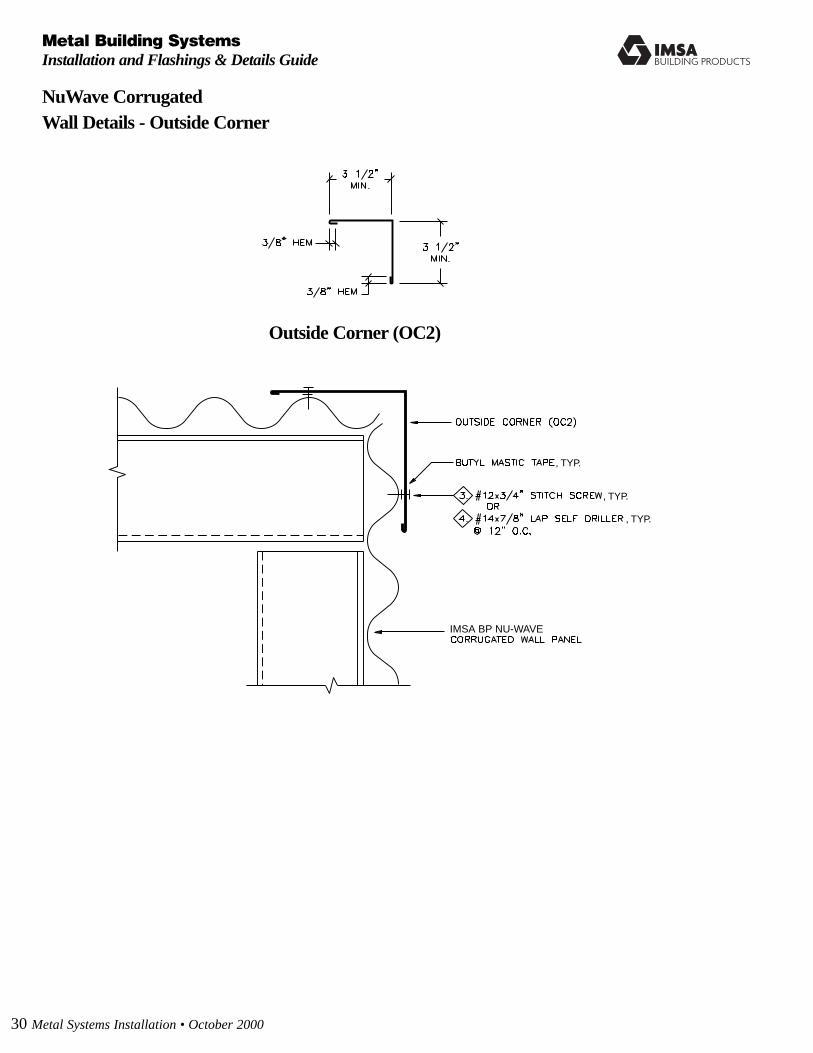
NuWave CorrugatedWall Details - Outside Corner
Outside Corner (OC2)

Zincalume® is a registered trademark of BHP Steel (JLA) Pty. Ltd.©IMSA Building Products Inc. October 2000 Printed in the USA 5M (BR137)
Manufacturing Facilities:
IMSA Building Products • Tacoma
2141 Milwaukee Way
Tacoma, WA 98421
253-383-4955
800-733-4955
IMSA Building Products • Fontana
10905 Beech Avenue
Fontana, CA 92337
Tacoma, WA 98421
909-823-0401
800-272-2466
Corporate Headquarters:
IMSA Building Products Inc.
2110 Enterprise Boulevard
West Sacramento, CA 95691
916-360-2477
800-360-2477
www.imsaproducts.com
IMSABUILDING PRODUCTS