Embed Size (px)
Citation preview
®
®
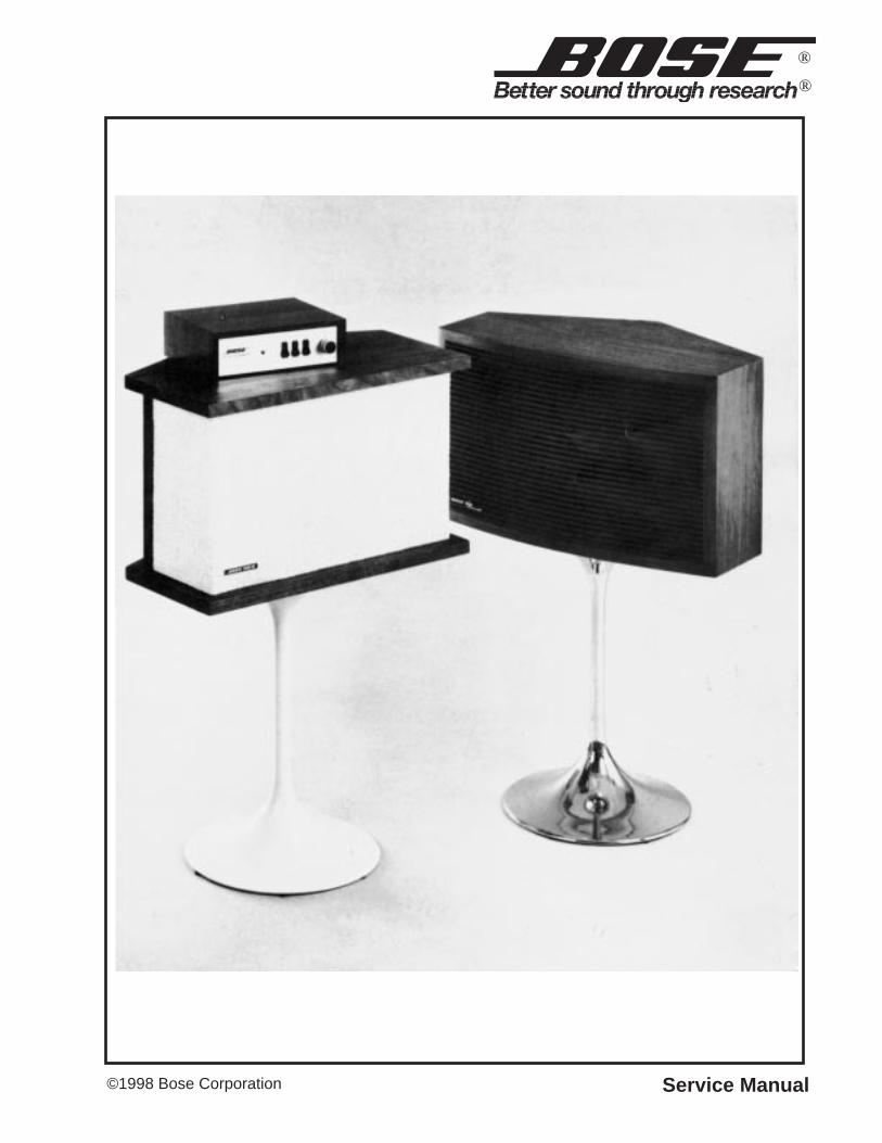
©1998 Bose Corporation Service Manual

2
PROPRIETARY INFORMATION
THIS DOCUMENT CONTAINS PROPRIETARY INFORMATION OFBOSE® CORPORATION WHICH IS BEING FURNISHED ONLY FORTHE PURPOSE OF SERVICING THE IDENTIFIED BOSE PRODUCTBY AN AUTHORIZED BOSE SERVICE CENTER OR OWNER OF THE
BOSE PRODUCT, AND SHALL NOT BE REPRODUCED OR USED FOR ANY OTHER PURPOSE.
Contents
Safety Information ............................................................................................................. ............... 3Specifications ................................................................................................................. .................. 4Technical Description .......................................................................................................... ......... 5-6Figure 1. Equalizer Controls Response Charts ................................................................................ 6
Disassemble/Assembly Procedure ............................................................................................. 7-8Figure 2. Staple Location ................................................................................................................. 7Figure 3. Staple Removal Tool ......................................................................................................... 7Figure 4. Wiring Diagram ................................................................................................................. 7Figure 5. Top Cover .......................................................................................................................... 9Figure 6. Front Panel Assembly ....................................................................................................... 9Figure 7. Indicator Lens Assembly ................................................................................................... 9
Test Procedure ................................................................................................................. ......... 10-11Figure 8. Test Set-Up ..................................................................................................................... 10
Part List ...................................................................................................................... ..................... 12Part List Notes ................................................................................................................ ................ 12Figure 9. 901 I Schematic Diagram................................................................................................ 13Figure 10. 901 II Schematic Diagram............................................................................................. 14Figure 11. 901 Schematic Diagram (first production run) ............................................................... 15
3
CAUTION: THE BOSE ® 901 I and II EQUALIZERS CONTAIN NO USER-SERVICEABLEPARTS. TO PREVENT WARRANTY INFRACTIONS, REFER SERVICE TO WARRANTYSERVICE STATIONS OR FACTORY SERVICE.
SAFETY INFORMATION
1. Parts that have special safety characteristics are identified by the symbol on schematics or by special notes on the parts list. Use only replacement parts that
have critical characteristics recommended by the manufacturer.
2. Make leakage current or resistance measurements to determine that exposed parts are acceptably insulated from the supply circuit before returning the unit
to the customer. Use the following checks to perform these measurements:
A. Leakage Current Hot Check -With the unit completely reassembled, plugthe AC line cord directly into a 120V AC outlet. (Do not use an isolationtransformer during this test.) Use a leakage current tester or a meteringsystem that complies with American National Standards Institute (ANSI)C101.1 “Leakage Current for Appliances” and Underwriters Laboratories(UL) 1492 (71). With the unit AC switch first in the ON position, then in theOFF position, measure from a known earth ground (metal water pipe,conduit, etc.) to all exposed metal parts of the unit (antennas, handle bracket,metal cabinet, screw heads, metallic overlays, control shafts, etc.), especiallyany exposed metal parts that offer an electrical return path to the chassis.Any current measured must not exceed 0.5 milliamp. Reverse the unit powercord plug in the outlet and repeat test. ANY MEASUREMENTS NOT WITHINTHE LIMITS SPECIFIED HEREIN INDICATE A POTENTIAL SHOCK HAZ-
ARD THAT MUST BE ELIMINATED BEFORE RETURNING THE UNIT TO THE CUSTOMER.
B. Insulation Resistance Test Cold Check -(1) Unplug the power supply andconnect a jumper wire between the two prongs of the plug. (2) Turn on the
power switch of the unit. (3) Measure the resistance with an ohmmeter be- tween the jumpered AC plug and each exposed metallic cabinet part on the unit. When the exposed metallic part has a return path to the chassis, the reading should be between 1 and 5.2 Megohms. When there is no return path
to the chassis, the reading must be “infinite”. If it is not within the limits specified, there is the possibility of a shock hazard, and the unit must be repaired and re- checked before it is returned to the customer.
4
SPECIFICATIONS
901 Series I and II Speaker
Dimensions: 20-9/16" W x 12-3/4" H x 12-7/8" D
Weight: 33 lbs
Nominal Impedance: 8 ohms
Percentages of Direct and Reflected Sound Radiation
Power radiated byreflection: 89%
Power radiated directly: 11%
Power Handling: Continuous sine wave @ any frequency: 50 WattsMinimum amplifier power: 25 WattsPeak power (less than 5 seconds): 400 WattsMaximum amplifier power: 270 Watts rms
@8 ohms
Damping Factor: Any amplifier with a damping factor of 40 or higher(must follow the speaker wire recommendation in the Owner's Guide)
Driver Complement: Nominal driver diameter: 4-1/2"Maximum driver excursion: ± 1/4"Nominal driver impedance: 8 ohmsWeight of each ceramic magnet: 9.6 ounces
901 Active Equalizer
Dimensions: 2-13/16" H x 9-1/4" W x 6-3/4" D
Input Impedance: 150k ohms
Output Impedance: Less than 100 ohms
Minimum LoadImpedance: 5k ohms
Maximum OutputVoltage: 4.0 Volts
Maximum Gain: 18 dB @ 35 Hz

5
TECHNICAL DESCRIPTION
The Bose® 901 speakers represent a fundamental advance in realistic home music reproduc-tion. The unique acoustic design of the speakers provide sound distribution in accurate simula-tion of live sound. The Active Equalizer provides unprecedented accuracy and control offrequency response characteristics.
Each speaker contains nine high compliance, full range speakers with high energy magnets toallow large excursions without audible distortion on any program material. The speakers areacoustically coupled to eliminate audible resonances.
The 901 speakers can be used with any high quality amplifier. Its efficiency enables operationwith moderately powered amplifiers, yet it can be used with the highest powered amplifiers toreproduce undistorted orchestral peaks at high volume levels.
The Bose 901 Active Equalizer is a highly sophisticated electronic console containing tentransistors and more than a hundred components to equalize accurately the stereo responsefor the effects of radiation impedances, speaker characteristics, enclosure dimensions andeven for the presence of the fashion fabric grille cloth. This equalization to flat power radiationis achieved with absolutely no audible distortion of any music or speech signals.
Active equalization of the signal before the power amplifier is far superior to passive equaliza-tion after the amplifier because it avoids the need to handle high power and does not requirethe iron-core inductors that introduce distortion in passive equalizers. In addition, it is feasibleto use many more elements in an active network to provide much greater accuracy in equaliza-tion than is practical in the passive network.
The Active Equalizer does much more than just equalize. In addition to providing the flatacoustic output of the Bose 901, the Active Equalizer offers the choice of nineteen additionalcontours that can be selected from the front panel. This gives the listener the flexibility toexercise his own taste in compensating for recording techniques, listening room characteristicsand the other variables described above. As an example of what is possible through activeequalization, the equalizer panel contains a switch marked "BELOW 40", which reducesturntable rumble and other low frequency disturbances through a unique filter design thatprovides a uniform attenuation below 40 Hz while causing no audible deviations above 50 Hz.The rumble is removed without removing the life of the bass along with it.

6
TECHNICAL DESCRIPTION
Figure 1. Equalizer Controls Response Charts

DISASSEMBLE/ASSEMBLY PROCEDURE901 Speaker Disassembly/Assembly
1. Grille Removal
1.1 Locate the staples that secure the frontor rear grille assembly. Refer to Figures 2and 3 for the staple placement and tool forremoving the staples.
1.2 When removing the front grille assem-bly, note the placement of the cut out in thegrille backing.
2. Grille Replacement
2.1 Place the front grille assembly over thefront of the speaker. Note the cut out in thegrille backing, be sure to align the cut outwith the driver ( on late versions the frontgrille assembly had two cut outs so thegrille placement would not be a factor whenreassembling the speaker). Secure usingnew staples or small finishing nails.
2.2 Place the rear grille assembly on to thespeaker and secure using new staples orsmall finishing nails.
3. Driver Removal
3.1 Perform procedure 1.
3.2 Remove the screws that secure thedefective driver.
3.3 Lift the driver out of the cabinet and cutthe speaker wire as close to the driverterminals as possible.
4. Driver Replacement
4.1 Connect the speaker wires to the newdriver. Refer to Figure 4 for the wire dia-gram.
4.2 Place the new driver and gasket intothe cabinet and secure it in place.
4.3 Perform procedure 2.
Figure 2. Staple Location
Figure 3. Staple Removal Tool Figure 4. Wiring Diagram
Flat Blade Screwdriver
Machined to a Hook
7
8
DISASSEMBLE/ASSEMBLY PROCEDURE901 EQ Disassembly/Assembly
5. PCB Removal
5.1 Perform procedure 1.
5.2 Remove the four screws that securethe PCB to the chassis and lift the PCB out.
6. PCB Replacement
6.1 Place the PCB into the chassis andsecure it to the chassis.
6.2 Perform procedure 2.
7. Treble Control Removal
7.1 Perform procedure 3.
7.2 Remove the wires form the control,make note of the placement of the wires.
8. Treble Control Replacement
8.1 Solder the wires onto the control.
8.2 Place the control into the chassis andsecure it in place.
8.3 Perform procedure 4.
9. Switch Removal
9.1 Perform procedure 3.
9.2 Remove the wires from the switch,make note of the placement of the wires.
9.3 Remove the rivets that secure theswitch to the chassis, using a drill.
10. Switch Replacement
10.1 Secure the new switch to the chassisusing rivets or screws.
10.2 Solder the wires to the switch.
10.3 Perform procedure 4.
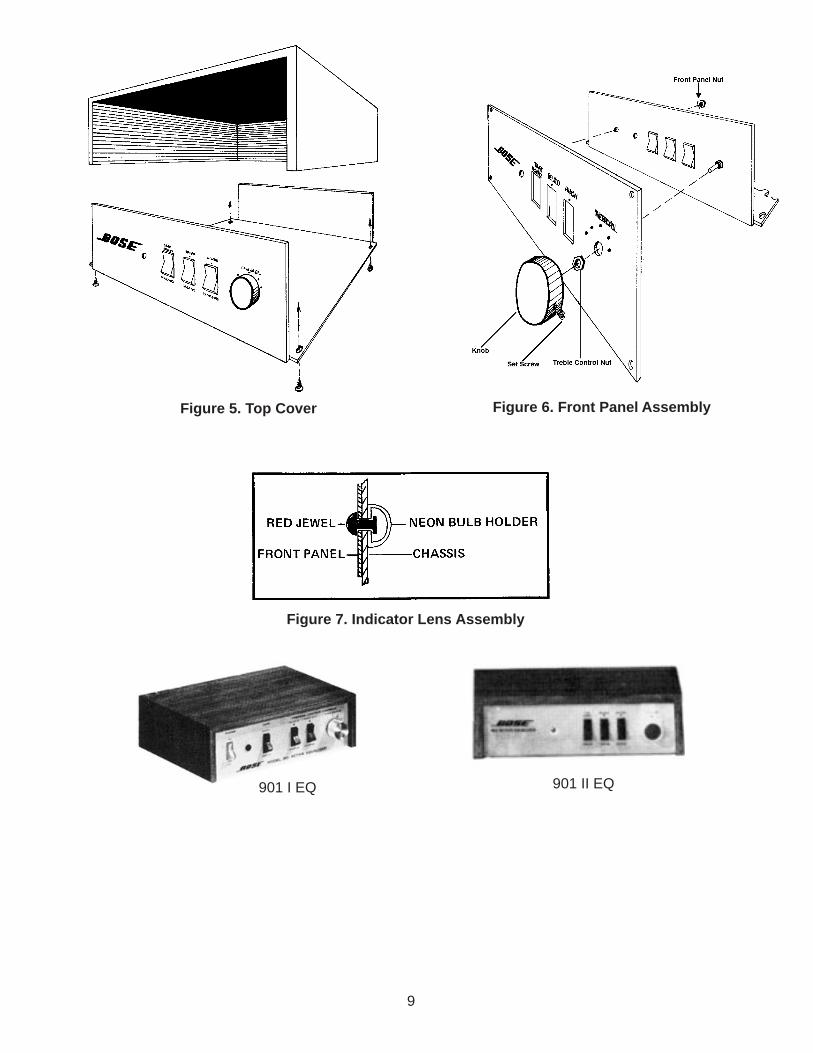
Note: Refer to figures 5 and 6 for thefollowing procedures.
1. Top Cover Removal
1.1 Turn the unit over (top down) andremove the four screws located at each ofthe corners.
1.2 Flip the unit back over and remove thetop cover.
2. Top Cover Replacement
2.1 Align the top cover with the front panel(there is a groove in the top cover for thefront panel to slide into).
2.2 Flip the unit over and secure the topcover using the screws that had beenremoved.
3. Front Panel RemovalNote: The series II EQ has a red indicatorlens. Refer to Figure 7. for removal.
3.1 Perform procedure 1.
3.2 Remove the treble control knob usingan Allen Wrench to loosen the set screw.
3.3 Remove the nut holding the treblecontrol to the chassis.
3.4 Remove the small nut on the inside ofthe chassis that secures the front panel tothe chassis.
4. Front Panel Replacement
4.1 Align the front panel screw with thechassis.
4.2 Secure the front panel to the chassis.
4.3 Secure the treble control to the chassisand replace the control knob.
4.4 Perform procedure 2.
9
901 I EQ 901 II EQ
Figure 5. Top Cover Figure 6. Front Panel Assembly
Figure 7. Indicator Lens Assembly
10
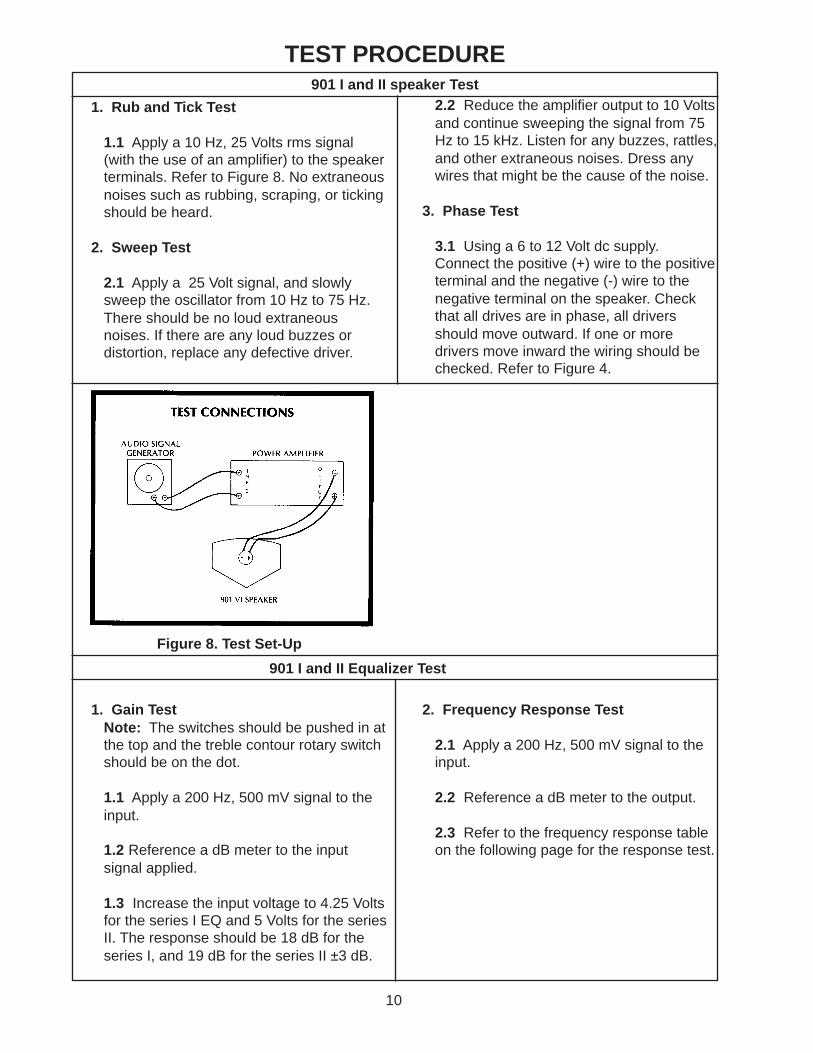
TEST PROCEDURE
1. Rub and Tick Test
1.1 Apply a 10 Hz, 25 Volts rms signal(with the use of an amplifier) to the speakerterminals. Refer to Figure 8. No extraneousnoises such as rubbing, scraping, or tickingshould be heard.
2. Sweep Test
2.1 Apply a 25 Volt signal, and slowlysweep the oscillator from 10 Hz to 75 Hz.There should be no loud extraneousnoises. If there are any loud buzzes ordistortion, replace any defective driver.
2.2 Reduce the amplifier output to 10 Voltsand continue sweeping the signal from 75Hz to 15 kHz. Listen for any buzzes, rattles,and other extraneous noises. Dress anywires that might be the cause of the noise.
3. Phase Test
3.1 Using a 6 to 12 Volt dc supply.Connect the positive (+) wire to the positiveterminal and the negative (-) wire to thenegative terminal on the speaker. Checkthat all drives are in phase, all driversshould move outward. If one or moredrivers move inward the wiring should bechecked. Refer to Figure 4.
Figure 8. Test Set-Up
901 I and II speaker Test
901 I and II Equalizer Test
1. Gain TestNote: The switches should be pushed in atthe top and the treble contour rotary switchshould be on the dot.
1.1 Apply a 200 Hz, 500 mV signal to theinput.
1.2 Reference a dB meter to the inputsignal applied.
1.3 Increase the input voltage to 4.25 Voltsfor the series I EQ and 5 Volts for the seriesII. The response should be 18 dB for theseries I, and 19 dB for the series II ±3 dB.
2. Frequency Response Test
2.1 Apply a 200 Hz, 500 mV signal to theinput.
2.2 Reference a dB meter to the output.
2.3 Refer to the frequency response tableon the following page for the response test.

11
TEST PROCEDURE
Frequency Response Table
Frequency Below 40Switch
TrebleDecrease
Switch
TrebleContour
ResponsedB
901 I
ResponsedB
901 II
TolerancedB
20 Hz OFF OFF normal (dot) 14.8 dB 19 dB ±3 dB20 Hz ON OFF normal (dot) 9 dB 9.5 dB ±3 dB60 Hz OFF OFF normal (dot) 9.2 dB 9.4 dB ±3 dB60 Hz ON OFF normal (dot) 8 dB 7.8 dB ±3 dB1 kHz OFF OFF normal (dot) .2 dB .1 dB ±3 dB5 kHz OFF OFF normal (dot) 2.2 dB 4 dB ±3 dB12 kHz OFF OFF normal (dot) 9 dB 12.3 dB ±3 dB12 kHz OFF ON normal (dot) 6.9 dB 8.1 dB ±3 dB12 kHz OFF OFF number 1 2.7 dB 7 dB ±3 dB12 kHz OFF OFF number 2 3.2 dB 7.8 dB ±3 dB12 kHz OFF OFF number 3 7.3 dB --- ±3 dB12 kHz OFF OFF number 4 --- 15.6 dB ±3 dB12 kHz OFF OFF number 5 12.4 dB 18.5 dB ±3 dB20 kHz OFF OFF normal (dot) 12.9 dB 13.8 dB ±3 dB

12
PART LIST
901 Speaker Part ListItem
NumberDescription Part
NumberNote
--- Driver 103342 4--- Grille, Front 103514-03 4--- Grille, Rear 103512-03 4--- Grille, Front , Ebony 103514-02 4--- Knurled Nut 100424-1--- Fuse Kit (External) 108938-3
901 EQ Part ListReferenceDesignator
Description PartNumber
Note
T1 Transformer 110V, 220V 100099 3
S5 Power Switch 100399 3
S1, 3, 4 Rocker Switch 100400S2 Rotary Switch 100420--- Lens Housing, 110V 116327 3
--- Indicator Lens 103460--- Front Panel 100416-1 Series II--- Line Cord, 110V 111672 3
--- Line Cord, 220V 113608 3
--- Knob, Treble Contuor 103457R1 10k ohm Resistor 102537 for 220V
Q1-5, Q51-57 Transistor 102437-2D1, 2 Diode 100259-1
1. This part is not normally available from Customer Service. Approval from the Field ServiceManager is required before ordering.
2. The individual parts located on the PCB are listed in the Electrical Part List.
3. This part is critical for safety purposes. Failure to use a substitute replacement withthe same safety characteristics as the recommended replacement part might create shock,fire, and or other hazards.
4. These parts are no longer available.
PART LIST NOTES
13
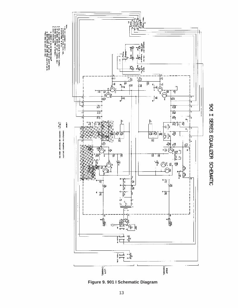
Figure 9. 901 I Schematic Diagram

14
Figure 10. 901 II Schematic Diagram
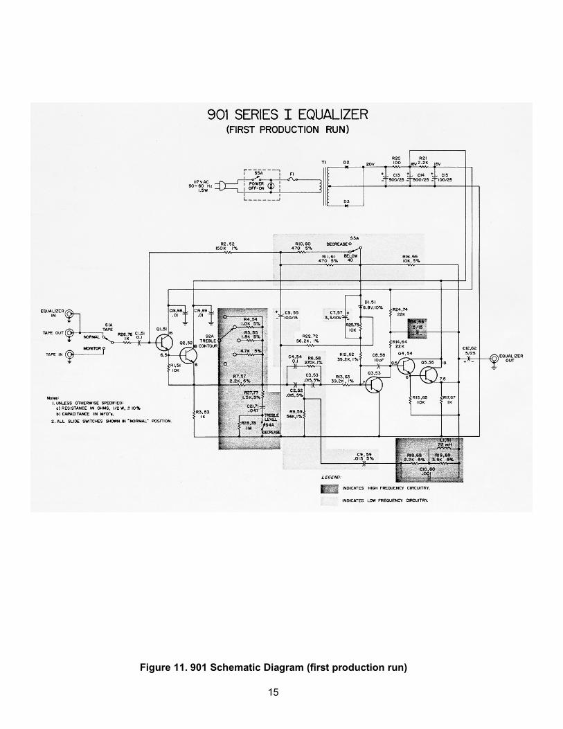
Figure 11. 901 Schematic Diagram (first production run)
15