Embed Size (px)
Citation preview

Bosch BOVA Split System Heat PumpCondensing Units Up to 18 SEER 2-3-4-5 Ton CapacityR410A
Installation Instructions

2 | Bosch IDS BOVA Installation Instructions
12.2016 | Bosch Thermotechnology Corp.Data subject to change

Installation Instructions Bosch IDS BOVA | 3
Bosch Thermotechnology Corp. | 12.2016 Data subject to change
Table of Contents
1 Key to symbols and safety instructions 4
2 Unit location considerations 6
3 Unit preparation 8
4 Setting the unit 8
5 Refrigerant line considerations 9
6 Refrigerant line routing 10
7 Refrigerant line brazing 11
8 Refrigerant line leak check 13
9 Evacuation 13
10 Service valves 14
11 Electrical - low voltage 15
12 Electrical - high voltage 16
13 Start up 17
14 System charge adjustment 18
15 System operation and troubleshooting 21
4 | Bosch IDS BOVA Installation Instructions
12.2016 | Bosch Thermotechnology Corp.Data subject to change
1 Key to symbols and safety instructions
1.1 Key to symbols Warnings
Warnings in this document are identifi ed by a warning triangle printed against a grey background.Keywords at the start of a warning indicate the type and seriousness of the ensuing risk if measures to prevent the risk are not taken.
The following keywords are defi ned and can be used in this document:
DANGER indicates a hazardous situation which, if not avoided, will result in death or serious injury.
WARNING indicates a hazardous situation which, if not avoided, could result in death or serious injury.
CAUTION indicates a hazardous situation which, if not avoided, could result in minor to moderate injury.
NOTICE is used to address practices not related to personal injury.
Important information
This symbol indicates important information wherethere is no risk to people or property.
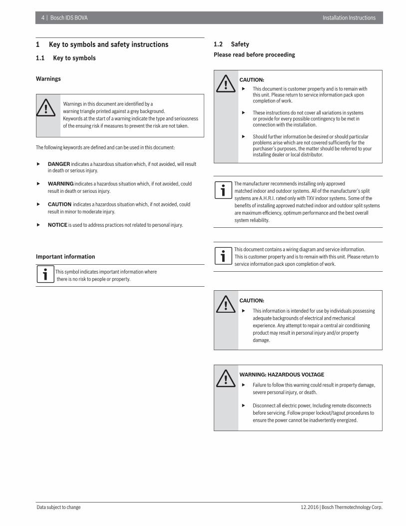
1.2 SafetyPlease read before proceeding
CAUTION:
This document is customer property and is to remain with this unit. Please return to service information pack upon completion of work.
These instructions do not cover all variations in systems or provide for every possible contingency to be met in connection with the installation.
Should further information be desired or should particular problems arise which are not covered sufficiently for the purchaser’s purposes, the matter should be referred to your installing dealer or local distributor.
The manufacturer recommends installing only approved matched indoor and outdoor systems. All of the manufacturer’s split systems are A.H.R.I. rated only with TXV indoor systems. Some of the benefi ts of installing approved matched indoor and outdoor split systems are maximum effi ciency, optimum performance and the best overall system reliability.
This document contains a wiring diagram and service information. This is customer property and is to remain with this unit. Please return to service information pack upon completion of work.
CAUTION:
This information is intended for use by individuals possessing adequate backgrounds of electrical and mechanical experience. Any attempt to repair a central air conditioning product may result in personal injury and/or property damage.
WARNING: HAZARDOUS VOLTAGE
Failure to follow this warning could result in property damage, severe personal injury, or death.
Disconnect all electric power, Including remote disconnects before servicing. Follow proper lockout/tagout procedures to ensure the power cannot be inadvertently energized.

Installation Instructions Bosch IDS BOVA | 5
Bosch Thermotechnology Corp. | 12.2016 Data subject to change
WARNING: REFRIGERANT OIL
Any attempt to repair a central air conditioning product may result in property damage, severe personal injury, or death. These units use R-410A refrigerant which operates at 50 to 70% higher pressures than R-22. Use only R-410A approved service equipment. Refrigerant cylin-ders are painted a “Rose” color to indicate the type of refrigerant and may contain a “dip” tube to allow for charging of liquid refrigerant into the system. All R-410A systems with variable speed compressors use a PVE oil that readily absorbs moisture from the atmosphere To limit this ‘hygroscopic“ action. the system should remain sealed whenever possible. If a system has been open to the atmosphere for more than 4 hours, the compressor oil must be replaced. Never break a vacuum with air and always change the driers when opening the system for component replacement.
CAUTION: HOT SURFACE
May cause minor to severe burning. Failure to follow this Caution could result in property damage or personal injury. Do not touch top of compressor.
CAUTION: CONTAINS REFRIGERANT
Failure to follow proper procedures can result in personal illness or injury or severe equipment damage.System contains oil and refrigerant under high pressure. Recover refrigerant to relieve pressure before opening system.
CAUTION: GROUNDING REQUIRED
Failure to inspect or use proper service tools may result in equipment damage or personal injury. Reconnect all grounding devices. All parts of this product that are capable of conducting electrical current are grounded. if grounding wires, screws, straps, clips, nuts, or washers used to complete a path to ground are removed for service, they must be returned to their original position and properly fastened.
CAUTION: INDOOR UNIT REQUIRED
The indoor units must be matched with TXV. The model of TXV can be changed according to the system capacity.
WARNING: SERVICE VALVES
Failure to follow this warning will result in abrupt release of system charge and may result in personal injury and/or property damage. Extreme caution should be exercised when opening the Liquid Line Service valve. Turn valve stem counterclockwise only until the stem contacts the rolled edge. No torque is required.
WARNING: BRAZING REQUIRED
Failure to inspect lines or use proper service tools may result in equipment damage or personal injury. if using existing refrigerant lines make certain that all joints are brazed, not soldered.
WARNING: HIGH CURRENT LEAKAGE
Failure to follow this warning could result in property damage, severe personal injury, or death. Grounding is essential before connecting electrical supply.

6 | Bosch IDS BOVA Installation Instructions
12.2016 | Bosch Thermotechnology Corp.Data subject to change
2 Unit location considerations
2.1 Unit dimensions
Unit Dimensions
Models H x W x L (Inches)
BOVA-36 24-15/16 x 29-1/8 x 29-1/8
BOVA-60 33-3/16 x 29-1/8 x 29-1/8
Table 1
The unit’s weight values is on the carton box.
When mounting the outdoor unit on a roof, be sure the roof will support the unit’s weight. Properly selected isolation is recommended to prevent sound or vibration transmission to the building structure.
L
H
W
Figure 1
2.2 Refrigerant piping limits
Maximum line equivalent length = 100 feet.
Maximum vertical equivalent length = 50 feet.
Use only the line diameters indicated in Table 5.1.
If the suction line sets are greater than 60 feet do not use a larger suction line than recommended.
Standard LineSet 100’ MaxLine Length
50’ MaxLine Lift
50’ MaxLine Lift
Figure 2

Installation Instructions Bosch IDS BOVA | 7
Bosch Thermotechnology Corp. | 12.2016 Data subject to change
2.3 Location restrictionsEnsure the top discharge area is unrestricted for at least 60 inches above the unit.
Do not locate outdoor unit near bedrooms since normal operational sounds may be objectionable.
Position unit to allow adequate space for unobstructed airfl ow, wiring, refrigerant lines, and serviceability.
Allow a minimum of 12 in. clearance on one side of access panel to a wall and a minimum of 24 in. on the adjacent side of access panel.
Maintain a distance of 24 in. between units.
Position unit so water, snow, or ice from roof or overhang cannot fall directly on unit.
See Fig. 3 and Fig. 4.
Cold climate considerations (heat pump only)
Precautions must be taken for units being installed in areas wheresnow accumulation and prolonged below-freezing temperatures occur.
Units should be elevated 3-12 inches above the pad or rooftop, depending on local weather. This addi-tional height will allow drainage of snow and ice melted durIng defrost cycle prior to its refreezlng. Ensure that drain holes in unit base pan are not obstructed, preventing drainage of defrost water (Fig. 5).
If possible, avoid locations that are likely to accu-mulate snow drifts. if not possible, a snow drift barrier should be installed around the unit to prevent a build-up of snow on the sides of the unit.
Min. 20” toShrubbery
Avoid Install Near Bedrooms
Min. 60” Unrestricted
Access Panel
Min. 36”Unrestricted
Figure 3
Min. 20” toShrubbery
Min. 36” toShrubber
Access Panel
Figure 4
Min 12"
Snow barrier
3- 12" Elevation
Snow legs
pad
Figure 5
8 | Bosch IDS BOVA Installation Instructions
12.2016 | Bosch Thermotechnology Corp.Data subject to change
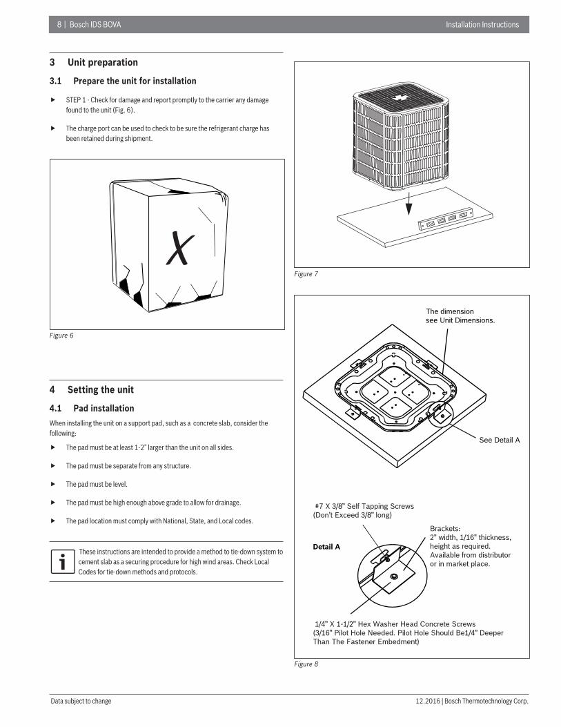
3 Unit preparation
3.1 Prepare the unit for installation
STEP 1 - Check for damage and report promptly to the carrier any damage found to the unit (Fig. 6).
The charge port can be used to check to be sure the refrigerant charge has been retained during shipment.
Figure 6
4 Setting the unit
4.1 Pad installationWhen installing the unit on a support pad, such as a concrete slab, consider the following:
The pad must be at least 1-2” larger than the unit on all sides.
The pad must be separate from any structure.
The pad must be level.
The pad must be high enough above grade to allow for drainage.
The pad location must comply with National, State, and Local codes.
These instructions are intended to provide a method to tie-down system to cement slab as a securing procedure for high wind areas. Check Local Codes for tie-down methods and protocols.
Figure 7
#7 X 3/8” Self Tapping Screws (Don’t Exceed 3/8” long)
Detail A
The dimension see Unit Dimensions.
See Detail A
Brackets:2" width, 1/16" thickness,height as required.Available from distributoror in market place.
1/4” Χ 1-1/2” Hex Washer Head Concrete Screws (3/16” Pilot Hole Needed. Pilot Hole Should Be1/4” Deeper Than The Fastener Embedment)
Figure 8
Installation Instructions Bosch IDS BOVA | 9
Bosch Thermotechnology Corp. | 12.2016 Data subject to change
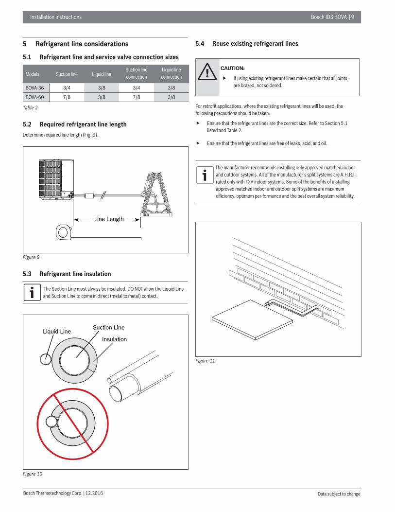
5 Refrigerant line considerations
5.1 Refrigerant line and service valve connection sizes
Models Suction line Liquid lineSuction line connection
Liquid line connection
BOVA-36 3/4 3/8 3/4 3/8
BOVA-60 7/8 3/8 7/8 3/8
Table 2
5.2 Required refrigerant line lengthDetermine required line length (Fig. 9).
Line Length
Figure 9
5.3 Refrigerant line insulation
The Suction Line must always be insulated. DO NOT allow the Liquid Line and Suction Line to come in direct (metal to metal) contact.
Suction LineLiquid LineInsulation
Figure 10
5.4 Reuse existing refrigerant lines
CAUTION:
If using existing refrigerant lines make certain that all joints are brazed, not soldered.
For retrofi t applications, where the existing refrigerant lines will be used, the following precautions should be taken:
Ensure that the refrigerant lines are the correct size. Refer to Section 5.1 listed and Table 2.
Ensure that the refrigerant lines are free of leaks, acid, and oil.
The manufacturer recommends installing only approved matched indoor and outdoor systems. All of the manufacturer’s split systems are A.H.R.I. rated only with TXV indoor systems. Some of the benefi ts of installing approved matched indoor and outdoor split systems are maximum effi ciency, optimum per-formance and the best overall system reliability.
Figure 11

1 0 | Bosch IDS BOVA Installation Instructions
12.2016 | Bosch Thermotechnology Corp.Data subject to change
6 Refrigerant line routing
6.1 Precautions
Take precautions to prevent noise within the building structure due to vibration transmission from the refrigerant lines. For Example:
When the refrigerant lines have to be fastened to floor joists or other framing in a structure, use isolation type hangers.
Isolation hangers should also be used when refrigerant lines are run in stud spaces or enclosed ceilings.
Where the refrigerant lines run through a wall or sill, they should be insulated and isolated.
Isolate the lines from all ductwork.
Minimize the number of 90º turns.
Isolation From Joist/Rafter
Side View
8 Feet MaximumJoist/Rafter
Isolator
Line Set8 Feet Maximum
Secure Suction line from joists us ing isolators every 8 ft . SecureLiquid Line directly to Suction line using tape, wire, or otherappropriate method every 8 ft.
Figure 12
Isolation In Wall Spaces
Side View
Wall
Isolator
Line Set
8 Feet Maximum
Secure Suction Line using isolators every 8 ft . Secure Liqu id Linedirectly to Suction Line using tape, wire, or other appropriatemethod every 8 ft.
8 Feet Maximum
Figure 13
Comply with National, State, and Local Codes when isolating line sets from joists, rafters, walls, or other structural elements.

Installation Instructions Bosch IDS BOVA | 11
Bosch Thermotechnology Corp. | 12.2016 Data subject to change
Isolation Through Wall DO NOT hang line sets from duc twork
Sealant
Insulation
Suction Line
Wall
Ductwork
Isolator
Line Set
Figure 14
7 Refrigerant line brazing
7.1 Braze the refrigerant lines1. Remove caps or plugs. Use a deburing tool to debur the pipe ends. Clean both
internal and external surfaces of the tubing using an emery cloth.
Figure 15
1 2 | Bosch IDS BOVA Installation Instructions
12.2016 | Bosch Thermotechnology Corp.Data subject to change
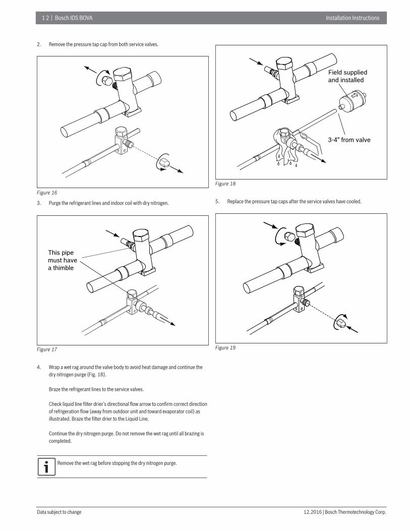
2. Remove the pressure tap cap from both service valves.
Figure 16
3. Purge the refrigerant lines and indoor coil with dry nitrogen.
This pipemust havea thimble
Figure 17
4. Wrap a wet rag around the valve body to avoid heat damage and continue the dry nitrogen purge (Fig. 18).
Braze the refrigerant lines to the service valves.
Check liquid line fi lter drier’s directional fl ow arrow to confi rm correct direction of refrigeration fl ow (away from outdoor unit and toward evaporator coil) as illustrated. Braze the fi lter drier to the Liquid Line.
Continue the dry nitrogen purge. Do not remove the wet rag until all brazing is completed.
Remove the wet rag before stopping the dry nitrogen purge.
Field supplied and installed
3-4" from valve
Figure 18
5. Replace the pressure tap caps after the service valves have cooled.
Figure 19

Installation Instructions Bosch IDS BOVA | 13
Bosch Thermotechnology Corp. | 12.2016 Data subject to change
8 Refrigerant line leak check
8.1 Check for leaks 1. Pressurize the refrigerant lines and evaporator coil to 150 PSIG using dry
nitrogen.
150 PSI G
Figure 20
2. Check for leaks by using a soapy solution or bubbles at each brazed location.
Figure 21
9 Evacuation
9.1 Evacuate the refrigerant lines and indoor coil
Do not open the service valves until the refrigerant lines and indoor coil leak check and evacuation are complete.
1. Evacuate until the micron gauge reads no higher than 350 microns, then close the valve to the vacuum pump.
0350Microns
ON OFF
Figure 22
2. Observe the micron gauge. Evacuation is complete if the micron gauge does not rise above 500 microns in one (1) minute.
Once evacuation is complete blank off the vacuum pump and micron gauge, and close the valves on the manifold gauge set.
1 MIN.
Figure 23

1 4 | Bosch IDS BOVA Installation Instructions
12.2016 | Bosch Thermotechnology Corp.Data subject to change
10 Service valves
10.1 Open the service valves
WARNING:
Extreme caution should be exercised when opening the Liquid Line Service Valve. Turn counterclock wise until the valve stem just touches the rolled edge. No torque is required. Failure to follow this warning will result in abrupt release of system charge and may result in personal injury and /or property damage.
Leak check and evacuation must be com pleted before opening the service valves.
The Suction Service Valve must be opened fi rst BEFORE opening the Liquid Service Valve!
1. Remove service valve cap (Fig 24).
2. Fully insert hex wrench into the stem and back out counterclockwise until valve stem just touches the rolled edge (approximately five (5) turns.)
3. Replace the valve stem cap to prevent leaks. Tighten finger tight plus an additional 1/6 turn.
4. Repeat STEPS 1 - 3 for Liquid Service Valve.
Cap
Rolled Edge toCaptivate Stem
Hex HeadedValve System
Service Port
3/16” Hex Wrenchfor Liqu id Service Valve
5/16” Hex Wrenchfor Suction Service Valve
Unit S ideof Service
Valve
Figure 24
Installation Instructions Bosch IDS BOVA | 15
Bosch Thermotechnology Corp. | 12.2016 Data subject to change
11 Electrical - low voltage
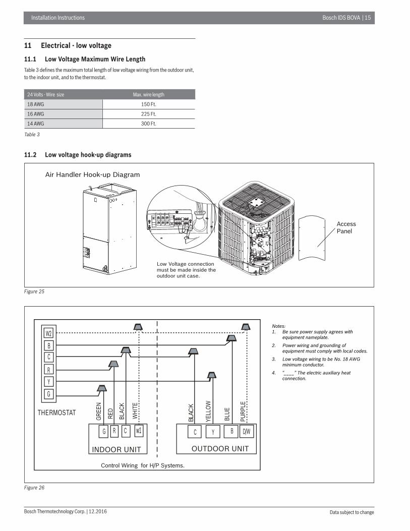
11.1 Low Voltage Maximum Wire LengthTable 3 defi nes the maximum total length of low voltage wiring from the outdoor unit, to the indoor unit, and to the thermostat.
24 Volts - Wire size Max. wire length
18 AWG 150 Ft.
16 AWG 225 Ft.
14 AWG 300 Ft.
Table 3
11.2 Low voltage hook-up diagrams
Air Handler Hook-up Diagram
Low Voltage connectionmust be made inside theoutdoor unit case.
AccessPanel
Figure 25
THERMOSTAT
C
INDOOR UNIT OUTDOOR UNIT
Y
RG Y
BLAC
K
G
C
C B
R
B
Control Wiring for H/P Systems.
W2
D/Ww1
Notes:1. Be sure power supply agrees with equipment nameplate.2. Power wiring and grounding of equipment must comply with local codes. 3. Low voltage wiring to be No. 18 AWG minimum conductor.4. “____” The electric auxiliary heat connection.
Figure 26
1 6 | Bosch IDS BOVA Installation Instructions
12.2016 | Bosch Thermotechnology Corp.Data subject to change
12 Electrical - high voltage
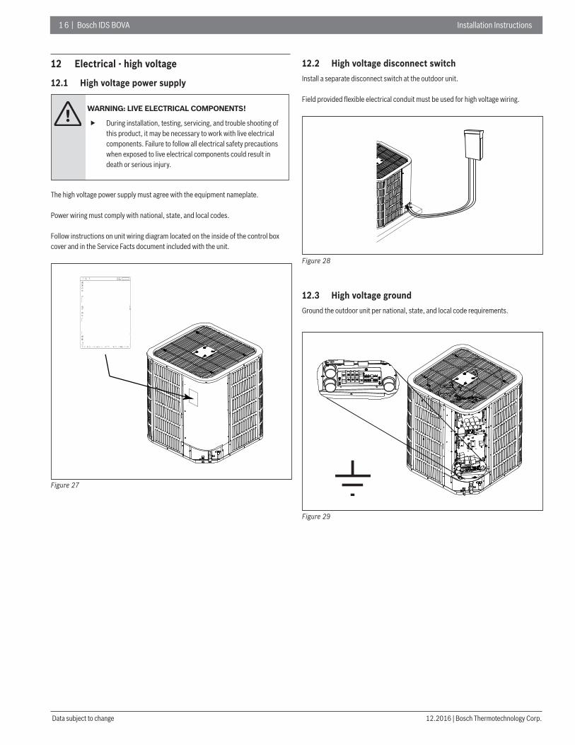
12.1 High voltage power supply
WARNING: LIVE ELECTRICAL COMPONENTS!
During installation, testing, servicing, and trouble shooting of this product, it may be necessary to work with live electrical components. Failure to follow all electrical safety precautions when exposed to live electrical components could result in death or serious injury.
The high voltage power supply must agree with the equipment nameplate.
Power wiring must comply with national, state, and local codes.
Follow instructions on unit wiring diagram located on the inside of the control box cover and in the Service Facts document included with the unit.
Figure 27
12.2 High voltage disconnect switchInstall a separate disconnect switch at the outdoor unit.
Field provided fl exible electrical conduit must be used for high voltage wiring.
Figure 28
12.3 High voltage groundGround the outdoor unit per national, state, and local code requirements.
Figure 29

Installation Instructions Bosch IDS BOVA | 17
Bosch Thermotechnology Corp. | 12.2016 Data subject to change
13 Start up
13.1 System start up1. Ensure Sections 7, 8, 9, 10, 11, 12, and 13 have been completed.
2. Set System Thermostat to OFF.
OFFDONE CANCEL
Figure 30
3. Turn on disconnect to apply power to the indoor and outdoor units.
ON
OFF
Figure 31
4. Wait one (1) hour before starting the unit if compressor crankcase heater is used and the outdoor ambient temperature is below 70 ºF.
60 MIN.
Figure 32
5. Set system thermostat to ON.
DONE CANCEL
TUE
EM HEAT
OFFCOOL
FollowingSchedule
Inside Set To
Figure 33

1 8 | Bosch IDS BOVA Installation Instructions
12.2016 | Bosch Thermotechnology Corp.Data subject to change
14 System charge adjustment
14.1 Charging: weigh-in methodWeigh-In method can be used for the Initial installation, or anytime a system charge is being replaced. weigh-In Method can also be used when power is not available to the equipment site or operating conditions (indoor/Outdoor temperatures) are not In range to verify with the subcooling charging method.
A B C
Model Factory ChargeCharge multiplier for
interconnecting refrigerant tube length
All models The data on nameplate 0.6 oz/ft
Table 4
The factory charge in the outdoor unit is suffi cient for 15 feet of standard size interconnecting liquid line.
New Installations — Calculating additional charge for lineset greater than 15 ft.
1. Total Line Length (ft) = _________(a)
2. Standard Lineset (ft) = 15 (b)
3. (a) minus (b) = _________(c)
4. Refrigerant Multiplier = 0.6 oz/ft (d)
5. Refrigerant Adder (c*d) = _________(e)*
*If lineset is less than 15 ft, (e) = 0
Sealed-System Repairs — Calculating total system charge.
1. Total Line Length (ft) = _________(a)
2. Standard Lineset (ft) = 15 (b)
3. (a) minus (b) = _________(c)
4. Refrigerant Multiplier = 0.6 oz/ft (d)
5. Refrigerant Adder (c*d) = _________(e)*
6. Factory Charge (namplate) = _________(f)
7. Total System Charge (e+f) = ________ _
*If lineset is less than 15 ft, (e) = 0
The only mode approved for validating system charge is while in Cooling "Charge Mode". Outdoor Temperature must be between 55°F and 120°F with Indoor Temperature kept between 70°F and 80°F.
14.2 Subcooling charging and refrigerant adjustment in cooling (above 55°F outdoor temp.)1. Check the outdoor ambient temperatures.
Subcooling (in cooling mode) is the only recommended method of charging above 55ºF outdoor ambient temperatures.
For outdoor ambient temperatures below 55ºF , use weigh-in charge method.Note:It is important to return in the spring or summer to accurately charge the system in the cooling mode when outdoor ambient temperature is above 55ºF.
55ºF
Outdoor Temp1
120ºF
Outdoor Temperature Above 55ºF
55ºF
Outdoor Temp2
Outdoor Temperature Below 55ºF
Figure 34
For best results the indoor temperature should be kept between 70ºF to 80ºF.
80 ºF
70ºF
Indoor Temp
Figure 35
2. Ensure Sections 7, 8, 9, 10, and 13 have been completed.
3. Stabilize the system.
After starting the system in cooling mode, short press “FORCE”button, and “ ” symbol appears in 10 minutes, operate the system for a minimum of twenty (20) minutes.
Installation Instructions Bosch IDS BOVA | 19
Bosch Thermotechnology Corp. | 12.2016 Data subject to change
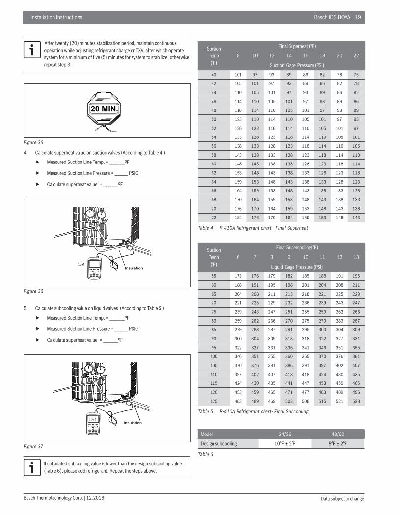
After twenty (20) minutes stabilization period, maintain continuous operation while adjusting refrigerant charge or TXV, after which operate system for a minimum of fi ve (5) minutes for system to stabilize, otherwise repeat step 3.
20 MIN.
Figure 36
4. Calculate superheat value on suction valves (According to Table 4 )
Measured Suction Line Temp. = ________ºF
Measured Suction Line Pressure = _______ PSIG
Calculate superheat value = ________ºF
Insulation107!
Figure 36
5. Calculate subcooling value on liquid valves (According to Table 5 )
Measured Suction Line Temp. = ________ºF
Measured Suction Line Pressure = _______ PSIG
Calculate superheat value = ________ºF
Insulation
Figure 37
If calculated subcooling value is lower than the design subcooling value (Table 6), please add refrigerant. Repeat the steps above.
Suction Temp (°F)
Final Superheat (°F)
8 10 12 14 16 18 20 22
Suction Gage Pressure (PSI)
40 101 97 93 89 86 82 78 75
42 105 101 97 93 89 86 82 78
44 110 105 101 97 93 89 86 82
46 114 110 105 101 97 93 89 86
48 118 114 110 105 101 97 93 89
50 123 118 114 110 105 101 97 93
52 128 123 118 114 110 105 101 97
54 133 128 123 118 114 110 105 101
56 138 133 128 123 118 114 110 105
58 143 138 133 128 123 118 114 110
60 148 143 138 133 128 123 118 114
62 153 148 143 138 133 128 123 118
64 159 153 148 143 138 133 128 123
66 164 159 153 148 143 138 133 128
68 170 164 159 153 148 143 138 133
70 176 170 164 159 153 148 143 138
72 182 176 170 164 159 153 148 143
Table 4 R-410A Refrigerant chart - Final Superheat
Suction Temp (°F)
Final Supercooling(°F)
6 7 8 9 10 11 12 13
Liquid Gage Pressure (PSI)
55 173 176 179 182 185 188 191 195
60 188 191 195 198 201 204 208 211
65 204 208 211 215 218 221 225 229
70 221 225 229 232 236 239 243 247
75 239 243 247 251 255 259 262 266
80 259 262 266 270 275 279 283 287
85 279 283 287 291 295 300 304 309
90 300 304 309 313 318 322 327 331
95 322 327 331 336 341 346 351 355
100 346 351 355 360 365 370 376 381
105 370 376 381 386 391 397 402 407
110 397 402 407 413 418 424 430 435
115 424 430 435 441 447 453 459 465
120 453 459 465 471 477 483 489 496
125 483 489 469 502 508 515 521 528
Table 5 R-410A Refrigerant chart- Final Subcooling
Model 24/36 48/60
Design subcooling 10°F ± 2°F 8°F ± 2°F
Table 6

2 0 | Bosch IDS BOVA Installation Instructions
12.2016 | Bosch Thermotechnology Corp.Data subject to change
6. Adjust refrigerant level to attain proper gage pressure.
Add refrigerant if the design subcooling is lower than the chart value.
Connect gages to refrigerant bottle and unit as illustrated (Fig 38).
Purge all hoses.
Open bottle.
Stop adding refrigerant when subcooling. matches the charging chart (Table 5) Final Subcooling value.
Recover refrigerant if the design subcooling is lower than the chart value.
Figure 38
7. Stabilize the system.
Wait 5 minutes for the system condition to stabilize between adjustments.
When the subcooling match the chart, the system is properly charged.
Remove gages.
Replace service port caps to prevent leaks. Tighten finger tight plus an additional 1/6 turn.
20 MIN.
Figure 39
8. Record System Information for reference (Table 7).Record system pressures and temperatures after charging is complete.
Description Value
Outdoor model number
Measured Outdoor Ambient °F
Measured Indoor Ambient °F
Measured Liquid Line Temp °F
Measured Suction Line Temp °F
Liquid Gage Pressure PSIG
Suction Gage Pressure PSIG
Table 7

Installation Instructions Bosch IDS BOVA | 21
Bosch Thermotechnology Corp. | 12.2016 Data subject to change
15 System operation and troubleshooting
15.1 Control logic description
The variable speed system adopts the same 24VAC control as any conventional Heat Pump.
The compressor’s speed is controlled based on coil pressures monitored by pressure transducer. To insure stable and adequate capacity, the compressor speed will modulate relative to evaporator pressure during cooling operation and relative to condensing pressure during heating operation. The target pressure can auto-matically adjust based on compressor operation so optimal capacity can be achieved. Target pressure can manually be adjusted (SW4) to achieve improved dehumidification and capacity demands.
ON
OFF 1 2 3 4
Figure 40
Switch Description
SW4-1 Not used
SW4-2 Not used
SW4-3ON Adaptive capacity output disable
OFF Adaptive capacity output enable
SW4-4ON Accelerated cooling/heating
OFF Normally cooling/heating
Table 8
15.2 Sensors (thermistors/pressure transducer)
t3 = Outdoor Coil Temperature (Table 1) — High/Low temperature protection — Outdoor fan control (cooling mode) — Defrost control (heating mode) — Ambient Temperature forecast
T4 = Ambient Temperature (Table 1) — Operating condition permission — Defrosting condition permission — Outdoor fan control (heating mode)
T5 = Compressor Discharge Temperature (Table 2) — High/Low temperature protection — Electronic Expansion Valve (EEV) control (ODU)
TF = IPM Radiator Temperature) (Table 2) — Inverter High Temperature Protection
Pressure transducer (Table 3) — Operating speed control — Electronic Expansion Valve (EEV) control (ODU) — High pressure protection (heating mode) — Low pressure protection (cooling mode)
15.3 Defrost description
The Demand Defrost Control (DDC) monitors the ODU coil temperature using thermistor (T3). A second thermistor (T4) monitors outdoor ambient temperature. Based on these parameters, as well as accumulative run time and high pressure, the DDC calculates proper initiation of defrost.
The following three conditions are required to enter defrost:
1. Outdoor coil temperature T3 < 34°F and a corresponding minimum outdoor ambient temperature is met.
2. After “Minimum Run Time” (MRT) is achieved. MRT is based on outdoor ambient temperature (T4), for example:
— MRT is 4 hours when: T4 < 23°F — MRT is 2 hours when: 23°F ≤ T4 < 42°F
3. After the high pressure saturation temperature drops below 82°F for 20 minutes.
Defrost will terminate once outdoor coil temperature (T3) reaches 64°F for a period of 1 minute or defrost time has exceeded 8 minutes.
Defrost Termination Settings (SW5) offers different defrost termination options for enhanced defrost for different geographical &/or outdoor conditions.
ON
OFF 1 2
SW5
Figure 41
Defrosting choice SW5-1 SW5-2 Remarks
ONOperating time is reduced by 10%
Defrosting extended for 60 seconds
OFF Normal Normal Default
Remarks Enter defrost Quit defrost
Table 8
2 2 | Bosch IDS BOVA Installation Instructions
12.2016 | Bosch Thermotechnology Corp.Data subject to change
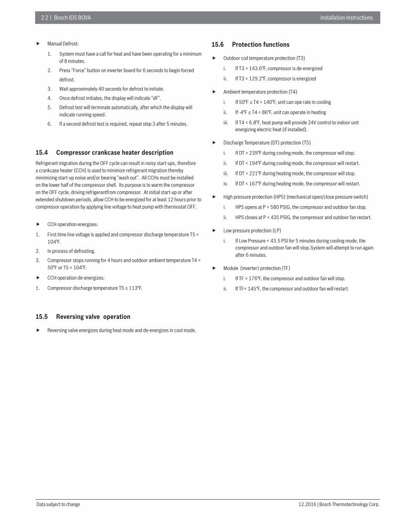
Manual Defrost:
1. System must have a call for heat and have been operating for a minimum of 8 minutes.
2. Press “Force” button on inverter board for 6 seconds to begin forced
defrost.
3. Wait approximately 40 seconds for defrost to initiate.
4. Once defrost initiates, the display will indicate “dF”.
5. Defrost test will terminate automatically, after which the display will indicate running speed.
6. If a second defrost test is required, repeat step 3 after 5 minutes.
15.4 Compressor crankcase heater descriptionRefrigerant migration during the OFF cycle can result in noisy start-ups, therefore a crankcase heater (CCH) is used to minimize refrigerant migration thereby minimizing start-up noise and/or bearing “wash out”. All CCHs must be installed on the lower half of the compressor shell. Its purpose is to warm the compressor on the OFF cycle, driving refrigerantfrom compressor. At initial start-up or after extended shutdown periods, allow CCH to be energized for at least 12 hours prior to compressor operation by applying line voltage to heat pump with thermostat OFF.
CCH operation energizes:
1. First time line voltage is applied and compressor discharge temperature T5 < 104°F.
2. In process of defrosting.
3. Compressor stops running for 4 hours and outdoor ambient temperature T4 < 50°F or T5 < 104°F.
CCH operation de-energizes:
1. Compressor discharge temperature T5 ≥ 113°F.
15.5 Reversing valve operation
Reversing valve energizes during heat mode and de-energizes in cool mode.
15.6 Protection functions
Outdoor coil temperature protection (T3)
i. If T3 > 143.6°F, compressor is de-energized
ii. If T3 < 129.2°F, compressor is energized
Ambient temperature protection (T4)
i. If 50°F ≤ T4 < 140°F, unit can ope rate in cooling
ii. If -4°F ≤ T4 < 86°F, unit can operate in heating
iii. If T4 < 6.8°F, heat pump will provide 24V control to indoor unit energizing electric heat (if installed).
Discharge Temperature (DT) protection (T5)
i. If DT > 239°F during cooling mode, the compressor will stop.
ii. If DT < 194°F during cooling mode, the compressor will restart.
iii. If DT > 221°F during heating mode, the compressor will stop.
iv. If DT < 167°F during heating mode, the compressor will restart.
High pressure protection (HPS) (mechanical open/close pressure switch)
i. HPS opens at P > 580 PSIG, the compressor and outdoor fan stop.
ii. HPS closes at P < 435 PSIG, the compressor and outdoor fan restart.
Low pressure protection (LP)
i. If Low Pressure < 43.5 PSI for 5 minutes during cooling mode, the compressor and outdoor fan will stop.System will attempt to run again after 6 minutes.
Module (inverter) protection (TF)
i. If TF > 176°F, the compressor and outdoor fan will stop.
ii. If TF< 145°F, the compressor and outdoor fan will restart.
Installation Instructions Bosch IDS BOVA | 23
Bosch Thermotechnology Corp. | 12.2016 Data subject to change
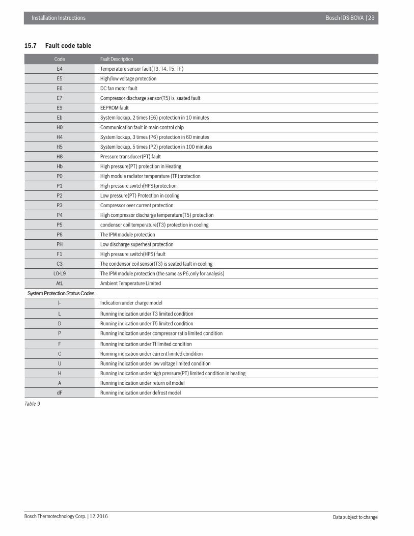
15.7 Fault code table
Code Fault Description
E4 Temperature sensor fault(T3, T4, T5, TF)
E5 High/low voltage protection
E6 DC fan motor fault
E7 Compressor discharge sensor(T5) is seated fault
E9 EEPROM fault
Eb System lockup, 2 times (E6) protection in 10 minutes
H0 Communication fault in main control chip
H4 System lockup, 3 times (P6) protection in 60 minutes
H5 System lockup, 5 times (P2) protection in 100 minutes
H8 Pressure transducer(PT) fault
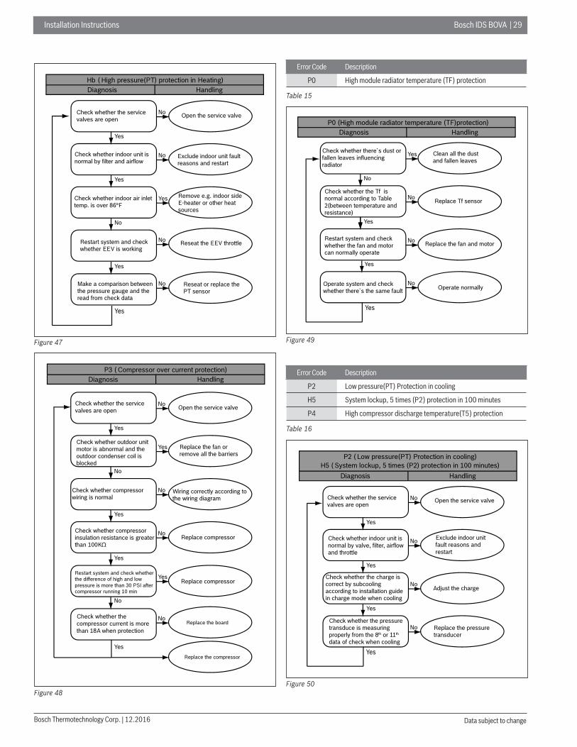
Hb High pressure(PT) protection in Heating
P0 High module radiator temperature (TF)protection
P1 High pressure switch(HPS)protection
P2 Low pressure(PT) Protection in cooling
P3 Compressor over current protection
P4 High compressor discharge temperature(T5) protection
P5 condensor coil temperature(T3) protection in cooling
P6 The IPM module protection
PH Low discharge superheat protection
F1 High pressure switch(HPS) fault
C3 The condensor coil sensor(T3) is seated fault in cooling
L0-L9 The IPM module protection (the same as P6,only for analysis)
AtL Ambient Temperature Limited
System Protection Status Codes
Indication under charge model
L Running indication under T3 limited condition
D Running indication under T5 limited condition
P Running indication under compressor ratio limited condition
F Running indication under Tf limited condition
C Running indication under current limited condition
U Running indication under low voltage limited condition
H Running indication under high pressure(PT) limited condition in heating
A Running indication under return oil model
dF Running indication under defrost model
Table 9

2 4 | Bosch IDS BOVA Installation Instructions
12.2016 | Bosch Thermotechnology Corp.Data subject to change
15.8 Parameter point check table
To display system parameters, press the “Check” button to index through the series of parameters available. The first time you press on the “Check” button, it will display the sequence, and after 1 second it will display the value of the parameter. If you press the “Check” button again, it will display the next sequence.
Normal Status, last two digits will display under following conditions
i. Unit not operating(Standby Mode); “outdoor ambient temperature”.ii. Unit operating; displays “compressor operating frequency”.
After 20 seconds on same parameter, display will revert back to normal status.
If a system protection is active, first digit will display “status code”.
No. Point check content Example Remark
0 Outdoor unit capacity H3 H3=Heat Pump 3 ton
1 Outdoor unit mode 20 standby,2 cooling,3 heating
2 Outdoor unit set compressor speed
3 Opening of EEV Actual value
4 T3(outdoor coil temp.) (°F )
5 T4 (outdoor ambient temp.) (°F )
6 T5(compressor discharge temp.) (°F )
7 Reserved
8 Te (evaporating temp.) (°F )
9 Tc (condensing temp.) (°F )
10 Tf (module temp.) (°F )
11 Pe (evaporating pressure) (PSI)
12 Pc (evaporating pressure) (PSI)
13 Compressor discharge superheat (°F ) Actual value
14 Reserved
15 Reserved
16 Compressor current (A)
17 Reserved
18 Fan speed
19 Reserved
20 Reserved
21Compressor discharge superheat (only useful for heating mode) (°F ) Target Value
22 Reserved
23 Last Fault Code
24 Software version
25 Remark“--”
Table 10

Installation Instructions Bosch IDS BOVA | 25
Bosch Thermotechnology Corp. | 12.2016 Data subject to change
15.9 Control board overviewsFor 2436 model
EEPROM chip
65
78
9
10
11
121317
19
20
21
22 23
1
2
3
14
4
151618
24
CUT OFF J2 JUMP FOR 24K MODEL.THE FACTORY SETTING FOR 36K MODEL,
Figure 42
* The photo is just for reference,actual unit will verify.
No. Function description No. Function description
1 Compressor wiring terminal 13 Temp. controller connecting port
2 Reactor wiring terminal(connect a reactor between 2 and 3 ) 14 Function dial code SW4
3 Reactor wiring terminal(connect a reactor between 2 and 3 ) 15 Spot check button
4 Defrosting function dial codeSW5 16 Forced operation button
5 Pressure transducer port 17 Reserved
6 Air discharge temp.sensor port 18 Digital tube display
7 Outdoor temp.sensor port(HP only) 19 Fan control port
8 Condenser temp.sensor port 20 Crankcase heating zone control terminal
9 Radiator temp.sensor port 21 Short wire
10 High pressure switch port 22 Power supply connecting terminal
11 EEV drive port(HP only) 23 Power supply connecting terminal
12 Reversing valve port 24 Indicator lamp
Table 11

2 6 | Bosch IDS BOVA Installation Instructions
12.2016 | Bosch Thermotechnology Corp.Data subject to change
For 4860 model
Main control board
CUT OFF J2 JUMP FOR 24K MODEL.THE FACTORY SETTING FOR 36K MODEL,
15
21
18
19
1614 20 2217
13
12 1011
8
9
1
2
34
56
7
EEPROM chip
Figure 43
* The photo is just for reference,actual unit will verify.
No. Function description No. Function description
1 EEV driving port (HP only) 12 The voltage between 12 and 13 is 380Vdc (Compressor is running )
2 High pressure switch port 13 The voltage between 12 and 13 is 380Vdc (Compressor is running )
3 Radiator temp. sensor port 14 DC motor control port
4 Condenser temp.sensor port 15 Nixie tube display
5 Outdoor temp.sensor port (HP only) 16 Reserved
6 Air discharge temp.sensor port 17 Defrosting functiondialcode SW5
7 Pressure transducer 18 Function dial code SW4
8 Connection wire port between main boards 19 Point check button
9 DC motor driving source (15V-P2) 20 Temp. controller connection port
10 The voltage between 10 and 11 is 380Vdc (Compressor is running ) 21 Forced operation button
11 The voltage between 10 and 11 is 380Vdc (Compressor is running ) 22 4-way valve port (HP only)
Table 12
Installation Instructions Bosch IDS BOVA | 27
Bosch Thermotechnology Corp. | 12.2016 Data subject to change
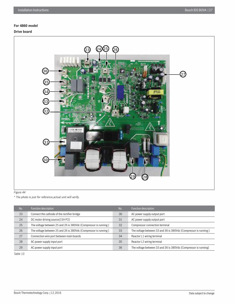
For 4860 model
Drive board
33
36
34
35
23 24 25 26
32
27
30
31
29 28
Figure 44
* The photo is just for reference,actual unit will verify.
No. Function description No. Function description
23 Connect the cathode of the rectifi er bridge 30 AC power supply output port
24 DC motor driving source(15V-P2) 31 AC power supply output port
25 The voltage between 25 and 26 is 380Vdc (Compressor is running ) 32 Compressor connection terminal
26 The voltage between 25 and 26 is 380Vdc (Compressor is running ) 33 The voltage between 33 and 36 is 380Vdc (Compressor is running )
27 Connection wire port between main boards 34 Reactor L1 wiring terminal
28 AC power supply input port 35 Reactor L2 wiring terminal
29 AC power supply input port 36 The voltage between 33 and 36 is 380Vdc (Compressor is running)
Table 13
2 8 | Bosch IDS BOVA Installation Instructions
12.2016 | Bosch Thermotechnology Corp.Data subject to change
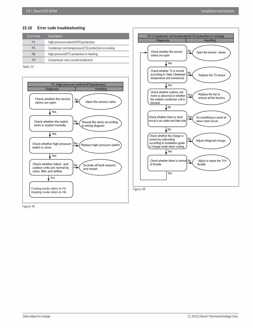
15.10 Error code troubleshooting
Error Code Description
P1 High pressure switch(HPS)protection
P5 Condenser coil temperature(T3) protection in cooling
Hb High pressure(PT) protection in Heating
P3 Compressor over current protection
Table 14
P1 (High pressure switch(HPS)protection)Diagnosis Handling
Check whether the service valves are open
Yes
Check whether the switch wires is seated normally
Yes
Check whether high pressure switch is close
Yes
Check whether indoor and outdoor units are normal by valve, filter and airflow
Open the service valveNo
Reseat the wires according to wiring diagram
No
Replace high pressure switchNo
Exclude all fault reasons and restart
No
Yes
Cooling mode refers to P5Heating mode refers to Hb
Figure 45
P5 ( Condenser coil temperature(T3) protection in cooling)Diagnosis Handling
Check whether the service valves are open
Yes
Check whether T3 is normal according to Table 1(between temperature and resistance)
Yes
Check whether outdoor unit motor is abnormal or whether the outdoor condenser coil is blocked
No
Check whether there is short circuit in air outlet and inlet side
No
Check whether the charge is correct by subcooling according to installation guide in charge mode when cooling
Yes
Yes
Check whether there is normal of throttle
Open the service valvesNo
Replace the T3 sensorNo
Replace the fan or remove all the barriers
Do something to avoid air return short circuit
Yes
Adjust refrigerant chargeNo
Yes
Adjust or repair the TXV throttle
No
Figure 46
Installation Instructions Bosch IDS BOVA | 29
Bosch Thermotechnology Corp. | 12.2016 Data subject to change
Hb ( High pressure(PT) protection in Heating)Diagnosis Handling
Check whether the service valves are open
Yes
Check whether indoor unit is normal by filter and airflow
Yes
Check whether indoor air inlet temp. is over 86°F
No
Restart system and check whether EEV is working
Yes
Make a comparison between the pressure gauge and the read from check data
Open the service valveNo
Exclude indoor unit fault reasons and restart
No
Remove e.g. indoor side E-heater or other heat sources
Yes
Reseat or replace the PT sensor
No
Reseat the EEV throttleNo
Yes
Figure 47
P3 ( Compressor over current protection)Diagnosis Handling
Check whether the service valves are open
Yes
Check whether outdoor unit motor is abnormal and the outdoor condenser coil is blocked
No
No
Check whether compressor wiring is normal
Yes
Check whether compressor insulation resistance is greater than 100KΩ
Yes
Restart system and check whether the difference of high and low pressure is more than 30 PSI after compressor running 10 min
Yes
Check whether the compressor current is more than 18A when protection
Open the service valveNo
Replace the fan or remove all the barriers
Yes
Wiring correctly according to the wiring diagram
Replace compressor
No
YesReplace compressor
No
Replace the board
Replace the compressor
No
Figure 48
Error Code Description
P0 High module radiator temperature (TF) protection
Table 15
P0 (High module radiator temperature (TF)protection)Diagnosis Handling
Check whether there`s dust or fallen leaves influencing radiator
No
Check whether the Tf is normal according to Table 2(between temperature and resistance)
Yes
Clean all the dust and fallen leaves
Yes
Replace Tf sensor
Restart system and check whether the fan and motor can normally operate
Replace the fan and motor
No
No
Yes
Operate system and check whether there`s the same fault Operate normally
No
Yes
Figure 49
Error Code Description
P2 Low pressure(PT) Protection in cooling
H5 System lockup, 5 times (P2) protection in 100 minutes
P4 High compressor discharge temperature(T5) protection
Table 16
P2 ( Low pressure(PT) Protection in cooling)H5 ( System lockup, 5 times (P2) protection in 100 minutes)
Diagnosis Handling
Check whether indoor unit is normal by valve, filter, airflow and throttle
Yes
Check whether the service valves are open
Yes
Check whether the charge is correct by subcooling according to installation guide in charge mode when cooling
Yes
Check whether the pressure transduce is measuring properly from the 8th or 11th data of check when cooling
Exclude indoor unit fault reasons and restart
No Open the service valve
No
Adjust the chargeNo
Replace the pressure transducer
No
Yes
Figure 50
3 0 | Bosch IDS BOVA Installation Instructions
12.2016 | Bosch Thermotechnology Corp.Data subject to change
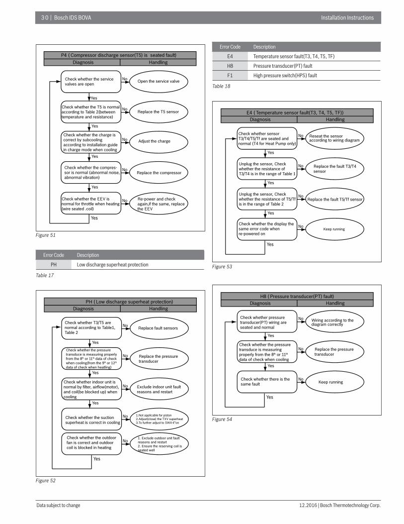
P4 ( Compressor discharge sensor(T5) is seated fault)Diagnosis Handling
Check whether the service valves are open
Yes
Check whether the T5 is normal according to Table 2(between temperature and resistance)
Yes
Check whether the charge is correct by subcooling according to installation guide in charge mode when cooling
Yes
Check whether the compres-sor is normal (abnormal noise, abnormal vibration)
Yes
Check whether the EEV is normal for throttle when heating (wire seated .coil)
Open the service valveNo
Replace the T5 sensorNo
Adjust the chargeNo
Replace the compressor No
Re-power and check again,if the same, replace the EEV
No
Yes
Figure 51
Error Code Description
PH Low discharge superheat protection
Table 17
PH ( Low discharge superheat protection)Diagnosis Handling
Yes
Check whether the pressure transduce is measuring properly from the 8th or 11th data of check when cooling(from the 9th or 12th data of check when heatling)
Yes
Yes
Check whether the suction superheat is correct in cooling
Check whether indoor unit is normal by filter, airflow(motor), and coil(be blocked up) when cooling
Check whether the outdoor fan is correct and outdoor coil is blocked in heating
No
Replace the pressure transducer
No
No Exclude indoor unit fault reasons and restart
No
1.Not applicable for piston2.Adjust(close) the TXV superheat3.To further adjust to SW4-4”on
No
1. Exclude outdoor unit fault reasons and restart2. Ensure the reserving coil is seated well
Check whether T3/T5 are normal according to Table1, Table 2
Replace fault sensors
Yes
Figure 52
Error Code Description
E4 Temperature sensor fault(T3, T4, T5, TF)
H8 Pressure transducer(PT) fault
F1 High pressure switch(HPS) fault
Table 18
E4 ( Temperature sensor fault(T3, T4, T5, TF))Diagnosis Handling
Check whether sensor T3/T4/T5/Tf are seated and normal (T4 for Heat Pump only)
Yes
Unplug the sensor, Check whether the resistance of T3/T4 is in the range of Table 1
Yes
Unplug the sensor, Check whether the resistance of T5/Tf is in the range of Table 2
Yes
Check whether the display the same error code when re-powered on
Reseat the sensor according to wiring diagram
No
Replace the fault T3/T4 sensor
No
Replace the fault T5/Tf sensorNo
Keep runningNo
Yes
Figure 53
H8 ( Pressure transducer(PT) fault)Diagnosis Handling
Yes
Yes
Check whether there is the same fault
No
No
Keep runningNo
Check whether pressure transducer(PT) wiring are seated and normal
Wiring according to the diagram correctly
Check whether the pressure transduce is measuring properly from the 8th or 11th data of check when cooling
Replace the pressure transducer
Yes
Figure 54
Installation Instructions Bosch IDS BOVA | 31
Bosch Thermotechnology Corp. | 12.2016 Data subject to change
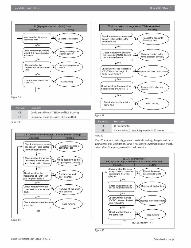
F1 ( High pressure switch(HPS) fault)Diagnosis Handling
Yes
Yes
Check whether the resistance of HPS is close to 0KΩ
No
No
Replace high pressure switch
No
Check whether the service valves are open Open the service valve
Check whether high pressure switch(HPS) wiring is seated and normal
Wiring according to the diagram correctly
Yes
Yes
Check whether there is the same fault Keep runningNo
Figure 55
Error Code Description
C3 Condenser coil sensor(T3) is seated fault in cooling
E7 Compressor discharge sensor(T5) is seated fault
Table 19
C3 Condenser coil sensor(T3) is seated fault in cooling)Diagnosis Handling
Yes
Check whether the sensor ofT3/T4/HPS are connectedaccording to wiring diagram
Yes
Check whether theresistance of T3/T4 is inthe range of Table 1
No
Wiring according to thewiring diagram correctly
No
Replace the faultT3/T4 sensor
No
Check whether condensercoil sensor(T3) is seatedto the condenser coil
Reseat the sensor tocondenser coil
Yes
Check whether there is thesame fault Keep running
No
Yes
Check whether there areother heat sources aroundT3/T4
Remove all the otherheat sources
No
Yes
Figure 56
E7 Compressor discharge sensor(T5) is seated fault)Diagnosis Handling
Yes
Check whether the sensor ofT3/T5 are connected accord-ing to wiring diagram
Yes
Check whether the resistanceof T3/T5 is in the range ofTable 1 and Table 2
Yes
Check whether there are otherheat sources around T3/T5
No
Wiring according to thewiring diagram correctly
No
Replace the fault T3/T5 sensorNo
Yes
Check whether there is thesame fault Keep runningYes
Remove all the other heatsources
No
Check whether condenser coilsensor(T5) is seated to thecondenser coil
Reseat the sensor todischarge tube
Figure 57
Error Code Description
E6 DC fan motor fault
Eb System lockup, 2 times (E6) protection in 10 minutes
Table 20
When E6 appears occasionally, you don`t need to do anything, the system will restart automatically after 6 minutes, of course, if you check the system of running, it will be better. When Eb appears, you need to check the motor.
E6 DC fan motor fault)Eb System lockup, 2 times (E6) protection in 10 minutes)
Diagnosis Handling
Check whether DC motorwiring is reliably connectedaccording to the wiringdiagram
Yes
Check whether outdoorcoil air return is blocked
Yes
Check whether there is15V DC between the testpoint P8 and P2
Yes
Check whether there isthe same fault
Reseat the wiringaccording to wiring
No
Remove all the barriersNo
Replace the control boardNo
Keep running
NOTE: Just for 4T/5T
No
Yes
Figure 58

3 2 | Bosch IDS BOVA Installation Instructions
12.2016 | Bosch Thermotechnology Corp.Data subject to change
Error Code Description
E9 EEPROM fault
H0 Communication fault in main control chip
E5 High/low voltage protection
Table 21
When E9/H0/E5 appears occasionally, and the system restart to run normally after power supply again, you don`t need to do anything. Otherwise, you need to check the system.
E9 (EEPROM fault)Diagnosis Handling
Check whether the wiring isconnected normally
Yes
Restart to power on andcheck whether it is normal
Reseat the wiring accordingto wiring diagram
No
Reseat the wiring accordingto wiring diagram
Replace the control board
Yes The fault is still
You need do nothing. Perhaps thisfault is caused by accident, such asstrong interference form electricitygrid. System will recovery whenelectricity grid is normal
No
Figure 59
H0 ( Communication fault in main control chip)Diagnosis Handling
Yes
You need do nothing. Perhaps this fault is caused by accident, such as strong interference form electricity grid. System will recovery when electricity grid is normal
No
5T: Replace the control board
5T: Replace the drive board
No
Yes The fault is still
The fault is still
No
Check whether the wiring is connected normally
Reseat the wiring according to wiring diagram
Restart to power on and check whether it is normal
3T: Replace the control board5T: Reseat the communication wire
Figure 60
E5 ( High/low voltage protection)Diagnosis Handling
Yes
Check whether the power wires are connected firmly, whether the power supply wires diameter meets the requirements from the manufacture
Yes
Restart to the power supply and check whether the compressor operates normally
Yes
Check whether there are high voltage equipment nearby
Yes
No
No
Replace the power supply wires or connect the power supply wires well
No
Replace the drive boardNo
Replace the drive board
Yes Separate high-power equipment and power supply
No
Check whether the power supply voltage is between 187-253V
Make sure the power supply is within correct range
Gauge and check whether there is 380V DC between the terminals P2 and P4 when compressor is running
Figure 61
Installation Instructions Bosch IDS BOVA | 33
Bosch Thermotechnology Corp. | 12.2016 Data subject to change
Error Code Description
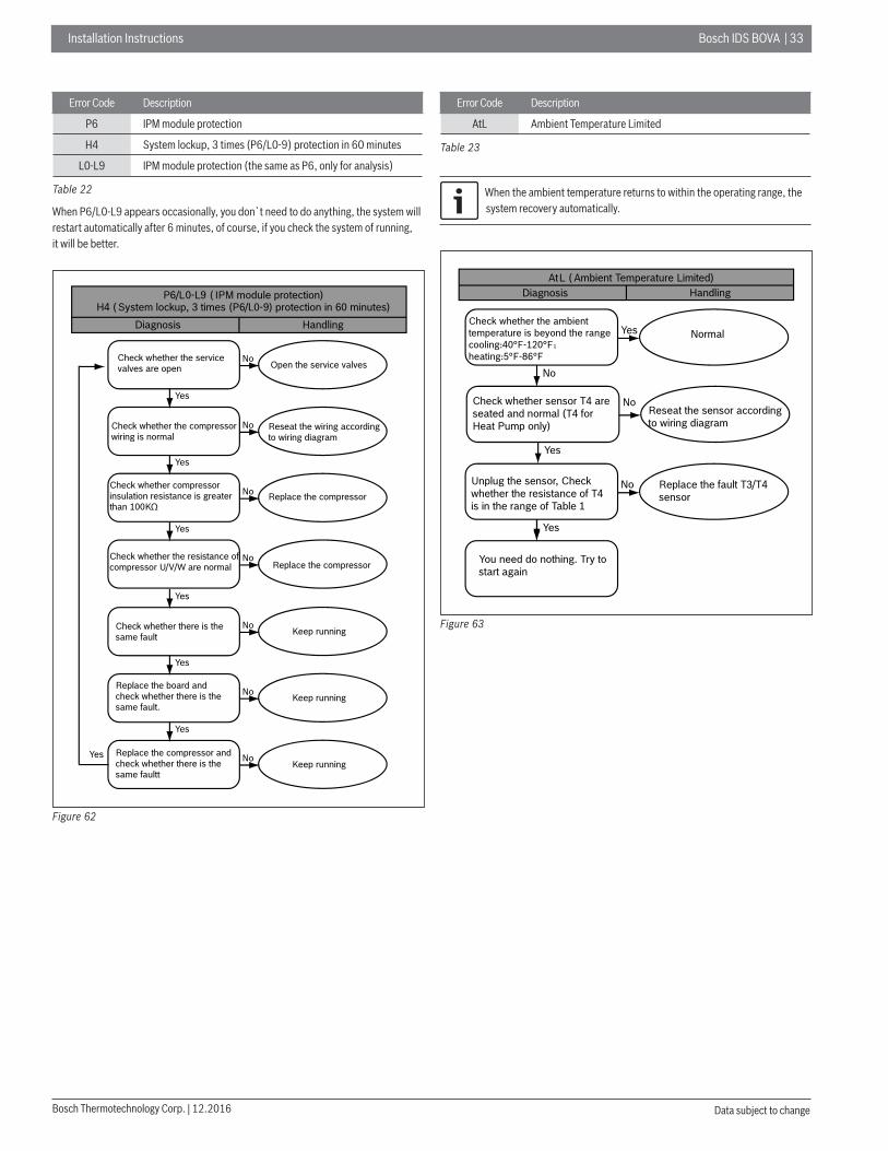
P6 IPM module protection
H4 System lockup, 3 times (P6/L0-9) protection in 60 minutes
L0-L9 IPM module protection (the same as P6, only for analysis)
Table 22
When P6/L0-L9 appears occasionally, you don`t need to do anything, the system will restart automatically after 6 minutes, of course, if you check the system of running, it will be better.
P6/L0-L9 ( IPM module protection)H4 ( System lockup, 3 times (P6/L0-9) protection in 60 minutes)
Diagnosis Handling
Check whether the service valves are open
Yes
Yes
Check whether compressor insulation resistance is greater than 100KΩ
Yes
Check whether the resistance of compressor U/V/W are normal
Yes
Check whether there is the same fault
Open the service valvesNo
No
No
Keep runningNo
Yes
Replace the board and check whether there is the same fault.
Keep runningNo
Yes
Yes Replace the compressor and check whether there is the same faultt
Keep runningNo
Replace the compressorNo
Check whether the compressor wiring is normal
Reseat the wiring according to wiring diagram
Replace the compressor
Figure 62
Error Code Description
AtL Ambient Temperature Limited
Table 23
When the ambient temperature returns to within the operating range, the system recovery automatically.
AtL ( Ambient Temperature Limited)Diagnosis Handling
No
Yes
No
Yes
No
Yes
Check whether the ambient temperature is beyond the rangecooling:40°F-120°Fheating:5°F-86°F
Normal
Check whether sensor T4 are seated and normal (T4 for Heat Pump only)
Unplug the sensor, Check whether the resistance of T4 is in the range of Table 1
You need do nothing. Try to start again
Reseat the sensor according to wiring diagram
Replace the fault T3/T4 sensor
Figure 63
3 4 | Bosch IDS BOVA Installation Instructions
12.2016 | Bosch Thermotechnology Corp.Data subject to change
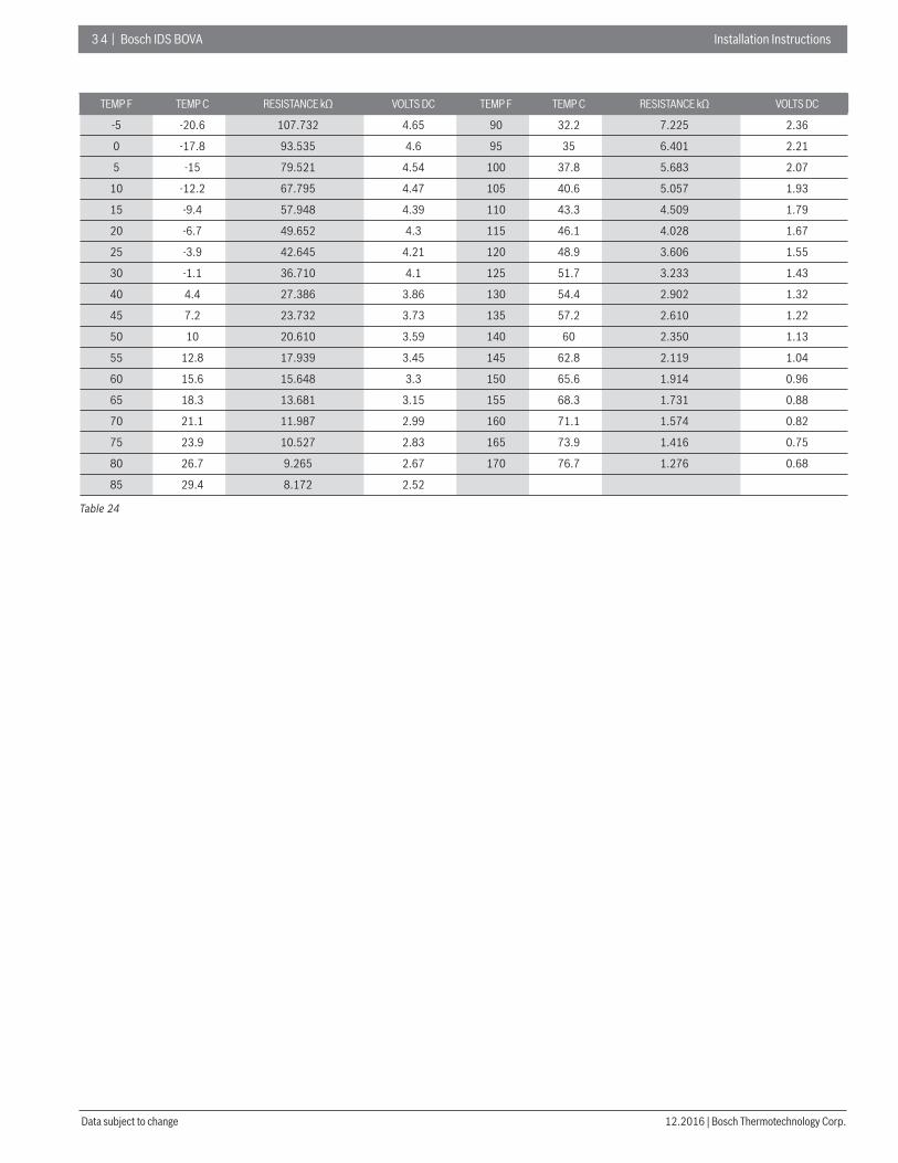
TEMP F TEMP C RESISTANCE kΩ VOLTS DC TEMP F TEMP C RESISTANCE kΩ VOLTS DC
-5 -20.6 107.732 4.65 90 32.2 7.225 2.36
0 -17.8 93.535 4.6 95 35 6.401 2.21
5 -15 79.521 4.54 100 37.8 5.683 2.07
10 -12.2 67.795 4.47 105 40.6 5.057 1.93
15 -9.4 57.948 4.39 110 43.3 4.509 1.79
20 -6.7 49.652 4.3 115 46.1 4.028 1.67
25 -3.9 42.645 4.21 120 48.9 3.606 1.55
30 -1.1 36.710 4.1 125 51.7 3.233 1.43
40 4.4 27.386 3.86 130 54.4 2.902 1.32
45 7.2 23.732 3.73 135 57.2 2.610 1.22
50 10 20.610 3.59 140 60 2.350 1.13
55 12.8 17.939 3.45 145 62.8 2.119 1.04
60 15.6 15.648 3.3 150 65.6 1.914 0.96
65 18.3 13.681 3.15 155 68.3 1.731 0.88
70 21.1 11.987 2.99 160 71.1 1.574 0.82
75 23.9 10.527 2.83 165 73.9 1.416 0.75
80 26.7 9.265 2.67 170 76.7 1.276 0.68
85 29.4 8.172 2.52
Table 24
Installation Instructions Bosch IDS BOVA | 35
Bosch Thermotechnology Corp. | 12.2016 Data subject to change
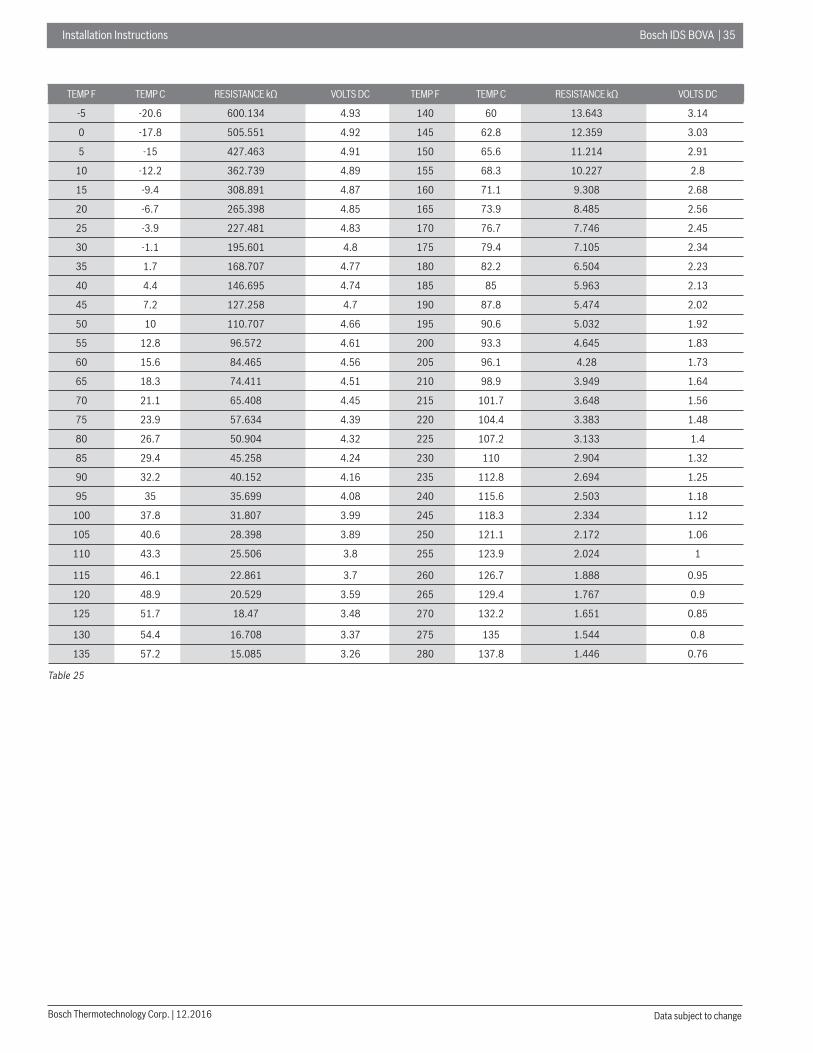
TEMP F TEMP C RESISTANCE kΩ VOLTS DC TEMP F TEMP C RESISTANCE kΩ VOLTS DC
-5 -20.6 600.134 4.93 140 60 13.643 3.14
0 -17.8 505.551 4.92 145 62.8 12.359 3.03
5 -15 427.463 4.91 150 65.6 11.214 2.91
10 -12.2 362.739 4.89 155 68.3 10.227 2.8
15 -9.4 308.891 4.87 160 71.1 9.308 2.68
20 -6.7 265.398 4.85 165 73.9 8.485 2.56
25 -3.9 227.481 4.83 170 76.7 7.746 2.45
30 -1.1 195.601 4.8 175 79.4 7.105 2.34
35 1.7 168.707 4.77 180 82.2 6.504 2.23
40 4.4 146.695 4.74 185 85 5.963 2.13
45 7.2 127.258 4.7 190 87.8 5.474 2.02
50 10 110.707 4.66 195 90.6 5.032 1.92
55 12.8 96.572 4.61 200 93.3 4.645 1.83
60 15.6 84.465 4.56 205 96.1 4.28 1.73
65 18.3 74.411 4.51 210 98.9 3.949 1.64
70 21.1 65.408 4.45 215 101.7 3.648 1.56
75 23.9 57.634 4.39 220 104.4 3.383 1.48
80 26.7 50.904 4.32 225 107.2 3.133 1.4
85 29.4 45.258 4.24 230 110 2.904 1.32
90 32.2 40.152 4.16 235 112.8 2.694 1.25
95 35 35.699 4.08 240 115.6 2.503 1.18
100 37.8 31.807 3.99 245 118.3 2.334 1.12
105 40.6 28.398 3.89 250 121.1 2.172 1.06
110 43.3 25.506 3.8 255 123.9 2.024 1
115 46.1 22.861 3.7 260 126.7 1.888 0.95
120 48.9 20.529 3.59 265 129.4 1.767 0.9
125 51.7 18.47 3.48 270 132.2 1.651 0.85
130 54.4 16.708 3.37 275 135 1.544 0.8
135 57.2 15.085 3.26 280 137.8 1.446 0.76
Table 25

3 6 | Bosch IDS BOVA Installation Instructions
12.2016 | Bosch Thermotechnology Corp.Data subject to change
NSK-BD035I V= (7.9*PSIG*10-3)+0.5
No. VPe/Pc
No. VPe/Pc
No. VPe/Pc
PSIG PSIG PSIG
1 0.69 24.4 56 1.37 110.6 111 2.54 258.5
2 0.7 26.0 57 1.39 112.5 112 2.56 262.0
3 0.72 27.7 58 1.4 114.5 113 2.59 265.6
4 0.73 29.4 59 1.42 116.5 114 2.62 269.2
5 0.75 31.2 60 1.43 118.6 115 2.65 272.8
6 0.76 33.1 61 1.45 120.6 116 2.68 276.5
7 0.78 35.0 62 1.47 122.7 117 2.71 280.2
8 0.79 37.0 63 1.48 124.8 118 2.74 284.0
9 0.81 39.0 64 1.5 127.0 119 2.77 287.8
10 0.82 41.1 65 1.52 129.1 120 2.8 291.6
11 0.84 43.2 66 1.53 131.3 121 2.83 295.5
12 0.85 44.3 67 1.55 133.5 122 2.86 299.3
13 0.86 45.4 68 1.57 135.8 123 2.89 303.3
14 0.87 46.6 69 1.59 138.0 124 2.92 307.2
15 0.88 47.7 70 1.61 140.3 125 2.95 311.3
16 0.89 48.9 71 1.62 142.6 126 2.98 315.3
17 0.89 50.0 72 1.64 145.0 127 3.02 319.4
18 0.9 51.2 73 1.66 147.3 128 3.05 323.5
19 0.91 52.4 74 1.68 149.7 129 3.08 327.7
20 0.92 53.7 75 1.7 152.1 130 3.12 331.9
21 0.93 54.9 76 1.72 154.6 131 3.15 336.1
22 0.94 56.2 77 1.74 157.1 132 3.18 340.4
23 0.95 57.5 78 1.76 159.6 133 3.22 344.7
24 0.96 58.8 79 1.78 162.1 134 3.25 349.0
25 0.97 60.1 80 1.8 164.6 135 3.29 353.4
26 0.98 61.4 81 1.82 167.2 136 3.32 357.9
27 0.99 62.8 82 1.84 169.8 137 3.36 362.4
28 1.01 64.1 83 1.86 172.5 138 3.39 366.9
29 1.02 65.5 84 1.88 175.1 139 3.43 371.4
30 1.03 66.9 85 1.9 177.8 140 3.46 376.0
31 1.04 68.4 86 1.92 180.5 141 3.5 380.7
32 1.05 69.8 87 1.94 183.3 142 3.54 385.4
33 1.06 71.3 88 1.97 186.1 143 3.57 390.1
34 1.07 72.7 89 1.99 188.9 144 3.61 394.9
35 1.09 74.3 90 2.01 191.7 145 3.65 399.7
36 1.1 75.8 91 2.03 194.6 146 3.69 404.5
37 1.11 77.3 92 2.06 197.5 147 3.73 409.5
38 1.12 78.9 93 2.08 200.4 148 3.77 414.4
39 1.13 80.5 94 2.1 203.4 149 3.8 419.4
40 1.15 82.1 95 2.13 206.4 150 3.84 424.4
41 1.16 83.7 96 2.15 209.4 151 3.88 429.5
42 1.17 85.3 97 2.17 212.4 152 3.93 434.6
43 1.19 87.0 98 2.2 215.5 153 3.97 439.8
44 1.2 88.7 99 2.22 218.6 154 4.01 445.0
45 1.21 90.4 100 2.25 221.8 155 4.05 450.3
46 1.23 92.1 101 2.27 224.9 156 4.09 455.6
47 1.24 93.8 102 2.3 228.1 157 4.13 461.0
48 1.25 95.6 103 2.32 231.4 158 4.18 466.4
49 1.27 97.4 104 2.35 234.6 159 4.22 471.9
50 1.28 99.2 105 2.38 238.0 160 4.26 477.4
51 1.3 101.0 106 2.4 241.3 161 4.31 482.9
52 1.31 102.9 107 2.43 244.7 162 4.35 488.6
53 1.33 104.8 108 2.45 248.1 163 4.39 494.2
54 1.34 106.7 109 2.48 251.5 164 4.44 499.9
55 1.36 108.6 110 2.51 255.0 165 4.48 505.7
Table 26

Installation Instructions Bosch IDS BOVA | 37
Bosch Thermotechnology Corp. | 12.2016 Data subject to change
16 Wiring diagrams
16.1 For BOVA 36
TF T5
PFC
-L
FOR
CE
L1L2
T4HPS
EEV
YW
CB
PT
SV
1
UV
W
P
V W
UV W
U
2P
4P
CC
H
BROW
N
YELL
OW
Y/G
H L CO
M
USE
COPP
ERCO
NDUC
TORS
ONLY
DS
P1
4
ON
LYFO
RH
PM
OD
EL
BA
ND
WO
NLY
FOR
HP
MO
DE
L
WOLLEYWOLLEY
BLAC
KBL
UE
ORAN
GE
ORAN
GEOR
ANGE
ORAN
GE
N
BROW
N
3
+ -
GR
EEN
LED
OFF
:Con
trolb
oard
faul
t
FLAS
H:S
tand
by
984
FOR
CE
IPM
mod
ule
prot
ectio
n
Low
dcvo
ltage
prot
ectio
n
Comp
ress
orph
asee
rror
IPM
cont
rolf
ault
RED
LED
FLSA
H
0
ON
:Com
pres
soro
pera
tion
ON
OF F
T3
CH
EC
K
PRES
S6s
TEST
MO
DE
(NO
TU
SED
)
PRES
S1s
PRES
S1s
PRES
S1s
PRES
S6s
CH
ECK
FORC
EDDE
FROS
TING
Com
mun
icat
ion
faul
t
CHEC
KTH
ESY
STEM
PARA
MET
ERS
TF
WAI
T2
MIN
UTES
AFTE
RDI
SCON
NECT
ING
POW
ER,T
HEN
VERI
FYDC
VOLT
AGE
LESS
THAN
42VD
CAT
INVE
RTER
COM
PONE
NTS
MAY
STOR
EA
DANG
EROU
SEL
ECTR
ICAL
POTE
NTIA
LOF
380
VOLT
SDC
.
FAIL
URE
TOFO
LLOW
THI
SW
ARNI
NGCO
ULD
RESU
LTIN
PERS
ONAL
INJU
RYOR
DEAT
H
TEST
POINTS
P2-P4.
CO
MP
CO
MPR
ESSO
R
CC
H
4-W
AYVA
LVE
EEV
ELE
CTR
ICE
XPA
NS
IVE
VALV
E
HPS
HIG
HPR
ESSU
RE
SWIT
CH
3T
5T
4T
CO
ND
ENSE
RTE
MPE
RAT
UR
ESE
NSO
R
CR
ANKC
ASE
HEA
TER
CO
MP.
DIS
CH
ARG
ETE
MPE
RAT
UR
ESE
NSO
R
SV1
PFC
-L
CAP
ACIT
ANC
E
TPPR
ESSU
RE
TRAN
SDU
CER
RAD
IATO
RTE
MP.
SEN
SOR
AMBI
ENT
TEMP
ERAT
URE
SENS
OR(F
ORHP
SYST
EM)
10K
RESI
STAN
CE(F
ORCO
OLIN
GON
LYSY
STEM
)
WAR
NING
:CAB
INET
MUST
BEPE
RMAN
MENT
LYGO
UNDE
DAN
DAL
LWIR
ING
TOCO
NFOR
MTO
I.E.C
,N.E
.C,C
.E.C
,C.L.
C,AN
DLO
CALC
ODES
ASAP
PLIC
ABLE
REPL
ACEM
ENT
WIR
EMU
STBE
THE
SAME
GAUG
EAN
DIN
SULA
TION
TYPE
ASOR
IGIN
ALW
IRE
WARN
ING
ELEC
TRIC
HAZA
RD38
0VO
LTSDC
FORC
EDCO
OLIN
G/H
EATI
NG(C
HARG
EM
ODEL
)
RC
2
PFC
IND
UC
TAN
CE
L D PC
ompr
essi
onra
tiopr
otec
tion
limit
U
The
T3se
nsor
isno
tsea
ted
faul
t
CC
ompr
esso
rcur
rent
prot
ectio
nlim
it
HC
ompr
esso
roil
retu
rn
C3
Forc
edop
erat
ion
mod
e
T3hi
ghte
mpe
ratu
relim
it
T5hi
ghte
mpe
ratu
relim
it
AtLF
TFhi
ghte
mpe
ratu
relim
it
Volta
gepr
otec
tion
limit
Ambi
entT
empe
ratu
reLi
mite
d
L0-L
9IP
Mm
odul
epr
otec
tion
orfre
quen
tpow
eron
/off
H4F1
Temp
eratu
rese
nsor
fault(T
3T4
T5TF
)H
bH
igh
pres
sure
(PT)
prot
ectio
nin
Hea
ting
5E 9E
Hig
h/lo
wvo
ltage
prot
ectio
n
The
disc
harg
ese
nsor
(T5)
isno
tsea
ted
faul
t
E4
CO
DE
3tim
es(P
6)pr
otec
tion
in60
min
utes
,sys
tem
lock
up
P6 PH
Hig
hpr
essu
re(H
PS)p
rote
ctio
n
2P 4P3PLo
wpr
essu
rePr
otec
tion
(PT)
P1P0
The
disc
harg
ete
mp.
Prot
ectio
n(T
5)
5PH
igh
cond
enso
rcoi
ltem
p.(T
3)pr
otec
tion
IPM
mod
ule
prot
ectio
n
Low
disc
harg
esu
perh
eatp
rote
ctio
n
Fault
desc
riptio
n
H8
Pre
ssur
etra
nsdu
cer(
PT)
shor
toro
pen
faul
t
EE
PR
OM
faul
t
Hig
hpr
essu
resw
itch(
HPS
)fau
lt
Com
pres
soro
verc
urre
ntpr
otec
tion
The
mod
ule
radi
ator
tem
pera
ture
(TF)
prot
ectio
n
7E
0H
Com
mun
icat
ion
faul
tin
mai
nco
ntro
lchi
p
H5
5tim
es(P
2)pr
otec
tion
in10
0m
inut
es,s
yste
mlo
ckup
DF
Defro
stm
ode
ON
4
SW5-
1En
terd
efro
st
SW5-
2Q
uitd
efro
stO
FFON
OFF
OFFON
Nor
mal
Ope
ratin
gtim
eis
redu
ced
by10
%
3
SW4-
2
SW4-
3
Not
used
SW4-
4O
FFON
Nor
mal
lyco
olin
g/he
atin
g
OFFON
Acce
lera
ted
cool
ing/
heat
ing
Adap
tive
capa
city
outp
utdi
sabl
eAd
aptiv
eca
paci
tyou
tput
enab
le
SW4-
1N
otus
ed
Def
rost
ing
exte
nded
for6
0se
cond
s
ON
OFF
Detai
ledre
feren
cema
nual
instru
ction
s
**
*Th
efa
ctor
yD
efau
lt
Nor
mal
Figure 64

3 8 | Bosch IDS BOVA Installation Instructions
12.2016 | Bosch Thermotechnology Corp.Data subject to change
16.2 For BOVA 60
FT T5
TF
PFC
-L
L1L2
4THPS
EEV
YW
CBPT
SV
1
CCH
UV
W
PV W
UV W
8P
P2
OR
AN
GE
WAI
T2
MIN
UTES
AFTE
RDI
SCON
NECT
ING
POW
ER,T
HEN
VERI
FYDC
VOLT
AGE
LESS
THAN
42VD
CAT
INVE
RTER
COM
PONE
NTS
MAY
STOR
EA
DANG
EROU
SEL
ECTR
ICAL
POTE
NTIA
LOF
380
VOLT
SDC
.
FAIL
URE
TOFO
LLOW
THI
SW
ARNI
NGCO
ULD
RESU
LTIN
PERS
ONAL
INJU
RYOR
DEAT
H
TEST
POINTS
P2-P4.
USE
COPP
ERCO
NDUC
TORS
ONLY
DIS
P
4
CO
MP
CC
H
4-W
AYVA
LVE
EEV
ELE
CTR
ICE
XPA
NS
IVE
VALV
E
HPS
HIG
HPR
ESSU
RE
SWIT
CH
T3 T5T4
CO
ND
ENSE
RTE
MPE
RAT
UR
ESE
NSO
R
CR
ANKC
ASE
HEA
TER
CO
MP.
DIS
CH
ARG
ETE
MPE
RAT
UR
ESE
NSO
R
SV1
PFC
-LPF
CIN
DU
CTA
NC
E
TPPR
ESSU
RE
TRAN
SDU
CER
ON
LYFO
RH
PM
OD
EL
BA
ND
WO
NLY
FOR
HP
MO
DE
L
BROWN
RAD
IATO
RTE
MP.
SEN
SOR
CO
MPR
ESSO
RRE
D
3 +-
UNVI
N_N
YELLOW
P9
P10 BROWN+
-
N_1
YELL
OW
12
34
5D
B1
CN9
91NCO
RA
NG
E
RED
BLUE
BLUE
PFC
-L
L D PC
ompr
essi
onra
tiopr
otec
tion
limit
U
The
T3se
nsor
isno
tsea
ted
faul
t
CC
ompr
esso
rcur
rent
prot
ectio
nlim
it
HC
ompr
esso
roil
retu
rn
C3
Forc
edop
erat
ion
mod
e
T3hi
ghte
mpe
ratu
relim
it
T5hi
ghte
mpe
ratu
relim
it
AtLF
TFhi
ghte
mpe
ratu
relim
it
Volta
gepr
otec
tion
limit
CN6
CN1
Ambi
entT
empe
ratu
reLi
mite
d
GR
EEN
LED
OFF
:Con
trolb
oard
faul
t
FLAS
H:S
tand
by
984
IPM
mod
ule
prot
ectio
n
Low
dcvo
ltage
prot
ectio
n
Com
pres
sorp
hase
erro
r
IPM
cont
rolf
ault
RED
LED
FLSA
H
0
ON
:Com
pres
soro
pera
tion
ON
OFF
Com
mun
icat
ion
faul
t
P4
3T
YELL
OW
FOR
CE
CH
EC
K
FOR
CE
PRES
S6s
TEST
MO
DE
(NO
TU
SED
)
PRES
S1s
PRES
S1s
PRES
S1s
PRES
S6s
CH
ECK
FORC
EDDE
FROS
TING
CHEC
KSY
STEM
PARA
MET
ERS
FORC
EDCO
OLIN
G/H
EATI
NG(C
HARG
EM
ODEL
)
ON
LYFO
RH
PM
OD
EL
AMBI
ENTT
EMPE
RATU
RESE
NSOR
(FOR
HPSY
STEM
)
10K
RESI
STAN
CE(F
ORCO
OLIN
GON
LYSY
STEM
)
L0-L
9IP
Mm
odul
epr
otec
tion
orfre
quen
tpow
eron
/off
H4F1
Temp
eratu
rese
nsor
fault(T
3T4
T5TF
)H
bH
igh
pres
sure
(PT)
prot
ectio
nin
Hea
ting
5E 9E6EH
igh/
low
volta
gepr
otec
tion
DC
fan
mot
orfa
ult
The
disc
harg
ese
nsor
(T5)
isno
tsea
ted
faul
t
E4
CO
DE
3tim
es(P
6)pr
otec
tion
in60
min
utes
,sys
tem
lock
up
P6 PH
Hig
hpr
essu
re(H
PS)p
rote
ctio
n
P2 P4P3Lo
wpr
essu
rePr
otec
tion
(PT)
P1P0
The
disc
harg
ete
mp.
Prot
ectio
n(T
5)
5PH
igh
cond
enso
rcoi
ltem
p.(T
3)pr
otec
tion
IPM
mod
ule
prot
ectio
n
Low
disc
harg
esu
perh
eatp
rote
ctio
n
Fault
desc
riptio
n
H8
Pre
ssur
etra
nsdu
cer(
PT)
shor
toro
pen
faul
t
EE
PR
OM
faul
t
Hig
hpr
essu
resw
itch(
HPS
)fau
lt
Com
pres
soro
verc
urre
ntpr
otec
tion
The
mod
ule
radi
ator
tem
pera
ture
(TF)
prot
ectio
n
7EH0
Com
mun
icat
ion
faul
tin
mai
nco
ntro
lchi
p
P8H
urric
ane
prot
ectio
nof
the
fan
mot
or
bE2
times
(E6)
prot
ectio
nin
10m
inut
es,s
yste
mlo
ckup
WAR
NING
:CAB
INET
MUST
BEPE
RMAN
MENT
LYGO
UNDE
DAN
DAL
LWIR
ING
TOCO
NFOR
MTO
I.E.C
,N.E
.C,C
.E.C
,C.L.
C,AN
DLO
CALC
ODES
ASAP
PLIC
ABLE
REPL
ACEM
ENT
WIR
EMU
STBE
THE
SAME
GAUG
EAN
DIN
SULA
TION
TYPE
ASOR
IGIN
ALW
IRE
WARN
ING
ELEC
TRIC
HAZA
RD38
0VO
LTSDC
TEST
POINTS
H5
5tim
es(P
2)pr
otec
tion
in10
0m
inut
es,s
yste
mlo
ckup
DF
Defro
stm
ode
ON
4
SW5-
1En
terd
efro
st
SW5-
2Q
uitd
efro
stO
FFON
OFF
OFFON
Nor
mal
Ope
ratin
gtim
eis
redu
ced
by10
%
3
SW4-
2
SW4-
3
Not
used
SW4-
4O
FFON
Nor
mal
lyco
olin
g/he
atin
g
OFFON
Acce
lera
ted
cool
ing/
heat
ing
Adap
tive
capa
city
outp
utdi
sabl
eAd
aptiv
eca
paci
tyou
tput
enab
le
SW4-
1N
otus
ed
Def
rost
ing
exte
nded
for6
0se
cond
s
ON
OFF
Detai
ledre
feren
cema
nual
instru
ction
s
**
*Th
efa
ctor
yD
efau
lt
Nor
mal
Figure 65

Installation Instructions Bosch IDS BOVA | 39
Bosch Thermotechnology Corp. | 12.2016 Data subject to change
17 Spare parts
17.1 For BOVA 36
2.1
2.2 2.3
3
2
2.4
Main Control Board
Figure 66
No. Part Name Qty BOVA 36 (3 Ton) No. Part Name Qty BOVA 36 (3 Ton)
1 Upside board ass'y 1 8733941794 16 High pressure valve Ass'y 1 8733941821
2 E-part box ass'y 1 8733941795 16.1 Block valve 1 8733941822
2.1 Main control board ass'y 1 8733941796 16.2 One way valve 1 8733941823
2.2 Wire joint 1 8733941797 16.3 Electronic expansion valve body 1 8733941824
2.3 Wire joint, 5p 1 8733941798 16.4 EEV solenoid wire rings 1 8733941825
2.4 Capacitor for fan motor 1 8733941799 17 meter connector ass'y 1 8733941826
3 E-part box ass'y 1 8733941800 17.1 Pipe joint 1 8733941827
4 Nut 1 8733941801 18 Gas-liquid separator 1 8733941828
5 Fan 1 8733941802 19 Compressor 1 8733941829
6 Motor 1 8733941803 20 Chassis Parts 1 8733941830
7 Top conver ass'y 1 8733941804 21 Rubber Cap 1 8733941831
8 Top cover veil 1 8733941805 22 Soundproof cotton 1 8733941832
9 Bolt and washer assembly 4 8733941806 23 Rear clapboard ass'y 1 8733941833
10 Supporting board 3 8733941807 24 Compressor electric heater (with spring) 1 8733941834
11 Clapboard ass'y 1 2 8733941808 25 Compressor Discharge Temp. sensor ass'y 1 8733941835
12 Clapboard ass'y 2 2 8733941809 26 Condenser Pipe Temp. sensor ass'y 1 8733941836
13 Condenser components 1 8733941810
13.1 Condenser 1 8733941811
13.2 Condenser output pipe ass'y 1 8733941812
13.3 Condenser input pipe ass'y 1 8733941813
13.4 Condenser connection pipe ass'y 1 8733941814
14 4-way valve ass'y 1 8733941815
14.1 4-way valve ass'y 1 8733941816
14.2 Pressure sensor 1 8733941817
14.3 Pressure controller 1 8733941818
14.4 Block valve 1 8733941819
15 Suction pipe ass'y 1 8733941820
Table 27

4 0 | Bosch IDS BOVA Installation Instructions
12.2016 | Bosch Thermotechnology Corp.Data subject to change
17.2 For BOVA 60
Main Control Board
2.7
2.1
2.2
2.3
2.4
2.5
2.6
Figure 67
No. Part Name Qty BOVA 60 (5 Ton) No. Part Name Qty BOVA 60 (5 Ton)
1 Side board ass'y 1 8733941837 15.2 Pressure controller 1 8733941857
2 E-part box ass'y 1 8733941838 15.3 Pressure sensor 1 8733941817
2.1 Main control board ass'y 1 8733941839 15.4 Block valve 1 8733941858
2.2 Three phase bridge 1 8733941840 16 Suction pipe ass'y 1 8733941859
2.3 Wire joint, 5p 1 8733941798 17 High-pressure valve ass'y 1 8733941860
2.4 Wire joint, 3p 1 8733941841 17.1 One way valve 1 8733941823
2.5 Main control board ass'y 1 8733941842 17.2 Electronic expansion valve body 1 8733941861
2.6 EMC Solenoid 4 8733941843 17.3 EEV solenoid wire rings 1 8733941862
2.7 Electric reactor 2 8733941844 17.4 Block valve 1 8733941822
3 Nut 1 8733941801 18 Gas-liquid separator 1 8733941863
4 Fan 1 8733941802 19 meter connector ass'y 1 8733941864
5 Electrical installation bolt 4 8733941845 19.1 Pipe joint 1 8733941827
6 BLDC 1 8733941846 20 Chassis Parts 1 8733941830
7 Top conver ass'y 1 8733941804 21 Compressor 1 8733941865
8 Top cover veil 1 8733941805 22 Compressor electric heater (with spring) 1 8733941866
9 Bolt and washer assembly 4 8733941806 23 Compressor Discharge Temp. sensor ass'y 1 8733941867
10 Motor installation board ass'y 1 8733941847 24 Condenser Pipe Temp. sensor ass'y 1 8733941868
11 Side board ass'y 2 2 8733941848 25 Ambient Temp. sensor ass'y 1 8733941869
12 Side board ass'y 2 8733941849 26 Rear clapboard ass'y 1 8733941833
13 Supporting board 3 8733941850 27 Rubber Cap 1 8733941831
14 Condenser ass'y 1 8733941851 28 Soundproof cotton 1 8733941870
14.1 Condenser connection pipe ass'y 1 8733941814
14.2 Condenser 1 8733941852
14.3 Condenser outlet pie ass'y 1 8733941853
14.4 Condenser inlet pie ass'y 1 8733941854
15 4-way valve ass'y 1 8733941855
15.1 4-way valve ass'y 1 8733941856
Table 28

Installation Instructions Bosch IDS BOVA | 41
Bosch Thermotechnology Corp. | 12.2016 Data subject to change
Notes:

4 2 | Bosch IDS BOVA Installation Instructions
12.2016 | Bosch Thermotechnology Corp.Data subject to change
Notes:

Installation Instructions Bosch IDS BOVA | 43
Bosch Thermotechnology Corp. | 12.2016 Data subject to change
Notes:

United States and Canada
Bosch Thermotechnology Corp.50 Wentworth AvenueLondonderry, NH 03053
Tel: 866-642-3198Fax: 954-776-5529www.boschheatingandcooling.com
BTC 761701102 D / 12.2016