Embed Size (px)
Citation preview

Laser - matter interactionsBoris Lukiyanchuk
Singapore, 15 October 2018
Lecture 1.

Laser matter interactions
Compton effect Feynman Diagramm
About 29 000 000 Results

LASER MATTER INTERACTIONS
The purpose of these six lectures is to give brief introduction into the very broad field of laserinteraction with matter where one can find contributions of many Nobel Prize winners.Traditionally there are distinguished courses on resonant and nonresonant processes which aretypically discussed in a semester`s University courses. For example, the book of D. Bauerle“Laser Processing and Chemistry” devoted to material processing with lasers (basicallynonresonant processes) consists of about 850 pages and 32 Chapters devoted to different aspectsof these interactions. The classical courses on nonlinear optics see e.g. Guang S He and Song HLiu “Physics of Nonlinear Optics” or Robert W. Boyd “Nonlinear optics” contain a fewhundreds of pages and dozens of Chapters. The same refers to the books on Laserthermochemistry, see e.g. N.V.Karlov et al “Laser Thermochemistry. Fundamentals andApplications”, Cambridge International Science Publishing, 2000 - 380 pp. In contrast to thesedetailed and systematic courses the given course presents just a few selected typical problemssolving in different fields of “Laser matter interactions”. However, it demonstrates the specific ofdifferent fields and their instrumentalism and can be consider as a first step for more detailexamination of corresponding topics.

LASER MATTER INTERACTIONS
Planck Einstein Bohr Compton Raman Heisenberg Schrödinger Dirac Rabi Pauli
Basov Prokhorov Townes Feynman Schwinger Tomonaga Kastler Gabor Bloembergen Schawlow
Ramsey Chu Cohen-Tannoudji Phillips Cornell Wieman Ketterle Glauber Hall
HänschKao Haroche Wineland Akasaki Amano
Nakamura Weiss Thorne
Barish Ashkin Mourou Strickland
42

About 109 results (0.48 seconds)
The Laser Interferometer Gravitational-Wave Observatory (LIGO) is a large-
scale physics experiment and observatory to detect cosmic gravitational waves and to develop
gravitational-wave observations as an astronomical tool. Two large observatories were built in
the United States with the aim of detecting gravitational waves by laser interferometry. These
can detect a change in the 4 km mirror spacing of less than a ten-thousandth the charge
diameter of a proton, equivalent to measuring the distance from Earth to Proxima
Centauri (4.0208x10¹³km) with an accuracy smaller than the width of a human hair.
James Clerk Maxwell become the first Cavendish Professor of Physics in 1871.
In the III century. BC. Alexandrian scientist Eratosthenes for the first time determined thedimensions of the globe, proceeding from the deviations of the sun from the zenith in thecity of Siena (present Aswan), and in Alexandria. Eratosthenes correctly concluded thatAlexandria is about a fifth of the Earth's circumference from Siena. To know thecircumference of the Earth, it remained to measure the distance from Alexandria to Siena.This distance was determined by the number of days that camel caravans spent on thetransition between cities.
ℓ = vt
School ruler
Laser meter
I`ll ask experimentalists to enhance accuracy of their measurements by the order of magnitudes per year.

Laser - matter interactions
Nonresonant processes Resonant processes
Physical Processes
Chemical Processes
Vapor PlasmaProcesses
Plasmonics Photonics
NonlinearOptics
Resonant Chemistry
Lecture 1.
Nonresonant Physical Processes

ABSORPTION of LASER RADIATION
Maxwell`s equations
EE
Hctc
rot
4 0Ediv
tcrot
HE 0Hdiv
The properties of concrete environment are included into these equations as three factors:
permeability , permittivity and electrical conductivity . With the exception of a
magnetic field from the Maxwell equations, we obtain the wave equation
tctc
EEE
22
2
2
4
)](exp[),( tit rkErE 0
One can search the solution of this equation in the form
2/14
i
ckFor the wave vector we obtain In vacuum
inin
2/14~Complex refractive index:
2/12/1
22
22
n
2/12/1
22
22
Values of n and kappa are:
20 ck

zktznkieetz
00),(
0EE
Light propagation
20 ck
Laser intensity I cE 2 8/ )/2exp( czThus, variation of the intensity is given by
c/2 zI /ln= 4Absorption coefficient
Light reflection
tznkix eEE
~0
2At z > 0 (within the media)
At z < 0 (in vacuum) we have superposition of incident and reflected light
tzkitzkix eEeEE
0
10
0
At z = 0 continuity of Ex yields 210 EEE
Continuity of Hytc
rot
HE
z
E
k
iH x
y
0210
~EnEE
n
n
E
Er ~1
~1
0
1
Amplitude reflection coefficient
22
2222
)1(
)1(~1
~1
n
n
n
nrREnergy reflection coefficient
Augustin-Jean
Fresnel
1788-1827

Light reflectivity, absorptivity and transmittivity 1 TAR For half space T = 0
221
41
n
nRAAbsorptivity
Averaged energy density [J/cm3] in dielectric media is given by
Thus, averaged energy density in vacuum is constant
Time averaged Poynting vector
Intensity at normal incidence is given by Sz component of the Poynting vector:
Incident intensity in vacuum Absorbed intensity in medium

Distribution of intensity inside the medium
Bouguer's law. (Or Beer's law, Bouguer–Lambert law; sometimes
called Lambert's law of absorption.) Attenuation of a beam of light by an optically homogeneous (transparent) medium.
E4
E3E
2
E1
1
2
3
E0
h
0
z
Pierre Bouguer
1698-1758
(experiment 1729)
Johann Heinrich Lambert
1728-1777 (theory 1760)
August Beer
1825-1863
law N, 1852
Mandelstam’s paradox2
rR 2
dT

-4 -2 0 2 4 60.0
0.5
1.0
1.5
2.0
-2 -1 0 1 2 30.0
0.5
1.0
1.5
2.0
E2 / E
0
2
z / h
h = / 4 n
(a)
E2 / E
0
2
z / h
h = / 2 n
(b)
5.1~ nSolid lines
Dashed lines 1.05.1~ in
-4 -2 0 2 4 60.0
0.5
1.0
0.0 0.5 1.00.7
0.8
0.9
-2 -1 0 1 2 30.0
0.5
1.0
0.0 0.5 1.00.6
0.8
1.0
0.0 0.5 1.0
0.4
0.6
0.8
1.0
0.0 0.5 1.0
0.2
0.4
0.6
0.8
1.0
I/I 0
z/h
(a)
h = / 4n
2
I/I 0
z/h
1
I/I 0
z/h
(b)
h = / 2n
2
I/I 0
z/h
1
2
1
I/I 0
z/h
(c)
h = 5 / 2 n h = 9 / 2 n
(d)
2
I/I 0
z/h
1
Curves 1 – exact
Curves 2 - Bouguer
hzsnikeEE
~0
43
E4
E3E
2
E1
1
2
3
E0
h
0
z
Film on the substrate
23122
232
12
0
1
rre
rer
E
Er
i
i
s
s
nn
nnr ~~
~~
23
23122
2
0
2~1
2
rre
e
nE
Ei
i
23122
23
0
3~1
2
rre
r
nE
Ei
23122
0
4~~~1
~4
rre
e
nnn
n
E
Ei
i
s
See also Landau, Lifshits Electrodynamics of continuous media, Problem 4 for § 86.

0 20 40 60 80 1000.0
0.5
1.0
0 1 2 3 4 50.0
0.2
0.4
A
bsorp
tivity
h, m
Cu + Cu2O
= 10.6 m
A
h, m
6.10 m
027.026.2~ in Сu2O
1.528.12~ is
n Сu
snn Film with can diminish total reflection
0 50 100 150
0
1
2
3
4
Reflectivity, R
%
h, nm
1
2
3
524 nm 52.1sn
4.1n (1) 233.152.1 n (2) 1.1n (3)
23122
232
12
0
1
rre
rer
E
Er
i
i
Antireflective coating
124
n
h 12 ie 2312 rr
snn
smnnn
If instead of vacuum we have some media with mn
Antireflective coating with
Bunkin F. V., Kirichenko N. A., Konov V. I., Luk'yanchuk B. S.
Interference effects in laser heating of metals in an oxidizing medium.
Quantum Elektronics, vol. 7, Issue 7, pp. 1548-1556 (1980)

23122
232
12
0
1
rre
rer
E
Er
i
i
Multilayer structures
L. P. Shi, T. C. Chong "Nano Phase Change for Data Storage Application",
Journal of Nanoscience and Nanotechnology, Vol. 7, pp. 1–29, (2007).
Recording layer GeSbTe
MLrr 23
For example, for two layers on the substrate 1h 1
~n( ) and 2h ( )2~n
MLi
MLi
rre
rerr
1212
1212
342322
3422
23
rre
rerr
i
i
ML
1101
~ hnk
2202~ hnk
1
112 ~1
~1
n
nr
21
2123 ~~
~~
nn
nnr
s
s
nn
nnr ~~
~~
2
234
0 5 10 15 20 250.0
0.5
1.0
Absorp
tivity
h (Cu2O), m
Cu/Cu2O/CuO
= 1.06 m
h1/h
2 = 0.2
06.1 m
005.05.1~1
in (СuO)
035.06.2~2
in (Сu2O)
1.736.0~ is
n (Cu).
Arzuov M. I., Barchukov A. I., Bunkin F. V., Kirichenko N. A., Konov V.I.,
Luk'yanchuk B. S. Influence of interference effects in oxide films on the kinetics of
laser heating of metals. Quantum Elektronics, vol. 6, Issue. 3, pp. 466-472 (1979)
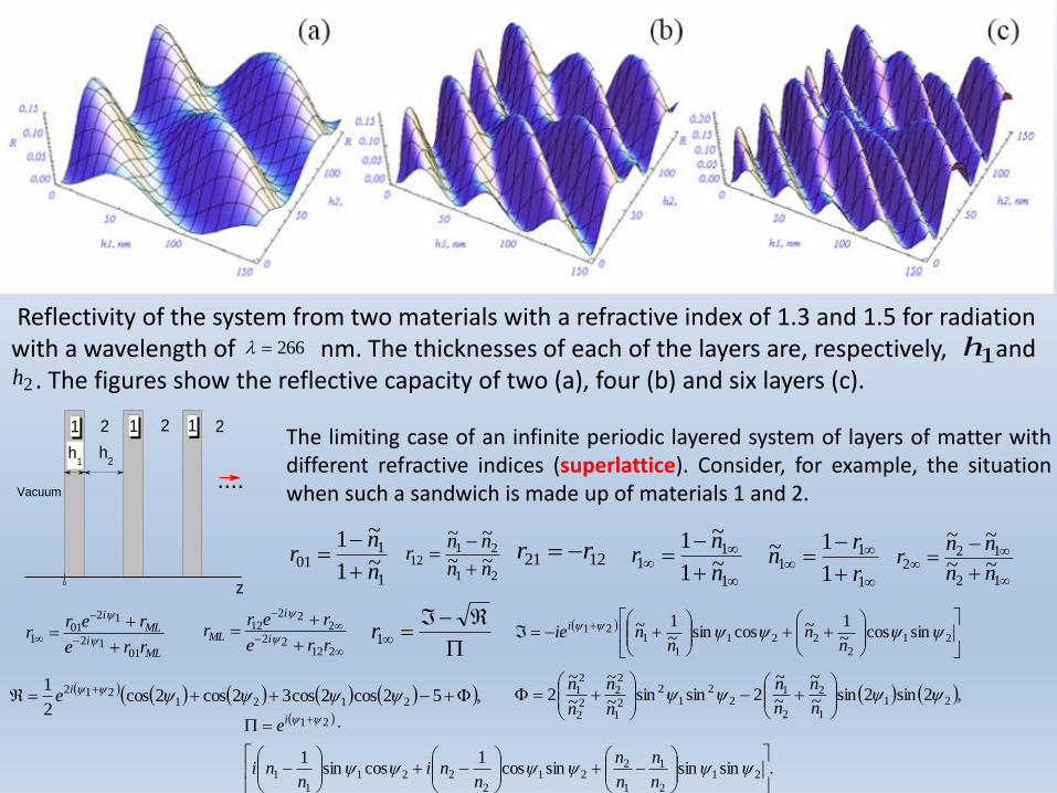
Reflectivity of the system from two materials with a refractive index of 1.3 and 1.5 for radiation with a wavelength of nm. The thicknesses of each of the layers are, respectively, and
. The figures show the reflective capacity of two (a), four (b) and six layers (c).
266 1h
2h
0
h2
22 11
Vacuum
1 2
....h
1
z
The limiting case of an infinite periodic layered system of layers of matter withdifferent refractive indices (superlattice). Consider, for example, the situationwhen such a sandwich is made up of materials 1 and 2.
1
101 ~1
~1
n
nr
21
2112 ~~
~~
nn
nnr
1221 rr
1
11 ~1
~1
n
nr
1
11
1
1~
r
rn
12
122 ~~
~~
nn
nnr
MLi
MLi
rre
rerr
0112
1201
1
21222
222
12
rre
rerr
i
i
ML
1r
21
2
221
1
121 sincos~
1~cossin~1~
nn
nnie
i
,52cos2cos32cos2cos2
12121
212
ie ,2sin2sin~
~
~
~2sinsin~
~
~
~2 21
1
2
2
12
21
2
21
22
22
21
n
n
n
n
n
n
n
n
.sinsinsincos1
cossin1
21
2
1
1
221
2
221
1
1
21
n
n
n
n
nni
nni
ei

0 50 100 1500.0
0.5
1.0
R
h2, nm
n1 = 1.3
n2 = 1.5
h1 = 50 nm
= 266 nm
Reflectivity of superlattice versus thickness of the second layer.Reflectivity tends to unity in some range of thickness.
A photonic crystal is a periodic optical nanostructure that affects
the motion of photons in much the same way that ionic lattices
affect electrons in solids. Photonic crystals occur in nature in the
form of structural coloration and animal reflectors, and, in
different forms, promise to be useful in a range of applications. In
1887 the English physicist Lord Rayleigh experimented with
periodic multi-layer dielectric stacks, showing they had a
photonic band-gap in one dimension. Research interest grew with
work in 1987 by Eli Yablonovitch and Sajeev John on periodic
optical structures with more than one dimension—now called
photonic crystals.
Photonic crystals can be fabricated for one, two, or three dimensions. Two-dimensional photonic-crystal
fibers are used in nonlinear devices and to guide exotic wavelengths. Three-dimensional crystals may one day
be used in optical computers. Three-dimensional photonic crystals could lead to more efficient photovoltaic
cells as a source of power for electronics, thus cutting down the need for an electrical input for power.
Photonic crystal
Floquet–Bloch theorem൯𝐸(𝑧 + 2𝑑) = 𝑒𝑖𝑘2𝑑𝐸(𝑧

0x
2
k2
k1
1
Media
1 M
edia
2
E
k
z
x
1
(a)
0
(b)
H
2
k2
z
k1
1
1
k
Media
1 M
edia
2
ТМ – wave, p-polarization ТE – wave, s-polarization
zzkyykxxkii ee
kr
i
iz
iy
ix kkkk 2
0
222
20
ck
sinsinsin2011010
kkk
1Reflection law Snell's law
2
1
sin
sin
,cos10 kkz
,cos101 kkz
,sincos 212020
2 kkkz
Incident wave
Reflected wave
Transmitted wave
21212
21212
0
1
sincos
sincos
H
Hrp
2121
2121
0
1
sincos
sincos
E
Ers
0 45 900.0
0.5
1.0
0 45 900.0
0.5
1.0
Rs,
Rp
, grad
(a)
1 = 1
2 = 1.5
2
B =
56.3
o
p
s
s p
r = 41.8
o
B =
33.7
o
1 = 1.5
2
2 = 1
(b)
Rs,
Rp
, grad
1212sin nnr
Brewster angle 1212 nntg B
Total internal reflection
Sir David Brewster
1781-1868

There is a layer of matter on the surfacewhich is optically different from thesubstrate substance. The thickness of thislayer is h. The incidence of radiation isinclined.
ppi
pip
prre
rer
H
Hr
23122
232
12
0
1
21212
21212
12
sincos
sincos
pr
2123
2132
2123
2132
23
sinsin
sinsin
pr
Frustrated Total Internal Reflection
ssi
sis
srre
rer
E
Er
23122
232
12
0
1
2121
2121
12
sincos
sincos
sr
213
212
213
212
23
sinsin
sinsin
pr
4.1:1:5.1:: 321 nnn
The ratio of the components of the Poynting vector in
the medium 3 to the component of the Poynting vector
in the incident wave in the medium 1 (a). A contour
graph of the same function (b). The geometry of the
radiation drop is shown in Figure, the case of s-
polarization is considered.
321 nnn 23 nn TIR FTIR
0 2 4 6 8 100.0
0.5
1.0
Sz/S
0
k0 h
n = 1.2
n = 1.5
n = 2
= 70o
FTIR between materials
with refractive indices n1
= n3 = n separated by a
vacuum. The angle of
incidence 70 degrees
exceeds the angle of total
internal reflection.

Heat equation
cvr¶T
¶t=Ñ k ÑT( )+Q
Heat diffusivity [cm2/s]
Q =a 1-R( ) I t( )e-az
T t = 0( ) =T¥ -k
¶T
¶zz=0
= 0
T z = 0( ) =T¥
+a
crI t - t
1( )0
t
ò ea2Dt
1 erfc a2Dt1dt
1
D =k
cr
Schrödinger equation
erf x( ) =2
pe-t2 dt
0
x
ò
erfc x( ) =1- erf x( ) =2
pe-t2 dt
x
¥
ò
Error function
Complimentary Error function

Energy balance
mc T -T¥( ) = SF Temperature rise depends on fluence
Which pulse shape with the same fluence yields the highest surface temperature?
Optimal laser heating
Ramanujan1887-1920
Kantorovich1912-1986
Pontryagin
1908-1988
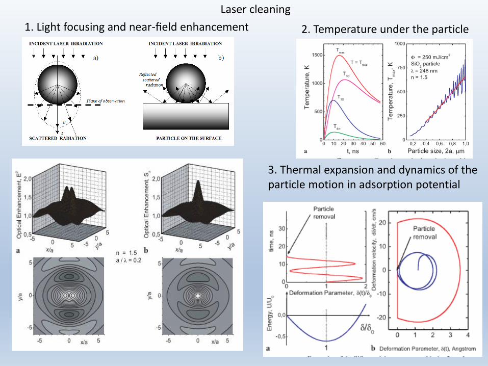
Laser cleaning
1. Light focusing and near-field enhancement 2. Temperature under the particle
3. Thermal expansion and dynamics of the particle motion in adsorption potential

ProblemsProblem 1. If the degree of monochromatic of the incident light is low, then the interferenceeffects caused by reflection from two faces of the plate does not occur, and addition ofintensities of light play the dominant role. Find the coefficient of plate transmission undersuch approximation.
I0 R
(1)
A(1)
T(1)
A(2)
A(3)
R(2)
T(2)
0
h
z
R
1-R
A(4)
1i
iR
1i
iTT
22
22
1
1
n
nRSolution. heRA 11
heRT 21 1
heRRA 22 1
h
hhhh
eR
eReRReRReRT
22
25243222
1
1...111
h
h
eR
eRR
22
2
1
211
0 500 1000 15000.0
0.5
1.0
1
2
Tra
nsm
ittivity,
T
h, nm
= 530 nm
n = 1.5
= 0.1

Problem 2. Find a maximum absorptivity of the thin film h<<1 with a high complex dielectricpermeability , .
nn
nr ~
21~1
~112
2
122
122
0
1 1
re
re
E
Er
i
i
Solution.
ih
hr
~
~
inn ~~ 1,1 n
ih
ihnd
~
~2
14
22222
22222
2
hn
hn
hn
rR
14
144
22222
22222
2
hn
hn
hhn
dT
TRA 1 Finding of maximum A yields h << h0 22
nh
1
For Cu and CO2 laser =10.6 m the optical constants are n= 12.8 and = 52.1. This yields h 1.17 nm approximately three atomic layers.
0 10 20 30 40 500.0
0.1
0.2
0.3
Absort
ptivity, A
h, nm
1
2
Cu
= 10.6 m
n = 12.8
= 52.1

Problem 3. Find an approximation for the absorptivity of weakly absorbing << n , and thin h << 1 dielectric film on the surfaces of high reflecting metal substrate A0 << 1. The film thickness h can be comparable with the radiation wavelength .
Solution. For a metal substrate with A0 << 1 and 1sn 1s
14
122
2130
ss
s
n
nrA
ss inr 2113
22
2
121
2
1
1
n
i
n
nr
With << 1 For h << 1 hii ehe 12
n4where . However h is not a small value.
2sin111
sin21
222
02
2
hhnhnnn
hhAnrhA
1hFor one can find
2
222
022
2
2
0 1414
11
hnAh
n
nAhA
2sin1
sin21
222
02
2
hnn
hhAnrhA
0 2 4 6 8 10 120.0
0.5
1.0
4
3
3
2
A
h, m
1
Cu + Cu2O
= 10.6 m

Problem 4. Optical discs (CD, DVD, Blue Ray) using the variation of the reflectivity of the thinmetal film between layers of transparent dielectric . Find the film thicknesswhich produces the highest contrast for the change of reflectivity. In optical recordingGeSbTe films the crystalline state approximately twice higher than in the amorphous state,e.g. for = 650 nm the crystalline material has n = 3.9 and = 3.6 while the amorphousmaterial has n = 3.9 and = 2.1 . Refractive index for dielectric is . Consider astrong absorption coefficient .
0,~ sss nn
Solution. where . After some algebra one can find
5.1sn
12 hez
23122
232
12
0
1
rre
rer
E
Er
i
i
nn
nnrr
s
s~
~
2312
23210
2
02
2cos2sin2
2cos21
zbhbhbzb
zhzarR
nnk 42 0 where and coefficients
2222220 4 ss nnnna 222
0 snnb 2221 4 ss nnnb
2222222 22 ssss nnnnnnb 222
3 snnb
1zFor
2cos22sin8
1 22222
222
2
hnnnnnhnn
nn
enRR sss
s
hs
m
22
22
s
sm
nn
nnRwhere
2222
2
02
2
ss
ss
nnnn
nnnnnhktg
The equation for the optimal thickness with highest reflectivity is
This yields h = 37.5 nm for crystalline and h = 38.4 forAmorphous film.

This yields h = 37.5 nm for crystalline and h = 38.4 nm for amorphous film. Solid line – exact solution, dashed line is approximation.
In reality for optical recording the opticalcontrast is important, i.e. the difference inreflectivity for different states. Typical contrastis about 15% and CST thickness h is about 80nm.

Problem 5. Find formulas for absorptivity versus incidence angle for good metal.
Solution. where and . After some algebra one can find 2 in 1n 1
1cos
1cos
pr
21 pp rA
221cos
cos4
n
nAp
Maximal absorptivity at whereB 2122cos
nB
nnnAp 12
2
max At IR range where n % 83122max pA
22cos
cos4
n
nAsFor s-polarization
one can see monotonous dependence

Literature
1. Landau, L. D., Bell, J. S., Kearsley, M. J., Pitaevskii, L. P., Lifshitz, E. M., Sykes, J. B., Electrodynamics of continuous media (Vol. 8). Elsevier, 2013.
2. Born, M. and Wolf, E., Principles of optics: electromagnetic theory of propagation, interference and diffraction of light. Elsevier, 2013
3. Mandelstam, L.I., 1971. Lectures on optics, relativity theory and quantum mechanics. Nauka Eds., Moscow, 1972. 440 pp.
4. Stratton, J.A., Electromagnetic theory. John Wiley & Sons, 2007.
5. Karlov, N.V., Kirichenko, N.A. and Luk'yanchuk, B.S., Laser thermochemistry. Cambridge International Science Pub., 2000.
6. Landau, L. D. & Lifshitz E. M., The Classical Theory of FieldsButterworts–Heinemann, London, 1973
7. I. L. Hooper, T. W. Preist, J. R. Sambles, Making Tunel Barriers (Including Metals) Transparent, Phys. Rev. Lett. 97, 053902 (2006)

Home work
1. Reproduce solutions of the Problems 1 – 5
2. Suggest a new problem and its solution