Embed Size (px)
Citation preview
HAL Id: hal-00919454https://hal.archives-ouvertes.fr/hal-00919454
Submitted on 16 Dec 2013
HAL is a multi-disciplinary open accessarchive for the deposit and dissemination of sci-entific research documents, whether they are pub-lished or not. The documents may come fromteaching and research institutions in France orabroad, or from public or private research centers.
L’archive ouverte pluridisciplinaire HAL, estdestinée au dépôt et à la diffusion de documentsscientifiques de niveau recherche, publiés ou non,émanant des établissements d’enseignement et derecherche français ou étrangers, des laboratoirespublics ou privés.
Borehole stability analysis in a thermoporoelasticdual-porosity medium
Rachel Gelet, Benjamin Loret, Nasser Khalili
To cite this version:Rachel Gelet, Benjamin Loret, Nasser Khalili. Borehole stability analysis in a thermoporoelasticdual-porosity medium. International Journal of Rock Mechanics and Mining Science & GeomechanicsAbstracts, Pergamon and Elsevier, 2012, 50, pp.65-76. hal-00919454
Borehole Stability Analysis in a Thermo-Poro-Elastic
Dual Porosity Medium
Rachel Geleta,b, Benjamin Loreta,∗, Nasser Khalilib
aLaboratoire Sols, Solides, Structures, B.P. 53X, 38041 Grenoble Cedex, FrancebSchool of Civil and Environmental Engineering, The University of New South Wales, Sydney 2052, Australia.
Abstract
The problem of diffusion and mass transfer in dual porous media is considered in a three-phase framework. The solid phase is assumed to contain two distinct cavities filled with fluid.The porous mixture is composed of two overlapping media: the porous blocks and the fissurenetwork. The fluid can transfer between the cavities due to fluid pressure difference. In addition,hydraulic and thermal diffusions take place through the mixture. A global understandingof mass transfer, diffusion and deformation is provided. The governing equations associatedwith these phenomena are presented for a mixture in thermal equilibrium. The finite elementapproximation of the governing equations is formulated and applied to the stability analysisof a vertical borehole. A parametric analysis is carried out to evaluate the influence of masstransfer on the pressure profiles of the fluids around the borehole. Permeable and a semi-permeable boundary conditions are compared to predict the potential for failure of the wellboreunder drained and partially undrained conditions.
Keywords: thermo-poro-elasticity, dual porosity, thermal equilibrium, diffusion dominatedflow, mass transfer, borehole stability
1. Introduction
The influence of thermal loading on the behavior of fractured poro-elastic media is relevantto various applications, such as enhanced heavy-oil recovery by steam or hot water injection,thermal and hydraulic stimulations of tight reservoirs, management of nuclear waste disposalin a clay buffer, and geothermal hot dry rock energy extraction. In all these applications, aborehole or a tunnel is required and the stability analysis forms a crucial part of the design [1].
Currently borehole stability analyses under thermal loading are scarce and focus mainly onreservoirs represented by saturated rocks with a single porosity [2, 3, 4, 5, 6, 7, 8, 9, 10, 11, 12].A key factor influencing wellbore stability is the change of pore pressure on the lining of thewellbore due to mud penetration [5, 6, 7]. Failure typically occurs when the pore pressurereduces the effective confining pressure below a threshold value [8, 9].
Closed form solutions for thermally induced fluid flow around a borehole in low permeabilitymedia, where heat transfer is dominated by conduction, have been presented by a number ofinvestigators [2, 3, 4, 6]. McTigue [2, 3] provided analytical results for the thermoelastic response
∗Principal corresponding author
Email addresses: [email protected] (Rachel Gelet), [email protected] (BenjaminLoret), [email protected] (Nasser Khalili)
Preprint submitted to Elsevier October 20, 2011
*Revised ManuscriptClick here to view linked References
of saturated porous rocks with a single porosity, highlighting the importance of the thermalto hydraulic diffusivity ratio and the competition between the heat and the fluid flows. Wangand Papamichos [4] examined the thermally induced pore fluid pressure around a pumping wellfor both cold and warm injection processes, underlying the importance of the thermal couplingto accurately estimate the induced fluid flow rate in low permeability media. Chen and Ewy[6] investigated the thermoporoelastic effect on wellbore stability and analyzed the collapsefailure index in the region near the wellbore. Notable contributions have also been made byAbousleiman and Ekbote [10], Wang and Dusseault [11] and Pao et al. [12] on the effects ofanisotropy, conductive versus convective heat flow, and multi-phase flow on borehole instability.
Based on Biot’s theory of mixture [13], thermo-hydro-mechanical models have been ex-tended to account for the dual porosity concept introduced by Barenblatt et al. [14]. However,the existing literature focuses on consolidation [15] or on the dominance of convection overconduction phenomena [16, 17]. Nair et al. [17, 18] presented results on the sensitivity ofthe thermoelastic response in dual porosity media to fracture spacing, but based on severalrestrictions. In particular, the deformation field in their dual porosity model was formulated byassigning each cavity system with its own effective stress, deformation and overall compliance,in contradiction of the principle of effective stress where a single stress entity is defined for theentire solid skeleton [19, 21, 22, 20]. Furthermore, in their approach, to define the effectivestress parameters, the deformation fields of pore and fracture systems are assumed to work inseries which may not be applicable in real rocks.
The paper presents a fully coupled finite element formulation for a thermo-poro-elastic dualporous medium under non-isothermal conditions. The fractured porous medium is describedas a porous mixture composed of two overlapping continua: the porous blocks and the fissurenetwork. The solid phase has a special role as it provides the matrix skeleton and enclosesthe fluid phases. The theoretical model of the three-phase mixture is built by postulatingconstitutive equations for the three phases and by enforcing the balances of mass, momentumand energy. A summary of the governing differential equations is provided in Section 2. Theformulation presented is specified for a local thermal equilibrium between the phases, saturatedsoils and for diffusion dominated fluxes [23, 16]. The weak form of the governing equations andthe time-integration procedure to solve the coupled equations through a finite element methodare detailed in Section 3. The primary variables are the displacements, the pore fluid pressure,the pressure of the fluid in the fissures and the temperature of the mixture. The resultingsystem of equations is used to address the failure potential of a vertical borehole subjectedto both pressure and temperature gradients (Section 4). Simulations of heavy-oil recoverythrough thermal stimulation demonstrate the influences of the dual porosity approach and ofthe boundary conditions on the borehole stability (Section 5). In addition to the stability issue,the study focuses on mass transfer between the pore matrix and the fissure network; and onthe contrast in diffusivity ratios between the two cavities.
Notation: Vector and matrix quantities are identified by boldface letters, for example σ isthe total stress. I is the identity matrix. tr , ∇(·) and div denote respectively the trace, thegradient and the divergence operators.
2. Governing equations
Within a dual porosity conceptual framework (Khalili and Valliappan [19] and Khalili andSelvadurai [16]), differential equations describing the deformation, hydraulic and heat flows, andmass transfer through deformable fissured porous media may be expressed as (the convention
2

of summation over the repeated mute index i is used),
µ∂2uj∂xi∂xi
+ (λ+ µ)∂2ui
∂xi∂xj− ξp
∂pp∂xj
− ξf∂pf∂xj
− cTc
∂T
∂xj+ Fj = 0
∂
∂xi
(kpµp
∂pp∂xi
)= app
∂pp∂t
+ apf∂pf∂t
+ ξp∂2ui∂t ∂xi
+ apT∂T
∂t+ Γ
∂
∂xi
(kfµf
∂pf∂xi
)= aff
∂pf∂t
+ apf∂pp∂t
+ ξf∂2ui∂t ∂xi
+ afT∂T
∂t− Γ
∂
∂xi
(Λ∂T
∂xi
)= T
(apT
∂pp∂t
+ afT∂pf∂t
+cTc
∂2ui∂t∂xi
)+ aTT
∂T
∂t
(1)
in which,
ξp = (cp − cs)/c, ξf = 1− cp/c
apf = −(ξf − nf )(cp − cs), app = np cH,p + (ξp − np) cs − apf
aff = nf cH,f + (ξf − nf ) cs − apf , apT = (np − ξp) cT − np cT,p
afT = (nf − ξf ) cT − nf cT,f , aTT = ρCp,
Γ = η (pp − pf ), η = α kp/µp,
α = 4n(n+ 2)/l2 with n = 1, 2, 3,
(2)
where u = (uj) is the displacement of the solid phase, pp is the pressure of the pore fluid,pf is the pressure of the fissure fluid and the temperature of the mixture, which is in thermalequilibrium, is denoted T . The subscripts s, p, f refer to the solid skeleton, the pore fluid andthe fissure fluid, respectively.
Equation (1)1 uses the Lame constants λ and µ of the drained solid, the body force vec-tor Fi, the compressibility of the mixture c, the compressibility of the porous blocks cp, thecompressibility of the solid grains cs, and the volumetric thermal expansion coefficient of thesolid phase cT . Equations (1)2,3 require for each fluid k = p, f the macroscopic porosity nk,the macroscopic intrinsic permeability kk, and the dynamic viscosity µk. The hydraulic com-pressibility cH,k and the thermal compressibility cT,k are defined in eqn (11) from the intrinsicdensity ρk of the fluid k. A linear mass transfer function Γ = η (pp − pf ) defining the exchangeof fluid between the porous blocks and the fissure network is adopted [14, 24]. η is the leakageparameter defined by Warren and Root [24] through the factor α as a function of the averagefissure spacing l and the number n of normal sets of fissures. While the linear transfer func-tion is easily amenable to computational implementation and consistent with a thermodynamicanalysis, leading to positive dissipation, it is also known to be inaccurate at early times. Thenon linear Vermeulen scheme has been adopted by Zimmerman et al. [32] in the analysis of frac-tured geothermal reservoirs where, at each point of the fracture continuum, a porous block ofspherical shape is attached: the fluid diffuses in the block and the net flow through its boundaryis viewed as a source/sink term for the fracture continuum. Lu and Connell [33] have devised aone-dimensional semi-analytical scheme that provides the time course of the transferred massin a gas reservoir. At early times, while the rate of mass transfer in their model tends to vanish,it tends to a constant for the linear transfer scheme and to infinity for the Vermeulen scheme.Correspondingly, the mass transferred depends linearly on time in the linear transfer scheme,but on the square root of time in the schemes of Vermeulen and Lu and Connell, albeit withdistinct scaling factors. A simple, accurate while computationally efficient, model of transferthat avoids delving with a convolution product, is yet to come.
3

Equation (1)4 involves the overall heat capacity at constant strain and fluid pressure Cp,the overall density ρ, and the overall thermal conductivity Λ.
Equations (1) are direct consequences of the field equations (balance of momentum for themixture, balance of mass for each fluid phase, balance of energy for the mixture),
−divσ = F, (3)
−divJk = nk1
ρk
dkρkdt
+1
V
dVk
dt− ρktr
ρk, k = p, f, (4)
−divq = Tds
dt, (5)
where σ is the total stress, F is the body force vector, Jk is the flux of the fluid k and q is theheat flux of the mixture. The term ρktr represents the mass supply to the cavity k by the othercavity.
The initial configuration, which is taken as a reference, represents a state in equilibrium inwhich stress, strain, pressures and temperature can be non-zero. Departure from this referencestate is denoted ∆(.). The shear behavior is accounted for by the shear modulus µ of the(drained) solid skeleton eqn (40). The fluid does not react to shear stresses. The associatedrelationship links the elastic strain ǫ
el to the effective stress σ′,
tr ǫel = ctrσ′
3, dev ǫel =
devσ′
2µ(6)
in which the deviatoric parts of the elastic strain and of the effective stress are denoted dev ǫel
and devσ′, respectively. The thermo-mechanical constitutive matrix relates the isotropic part ofthe total stress tr σ/3, the volume variations of the fluids ∆Vp/V and ∆Vf/V , and the entropyvariation of the solid ∆ss to the isotropic part of the total strain tr ǫ, the fluid pressures pp, pfand the temperature change ∆T = T − T 0 by,
−trσ/3
∆Vp/V
∆Vf/V
∆ss
=
−1/c ξp ξf cT /c
ξp app − np cH,p apf (np − ξp) cT
ξf apf aff − nf cH,f (nf − ξf ) cT
cT /c (np − ξp) cT (nf − ξf ) cT ρsCp,s/T
tr ǫ
pp
pf
∆T
(7)
in which ρs is the apparent density of the solid equal to nsρs, ss is the apparent entropy of thesolid per unit volume [kg/m/s2] and Cp,s is the intrinsic heat capacity of the solid, at constantstrain and fluid pressure [J/kg.K]. ξp and ξf are the effective stress parameters, which define thehydro-mechanical coupling and apf is the coupling term ensuring compatibility of deformationbetween the two pore systems [25]. The apparent entropy variation of the generic fluid k isexpressed separately as,
∆sk = −nk cT,k pk + ρkCp,k
T∆T, k = p, f . (8)
By summing the contributions of the three phases, the entropy variation for the mixture intro-duces the heat capacity of the porous medium ρCp = ρsCp,s + ρp Cp,p + ρf Cp,f ,
∆s =cTc
tr ǫ+ apT pp + afT pf +ρCp
T∆T. (9)
4
The density of the thermo-barotropic fluid k varies with its pressure and temperature,
1
ρk
dkρkdt
= cH,k
dkpkdt
− cT,kdkT
dt, k = p, f , (10)
in which the compressibility cH,k and the thermal expansion cT,k are defined as,
cH,k =1
ρk
dkρkdpk
∣∣∣∣Tk
, cT,k = − 1
ρk
dkρkdT
∣∣∣∣pk
, k = p, f . (11)
The diffusion constitutive relations are described by uncoupled Darcy’s law and Fourier’s law,
Jk = − kkµk
∇pk, k = p, f ; q = −Λ∇T, (12)
while the mass transfer uses Barenblatt’s quasi-steady relationship [14],
ρktr = (−1)α ρ0 η (pp − pf ) , (13)
in which η is the leakage parameter, which controls the mass transfer due to the fluid pressuredifference between the two cavities, and α = 1 for k = p, α = 2 for k = f .
This thermo-hydro-mechanical model derives from an effective stress concept, eqn (7)1,
trσ
3+ ξppp + ξfpf =
tr ǫ
c− cT
c∆T, (14)
and accounts for hydraulic fluxes within the two cavities, overall heat flux and fluid exchangesbetween the two cavities. This model neglects convective effects, the gravity force and thecoupled diffusive terms between the hydraulic fluxes and the heat flux. Additional informationon the parameters of the model can be found in previous works [19], [16] and [26].
3. Finite element formulation
A mixed finite element formulation is developed in which the primary unknowns are thedisplacements u, the pore pressure pp, the pressure of the fissure fluid pf and the temperatureof the porous medium T . To compact the finite element formulation, it is instrumental tointroduce the functions fp, ff and fT defined as,
fp = app pp + apf pf + apT T + ξp div u+ η (pp − pf ) ,
ff = afp pp + aff pf + afT T + ξf div u− η (pp − pf ) ,
fT = T apT pp + T afT pf + aTT T + TcTc
div u,
(15)
in which the super-imposed dot indicates a partial time derivative.
3.1. The semi-discrete equations
Multiplying the field equations by the virtual fields δu, δp and δT and integrating by partsover the body V provides the weak form of the problem,
−∫
V
∇(δu) : σ dV +
∫
V
δu · F dV = −∫
∂V
δu · σ · n dS,
−∫
V
∇(δp) · Jk dV +
∫
V
δp fk dV = −∫
∂V
δpJk · n dS, for k = p, f ;
−∫
V
∇(δT ) · q dV +
∫
V
δT fT dV = −∫
∂V
δT q · n dS,
(16)
5

where n is the unit outward normal to the boundary ∂V . A generalized Galerkin procedure isadopted and the same interpolation functions are used for the primary unknowns and for thevariations. The primary unknowns are interpolated, within the generic element e, in terms ofnodal values through the interpolation functions Nu, Np, NT, respectively,
u = Nu ue; pk = Np p
ek, for k = p, f ; T = NTTe. (17)
The surface loading contributions of a generic element e are gathered into the vector Fsurfe and
the internal thermo-poro-elastic contributions into the vector Finte . The element contributions
to the force vectors (16) are equal to Finte − F
surfe ,
∫
V e
(Bu)Tσ − (Nu)
TF dV e
∫
V e
(∇Np)T Jp − (Np)
T fp dV e
∫
V e
(∇Np)T Jf − (Np)
T ff dV e
∫
V e
(∇NT)T q− (NT)
T fT dV e
−
∫
∂V e
(Nu)Tσ · n dSe
∫
∂V e
(Np)T Jp · n dSe
∫
∂V e
(Np)T Jf · n dSe
∫
∂V e
(NT)T q · n dSe
, (18)
where Bu is the standard strain-displacement matrix, namely ǫ = Buue. Inserting the total
stress (7)1 and the hydraulic and thermal fluxes (12) in (18) yields a non-linear system ofequations including- an element contribution to the balance of momentum of the mixture,
Eeuu u
e −Ceup (ξp p
ep + ξf p
ef ) − cT
cCe
uTTe −Reu, (19)
- an element contribution to the balance of mass of the pore fluid,
−[Jekp
+ ηMepp]pp
e + ηMepp pf
e
−Mepp(app p
ep + apf p
ef )−Me
pT apT Te − ξpCepu u
e −Repp
,(20)
- an element contribution to the balance of mass of the fissure fluid,
−[Jekf
+ ηMepp]p
ef + ηMe
pp pep
−Mepp(aff p
ef + apf p
ep)−Me
pT afT Te − ξf Cepu u
e −Repf,
(21)
- an element contribution to the balance of energy of the mixture,
−QeΛTe −MeT
pT T (apT pep + afT pe
f )− aTT MeTT Te − T
cTc
CeTu u
e −ReT. (22)
Details of the element force vectors and matrices are provided in Appendix A. The contributionof the element e to the global set of equations may be cast in a matrix format,
KeXe + D
e
(dXe
dt
)− F
e . (23)
6
Here Ke is the element stiffness matrix and D
e the element diffusion matrix,
Ke =
Keuu Ke
uppKe
upfKe
uT
0 Kepp pp
Kepp pf
0
0 Kepf pp
Kepf pf
0
0 0 0 KeTT
, D
e =
0 0 0 0
Depp u De
pp ppDe
pp pfDe
pp T
Depf u
Depf pp
Depf pf
Depf T
DeTu De
TppDe
TpfDe
TT
; (24)
while Fe is the element load vector, and X
e the element unknown vector,
Fe =
[Re
u Repp
Repf
ReT
]T, X
e =[ue pe
p pef Te
]T. (25)
All sub-matrices of Ke and D
e are listed in Appendix B. The resulting global non-linearsemi-discrete equations (18) for the unknown vector X imply the residual R to vanish,
R = Fsurf (S,X)− F
int
(X,
dX
dt
)= 0, (26)
in which Fint is the vector of internal forces and F
surf is the vector of surface loadings denotedcollectively by S.
3.2. Time integration
The semi-discrete equations are integrated through a generalized trapezoidal rule definedby a scalar α ∈ ]0, 1]. At step n+ 1, the equations are enforced at time tn+α = tn + α∆t, with∆t = tn+1 − tn, namely
Rn+α = Fsurf (Sn+α,Xn+α)− F
int (Xn+α,Vn+α) = 0. (27)
In the above relation, we define Z = S,X,V as,
Zn+α = (1− α)Zn + αZn+1, (28)
and Xn+1 and Vn+1 are approximations of X(tn+1) and (dX/dt)(tn+1) respectively. The system(27) is solved iteratively by an explicit/implicit operator splitting, namely at iteration i+ 1,
Ri+1n+α = F
surfE (Sn+α,X
in+α)− F
intI (Xi+1
n+α,Vi+1n+α) = 0, (29)
in which,
i = 0 :
X0n+1 = Xn + (1− α)∆tVn
V0n+1 = Vn
for i ≥ 0 :
Xi+1n+1 = Xn +∆t V i+1
n+α = X0n+1 + α∆t V i+1
n+1 = Xin+1 + α∆t∆V
Vi+1n+1 = V
in+1 +∆V
(30)
where Xin+1 is defined as the predictor value by,
i ≥ 0 : Xin+1 = X
0n+1 + α∆tVi
n+1 (= Xin+1 for i > 0). (31)
and,
Xi(+1)n+α = (1− α)Xn + αX
i(+1)n+1 , V
i+1n+α = (1− α)Vn + αVi+1
n+1. (32)
7
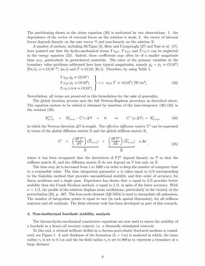
The partitioning shown in the above equation (29) is motivated by two observations: 1. thedependence of the vector of external forces on the solution is weak; 2. the vector of internalforces depends linearly on the rate vector V and non-linearly on the solution X.
A number of authors, including McTigue [3], Bear and Corapcioglu [27] and Nair et al. [17],have pointed out that the hydro-mechanical terms T apT , T afT and T cT /c can be neglectedin the energy equation (22). Indeed, these coefficients may often be of a smaller magnitudethan aTT , particularly in geotechnical materials. The rates of the primary variables in theboundary value problems addressed here have typical magnitudes, namely pp = pf ≈ O(104)[Pa/s], u ≈ O(10−6) [m/s] and T ≈ O(10) [K/s]. Therefore, by using Table 1,
T apT pp ≈ O(101)
T afT pf ≈ O(100)
T cT /c tr ǫ ≈ O(101)
<< aTT T ≈ O(105) [W/m3]. (33)
Nevertheless, all terms are preserved in this formulation for the sake of generality.The global iteration process uses the full Newton-Raphson procedure as described above.
The equation system to be solved is obtained by insertion of the time-integrator (30)-(32) inthe residual (29),
Ri+1n+α = R
in+α − C
∗α∆V = 0 ⇔ C∗ (α∆V) = R
in+α, (34)
in which the Newton direction ∆V is sought. The effective diffusion matrix C∗ can be expressed
in terms of the global diffusion matrix D and the global stiffness matrix K,
C∗ =
(∂F int
I
∂V
)(Xi
n+α)
︸ ︷︷ ︸D
+
(∂F int
I
∂X
)(Xi
n+α)
︸ ︷︷ ︸K
α∆t, (35)
where it has been recognized that the derivatives of FintI depend linearly on V so that the
stiffness matrix K, and the diffusion matrix D do not depend on V but only on X.The time step ∆t is increased from 1 to 1000 s in order to keep the number of computer time
to a reasonable value. The time integration parameter α is taken equal to 2/3 correspondingto the Galerkin method that provides unconditional stability and first order of accuracy, forlinear problems and a single pass. Experience has shown that α equal to 2/3 provides betterstability than the Crank-Nicolson method, α equal to 1/2, in spite of the lower accuracy. Withα = 1/2, the profile of the solution displays some oscillations, particularly in the vicinity of theperturbation [28], p. 467. The four-node element (QUAD4) is used to interpolate all unknowns.The number of integration points is equal to two (in each spatial dimension), for all stiffnessmatrices and all residuals. The finite element code has been developed as part of this research.
4. Non-isothermal borehole stability analysis
The thermo-hydro-mechanical constitutive equations are now used to assess the stability ofa borehole in a heavy-oil recovery context, i.e. a thermally stimulated reservoir.
To this end, a vertical wellbore drilled in a thermo-poro-elastic fractured medium is consid-ered, see Figure 1. A unit thickness of the formation (h = 1m) is analyzed in which, the innerradius r1 is set to 0.1m and the far-field radius r2 is set to 800m to represent a boundary at alarge distance.
8

We denote the initial (prior to drilling) pore and fissure pressures as p0p and p0f ; and the
initial temperature as T 0. The fully saturated formation is located at a depth of 1000m and issubjected to the following vertical gradients of in situ stresses, fluid pressures and temperature,
∂σ0z/∂z = −29.0 kPa/m,
∂σ0x/∂z = ∂σ0
y/∂z = −23.5 kPa/m,
∂p0p/∂z = ∂p0f/∂z = 9.8 kPa/m,
∂T 0/∂z = 0.05 C/m.
(36)
The fractured reservoir is idealized as a dual porosity medium with the isotropic materialproperties presented in Table 1. Since both the loading conditions display symmetry about thevertical axis of the wellbore an axi-symmetric formulation is employed. To reduce computationaltime without loss of accuracy, a graded mesh is used and the size of the finite elements isincreased along the radial direction (towards r2 in Figure 1) according to a logarithmic rule.
x-y plane
r-z plane
x, r
y
z
θz
0σ
y
0σ
x
0σ
r
z
r r1 2
h
0
Refined zone
Figure 1: Schematic diagram of a vertical borehole subjected to in situ stresses (left). 2D representation of theproblem with an axi-symmetric mesh in the r-z plane (right).
The cap rock on the top of the reservoir is considered to be rigid, constraining the verticaldeformation of the reservoir. The initial vertical strain, which represents the deformationexperienced by the reservoir prior to drilling,
ǫ0z = − ν
E
(σ0x + σ0
y
)+
1
Eσ0z +
cp − cs3
p0p +c− cp
3p0f +
cT3(T 0 − T 0)
︸ ︷︷ ︸= 0
, (37)
is obtained from equation (7).
4.1. Boundary conditions
The boundary conditions at the far-field radius r = r2, at the top z = h and at the bottomz = 0 of the dual porous medium are presented in Table 2. To test the stability of the borehole,a constant mud pressure pw = 12.0MPa is applied. The boundary conditions on the wellboreradius r = r1 are handled separately according to two distinct configurations.
Indeed, two types of conditions are envisaged at the dual-porosity wellbore wall r = r1: afully permeable boundary condition on both cavities and a semi-permeable boundary conditionin which the porous blocks are sealed by the drilling mud cake and have zero outward flux.
9

Material parameter Value Unit Ref.
Elastic modulus E 9.5 GPa 1Poisson’s ratio ν 0.25 - 1Bulk modulus of grains Ks = 1/cs 10 GPa 1Bulk moduli of the fluids Kk = 1/cH,k 4.3 GPa 1Viscosities of the fluids µp = µf 10−3 Pa.s 1,2
Porous blocks porosity np 0.15 - 1,2Porous blocks permeability kp 5× 10⁻²⁰ m2 1,2Compressibility ratio cp/c 0.9 - 3
Fissure network porosity nf 0.1 × np - 3Fissure network permeability kf 10 × kp m2 3Thermal conductivity of the porous medium λ 2.65 W/m.K 1Volumetric thermal expansion of the porous medium cT 1.8×10⁻⁵ 1/K 1,2Volumetric thermal expansion of the fluids cT,p = cT,f 4.5×10⁻⁴ 1/K 4Heat capacity of the porous medium Cv 837 J/kg.K 1,2Density of the porous medium ρ 1980 kg/m3 1,2
Table 1: Input parameters representative of a homogeneous isotropic dual porous medium. 1: Nair et al. [18],2: Nair et al. [17] Gulf of Mexico Shale, 3: Wilson and Aifantis [29] and 4: Kestin [30] p. 541.
r = r2 r ∈]r1, r2[z ∈ [0, h] z = h and z = 0
σr(r2, z) = σ0r ǫz(r, z) = ǫ0z
pp(r2, z) = p0p Jp(r, z) = 0
pf (r2, z) = p0f Jf (r, z) = 0
T (r2, z) = T 0 q(r, z) = 0
Table 2: Boundary conditions for a thermal recovery test with an axi-symmetric mesh in the r-z plane.
a) Permeable boundary. The radial stress, the pressures of the fluid in the two cavities and thetemperature are considered to be totally controlled at the wellbore, for any z ∈ [0, h],
σr(r1, z) = σ0r H(−t)− pw H(t),
pp(r1, z) = p0pH(−t) + pw H(t),
pf (r1, z) = p0f H(−t) + pw H(t), (38)
T (r1, z) = T 0 H(−t) + Tw H(t),
where H(t) is the Heaviside step function (Figure 2).b) Semi-permeable boundary. In this case a mud cake is formed on the borehole wall as thedrilling mud infiltrates into the permeable medium. Therefore, a pore matrix endowed withlow permeability can be sealed at the inlet by the mud cake. We term this boundary conditiona semi-permeable boundary, since the sealing process is applied only to the porous blocks(Figure 2). The second relationship in (38) is therefore changed to,
Jp(r1, z) = 0. (39)
10

Mud cake
sealing the
pore matrix
Zero Hydraulic flux
Borehole axis
Mud pressure
applied through
the fissure
H (t)
t0
t0
H (-t)p0pp0f ,
Zero Hydraulic flux
Figure 2: Sketch of a semi-permeable hydraulic boundary condition with zero flux at the porous blocks boundary.
The overall compressibility of the mixture c and the Lame constants of the drained solidλ and µ, are deduced from the Young’s modulus E and Poisson’s ratio ν through the elasticrelationships,
c = 31− 2ν
E, λ =
E ν
(1 + ν)(1− 2ν), µ =
E
2 (1 + ν). (40)
4.2. Characteristic parameters
In a porous medium with a single porosity, the pressure response to a heating/cooling testis controlled by the diffusivity ratio R =
√αH/αT of the hydraulic diffusivity αH over the
thermal diffusivity αT defined by McTigue [3],
αT =Λ
ρCv, αH =
kpµp
2µ(1− ν)
1− 2ν
B2(1 + νu)2(1− 2ν)
9(1 − νu)(νu − ν), (41)
in which B is the Skempton coefficient and νu is the undrained Poisson’s ratio,
1
B= 1 + np
cH,p − csc− cs
, νu =3 ν +B(1− 2ν)(1 − cs/c)
3−B(1− 2ν)(1− cs/c). (42)
In a dual porosity medium (2P), hydraulic diffusion takes place in two spatially separatedcavities, and as such two distinct diffusivity ratios can be defined. For the porous blocks, R istypically smaller than one, R < 1 with the thermal diffusion being faster than the hydraulicdiffusion. Conversely, for the fissure network R is greater than one, R > 1 in which the hydraulicflow is faster than the heat flow. Crucial to the understanding of the behavior is the fact thatthe porous blocks and the fissure network are endowed with opposite characteristics of diffusiondominance.
For the sake of comparison, the diffusivity ratio of the associated single porous medium(A1P) is also analyzed (Table 3). For this case, the overall porosity is defined as nA1P = np+nf
and the overall permeability as kA1P = kp + kf . This single porous medium is endowed witha single unknown pressure For this single porous medium (A1P), the thermal diffusivity frontis behind the hydraulic diffusion front with RA1P = 2.16, analogous to the fissure networkcharacteristic.
In addition to the diffusivity ratios, the responses of the dual porosity mixture are scrutinizedwith the help of two other characteristic parameters, namely, a characteristic time t∗ and acharacteristic leakage parameter η∗. Both parameters are defined with respect to a point ofinterest rc ∈]r1, r2[ in the vicinity of the borehole. This point, which defines the boundary ofthe failure zone, is chosen as equal to ten times the radius of the borehole, rc = 1m.
11

Parameter Pore matrix (2P) (A1P) Fissure network (2P)
Porosity, nk (-) 0.14 0.154 0.014
Permeability, kk (m2) 5 ×10⁻²⁰ 5.5 ×10⁻¹⁹ 5 ×10⁻¹⁹
Hydraulic diffusivity, αH (m2/s) 6.97 ×10⁻⁷ 7.48 ×10⁻⁶ 9.06 ×10⁻⁶
Thermal diffusivity, αT (m2/s) 1.6 ×10⁻⁶ 1.6 ×10⁻⁶ 1.6 ×10⁻⁶
Diffusivity ratio, R (-) 0.66 < 1 < 2.16 < 2.38
Table 3: Comparison between the diffusivity ratios R =√
αH/αT of the porous blocks, of the fissure networkas parts of dual porosity medium, and of the associated single porosity medium. Note that thermal diffusion isfaster than hydraulic diffusion for the pore matrix (2P) while the opposite holds for the fissure network (2P) andfoe the associated single porosity analysis (A1P).
A characteristic time defined as t∗ = (rc − r1)2/α represents the time that is required for
a diffusion front to reach the point of interest rc in which α is a diffusion parameter. For aregion of length rc − r1, the diffusion time scale distinguishes the early time from the late timeresponses of the system. The analysis of thermo-hydro-mechanical loading in dual porous mediahighlights three characteristic times, namely, the end of hydraulic diffusion through the fissuresat time 8.17 × 10⁴ s, second the end of thermal diffusion in the mixture at time 5.07 × 10⁵ s,and last the end of hydraulic diffusion through the pores at time 1.4 × 10⁶ s. We chose thecharacteristic time of the system to be the largest of these three characteristic times; therefore,at t = t∗, all the diffusion fronts should have reached rc.
The dimensionless characteristic leakage parameter η∗ is expressed as in [26],
η∗ = ηµp r
2c
kp + kf, (43)
in which µp = µf due to thermal equilibrium. For an average fracture spacing l equal to0.03 m, one set of fractures n = 1 and the material parameters presented in Table 1, theaverage characteristic leakage parameter is, according to eqn (43), equal to η∗av = 1.1× 10³.
5. Thermal effects on dual porous media
Numerical results of thermal effects in the vicinity of the borehole in a fractured reservoirare now presented (Table 1). Two sensitivity analyses are carried out: the influences of thetemperature loading ∆T = Tw − T 0 and of the leakage parameter η on the pressure and stressresponses of the system are examined. The variation with time of the effective stresses aroundthe borehole are scrutinized and a stability analysis is conducted at the most unfavorable time.
Results are presented from Figures 3 to 10. A continuum mechanics convention is used withcompressive stresses taken as negative.
5.1. Influence of temperature
The effect of thermal loading on a single porosity model has been analyzed by McTigue [3]who provides analytical responses to a half-plane subjected either to a jump of heat flux or toa jump of temperature. These analytical responses have been used to examine the response ofthe finite element code in the particular case of a single porosity model.
In what follows, the effect of temperature on a fractured medium is presented and thefeatures of the dual porosity approach are compared with a standard single porosity model.
12
Both heating and cooling tests are performed. The difference between the temperature of thefluid at the wellbore Tw and the temperature of the in situ fluid T 0 is successively set to +50 C,-50 C and 0 C. The leakage parameter is set equal to the average leakage parameter η∗ = η∗av .The results are presented at time t = 80 s, which corresponds to an early time response of thesystem and where the difference between the three loadings is the largest.
1 1.1 1.2 1.3 1.4 1.5−5
0
5
10
15
20
25
Radial distance : r/r1
Por
epre
ssure
s(M
Pa)
∆T = 50 oC
∆T = -50 oC
∆T = 0 oC
2PA1P
1 1.2 1.4 1.6 1.8 2
6
8
10
12
14
16
18
Radial distance : r/r1
Fis
sure
pre
ssure
s(M
Pa)
∆T = 50 oC
∆T = -50 oC
∆T = 0 oC
2PA1P
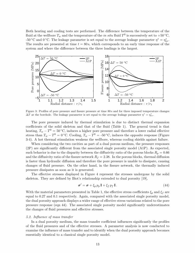
Figure 3: Profiles of pore pressure and fissure pressure at time 80 s and for three imposed temperature changes∆T at the borehole. The leakage parameter is set equal to the average leakage parameter η∗ = η∗
av.
The pore pressure induced by thermal stimulation is due to distinct thermal expansioncoefficients of the solid skeleton and that of the fluid (Table 1). The general trend is thatheating, Tw − T 0 = 50 C, induces a higher pore pressure and therefore a lower radial effectivestress than Tw − T 0 = 0 C. Cooling, Tw − T 0 = -50 C, induces the opposite response (Figure3-4). A hot thermal stimulation weakens the wellbore, whereas cooling shields against failure.
When considering the two cavities as part of a dual porous medium, the pressure responses(2P) are significantly different from the associated single porosity model (A1P). As expected,such behavior is due to the disparity between the diffusivity ratio of the porous blocks Rp = 0.66and the diffusivity ratio of the fissure network Rf = 2.38. In the porous blocks, thermal diffusionis faster than hydraulic diffusion and therefore the pore pressure is unable to dissipate, causingchanges of fluid pressure. On the other hand, in the fissure network, the thermally inducedpressure dissipates as soon as it is generated.
The effective stresses displayed in Figure 4 represent the stresses undergone by the solidskeleton. They are defined by Biot’s relationship extended to dual porosity [19],
σ′ = σ + ξp pp I+ ξf pf I . (44)
With the material parameters presented in Table 1, the effective stress coefficients ξp and ξf areequal to 0.27 and 0.1 respectively. Again, compared with the associated single porosity model,the dual porosity approach displays a wider range of effective stress variations related to the porepressure response (eqn 44). The associated single porosity model significantly underestimatesthe changes of fluid pressures and effective stresses.
5.2. Influence of mass transfer
In a dual porosity medium, the mass transfer coefficient influences significantly the profilesof the fluid pressures and of the effective stresses. A parameter analysis is now conducted toexamine the influence of mass transfer and to identify when the dual porosity approach becomesessentially identical to a classical single porosity model.
13

1 1.1 1.2 1.3 1.4 1.5
5
10
15
Radial distance : r/r1
−σ
, rr
(MPa)
∆T = -50 oC
∆T = 50 oC
∆T = 0 oC
2PA1P
1 1.1 1.2 1.3 1.4 1.520
25
30
35
Radial distance : r/r1
−σ
, θθ
(MPa)
∆T = -50 oC
∆T = 50 oC
∆T = 0 oC
2PA1P
Figure 4: Same as Figure 3. Profiles of radial effective stress and tangential effective stress, at time 80 s and forthree imposed temperature changes ∆T at the borehole.
The characteristic leakage parameter η∗eq corresponds to the minimum dimensionless masstransfer coefficient that delivers instantaneous hydraulic equilibrium at a time of interest. Fort = 80 s, η∗eq is equal to 1.1× 10⁶. This value was found by trial and error and is specific to thedual porous medium characterized in Table 1. Note that η∗eq is a time-dependent parameter.
The influence of mass transfer is illustrated by selecting three representative values of theleakage parameter: η∗/η∗eq = 0 which represents no mass transfer, η∗/η∗eq = 0.001 which repre-sents a low mass transfer, and η∗/η∗eq ≥ 1 which corresponds to instantaneous hydraulic equilib-rium. The leakage parameter is related to the average fissure spacing and to the porous blockspermeability, and hence represents the ability of the dual porous medium to transfer fluid massfrom one cavity to the other. In this section and hereafter, only heating tests ∆T = + 50 Cwill be considered.
The sensitivity of the fluid pressures to the leakage parameter is presented in Figure 5 for twodistinct types of boundary condition: (left) permeable boundary and (right) a semi-permeableboundary. A comparison with an associated single porous medium is also presented.
In general, the pore pressure increases due to a combination of low permeability and higherthermal expansion for the fluid than for the solid, whereas the fissure pressure dissipates rapidlydue to a higher permeability. For η∗/η∗eq = 0, the two fluid fields are de-coupled and no masstransfer occurs. For η∗/η∗eq = 0.001, moderate mass transfer takes place as the pore pressuredissipates into the fissures. Consequently, the pore pressure peak in the porous blocks is lowerthan for η∗/η∗eq = 0, and the pressure in the fissure network is higher than the associated singleporosity response. Finally, for η∗/η∗eq ≥ 1, the mass transfer between the pores and the fissuresis instantaneous and the two cavities are in hydraulic equilibrium. Note that this equilibriumpressure is not equal to the fissure pressure when η∗/η∗eq = 0, but is equal to the pressureresponse of the associated single porous medium. For η∗/η∗eq ≥ 1, the pore pressure, the fissurepressure and the pore pressure of the associated single porosity model superpose.
For a permeable boundary, the pore pressure maximum is located a short distance from thewellbore wall due to a flux inward to the formation Jp ≥ 0 for radii larger than r/r1 ≥ 1.2 anda flux outward to the wellbore Jp ≤ 0 for radii smaller than r/r1 ≤ 1.1. For a semi-permeableboundary, the maximum is located at the borehole itself due to the flux of the porous blocksJp = 0, which induces a zero pore pressure gradient ∇pp = 0 at r = r1. In addition, themagnitude of the pore pressure maximum is higher for the semi-permeable boundary than forthe permeable boundary since the pore fluid can only dissipate internally and through mass
14

transfer. The pore pressure peak is smaller for the permeable boundary due to the directdissipation the pressure through the wellbore wall.
Permeable boundary Semi-permeable boundary
1 1.1 1.2 1.3 1.4 1.5
12
16
20
24
28
Radial distance : r/r1
Flu
idpre
ssure
s(M
Pa)
η∗/η∗eq = 0
η∗/η∗eq = 0
η∗/η∗eq = 0.001
η∗/η∗eq ≥ 1
Pore fluidFissure fluidA1P
1 1.1 1.2 1.3 1.4 1.510
15
20
25
30
35
40
Radial distance : r/r1
Flu
idpre
ssure
s(M
Pa)
η∗/η∗eq = 0
η∗/η∗eq = 0
η∗/η∗eq = 0.001
η∗/η∗eq ≥ 1
Pore fluidFissure fluidA1P
Figure 5: Profiles of pore pressure and fissure pressure, at time 80 s, for a thermal loading equal to Tw−T 0 = 50 C.
1 1.2 1.4 1.6 1.8 2
6
8
10
12
14
16
18
Radial distance : r/r1
−σ
, rr
(MPa)
η∗/η∗eq = 0
η∗/η∗eq = 0.001
η∗/η∗eq ≥ 1
A1P
1 1.2 1.4 1.6 1.8 220
25
30
35
Radial distance : r/r1
−σ
, θθ
(MPa)
η∗/η∗eq = 0
η∗/η∗eq = 0.001
η∗/η∗eq ≥ 1
A1P
Figure 6: Profiles of effective radial stress and effective tangential stress, at time 80 s, accounting for a permeable
boundary, for a thermal loading equal to Tw − T 0 = 50 C.
The sensitivity of the effective stresses to the mass transfer coefficient is illustrated in Figures6 and 7. The compressive effective radial stress experiences a significant drop for η∗/η∗eq = 0,which tends to diminish for high mass transfer η∗/η∗eq ≥ 1. By comparing Figures 6 and 7, thesemi-permeable boundary is seen to introduce a greater reduction in effective radial stress thanthe permeable boundary. For a low leakage parameter (close to zero), the effective radial stressshifts from compressive to tensile. The positive effect of the compressive mud pressure appliedat the borehole is annihilated by the thermally induced increase in pore fluid pressure.
Mass transfer from the porous blocks to the fissure network increases the dissipation ofthe pore pressure and conversely decreases the dissipation of the fissure pressure. This in turnincreases the apparent diffusivity ratio of the pore matrix and decreases the apparent diffusivityratio of the fissure network. For the intermediate leakage parameters η∗/η∗eq ≤ 0.1, the dualporosity approach is the only one which can represent correctly the reduction in the effectiveradial stress induced by the pore pressure response.
15

1 1.2 1.4 1.6 1.8 2−2
2
6
10
14
18
Radial distance : r/r1
−σ
, rr
(MPa)
η∗/η∗eq = 0
η∗/η∗eq = 0.001
η∗/η∗eq ≥ 1
A1P
1 1.2 1.4 1.6 1.8 220
25
30
35
Radial distance : r/r1
−σ
, θθ
(MPa)
η∗/η∗eq = 0
η∗/η∗eq = 0.001
η∗/η∗eq ≥ 1
A1P
Figure 7: Same as Figure 6 for a semi-permeable boundary.
5.3. Time profiles
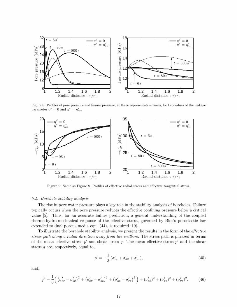
The variation with time of the fluid pressures gives an indication of the time scale at whichthe dual porosity model has the largest influence on the effective stress response. The pressureand stress profiles are shown for three representative times, namely at the very short time t = 6 scorresponding to t/t∗ = 4.2 10−6, at the short time t = 80 s corresponding to t/t∗ = 5.5 10−5
and finally at the intermediate time t = 800 s corresponding to t/t∗ = 5.5 10−4. Because thecharacteristic time t∗ is related to the slowest diffusion phenomenon (and does not account formass transfer effects), the ratio t/t∗ remains small even for the intermediate time. Focusing ona permeable boundary at the wellbore and on a heating test Tw − T 0 = 50 C, the results arepresented for two values of the dimensionless leakage parameter representing an infinite fracturespacing, η∗ = 0, and an average fracture spacing equal to 0.03m, η∗ = η∗av.
Over time, the pore pressure front propagates into the formation away from the boreholewith a diminishing pressure peak (Figure 8). As expected, the larger the leakage parameter, thefaster the dissipation of the pore pressure. Contrary to the pore pressure behavior, the pressurein the fissure network dissipates more slowly with an increase in the leakage parameter. Notethat for the very short time response (t = 6 s), average mass transfer does not play a significantrole in the fluid pressure response of the system and pore and fissure fluid pressures, for η∗ = 0and η∗ = η∗av, differ little.
As time elapses, the effective radial stress becomes more compressive as a consequenceof diffusion (Figure 9). At the time t = 6 s, the effective radial stress displays the highestcompressive reduction due to the slow dissipation of the pore pressure. Similarly, there is anuneven reduction in the compressive effective tangential stress at very short time. For botheffective stresses at t = 6 s and t = 800 s, the two curves η∗ = 0 and η∗ = η∗av are superposed.Over time, the effective tangential stress becomes less compressive while the effective radialstress behaves conversely. The time required for the effective stresses to attain steady state isdirectly related to the mass transfer coefficient.
At t = 6 s, mass transfer and dissipation have not taken place yet. At the intermediate timet = 800 s, hydraulic equilibrium has almost been reached for the average mass transfer valueη∗ = η∗av ; however, the influence of the diffusion and the mass transfer in the form of a differencein pore and fissure pressures is still prominent at t = 80 s. The reduction in compressive radialeffective stress is maximum at t = 6 s, and hence the borehole failure analysis is most criticalat the very short time scale.
16
1 1.2 1.4 1.6 1.8 28
12
16
20
24
28
32
Radial distance : r/r1
Por
epre
ssure
(MPa)
t = 6 s
t = 80 st = 800 s
η∗ = 0η∗ = η∗av
1 1.2 1.4 1.6 1.8 28
10
12
14
16
18
Radial distance : r/r1
Fis
sure
pre
ssure
(MPa)
t = 6 s
t = 80 s
t = 800 s
η∗ = 0η∗ = η∗av
Figure 8: Profiles of pore pressure and fissure pressure, at three representative times, for two values of the leakageparameter η∗ = 0 and η∗ = η∗
av .
1 1.2 1.4 1.6 1.8 20
5
10
15
20
Radial distance : r/r1
−σ
, rr
(MPa)
t = 6 s
t = 80 s
t = 800 s
η∗ = 0η∗ = η∗av
1 1.2 1.4 1.6 1.8 220
25
30
35
Radial distance : r/r1
−σ
, θθ
(MPa)
t = 6 s
t = 80 s
t = 800 s
η∗ = 0η∗ = η∗av
Figure 9: Same as Figure 8. Profiles of effective radial stress and effective tangential stress.
5.4. Borehole stability analysis
The rise in pore water pressure plays a key role in the stability analysis of boreholes. Failuretypically occurs when the pore pressure reduces the effective confining pressure below a criticalvalue [5]. Thus, for an accurate failure prediction, a general understanding of the coupledthermo-hydro-mechanical response of the effective stress, governed by Biot’s poroelastic lawextended to dual porous media eqn (44), is required [19].
To illustrate the borehole stability analysis, we present the results in the form of the effectivestress path along a radial direction away from the wellbore. The stress path is phrased in termsof the mean effective stress p′ and shear stress q. The mean effective stress p′ and the shearstress q are, respectively, equal to,
p′ = −1
3(σ′
rr + σ′
θθ + σ′
zz), (45)
and,
q2 =1
6
( (σ′
rr − σ′
θθ
)2+
(σ′
θθ − σ′
zz
)2+
(σ′
zz − σ′
rr
)2 )+ (σ′
rθ)2 + (σ′
rz)2 + (σ′
θz)2. (46)
17

To perform the borehole collapse analysis, the Drucker-Prager criterion [31] is chosen to repre-sent the failure envelope,
q = 3Ap′ +D, (47)
where A and D are positive material constants. If the Drucker-Prager yield surface inscribesthe Mohr-Coulomb yield surface, these constants can be related to a friction angle φ and acohesion C by,
3A =2 sinφ√
3 (3− sinφ), D =
6 C cosφ√3 (3− sinφ)
. (48)
Figure 10 shows the stress path, along the dimensionless radius r/r1, for two distinct boundaryconditions at the wellbore: (left) permeable boundary and (right) semi-permeable boundary.The response of a dual porous medium (2P) with an average mass transfer coefficient η∗ = η∗avis compared with the associated single porous medium (A1P). The results are presented at t =6 s which corresponds to the maximum reduction in the effective radial stress (Figure 9).
The failure criterion line is calibrated to intersect the effective stress path representativeof the dual porosity approach with a permeable condition on the wellbore. The values A =0.1 and D = 8 MPa are chosen to describe the failure envelope, yielding a friction angle φ of38 and a cohesion C of 7 MPa.
The objective is to evaluate if the semi-permeable condition, modeled with the dual porosityapproach and compared with the associated single porosity approach, affects the stability ofthe borehole positively or negatively.
Permeable boundary Semi-permeable boundary
10 15 20 25 3010
12
14
16
18
20
Mean effective stress (MPa)
Shea
rst
ress
(MPa)
r/r1 = 1
r/r1 ≥ 1.2
Drucker-Prager failure criterion2PA1P
10 15 20 25 3010
12
14
16
18
20
Mean effective stress (MPa)
Shea
rst
ress
(MPa)
r/r1 = 1
r/r1 ≥ 1.2
Drucker-Prager failure criterion2PA1P
Figure 10: Effective stress path, in the mean effective stress p′ - shear stress q plane, along a radial direction r/r1for two distinct boundary conditions. The results are presented at time 6 s and for an average leakage parameterη∗ = η∗
av.
For a permeable boundary at the wellbore, the two stress paths at r/r1 = 1 are locatedbelow the failure criterion. At a distance from the wellbore wall, the (A1P) effective stress pathremains inside the failure envelope. In contrast to the (A1P) response, the (2P) effective stresspath intersects the failure line and penetrates slightly into the failure domain. On the otherhand, the (2P) stress path of the semi-permeable boundary condition is located outside thefailure envelope for r/r1 ≤ 1.1. As expected, the semi-permeable boundary induces a strongercollapse potential at the wellbore wall.
When accounting for a semi-permeable boundary condition, the effective radial stress isgreatly reduced by the pore pressure in the vicinity of the wellbore (Figure 7) whereas the
18
effective tangential stress remains essentially non affected. Consequently, the shear stress q issignificantly increased, while the mean effective stress is lower.
Figure 10 highlights that, in the dual porosity model, which contains few fissures and there-fore uses a low leakage parameter coefficient, the potential for failure is greater than in theassociated single porosity model. In addition, the semi-permeable boundary significantly in-creases the potential of failure of the borehole.
6. Conclusion
Diffusion mechanisms and mass transfer between materials with two porosities have beenstudied in the context of heavy-oil recovery rhrough thermal stimulation. A mechanical modelfor poroelastic dual porous media has been extended to account for thermal loading in a pre-vious work [16]. The fully coupled thermo-hydro-mechanical system has been specified formixtures that are in thermal equilibrium and for diffusion dominated media. The governingequations have been presented to characterize thermo-hydro-mechanical coupled behavior. Afinite element approximation has been outlined and the nonlinear field equations integrated via
an implicit time marching scheme and solved using a full Newton-Raphson procedure. Thisfinite element analysis has been employed for a vertical borehole problem.
A parameter analysis has been developed to study the influence, in the vicinity of thewellbore, of the leakage parameter on the pressures of the pore and of the fissure network andon the effective stresses. The rise in the thermally induced pore pressure is more pronouncedwhen the leakage parameter is low, representing a sparsely fissured media; whereas the responseof the fissure network pressure is induced by the pore pressure dissipation and is therefore morepronounced for high leakage parameter. The effective stress is mostly controlled by the porepressure, which induces a reduction in compressive effective stress for low leakage parametervalues.
The highest reduction in the compressive effective stress occurs at a very short time afterthe loading, when the mass transfer has not resulted in the dissipation of excess pore pressureinto the fissure network. It is also shown that dual porosity media display a higher failurepotential compared with an associated single porosity medium. In addition, a semi-permeableboundary condition on the porous matrix greatly increases the failure potential compared witha permeable boundary condition at the wellbore lining.
Consequently, the single porosity approach underestimates the failure potential of fissuredreservoirs. A consistent dual porosity approach is required for an accurate prediction of thepotential for thermally induced wellbore failure in fractured porous media.
Acknowledgments
This work is supported by a PhD fellowship from the French Ministry of Higher Educa-tion. RG would like to thank the Association Francaise des Femmes Diplomees des Universites(AFFDU) and the Institut National Polytechnique de Grenoble for their travel grants.
19
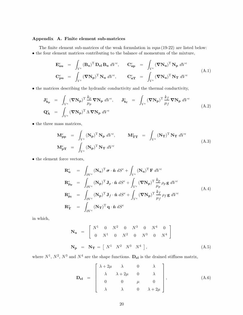
Appendix A. Finite element sub-matrices
The finite element sub-matrices of the weak formulation in eqns (19-22) are listed below:• the four element matrices contributing to the balance of momentum of the mixture,
Eeuu =
∫
V e
(Bu)T DelBu dV e, Ce
up =
∫
V e
(∇Nu)TNp dV e
Cepu =
∫
V e
(∇Np)TNu dV e, Ce
uT =
∫
V e
(∇Nu)TNT dV e
(A.1)
• the matrices describing the hydraulic conductivity and the thermal conductivity,
Jekp
=
∫
V e
(∇Np)T kpµp
∇Np dV e, Jekf
=
∫
V e
(∇Np)T kfµf
∇Np dV e
QeΛ =
∫
V e
(∇Np)T Λ∇Np dV e
(A.2)
• the three mass matrices,
Mepp =
∫
V e
(Np)T Np dV e, Me
TT =
∫
V e
(NT)T NT dV e
MepT =
∫
V e
(Np)T NT dV e
(A.3)
• the element force vectors,
Reu =
∫
∂V e
(Nu)Tσ · n dSe +
∫
V e
(Nu)T F dV e
Repp
=
∫
∂V e
(Np)T Jp · n dSe +
∫
V e
(∇Np)T kpµp
ρp g dV e
Repf
=
∫
∂V e
(Np)T Jf · n dSe +
∫
V e
(∇Np)T kfµf
ρf g dV e
ReT =
∫
∂V e
(NT)T q · n dSe
(A.4)
in which,
Nu =
[N1 0 N2 0 N3 0 N4 0
0 N1 0 N2 0 N3 0 N4
]
Np = NT =[N1 N2 N3 N4
], (A.5)
where N1, N2, N3 and N4 are the shape functions. Del is the drained stiffness matrix,
Del =
λ+ 2µ λ 0 λ
λ λ+ 2µ 0 λ
0 0 µ 0
λ λ 0 λ+ 2µ
, (A.6)
20

and Bu is the strain displacement matrix,
Bu =
∂N1
∂r0
∂N2
∂r0
∂N3
∂r0
∂N4
∂r0
0∂N1
∂z0
∂N2
∂z0
∂N3
∂z0
∂N4
∂z
∂N1
∂z
∂N1
∂r
∂N2
∂z
∂N2
∂r
∂N3
∂z
∂N3
∂r
∂N4
∂z
∂N4
∂r
N1
r0
N2
r0
N3
r0
N4
r0
, (A.7)
where r and z are the radial and the axial coordinates for the axi-symmetric case. Note that,in equations (A.5), the shape functions are the same for all primary variables.
Appendix B. Definition of the matrices K and D in eqn (24)
Identification of the sub-matrices of the stiffness matrix K and of the diffusion matrix D,equation (24).
Keuu = Ee
uu, Keupp
= −ξpCeup
Keupf
= −ξf Ceup, Ke
uT = −cT /c CeuT
Kepppp
= −Jekp
− ηMepp, Ke
pppf= ηMe
pp
Kepfpf
= −Jekf
− ηMepp, Ke
pfpp= ηMe
pp
KeTT = −Qe
Λ.
(B.1)
and,
Depp u = −ξpC
epu, De
pp pp= −appM
epp
Depp pf
= −apf Mepp, De
pp T = −apT MepT
Depf u
= −ξf Cepu, De
pf pp= −apf M
evpp
Depf pf
= −aff Mepp, De
pf T= −afT Me
pT
DeTu = −cT /c (Ce
uT)T, De
Tpp= −T 0 apT (Me
pT)T
DeTpf
= −T 0 afT (MepT)
T, DeTT = −aTT Me
TT
(B.2)
References
[1] L.L. Lake, R.L. Schmidt and P.B. Venuto, A niche for enhanced oil recovery in the 1990s,Schlumberger Oilfield Review: January, pp. 55-61, 1992.
[2] D.F. McTigue, Flow to a heated borehole in porous thermoelastic rock: analysis, WaterResources Research, 1990, 26(8), 1763-1774.
[3] D.F. McTigue, Thermoelastic Response of Fluid-saturated porous rock, Journal of Geo-physical Research, 1986, 91, 9533-9542.
21

[4] Y. Wang and E. Papamichos, Conductive heat flow and thermally induced fluid flow arounda well bore in a poroelastic medium, Water Resources Research, 1994, 30(12), 3375-3384.
[5] X. Chen, C.P. Tan and C.M. Haberfield, Guidelines for efficient wellbore stability analysis,International Journal of Rock Mechanics & Mining Sciences, 1997, 34, 3-4.
[6] G. Chen and R.T. Ewy, Thermoporoelastic effect on Wellbore stability, Society ofPetroleum Engineers Journal, 2005, 10(2), 121-129.
[7] M.K. Rahman, D. Naseby and S.S. Rahman, Borehole collapse analysis incorporating time-dependent pore pressure due to mud penetration in shales, Journal of Petroleum Scienceand Engineering, 2000, 28, 13-31.
[8] J. Zhang, M. Bai and J.C. Roegiers, Dual-porosity poroelastic analyses of wellbore stability,International Journal of Rock Mechanics & Mining Sciences, 2003, 40, 473-483.
[9] G. Chen, M.E. Chenevert, M.M. Sharma and M. Yu, A study of wellbore stability inshales including poroelastic, chemical, and thermal effects, Journal of Petroleum Scienceand Engineering, 2003, 38, 167-176.
[10] Y. Abousleiman and S. Ekbote, Solutions for the Inclined Borehole in a PorothermoelasticTransversely Isotropic Medium, ASME Journal of Applied Mechanics, 2005, 72, 102-114.
[11] Y. Wang and M.B. Dusseault, A coupled conductive-convective thermo-poroelastic solutionand implications for wellbore stability, Journal of Petroleum Science, 2003, 38, 187-198.
[12] W.K.S. Pao, R.W. Lewis and I. Masters, A fully coupled hydro-thermo-poro-mechanicalmodel for black oil reservoir simulation, International Journal for Numerical and AnalyticalMethods in Geomechanics, 2001, 25, 1229-1256.
[13] M.A. Biot, General theory of three-dimensional consolidation, Journal of Applied Physics,1941, 12, 155-164.
[14] G.I. Barenblatt, U.P. Zheltov and G.H. Kochina, Basic Concepts in the Theory of Seepageof Homogeneous Liquids in Fissured Rocks, Journal of Applied Mathematics and Mechan-ics, English Translation, 1960, 24, 1286-1303.
[15] I. Masters, W.K.S. Pao and R.W. Lewis, Coupling Temperature to a Double-porosity modelof deformable porous media, International Journal for Numerical Methods in Engineering,2000, 49, 421-438.
[16] N. Khalili and A.P.S. Selvadurai, A Fully Coupled Constitutive Model for Thermo-Hydro-Mechanical Analysis in elastic media with double porosity, Geophysical Research Letters,2003, 30(24), 7-1.
[17] R. Nair, Y. Abousleiman and M.M. Zaman, A Finite Element Porothermoelastic Model fordual-porosity media, International Journal for Numerical Methods in Engineering, 2004,28, 875-898.
[18] R. Nair, Y. Abousleiman and M.M. Zaman, An application of the dual-porosity porother-moelastic approach in naturally fractured porous media, Poromechanics II, Auriault J.L.et al. eds, 2nd Biot Conference on Poromechanics, Grenoble, France, August 26-28, 2002,Swets & Zeitlinger, 2002, 509-514.
22

[19] N. Khalili and S. Valliappan, Unified Theory of Flow and Deformation in double porousmedia, European Journal of Mechanics - A/Solids, 1996, 15(2), 321-336.
[20] N. Khalili, Two-phase fluid flow through fractured porous media with deformable matrix,Water Resources Research, 2008, 44, 1-12.
[21] B. Loret and N. Khalili, Thermo-mechanical potentials for unsaturated soils, CISM Coursesand Lectures no. 426 ‘Advanced Numerical Applications and Plasticity in Geomechanics’,Udine, 2000, Edited by D.V. Griffiths and G. Gioda, Springer Wien New York, 253-276.
[22] N. Khalili and B. Loret, An elasto-plastic model for non-isothermal analysis of flow anddeformation in unsaturated porous media: formulation, International Journal of Solids andStructures, 2001, 38(46-47), 8305-8330.
[23] B. Loret and N. Khalili, A three-phase model for unsaturated soils, International Journalfor Numerical and Analytical Methods in Geomechanics, 2000, 24, 893-927.
[24] J.B. Warren and P.J. Root, The Behaviour of Naturally Fractured Reservoirs, Society ofPetroleum Engineers Journal, 1963, 3, 245-255.
[25] N. Khalili, Coupling effects in double porosity media with deformable matrix, GeophysicalResearch Letters, 2003, 30(22), 2153.
[26] N. Khalili, S. Valliappan and C.F. Wan, Consolidation of Fissured Clays, Geotechnique,1999, 49(1), 75-89.
[27] J. Bear and M.Y. Corapcioglu, A mathematical model for consolidation in a thermoelasticaquifer due to hot water injection or pumping, Water Resources Research, 1981, 17, 723-736.
[28] T.J.R. Hughes, The Finite Element Method. Linear Static and Dynamic Finite ElementAnalysis, Prentice-Hall Inc., Englewood Cliffs, New Jersey, 1987.
[29] R.K. Wilson and E.C. Aifantis, On the Theory of consolidation with double porosity,International Journal of Engineering Science, 1982, 20(9), 1009-1035.
[30] J. Kestin, A Course in Thermodynamics, Hemisphere Pub, 1979, Waltham, Massachussets:Blaisdell Pub. Co, Volume 2.
[31] D.C. Drucker and W. Prager, Soil mechanics and plastic analysis for limit design, Quarterlyof Applied Mathematics, 1952, 10(2), 157-165.
[32] R.W. Zimmerman, T. Hadgu and G.S. Bodvarsson, Development of a dual-porositymodel for vapor-dominated fractured geothermal reservoirs using a semi-analytical frac-ture/matrix interaction term, Proceedings, Eighteenth Workshop on Geothermal ReservoirEngineering, Stanford University, Stanford, California, January 26-28 1993.
[33] M. Lu and L.D. Connell, A dual-porosity model for gas reservoir flow incorporating ad-sorption behaviour-part I. Theoretical development and asymptotic analyses, Transport inporous media, 2007, 68(2), 153-173.
23
![Deep Borehole Field Test Laboratory and Borehole Testing ... · The characterization borehole (CB) is the smaller-diameter borehole (i.e., 21.6 cm [8.5”] diameter at total depth),](https://img.dokumen.tips/doc/110x75/5ebe68817151f10bcd35645a/deep-borehole-field-test-laboratory-and-borehole-testing-the-characterization.jpg)