Embed Size (px)
Citation preview

Boolean Algebra
• 1854, George Boole created a two valued algebraic system which is now called Boolean algebra.
• 1938, Claude Shannon adapted Boolean algebra to analyze and describe the behavior of circuits built with relays. This adaptation is called switching algebra.

Switching Algebra
• In switching algebra the condition of a logic signal is represented by symbolic variables, such as x, y, and/or z, and these variables can only have two values, 0 or 1.
• Two possible conventions:– Positive Logic.
• Where LOW = 0 and HIGH = 1.
– Negative Logic.• Where LOW = 1 and HIGH =0.

Axioms• The axioms or postulates of a
mathematical system are a minimum set of basic definitions that are assumed to be true, and from which all other information about the system can be derived.
• The axioms stated below embody the “digital abstraction” by formally stating that X can take on only one of two values.– (A1) X = 0 if X 1– (A1’) X = 1 if X 0

Axioms
• Complement.– (A2) If X = 0, then X’ = 1.– (A2’) If X = 1, then X’ = 0.
• Notation.
X
X'
X~
X

Axioms• Logical multiplication ( ).
• (A3) 0 0 = 0• (A4) 1 1 = 1 • (A5) 0 1 = 1 0 = 0
• Logical addition ( + ).• (A3’) 1 + 1 = 1 • (A4’) 0 + 0 = 0 • (A5’) 1 + 0 = 0 + 1 = 1

Precedence
• By convention, the precedence of operations in a logic expression is the following:– Parentheses.– Complement.– Multiplication.– Addition.

Theorems
• Theorems are statements, known to be always true, that are used to manipulate algebraic expressions to allow simpler analysis or more efficient synthesis of circuits.
• Identities.• (T1) X + 0 = X• (T1’) X 1 = X
• Null elements.• (T2) X + 1 = 1• (T2’) X 0 = 0
• Idempotency.• (T3) X + X = X • (T3’) X X = X

Theorems
• Involution.• (T4) (X’)’ = X
• Complements.• (T5) X + X’ = 1• (T5’) X X’ = 0
• Proofs.– Theorems T1 through T5’ can
be proved by using a technique called perfect induction.
– Since a switching variable can take on only two different values, 0 or 1 by Axiom A1, we can prove a theorem involving a single variable by showing that the theorem is true for both X=0 and X=1.

Theorems
• Proof of theorem (T2).
X + 1 = 1
• Two cases:– X = 0
• 0 + 1 = 1 is true according to A5’.
– X = 1• 1 + 1 = 1 is true according to A3’.

Theorems• Commutativity.
– (T6) X + Y = Y + X
– (T6’) X Y = Y X
• Associativity.– (T7) (X + Y) + Z = X + (Y + Z)
– (T7’) (X Y) Z = X (Y Z)
• Distributivity.– (T8) X Y + X Z = X (Y + Z)
– (T8’) (X + Y) (X + Z) = X + Y Z
• Comments.– Ambiguity of X+Y+W+Z from
a strictly algebraic point of view.
– Proofs, same as before, perfect induction.

Theorems• Covering (absorption).
– (T9) X + X Y = X
– (T9’) X (X + Y) = X
• Combining.– (T10) X Y + X Y’ = X
– (T10’) (X + Y) (X + Y’) = X
• Consensus.– (T11) X Y + X’ Z + Y Z
= X Y + X’ Z
– (T11’) (X + Y) (X’ + Z) (Y + Z)
= (X + Y) (X’ + Z)
• Comments.– T9 and T10 are used in minimization
of logic functions.
– T10 used to eliminate timing hazards and to find prime implicants (iterative consensus method).

Theorems
• Proof of theorem (T9).
X + X Y = X(T1’)
X 1 + X Y = X (T8)
X (1 + Y) = X (T2)
X 1 = X (T1’)
X = X
• Proof of theorem (T10).
X Y + X Y’ = X (T8)
X (Y + Y’) = X (T5)
X 1 = X (T1’)
X = X

Theorems
• Any expression can be substituted for X, Y and Z in the previous theorem.
• For example:
Simplify W = A’BC + A’.Substitute X = A’ and Y = BC.
W = XY + X
According to theorem (T9)
XY + X = X
Therefore
W = X = A’

Theorems
• Simplify:
W = [A + B’C + DEF] [A + B’C + (DEF)’] Substitute X = A + B’C and Y = DEF
W = [X + Y] [X + Y’]
According to theorem (T10’) [X + Y] [X + Y’] = X
Therefore
W = X = A + B’C

Theorems• Generalized Idempotency.
– (T12) X + X + … + X = X– (T12’) X X … X = X
• DeMorgan’s Theorem.– (T13) (X1 X2 … Xn)’ =
X1’ + X2’ + … + Xn’
– (T13’) (X1 + X2 + … + Xn)’ =
X1’ X2’ … Xn’

Theorems• Generalized DeMorgan’s
Theorem.– (T14) [F(X1 , X2 , … , Xn,+,)]’ =
[F(X1’, X2’, … , Xn’,,+)]
• Example:– (X Y + W Z)’ = (X’ + Y’) (W’ + Z’)
• Shannon’s Expansion Theorem.– (T15) F(X1,X2, … ,Xn) =
X1 F(1,X2, … ,Xn) + X1’ F(0,X2, … ,Xn)
– (T15’) F(X1,X2, … ,Xn) =
X1 + F(0,X2, … ,Xn) X1’ + F(1,X2, … ,Xn)

Theorems
• The theorems with n variables can be proved with the finite induction technique. With finite induction, first you prove that the theorem is true for the case where n = 2 (basis step), then you prove that if the theorem is true for n = i, then it is also true for n = i + 1 (induction step).

Theorems
• Ex: Prove theorem (T12)
X + X + … + X = X
• Basis step.
X + X= X true by (T3).
• Induction step.
X + X + X = X
(X + X) + X = X
(X) + X = X
X = X + X + X

Principle of Duality• Every algebraic expression
deducible from the postulates of Boolean Algebra remains valid if the operators and identity elements are interchanged.
• Ex:– X + X Y = X– X (X + Y) = X
• Do not do this:– X + X Y = X– X X + Y = X– X + Y = X

Principle of Duality
• Formal definition:– FD(X1 , X2 , … , Xn,+,,’) =
F(X1, X2 , … , Xn,,+,’)

Standard Representation of Logic Functions
• Truth table is a table of all possible combinations of the variables showing the relationship between the values that the variables may take and the result of the operation.
A B A+B0 0 00 1 11 0 11 1 1

Standard Representation of Logic Functions
• Literal is a primed or unprimed variable.– X, X’
• Product Term is a single literal or the logical product of two or more literals.– X, X Y, X’ Y Z
• Sum of Products Expression is a logical sum of product terms.– X’ + W Y + X Y Z

Standard Representation of Logic Functions
• Sum Term is a single literal or the logical sum of two or more literals.– X, X’ + Y, X + Y’ + Z’
• Product of Sums Expression is a logical product of sum terms.– X (W + Y) ( X’ + Y + Z)
• Normal Term is a product or sum term in which a variable appears only once.– X’ Y Z, X + Y’ + Z’ (normal
terms)– X’ Y Y Z, X + X + Y’ + Z’
(non-normal terms)

Standard Representation of Logic Functions
• n-Variable Minterm is a normal product term with n literals.– For n = 3
• X’ Y Z
• n-Variable Maxterm is a normal sum term with n literals.– For n = 4
• W’ + X + Y’ + Z

Standard Representation of Logic Functions
• Minterm number is a n-bit integer used to represent a minterm.
• Maxterm number is a n-bit integer used to represent a maxterm.
Number X Y Z Minterm Maxterm0 0 0 0 X' Y' Z' X+Y+Z1 0 0 1 X' Y' Z X+Y+Z'2 0 1 0 X' Y Z' X+Y'+Z3 0 1 1 X' Y Z X+Y'+Z'4 1 0 0 X Y' Z' X'+Y+Z5 1 0 1 X Y' Z X'+Y+Z'6 1 1 0 X Y Z' X'+Y'+Z7 1 1 1 X Y Z X'+Y'+Z'
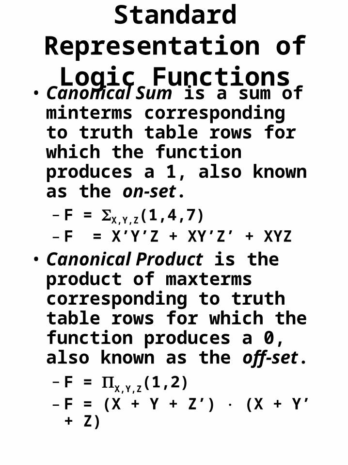
Standard Representation of Logic Functions
• Canonical Sum is a sum of minterms corresponding to truth table rows for which the function produces a 1, also known as the on-set.– F = X,Y,Z(1,4,7)– F = X’Y’Z + XY’Z’ + XYZ
• Canonical Product is the product of maxterms corresponding to truth table rows for which the function produces a 0, also known as the off-set.– F = X,Y,Z(1,2)– F = (X + Y + Z’) (X + Y’ + Z)

Standard Representation of Logic Functions
• It is easy to convert from a minterm list to a maxterm list and vice versa.
• For a function of n variables, the possible minterm and maxterm numbers are in the set {0,…,2n – 1}.
• A minterm or maxterm list is a subset of these numbers. Therefore to switch between list types, take the set complement.

Standard Representation of Logic Functions
• Ex: X,Y,Z(1,4,7) = X,Y,Z(0,2,3,5,6,)
X,Y(1,2) = X,Y(0,3)

Combinational Circuit Analysis and Synthesis
• Analysis:– Given a logic diagram:
• Find out what the circuit does.
• Find out it’s boolean function.
• Obtain a formal description of the circuit’s logic function.
• Synthesis:– Given a problem statement:
• Design the circuit.
• Obtain the logic diagram.

Combinational Circuit Analysis

Combinational Circuit Analysis
• Use basic axioms of switching algebra to derive the truth table for the circuit under analysis.
• Truth table would be the final result.
• Number of input combinations grows exponentially.

Combinational Circuit Analysis
X Y Z F0 0 0 00 0 1 10 1 0 10 1 1 01 0 0 01 0 1 11 1 0 01 1 1 1

Combinational Circuit Analysis
• Start at the inputs and propagate expressions through the gates towards the output.
• F = ((X+Y’)Z)+(X’YZ’)

Combinational Circuit Analysis
• Sum of products form.
• F = ((X + Y’) Z) + (X’YZ’)
• Multiply out.
• F = XZ + Y’Z + X’YZ’

Combinational Circuit Analysis
• Product of sums form.• F=((X+Y’)Z)+(X’YZ’)• Add out.• F=(X+Y’+X’)(X+Y’+Y)(X+Y’+Z’)
(Z+X’)(Z+Y)(Z+Z’)• F=(X+Y’+Z’)(Z+X’)(Z+Y)

NAND and NOR Gates
NAND NOR(XY)' (X+Y)'
0 0 1 10 1 1 01 0 1 01 1 0 0
YX

Combinational Circuit Analysis
• Using DeMorgan’s Theorem to simplify circuits with NAND and NOR gates.
• F=[((WX’)’Y)’+(W’+X+Y’)’+(W+Z)’]’
• F=((W’+X)’+Y’)’(WX’Y)’(W’Z’)’• F=((WX’)’Y)(W’+X+Y’)(W+Z)• F=((W’+X)Y)(W’+X+Y’)(W+Z)

Combinational Circuit Analysis
• F=[((WX’)’Y)’+(W’+X+Y’)’+(W+Z)’]’
• F=((W’+X)’+Y’)’(WX’Y)’(W’Z’)’• F=((WX’)’Y)(W’+X+Y’)(W+Z)• F=((W’+X)Y)(W’+X+Y’)(W+Z)

Exclusive-OR Gate
• An exclusive-OR gate is a two input device whose output is 1 if exactly one of its inputs is 1.
• Also known as an XOR gate.
• F=X’Y+XY’=XY
X Y F0 0 00 1 11 0 11 1 0

Combinational Circuit Synthesis
• The problem is stated.• The number of input and output
variables is determined and variable names are assigned to them.
• The truth table that defines the required relationship between inputs and outputs is derived.
• The simplified Boolean function for each output is obtained.
• Logic diagram is drawn.

Combinational Circuit Synthesis
• Design a circuit to convert a 3 bit binary number into a 3 bit gray code number.– 3 inputs labeled A, B, and C.– 3 outputs labeled X, Y, and Z.
A B C X Y Z0 0 0 0 0 00 0 1 0 0 10 1 0 0 1 10 1 1 0 1 01 0 0 1 1 01 0 1 1 1 11 1 0 1 0 11 1 1 1 0 0

Combinational Circuit Synthesis
• X=AB’C’+AB’C+ABC’+ABC
• X=A(B’C’+B’C+BC’+BC)
• X=A
• Y=A’BC’+A’BC+AB’C’+AB’C
• Y=A’B(C’+C)+AB’(C’+C)
• Y=A’B+AB’=AB
• Z=A’B’C+A’BC’+AB’C+ABC’
• Z=B’C(A’+A)+BC’(A’+A)
• Z=B’C+BC’= BC

Combinational Circuit Synthesis
• X=A
• Y=A’B+AB’=AB
• Z=B’C+BC’= BC

Circuit Manipulations• Design methods described so far
use AND, OR and NOT gates.• NAND and NOR gates are faster
in most technologies than AND and OR gates.
• Most people do not develop logical propositions in terms of NAND and NOR connectives.
• Bubble to bubble design.

Circuit Manipulations

Circuit Minimization• Canonical sum of products and
canonical product of sums are uneconomical to realize.
• Number of minterms and maxterms grows exponentially with the number of input variables.
• What can be done to minimize logic functions:– Minimize number of 1st level gates.– Minimize number of inputs on each
1st level gate.– Minimize number of inputs on 2nd
level gate.
• Methods are based on theorem T10 and T10’.– XY + XY’ = X and (X+Y)(X+Y’)=X

Circuit Minimization
• Prime number detector.– 4 inputs - N3, N2, N1, and N0
– 1 output – F
0123 N,N,N,N
,11,13)(1,2,3,5,7F

Circuit Minimization
• Consider the minterms numbers 1, 3, 5, and 7 of the prime number detector logic function derived earlier.
• G=N3’N2’N1’N0+N3’N2’N1N0+
N3’N2N1’N0+ N3’N2N1N0
• G=N3’N2’N0(N1’+N1)+
N3’N2N0 (N1’+N1)
• G=N3’N2’N0+N3’N2N0
• G=N3’N0(N2’+N2)
• G=N3’N0
G(2,11,13)F0123 N,N,N,N

Circuit Minimization• G=N3’N0
G(2,11,13)F0123 N,N,N,N

Karnaugh Maps
• Graphical representation of a logical function’s truth table.
• The map for an n-input logic function is an array with 2n cells.
• The small numbers inside the each cell are the corresponding minterm numbers in the truth table. Truth table inputs are labeled from left to right ( e.g. X, Y, Z).

Karnaugh Maps• To represent a logic function on a
Karnaugh map, we simply copy the 0s and 1s from the truth table to the corresponding cell of the map.
• Notice that the cells are numbered in such a way that they differ by a single bit.
• The cell wrap around when adjacency is considered. Therefore cells 4 and 0 are adjacent.

Karnaugh Maps
• In general we can simplify a logic function by combining adjacent 1-cells whenever possible, and writing a sum of product term that covers all of the 1-cells.
• The number of adjacent 1-cells being simplified has to be a power of 2.
• F=X’YZ’+X’Y’Z+XY’Z+XYZ
• F=X’YZ’+X’Y’Z+XY’Z+XY’Z +XYZ
• F=X’YZ’+Y’Z(X’+X)+XZ(Y’+Y)
• F=X’YZ’+Y’Z+XZ

Karnaugh Maps
• A set of 2i 1-cells may be combined if there are i variables of the logic function that can take on all 2i possible combinations within that set, while the remaining n – i variables have the same value throughout that set. The corresponding product term has
n – i literals, where a variable is complemented if it appears as 0 in all of the 1-cells, and uncomplemented if if appears as 1 (page 224).

Karnaugh Maps

Karnaugh Maps
• A minimal sum of a logic function F(X1,…,Xn) is a sum of products expression for F such that no sum of product expression for F has fewer product terms, and any sum of products expression with the same number of product terms has at least as many literals (page 225).

Karnaugh Maps
• A logic function P(X1,…,Xn) implies a logic function F(X1,…,Xn) if for every input combination that P=1, then F=1 also (page 225).
• Shorthand: P F.• We may also say that “F includes
P” or that “F covers P”.

Karnaugh Maps
• A prime implicant of a logic function F(X1,…,Xn) is a normal product term P(X1,…,Xn) that implies F, such that if any variable is removed from P, then the resulting product term does not imply F (page 226).
Karnaugh Maps• Prime Implicant Theorem.
– A minimal sum is a sum of prime implicants (page 226).
• Proof (by contradiction):– Suppose that a product term P in a
minimal sum is not a prime implicant.
– According to the definition of prime implicant, it is possible to remove a literal from P to obtain a new product term P* that still implies F.
– Replacing P with P* in the presumed minimal sum, still equals F but with one fewer literal.
– Therefore, the presumed minimal sum was not minimal after all.

Karnaugh Maps
Karnaugh Maps
• Complete sum is the sum of all prime implicants of a logic function (page 227).
• A distinguished 1-cell of a logic function is an input combination that is covered by only one prime implicant
• (page 228).• An essential prime implicant of
a logic function is a prime implicant that covers one or more distinguished 1-cells (page 228).

Karnaugh Maps

Karnaugh Maps
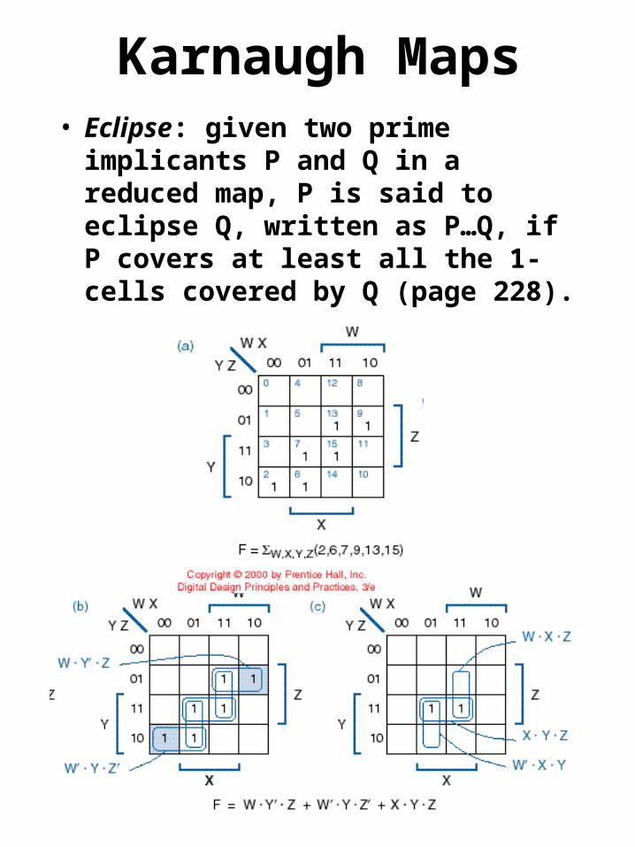
Karnaugh Maps• Eclipse: given two prime
implicants P and Q in a reduced map, P is said to eclipse Q, written as P…Q, if P covers at least all the 1-cells covered by Q (page 228).

Karnaugh Maps
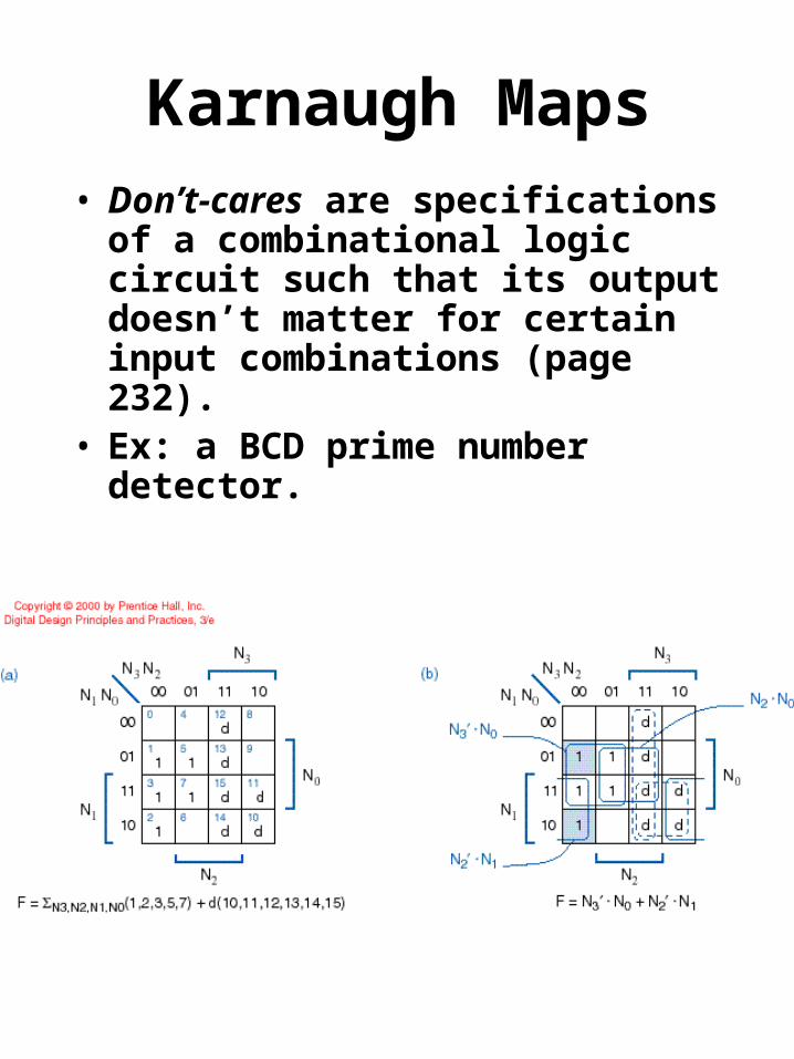
Karnaugh Maps• Don’t-cares are specifications of a
combinational logic circuit such that its output doesn’t matter for certain input combinations (page 232).
• Ex: a BCD prime number detector.

Programmed Minimization Methods
• Algorithm for the generation of prime implicants.
1. Represent each minterm of the function in its binary representation.
2. List the minterms by increasing index (the number of ones in the representation).
3. Separate the minterms into groups of equal index. Use lines to clearly separate the groups.
4. Let i=0.5. Compare each term of index i with each term
of index i+1. For each pair of minterms that differ in a single position, place a newly formed term in the section of index i of a new list, unless it is already present. Mark the two minterms that were combined. After all pairs of terms with index i and i+1 are compared, draw a line under the last term of the new list.
6. Increase i by one and repeat step 5. Continue to increase i until all terms are compared.
7. Each section of the new list has terms of equal index. Repeat steps 4, 5 and 6 to form another list. Two terms with dashes only combine if the positions of the dashes match and the terms differ in a single position.
8. The process terminates when no new list is generated. At this point the lists are checked and all terms not marked are prime implicants.

Programmed Minimization Methods
• Find the prime implicants for: F = W,X,Y,Z(1,3,4,5,9,11,12,13,14,15)
Minterm WXYZ Minterm WXYZ Minterm WXYZ1 0001 ' 1,3 00-1 ' 1,3,9,11 -0-14 0100 ' 1,5 0-01 ' 1,5,9,13 --013 0011 ' 1,9 -001 ' 4,5,12,13 -10-5 0101 ' 4,5 010- ' 9,11,13,15 1--19 1001 ' 4,12 -100 ' 12,13,14,15 11--12 1100 ' 3,11 -011 '11 1011 ' 5,13 -101 '13 1101 ' 9,11 10-1 '14 1110 ' 9,13 1-01 '15 1111 ' 12,13 110- '
12,14 11-0 '11,15 1-11 '13,15 11-1 '14,15 111- '

Programmed Minimization Methods
• Finding a minimal cover using a prime implicant table.
1. List all prime implicants (rows) and identify the minterms (columns) they represent with a check mark.
2. Identify distinguished 1-cells, the columns with a single check mark.
3. Include all essential prime implicants, the rows that contains a check in one or more distiguished 1-cell columns, in the minimal sum.
4. Remove from consideration the essential prime implicants and the minterms they represent. Delete the rows representing the essential prime implicants and the columns of the minterms they cover.
5. Remove from consideration any prime implicant that are eclipsed by others with equal or lesser cost. Delete the rows whose checked columns are a proper subset of another row’s and deleting all but one of a set of rows with identical checked columns.
6. Identify distinguished 1-cells and include all secondary essential prime implicants in the minimal sum.
7. If all the remaining columns are covered by the secondary prime implicant, we are done. Otherwise repeat from step three. In case the remaining prime implicants are not essential, do for each remaining prime implicant: pick one and treat it as if it is essential prime implicant and repeat from step 3. One more should give you a minimal sum.

Programmed Minimization Methods
• Find the prime implicants for:
F = W,X,Y,Z(1,3,4,5,9,11,12,13,14,15)
F = X’Z + XY’ + WX
WXYZ 1 3 4 5 9 11 12 13 14 15-0-1 √ √ √ √--01 √ √ √ √-10- √ √ √ √1--1 √ √ √ √11-- √ √ √ √
Minterms