Embed Size (px)
Citation preview

Bonding in Low-Coordinate Complexes What, if anything, is special?
Espen Tangen
A dissertation for the degree of Philosophiae Doctor
UNIVERSITY OF TROMSØ Faculty of Science
Centre for Theoretical and Computational Chemistry Department of Chemistry
September 2008

- 2 -
- 3 -
A DISSERTATION FOR THE DEGREE OF PHILOSOPHIAE DOCTOR
BONDING IN LOW-COORDINATE COMPLEXES
WHAT, IF ANYTHING, IS SPECIAL?
Espen Tangen September 2008
Centre for Theoretical and Computational Chemistry Department of Chemistry, Faculty of Science University of Tromsø, N-9037 Tromsø, Norway

- 4 -

Abstract
- 5 -
ABSTRACT
To contribute to the fundamental picture of the electronic structure of low-coordinate
transition metal complexes, we have carried out a series of DFT studies on mono-imido and
nitrosyl complexes for different metal ions (MnII/III, FeII/III/IV, CoII/III) and different systems of
basal ligands. These studies reveal striking similarities of the electronic structure for these
systems. The distinction of bent versus linear NO units is attributed to the ranking of the dz2
and dxz/yz parentage MOs relative to each other. Without a ligand trans to the NO group, the
antibonding metal dz2- NO σ orbital interaction is lessened by mixing in metal pz, causing the
MO to shift away from the NO ligand. This exact same orbital interaction appears to explain
the existence of middle to late first-row transition metal imido complexes.
Keywords: Transition metals, DFT, low-coordinate, imido, nitrosyl, molecular orbitals.
Front cover: The metal dz2 - imido σ orbital antibonding combination of a simple FeIV-imido model.

Acknowledgements
- 6 -
ACKNOWLEDGEMENTS
The work leading to this thesis was carried out at the Chemistry Department at the Faculty of
Science at the University of Tromsø.
I want to thank my team members – both current and former; Jeanet Conradie, Ingar
Wasbotten and Hege Ryeng for scientific and aesthetical discussions, Kathrin Hopmann for
buffering and proofreading and Emmanuel Gonzalez for providing useful references. I would
like to thank my supervisor Prof. Abhik Ghosh for introducing me to bioinorganic chemisty
and opening my eyes towards the field of science. Also, being a part of CTCC has been a
great inspiration, and also, more importantly (to me), great fun.
I want to thank Prof. Peter R. Taylor for having me as a visitor in his laboratory. Thank you
Pete, Nat, Kaz, Matt, Dave, Dev and all the other super-nice people I met in Warwick!
During the time of my PhD I have been a significant consumer of computer time, and the
support staff at the IT center at UiT, in particular Roy Dragseth and Steinar Trældal-Henden,
are gratefully acknowledged for their advice and patience. Financial support and computer
time was granted by the Research Council of Norway (NFR), both of which I acknowledge
gratefully.
My warmest gratitude goes to Brita, who has endured my shifting moods and frustration in the
finishing process. I love you!
Tromsø, September 2008
Espen Tangen

List of Included Papers
- 7 -
LIST OF INCLUDED PAPERS
The papers are ordered chronologically:
1. Tangen, E.; Svadberg, A.; Ghosh, A. "Toward Modeling H-NOX Domains: A DFT
Study of Heme-NO Complexes as Hydrogen Bond Acceptors," Inorganic Chemistry
2005, 44, 7802-7805.
2. Tangen, E.; Conradie, J.; Ghosh, A. "The Challenge of Being Straight: Explaining the
Linearity of a Low-Spin {FeNO}7 Unit in a Tropocoronand Complex," Inorganic
Chemistry 2005, 44, 8699-8706.
3. Conradie, J.; Tangen, E.; Ghosh, A. "Trigonal bipyramidal iron(III) and
manganese(III) oxo, sulfido, and selenido complexes. An electronic-structural
overview," Journal of Inorganic Biochemistry 2006, 100, 707-715.
Comment: My contribution to this work was the oxo complexes.
4. Tangen, E.; Conradie, J.; Ghosh, A. "Bonding in Low-Coordinate Environments:
Electronic Structure of Pseudotetrahedral Iron-Imido Complexes," J. Chem. Theory
Comput. 2007, 3, 448-457.
Reprints were made with permission from the copyright holders.
Abbreviations and Acronyms
- 8 -
ABBREVIATIONS AND ACRONYMS
MO = Molecular Orbital
R = organic molecule Residue (or substituent).
HF = Hartree-Fock
SCF = Self Consistent Field
TBP = Trigonal BiPyramidal
SQP = SQuare Pyramidal
CFT = Crystal Field Teory
TMC = Transition Metal Complexes
LCAO = Linear Combination of Atomic Orbitals
AO = Atomic Orbital
LFT = Ligand Field Theory
HOMO = Highest Occupied Molecular Orbital
LUMO = Lowest Unoccupied Molecular Orbital
(Por) = Porphine
ImH = Imidazole
SOMO = Singly Occupied Molecular Orbital
TC = TropoCoronand
TBPeq = TBP with the NO-group in the equatorial postion TBPax = TBP with the NO-group in the axial position
(tam) = Tropo AmiMinato
(me2tam) = DiMethyl-tam
EAN = Effective Atomic Number rule
MEC = Maximum Electron Count
Im = Imido
Ar = Aryl
OEP = ß-OctaEthyl-Porphyrin
Table of contents
- 9 -
TABLE OF CONTENTS
1 INTRODUCTION ..................................................................................................................................... 11 2 COMPUTATIONAL CHEMISTRY ....................................................................................................... 13
2.1 BASIC QUANTUM CHEMISTRY ..................................................................................................................... 13 2.2 WAVEFUNCTION-BASED METHODS ............................................................................................................. 16 2.3 DENSITY FUNCTIONAL THEORY .................................................................................................................. 17
Performance of DFT in the Bioinorganic Area ........................................................................................... 19 2.4 COMPUTATIONAL DETAILS OF PRESENTED WORK ...................................................................................... 20
3 FUNDAMENTAL STRUCTURAL CONCEPTS ................................................................................... 23 3.1 INTRODUCTION TO TRANSITION METAL COORDINATION ............................................................................ 23
Structures of Coordination Compounds ...................................................................................................... 23 3.2 INTRODUCTION TO CRYSTAL FIELD THEORY ............................................................................................... 25
Octahedral Coordination Complexes .......................................................................................................... 26 Tetrahedral Coordination Complexes ......................................................................................................... 26 Crystal Field Strength and Electron Distribution........................................................................................ 27
3.3 INTRODUCTION TO MOLECULAR ORBITAL THEORY .................................................................................... 28 Introduction to Ligand Field Theory ........................................................................................................... 29
4 LOW COORDINATE IMIDO AND NO COMPLEXES....................................................................... 31 4.1 LOW COORDINATE NITROSYL COMPLEXES ................................................................................................. 31
Introduction to Nitrogen Chemistry ............................................................................................................. 31 Transition Metal Nitrosyl Complexes .......................................................................................................... 33 5- and 6-coordinate Heme NO Complexes .................................................................................................. 39 5-coordinate Terminal Transition Metal Nitrosyls ...................................................................................... 42 4-coordinate Terminal Transition Metal Nitrosyls ...................................................................................... 48
4.2 LOW COORDINATE IMIDO COMPLEXES ........................................................................................................ 49 Introduction to Imido Ligands ..................................................................................................................... 49 3-coordinate Trigonal-Planar Imido Complexes ......................................................................................... 52 4-coordinate First-row Transition Metal Terminal Imides ......................................................................... 53 5-coordinate First-row Transition Metal Terminal Imides ......................................................................... 58
5 CONCLUSIONS ........................................................................................................................................ 63 R EFERENCES ................................................................................................................................................... 65

Table of contents
- 10 -

Introduction
- 11 -
1 INTRODUCTION
Many life-critical processes require metal ions, including respiration, nitrogen fixation,
photosynthesis, nerve transmission and muscle contraction.1 The role of the metal varies
across structural to catalytic. Transition metal ions have a rich chemistry due to close-lying
energy bands made up of partly filled d-orbitals, and thus serve as unique agents in a variety
of biological processes. In particular, this is the case for the middle and late first-row
transition metal ions, with typically single occupation of at least some of their d-orbitals. For
these elements, tuning the ligand field by the use of different ligands provides a useful way of
influencing structure, spin state and bond-order. Unperturbed FeIII and MnII ions would
typically be high-spin d5, but in bioinorganic complexes ions display all possible spin states
from S = 1/2 to S = 5/2. In essence, local structure about the metal plays an essential role
for catalytic mechanisms.
From the many beautiful studies of bioinorganic systems, synthetic, structural, spectroscopic
or computational, principles have emerged that tie together seemingly unrelated facts.1 In this
work, search for such facts is the primary aim. On the basis of a thorough MO description of
selected molecules, we have derived general concepts about bonding patterns in low-
coordinate middle and late first-row transition metal nitrosyl and imido complexes.
The general interest in iron- and manganese imido and nitrosyl complexes stems partly from
the fact that identical or similar compounds have significant roles in biology.2, 3 The field of
transition metal nitrosyls, referring to structural and bonding aspects, was termed a
provocative subject by Enemark and Feltham4 in their ground-breaking work from early
70ties. Possibly less provocative today, the field is still of significant interest.
In this thesis, calculations on 4- and 5-coordinate transition metal imido and nitrosyl
complexes will be presented. The complexes studied include pseudotetrahedral-, square
pyramidal- and trigonal bipyramidal coordination geometries, with either apical or equatorial
NX (X being either O or R) ligands, about the metal ion. The main tool of this thesis is
Introduction
- 12 -
Density Functional Theory (DFT), which has proved itself a quite reliable tool in the area of
bioinorganic chemistry.5 The primary aim of this study is to examine the geometric and
electronic structure of low-coordinated first-row transition metal nitrosyl and imido
complexes. MO arguments derived from these examinations should lead to conclusions about
the bond structure of low-coordinate complexes in general.
Before presenting the main conclusions in Chapter 5, a brief introduction to computational
chemistry methods is presented in Chapter 2 and a brief introduction to structural theories is
presented in Chapter 3. Chapter 4 presents a general overview of low-coordinate transition
metal monoimido or –nitrosyl complexes, including our results reported in Papers 1-4.
Computational Chemistry
- 13 -
)()()()(2 2
22
xExxVdx
xdm
ψψψ=+−
h
2 COMPUTATIONAL CHEMISTRY
Computational modeling of molecules is a quite accurate method for predicting molecular
properties such as geometric and electronic structures, frequencies and relative energies. One
of its strengths is the opportunity to study species, processes and/or conditions that are
difficult to obtain in a lab. Obtaining the potential energy surface of a molecule, the electron
distribution of a short-lived intermediate, the energy differences of structural isomers and
molecule orbital occupation in radicals are examples of such.
In computational quantum chemistry, the applied models are given by quantum mechanics.
Originally, computational quantum chemistry suffered from severe limitations with respect to
the size of molecules possible to investigate. The development of more efficient computers
and more elaborate mathematical tools has overcome parts of this limitation, thus enabling
researchers to look at real- or almost real-sized systems. However, because computational
chemistry methods employ a number of approximations, and often neglect effects such as
solvent or relativistic effects, the results obtained from computational calculations should
always be treated with some degree of caution.
2.1 BASIC QUANTUM CHEMISTRY
In quantum mechanics, the state of a system is described by a wavefunction. The
wavefunction gives all possible information about the system.6 To gain knowledge about
possible future states of a quantum mechanical system from its present state, we want an
equation that tells us how the wave function changes with time and space.
For time-independent systems, the time-dependent part may be factored out, and we get the
equation known as the time-independent Schrödinger equation, named after its discoverer,
Austrian physicist Erwin Schrödinger. For a single particle system it is:

Computational Chemistry
- 14 -
)()( xExH Ψ=Ψ
)();(),( nucnucnucelelnuceltot qqqqq Ψ•Ψ=Ψ
02
ˆE
rd
rdH≥
Φ
ΦΦ
∫∫
r
r
More generally written as:
where Ψ denotes the molecular wave function, E the total energy of the state and H the
Hamiltonian operator. The Hamiltonian operator contains the kinetic and potential energy
terms for the whole system. Once the correct wavefunction is known, it is in principle
possible to extract all information about the system. Unfortunately, it is only possible to solve
the Schrödinger equation exactly for one- and two particle systems. And because of this, a
variety of methods for obtaining approximate solutions have been developed. These methods
range from methods having adjusted parameters (semiempirical methods) to highly advanced
analytical methods based on different mathematical formalisms (coupled cluster,
configuration interaction, many-body perturbation theory).
Since the electrons are significantly lighter than the nucleus, they will act differently
according to molecular motion. When the nuclei change their configuration slightly, electrons
immediately will adjust. This difference in behavior leads to a possible separation of the
wavefunction in an electronic and a nuclear part:7
This is called the Born-Oppenheimer approximation. Here qel and qnuc denote the electronic
and nuclear coordinates, respectively. The formalism (qel;qnuc) indicates that the electronic
coordinates are parametrically dependent on the nuclear coordinates. In practice, the Born-
Oppenheimer approximation implies that the electronic wavefunction can be solved in a
stationary nuclear framework.
The Variational Principle states that an approximate wavefunction has an energy which is
above or equal to the exact energy, E0:7, 8
Computational Chemistry
- 15 -
∑=
=N
iiia
1ϕφ
)()()( * rrPr rrrνμ
μ νμν φφρ ∑∑=
∑∫=2/
2|)(|2N
aa rrdN rr ψ
∑∑∑ ==μ
μμμ ν
νμμν )(PSSPN
The equality only holds if the wavefunction is exact, providing a powerful tool for solving the
wavefunction. As long as the energy keeps dropping, one is on the right track.
For a single-electron system, the eigenfunctions of the electronic Schrödinger equation can
properly be called molecular orbitals. If the system only has one nucleus, the equation can be
solved exactly, and the eigenfunctions would be hydrogen-like atomic orbitals. Naively, one
could think that these atomic orbitals or a linear combination of them would serve as a decent
starting point for constructing more complicated molecular orbitals. We would then construct
a starting guess wave function as a linear combination of atomic wave functions φ;
where the set of N functions φi comprise the basis set, each φi associated with some
coefficient ai. This construction is called the linear combination of atomic orbitals (LCAO), a
fundamental approach in quantitative molecular orbital theory.7
The charge density
where P denotes the density matrix, represents the probability of finding an electron in various
regions of space and is commonly pictured by contour maps for various planes drawn through
the molecule. 9 There is no unique definition of the number of electrons to be associated with a
given atom or nucleus in a molecule, but it is sometimes useful to perform such population
analysis.9 By substituting the basis expansion of ψa into the equation that divides the total
number of electrons into two electrons per molecular orbital;
we have;

Computational Chemistry
- 16 -
where S denotes the overlap matrix, and it is possible to interpret (PS)μμ as the number of
electrons to associated with φμ. This approach is called the Mulliken population analysis.
Assuming the basis functions are centered on atomic nuclei, the corresponding number of
electrons to be associated with a given atom in a molecule is obtained by summing over all
basis functions centered on that atom.
2.2 WAVEFUNCTION-BASED METHODS
Ab initio means “from the origin” in Latin and denotes wavefunction-based methods. The
simplest qualitative model is the Hartree-Fock (HF) approximation. Here the N-body
wavefunction is be described by a single Slater determinant of N spin orbitals. The method is
also called the self-consistent field method (SCF). In this model, each particle is assumed to
experience a mean field created by the other particles. The HF method accounts for a large
part of the electron-electron interaction, including the exchange energy. The difference
between the exact energy and the approximate HF energy is named the correlation energy. To
account for the correlation energy several different approaches are in use. This is the major
resource-consuming step in ab initio calculations. Some of these methods are mentioned in
Table 1.
Table 1. A brief description of electronic structure calculation methods. Adapted from reference 10.
Method Description Performance on accuracy SCF Orbital approximation for a single-electron
configuration Modest for structures and vibrational frequencies, poor for energetics.
MP2 Improvement on HF using perturbation theory. Good for structures and frequencies, modest for energetics.
CCSD(T) Improvement of HF theory including excited Slater determinants in the wavefunction.
Excellent for structures, frequencies and energetics when a single electronic configuration is a good initial approximation.
CASSCF Wavefunction approximation using multiple electron configurations.
Modest to reasonably good for structures, frequencies and energetics.
CASPT2 Improvement of CASSCF theory using second order perturbation theory.
Good structures and frequencies, good excitation energies, reaction energies of modest accuracy.
DFT Density-based methods with parameterized exchange and correlation.
Good structures and frequencies; more variable on energetics significantly dependent on the functional used.
In both the HF and DFT formalisms the wavefunction is represented by a determinant of one-
electron functions (orbitals). If we use a complete set of orbitals, the solution of the
Schrödinger equation would yield the exact single determinant representation, and

Computational Chemistry
- 17 -
representing the wavefunction as an expansion in a complete basis of determinants would
yield the exact solution of the wavefunction within the Born-Oppenheimer approximation.
This is a powerful concept, because increasing the number of basis functions generally would
improve the accuracy of the models, and this generally holds well for molecular modeling.
However, in some cases there are needs for having a multi-determinental representation, and
this is often the case for transition metals.11 In the more troublesome cases DFT and single-
determinental ab initio fails equally.
Table 2. Formal scaling behavior as a function of basis functions N of various electronic structure methods. Adapted from reference 7.
Scaling behavior Method(s)
N4 HF N5 MP2 N6 MP3, CISD, MP4SDQ, CCSD, QCISD N7 MP4, CCSD(T), QCISD(T) N8 MP5, CISDT, CCSDT N9 MP6 N10 MP7, CISDTQ, CCSDTQ
2.3 DENSITY FUNCTIONAL THEORY
The foundation of Density Functional Theory is the idea that the energy of the electron can be
written in terms of the electronic probability density, ρ. For a system of n electrons, ρ(r)
denotes the total electron density at a particular point r in space. The electronic energy E is
said to be a functional of the electron density, denoted E[ρ(r)], indicating that for a given
function ρ(r) there exist a single corresponding energy.12
Kohn and Sham made DFT available for computational chemistry by introducing the concept
of a non-interacting reference system built on one-electron functions.13 The Hamiltonian for
this system will have eigenvalues that are simply the sum of the one-electron eigenvalues.7
The crucial bit of cleverness is, as always, to choose the proper fictitious system to generate
the ground state density from. Then the energy expression is divided into specific components
to facilitate further analysis:
EDFT[ρ] = Tni[ρ] + Vne[ρ] + Vee[ρ] + Exc[ρ]
Computational Chemistry
- 18 -
Here Tni symbolizes the exact kinetic energy of a non-interacting system, Vne is the potential
energy generated by the interaction between electrons and nuclei, Vee is the potential energy
generated by the interaction between electrons (the Coulomb energy) and the last term
includes the correction term for the kinetic energy deriving from the interacting nature of the
electrons and all the non-classical corrections to the electron-electron repulsion energy,
conveniently lumped together in one exchange-correlation energy term.
As we see from the formula above, the kinetic energy of the non-interacting reference system,
the attraction between electrons and nuclei and the Coulombic repulsion between electrons are
calculated exactly in the Kohn-Sham approach. Unfortunately, the Hohenberg-Kohn theorems
do not state the relationship between the functional and the density.14 Thus, for a given
density, the exchange-correlation part is unknown and the challenge in DFT is to design a
functional that models Exc well and a usual approach is to handle the exchange part and the
correlation part separately.
The model functionals in use may be divided into three different subgroups; the local density
approximations, the gradient corrected approximations and the hybrid functionals. A local
density approximation computes the value of εxc (the approximated value of the exchange-
correlation term) at the position r exclusively from the local density ρ(r). Typically the
density is treated as a uniform electron gas, and the approximation may account for spin
polarization. In a gradient corrected approximation, the gradient of the electron density is also
taken into account, to adjust for the general non-uniform electron density case. The hybrid
functionals are named so because a part of the exchange contribution is taken from a Hartree-
Fock method calculation and parameterized into the functional.
The greatest advantage of DFT compared to ab initio calculations is the low computational
cost, especially for large systems. On the other hand, it is not possible to carry out systematic
improvement by taking more electron configurations into account, which you can do for ab
initio methods. The only way to improve the result is to use better functionals. Furthermore,
the typical functional is designed with respect to first and second-row elements.

Computational Chemistry
- 19 -
Performance of DFT in the Bioinorganic Area
Most computational studies of transition metal complexes with relevance to biology have
been carried out using DFT methods.10, 15, 16 With large molecular sizes and often more than
one open-shell transition metal center, bioinorganic problems are generally too demanding for
high level ab initio calculations such as CASPT2 and CCSD(T).5 On the other side, DFT has
performed well on bioinorganic problems because this method handles larger systems with
comparable accuracies for a fraction of the computational cost compared to ab initio
methods.5, 10 However, for DFT calculation results on open-shell transition metal systems
there are several known cases of imperfectly described systems.17 A recent report on the
performance and limitations of DFT assigns these errors to the delocalization error of
approximate functionals from the dominating Coulomb-term and imperfect description of
static correlation in DFT.11 The latter would typically give large errors for situations with
degeneracy or near-degeneracy – as is often the case in transition metal chemistry.
For transition metal porphyrins, DFT is known to provide reasonable to good structures.15 For
relative energies of low-lying electronic states, however, DFT displays more variable
performances. As mentioned above, the exchange part of the electron-electron interaction is
described in an approximate way using functionals in DFT, and this may be one cause to the
problem.10 The exchange part describes correlation between electrons of the same spin and is
important when discussing relative energies of different electronic states in open-shell
systems. Consequently, a precise description of the exchange is of particular importance when
the states of interest have a different number of unpaired electrons. In ab initio methods, the
exchange is handled exactly, thus high-quality ab initio methods, CCSD(T) and CASPT2 are
found to describe the relative energies of low-lying states more accurately than DFT for
transition metal complexes.10, 17 And this indicates the value of validation of DFT results
versus corresponding high level ab initio method investigations.18 Unfortunately, only a few
such studies have been carried out.
The application of quantum chemical methods to challenges in bioinorganic chemistry today
is extensive,17, 19 with corresponding need for validation. Quite recently, a few such papers
have appeared – concluding that DFT is an accurate and efficient way to describe ground state

Computational Chemistry
- 20 -
energetics of bioinorganic compounds. 17, 19, 20, 21, 22 However, the errors in relative energies
vary between a couple of tenths of an eV and up to almost 1 eV,10, 20 proving the need of
individual assessment.
MO arguments are a widely used conceptual tool in inorganic chemistry, and work by
Baerends firmly establishes the Kohn-Sham MOs as physically meaningful entities.23 Both
theoretical arguments and experimental investigations show that an analogue of Koopman´s
theorem applies to the Kohn-Sham MOs.24, 25 Thus, we are fairly confident that the MO
arguments in this thesis will hold.
2.4 COMPUTATIONAL DETAILS OF PRESENTED WORK
The choice of software and functionals is primarily pragmatically founded: The method of
DFT/PW91 was chosen after considering computational costs, performance and availability.
All the work presented in this thesis is carried out with various versions of the ADF program
package26 and most of the graphics has been provided using the ChemCraft graphical software
package.27
A majority of the calculations were performed using the PW9128 functional for both exchange
and correlation together with triple-ζ basis sets, a very fine integration mesh and tight criteria
for self consistent field convergence and geometry optimization. As a check on the
performance of the PW91 functional, some calculations were performed with the optimized
Becke (B88) exchange functional (OPTX)29 together with the Lee, Yang and Parr (LYP)30
correlation functional. The latter combination is generally termed OLYP, and we are
increasingly favoring it for transition metal applications.
Where hybrid functional energies and/or surveys of functionals are presented, the noniterative
post-SCF energies are computed on basis of the previously optimized PW91 or OLYP
geometries using the HFEXCHANGE and METAGGA keywords in ADF.26 For reference to
the functionals used, see the ADF package reference list.31 Some of these references are also
encountered in our Paper 3. For the work presented in our Paper 1, the energies associated
with hydrogen bonding were corrected for basis-set superposition error (BSSE) by the
counterpoise method. Since our work generally has been focusing on electronic structures and
Computational Chemistry
- 21 -
conceptual aspects of bonding, the performance of DFT methods compared to alternative
methods has not been heavily evaluated.
Fundamental Structural Concepts
- 22 -
Fundamental Structural Concepts
- 23 -
3 FUNDAMENTAL STRUCTURAL CONCEPTS
3.1 INTRODUCTION TO TRANSITION METAL COORDINATION
The variety of transition metal compounds stems from the diversity of available oxidation
states for the metal ions and their ability to form complexes with a wide range of ligands,32
giving a wide range of coordination numbers and geometries.33 The term transition metal is
generally restricted to that of an element with at least one ion with an incomplete outer set of
d-electrons, and for the first-row transition metals, all valence electrons on the metal are
regarded as d-electrons when the metal is in a complex. Transition metal complexes comprise
of transition metal ions covalently bonded to other ions or molecules, generally termed
ligands.
Structures of Coordination Compounds
Coordination number 3
The most symmetrical 3 coordinate arrangements are planar (having D3h geometry) and
pyramidal (having C3v geometry). This coordination number is rare for metal complexes,
because nearly all MX3 metal complexes have structures where sharing of ligands leads to a
higher coordination number for metal. A few exceptions are known, including the MN3 group
that occur in Cr/Fe(NR2)3.34
Coordination number 4
There are three principal geometries for 4-coordinate complexes; the tetrahedral geometry
(with symmetry Td), the square planar geometry (with symmetry D4h) and the irregular
arrangement of symmetry that may occur when a ligand in a trigonal bipyramidal (TBP)
arrangement is replaced by a lone pair of electrons. The square planar arrangement typically
occurs in many transition metal complexes because of the presence of additional valence shell
electrons. A substitution of one of the ligands in a tetrahedral geometry typically gives

Fundamental Structural Concepts
- 24 -
pseudotetrahedral arrangements with local symmetry C3v about the metal ion, as seen for the
iron imido complexes studied in Paper 4.
Coordination number 5
For 5-coordinate complexes, there are two principal geometries; the trigonal bipyramidal
(TBP) arrangement (having D3h symmetry) and the square pyramidal (SQP) arrangement
(having C4v symmetry) (see Figure 1 and Figure 2). For the TBP arrangement, a substitution
of one of the axial ligands typically would lower the symmetry to C3v whereas a substitution
of one of the equatorial ligands would lower the symmetry to C2v. Pentagonal planar
coordination, where two ligands are bidentate and one monodentate, is very unusual and
seems to be due to the presence of two stereochemically active lone pairs.34
Coordination number 6
There are three principal forms of distortion of an octahedron. The tetragonal distortion
(symmetrical distortion along one C4 axis) gives D4h symmetry, the rhombic distortion
(unsymmetrical distortion along one C4 axis) gives D2h symmetry and the trigonal distortion
gives D3d symmetry. The tetragonal distortion most commonly involves an elongation of one
C4 axis and in the limit two trans ligands are lost completely, leaving a square planar 4-
coordinate complex.34
3 coordination
Trigonal Planar Trigonal Pyramid
4 coordination
Trigonal Pyramid Square Planar
Figure 1. Typical geometries for 3 and 4 coordinate complexes. Adapted from Lippard and Berg.1
Fundamental Structural Concepts
- 25 -
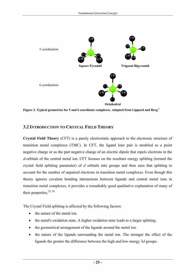
5 coordination
Square Pyramid Trigonal Bipyramid
6 coordination
Octahedral
Figure 2. Typical geometries for 5 and 6 coordinate complexes. Adapted from Lippard and Berg.1
3.2 INTRODUCTION TO CRYSTAL FIELD THEORY
Crystal Field Theory (CFT) is a purely electrostatic approach to the electronic structure of
transition metal complexes (TMC). In CFT, the ligand lone pair is modeled as a point
negative charge or as the part negative charge of an electric dipole that repels electrons in the
d-orbitals of the central metal ion. CFT focuses on the resultant energy splitting (termed the
crystal field splitting parameter) of d orbitals into groups and then uses that splitting to
account for the number of unpaired electrons in transition metal complexes. Even though this
theory ignores covalent bonding interactions between ligands and central metal ions in
transition metal complexes, it provides a remarkably good qualitative explanation of many of
their properties.35, 36
The Crystal Field splitting is affected by the following factors:
• the nature of the metal ion.
• the metal's oxidation state. A higher oxidation state leads to a larger splitting.
• the geometrical arrangement of the ligands around the metal ion.
• the nature of the ligands surrounding the metal ion. The stronger the effect of the
ligands the greater the difference between the high and low energy 3d groups.
Fundamental Structural Concepts
- 26 -
Octahedral Coordination Complexes
The splitting of the d-orbitals for a metal ion in an octahedral field serves as a good
illustration of CFT. Overall in a complex, all the d-orbitals are elevated in energy relative to a
free ion state. But because the ligands are typically oriented along the axis in a Cartesian
system for 6-coordinate octahedral complexes, the electrons in the orbitals pointing along the
axes (usually dz2 and dx2-y2) are repelled more than those in the orbitals pointing between the
axes (usually dxy, dyz and dzx). The former are raised in energy, the latter are lowered relative
to the spherical distribution and the energy of the two doubly degenerate (eg) orbitals (the dz2
and the dx2-y2) must be raised 1.5 times as much as the three triply degenerate (t2g) orbitals (the
dxy, dyz and dzx) are lowered in order to maintain balance. This is termed the Barycentre rule.
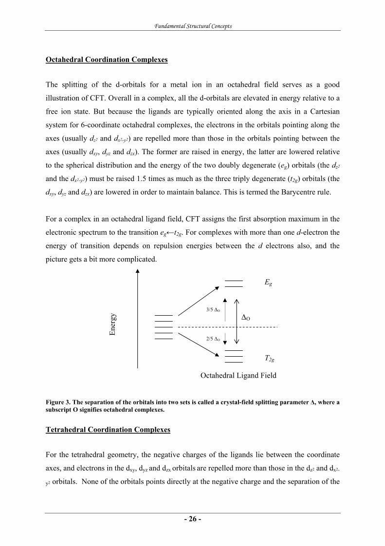
For a complex in an octahedral ligand field, CFT assigns the first absorption maximum in the
electronic spectrum to the transition eg←t2g. For complexes with more than one d-electron the
energy of transition depends on repulsion energies between the d electrons also, and the
picture gets a bit more complicated.
Figure 3. The separation of the orbitals into two sets is called a crystal-field splitting parameter Δ, where a subscript O signifies octahedral complexes.
Tetrahedral Coordination Complexes
For the tetrahedral geometry, the negative charges of the ligands lie between the coordinate
axes, and electrons in the dxy, dyz and dzx orbitals are repelled more than those in the dz2 and dx2-
y2 orbitals. None of the orbitals points directly at the negative charge and the separation of the
ΔO
Eg
T2g
Ener
gy
Octahedral Ligand Field
3/5 ΔO
2/5 ΔO

Fundamental Structural Concepts
- 27 -
two sets of orbitals are much smaller than in an octahedral ligand field. In Figure 4 the CFT
splitting is shown for a variety of relevant coordination geometries, including the tetrahedron-
derived pseudotetrahedral C3v symmetry. Most tetrahedral complexes are high-spin, with
notable exceptions studied in this work (Paper 4).
Crystal Field Strength and Electron Distribution
When there is no competition between the crystal field splitting parameter Δ and the pairing
energy Ep (the Coulombic repulsion between two electrons in an orbital), the ground state
electron configuration is unambiguous (typically octahedral d3 complex). When alternative
configurations are possible, the distinction between high- and low-spin configurations is
decided by the size of the Ep relative to Δ.
Because the Δ-value depends on both the metal and the ligands, and the spin pairing energy
varies with the metal, the decision between high- and low-spin configurations is not always
easy.
Figure 4. Crystal field splitting diagrams for relevant coordination geometries. The vertical energy axis is schematic.
E (e
V)
Oh [MX6]
Octahedron
C3v [MX5]
Trigonal bipyramid
C4v [MX5] Square
pyramid
C3v [MX4]
(pseudo) Tetrahedron
dyz
dxy
dzx
dx2-y2 dz2 dx2-y2
dx2-y2
dx2-y2
dz2
dz2
dz2
dyz
dyz
dyz
dzx
dzx
dzx
dxy
dxy
dxy

Fundamental Structural Concepts
- 28 -
iij
n
ij c χψ Σ
=
=1
3.3 INTRODUCTION TO MOLECULAR ORBITAL THEORY
Molecular Orbital Theory (MO theory) is a method for determining molecular electronic
structure by applying the orbital theory that holds for atoms onto molecules. In MO theory,
electrons are not assigned to individual bonds, but are treated as moving under the influence
of the nuclei in the whole molecule. In this theory each molecule has a set of molecular
orbitals. It is assumed that the molecular orbital wave function ψj may be written as a simple
weighted sum of the n constituent atomic orbitals χi, according to the following equation;8
where the Cij are coefficients that may be determined numerically, by substituting this
equation into the Schrödinger equation and applying the variational principle.
Figure 5. Qualitative MO diagram for NO. Adapted from McCleverty.37
2p 2p
2s 2s
σ1
σ1*
σ2
π
σ2*
π*
N atomic orbitals O atomic orbitals

Fundamental Structural Concepts
- 29 -
A molecular orbital (MO) specifies the spatial distribution and energy of one or one pair of
electrons, most commonly an MO is represented as a linear combination of atomic orbitals
from the atoms comprising the molecule (the LCAO approach). For diatomics this is easily
feasible, but for larger molecules this becomes increasingly complicated and is done by
computers. Applied onto chemical problems, the MOs are divided into bonding orbitals,
nonbonding orbitals and antibonding orbitals. The former represents a lower energy
constellation than the parentage AOs, the latter a higher energy constellation. In principle
molecules will form bonds if the atomic orbital MO combination becomes lower in energy
than the AO combination. The qualitative MO model provides a simple description of
bonding structures in molecules, and thus is a useful tool in applied computational chemistry.
Introduction to Ligand Field Theory
To overcome the conceptual weaknesses of CFT, Ligand Field Theory (LFT) was created as
a combination of CFT and MO theory. For instance the metal-ligand charge transfer (MLCT),
being hard to explain by regarding the ligands as negative point charges, is now regarded in
light of possible metal-ligand orbital overlaps and thus more conceptually feasible for LFT.
LFT also describes the bonding in coordination complexes by regarding the metal d-orbitals
and their energy levels relative to each other. The key idea is that orbitals with the same
symmetry can overlap.
Figure 6. Schematic illustrating how π-donating abilities of the ligands affects the ligand field splitting parameter.
For instance σ bonding is made up by an orbital overlap between ligand orbitals and metal ion
orbitals with σ symmetry respective to the metal-ligand (M-L) bond axis. The classification of
orbitals into σ, π and δ follows from the irreducible representation of the C∞v point group,
where the bond axis contains the highest order rotation axis (C∞). Likewise, π bonding is
made up by M-L π-orbital bonding overlap. A ligand with filled π-symmetry orbitals
energetically similar to the metal π-symmetry d orbitals, would, if having no low energy
Increasing Δ
π donor < weak π donor < no π effect < π acceptor
Fundamental Structural Concepts
- 30 -
vacant π orbitals, donates electrons to these metal orbitals and creates a bond. This donation is
depending on available empty or partly empty metal dπ orbitals. The M-L bond is somewhat
strengthened by this interaction, but the complementary antibonding MOs are typically
comparable in energy to the σ anti-bonding MO. They are filled with electrons from the metal
d-orbitals, when available, to become the HOMOs of the complex. For that reason, Δ
decreases when ligand-to-metal π- bonding occurs.
Oppositely, a π acceptor ligand has usually empty π-symmetry orbitals, typically vacant
antibonding orbitals, lower in energy than metal π-symmetry d orbitals, available for
occupation. One important π-bonding interaction in coordination complexes is the π-
backbonding. This typically occurs when the ligand LUMOs are π* orbitals and they couple
with metal dπ orbitals to form bonds. This is strengthening the metal-ligand bond and
increasing the Δ. The corresponding antibonding orbitals are higher in energy than the σ-
antibonding orbital, and the ligands end up occupying their π* orbitals and by that weakening
the bond within themself.
Low-Coordinate Imido and NO complexes
- 31 -
4 LOW-COORDINATE IMIDO AND NO COMPLEXES
4.1 LOW COORDINATE NITROSYL COMPLEXES
Introduction to Nitrogen Chemistry
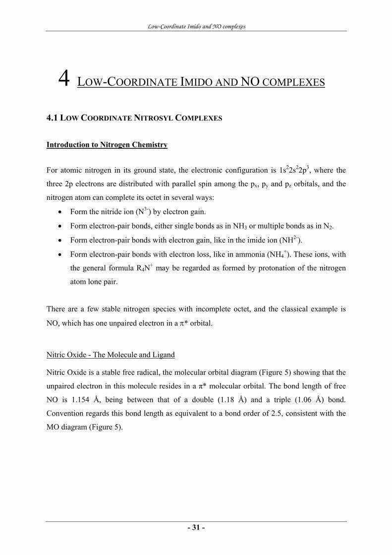
For atomic nitrogen in its ground state, the electronic configuration is 1s22s22p3, where the
three 2p electrons are distributed with parallel spin among the px, py and pz orbitals, and the
nitrogen atom can complete its octet in several ways:
• Form the nitride ion (N3-) by electron gain.
• Form electron-pair bonds, either single bonds as in NH3 or multiple bonds as in N2.
• Form electron-pair bonds with electron gain, like in the imide ion (NH2-).
• Form electron-pair bonds with electron loss, like in ammonia (NH4+). These ions, with
the general formula R4N+ may be regarded as formed by protonation of the nitrogen
atom lone pair.
There are a few stable nitrogen species with incomplete octet, and the classical example is
NO, which has one unpaired electron in a π* orbital.
Nitric Oxide - The Molecule and Ligand
Nitric Oxide is a stable free radical, the molecular orbital diagram (Figure 5) showing that the
unpaired electron in this molecule resides in a π* molecular orbital. The bond length of free
NO is 1.154 Å, being between that of a double (1.18 Å) and a triple (1.06 Å) bond.
Convention regards this bond length as equivalent to a bond order of 2.5, consistent with the
MO diagram (Figure 5).
Low-Coordinate Imido and NO complexes
- 32 -
π*
σ2
Metal d orbitals NO molecular orbitals
dxy, dx2-y2
dyz, dzx, π*(NO)
π*(NO), dyz, dzx
σ(NO), dz2
dz2, σ(NO)
M N O M N O
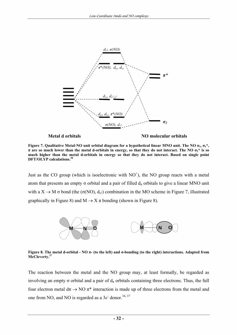
Figure 7. Qualitative Metal-NO unit orbital diagram for a hypothetical linear MNO unit. The NO σ1, σ1*, π are so much lower than the metal d-orbitals in energy, so that they do not interact. The NO σ2* is so much higher than the metal d-orbitals in energy so that they do not interact. Based on single point DFT/OLYP calculations.38
Just as the CO group (which is isoelectronic with NO+), the NO group reacts with a metal
atom that presents an empty σ orbital and a pair of filled dπ orbitals to give a linear MNO unit
with a X → M σ bond (the (σ(NO), dz2) combination in the MO scheme in Figure 7, illustrated
graphically in Figure 8) and M → X π bonding (shown in Figure 8).
Figure 8. The metal d-orbital - NO π- (to the left) and σ-bonding (to the right) interactions. Adapted from McCleverty.37
The reaction between the metal and the NO group may, at least formally, be regarded as
involving an empty σ orbital and a pair of dπ orbitals containing three electrons. Thus, the full
four electron metal dπ → NO π* interaction is made up of three electrons from the metal and
one from NO, and NO is regarded as a 3e- donor.34, 37

Low-Coordinate Imido and NO complexes
- 33 -
The Enemark-Feltham Electron Count
Due to the difficulty of assigning formal oxidation states to the metal and the NO in nitrosyl
complexes arising from the covalent nature of the M-N-O interaction, Enemark and Feltham
proposed a formalism which treated the metal nitrosyl as an inorganic functional group unit.39
This unit was represented as {MNO}n, where n is the total number of metal d-electrons plus
the number of electrons in NO exceeding those on NO+. The number of metal d electrons is
determined by the formal oxidation state of the metal atom, assuming no charge on the NO.
This formalism makes no assumption of the actual distribution of electrons between the metal
and the NO group and also makes no assumption about the M-N-O angle.
Geometry of NO Complexes
In the traditional picture, the metal-NO bonding is achieved by the NO lone pair filling into
the empty metal dz2 orbital and by backbonding through the overlap between the two metal dπ
orbitals and the NO π* orbitals.40 Terminal nitrosyl ligands may adopt either linear or bent M-
N-O geometries. Relatively few complexes have truly linear arrangements, so generally MNO
units with M-N-O angles in the range of from 160° to 180° are still regarded as linear.34 Truly
bent MNO-groups have MNO bond angles between 120° and 150°.
Transition Metal Nitrosyl Complexes
The Structure of MNO Units according to Enemark and Feltham
The diagrams in Figure 9 were constructed from the metal d- and the NO π* orbitals, which
molecular orbital calculations have shown to be similar in energy and strongly interacting.41
Because the NO ligand is a strong π-accepting ligand,42 the (dxz, dyz, π*(NO))-orbitals are
shown as the lowest MOs in all of the diagrams of Figure 9. These orbitals are bonding with
respect to M and N, but antibonding with respect to N and O. The (dxy, dx2-y2) orbitals are non-
bonding in C∞v symmetry, and the (dz2) orbital is σ-antibonding with respect to M and N.
Finally, the (π* (NO), dxz, dyz) orbitals are antibonding with respect to M, N and O. As seen
from the Figure 9, where the (π*(NO), dxz, dyz) and (dz2, σ (NO)) orbitals represent the
antibonding metal-NO interactions, we only need to consider the relative ranking of the

Low-Coordinate Imido and NO complexes
- 34 -
(π*(NO), dxz, dyz) orbitals with respect to the other orbitals to decide whether a given value on
n will produce a linear or bent MNO unit.
Figure 9. Four possible MO diagrams for the covalent MNO group in C∞v symmetry. Diagrams a) and b) represent cases where the metal d orbitals of the free ion are higher in energy than the NO π* orbitals. Diagrams c) and d) represent the cases where the metal d orbitals are of lower energy than the NO π* orbitals. The influence of n on the M-N-O angle is shown for each diagram. Adapted from reference 42.
The coordination of additional ligands to the central metal ion in a complex will lower the
symmetry from C∞v and may have significant effect on the geometry of the MNO unit. A C4v
perturbation may, for instance, convert a linear {MNO}8 group into a bent {MNO}8 group for
a molecule from the Figure 9a-category but make a bent {MNO}6 into a linear {MNO}6 for
Figure 9c-category. A relevant example of this perturbation is six-coordinate Heme-NO
complexes with an apical NO ligand, where C4v is the maximum symmetry.
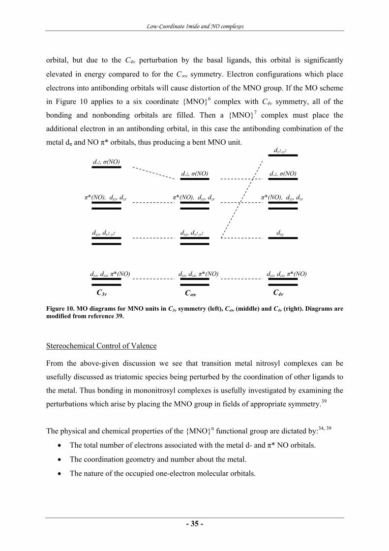
In Figure 10, the rightmost diagram illustrates the energy levels of the relevant MNO unit
orbitals in a field of C4v symmetry. The bonding combination of the metal dz2 and the NO pσ –
orbital is very low in energy, and mostly localized on the N atom of the NO, thus the lowest
orbitals displayed in the diagrams of Figure 10 are the two bonding combinations (with
respect to the M and N) of the metal dxz, dyz and the NO π* orbitals. These orbitals are
antibonding with respect to N and O. The metal dxy- orbital interacts with no NO orbital, thus
stays localized on the metal and is nonbonding. This would be the case also for the metal dx2-y2
Linear n ≤ 8 Bent n > 8
dxy, dx2-y2
dyz, dzx, π*(NO)
π*(NO), dyz, dzx
dz2, σ(NO)
dxy, dx2-y2
dyz, dzx, π*(NO)
π*(NO), dyz, dzx
dz2, σ(NO)
dyz, dzx, π*(NO)
dz2, σ(NO)
dxy, dx2-y2
π*(NO), dyz, dzx
dxy, dx2-y2
dyz, dzx, π*(NO)
π*(NO), dyz, dzx
dz2, σ(NO)
Linear n ≤ 10 Bent n > 10
Linear n ≤ 4 Bent n > 4
Linear n ≤ 6 Bent n > 6
(a) (b) (c) (d)
Low-Coordinate Imido and NO complexes
- 35 -
orbital, but due to the C4v perturbation by the basal ligands, this orbital is significantly
elevated in energy compared to for the C∞v symmetry. Electron configurations which place
electrons into antibonding orbitals will cause distortion of the MNO group. If the MO scheme
in Figure 10 applies to a six coordinate {MNO}6 complex with C4v symmetry, all of the
bonding and nonbonding orbitals are filled. Then a {MNO}7 complex must place the
additional electron in an antibonding orbital, in this case the antibonding combination of the
metal dπ and NO π* orbitals, thus producing a bent MNO unit.
Figure 10. MO diagrams for MNO units in C3v symmetry (left), C∞v (middle) and C4v (right). Diagrams are modified from reference 39.
Stereochemical Control of Valence
From the above-given discussion we see that transition metal nitrosyl complexes can be
usefully discussed as triatomic species being perturbed by the coordination of other ligands to
the metal. Thus bonding in mononitrosyl complexes is usefully investigated by examining the
perturbations which arise by placing the MNO group in fields of appropriate symmetry.39
The physical and chemical properties of the {MNO}n functional group are dictated by:34, 39
• The total number of electrons associated with the metal d- and π* NO orbitals.
• The coordination geometry and number about the metal.
• The nature of the occupied one-electron molecular orbitals.
C∞v
dxy, dx2-y2
dyz, dzx, π*(NO)
π*(NO), dyz, dzx
dz2, σ(NO)
dxy
dyz, dzx, π*(NO)
π*(NO), dyz, dzx
dz2, σ(NO)
dx2-y2
dxy, dx2-y2
dyz, dzx, π*(NO)
π*(NO), dyz, dzx
dz2, σ(NO)
C4v C3v
Low-Coordinate Imido and NO complexes
- 36 -
For n ≤ 6 all {MNO}n groups are linear or nearly so in octahedral geometry (6-coordination).
A typical example is (Por)MnII(NO)(ImH). For n ≥ 7, {MNO}n groups are bent in octahedral
geometry. Typical examples of n = 7 and n = 8 are (Por)MII(NO)(ImH) where M = Fe, Co
respectively. For 5-coordination MNO is linear for n ≤ 6, n = 8 gives linear MNO units in
TBP complexes but bent MNO units for SQP complexes. For 4-coordination, n = 10 gives a
linear MNO unit for tetrahedral coordination geometry about the metal, but a bent MNO unit
for planar geometries.
For a given class of complexes additional perturbations can be introduced by changing the
metal and/or the donor atoms of the ligands. Because the formal oxidation states of the atoms,
the geometries and chemical reactivities of the MNO group are dictated by the overall
stereochemistry of the complex ion, Enemark and Feltham introduced the collective term
“stereochemical control of valence” for these determining factors.39 In view of the differences
between the electronic structures of linear and bent MNO groups, considerable difference in
their chemical reactivity is expected.34
Structural Rules for 5-coordinate NO Complexes
In a paper from 1974 Hoffmann and coworkers43 presented a comprehensive theoretical
model of the electronic structure of 5-coordinate nitrosyls. In this paper they discuss the
relationship between the SQP geometry with a bent apical nitrosyl ligand and the TBP
geometry with a linear equatorial nitrosyl ligand, with the aim of understanding why and how
5-coordinate nitrosyl complexes bend. The answers came in the form of a set of rules (only
slightly modified from reference 43):
• The better the σ- or π-donating capabilities of the basal ligands, the more likely is the
nitrosyl to bend.
• In compounds of type ML2L´2(NO), L trans to L´ having different donor capabilities,
the nitrosyl group should bend in the plane containing the poorer donors.
• In a compound of the type ML2DA, D = π donor trans to A = π acceptor, if the NO
group bends in the DMA plane, then it should bend toward the acceptor.
• The nitrosyl is less likely to bend in the equatorial position of a trigonal bipyramid
than in the apical site of a square pyramid.
Low-Coordinate Imido and NO complexes
- 37 -
• If a nitrosyl in the equatorial position of a trigonal bipyramid bends, then it would
prefer to do so in the axial plane rather than in the equatorial one.
• Nitrosyl groups in axial positions in a trigonal bipyramid and basal sites in a square
pyramid prefer to be linearly coordinated.
• In ML4NO species, if the ligands L are strong π acceptor substituents, a trigonal
bipyramid with an equatorial nitrosyl will be preferred. If the ligands L are strong π
donors, a range from strongly bent SQP to less bent TBP of geometries is possible.
The arguments go as follows: π donor substituents will raise the energy of the metal dπ and dσ
orbitals (using notation from the C∞v point group for the MNO unit). The higher the dσ lies,
the stronger its stabilizing interaction with the NO π* in the xz-plane as it bends and the less
destabilizing its interactions with NO σ*. If the former dominates, a rising of the energy of the
dσ orbital favors bending. As will raising the xz-plane dπ orbital, by lessen its preference for
linear geometry. Thus, the net result of increase in energy of the dπ and dσ orbitals through
donor substitution is to favor bending. Conversely, basal substitution by acceptors lowers the
energy of the dπ and dσ orbitals and by that favoring MNO linearity.
If the four basal donors may be split into two groups L (in the xz plane) and L´ (in the yz
plane), the latter being a better donor than the former, then the metal dπ orbitals are no longer
degenerate. The better basal donor substituents make the metal a stronger donor in the yz
plane, and as the NO bends it loses the weaker π interaction and keeps the stronger one, thus
bending in the xz-plane. If two of the four basal ligands are constituted of one good π donor
denoted D and one good π acceptor denoted A trans to D, the basal π acceptor orbital mixes
into dπ in the DMA-plane (defined as the xz plane for convenience) in a bonding manner and
the π donor orbital mixes in an antibonding manner. This gives a secondary node between dxz
and the basal donor orbitals, but no corresponding node on the acceptor side. Then if the
nitrosyl bends, it will prefer to do so to minimize the antibonding NO σ2 - dxz interaction, by
pointing the NO σ2 toward the node and preserve the xz-plane NO π* - dxz bonding interaction
by pointing the xz-plane NO π* toward the nodeless side. In a linear geometry, the MO of
metal dz2 parentage is mostly localized on the metal with only a minor part antibonding NO σ2
mixed in. As the NO bends, the metal dz2 orbital begins to interact with the xz-plane NO π*
orbital. Thus, the NO bond weakens as the π* orbital is populated and the NO group as a

Low-Coordinate Imido and NO complexes
- 38 -
whole gains electron density from the ML4 fragment. The metal dπ orbitals are degenerate
with strong π bonding with the NO π* orbitals in the linear MNO geometry. This interaction
is gradually weakened as the NO group bends, and the expected trend is the reverse of the one
described for the metal dz2 – NO orbital interaction. The effect set by the metal dz2 orbital
dominates because this orbital is closer in energy to the nitrosyl π* orbitals than the metal dxz,
thus causing a stronger interaction.43
If the metal dz2 orbital is energetically higher than the NO π* orbitals, basal donors that raise
the energy of the former would decrease the interaction between the metal dz2 and the NO π*
orbitals, since it is now above and thus removed from the latter. The effect is a decreased
tendency to bend. The effect of a reversed order of the metal dz2 orbital relative to the NO π*
orbitals on M-L charge transfer would be an increased electronic density on the NO because
the NO π* orbitals would be populated first. Though, the M-NNO bond is not necessarily
weakened because two electrons have switched from an σ* MO to a π* MO.
Figure 11. The metal dz2-NO σ2 antibonding interaction for the SQP geometry (left) and the TBP geometry (right). For both molecules, the z-axis is along the M-NNO vector and the y-axis is along the face of the paper. The pictured molecules are provided for illustration purposes only.
For both the SQP and TBP geometries, the balance of interactions involving the dz2 orbital,
which favor bending, and the dxz and dyz orbitals, which favor linearity, imposes one or the
other. The essential difference between the linear NO structure of the SQP and TBP
geometries is that for the SQP geometry, the antibonding metal dz2 - NO σ2 combination
(illustrated in Figure 11) cannot be avoided, because the dz2 orbital is the only metal orbital of

Low-Coordinate Imido and NO complexes
- 39 -
a1 symmetry. For the TBP geometry both dz2 and dx2-y2 have the same symmetry, and the linear
combination dz2 + dx2-y2 ~ dz2-y2 (illustrated in Figure 11). This combination takes some electron
density from the laboratory z-axis and puts it into the less electronically crowded region along
the laboratory y-axis.
Figure 12. Illustration of the metal dyz-basal ligand orbital σ antibonding interaction. The pictured molecules are provided for illustration purposes only.
The distortion from SQP to TBP causes a characteristic difference between the xz and yz
directions by itself, without differential ligand substitution (which would contribute
additionally). If the axial positions in the TBP geometry are along the laboratory x-axis, the
metal dyz orbitals would be higher in energy than the metal dxz because of σ antibonding
character versus the basal ligands (Figure 12). Then the yz plane becomes the better donor
plane, and as the nitrosyl bends it should preserve the stronger metal dyz – nitrosyl π*
interaction, which implies bending in the xz plane.
5- and 6-coordinate Heme NO Complexes
General Description of MNO Unit Structures in Metalloporphyrin NO Complexes
The metalloporphyrin nitrosyls exhibit distinct MNO bond angles and serve here as an
excellent frame of reference for the discussion on low-coordinated NO complexes. For these
complexes, which in general have square pyramidal geometries in 5 coordination and
pseudoctahedral geometries in 6 coordination, the most important cases are the {MNO}n, n =
6-8, being characterized by different M-N-O bond angles of approximately linear for n = 6,
lightly bent (140°) for n = 7 and strongly bent (120°) for n = 8. These cases are exemplified

Low-Coordinate Imido and NO complexes
- 40 -
by FeIII-NO porphyrin-, FeII-NO porphyrin- and CoII-NO porphyrin complexes,
respectively.34, 37, 44
The MO diagram for a C4v perturbed MNO unit (Figure 10) gives a qualitative explanation for
this variation in M-N-O bond angles. For n ≥ 7, because of occupation of MNO antibonding
orbitals, the metal dπ in the bending plane changes its bonding character from π to σ due to the
bending. Crystallographic studies by Scheidt and coworkers44, 45 revealed that MNO unit
bending was not the only fundamental structural feature of the metalloporphyrin nitrosyls. In
addition to the expected bond angles of 144.4° for a {MNO}7 system, Ellison and Scheidt45
reported a tilting of the MNO unit for {FeNO}7 porphyrins. An [Fe(OEP)(NO)] complex
displayed a metal ion displacement of approximately 0.3 Å above the inner core porphyrin
plane (defined by the 4 pyrrole nitrogens, thus termed the N4 plane) and a 6.5° tilt of the Fe-
NNO vector from the N4 plane normal. Also, the four equatorial Fe-NPor bonds displayed a
rather large range of values, pairwise so. The geometrical features reported for this complex
were as follows: A MNO unit bond angle of 144.2°, a Fe-NNO distance of 1.722Å and an N-O
distance of 1.167Å. In an attempt to reproduce these experimental results, an even greater off
perpendicular tilt of 8.2° was found, with the other geometrical key values of 142.7°, 1.731 Å
and 1.168 Å, respectively. In a later paper, Scheidt and coworkers46 confirms the above
mentioned findings also for 5-coordinate ferrous porphyrin nitrosyl compounds. A
DFT/PW91 study by Wondimagegn and Ghosh47 assigned this tilting and equatorial
asymmetry to molecular orbital interactions.
Wyllie et al.48 report changes going from five-coordinated to six-coordinated complex for
various iron porphyrin NO complexes. Their observations indicate a destabilization of the
metal dz2 orbital and thus increasing the MNO unit bending by approximately 5°, the Fe-NNO
bond seems somewhat influenced, with an increase of approximately 0.02 Å and decrease of
the Fe-NNO off perpendicular tilt by up to as much as 4°.
Electronic Structures in 5- and 6-coordinate Heme-NO Complexes (Paper 1)
We used DFT/PW91 to study electronic and geometric structures of 5- and 6-coordinate
heme-NO complexes with the main purpose to study their H-bond acceptor abilities. 5- and
6-coordinate heme-NO active sites were modeled with (Por)Fe(NO) and (Por)Fe(NO)(ImH)
Low-Coordinate Imido and NO complexes
- 41 -
(where Por = porphine and ImH = imidazole).47 In this study, the heme-NO bonding
electronic structure was modeled and some fundamentals of heme-NO bonding were mapped,
serving as a later reference for the discussion on low coordinate transition metal nitrosyl and
imido complexes.
The optimized geometrical parameters on (Por)Fe(NO) and (Por)Fe(NO)(ImH) are in
generally good agreement with experimental metrical parameters on related 5- and 6-
coordinate iron porphyrins (See Figure 13).44, 45, 46
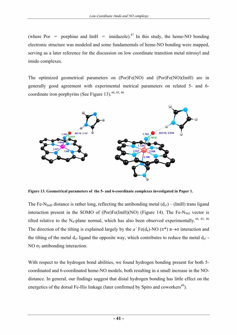
Figure 13. Geometrical parameters of the 5- and 6-coordinate complexes investigated in Paper 1.
The Fe-NImH distance is rather long, reflecting the antibonding metal (dz2) – (ImH) trans ligand
interaction present in the SOMO of (Por)Fe(ImH)(NO) (Figure 14). The Fe-NNO vector is
tilted relative to the N4-plane normal, which has also been observed experimentally.44, 45, 46
The direction of the tilting is explained largely by the a´ Fe(dπ)-NO (π*) π→σ interaction and
the tilting of the metal dz2 ligand the opposite way, which contributes to reduce the metal dz2 -
NO σ2 antibonding interaction.
With respect to the hydrogen bond abilities, we found hydrogen bonding present for both 5-
coordinated and 6-coordinated heme-NO models, both resulting in a small increase in the NO-
distance. In general, our findings suggest that distal hydrogen bonding has little effect on the
energetics of the dorsal Fe-His linkage (later confirmed by Spiro and coworkers49).
Low-Coordinate Imido and NO complexes
- 42 -
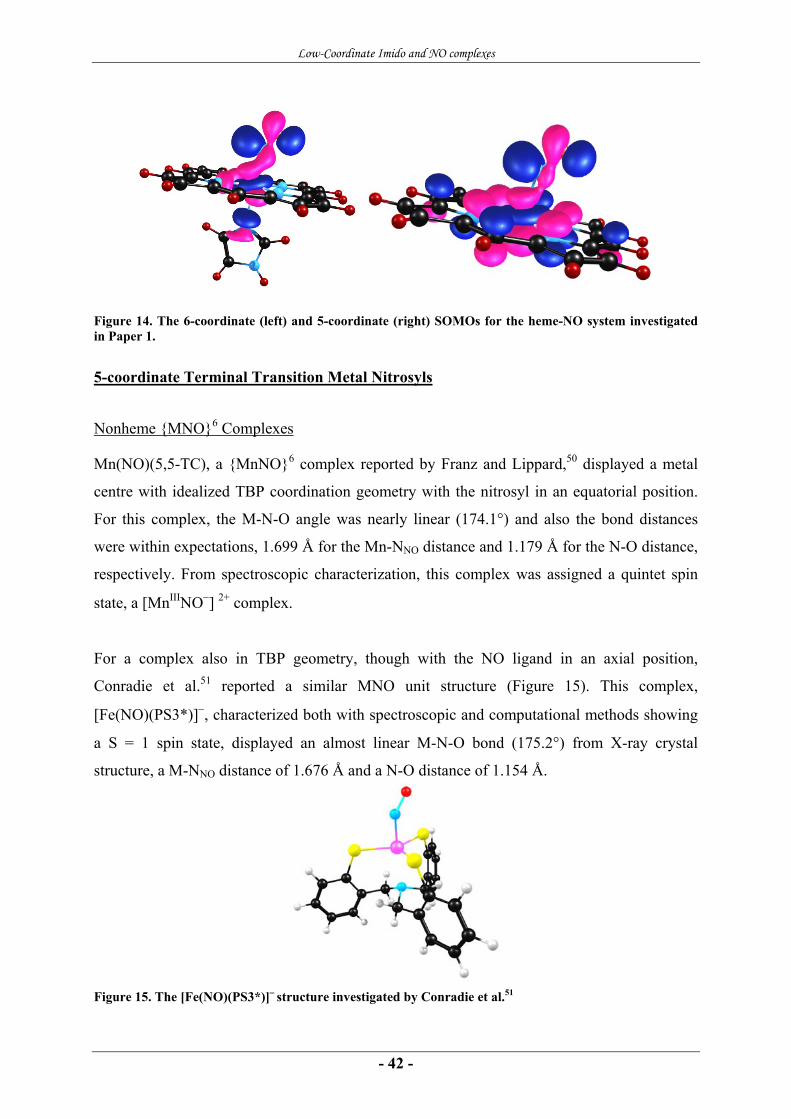
Figure 14. The 6-coordinate (left) and 5-coordinate (right) SOMOs for the heme-NO system investigated in Paper 1.
5-coordinate Terminal Transition Metal Nitrosyls
Nonheme {MNO}6 Complexes
Mn(NO)(5,5-TC), a {MnNO}6 complex reported by Franz and Lippard,50 displayed a metal
centre with idealized TBP coordination geometry with the nitrosyl in an equatorial position.
For this complex, the M-N-O angle was nearly linear (174.1°) and also the bond distances
were within expectations, 1.699 Å for the Mn-NNO distance and 1.179 Å for the N-O distance,
respectively. From spectroscopic characterization, this complex was assigned a quintet spin
state, a [MnIIINO−] 2+ complex.
For a complex also in TBP geometry, though with the NO ligand in an axial position,
Conradie et al.51 reported a similar MNO unit structure (Figure 15). This complex,
[Fe(NO)(PS3*)]−, characterized both with spectroscopic and computational methods showing
a S = 1 spin state, displayed an almost linear M-N-O bond (175.2°) from X-ray crystal
structure, a M-NNO distance of 1.676 Å and a N-O distance of 1.154 Å.
Figure 15. The [Fe(NO)(PS3*)]− structure investigated by Conradie et al.51
Low-Coordinate Imido and NO complexes
- 43 -
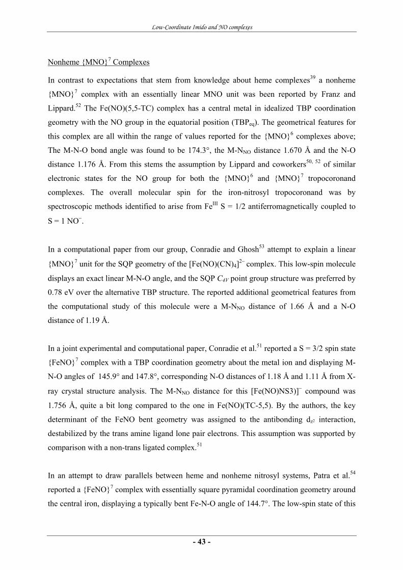
Nonheme {MNO}7 Complexes
In contrast to expectations that stem from knowledge about heme complexes39 a nonheme
{MNO}7 complex with an essentially linear MNO unit was been reported by Franz and
Lippard.52 The Fe(NO)(5,5-TC) complex has a central metal in idealized TBP coordination
geometry with the NO group in the equatorial position (TBPeq). The geometrical features for
this complex are all within the range of values reported for the {MNO}6 complexes above;
The M-N-O bond angle was found to be 174.3°, the M-NNO distance 1.670 Å and the N-O
distance 1.176 Å. From this stems the assumption by Lippard and coworkers50, 52 of similar
electronic states for the NO group for both the {MNO}6 and {MNO}7 tropocoronand
complexes. The overall molecular spin for the iron-nitrosyl tropocoronand was by
spectroscopic methods identified to arise from FeIII S = 1/2 antiferromagnetically coupled to
S = 1 NO−.
In a computational paper from our group, Conradie and Ghosh53 attempt to explain a linear
{MNO}7 unit for the SQP geometry of the [Fe(NO)(CN)4]2− complex. This low-spin molecule
displays an exact linear M-N-O angle, and the SQP C4V point group structure was preferred by
0.78 eV over the alternative TBP structure. The reported additional geometrical features from
the computational study of this molecule were a M-NNO distance of 1.66 Å and a N-O
distance of 1.19 Å.
In a joint experimental and computational paper, Conradie et al.51 reported a S = 3/2 spin state
{FeNO}7 complex with a TBP coordination geometry about the metal ion and displaying M-
N-O angles of 145.9° and 147.8°, corresponding N-O distances of 1.18 Å and 1.11 Å from X-
ray crystal structure analysis. The M-NNO distance for this [Fe(NO)NS3)]− compound was
1.756 Å, quite a bit long compared to the one in Fe(NO)(TC-5,5). By the authors, the key
determinant of the FeNO bent geometry was assigned to the antibonding dz2 interaction,
destabilized by the trans amine ligand lone pair electrons. This assumption was supported by
comparison with a non-trans ligated complex.51
In an attempt to draw parallels between heme and nonheme nitrosyl systems, Patra et al.54
reported a {FeNO}7 complex with essentially square pyramidal coordination geometry around
the central iron, displaying a typically bent Fe-N-O angle of 144.7°. The low-spin state of this

Low-Coordinate Imido and NO complexes
- 44 -
complex was by the authors from analysis of the X-ray geometry assigned to comprise an
intermediate spin FeIII antiferromagnetically coupled to a triplet spin NO−. This is in line with
what is reported also for the Fe(NO)(5,5-TC) complex.52
Table 3. Concluding the geometrical features reported for 5-coordinate nonheme transition metal complexes with terminal nitrosyl ligands.
Complex Coord.
Geom. Spin M-NNO (Å) N-O (Å) ∠ MNO (°) Ref
[(bpb)Fe(NO)] SQP 1/2 1.713 1.182 144.7 54 Fe(NO)(5,5-TC) TBPeq 1/2 1.670 1.176 174.3 52 [Fe(NO)NS3)]− TBPax 3/2 1.756 1.11
1.18 145.9 147.8
51
[Fe(NO)(CN)4]2− SQP 1/2 1.66 1.19 180 53
A Linear {FeNO}7 Low-spin Unit (Paper 2)
With DFT/PW91 we investigated the electronic and geometrical structure of the Fe(5,5-
TC)NO complex and the corresponding simplified models Fe(tam)NO and Fe(me2tam)NO
(see Figure 16). The Fe(5,5-TC)NO has previously been characterized by spectroscopic
methods,52 but our study provides an additional MO description of the complex.
tamim
N
N
H
H
N
N N
N
(CH2)m
(CH2)n
me2 tamim
m,n-TC
N
N
CH3
CH3
Figure 16. The tamim (tam), me2tamim (me2tam) and tropocoronand ligands, [m,n-TC]2- investigated in Paper 2.

Low-Coordinate Imido and NO complexes
- 45 -
{FeNO}7 S = 1/2 and S = 3/2 systems with all three ligands were optimized. We investigated
possible geometries of the complex by applying starting geometries defined as SQP, TBP with
the NO-group in the axial position (TBPax) and TBP with the NO-group in the equatorial
position (TBPeq) (see Figure 17) by applying symmetry constraints to the input. The S = 1/2
spin state was favored for all of the molecules studied, consistent with experiment,52 by a
substantial margin. Thus we did not include the S = 3/2 states in the overall discussion.
Figure 17. The SQP geometry (left), TBPax geometry (middle) and TBPeq geometry (right).
For Fe(tam)2NO, the lowest-energy conformation corresponds to SQP coordination geometry,
with the TBPeq geometry only about 0.1 eV higher in energy. For the Fe(me2tam)2NO, this is
reversed and the split is slightly larger. For both, the TBPax geometry is significantly higher in
energy. The results for Fe(5,5-TC)NO are qualitatively similar to those for Fe(me2tam)2NO;
the TBPeq geometry has the lowest energy, the SQP geometry is nearly 0.9 eV higher in
energy, and the TBPax form is higher still. The reversal of stereochemical preference between
Fe(tam)2NO, on the one hand, and Fe(me2tam)2NO and Fe(5,5-TC)NO, on the other hand,
basically indicates that alkylation of the tamim ligands, whether with methyl groups or with
the polymethylene tethers of the 5,5-TC ligand, tips the stereochemical preference from SQP
to TBPeq.
For the SQP and TBPeq geometries, none of the higher occupied MOs exhibits significant
metal-ligand antibonding interactions, whereas the SOMO as well as the majority spin
HOMO-2 and minority spin HOMO-1 in the TBPax case all exhibit significant metal-tamim σ
antibonding character (shown in Figure 18). Also, MO investigations indicate that the metal-
tamim bonding interactions are stronger for the SQP and TBPeq geometries than for the TBPax
geometry; a strong low-lying metal-tamim bonding interaction in the majority-spin HOMO-19
for the SQP and TBPeq cases has no analogue for the TBPax.

Low-Coordinate Imido and NO complexes
- 46 -
Figure 18. The majority spin HOMOs (SOMOs) of the investigated tamim complexes.
For the TBPeq geometry of Fe(tam)2NO and Fe(5,5-TC), the electronic configuration of the
metal may be described as (dxz, dyz)4dxy2dx2-z2
1 and the majority-spin HOMO-2 may be viewed
as Fe dxy-based. The SOMO is best described as a dx2-z2 orbital rather than primarily dz2. This
may also be seen from the spin-density profile, which is consistent with the spectroscopic
characterization of the {FeNO}7 center in Fe(5,5-TC)NO as a FeIII ion antiferromagnetically
coupled to a NO− group.52
DFT geometry optimization reproduces the experimentally observed conformation for the
Fe(5,5-TC)NO molecule.52 Two of the three equatorial Fe-N vectors in the TBPax structures
are > 2.00 Å, longer than all other Fe-N distances in this study, and these two distances reflect
the metal-tamim antibonding interactions in the SOMO of all of the TBPax species.
Figure 19: The low-lying metal-tamim bonding interaction for the SQP (left) and TBPeq (right) geometries.
As expected for low-spin FeIII centers, the other Fe-N distances involving the tamim
fragments are relatively short: 1.91-1.95 Å for SQP Fe(tam)2NO, 1.93-1.94 Å for TBPeq
Low-Coordinate Imido and NO complexes
- 47 -
Fe(tam)2NO, and 1.95-1.98 Å for TBPeq Fe(5,5-TC)NO. The calculated Fe-NNO distances are
considerably shorter in the TBPeq structures than in the SQP ones. For the TBPeq and for the
full FeTC-complex, they are approximately the same (1.66 versus 1.65) and in range with the
experimentally reported distance of 1.67 Å.
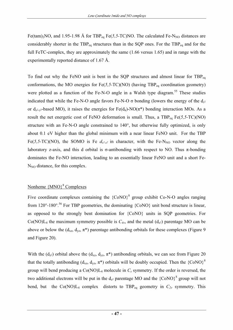
To find out why the FeNO unit is bent in the SQP structures and almost linear for TBPeq
conformations, the MO energies for Fe(5,5-TC)(NO) (having TBPeq coordination geometry)
were plotted as a function of the Fe-N-O angle in a Walsh type diagram.55 These studies
indicated that while the Fe-N-O angle favors Fe-N-O σ bonding (lowers the energy of the dz2
or dx2-z2-based MO), it raises the energies for Fe(dπ)-NO(π*) bonding interaction MOs. As a
result the net energetic cost of FeNO deformation is small. Thus, a TBPeq Fe(5,5-TC)(NO)
structure with an Fe-N-O angle constrained to 140°, but otherwise fully optimized, is only
about 0.1 eV higher than the global minimum with a near linear FeNO unit. For the TBP
Fe(5,5-TC)(NO), the SOMO is Fe dx2-z2 in character, with the Fe-NNO vector along the
laboratory z-axis, and this d orbital is σ-antibonding with respect to NO. Thus π-bonding
dominates the Fe-NO interaction, leading to an essentially linear FeNO unit and a short Fe-
NNO distance, for this complex.
Nonheme {MNO}8 Complexes
Five coordinate complexes containing the {CoNO}8 group exhibit Co-N-O angles ranging
from 120°-180°.56 For TBP geometries, the dominating {CoNO} unit bond structure is linear,
as opposed to the strongly bent domination for {CoNO} units in SQP geometries. For
Co(NO)L4 the maximum symmetry possible is C4v, and the metal (dz2) parentage MO can be
above or below the (dxz, dyz, π*) parentage antibonding orbitals for these complexes (Figure 9
and Figure 20).
With the (dz2) orbital above the (dxz, dyz, π*) antibonding orbitals, we can see from Figure 20
that the totally antibonding (dxz, dyz, π*) orbitals will be doubly occupied. Then the {CoNO}8
group will bend producing a Co(NO)L4 molecule in Cs symmetry. If the order is reversed, the
two additional electrons will be put in the dz2 parentage MO and the {CoNO}8 group will not
bend, but the Co(NO)L4 complex distorts to TBPeq geometry in C2v symmetry. This

Low-Coordinate Imido and NO complexes
- 48 -
distortion makes the dz2 parentage MO less antibonding, by easing the metal dz2 - NO σ*
antibonding interaction, and thereby lowering the energy of the complex. Thus for five
coordinate complexes of the {CoNO}8 group, the choice between a TBP structure of C2v
symmetry and a SQP structure of C4v symmetry is dictated by the relative energies of the dz2 –
and (dxz, dyz, π*) parentage orbitals of the hypothetical C4v linear species.
Figure 20. Arrangement of molecular orbitals in five-coordinate {MNO}n when M-N-O is 180° (left) and 120° (right).
Interestingly, Lippard and coworkers57 reported both a SQP and a TBP geometrical {CoNO}8
with essentially bent MNO units. A [(Co(NO)(TC-3,3)] was claimed to be paramagnetic, had
a SQP coordination geometry and displayed an essentially bent M-N-O bond of 127.3°. A
[(Co(NO)(TC-4,4)] was in contrast claimed to be diamagnetic, had a TBP coordination
geometry and displayed Co-N-O bond angles of 128.9° and 134.9° from X-ray
crystallography.
4-coordinate Terminal Transition Metal Nitrosyls
Only very few 4-coordinate first-row transition metal complexes with a terminal NO ligand
have been reported. An {FeNO}7 complex, [Fe(StBu)3(NO)]−, reported by Harrop et al.58 has
a Fe-NNO distance of 1.711 Å, a N-O distance of 1.168 Å and a Fe-N-O bond angle of 174.2°.
By spectroscopic examinations, this complex is assigned to be an S = 5/2 FeIII ion
antiferromagnetically coupled to an S = 1 NO−, giving an overall S = 2 state. The metal ion
dyz, dzx, π*(NO)
dz2, σ(NO)
dxy
dx2-y2
π*(NO), dyz, dzx
180°
dxy
dyz, π*(NO) dzx, π*(NO)
dz2, π*(NO)
π*(NO), dz2 π*(NO), dyz
dx2-y2
120°
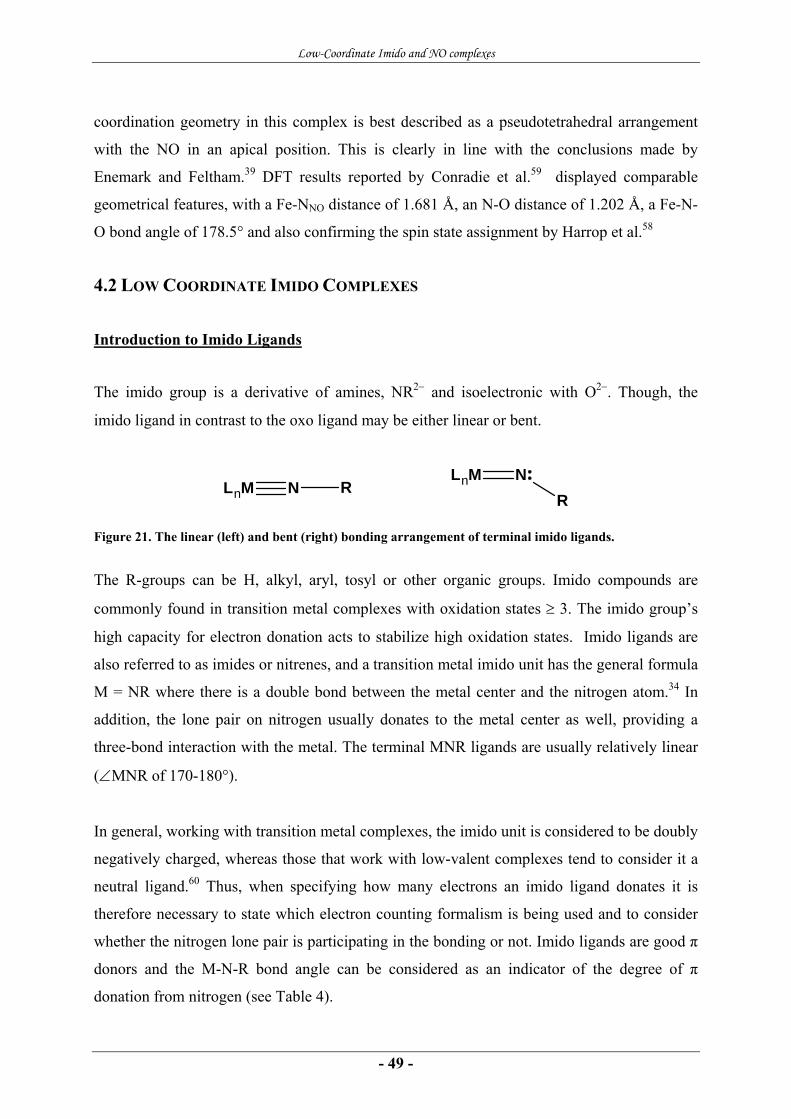
Low-Coordinate Imido and NO complexes
- 49 -
LnM NR
LnM N R
coordination geometry in this complex is best described as a pseudotetrahedral arrangement
with the NO in an apical position. This is clearly in line with the conclusions made by
Enemark and Feltham.39 DFT results reported by Conradie et al.59 displayed comparable
geometrical features, with a Fe-NNO distance of 1.681 Å, an N-O distance of 1.202 Å, a Fe-N-
O bond angle of 178.5° and also confirming the spin state assignment by Harrop et al.58
4.2 LOW COORDINATE IMIDO COMPLEXES
Introduction to Imido Ligands
The imido group is a derivative of amines, NR2− and isoelectronic with O2−. Though, the
imido ligand in contrast to the oxo ligand may be either linear or bent.
Figure 21. The linear (left) and bent (right) bonding arrangement of terminal imido ligands.
The R-groups can be H, alkyl, aryl, tosyl or other organic groups. Imido compounds are
commonly found in transition metal complexes with oxidation states ≥ 3. The imido group’s
high capacity for electron donation acts to stabilize high oxidation states. Imido ligands are
also referred to as imides or nitrenes, and a transition metal imido unit has the general formula
M = NR where there is a double bond between the metal center and the nitrogen atom.34 In
addition, the lone pair on nitrogen usually donates to the metal center as well, providing a
three-bond interaction with the metal. The terminal MNR ligands are usually relatively linear
(∠MNR of 170-180°).
In general, working with transition metal complexes, the imido unit is considered to be doubly
negatively charged, whereas those that work with low-valent complexes tend to consider it a
neutral ligand.60 Thus, when specifying how many electrons an imido ligand donates it is
therefore necessary to state which electron counting formalism is being used and to consider
whether the nitrogen lone pair is participating in the bonding or not. Imido ligands are good π
donors and the M-N-R bond angle can be considered as an indicator of the degree of π
donation from nitrogen (see Table 4).

Low-Coordinate Imido and NO complexes
- 50 -
Table 4. Summarizing the bonding modes of terminal imido ligands. Modified from Toraki.60
Unit geometry Linear metal-imido Bent metal-imido
Hybridization of nitrogen sp sp2 Idealized bond angle 180° 120° Electron donation NR2- 6 e- 4 e- Electron donation neutral 4 e- 2 e-
In general, the only circumstances under which imido ligands are not linear: 60
• If there is no empty d-orbital on the metal that has the proper symmetry to overlap
with the nitrogen lone pair (sp) orbital.
• If the metal electron count is already 18 electrons in which case it will usually have
another imido ligand which is linear.
• If the imido ligand is part of a cyclic or multidentate ligand which physically
constrains it from being linear.
In tending to maintain an 18e- count in electron rich compounds, and depending upon the
nature of the ancillary ligands, bending may occur as required.
Metal-Ligand Multiple Bonds
Transition metal compounds, such as vanadyl oxo-, uranyl oxo- and permanganate- and
osmium tetroxide complexes all display M = O bond distance in the range of 1.59-1.66 Å,
indicating multiple bonding. The π component in these bonds is regarded as arising from oxo
π → metal dπ electron flow. Since this is the opposite of electron flow in π-bonding ligands of
the CO type, it is not surprising that the latter are the more stable in low oxidation states and
the oxo ligands more likely to stabilize high oxidation states. The M = O bonding is typically
affected by the nature of group trans to it, giving the oxo ligand a strong trans influence.
Donors that increase electron density on the metal tend to reduce its acceptor properties, thus
lowering the M-O multiple bond character. Because of the strong trans influence, ligands trans
to oxygen may be labile.34 In contrast to metal-oxo compounds, compounds containing metal-
imido linkages are often better represented by M≡NR,3 and in most cases something in
between a double and a triple bond. There are actually few cases where the presence of a long
M-N bond (≥1.8 Å) and a distinctly non-linear arrangement (∠ M-N-R ≤ 160°) are found. For
most cases, the distances are ~1.7 Å and the angles > 170°, especially when the arrangement
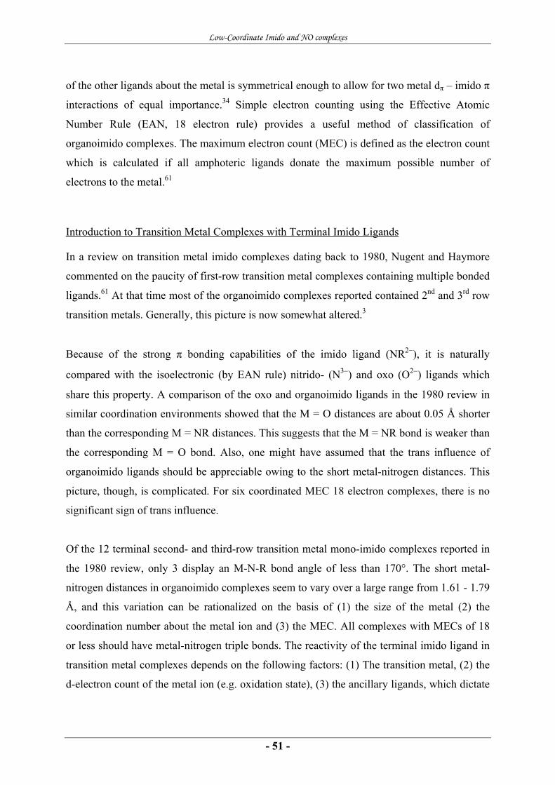
Low-Coordinate Imido and NO complexes
- 51 -
of the other ligands about the metal is symmetrical enough to allow for two metal dπ – imido π
interactions of equal importance.34 Simple electron counting using the Effective Atomic
Number Rule (EAN, 18 electron rule) provides a useful method of classification of
organoimido complexes. The maximum electron count (MEC) is defined as the electron count
which is calculated if all amphoteric ligands donate the maximum possible number of
electrons to the metal.61
Introduction to Transition Metal Complexes with Terminal Imido Ligands
In a review on transition metal imido complexes dating back to 1980, Nugent and Haymore
commented on the paucity of first-row transition metal complexes containing multiple bonded
ligands.61 At that time most of the organoimido complexes reported contained 2nd and 3rd row
transition metals. Generally, this picture is now somewhat altered.3
Because of the strong π bonding capabilities of the imido ligand (NR2−), it is naturally
compared with the isoelectronic (by EAN rule) nitrido- (N3−) and oxo (O2−) ligands which
share this property. A comparison of the oxo and organoimido ligands in the 1980 review in
similar coordination environments showed that the M = O distances are about 0.05 Å shorter
than the corresponding M = NR distances. This suggests that the M = NR bond is weaker than
the corresponding M = O bond. Also, one might have assumed that the trans influence of
organoimido ligands should be appreciable owing to the short metal-nitrogen distances. This
picture, though, is complicated. For six coordinated MEC 18 electron complexes, there is no
significant sign of trans influence.
Of the 12 terminal second- and third-row transition metal mono-imido complexes reported in
the 1980 review, only 3 display an M-N-R bond angle of less than 170°. The short metal-
nitrogen distances in organoimido complexes seem to vary over a large range from 1.61 - 1.79
Å, and this variation can be rationalized on the basis of (1) the size of the metal (2) the
coordination number about the metal ion and (3) the MEC. All complexes with MECs of 18
or less should have metal-nitrogen triple bonds. The reactivity of the terminal imido ligand in
transition metal complexes depends on the following factors: (1) The transition metal, (2) the
d-electron count of the metal ion (e.g. oxidation state), (3) the ancillary ligands, which dictate

Low-Coordinate Imido and NO complexes
- 52 -
the spin state. All factors contribute to the π interaction between the ligand p-orbitals and the
metal d-orbitals. As a simplification of this interaction, one extreme would be when the π*
orbital is mostly metal d in character (case A) and the other when the π* orbital is mostly
ligand p in character (case B). In case A the metal is considered to be electrophilic and hence
a nucleophilic ligand is expected to result. For case B this is reversed, the ligand is predicted
to be electrophilic when the π* orbital is mostly ligand in character. Thus typically expected
for early transition metal complexes is nucleophilic behavior of the ligand in high oxidation
states and for late transition metals is electrophilic behavior in low oxidation states.62
Therefore, as one moves up and to the right in the periodic table for transition metals, the
amount of ligand character to the π* orbital increases and the electrophilicity of the ligand
increases.3
Figure 22. Case A represents a nucleophilic ligand and Case B represents an electrophilic ligand. Adapted from Eikey et al.62
3-coordinate Trigonal-Planar Imido Complexes
Reports on three-coordinate transition metal complexes with terminal imido ligands are sparse
and rather recent. Warren and his group have reported one d6 CoIII-imido63 and one d7 NiIII-
imido64 compound, both displaying a trigonal planar geometry with moderately bent M-N-C
bond angles of 161.5° and 164.5° in the plane of the basal ligands, respectively. For both the
M-NIm distances were in the range of 1.64-1.66 Å.
Additionally reported DFT results for the d6 complex supported the presence of a low-spin
complex stabilized by σ and π donations from the imido ligand to the metal, leading to
Case A Case B
dπ
dπ
pπ
pπ
π* π*
π π
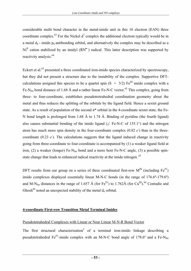
Low-Coordinate Imido and NO complexes
- 53 -
considerable multi bond character in the metal-imido unit in this 16 electron (EAN) three
coordinate complex.63 For the Nickel d7 complex the additional electron typically would be in
a metal dπ - imido pπ antibonding orbital, and alternatively the complex may be described as a
NiII cation stabilized by an imidyl (RN•−) radical. This latter description was supported by
reactivity analysis.64
Eckert et al.65 presented a three coordinated iron-imido species characterized by spectroscopy,
but they did not present a structure due to the instability of the complex. Supportive DFT-
calculations assigned this species to be a quartet spin (S = 3/2) FeIII imido complex with a
Fe-NIm bond distance of 1.68 Å and a rather linear Fe-N-C vector.65 This complex, going from
three- to four-coordinate, establishes pseudotretrahedral coordination geometry about the
metal and thus reduces the splitting of the orbitals by the ligand field. Hence a sextet ground
state. As a result of population of the second π* orbital in the 4-coordinate sextet state, the Fe-
N bond length is prolonged from 1.68 Å to 1.74 Å. Binding of pyridine (the fourth ligand)
also causes substantial bending of the imido ligand (∠ Fe-N-C of 155.1°) and the nitrogen
atom has much more spin density in the four-coordinate complex (0.82 e-) than in the three-
coordinate (0.23 e-). The calculations suggests that the ligand induced change in reactivity
going from three-coordinate to four-coordinate is accompanied by (1) a weaker ligand field at
iron, (2) a weaker (longer) Fe-NIm bond and a more bent Fe-N-C angle, (3) a possible spin-
state change that leads to enhanced radical reactivity at the imido nitrogen. 65
DFT results from our group on a series of three coordinated first-row MIII (including FeIV)
imido complexes displayed essentially linear M-N-C bonds (in the range of 176.6º-179.6º)
and M-NIm distances in the range of 1.657 Å (for FeIV) to 1.762Å (for CuIII).66 Conradie and
Ghosh66 noted an unexpected stability of the metal dσ orbital.
4-coordinate First-row Transition Metal Terminal Imides
Pseudotetrahedral Complexes with Linear or Near Linear M-N-R Bond Vector
The first structural characterization3 of a terminal iron-imido linkage describing a
pseudotetrahedral FeIV-imido complex with an M-N-C bond angle of 178.6º and a Fe-NIm
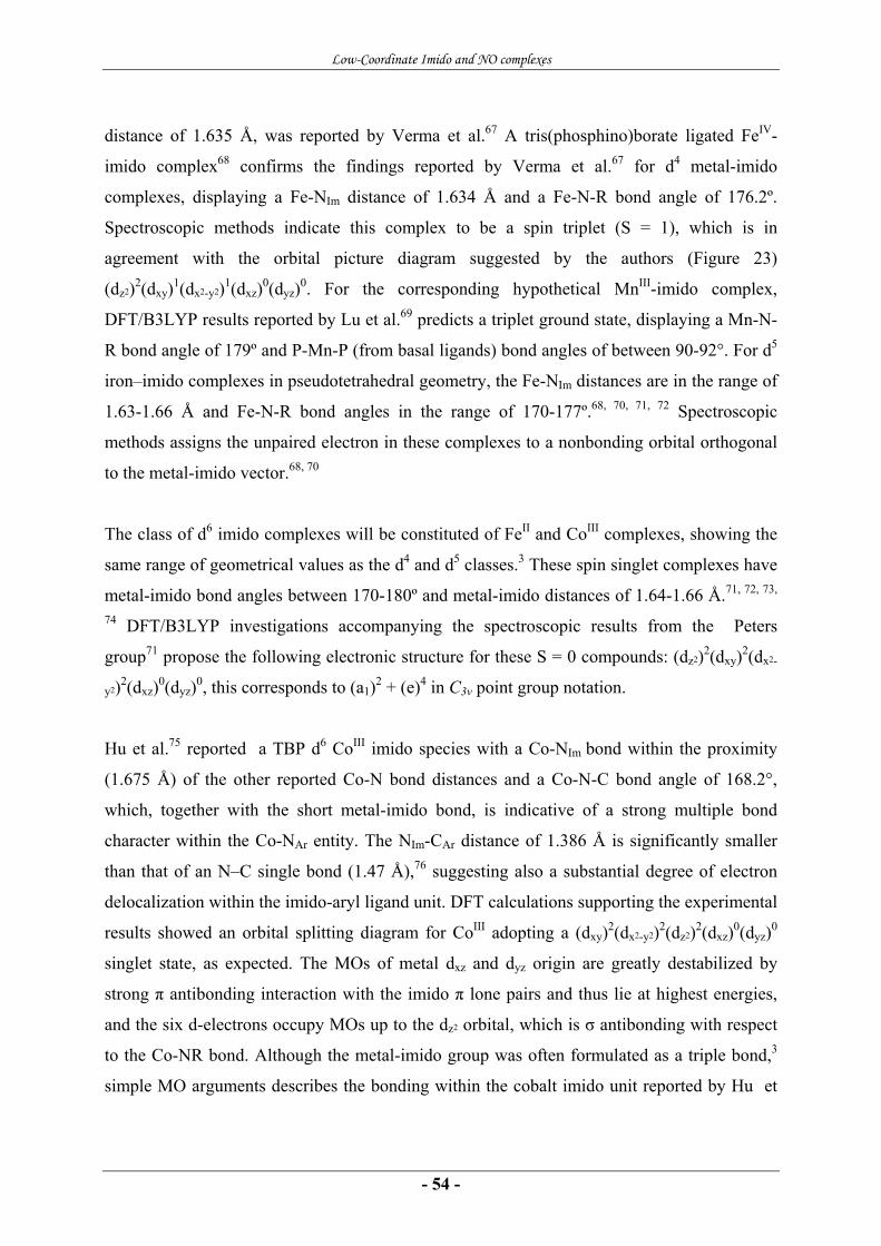
Low-Coordinate Imido and NO complexes
- 54 -
distance of 1.635 Å, was reported by Verma et al.67 A tris(phosphino)borate ligated FeIV-
imido complex68 confirms the findings reported by Verma et al.67 for d4 metal-imido
complexes, displaying a Fe-NIm distance of 1.634 Å and a Fe-N-R bond angle of 176.2º.
Spectroscopic methods indicate this complex to be a spin triplet (S = 1), which is in
agreement with the orbital picture diagram suggested by the authors (Figure 23)
(dz2)2(dxy)1(dx2-y2)1(dxz)0(dyz)0. For the corresponding hypothetical MnIII-imido complex,
DFT/B3LYP results reported by Lu et al.69 predicts a triplet ground state, displaying a Mn-N-
R bond angle of 179º and P-Mn-P (from basal ligands) bond angles of between 90-92°. For d5
iron–imido complexes in pseudotetrahedral geometry, the Fe-NIm distances are in the range of
1.63-1.66 Å and Fe-N-R bond angles in the range of 170-177º.68, 70, 71, 72 Spectroscopic
methods assigns the unpaired electron in these complexes to a nonbonding orbital orthogonal
to the metal-imido vector.68, 70
The class of d6 imido complexes will be constituted of FeII and CoIII complexes, showing the
same range of geometrical values as the d4 and d5 classes.3 These spin singlet complexes have
metal-imido bond angles between 170-180º and metal-imido distances of 1.64-1.66 Å.71, 72, 73,
74 DFT/B3LYP investigations accompanying the spectroscopic results from the Peters
group71 propose the following electronic structure for these S = 0 compounds: (dz2)2(dxy)2(dx2-
y2)2(dxz)0(dyz)0, this corresponds to (a1)2 + (e)4 in C3v point group notation.
Hu et al.75 reported a TBP d6 CoIII imido species with a Co-NIm bond within the proximity
(1.675 Å) of the other reported Co-N bond distances and a Co-N-C bond angle of 168.2°,
which, together with the short metal-imido bond, is indicative of a strong multiple bond
character within the Co-NAr entity. The NIm-CAr distance of 1.386 Å is significantly smaller
than that of an N–C single bond (1.47 Å),76 suggesting also a substantial degree of electron
delocalization within the imido-aryl ligand unit. DFT calculations supporting the experimental
results showed an orbital splitting diagram for CoIII adopting a (dxy)2(dx2-y2)2(dz2)2(dxz)0(dyz)0
singlet state, as expected. The MOs of metal dxz and dyz origin are greatly destabilized by
strong π antibonding interaction with the imido π lone pairs and thus lie at highest energies,
and the six d-electrons occupy MOs up to the dz2 orbital, which is σ antibonding with respect
to the Co-NR bond. Although the metal-imido group was often formulated as a triple bond,3
simple MO arguments describes the bonding within the cobalt imido unit reported by Hu et

Low-Coordinate Imido and NO complexes
- 55 -
al.75 as a formal double bond. When the antibonding metal dz2-imido σ orbital is occupied, the
bond between the metal and the imido group has no σ contribution, thus being a double bond
with only π contribution.
To elaborate the experimental results on metal-imido compounds, Wasbotten and Ghosh
reported a DFT study on three different classes of tripodal supporting ligands, namely the
trisphosphine-, the tris(N-heterocyclic)carbene- and the hydrotris(pyrazolyl)borate class of
ligands.77 Wasbotten and Ghosh found that the tripodal supporting ligand played a significant
role in tuning the spin state energetics for pseudotetrahedral d6 cobalt-imido complexes. This
work also provided theoretical structural data on d3, d4 and d5 transition metal imido
complexes in pseudotetrahedral geometries. The d3 CrIII-imido complex was assigned as S =
3/2 (dδ)1(dδ')1(dσ)1 for both the trisphosphine- (mebp3) and the hydrotris(pyrazolyl)borate (Tp)
class of ligands. For the MnIII (d4) complexes, calculations indicated that the triphosphine
MnIII(NMe) would display an S = 1 ground state while the hydrotrispyrazolyl MnIII(NtBu)
would yield a high-spin S = 2 species. Correspondingly, for the FeIII (d5) complexes
calculations indicated that the FeIII(mebp3)(NMe) would display an S = 1/2 ground state
with a slightly bent Fe-N-R bond vector while the FeIII(TptBu,Me)(NtBu) would yield a high-
spin S = 5/2 species with a perfectly linear Fe-N-R vector. Thus switch between the
hydrotrispyrazolyl and triphosphine basal ligands completely reverse the spin state energetics.
The hydrotrispyrazolyl MIII(NtBu) high-spin species for both Fe and Mn displayed quite long
optimized M-NIm distances (1.778 Å and 1.787 Å, respectively).
As seen above, all experimentally reported d4, d5 and d6 pseudotetrahedrally coordinated
mononuclear, terminal metal-imido compounds display relatively short metal-imido distances
(≤ 1.66Å) and relatively linear metal-imido bond angles (≥ 170º). These observations are
consistent with strong π-interaction between the metal and the imido group. The presence of
two strong π-bonds from the imido linkage together with the strong field executed by the
tris(phosphino)borate ligands affords a low-spin ground state in both FeII and FeIII systems,
despite their low coordinate geometries.3 DFT investigations indicate that these species are
best described by a two over three d-orbital splitting diagram71 in which an orbital of metal dz2
parentage lies at low energy, close to the metal dxy and dx2-y2 parentage orbitals (see Figure
23).
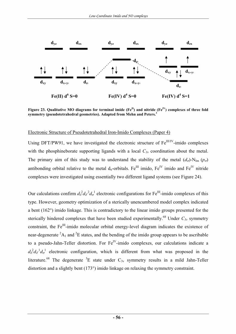
Low-Coordinate Imido and NO complexes
- 56 -
Figure 23. Qualitative MO diagrams for terminal imide (FeII) and nitride (FeIV) complexes of three fold symmetry (pseudotetrahedral geometries). Adapted from Mehn and Peters.3
Electronic Structure of Pseudotetrahedral Iron-Imido Complexes (Paper 4)
Using DFT/PW91, we have investigated the electronic structure of FeIII/IV-imido complexes
with the phosphineborate supporting ligands with a local C3v coordination about the metal.
The primary aim of this study was to understand the stability of the metal (dσ)-NIm (pσ)
antibonding orbital relative to the metal dπ-orbitals. FeIII imido, FeIV imido and FeIV nitride
complexes were investigated using essentially two different ligand systems (see Figure 24).
Our calculations confirm dδ2dδ´
2dσ1 electronic configurations for FeIII-imido complexes of this
type. However, geometry optimization of a sterically unencumbered model complex indicated
a bent (162°) imido linkage. This is contradictory to the linear imido groups presented for the
sterically hindered complexes that have been studied experimentally.68 Under C3v symmetry
constraint, the FeIII-imido molecular orbital energy-level diagram indicates the existence of
near-degenerate 2A1 and 2E states, and the bending of the imido group appears to be ascribable
to a pseudo-Jahn-Teller distortion. For FeIV-imido complexes, our calculations indicate a
dδ2dδ´
1dσ1 electronic configuration, which is different from what was proposed in the
literature.68 The degenerate 3E state under C3v symmetry results in a mild Jahn-Teller
distortion and a slightly bent (173°) imido linkage on relaxing the symmetry constraint.
Fe(II) d6 S=0
dz2
dyz dzx
dx2-y2 dxy
Fe(IV) d4 S=0
dz2
dyz dzx
dx2-y2 dxy
Fe(IV) d4 S=1
dz2
dyz dzx
dx2-y2 dxy
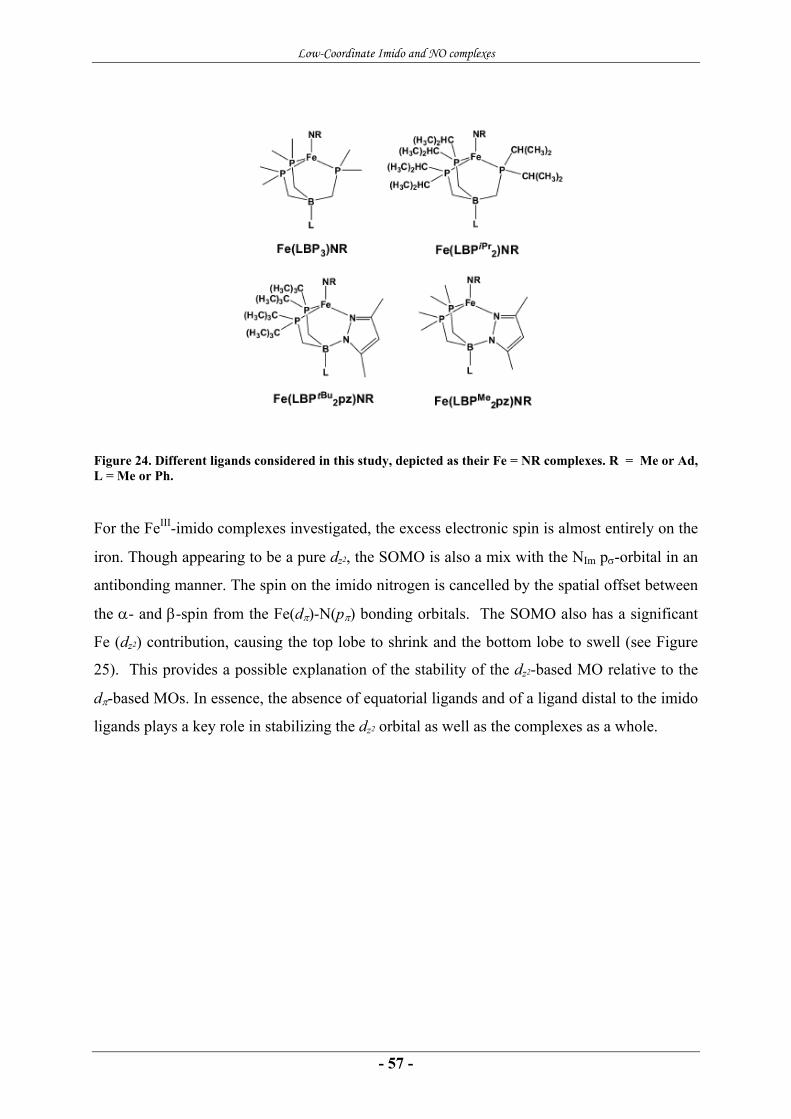
Low-Coordinate Imido and NO complexes
- 57 -
Figure 24. Different ligands considered in this study, depicted as their Fe = NR complexes. R = Me or Ad, L = Me or Ph.
For the FeIII-imido complexes investigated, the excess electronic spin is almost entirely on the
iron. Though appearing to be a pure dz2, the SOMO is also a mix with the NIm pσ-orbital in an
antibonding manner. The spin on the imido nitrogen is cancelled by the spatial offset between
the α- and β-spin from the Fe(dπ)-N(pπ) bonding orbitals. The SOMO also has a significant
Fe (dz2) contribution, causing the top lobe to shrink and the bottom lobe to swell (see Figure
25). This provides a possible explanation of the stability of the dz2-based MO relative to the
dπ-based MOs. In essence, the absence of equatorial ligands and of a ligand distal to the imido
ligands plays a key role in stabilizing the dz2 orbital as well as the complexes as a whole.

Low-Coordinate Imido and NO complexes
- 58 -
Figure 25. The iron-imido complex SOMO (50% Fe d, 12% Fe p, 9% N). Notice the swollen bottom and the shrunken top.
5-coordinate First-row Transition Metal Terminal Imides
All reported 5 coordinate first-row transition metal terminal imido complexes display SQP
coordination geometry, and the first terminal MnV-imido complex was only recently
reported.78 This corrole Mn-imido complex displayed a square pyramidal coordination
geometry with the metal ion 0.5 Å above the average N4 plane, a Mn-NIm distance of 1.613 Å
and a Mn-N-R bond angle of 170.4°. Later reported corrolazine-, the triaza-substituted corrole
analogue, MnV-imido complexes79 displayed essentially the same geometrical key values,
Mn-NIm distances of approximately 1.60 Å and Mn-N-R bond angles of 176.9° and 179.7º.
Both the corrole- and the corrolazine MnV complexes were assigned to be diamagnetic d2
complexes by spectroscopic methods.78, 79 As discussed for the four-coordinate imido TMCs,
the geometrical key values displayed by these complexes are well within the Mn≡NR bond
formalism.79
The only possible exception to this is a TBP coordinated possible d4 intermediate state in the
synthesis of iron amido complexes reported by Borovik and coworkers.80
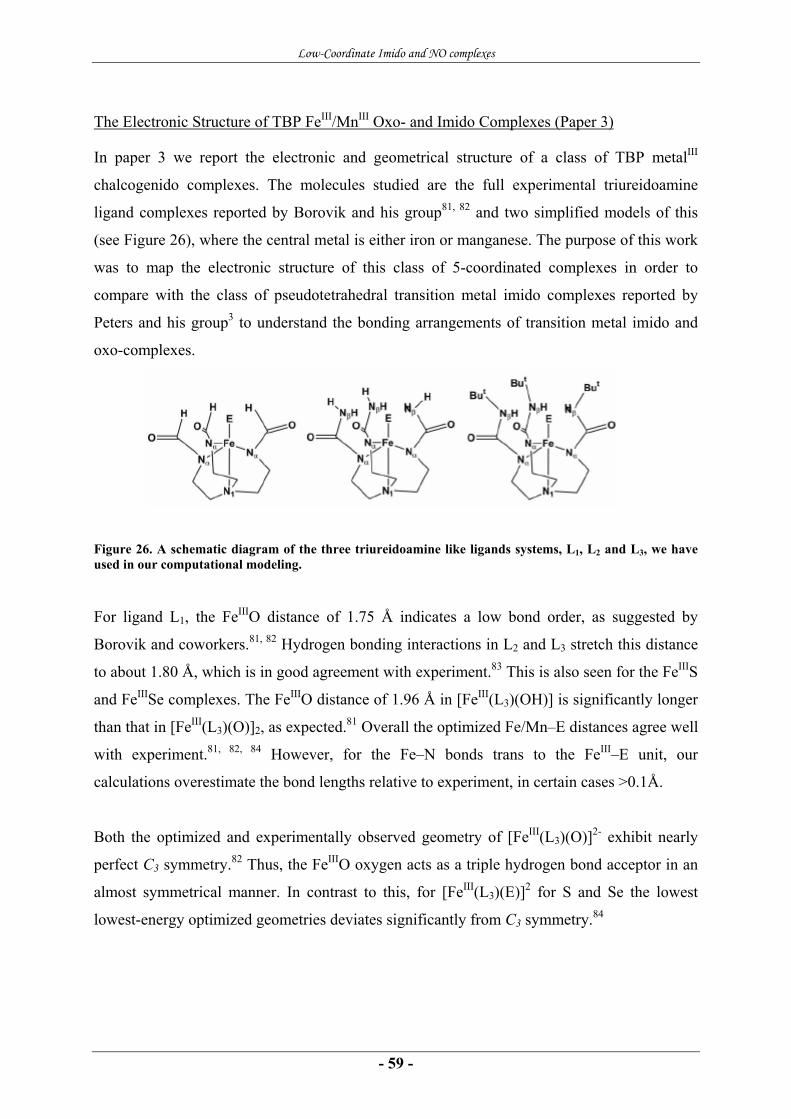
Low-Coordinate Imido and NO complexes
- 59 -
The Electronic Structure of TBP FeIII/MnIII Oxo- and Imido Complexes (Paper 3)
In paper 3 we report the electronic and geometrical structure of a class of TBP metalIII
chalcogenido complexes. The molecules studied are the full experimental triureidoamine
ligand complexes reported by Borovik and his group81, 82 and two simplified models of this
(see Figure 26), where the central metal is either iron or manganese. The purpose of this work
was to map the electronic structure of this class of 5-coordinated complexes in order to
compare with the class of pseudotetrahedral transition metal imido complexes reported by
Peters and his group3 to understand the bonding arrangements of transition metal imido and
oxo-complexes.
Figure 26. A schematic diagram of the three triureidoamine like ligands systems, L1, L2 and L3, we have used in our computational modeling.
For ligand L1, the FeIIIO distance of 1.75 Å indicates a low bond order, as suggested by
Borovik and coworkers.81, 82 Hydrogen bonding interactions in L2 and L3 stretch this distance
to about 1.80 Å, which is in good agreement with experiment.83 This is also seen for the FeIIIS
and FeIIISe complexes. The FeIIIO distance of 1.96 Å in [FeIII(L3)(OH)] is significantly longer
than that in [FeIII(L3)(O)]2, as expected.81 Overall the optimized Fe/Mn–E distances agree well
with experiment.81, 82, 84 However, for the Fe–N bonds trans to the FeIII–E unit, our
calculations overestimate the bond lengths relative to experiment, in certain cases >0.1Å.
Both the optimized and experimentally observed geometry of [FeIII(L3)(O)]2- exhibit nearly
perfect C3 symmetry.82 Thus, the FeIIIO oxygen acts as a triple hydrogen bond acceptor in an
almost symmetrical manner. In contrast to this, for [FeIII(L3)(E)]2 for S and Se the lowest
lowest-energy optimized geometries deviates significantly from C3 symmetry.84
Low-Coordinate Imido and NO complexes
- 60 -
For the simplest species [FeIII(L1)(O)]2, the Fe and O are sharing approximately 94% of the
overall spin (spin populations of 3.9 and 0.8, respectively). For the L2 and L3 complexes, the
oxygen spin is smaller, and the iron ion and equatorial nitrogens must therefore compensate
by carrying larger parts of the overall spin. An observable trend in the spin density profile is,
when going from Mn to Fe, the spin population on the oxygen in the Mn complexes are
dramatically lower than those in analogous Fe species, about 1/3 and 1/10 for the MIII(L3)(O)2-
and the MIII(L3)(OH), respectively.
The orbital splitting diagram for TBP complexes explains easily the high-spin character of the
d4 TBP complexes ([Mn(L3)(O)]2-), but for d5 analogues the situation is slightly more subtle.
Simple CFT arguments here suggest either S = 5/2 or 3/2 but not 1/2. All the Borovik type
complexes are high-spin and this has more to do with their TBP geometries than with the
ligand field strengths of the L3 ligand. For the imido Borovik complexes a wide range of
functionals (from post-SCF calculations) predicts the high-spin FeIII and FeIV cases (S = 5/2
and S = 2) as the ground states. There is a notable difference in bond angle for the Fe-N-C
between the FeIV and the FeIII, the latter being more linear and having a more axially
symmetric spin density profile.
For all the functionals used in this study, the FeIII(L3)-oxo and imido complexes were
indicated as S = 5/2. For [FeIII(L3)(O)]2- the 5/2 state was preferred by between 0.2 - 0.6 eV
over the S = 3/2 state and by 0.6 - 1.3 eV over the S = 1/2 state. The high-spin state was
somewhat less preferred for the FeIV complexes. The calculations reproduce the
experimentally observed high-spin states of these compounds; an analysis based on results
from calculations with different functionals suggests that the high-spin nature of these species
follows largely from their TBP geometry. Iron dπ – oxo pπ interactions invariably result in a
substantial spin density on the oxygen, which in turn may be significantly tuned by hydrogen
bonding interactions. The oxygen spin densities are smaller in analogous manganese-oxo
species, indicating that manganese is less adept at π-bonding than iron.
More on the side of the scope of this thesis, but still of some interest: Using total bonding
energy as taken from the optimized geometry output, we evaluated the H-bond protection of
the FeIIIO unit in the FeIII(L3)(O)2- complex. Computing the adiabatic O-protonation affinities

Low-Coordinate Imido and NO complexes
- 61 -
of [FeIII(L1)(O)]2- and [FeIII(L3)(O)]2- give us a number of 24.5 kcal/mol, which is a rather
large value. Being gas phase numbers, and therefore less of relevance, they still indicate that
the hydrogen bonding interactions may play a major role in stabilizing [FeIII(L3)(O)]2- toward
proton-coupled decomposition.
With their TBP geometry, having two ligands on the z-axis, the hybridization of the metal dz2
based MO, as discussed for the pseudotetradral geometries, is not possible. As expected, we
see no occupation of this orbital for the Borovik type TBP complexes.

Low-Coordinate Imido and NO complexes
- 62 -
Conclusions
- 63 -
5 CONCLUSIONS
In this thesis, computational methods have been used to investigate the electronic and
geometric structures of certain classes of transition metal nitrosyl and imido complexes, with
emphasis on 4- and 5-coordinate geometries.
In Paper 1, we showed, among other things, that the presence of a sixth ligand (ImH) (for
(Por)Fe(NO)(ImH)) pushes much of the spin density away from the Fe onto the NO. The
antibonding metal dz2 - ImH interaction present in the SOMO gives a rather long Fe-NImH
bond. The observed cooperative bending and tilting of the Fe-NNO vector tilted relative to the
porphyrin plane normal, is explained by metal dπ-NO π* and dσ-NO π* orbital interactions.
These findings are not novel but they serve as a useful reference for understanding the less
well-known electronic structures of related nonheme low-coordinate complexes.
In Paper 2, we identified a subtle difference in the nature of the SOMO between SQP and the
TBPeq {FeNO}7 complexes; for the SQP case the SOMO is primarily Fe dz2-based, which
favors σ-bonding interactions with an NO π* orbital, giving a bent FeNO unit. In the TBPeq
case, the SOMO is best described as Fe dx2-y2 based, which stretches out less toward the NO
and is thus less suitable for σ-bonding with NO π* orbital, causing π bonding to dominate and
leading to an essentially linear FeNO unit. For a sterically unhindered model the SQP and
TBPeq stereochemistries are nearly equienergetic, with the former very slightly lower in
energy. Steric constraints such as those operating for Fe(5,5-TC)(NO) can reverse this
stereochemical preference.
In Paper 4, we assigned a dδ2dδ´
2dσ1 electronic configuration to a low-spin FeIII-imido and a
dδ2dδ´
1dσ1 electronic configuration to a FeIV-imido complex with a tripodal phosphine
supporting ligand. The FeIII-imido complex SOMO is essentially an antibonding combination
of the metal dσ orbital and the NIm pσ orbital. However, a significant amount of metal pz
character also mixes in, causing the bottom lobe of the d orbital to swell at the expense of the
Conclusions
- 64 -
top one. This unique feature reduces the antibonding character of these complexes and indeed
is responsible for the very existence and stability of these compounds.
In Paper 3 we assign the high-spin states of iron-chalcogenido complexes to their TBPax
geometries. For the investigated FeIII and FeIV imido complexes, high-spin S = 5/2 and S = 2
states are predicted as ground states for a wide variety of functionals. In contrast to the
pseudotetrahedral complexes reported in Pper 1, the metal dxy and dx2-y2 orbitals in the TBP
complexes do interact strongly with the basal ligand orbitals and are not significantly
stabilized relative to the other d orbitals causing the ligand field splitting to be different in the
two classes of complexes. With two ligands on the z axis, the dz2 orbital enjoys no special
stability, as in the tetrahedral case, and it is perhaps not surprising that no imido complexes
have yet been reported for the ligand in question.
The presented studies reveal striking similarities of the electronic structure for the low-
coordinate transition metal imido- and nitrosyl complexes relative to each other. The
distinction of bent versus linear NO units is attributed to the ranking of the dz2 and dxz/yz
parentage MOs relative to each other. Without a ligand trans to the NO group, the antibonding
metal dz2 - NO σ orbital interaction is lessened by mixing in metal pz, causing the MO to
shrink away from the NO ligand. This exact same orbital interaction appears to be the
explanation of the existence of middle to late first-row transition metal imido complexes, and
is not seen for complexes with axial ligands trans to the imido or nitrosyl unit.

R eferences
- 65 -
R EFERENCES
1 Lippard, S. J.; Berg, J. M. Principles of Bioinorganic Chemistry, 1994, University Science Books, Mill Valley. 2 Walker, F. A. J. Inorg. Biochem. 2005, 99, 216. 3 Mehn, M. P; Peters, J.C. J. Inorg. Biochem. 2006, 100, 634. 4 Enemark, J. H.; Feltham, R. D. Proc. Nat. Acad. Sci. USA, 1972, 69, 3534. 5 Ghosh, A. J. Biol. Inorg. Chem. 2006, 11, 712. 6 Levine, I. N. Quantum Chemistry, 4th ed. 1991, Prentice-Hall Inc, New Jersey. 7 Cramer, C. J. Essentials of Computational Chemistry, 2002, John Wiley & Sons Ltd, Chichester 8 Jensen, F. Introduction to Computational Chemistry, 1999, John Wiley & Sons Ltd, Chichester. 9 Szabo, A.; Ostlund, N. S. Modern Quantum Chemistry, 1996, Dover Publications Inc., Mineola. 10 Ghosh, A; Taylor, P. R. Curr. Opin. Chem. Biol. 2003, 91, 113. 11 Cohen, A. J; Mori-Sánchez, P.; Yang, W. Science, 2008, 321, 792. 12 Atkins, P.; Friedman, R. Molecular Quantum Mechanics, 4th ed., 2005, Oxford University Press Inc., New
York. 13 Koch, W; Holthausen, M. C. A Chemist’s Guide to Density Functional Theory 2nd ed. 2000, Wiley-VCH
Verlag GmbH, Weinheim 14 Hohenberg, P; Kohn, W. Phys. Rev. 1964, 136, B864. 15 Siegbahn, P. E. M.; Blomberg, M. R. A. Chem. Rev. 2000, 100, 421 16 Ghosh, A.; Steene, E. J. Biol. Inorg. Chem. 2001, 6, 739. 17 Ghosh, A; Persson, B. J.; Taylor, P. R. J. Biol. Inorg. Chem. 2003, 8, 507. 18 Ghosh, A.; Gonzalez, E.; Tangen, E.; Roos, B. O. Journal of Physical Chemistry A, 2008, ASAP Article. 19 Neese, F. J. Biol. Inorg. Chem. 2006, 11, 702. 20 Siegbahn, P. E. M. J. Biol. Inorg. Chem. 2006, 11, 695. 21 Boese, A. D.; Martin, J. M. L. J. Chem. Phys. 2003, 119, 3005. 22 Ghosh, A.; Taylor, P. R. J. Chem. Theory Comput. 2005, 1, 597. 23 Baerends, E. J.; Gritsenko, O. V. J. Phys. Chem. A, 1997, 101, 5383. 24 Chong, D. P.; Gritsenko, O. V.; Baerends, E. J. J. Chem. Phys. 2002, 116, 1760. 25 Bartlett, R. J.; Lotrich, V. F.; Schweigert, I. V. J. Phys. Chem. 2005, 123, 062205. 26 (a) te Velde, G.; Bickelhaupt, F.M.; van Gisbergen, S.J.A.; Fonseca Guerra, C.; Baerends, E.J.; Snijders, J.G.;
Ziegler, T. J. Comput. Chem. 2001, 22, 931, (b) Fonseca Guerra, C.; Snijders, J.G.; te Velde, G.; Baerends, E.J.
Theor. Chem. Acc. 1998, 99, 391 (c) ADF2004.01, SCM, Theoretical Chemistry, Vrije Universiteit, Amsterdam,
The Netherlands, http://www.scm.com. 27 http://www.chemcraftprog.com, compliments to mr. Grigoriy A. Zhurko.
R eferences
- 66 -
28 Perdew, J. P.; Chevary, J. A.; Vosko, S. H.; Jackson, K. A.; Pederson, M. R.; Singh, D. J.; Fiolhais, C. Phys.
Rev. B 1991, 46, 6671. 29 Handy, N.C. and A.J. Cohen, Molecular Physics, 2001. 99, 403. 30 Lee, C.; Yang, W.; Parr, R.G., Phys. Rev. B 1988, 37, 785. 31 The ADF reference list: http://www.scm.com/Doc/Doc2007.01/ADF/ADFUsersGuide/page365.html 32 Rayner-Canham, G.; Overton, T. Descriptive Inorganic Chemistry, 3rd ed., 2003, W. H. Freeman and
Company, New York. 33 Sharpe, A. G. Inorganic Chemistry, 1992, Longman Scientific & Technical, Harlow. 34 Cotton, F. A.; Wilkinson, G.; Murillo, C. A.; Bochmann, M. Advanced Inorganic Chemistry, 6th ed., 2004,
John Wiley & Sons Pte. Ltd, Singapore. 35 Owen, S. M.; Brooker, A..T. A Guide to Modern Inorganic Chemistry, 1991, Longman Scientific &
Technical, Harlow. 36 Schriver, D. F.; Atkins, P. W.; Langford, C. H. Inorganic Chemistry, 2nd ed. 1994, Oxford University Press,
Oxford. 37 McCleverty, J. A. Chem. Rev. 2004, 104, 403. 38 Tangen, E. Unpublished results. 39 Enemark, J. H.; Feltham, R. D. Coord. Chem. Rev. 1974, 13, 339. 40 Li, H.; Igarashi, J.; Jamal, J.; Yang, W.; Poulos, T. L. J. Biol. Inorg. Chem. 2006, 11, 753. 41 Fenske, R. F.; DeKock, R. L. Inorg. Chem. 1972, 11, 437 42 Enemark, J. H.; Feltham, R. D. J. Am. Chem. Soc. 1974, 96, 5002 43 Hoffmann, R.; Chen, M. M. L.; Elian, M.; Rossi, A. R.; Mingos, D. M. P. Inorg. Chem. 1974, 13, 2666. 44 Scheidt, W. R.; Ellison, M. K. Acc. Chem. Res. 1999, 32, 350. 45 Ellison, M. K.; Scheidt, W. R. J. Am. Chem. Soc. 1997, 119, 7404. 46 Scheidt, W. R.; Duval, H. F.; Neal, T. J.; Ellison, M. K. J. Am. Chem. Soc. 2000, 122, 4651 47 Ghosh, A.; Wondimagegn, T. J. Am. Chem. Soc, 2000, 122, 8101 48 Wyllie, G. R. A.; Schulz, C. E.; Scheidt, W. R. Inorg. Chem. 2003, 42, 5722 49 Xu, C.; Spiro, T. G. J. Biol. Inorg. Chem. 2008, 13, 613. 50 Franz, K.J.; Lippard, S. J. J. Am. Chem. Soc. 1998, 120, 9034 51 Conradie, J.; Quarless, D. A.; Hsu, H.-F.; Harrop, T. C.; Lippard, S. J.; Koch, S. A.; Ghosh, A. J. Am. Chem.
Soc. 2007, 129, 10446. 52 Franz, K.J.; Lippard, S. J. J. Am. Chem. Soc. 1998, 121, 10504. 53 Conradie, J.; Ghosh, A. J. Inorg. Biochem. 2006, 2069. 54 Patra, A. K.; Rose, M. J.; Olmstead, M. M.; Mascharak, P. K. J. Am. Chem. Soc, 2004, 126, 4780. 55 Walsh, A. D. J. Chem. Soc. 1953, 2266. 56 Enemark, J. H.; Feltham, R. D. J. Am. Chem. Soc. 1974, 96, 5004. 57 Franz, K.; Doerrer, L. H.; Spingler, B.; Lippard, S. J. Inorg. Chem. 2001. 40, 3774. 58 Harrop, T. C.; Song, D.; Lippard, S. J. J. Am. Chem. Soc, 2006, 128, 3528. 59 Conradie, J.; Ghosh, A. J. Inorg. Biochem. 2006, 100, 2069.

R eferences
- 67 -
60 From Rob Torakis Organometallic Hypertextbook: http://www.ilpi.com/organomet/imido.html, downloaded
26.07.08. 61 Nugent, W. A.; Haymore, B. L. Coord. Chem. Rev. 1980, 31, 123. 62 Eikey, R. A.; Abu-Omar, M. M. Coord. Chem. Rev. 2003, 243, 83 and references therein. 63 Dai, X.; Kapoor, P.; Warren, T. H. J. Am. Chem. Soc. 2004, 126, 4798. 64 Kogut, E.; Wiencko, H. L.; Zhang, L.; Cordeau, D. E.; Warren, T. H. J. Am. Chem. Soc. 2005, 127, 11248. 65 Eckert, N. A.; Vaddadi, S.; Stoian, S.; Lachicotte, R. J.; Cundari, T. R.; Holland, P. L. Angew. Chem. Int. Ed.
2006, 45, 6868. 66 Conradie, J.; Ghosh, A. J. Chem. Theory. Comput. 2007, 3, 689. 67 Verma, A. K.; Nazif, T. N.; Achim, C.; Lee, S. C. J. Am. Chem. Soc. 2000, 122, 11013. 68 Thomas, C. M.; Mankad, N. P.; Peters, J. C. J. Am. Chem. Soc. 2006, 128, 4956. 69 Lu, C.; Peters, J. C. Inorg. Chem. 2006, 45, 8597. 70 Brown, S. D.; Betley, T. A.; Peters, J. C. J. Am. Chem. Soc. 2003, 125, 322. 71 Brown, S. D.; Peters, J. C. J. Am. Chem. Soc. 2005, 127, 1913. 72 Mehn, M. P.; Brown, S. D.; Jenkins, D. M.; Peters, J. C.; Que, L. Jr. Inorg. Chem. 2006, 45, 7417. 73 Jenkins, D. M.; Betley, T. A.; Peters, J. C.; J. Am. Chem. Soc. 2002, 124, 11238. 74 Shay, D. T.; Yap, G. P. A.; Zakharov, L. N.; Rheingold, A. L.; Theopold, K. H. Angew. Chem. Int. Ed. 2005,
44, 1508, corrigendum Angew. Chem. Int. Ed. 2006, 45,7870 75 Hu, X.; Meyer, K. J. Am. Chem. Soc. 2004, 126, 16322. 76 Stark, J. G; Wallace, H. G. Chemistry Data Book, 2nd ed. in SI, 1982, John Murray Ltd, London. 77 Wasboten, I. H.; Ghosh, A. Inorg. Chem. 2007, 46, 7890. 78 Eikey, R. A.; Khan, S. I.; Abu-Omar, M. M. Angew. Chem. Int. Ed. 2002, 41, 3591. 79 Goldberg, D. P. Acc. Chem. Res. 2007, 40, 626. 80 Lucas, R. L.; Powell, D. R.; Borovik, A. S. J. Am. Chem. Soc. 2005, 127, 11596. 81 MacBeth, C. E.; Gupta, R.; Mitchell.-Koch, K. R.; Young Jr., V. G.; Lushington, G. H.; Thompson, W. H.;
Hendrich, M. P.; Borovik, A. S. J. Am. Chem. Soc. 2004, 126, 2556. 82 Borovik, A. S. Acc. Chem. Res. 2005, 38, 54. 83 MacBeth, C. E.; Golombek, A. P.; Young Jr., V. G.; Yang, C.; Kuczera, K.; Hendrich, M. P.; Borovik, A. S.
Science 2000, 289, 938. 84 Larsen, P. L.; Gupta, R.; Powell, D. R.; Borovik, A. S. J. Am. Chem. Soc. 2004, 126, 6522.


Paper 1
Toward Modeling H-NOX Domains: A DFT Study of Heme-
NO Complexes as Hydrogen Bond Acceptors.
Tangen, E.; Svadberg, A.; Ghosh, A.
Inorganic Chemistry 2005, 44, 7802-7805.
(NB: Active link)

Paper 2
The Challenge of Being Straight: Explaining the Linearity of a
Low-Spin {FeNO}7 Unit in a Tropocoronand Complex
Tangen, E.; Conradie, J.; Ghosh, A.
Inorganic Chemistry 2005, 44, 8699-8706.
(NB: Active link)
Paper 3
Trigonal bipyramidal iron(III) and manganese(III) oxo, sulfido,
and selenido complexes. An electronic-structural overview.
Conradie, J.; Tangen, E.; Ghosh, A.
Journal of Inorganic Biochemistry 2006, 100, 707-715.
(NB: Active link)
Paper 4
Bonding in Low-Coordinate Environments: Electronic Structure
of Pseudotetrahedral Iron-Imido Complexes.
Tangen, E.; Conradie, J.; Ghosh, A.
J. Chem. Theory Comput. 2007, 3, 448-457.
(NB: Active link)

ISBN 978-82-92461-95-2


![Lectures 13-14 Coordination Complexes Lectures Chemistry ... · Lectures 13-14 Coordination Complexes Lectures Chemistry 1B, Fall 2013 Page 3 13 coordinate covalent bonding [Co(NH3)6]](https://img.dokumen.tips/doc/110x75/5ae9e97c7f8b9a6d4f91570a/lectures-13-14-coordination-complexes-lectures-chemistry-13-14-coordination.jpg)