Embed Size (px)
Citation preview

MICROBIAL CORROSION OF ALUMIl\;ItJM ALLOYS f.'i MINE WATER
Angela Bondonno
A dissertation submitted to the Faculty of Engineering, University of the Witwatersrand,
Johannesburg, in fulfilment of the requirements for the degree of Master of Science in Engineering.
Johannesburg, 1990

DECLARATION
I declare that this dissertation is my own unaided work. It is being submitted for the Degree of
Mastel of Science in Engineering in the University of the Witwatersrand, Johannesburg. It has not
been submitted before for any degree or examination in any other University.
Signed ~
SfI.\ day of !0J 19'70
ii
ABSTRACT
Since aluminium alloys are being considered for more extensive use in the mining industry, their
susceptibility to corro sian in these environments should be determined. Various aluminium alloy
samples, from in situ test rigs on two South African mines, were examined. It was found that their
surfaces were colonised by a variety of microorganisms including sulphate reducing bacteria and
Pseudomonas spp, Pitting and intergranular corrosion Were the main forms of attack.
Immersion and electrochemical tests were car. jed out in mine water under both static and flow
conditions. Aluminium alloys 1070, 5182,6063 and 6261 were exposed to cultures of Desulfovibriodesulfuricans, Pseudomonas aeruginosa and a mixed strain of sulphate reducing bacteria. Conver-
sion coated and anodized samples were tested under flow conditions only.
The presence of sulphate reducing bacteria in mine water presented an aggressive environment for
aluninium alloys leading to pitting at alloying inclusions and intergranular attack. The involvement
of FeS in the corrosion process was established. The alloys exposed to Pseudomonas cultures also
underwent pitting corrosion. Anodizing and conversion coating were effective as temporary rneas-
ures against microbially induced corrosion provided no defect or damage was present. The alloys
were not r, commended for use in mine waters.
iii

ACKNOWLEDGEl'vffiNTS
The assistance of the following people and organizations is gratefully acknowledged»
Prof. F.P.A. Robinson for his supervision and advice.
M. C. Ringas and Mr M. Tullmin for valuable advice and assistance.
Huletts Aluminium for financial assistance and technical input.
Staff of the £.M unit (Wits University) for advice.
Sandra and Robbie for many hours spent printing photos.
University of the Witwatersrand and CSIR for financial assistance.
iv
Table of Contents
1.0 WfRODUCTION ..........................•........................ 1
2.0 LITERATlJRE REVIEW .....•.........•.............................. 32.1 INTRODUCTION................................................ .. :;
2.2 BACTERIA INVOLVED IN MIC •...................................... 3
2.2.1 Sulphate Reducing Bacteria 4
2.2.2 Thiobacillus ............................•........... ,.......... • 5
2.2.3 Bacteria involved in Iron Transformation 'r;
2.2.4 Slime forming bacteria ............................................•. 62.2.5 Other bacteria 6
2.2.6 Fungi 6
2.3 MODES OF GROWTH OF BACTERIA 6
2.4 IDENTIFICATION OF 'VIIC 72.5 MECHANISMS OF MIC 8
2.5.1 Anaerobic corrosion by SRB 8
2.5.2 Aerobic Corrosion ., 11
2.6 INDUSTP.rES AFFECTED BY MIC . . . . . . . . . . . . . .. 13
2.7 METALS AFFECTED BY MIC 14
2.8 MIC OF ALUMINIUM 14
2.9 CORROSION OF ALUMINIUM 14
2.9.1 Oxide layer and corrosion ..........................•............... 14
2.9.2 Effects of alloying 011 corrosion ...........•.......................... 15
2.10 CASES OF MICROBIAL CORROSION OF ALUMINIUM 16
2.10.1 Corrosion iI1fuel/water systems 1;2.10.2 ·-::orrosion in fresh- and seawater environments 17
2.10.3 Corrosion in mine waters 18
2.10.4 Corrosion in other environments ....................•............... 182.11 MAJOR ORGANISMS INVOLVED IN AL CORROSION 19
2.12 MECHANISMS OF MIC OF AL AND AL ALLOYS ................•..... 21
2.12.1 Depletion of natural inhibitors ..........•........................... 21
2.n.2 Production of corrosive compounds 22
2.: 2.3 Creation of oxygen and/or concentration cells 23
2.12.4 Cathodic depolarization 23
2.12.5 Extracellular enzyme activity and metabolism of alloy constituents 23
2.13 MINING CONDITIONS 24
2.13.1 Water distribution 24
2.13.2 Water composition ............•................................. 24. .2.14 fACTORS AFFECTING CORROSIVITY OF WATERS .......•.......•... 2S
Table of Contents v

2.14.1 Oxygen find pH 25
2.14.2 Saturation Index ........•................................... 262.14.3 Aggressive Ions .........................................••...... 26
2.14.4 Temperature and Flow rate 27
2.14.5 Galvanic etfects ...............•.................................. 27
3.0 EXPER!MENTAL PROCEDURE ....................•................. 283.1 MINE SURVEY ....................•........................ "..... 283.1.1 Analytical Techniques 28
3.2 SPECIFICATIONS OF FLOW LOOP 30
3.3 TEST MATERIALS .................................•.............. 33
3.4 BACTERIA USED IN TESTS 343.5 CULTIVATION OF BACTERIA 343.5.1 Sulphate Reducing Medium ..............................•.......... 343.5.2 Mine Water .............•...................................... 343.5.3 Preparation of Bacterial Cultures 35
3.6 ELECTROCHEMICAL TESTS 363.7 Specimen Preparation 363.7.1 Experimental Arrangement 363.7.2 Potentiodynamic Scans 373.7.3 Cyclic Polarization Scans 373.7.4 Tafel Extrapolation :............................. 38
3.8 STATIC IMMERS10N TESTS 383.8.1 Specimen Preparation 383.8.2 Experimental Arrangement •. 383.8.3 Specimen Examination 40
3.8.4 Specimen Cleaning 413.9 FLOW l,OOP IMMERSION TESTS ...............•.................... +13.9.1 Specimen Preparation 413.9.2 Experimental Arrangement 413.9.3 Specimen Evaluation ,......................... 413.9.4 Specimen Cleaning 42
~4.0 RESULTS ..............................•........•................ 434.1 MINE SURVEY RESULTS 434.1.1 Microbial isolation and identification 434.1.2 Examination of corroded surfaces. 52
4.2 IMMERSION TESTS - STATIC 634.2.1 Tests in nutritive medium ................•......................... 694.2.2 Tests inmine water. . ....................• ,....................... 824.2.3 Weight Loss test results. ...............•.............•..... 99
Table of Contents vi

4.3 IMMERSION TESTS - FLOW CONDITIONS 100
4.3.1 Weight loss test results .... . . . . . . . . . . . . . . . . . . . . . . . . . . . . . . . . . . . . . .. 105
4.4 ELECTROCHEMICAL TESTS· STATIC .. , ' 105
4.4.1 Potentiodynamic scans .............................•..•.......... 105
4.4.2 Cyclic polarizanon scans. ...........................•...•.•........ 107
4.4.3 Tafel extrapolation ....•.......................................... 122
4.5 ELECTROCHEMICAL TESTS - FLOW CONDITIONS . . . . . . . . .. 122
4.5.1 Cyclic polarization ...........................................•... 122
5.0 DISCUSSION ....•...•.....•....••.........•...••.....•.........•. 128
5.1 Mine Survey .•....... ...•........................................ 128
5.2 IMMERSION TESTS - STATIC .........•. '.......................... 128
5.2.1 Weight loss results ..... ..........................•.............. 128
5.3 IMMERSION TESTS - FLOW CONDITIONS 130
5.3.1 Weight loss results 130
5.4 SEM OBSERVATIONS '" ...........•............ " 131
5.5 ELECTROCHEMICAL TESTS 132
5.6 RANKING OF AL AU,OYS , 134
6.0 CONCI.USIONS ....•..•.•.•.............................•..•....• 136
7.0 RECOMMENDAT10NS ..................... ,\ " .. " e_" _ .. 137
8.0 REFERENCES .. e· e· CI .. 138
9.0 APPENDICES ...•...............•..............•..•. ,............. 146
Table of Contents vii

List of Illustrations
Figure 1. Schematic representation of the sulphur-cycle, from (4). . ...••.............. 4Figure 2. Oxygen concentration cell, from (9). .............•................... 12Figure 3. Pourbaix diagram for aluminium in water, from (54). 1)
Figure 4. Effects of alloying or. the corrosion resistance of aluminium, 16Figure 5. Simplified key for identifying bacterial genera. 29Figure 6. Simple key for identifying Pseudomonas spp. ..............•........... 29Figure 7. Total immersion coupon holder for flow loop. From (58). . 30Figure 8. Schematic of electrochemical corrosion test section. From (58). 31Figure 9. Schematic of layout of flow loop. From (.58). . 32Figure 10. General view ot flow loop. From (58). . .•............................ 32Figure 11. Corrosion flask with immersion specimens. 39Figure 12. Lid of corrosion flask used in immersion tests showing ports 40Figure 13. Alloy 1200 in the condition as removed from the system. 43Figure 14. Alclad coupons in the condition as removed from the syste+, 44Figure 15. Alloy .5251in the condition as removed from the system. . 44Figure 16. Alloy 6261 in the condition as removed from the system....•.............. 45Figure 17. Possible Cladosporium colonies 46Figure 18. Fungal, mould and yeast colonies on Sabouraud Dextrose agar. . 46Figure 19. Spores of the fungus Altenaria (Mag. 100x). 47Figure 20. Spores of the fungus Curvularia (Mag. 1000x). 47Figure 21. Possible spores of the fungus Cladosporium (Mag. 400 x).. 48Figure 22. Biofilm on A1clad specimen before cleaning. ..................•........ 49Figure 23. Biofllm on alloy 6261 before cleaning. 49Figure 24. Alloy 6261 before cleaning - note individual cells clumped together. 50Figure 25. Arley 6261 with fungal hyphae and corrosion product. 50Figure 26. Biofilm on conversion coated specimen. 51.Figure 27. Tubercle on specimen 6261. 52Figure 28. Alloy 1200 in the acid cleaned condition. 53Figure 29. Alloy 5251 in the acid cleaned condition. . ,....... 53Figure 30. Alclad in the acid cleaned condition. 54Figure 31. View of alloy 6261 after cleaning. ..................•................ 54Figure 32. Pitting attack on Alclad. .................................•....... 55Figure 33. Pitting attack in 5251. ..........•................................ 56Figure 34. Pitting attack in 1200. ................•.......................... 56Figure 35. Intergranular attack in 1200. 57Figure 36. Sulphide precipitates in pits. ...................•................... 57Figure 37. EDAX trace of precipitates in Fig. 36. . ...............•....... ,...... 58Figure 38. Condition of coupons after biofilm removal. 59
List of Illustrations viii

Figure 39. Condition of coupons after biofilm removal. ..................•........ 59
Figure 40. Condition of coupons after biofilm removal. 60
Figure 41. Pitting on the surface of a 6261 specimen. ..............:.............. 60
Figure 42. Pitting inAlcIad specimen. ..............•.......•.... . . . . . . . . .. 61
Figure 43. Pitting and intergranular attack on the conversion coated 61
Figure 44. Intergranular attack on alloy 1200. ....................•.............. 62
Figure 45. Pits in the direction of extrusion lines in alloy 5251. 62
Figure 46. Close up of Fig. 45 showing pits. 63
Figure 47. Condition of coupons on removal from the static immersion tests 64
Figure 48. Condition of coupons on removal from the static immersion tests ....•...... 65
Figure 49. Condition of coupons on removal from Pseudomonas culture 65
Figure 50. Condition of coupons on removal from aerated Pseudomonas medium ...•.... 66
Figure 51. Condition of coupons on removal from deaerated SRB medium 66
Figure 52. Condition of COl)pOnSon removal from D.desulfuricans culture 67
Figure 53. Condition of coupons on removal from the mixed &RB culture 67
Figure 54. Condition of coupons on removal from the Pseudomonas culture 68
Figure 55. Condition of coupons on removal from sterile deaerated mine water 68
Figure 56. Condition of coupons on removal from sterile aerated mine water. 69
Figure 57. Biofilm on alloy 6261 in mixed SRB culture inmedium 70
Figure 58. Alloy 1070 in D.desulfuricans culture in medium 70
Figure 59. Thick biofilm between extrusion lines of alloy 6261 71
Figure 60. Tubercle covered with bacteria 71
Figure 61. Initial colonization by Desulfovibrio on alloy 5182. 72
Figure 62. Later development of a colony of Desulfovibrio cells. 72
Figure 63. Tubercles covered with bacteria on mild steel 73
Figure 64. EDAX trace of FeS patches on alloys. 73
Figure 65. Patches of PeS corrosion product on the surface of 1070 74
Figure 66. Typical EDAX trace of corrosion product. 74
Figure 67. Alloy 5182 in Pseudomonas culture ....................•............ 75
Figure 68. Start of a pit under a tubercle 76
Figure 69. Alloy 6063 after immersion in a mixed SRB culture. . 76
Figure 70. Pitting in mild steel. 77
Figure 71. Pitting in alloy 5182 77
78Figure 72. Pitting and intergranular attack in alloy 6261.
Figure 73. Alloy 6261 in Pseudomonas culture in medium 78
Figure 74. Alloy 1070 in Pseudomonas culture inmedium. . 79
Figure 75. Pitting in alloy 1070 in sterile SRB medium. 80
Figure 76. Pit at nclusion in 5182 in sterile SRB medium. 80
Figure 77. EDAX of intermetallic compounds in 5182 alloy. .•.............•....... 81
Figure 78. Alloy 6261 in sterile SRB medium. ............•..................... 81
Figure 79. Chloride pitting inmild steel in sterile SRB medium. 82
List of Illustrations IX

Figure 80. Alloy 6261 in a culture of mixed SRB in mine water. ........•............ 83
Figure 81. Individual bacterial colonies on 6063 in mixed SRB culture 83
'::"'~~re 83. Biofilm on 3CR12 in mixed SRB culture in mine water.
Figure 82. Tubercle and bacteria on alloy 5182 ,................................ 84
84
85Figure 84. Hollow tubercle on mild steel .
Figure 85. Biofilm on 6063 in Didcsulfuricans culture in mine water. ............•.... 86
Figure 86. Surface of 3CR12 after immersion in D.desulfuricans culture 86
Figure 87. Tubercles on mild stee; in D.desulfuricans culture 87
Figure 88. EDAX of corrosion product on aluminium alloys. 88
Figure 89. Mounds of bacterial growth and corrosion product on 5132 88
Figure 90. EDAX of corrosion r-zoduct, 89
Figure 91. Alloy 5182 in sterile deaerated mine water. . ....................•...... 90
Figure 92. Alloy 6261 in sterile deaerated mine water ...........................•. 90
Figure 93. 'Pitting in alloy 6261 ,.................. 91
Figure 94. Pitting along grain boundaries , .. ,......................... 92
Figure 9'). Alloy 6063:in D.desulfuricans culture in mine water. 92
Figure 96. Alloy 1070 inmixed SRB culture inmine water. 93
Figure 97. Pitting in alloy 6063 inmixed SRB culture in mine water. . 94
Figure 98. Intergranular corrosion of mild steel •................................ 94
Figure 99. Selective corrosion of phases and pitting in 5182 : 95
Figure 100. Pitting at inclusions in alloy 5182 ......................•........... 96
Figure 101. Pitting of alloy 6261 after immersion in Pseudomonas .culture 96
Figure 102. EDAX trace of inclusion in 5182 alloy. 97
Figure 103. Alloy 6063 in Pseudomonas culture in mine water. 97
Figure 104. Selective attack of phases in 1070 98
Figure 105. Alloy 1070 in sterile aerated mine water. . 98
Figure 106. Weight loss results- medium. 99
Figure 107. \leight loss results- mine water. 100
Figure 108. Condition of coupons on removal from sterile flow loop. 101
Figure 109. Condition of coupons on removal from flow loop with bacteria. 101
Figure 110. Alloy 1070 from flow loop with bacteria. 102
Figure Ill. Alloy 5182 from flow loop with bacteria. 103
Figure 112. Alloy 1070 from flow loop with bacteria. 103
Figure 113. EDAX trace of surface deposit on alloy 6261. :......... 104
Figure 114. Pitting under scale deposit in 6261 in flow loop with bacteria. 104
Figure 115. Weight loss results- flow loop ...................................• 105
Figure 116. Schematic representation of a pitting curve. From (93). 107
Figure 117. Pitting curve of 5182. .:........................................ 108
Figure 118. Pitting curve of alloy 6063 > • • • • • • • • • • • • • • • • • • • • • • • • • • • • • •• 109
Figure 119. Pitting curve for 3CR12. ....•................................... llO
Figure 120. r-;tting curve of 6261. ........................•................. 111
List of Illustrations x

Figure 121. Pitting curve in Pseudomona-i culture. .......•...........•.......... 111
Figure 122. Free corrosion potentials: mine water with AS. 113
Figure 123. Free corrosion potentials: mine water with PAS. 113
Figure 124. Free corrosion potentials: medium with AS. .....•................... 114
Figure 125. Free corrosion potentials: medium with FAS. ..........•.....•........ U4
Figure 126. Free corrosion potentials: mine water. ......•....................... 115
Figure 127. Passive ranges: mine water with AS. .............................•. 116
Figure 128. Passive ranges: mine water with FAS. 116
Figure 129. Passive ranges: medium with AS. .............................•... 117
Figure 130. Passive ranges: medium with FAS. . '. . . . . .. 117
Figure 131. Passive ranges: mine water 118
Figure 132. Passive current densities: mine water with AS. .......................• 119
Figure 133. Passive current densities: mine water with FAS. ....•.................. 120
Figure 134: Passive current densities: medium with AS. 120
Figure 135. Passive current densities: medium with FAS. . _ . . . . . . . . . . • . . . . . .. 121
Figure 136. Passive current densities: mine water. . . . . . . . . . . . . . .. 121
Figure 137. Pitting curve of alloy 5182 (3 hrs) 123
Figure 138. Pitting curve of alloy 1070 (3 days) _................. 123
Figure 139. Free corrosion potentials: mine water flow loop (1-3hrs)
140. Free corrosion potentials: mine water flow loop (3 days)
124
125
125
126
126
127
Figure
Figure
Figure
141. Passive ranges: mine water flow loop (1-3 hrs).
142. Passive ranges: mine water flow loop (3 days).
Figure 143. Passive current densities: mine water flow loop (1-3hrs).
Figure 144. Passive current densities: mine water flow loop (:j clays).
List of Illustrations xi

r.o INTRODUCTION
PROBLEM STATEMENT
Aluminium alloys are finding an increasing application for air, drainage, steam and water supply in
the mining industry. These alloys are currently being considered for more extensive use as
constructional materials in this industry. It is therefore imperative that research be undertaken to
determine the susceptibility of such alloys to corrosion in these environments, Preliminary investi-
gations have revealed the presence of microbial growths on aluminium surfaces in mine water. It
is now widely recognized that microbes play an important role in processes leading to corrosion. of
metals, such as iron and stainless steel.
AIMS
This research project was instituted to examine in detail the microbial corrosion of aluminium al-
loys in mine waters in an attempt to identify the organisms involved, the mechanisms of corrosion,
the type of attack incurred, and possible methods of inhibiting microbial growth on the aluminium
surface.
J!lSTIFICATION
Failures due to corrosion have serious economic consequences and hence mining companies are
becoming increasingly aware of the necessity to control and minimize failure of equipment. Use of
corrosion resistant alloys and effective water treatment programmes must be properly assessed ifmaximum benefit is to be obtained. Aluminium has good corrosion resistance due to the stable,
extremely hard and tenacious protective oxide layer which forms on its surface. In addition,
aluminium alloys have the benefit of a high strength to mass ratio.
BRIEF OUTLINE OF THE PROJECT
This was conducted in 2 main phases:
Phase i
A survey of aluminium samples from test rigs on two South African mines and a literature review
were carried out in order to gain knowledge about predominant microbial species.
INTRODUCTION

Phase 2
Small scale laboratory tests in which aluminium alloys were exposed to different static microbial
cultures Were conducted. Tests were also carried out under flow conditions in a recirculating flow
loop system containing a mixed culture of microorganisms. Furthermore, electrochemical tests and
weight loss evaluations were carried out. Corroded surfaces were examined using both optical and
scanning electron microscopy. Analysis of corrosion product was conducted using the attached
EDAX facility. In all tests, controls consisted of sterile medium.
INTRODUCTION 2

2.0 LITERATURE REVIEW
2.1 INTRODUCTION
In the last decade, microbiologically induced corrosion (MIC) • the deterioration of a metal bycorrosion processes which occur either directly or indirectly as a result of the metabolic activitiesof microorganisms - has been recognised as a serious problem. It is not a new phenomenon, how-ever, as corrosion caused by microorganisms was suggested as early as 1891and then clearlydefinedby 1910 (1). Corrosion brought about by microbes is often one of the major reasons for materialdeterioration or failure and is now accepted as a significant contribution to the estimated R4000million losses that corrosion costs South African industry annually (2). The impact of MIC on in-dustry is widespread. Almost all metals and alloys are affected and the process occurs in mostaqueous systems.
There have been numerous review articles on MIC (3 - 9), therefore this reviewwill present a briefoverview of the organisms, mechanisms and case histories pertaining to general MIC. The sectionon MIC of aluminium is, however, more detailed. Mining conditions and factors affecting themare also discussedwith respect to their possible influence on aluminium in these environments.
2.2 BACTERIA INVOLVED IN MIC
The first indications that microorganisms may be involved in metallic corrosion processes appearedin the work of Gaines (10) when he concluded that the corrosion of underground iron and steelstructures was in part due 'to bacterial activity. The iron bacterium, Galllonella was in fact isolatedfrom corrosion products on a buried steel pipe and high concentrations of sulphur and organicmaterial indicating the presence of sulphate reducing bacteria (SRB) were also detected. The im-portance of' SRB to corrosion was established by van Wolzogen Kuhr in 1922. Since these earlyinvestigations were commenced, corrosion of metals due to the action of microorganisms hasemerged as a problem of considerable economic importance (3).
Three genera of bacteria closely associated with MIC are also involved in sulphur transformation.The fundamental part played by microorganisms in the cycling of the biological elements in thebiosphere is, however, widely recognized. The sulphur bacteria, ie. all those that playa major rolein the biological sulphur cycle, have metabolisms which are highly specialized, thus leading themto occupy unusual ecological niches. These organisms affect the economy and environment in adiverse number of ways, principally due to their metabolic activities and the end products theyproduce (11).
Figure 1 is a schematic representation of the S-cycle. In nature, the S atom is passed through var-ious stages of oxidation by water and soil bacteria, which in so doing, obtain energy for growth.Oxidation of elemental sulphur to sulphates 1S performed by a group of aerobic bacteria of the
LITEnATURE HEVIEW 3

genus Thlobadllus. These are also the main organisms concerned with aerobic microbial corrosion.The importaat organisms in anaerobic conditions are the SRB of the genera Desulfovibrio andDesulfotomaadum: They reduce sulphates to hydrogeu sulphide and probably cause most of thecorrosion attributed to microorganisms.
Colo,.d tulf.d.-6.idiring bocterio
Ch.omaHvm .pp.~,pp.
Coiri.t.u 1ulfid.-o.~dilin" bOClc,io
.go,o '00 IF'P.lhiobotrn" •• pp.
!!ilid!r~ 'PP*Moll ",II,d.--
o';dilingbacterio
ACSIMllATOIlY SUlFAT~ REDUCTION
DCI!_uUoyibri:., SPPO.lulfoto",uculum IPP
High .. _pro .. "N.ic.oQ'Qa ..;.mi
..-- .', SO, elemental suit·ur; g--, sulfide; 50.- sulfate; RSH, organiccompounds, mainly sulfur-cr.nla:ning amlno adds.
Figure t. Schematic representation of the sU!'~ll.r-cycle,from (4).
2.2.1 Sulphate Reducing Bacteria
Sul.,hate reducing bacteria are among the most destructive environmental organism" and their in-dustrial impact is widespread (12). The SRll are a taxonomically diverse group that are nonetheless
related in terms of their physiology and ecology. They are obligate anaerobes that use sulphate as
a terminal electron acceptor, reducing it to sulphide, A few species reduce sulphur to sulphide.
Some species ca.'! optimally Use nitrate or fumarate as electron acceptor, while others grow
fermentatively, for example on pyruvate (7). ,
The earliest SRB to be discovered were found in soil- particularly inwet, deoxygenated clayey soils,
though they can remain viable for long periods in the presence of oxygen - and infresh and seawater
(13). Isolates, or putative isolates from crude cultures obtained from such sources were habitually
grown in lactate-sulphate- inorganic salts liquid media under strictly anaerobic conditions. I..is now
certain that many of the early workers did not in. fact have pure SRB cultures but had other
anaerobic contaminating orvf..usms which at that time were difficult to detect.
LITERATURE REVIEW 4

During the early period, the SRB were considered to comprise only two genera - Desulfovibrio and
Desulfotomaculum. The former were nonsporing Gram negative vibrios mostly motile with polar
flagella, while the latter were sroreforming, rod-shaped, Gram positive organisms. The genera
contained only 7 and 5 species respectively, and carbon sources of growth seemed restricted to it few
compounds such as lactate, pyruvate and malate. This picture has now radically altered due to ad-
vances in studies on the nutrition, biochemistry and ecology of the SRB. Nine genera of SRB have
now been recognized and these represent a wide range of habitats, morphologies and physiologies .
Au important feature concerning the role of these organisms in microbial corrosion is the wide
nutritional diversity displayed by the sulphate reducers as a group.
2.2.2 Thiobacillus
Bacteria in this genera are small (0,5-1 by 3 urn) rod-shaped cells which may be motile or non-
motile. Bergey's Manual lists nine species, most of which are aerobic. They derive their energy from
the oxidation primarily of sulphur, thiosulphate, or both to sulphate, thus producing SUlphuric acid
(4).
2,2.3 Bacteria involved in Iron Transformation
Ferrobacillus
A short, motile, rod-shaped cell, deriving its energy by the oxidation of ferrous iron to the ferric
state. These organisms, as well as certain Thiobacilli, are responsible for the leaching process oflow
grade copper and uranium ores, They accelerate the oxidation of pyrite (FeS) to ferric SUlphate and
sulphuric acid, which in tum accelerates the rate of removal of copper or uranium (4).
Gallionclla
These iron bacteria have unique corrosive 'tendencies. They are kidney-shaped cells which secrete
stalks containing ferric hydroxide. They tend to concentrate chlorides with the result that their de-
posits are rich in ferric chlorides. This causes general corrosion of steel. On austenitic stainless steels,
the effect is more catastrophic with rapid subsurface cavities being formed (6).
Sphaerotilus
These organisms oxidize dissolved ferrous iron to insoluble ferric hydrate, which forms a common
sheath for several cells and produces a characteristic star-like filamentous form. Filamentous iron
bacteria are responsible for the common, hollow, hemi-spherical tubercles seen it, water side steel
equipment. They are aerobic and create oxygen depletion under the tubercles. This is corrosive initself but is made even rnore so when it harbours SRB (6).
LITERATURE REVIEW 5

are bound to the biofilm matrix and readily dissociated for use by the component organisms, Nu-trients produced by component organisms also enter the biofilm and micro- colonies of cells capa-ble of primary production of nutrients are often surrounded by heterotrophic organisms that arestimulated by the exudates to grow and produce adjacent microcolonies The death and cell lysisof primary producers often radically stimulates biofilm growth since biofilms tend to trap and re-cycle cellular components. Because of the matrix enclosed mode of growth of biofilm bacteria, asubstantial ion exchange matrix arises between the component cells and the liquid phase of theirenvironment. Additionally, the gel-like state of the predominantly polysaccharide biofilm matrixlimits the access of antibacterial agents to its component bacteria. Therefore biofiLn bacteria aresubstantially protected from surfactants and biocides (16),
2.4 IDENTIFICATION OF MIC
Nearly all confirmed cases of Ml C have been accompanied by characteristic"deposits. These areusually discrete mounds of corrosion product. Bacterial deposits often have a slimy feeling whenfresh and wet, and are generally soft.and easily deformed (6),
Some bacteria can oxidize or reduce metallic ions directly, egoFe2+ can be oxidized to Fe 3+ which
precipitates in a sheath around the cells. These can accumulate as tubercles in pipes. Tuberculationmay develop into a general irregular buildup.
The corrosion generated by bacteria may take distinctive forms as well. Corrosion mediated by SRBon mild stainless steels has several characteristic features. Usually the metal surface is distinctlynodular, the raised area consisting of accumulated corrosion products (eg black PeS). On removal,nodules display a hard, black outer crust and a relatively soft accumulation near the metal. A black
foul smelling liquid (H2 S) may also be present in the nodule. Beneath the corrosion product themetal is clearly pitted, in a localized fashion and the metal within the cavity is shiny (17). SRB at-tack on cast iron typically produces graphitization, while on nickel, high nickel alloys and cupro-nickels, conical pits containing concentric rings or steps are produced.
Iron bacteria deposits are most often some shade of brown and under their hollow tubercles,hemi-spherical or conical pits are usually found. Under irregular tubercles containing slime formers,
corrosion will be similarly irregular (6). Physical identiftcation is usually sufficient evidence, butchemical and microbiological techniques should also be used. For example, acidification of the
black PeS should result in III S evolution. Microscope and cultural examinations of corrosion
product sampled close to the metal should yield large numbers of bacteria (17). Elemental analyses
of deposits can also be useful. High levels of iron, manganese and chlorides usually indicate
Gallionella. High sulphur points to sulphur oxidizers or reducers. High iron could be a clue to ironbacteria (6).
LlTERATURE REVIEW 7

2.2.4 Slime forming bacteria
Pseudomonas
These organisms proliferate in waters and other industrial environments. They are aerobic oxygen
scavengers which secrete large amounts of organic material thereby creating ideal conditions for
harbouring SRB. This seems to be their primary role in causing corrosion (6). They have also been
associated with degradation of lubricating oils and depletion of oil additives, causing emulsification
of the oil and production of organic acids which ate aggressive to bearing metals (8).
2.2.5 Other bacteria
A wide variety of bacteria produce H2 S. Other bacteria, such as nitrate-reducers, produce ammonia.
Organic acids (eg acetic, butyric) are produced by many bacteria ill anaerobic or micro- aerobic
environments. All these may playa part in the corrosive processes.
2.2.6 Fungi
Aircraft integral fuel tanks have been reported to harbour large mats of the hydrocarbon-utilizing
fungus Cladosporium resinae living in the water bottoms under the kerosene. Exfoliation and grain
boundary attack on the aluminium alloys occurred. beneath the fungal mats leading to perforation
and fatigue. This was found to be due to organic acids produced by the fungus as a metabolic by
product (8). .
2.3 MODES OF GROWTH OF BACTERIA
Costerton (14) has examined the mode of growth of bacteria in industrial aquatic systems and found
that they adopt the same mode of $)fowth that is predominant in natural aquatic systems, viz. inthick sessile biofilms. This type of growth develops initially since, due to chemotactic responses, the
bacteria are able to seek out higher concentrations of food sources. Nutrients, especially organic
substances, are generally in short supply in most aquatic enviro iments but surfaces, including
metals, absorb these materials thereby creating areas of relative p .enty where organisms establish
themselves (15). A bacterial cell initiates the process of irreversible +hesion by binding to the sur-
face using exopolysaccharide glycocalyx polymers. Cell division then produces sister cells that are
bound within the glycocalyx matrix, initiating the development of adherent microcolonies. The
eventual production of a continuous biofilm on the colonised surface is a function of cell division
within micro-colonies and new recruitment of bacteria from the planktonic phase.
Initial colonization of metal surfaces is often by slime forming aerobic bacteria. These, by scav-
enging the oxygen in the local environment, create anaerobic zones which can then be colonized
by SRB. Such structured consortia allow for nutrient trapping which occurs when organic nutrients
LITERATURE REVIEW 6
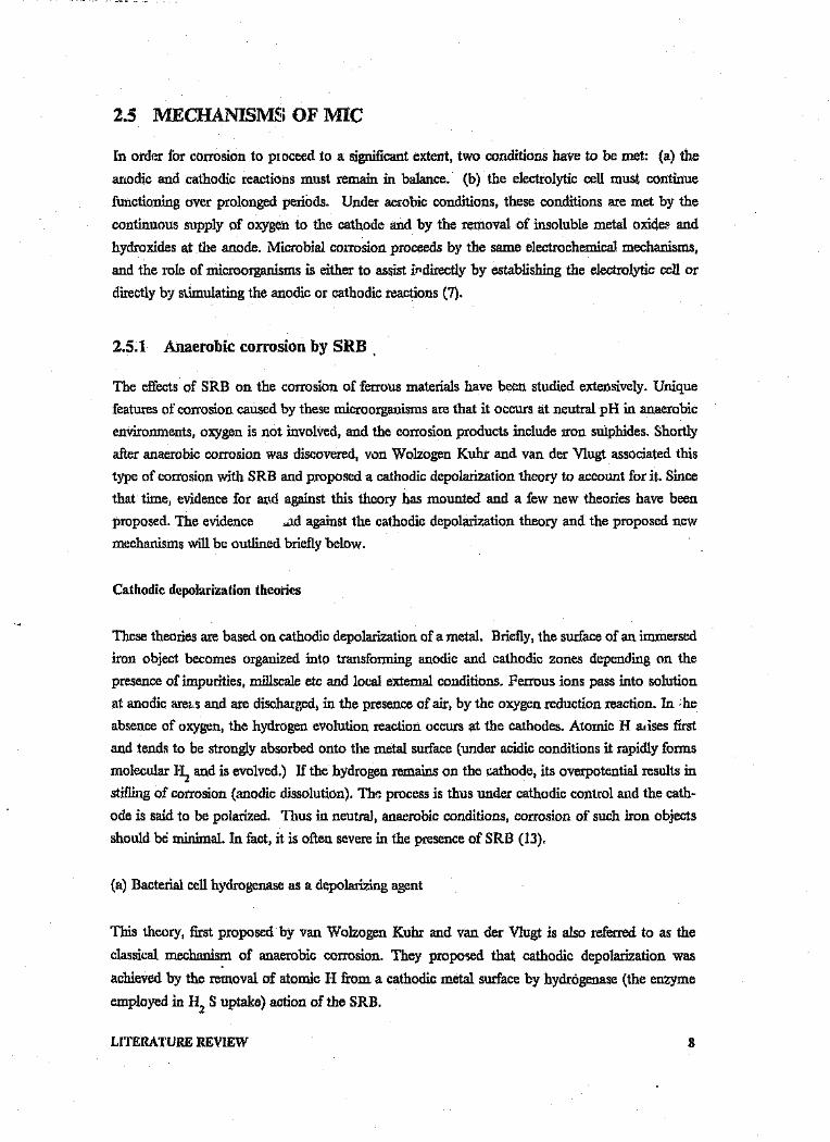
2.5 MECHANISMS OF MIC
In order for corrosion to proceed to a significant extent, two conditions have to be met: (a) the
anodic and cathodic reactions must remain in balance. (b) the electrolytic cell must continue
functioning over prolonged periods. Under aerobic conditions, these conditions are met by the
continuous supply of oxygen to the cathode and by the removal of insoluble metal oxides and
hydroxides at the anode. Microbial corrosion proceeds by the same electrochemical mechanisms,
and the role of microorganisms is either to assist indirectly by establishing the electrolytic cell or
directly by stimulating the anodic or cathodic reactions (7).
2.5.1 Anaerobic corrosion by SRB .
The effects of SRB on the corrosion of ferrous materials have been studied extensively. Unique
features of corrosion caused by these microorganisms are that it occurs at neutral pH in anaerobic
environments, oxygen is not involved, and the corrosion products include iron sulphides. Shortly
after anaerobic corrosion was discovered, von Wolzogen Kuhr and van der V1ugt associated this
type of corrosion with SRB and proposed a cathodic depolarization theory to account for it. Sincethat time, evidence for and against this theory has mounted and a few new theories have been
proposed. The evidence .ad against the cathodic depolarization theory and the proposed new
mechanisms will be outlined briefly below.
Cathodic depolarization theories
These theories are based on cathodic depolarization of a metal. Briefly, the surface of an immersed
iron object becomes organized into transforming anodic and cathodic zones depending on the
presence of impurities, millscale etc and local external conditions. Ferrous ions pass into solution
at anodic ares.s and are discharged, in the presence of air, by the oxygen reduction reaction. In he
absence of oxygen, the hydrogen evolution reaction occurs at the cathodes. Atomic H arises first
and tends to be strongly absorbed onto the metal surface (under acidic conditions it rapidly forms
molecular H2 and is evolved.) If the hydrogen remains on the cathode, its overpotential results in
stifling of corrosion (anodic dissolution). The process is thus under cathodic cont.rol and the cath-
ode is said to be polarized. 'Thus in neutral, anaerobic conditions, corrosion of such iron objects
should be minimal. In fact, it is often severe in the presence of SRB (13),
(a) Bacterial cell hydrogenase as a depolarizing agent
This theory, first proposed by van Wolzogen Kuhr and van der Vlugt is also referred to as the
classical mechanism of anaerobic corrosion. They proposed that cathodic depolarization was
achieved by the removal of atomic H from a cathodic metal surface by hydrogenase (the enzyme
employed in H2 S uptake) action of the SRB.
LITERATURE REVIEW 8
The overall mechanism can be described as follows:
Anodic reaction: 4Ft.! -- > 4Fe2+ + Be '
Dissociation of water: 8R20 --> 8H + + 80H-
Cathodic reaction: 8e- + 8H + -~> tsH
Cathodic depolarization: SO 2- + 8H -- > S 2- + 4H 04 2
Corrosion products: Fe2+ + S 2- --> FeS
3Fe2+ + 60H - --> 3Fe(OH) 2
Overall reaction: 4Fe + S042- + 4H 20 --> 3Fe (OH)2 + FeS + 20R-
Most of the literature on microbial corrosion has been concerned with evidence for and against this
theory. Data in support of the classical theory was obtained by Iverson (in 7) and Booth and Tiller
(in 7). Both studies employed benzyl viologen as terminal oxidant, thus obviating any potential
complication from the production of sulphide. A direct relationship was found between the
hydrogenase activity, the cathodic depolarization activity (as measured by polarization and
potcntiostatic techniques) and the weight loss of mild steel coupons. These studies were carried out
using batch cultures of SRB (7, 18).
(b) Iron sulphide as a depolarizer
In later work, however, using semi-continuous and continuous cultures in sulphate medium, Booth
et al (19) ft und that corrosion rates were generally low and a thin ferrous sulphide film form. don
the test pieces. After a few months, however, this film fractured, with a considerable increase in
corrosion rate. Under these conditions there was little difference between hydrogenase- positive anc
-negative strains as concerned weight loss. In the presence of higher iron concentration, the corro-
sion product was in the form of a bulky black precipitate rather than as an adherent film, and with
both hydropenase-positive and -negative strains high corrosion rates were found (19, Booth et al
in 7). Mara and Williams (20) reached the same general conclusions and suggested that filmbreakdown in low-iron media resulted from sulphidation of the primary corrosion product
mackinawite (FeS1_X ) to greigite (Fe3 S 4 ). Whereas the initial low rate of corrosion was related to
bacterial growt 1. rates, after film rupture corrosion was independent of growth rate. The high rates
of corrosion thus seemed dependant on ferrous sulphide corrosion product, being influencer. too
by its physical and chemical form. The iron sulphide was believed to be acting as a cathode with
the cathodic reaction involving either the evolution of molecular hydrogen or the entry of atomic
hydrogen into the metal or into the defect structure of the sulphide film.
LITERATURE REVIEW 9

The quantitative importance of cathodic depolarization by solid ferrous sulphide was confirmed
(21) when chemically prepared FeS was added to mild steel coupons in a culture of Desulfovibriodesulfuricans in medium containing no sulphate. The extent of corrosion was proportional to the
amount of FeS added and dependant on its direct contact with the metal surface (7).
(c) Iron sulphide and bacterial hydrogenase as depolarizers
Several workers (13,22) focused their attention on the iron sulphides of which there are several-
all semiconductors. It was found in laboratory cultures that a sulphur-deficient sulphide,
mackinawite, arose first; this formed a temporary protective film on the iron surface. As bacterial
growth produced more sulphide ions, the film took these up to form stoichiometric FeS and grad-
ually greigite (Fe3 S 4 ) causing it to thicken and eventually lift, thus exposing base metal. Thereafter
metal dissolution was never suppressed by further film formation. Further work suggested that all
iron SUlphides are cathodic towards iron. The role of SRB in this system could be ei" c to "re-
generate" (or depolarize) the FeS, through hydrogenase activity, thus enabling it to remain cathodic,
or to produce "fresh" iron SUlphide by their growth reaction.
td) Hydrogen sulphide as depolarizer
In contrast to the above postulated mechanisms, Costello (in 7) proposed that cathodic
depolarization activity of the SRB was due to the cathodic activity of the 1-12 S produced by these
organisms. Hydrogenase may play an important secondary role by removing molecular H with the
further generation of more H;1S. Also in agreement with other hypotheses, FeS has been reported
to act as a cathode.
Corrosive metabolite theory
Iverson (in 7) reported that extensive corrosion of iron had been found using spent culture media
from which SRB and sulphide had been removed. The culture filtrates formed a black film on steel
coupons after 3 days. This film Was rich in iron and phosphorus and on acidification, phosphine
was evolved. Iron phosphides have been identified among the corrosion products, but the corrosive
metabolite itself has still not been characterized further than as a volatile phosphorous compound.
The extent of corrosion in any case is considered to result from the effective competition between
the action of sulphide (protective [11m formation) and that of the phosphorus metabolite (corro-
sion).
Weimer et al (23) studied the effect of phosphate on the corrosion of carbon steel and on the
composition of corrosion products in two-stage continuous cultures of Desulfovlbno desulfuricans.It was found that an increase in the phosphate content of the growth medium resulted in an in-
creased corrosion rate of the steel. In addition, analysis of corrosion product revealed that the P
content of the product increased dramatically with increasing phosphate concentration in the me-
LITERATURE REVIEW 10

dium. Chemical analyses indicated that the P was present both as phosphate and an unidentified
component, possibly a reduced P species. An explanation to account for the enhanced corrosion
by phosphate, was offered as being due to the direct electrochemical effect of P-cortaining corrosion
product stimulating cathodic depolarization. Chemical analyses also indicated that sulphur was
present in the corrosion product almost exclusively in the form of sulphides. The importance of
sulphides on corrosion was acknowledged and the suggestion made that. ferrous sulphides were re-
sponsible for the growth of the corrosion product, but that subsequent reactions might alter the
composition and structure of these products.
The sulphur theory
Schaschl (24) e .amined the corrosive action of SUlphur under anaerobic conditions, and found that
its solubility was influenced by sulphide, pH and temperature, and that only dissolved sulphur could
act as a corrodant. He proposed that the corr-ision occurred by a concentration cell met ;'.anism
analagous to an oxygen concentration cell under conditions of differential aeration, with the prin-
cipal role of the bacteria being to promote the concentration cell action by shielding the underlying
metal (anode) from the higher concentrations of dissolved sulphur in the surrounding medium.
Bates (25) has reinterpreted the action of sulphur, proposing that polysulfides (S 2- ) are thex
cathodic reactants. Since microbial corrosion is the result of a community of organisms, certain
species of bacteria can produce elemental sulphur during their metabolic processes. This sulphur
can then act as a cathodic depolarizer as mentioned previously.
It has also been suggested (Maklonado-Zagal in 7) that the high local acidity generated in particles
of solid sulphur reacting with water could be responsible for the high corrosion rates of iron and
steel.
2.5.2 Aerobic Corrosion
Corrosion t-y concentration cell formation
A large number of microbial species, generally aerobic, can cause biofouling of metal and other
surfaces in damp or wet environments. Such biofilms usually contain several species of organism
and the greater part of the mass of the biofilm generally consists of extracellular r-oiymeric material.
Absorption of oxygen and other nutrients by such microbial growths .ause concentration cells to
be set up between the interior of the growth and the immedia.e environment. In such an
electrochemical cell, the oxygen-depleted zone beneath the coherent biofilm is anodic with respect
to the exposed metal bordering the growth and anodic disso ution occurs. Fig. 2 shows
diagramatically the mechanism of anode formation by a differenti. J aeration cell set up under a
microbial colony. Active growth of the organisms keeps the oxyge J. concentration near to zero in
LITERATURE REVIEW 11

the centre, but once the electrochemical cell is established and the colony increases in bulk, ",'~nthe death of organisms in the interior of the colony need not destroy the cell since there is now a.substantial mechanical barrier to the ingress of oxygen. A serious additional problem arises if theanaerobic conditions at the centre of the colony initiate growth of any SRB that became entrappedin the colony in the early stages of growth (26).
Iron bacteria, such as Galllonella and Sphaerotilus are commonly associated wah tubercle formationand corrosion of water distribution pipelines. The raised hard deposits (mainly ferric hydroxide)formed by the action of these bacteria acts in the same way as bacterial biofilms ie corrosion resultsfrom oxygen concentration cells, with the added possibility of the presence of SRB ,(7).
The most important inorganic acid producing organisms are species of Thiobacillus and
Ferrobadllus which are both capable of producing SUlphuricacid. T. thiooxidans, T. thioparus and -.
T. concretivorus are capable of oxidizing sulphur via sulphite, thiosulphate and tetrathionate to free
sulphuric acid, thereby leading to lowered pH values and removal of protective films from metal
surfaces.
TUBERCLE
4Fe
F:gure i. Oxygen concentratiOli cell, from (9). J,"-----Corrosion due to products of bacterial activity
Products of bacterial metabolism which can cause corrosion are mainly organic and inorganic ~cids.
Other products, particularly organic sulphur compounds, may be corrosive in some situations.
LITERATURE REVIEW 12

Ferrobacillus ferrooxidans oxidizes ferrous ions to the ferric form. The ferric salts thus produced
uxidize reduced sulphur compounds to sulphuric acid. In nature the organism is often associated
with the oxidation of pyritic deposits. Acid waters thus produced in mines have been shown to be
corrosive to pumping machinery (3).
Cases of corrosion of iron, copper and Al due to organic acids associated with mould growth have
been reported (3 ). The fungus Cladosporium resinae has frequently been associated with corro sian
of AI fuel tanks, particularly in aircraft. This phenomenon has been attributed to the action of or-
ganic acids secreted by the organism (27).
2.6 INDlJSTRIES AFFECTED BYMIC
Considerable progress in understanding the mechanisms involved in and improved techniques for
detecting MIC over the past two decades has led to an increased awareness of this type of corrosion.
This is especially true in South Africa where the recent droughts, limited water resources and :~-
creasing limitations on effluent discharge to the environment have resulted in increased recycling
and re-use of water. Concurrent to this, industries have noted an increase in microbial corrosion
with MIC often becoming one of the major reasons for material deterioration/failure (2).
Corrosion induced by bacteria is a widely recognized phenomenon in the oil and gas industries
bringing about corrosion of pipelines and machinery, reduction in the value of oil and gas by raising
the sulphide content and by producing toxic H2 S (11, 28-31).
The pulp and paper industry continuously copes with corrosive bacteria in their processes leading
to corrosion of machinery and blackening of paper pulp (11, 32).
III the metal working industry, there have beer numerous cases of microbial contamination of
emulsions lubricants and coolants used in machinery, wire drawing, rolling and deep drawing op-
erations. The results were serious corrosion of drawing dies, wire and sheet products and staining
or alteration of surface finish (33). MIC problems are also found in cooling water systems (32, 34,
35), heat exchangers (34, 36) and condensers (37).
The anaerobic corrosion of buried pipelines by SRB is one of the best known economic activities
of this group. Conditions for growth of bacteria are ideal in the soil/pipe environment (11,38).
Other industries (2) in which corrosion has been attributed to MIC include:
breweries
chemical manufacturing
mining
petroleum
waste water treatment
marine.
LITERATURE REViEW 13

2.7 METALS AFFECTED BY MIC
Almost all engineering materials can be damaged by the effects of the activity of some microbial
groups. There are many citings in the literature of the susceptibility of mild steel and iron to MIC
especially to SRB attack (15, 19, 39-41). Stainless steels are also susceptible to damage, (mainly
pitting) especially in anaerobic environments (32, 36, 37, 42). Damage by bacteria to copper and
nickel (43-46) and to high Ni alloys in natural waters (42) has also been reported. In the 1950's
and 60's microbial deposits in A1 alloy fuel tanks on jet aircraft plugged fuel lines and perforated
the tanks and structural members ~47). Any material immersed in Sea water is v~ry susceptible to
MIC. The surface is likely to be colonized by a wide range of organisms both macro- and micro-
scopic leading to severe corrosion beneath the fouling layer (46,48-53).
2.8 MIC OF ALUMINIUM
In this section, the results of research on the Ml(.. ,)f aluminium and its alloys reported, in various
environments, are surveyed in an attempt to establish: (i) factors affecting microbial corrosion
en) predominant organisms involved in corrosion (iii) mechanisms of microbial corrosic u,
Particular attention is then paid to the mining industry and factors that could affect aluminium
corrosion in this environment.
2.9 CORROSION OF ALUMINIUl\1
2.9.1 Oxide layer and corrosion
Aluminium is an active metal and oxidizes rapidly when exposed to water or air. This results in a
thin, continuous film of oxide on the metal surface which generally protects the metal from further
attack in mildly aggressive environments. The corrosion resistance of aluminium depends on the
stability and continuity of this film or passive layer. If the film becomes damaged locally under
conditions which do not allow for repassivation, localized corrosion in the form of pitting or
inter-granular attack takes place (54). Fig. 3 is a Pourbaix diagram for aluminium ii~water illus-
trating the potential and pH range of aluminium oxide stability and corrosion. The range of oxide
stability cove: j the range of water stability from a pH of about 4,5 to 9 which encompasses most
natural waters. The stability and continuity of the protective film is affected by aggressive ions,
complexing agents, local shifts in pH and crevices (54).
LITERATURE REVIEW 14

2.5,------.,.,----,r--------,
-_---_1.5
2.0 AL(OH):
-2.5 i' , iii Iii i I4 ~ 0 1 234 567 6 9 m n tt u " ~ ~
pH
1.0

A.A. 4 DIGITCODES 7111
1
I I
CORROSION
,,I, .
I I
~I :
~U'I 'I ~r. :• 4~.,I 0-&
CHEMICAL CODES~~----.l---___,_..r.._-L-,-j
AI A1·Mn AI·Mg AI·Mg·Si A'·Zn·Mg AI·Cu· AI.ln.Mg·Sl Mg'Cu
--v--" ----....---.~MEDIUM MEDIUM· HIGH HIGHSTRENGTH SOFT LOW
Figure 4. Effects of alloying on the corrosion resistance of aluminium, from (57).
The electrochemical potexfial of secondary phases or precipitates relative to a'·tminium is of greatimportance. Iron and silicon in commercially pure aluminium form constituents that are cathodicto aluminium. Since they form cathodic points over which the film is weak, they may promoteelectrolytic action in the surrounding aluminium.
High strength Al-Cu alloys have poor corrosion resistance and the amount of copper in the alloyhas a strong influence on its electrode potential. AI and Mn form compounds having almost the. .same electrode potential as the aluminium itself and thus these alloys have good cor rosion resist-
ance. Al-Si alloys have good corrosion resistance since silicon in solid solution has a min~r influ-ence on the electrode potential of aluminii.-a. Silicon particles within the alloy promote galvxaiccorrosion. Mg is an important alloying element for aluminium and the solid solution formed is
anodic to aluminium. Al-Mg alloys are as corrosion resistant as commercially pure aluminium, and-ven mere resistant in sal. .vater and some alkaline solutions. The Al-Mg-Si alloys often have a very
similar electrode potential to pure aluminium as the silicon makes the solid solution mon cathodicand i.., the ratio 2Mg:IS!, this balances out the anodic effect of the Mg (58).
2.10 CASES OF MICROBIAL CORROSION OF ALUMINIUM
Aluminium and its alloys find microbial enemies in many places: in airplane parts, jet fuel lines
and fuel storage tanks, tap and seawater; in natural and artificial media; in aerobic and anaerobic
LITERATURE REVIEW 16

environments. With the increased Use of AI as a prime fabrication material, the problem of its cor-
rosion has come to the forefront in certain engineering applications (59).
2.10.1 Corrosion in fuel/water systems
The aircraft industry, both military and commercial, was first faced with the acute problem of
contaminated fuel in jet aircraft in early 1960. This contamination led to corrosion of Al-alloy fuel
tanks in both aerobic (airplane fuel tanks) and anaerobic (stationary storage tanks) systems. Cor-
rosion occurred in the water-phase of fuel-water mixtures and was most common on the bottom
of tanks and at the fuel-water interface. The contaminants, viz water, particulate matter, surfactants
and microorganisms formed thick slime growths on the bottom and sides of fuel tanks and caused
plugging of fuel filters, malfunction of fuel probes and on one occasion, flame out of an engine (60).
Under these slimes, degradation of the topcoating material and pitting corrosion of AI wing tanks
as a result of microbial activity took place. Areas of. exfoliation of the alloy were reported as other
manifestations of microbial activity. Apart from the direct financial losses, contamination of fuel
tanks can affect the structural integrity and performance of the aircraft. The aircraft industry has
taken steps to provide more corrosion resistant alloys in an attempt to provide tanks which are re-
sistant to the environment being handled. Many expensive changes have been made to counter the
threat of catastrophic deterioration of aircraft structure by contaminants (61). These include rede-
signing susceptible components, changing fabrication techniques, use of biocidal polyurethane fuel
tank lining and stricter fuel filtering and handling procedures.
2.10.2 Corrosion in fresh- and seawater environments
Fouling of metal surfaces in contact with sea and fresh water is the main cause of ceveral technical
problems and economic loss affecting various industrial environments such as cooling water sys-
tems. Microbially induced pitting corrosion was experienced on a finned Al-alloy heat exchang v,
and aluminium screens exposed to ordinary potable water. Since no corrosion inhibitor or rnic.obial
control treatment was implemented, a slime deposit formed on the metal, thereby setting up a dif-
ferential aeration cell (62).
In another case, various metal surfaces (amongst them AI) were exposed tv polluted harbour sea
water used to supply a heat exchanger system of ~ thermal power plant. The presence of fouling
adversely affected heat transfer, increased frictional resistance in the tubes, and of course increased
the overall cost of operating the system (63).
Guillame et al (64) studied conditions of corrosion and immunity of Al in bacterial cultures in fresh
and sea water. Pitting corrosion OCCUltedwhen the bacteria died, or when their metabolism was
disturbed by decomposition of the nutrient medium, or by the presence of A13+ ions. The action
of various Bacillus cultures and a natural living rnicroflora of sea water on Al were examined in sea
water by Ulanovskii et al (65). Pitting corrosion was thought to be due to adsorption of proteolytic
LITERATURE REVIEW 17

bacteria to AI creating alkaline conditions. Willingham and Quinby (66) found that pitting of Al
took place in the presence of cultures of SRB in sea water,
2.10.3 Corrosion in mine waters
A project was initiated in order to assess the corrosion performance of A1 alloys in the inlet
evaporator water circuit at a refrigeration plant in the President Steyn Gold Mine (67). Preliminary
1 isults showed that, on removal from the system, yellow-brown tubercular growths had formed on
the surfaces of the coupons. On removal of these tubercles an interlinking network of deep pits
became evident. The remainder of the coupon was covered with a thin black adherent layer under
which the metal remained unattacked. The relationship between these tubercles and pitting has not
been positively ascertained. There is, however, some evidence to suggest that the corrosion may
have been due to microbial action. Bacteria were found to be present in tubercles produced in the
laboratory under similar conditions. The tubercles consisted mainly of Al oxide/hydroxide together
with a certain amount of SUlphate and silicate. Since very little chloride was detected by both SEMand microprobe analysis, it can only be concluded that the pitting had not been produced by this
ion.
2.10.4 Corrosion in other environments
Since AI and its alloys are finding an increasing application for cable sheathings, pipelines and other
structures buried in soil, the behaviour of these metals in soils is of considerable interest (Reine et
al in 68). Tiller and Booth (68) conducted tests all AI in Butlin medium inoculated with four dif-
ferent SRB, while Brown and. coworkers (in 54) tested various Al alloys in different bacterial cul-
tures in organic medium. In both cases, corrosion of all samples Was reported to have been
accelerated by the presence of bacteria or fungi.
LITERATURE REVIEW 18

2.11 MAJOR ORGANIS~v1SINVOLVED IN AL CORROSION
Medium Microorganisms Type of AI Type or corrosion Ref
Bushnell- Piaeruginosa 7158-1'651 pitting inter- 69Haas(B-H) D .desulfuricans granularfuel; Cresinae blisteringdeionized A .niger exfoliationwater-fuel;B-H cystine;seawaterrned-fuel
deionized Pseudomonas sp. 2024-1'351 70water; 7075-1'651deionized I
water +Triton Xsurfactant +Fe °2 3+ fuel
deionized Piaeruginosa 7178-1'651 pitting 27,71,
water-fuel Cresinae 2024-1'351 exfoliationA.niger 7079-T651 intergranularD.desulfurtcans 7075-1'651Leptothrix
B.mycotdes
CaCl2 ' Cresinae 2024 55, 72
MgS04 • Candida spp.(NH4 ) 2 SO 4 Piaeruginosain deion-ized water+ fuel
B-H diluted Cresinae 99,7% Ai pitting 63with Penecilllum spp.distilled Altenaria spp.water + fuel Rhodotorula
LITERA TUnE REVIEW 19

bacteria
water from Cresinae 7005 T6 73
integral
fuel tank
water + P .aeruginosa AI fuel pitting 74
fuel possibly DSV tank
Medium A Desulfovibria AI alloy severe 68
spp. (Si, Fe, pitting
Desulfoto- Mn,Cu,
mac tum Zn, Mg)
distilled Pseudomonas spp 99,99% AI pitting 64
water; sea Bacillus spp.water with Achromobacter sp.peptone or
succinate or
tryphane +phytone +NaCl +glucose
sea water Bacillus spp. AI + alloy pitting 65P. fluorescens AMg6
B-H i fue, Pseudomonas sp. 7075 pitting 75
fungi 2024
moulds
deionized Piaeruglnosa 7175-T651 pitting 76
water + C.resinae 2024-T35 intergranular
fuel Ainiger 7079-T651 exfoliation
D .desulfuricans 7075-T651
potable slime growth AI heat pitting 62
water exchanger
aircraft Cresinae AI fuel 77fuel supply Paecilomyces sp tanks
LITERATURE REVIEW / 20

system AltenariaPenecilliumAspegillusFusarium
jet fuel Paeruginosa aircraft pitting 78Aerobacter fuel
aerogenes storage
D .desulfuricans tanks
Pen. IuteumAc flavtusSpahsrotiles nat.(' vesinaeClostridium spp.Bacillus spp.Fusarium spp.Micrococcus
aviation ?Pseudomonas fuel tanks 79
turbine S.R.B.fuel with C. resinaeanti-icing
additive
2.12 MECHANISMS OF MIC OF AL AND AL ALLOYS
Considerable research has been conducted over the past 25 years on the role of microorganis ns invarious aspects of aluminium corrosion. Most of the results were obtained from studies of aircraft
fuel tank corrosion, thus allowing a number of different mechanisms to be postulated for MIC of
Al alloys. Each may play a role in the overall biological attack, or may result from different
species-environment combinations.
2.12.1 Depletion of natural inhibitors
Blanchard and Goucher (75) investigated the effect of various concentrations of biologically essen-
tial ions and ion combinations on Al corrosion and the ability of microorganisms to alter the rela-
tive concentration of these ions. They found that nitrates and phosphates acted as inhibitors of
corrosion produced by Ca2+ ions and PeCOH) 3' They proposed that microbes remove phosphate
and nitrate more rapidly than Ca or Fe from the medium by selective and differential utilization
of ions, thus making the medium more corrosive. These results were supported by Salvarezza et al
LITERATURE REVIEW 21

(80) who used pitting potential to assess the aggressiveness of biological species in MIC in relation
to the electrolyte composition. They confirmed that in the presence of cr ions, nitrates and
phosphates acted as pitting inhibitors, displacing the pitting potential to higl; values at a low
chloride/inhibitor ratio. On the other hand, microbial uptake of those inhibitors, resulted in a fall
in pitting potential during microbial growth.
Videla (81), studying the electrochemical behaviour of Al and its alloys in fuel-water systems con-
taminated by C.resinae, concluded that it was due to interaction between the chloride/inhibitor ratio
in the medium and the metabolic activity of the microorganisms, leading to inhibitor consumption.
2.12.2 Production of corrosive compounds
Although metabolic products were not identified, de Mele et al (82) found that those produced by
Cresinae brought about a decrease in pitting potential (Ep) of A1 in a jet fuel/water system. Since
Ep values were the same in the presence or absence of cells in the growth medium, it was concluded
that Ep depended on metabolites. In a corrosion test for determining the quality of maintenance
in jet fuel storage, de Maybaum et al (83) found the corrosivity of the medium to be related to the
concentration of Cresinae metabolites in the aqueous phase of contaminated fuel. A decrease in
pitting potential with incubation time was found. In addition, not only living cell metabolites, but
also products of decomposition of the fungus were found to increase corrosion rates, a finding
supported by Guillaume et al (64) in corrosion tests with bacteria in nutrient medium. They con-
cluded that pitting corrosion occurred only when the bacteria died or when their metabolism was
disturbed by decomposition of the nutrient medium. It would thus seem that complexing sub-
stances due to cell lysis may aggravate the corrosive problem due to cell metabolites produced by
living cells,
Much information has been collected on the microbiological aspects of Cresinae, the principal
contaminant of jet fuels. It is now well known that these fungi are able to degrade hydrocarbons
in the fuel, producing carboxillic acids such as citric, isocitric, and ketoglutaric and succinic,
amongst others. The rate of biodegradation is limited by the supply of nitrogen and phosphorous.
In tests by Salvcrezza et al (80), it was found that the acidic metabolites produced by Cresinae are
able to facilitate the breakdown of the passive oxide film by chloride anions decreasing the pitting
potential value. Importantly, in the absence of inhibitors, metabolite production was found to be
the most important factor in the corrosivity increase, a view supported by Williams and Lugg (79);
de Schiapparelli et al (84) and Videla (81). A strain of Pseudomonas aeruginosa was found by
Blanchard and Goucher (85) to produce corrosive organic compounds (large molecules with MW
= 5000). Salverezza et al (55) and de Mela et al (82) in studying the influence of Cresinae and
Piaeroginosa on the pH and Ep of aluminium, found however, that Piaeruginosa had no effect on.
these parameters. It was concluded that Cresinae plays a more relevant role in A1 corrosion by the
production of corrosive metabolic products.
LiTERATURE REVIEW 22

2.12.3 Creation of oxygen and/or concentration cells
Techniques developed by Miller et al (60) to measure the potential difference between a surface
covered with microorganisms and a base surface of aluminium, indicated that electrolytic cells are
formed when microbial colonies are in contact with aluminium. Potential differences as high as
60mV Were measured and were sufficient to bring about rapid pitting of the anode area, provided
the current flow was not interrupted by polarization effects. The effect of microbial proliferation
on the electrochemical behaviour of an AI alloy was clearly shown by de Schiapparelli et al (84).
Differential aeration caused by the adhesion of biological mats and the accumulated metabolites in
these areas were found to maintain potentials necessary for pitting. Research by Videla (81) suggests
that the points of attachment of fungal mycelia to the metal surface act as nucleation centres for
pitting.
2.12.4 Cathodic depolarization
Considerable research has been carried out on the mechanisms of iron and steel corrosion by
microorganisms since von Wolzogen Kuhr and van der Vlugt suggested that microbes act directly
as cathodic depolarizing agents. It is now well known that bacteria of the genus Desulfovibrio can
bring about cathodic depolarisation by virtue of their hydrogenase enzyme. IVerson (74) isolated
Desulfovibrio in association with other bacteria from tubercles and pits of aluminium ~oy fuel
tanks. Later, Tiller and Booth (68) compared the actions of AI and steel in cultures of sulphate re-
ducing bacteria, Cathodic behaviour of Al was almost identical to that of steel, with hydrogenase
active strains of the bacteria behaving as effective cathodic depolarizing agents.
2.12.5 Extracellular enzyme activity and .metebollsm of alloy constituents
Hedrick and coworkers (27, 69, 71, 86) formulated the hypothesis that the corrosion of Al W10ys
by microorganisms, particularly aerobic bacteria, results from the removal of certain metallic atoms
(major or minor) from the crystal lattice of the alloy by extracellular enzyme activity.
While observing the progress of corrosion on aluminium alloys by microorganisms, it was noticed
that in environments containing low concentrations of nutrients, more corrosion product was
formed. This suggested that the microbes were obtaining their metal requirements from the alloys.
Aluminium was found to act as a trace element to increase growth of some microbes, but inmany
cases it was either inhibitory or ineffective (59). Attention was thus turned to Mg - one of the most
essential elements for microbial growth. Research was conducted to test the hypothesis. One test
consisted of exposing various Al alloys to a deionized water/fuel medium inoculated with a mixed
culture of microbes. The aqueous phase was then analyzed for free Al. The results showed 57-73%
more Al in the inoculated systems.
LITERATURE REVIEW 23

A second test determined weight changes in AI alloys (1100, 7079, 2024, 7075 series) containing
different percentages of Mg and Zn, exposed to a mixed inoculum of C.resinae and Pseudomonassp, Alloy 7075 was found to be most susceptible and alloy 7079 the least susceptible to corrosion.
It was proposed that the corrosion resulted from the removal of magnesium and zinc from the basic
structure of the alloy since the alloys with a high content of Mg and Zn were subject to more
microbial corrosion. In another series of experiments, high purity Mg strips and AI foil were ex-
posed to a mixed culture of Piaeruginosa and Cresinae in a distilled water/fuel medium. AI foil
strips showed little visible corrosive attack in the control specimens and even less in the inoculated
system. This was in contrast to the Mg specimen, hi which extreme differences between controls
and inoculated sets were found. The inoculated Mg samples were completely penetrated at the
fuel-water interface. Finally, it was also established that weight changes in AI alloys increased inenvironments inoculated with microbes under dynamic (agitated) conditions. After reviewing the
various postulated mechanisms 'of microbial corrosion of Al, it can be concluded that each mech-
anism appears to contribute to a different extent to the phenomenon. Corrosion produced by
microorganisms is dependent on the growth phase of the organisms, mineral composition of the
water medium, organic composition of the suspending medium, alloy composition and many other
variables.
2.13 MINING CONDITIONS
2.13.1 Water distribution
Most of the water found in South African mines is due to infiltration, but varies considerably from
one area to another with respect to levels of dissolved and suspended solids, temperature, pH, ox-
ygen content and contamination by microbial organisms.
A large percentage of the water is used for processes (such as dust suppression, water spraying after
blasting, as a coolant in rock drills), in machines and as feed for refrigeration units (87).
Mining equipment undergoes rapid and catastrophic corrosion failures in polluted mine waters (88).
Pipes and pipe ancillaries constitute the major single source of mining expenditure in the gold mines
of South Africa (89), accounting for 3,6% of total working costs in 1980. The expenditure is in-
dicative of the amount of liquid transported - roughly one ton of water per ton of rock broken. It
has also been estimated that 3500 1/s is the quantity of mine service water needing refrigeration in
the hot gold mines operating at present. Thus there is a massive commitment to water-distribution
facilities within the gold mining industry.
2.13.2 Water composition
As mentioned, water composition varies considerably due to various SOurces and uses of mine wa-
ter. 10-20% make up water is needed ~.~supplement that lost for various reasons, and this may
LITERATURE REVIEW 24

come from fissure water, water supply authorities, or from nearby rivers. Because of limited
underground water, the high cost of service water and the environmental problems associated with
effluent disposal, water is recycled for underground use, often only after simple water-treatment
procedures (89). High concentrations of total dissolved solids in the service waters are due to
poor-quality underg-. -md water, chemicals leached from the rocks, and evaporation in cooling
towers and undergicund areas. In addition, many South African gold mines are plagued with the
major problem of acid mine waters formed as a result of oxidation of pyrites. Acid SUlphate con-
taminated waters are formed both underground and at the surface. Underground water may be
treated, but surface waters as a result of rainfall and weathering remain largely untouched.
Treatment of mine waters to neutralize the pH and reduce the concentration of suspended solids
(which may bring about erosion and erosion-corrosion) is often carried out. Flocculation and set-
tling are used to remove suspended solids, while addition of lime controls the pH.
In South African gold mines there are three general groupings of water type (58). a) The OFS
mines which have waters that contain high levels of dissolved salts, mostly chlorides and to a lesser
extent sulphates. b) Far West Rand, with medium chlorides and high sulphate ion concentrations.
c) Rand, with low chlorides and high sulphates.
2.14 FACTORS AFFECTING CORROSIVITY OF WATERS
The concentrations of various substances in water in the dissolved, colloidal or suspended state vary
considerably and all affect corrosion to different degrees. Some important constituents are: - dis-
solved gases (oxygen, nitrogen, CO2, ammonia, sulphurous gases etc); - mineral constituents in-
cluding hardness salts, sodium salts, salts of heavy metals and silica; - organic matter of plant and
animal origin; • microbiological components including bacteria and fungi.
2.14.1 Oxygen and pH
In a survey undertaken by White and Higginson (89) to determine factors affecting the corrosivity
of mine waters from a number of South African gold mines, it was found that d_issolvedoxygen and
pH. were the major factors controlling corrosion in piping networks.
In these studies it Was shown that deaeration in neutral pH ranges reduced the corrosion rate con-
siderably. In neutral waters, the solubility of dissolved oxygen and the relatively low availability of
hydrogen ions indicate that the cathodic reaction is the reduction of dissolved oxygen ie.
o + 2H 0 + 4e _ -- > 40H'2 2
In deaerated mine waters, the dominant cathodic reaction is the reduction of hydrogen ions to
gaseous hydrogen. In mine waters with pH values less than 5, the reduction in corrosion rate with
LITERATURE REVIEW 25

deaeration was smaller owing to the greater contribution made by hydrogen ions to the cathodic
reaction. Another factor which affects the variation in corrosion rate with dissolved oxygen content
is the difference in the protective quality of the scale-corrosion product formed with differing
amounts of oxygen available. The formation of protective scale depends on the water's ability to
precipitate calcium salts on local cathode surfaces as a result of the production of hydroxide ions
from the oxygen reduction reaction.
The pH values of mine waters were found to be in the pH range of 6 to 9, indicating a satisfactory
pH control within most mines (89). pH values of 3 or 4, however, are not uncommon. The uhief
source of acidity in mine waters in South Africa is pyrite which is oxidised both chemically ::..::;.J
bacterially (90), yielding waters of low pH with high concentrations of SO42- and Fe2+ . The acidic
water accelerates the breakdown of clay, other silicates and carbonate minerals, thus increasing the
concentration of Si, AI, Ca, Mg and Mn ions in solution. The acidic water also tends to maintain
a low concentration of bicarbonate ions. Bacteria, such as Thiobacillus ferrouxidans greatly accel-
erate the production of SUlphuric acid (87). From a cost consideration, hydrated lime has been
found to be the most suitable neutralizing agent (90).
J. ""'.2 Saturation Index
An indication of the corrosivity of water can be obtained from the Saturation or Langlier Index
(LI). This index is given by the difference between the actual pH value and the saturation pH value
(plf at which solid calcium carbonate is in equilibrium with its saturated solution). A positive index
means that the water is supersaturated with CaC03 ' and that deposition of a protective film should
occur. When the index is negative, any protective film that is present is stripped, and the base metal
exposed to attack (87).
In their study of corrosivity of South African mine waters, White and Higginson (89) found little
correlation bel ween corrosion rates for mild steel and the LI values of various mine waters. They
attributed this to the fact that impure scale is genei =lly formed, leaving exposed areas and a porous.
deposit.
2.14.3 Aggressive Ions
Chloride and sulphate ions are aggressive ions in the context of corrosion, and tneir amounts rela-
tive to inhibitors such as carbonates, bicarbonates, and hydroxides are of prim- . . nportance in the
assessment of the behaviour of water in corrosion. Even with a positive U, t, concentration
of chloride above which the scale formed is no longer protective (87). Generalrr, Il.t lov-er pH values,
the tolerance limits (controlled by alkalinity and Ca concentration) for aggressive ions is lower.
In studies of aluminium corrosion, Blanchard and Goucher (75), amongst others (72, 80) observedthat AI corrosion was stimulated by some biologically essential ions and inhibited by others. They
LITERATURE REVIEW 26
found that in inorganic medium, calcium sulphate, or iron in the iorm of ferric hydroxide, brought
about Al corrosion. Both nitrate and phosphate, however, inhibited corrosion by these two salts,
and that caused by NaCI. Phosphate anions, by their buffering action could prevent the localized
acidification which tak,~splace at the pit base.
2.14.4 Temperature and Plow rate
f~s regards temperature, there are t.wo competing effects in the pH region where corrosion is con-
trolled by the rate of oxygen reduction:- rising temperature facilitates the diffusion of oxygen to the
metal surface, and the solubility of oxygen in water decreases with increasing temperature. Generally
speaking, however, the corrosion rate increases with increasing temperature since the activity of ions
is increased. Water temperatures in South African mines vary between a minimum of 4°C and a
maximum of 55°C. The virgin rock temperature increases with depth in some areas reaching
60°C. Hydrodynamic factors may be either detrimental or beneficial. Ln the former case, an increase
in flow rate could bring about abrasive effects due to suspended solids such as silicates in the water,
thus creating flaws in protective films on the metal surface. It has also been found (91) that the
pitting; CUt rent increases with electrolyte velocity past the pits. In the case of aluminium, Dillon (92)
pointed out that oxides formed in flowing water are more porous and thus nonprotective due to the
leaching o:~solution constituents out of the oxide. Flow velocity may also be beneficial, however,
especially lor active/passive metals. Flowing water facilitates transfer of oxygen to the metal surface
in order to maintain the passive layer. In static solutions, however, the transfer rate is too slow and
the surface cannot maintain its passivity. Flow velocities in South African mines are generally less
than 2 m/s and as such there is a negligible errosive effect due to water alone (58).
2.14.5 Galvanic effects
The presence of metallic ions in solution in mine waters may be deleterious if they tend to plate
out of solution onto the surface ef a dissimilar metal thereby bringing about a galvanic cor osioneffect. Subrahmanyam and Hoey (88) found that corrosion rates of mild steel were significantly
increased by Fe3+ and Cu 2+ ions in synthetic acid mine waters. The majority of presently used
materials such as mild steel, stainless steel and copper are all cathodic to aluminium alloys and are
likely, especially in the case of copper, 11..> bring about galvanic corrosion.
LITERATURE REVIEW 27

3.0 EXPERIlVIENTAL PROCEDURE
3.1 lVIINESURVEY
Several aluminium alloys were exposed to in situ conditions in a test rig on two South African
mines, viz. Free State Geduld (FSG) and Western Deep Levels (WDL):in. a project undertaken by
Mintek to evaluate corrosion rates of various metals ina heat exchanger circuit (67). These coupons
were examined at regular intervals for visible biological growths on the surface as well as for evi
dence of corrosion. Once these phenomena were visible, the coupons were removed, sealed in sterile
plastic bags containing mine water and stored at 4°C. They were then analysed for predominant
microbial species.
3.1.1 Analytical Techniques
Biofilm and corrosion product were gently removed from one side of each coupon with a sterile
scalpel blade and suspended in mine water which had been filtered through a O,211mmembrane
filter, The biofilm was dispersed through agitation. Aliquots were then plated onto several media:
II Nutrient agar
e Sabouraud dextrose agar
III Pseudomonas selective agar
e Reinforced Clostridial agar
and then incubated at 35°C for 24-48 hours.
Colonies representing the predominant microbial populations in the biofilm, as indicated by t ie
frequency of isolation of these genera, were isolated from the media. Pure cultures of the isolates
were obtained by repeated transfer 01" the colonies onto relevant agar media. These pure cultures
were subsequ l ;y used in the identification tests.
Bacteria were identific i to genus level according to the dichotomous key represented in Fig. 5.
Pseudon.onads were characterised to species level using the dichotomous key in Fig. 6. Identifica-
tion of fungi and moulds to genus level was based on differences in gross morphology including
colour and morphology of spores.
EXPERIMENTAL PROCEDURE 28

Gram POI
-{
(+) 8JCdl:JS.
{
lea, _, c"lah~Q
(-) L.acloe.)I:'I1I\1S
CO:CI_ C:l13'aSC[
C+) M'Ctococcaceae
( ... ) S"epIXOCC:JceD~
{
(+''''··''0''''''I"~c:hvl!,'" l.\(M11'I1n
b'Jm at ;::.:!.~
{
,fIlial"'.'"l-) C)",cc:hlome
O.(IdJ$B
(-) Ac;netQbilclDr
{,+, C)'"""'DO
(-) Ghdmg
-[
""'''hly
,-) FIlI'OD3C'6itl.Nn
Ii) Fluc:ucseel" L(-)~::::;~~QnlP'OU':C:hon
(+, fluolQSCenl
1F£euaomonas
(+ I~.,omon•• (,bu.
( ..., Cn;,,"¥oll,ltlt'IIJ':tJ;JS
tJ_'UJhvu ... Mu:,My"\(Jloln .. rZZiCafamocg ~ o.F loS!
(coecl.odIOd!.)
f:elmcnlilhV~ -. Cytoc~ to:r.e
Figure 5. Simplifiedkey for identifying bacterial genera.
+ OXIDASE
+ LYS' ...Er-------ep. """,op~m. + MOTILITY
1'. ,.,j<OlDbi/i' p.l'''/IVE.1# VE.2 tAOntroblttltJXanmtltflDM.
FLUORESCENCE+r-+ ~~C:':B~~tI
1'•.. ,l.... .. ORcwAH 42' C
• 1'•• :,J"n... + OELAJINASE -
Ip, IIUOI~.ctn:
IP.pul/tb +
+ MAllt/OSE I FLAGELLATION >1
PB1HB. I.. P.dimi,.uII
I IP. tOI'OI(~'oni P•.. /orliFIt"
.J.j- ARGININE + ORNITHINE -
TTC+ 8.6"N.Cl
I..."""-
+
I+ IlELATlNASE-r I1'.lIuare.r:tIIIl 1'.putidJ
P. pttlldofTllJ1ft;
P. pi1ucimobili:-
Figure 6. Simple key for identifying Pseudomonas spp.
EXPERIMENTAL PROCEDURE 29
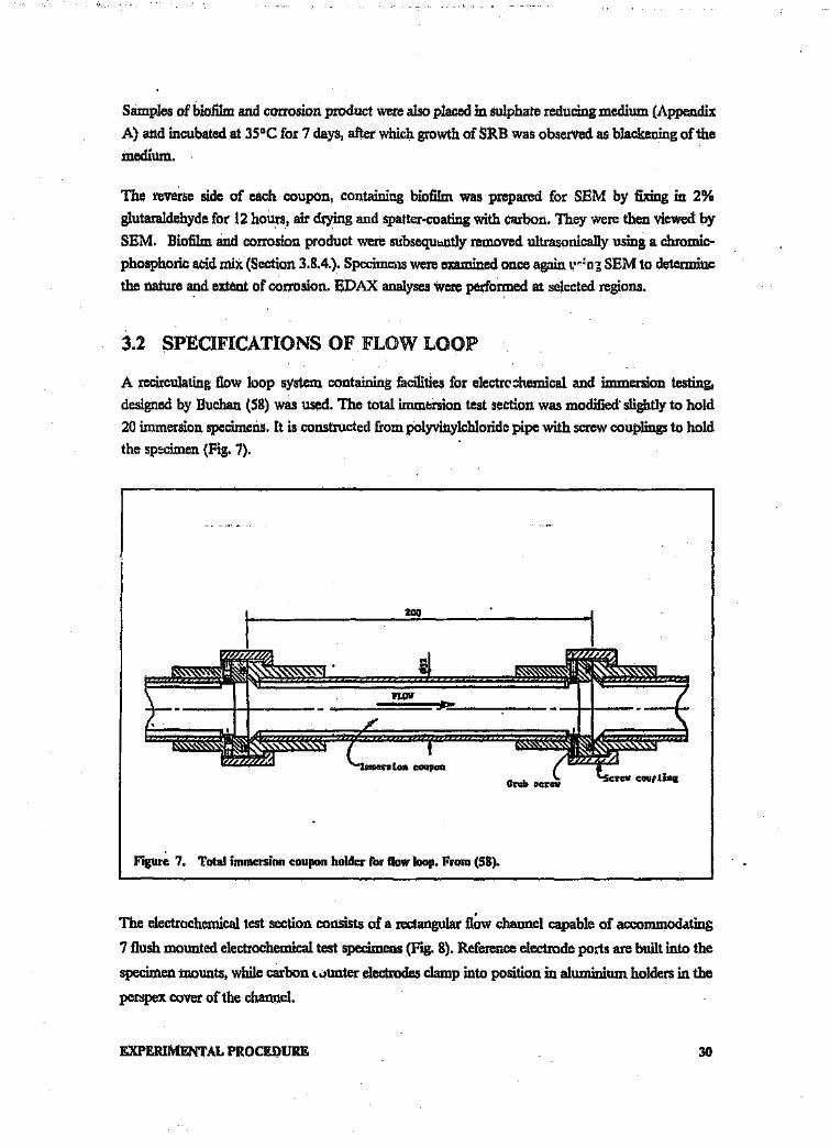
Samples of biofilm and corrosion product were also placed .in sulphate reducing medium (Appendix
A) and incubated at 35°C for 7 days, after which growth of SRB was observed as blackening of the
medium.
The reverse side of each coupon, containing biofilm was prepared for SEM by fixing in 2%
glutaraldehyde for 12 hours, air drying and spatter-coating with carbon. They Were then viewed by
SEM. Biofilm and corrosion product were subsequently removed ultrasonically using a chromic-
phosphoric acid mix (Section 3.8.4.). Specimens were examined once again 'L'~:'O5 SEM to determine
the nature and extent of corrosion. EDAX analyses were performed at selected regions.
3.2 SPECIFICATiONS OF FLOW LOOP
A recirculating flow loop system containing facilities for electrochemical and immersion testing,
designed by Buchan (58) was used. The total immersion test section was modified' slightly to hold
20 immersion specimens. It is constructed from polyvinylchloride pipe with screw couplings to hold
the specimen (Fig. 7).
Figure 7. Total immersion coupon holder for now loop. From (58).
The electrochemical test section consists of a rectangular fl~w channel capable of accommodating
7 flush mounted electrochemical test specimens (Fig. 8). Reference electrode ports are built into the
specimen mounts, while carbon counter electrodes clamp into position in aluminium holders in the
perspex cover of the channel.
EXPERIMENTAL PROCEDURE 30

The temperature of the water in the flow loop was maintained at 35 DC + 1o.
Perllpex top CO"ler Carbon counter electrode
1090Electrical connection1:0 I'Ipeeimen
Figure '8. Schematic of electrochemical corrosion test section. from (58).
Figures 9 and 10 illustrate the general layout of the flow loop. A O,55kW 220VAC pump draws
water from the tank, pumps it through the flowmeter and then through the Immersion Test Section
or bypasr ' The water then flows through the electrochemical test section or bypass no.2 before
returning to the tank.
EXPERIMENTAL PROCEJ)URE 31
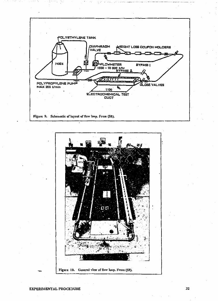
...POL YPROFlYLENE: PUMPMAX 200 Umin ,
ELECTROCHEMICAL TESTOUCT
Figure 9. Schcruatlc of layout of now loop, From (58).
Figure 10. (;c!lcrni view nf fluw loop. Frurn (58).
EXPEIUMENTAL PHOCEDURE 32

3.3 TEST lYIATERIALS
Four aluminium alloys (1070, 5182,6063 and 6261), a mild steel (MS) and a 3CR12 stainless steel
were used in the tests. All alloys were of commercial quality. The actual compositions of the sam-
ples used are listed below in Tables 1 and 2.
Table 1. Actual compositions of aluminium alloys used.
ALLOY %Cu %Mg %Si %Fe %Mn %Zn %Ti %Al
1070 0.000 0.003 0.075 0.13 0.000 0.007 0.005 99.93
5182 0.032 4.600 0.145 0.32 0.333 0.019. 0.017 94.65
6063 0.007 0.460 0.411 0.17 0.060 0.005 0.007 99.00
6261 0.016 0.737 1.080 0.17 0.560 0.006 0.006 97.53
Table 2. Actual composition of steels used.
ALLOY %C S P Mn Si Cu Zn Ti Mn ICr Ni
3CR12 ,020 ,003 ,019 1,19 ,51 ,05 ,04 ,25 ,02 11,2 ,60
MS ,03 ,014 ,016 ,20 ,01....__,
All alloys were tested in electrochemical scans and in the static immersion tests. The mild steel (MS)
and 3CR 12 alloys were not tested under flow conditions.
For the immersion tests under both static and flow conditions, all specimens were exposed in the
"mill-finish" state in order to approximate actual mining conditions. For tests vnder flow condi-
tions, anodized and conversion coated specimens were also tested.
EXPERlMENTAL PROCEDURE 33

3.4 BACTERIA USED IN TESTS
Both a pure and a mixed culture of SRB were utilized. The pure strain, purchased from the Na-
tional Collection of Marine and Industrial Bac-teria (Scotland), was Desulfovlbrio desulfuricansstrain Teddington R. The mixed strain was that isolated from the mine survey samples. A pure
strain of Pseudomonas aeruglnosa isolated from the mine samples was also used.
3.5 CULTIVATION OF BACTERIA
Bacteria Were cultured both in a nutritive medium and in mine water. The use of nutritive medium
ensures microbial growth under optimal conditions thus providing an aggressive, rapid test, repres-
enting the worst conditions. The mine water, however, simulates actual conditions.
3.5.1 Sulphate Reducing Medium
This medium used by Ringas (93), was utilized in these tests for both SRB and Pseudomonas cul-tures. The recipe for the base medium can be found inAppendix A. The base medium was prepared
in 1L Schott bottles, autoc1aved at 121cC for 20 mins and stored air-tight at 4°C until required.
Pseudornonads were cultured in aerated base medium. For SRB cultures, filter-sterilized redox
poising chemicals Were added to the base medium just before culturing. These consisted of a 2%
solution of sodium ascorbate and either a 7,8% solution of ferrous ammonium sulphate or a 2,6%
solution of ammonium sulphate, each added at a rate of 5 ml/litre of base medium.
3.5.2 Mine Water
WaM was collected from Durban Roodepoort Deep Mine Shaft 5 in a lOOOLgalvanized mild steel
tanker trailer. The water was left to stand for 3 days to allow any solids to settle, before being
t. msferred to the laboratory. The water had been treated with flocculants and lime. The composi-
t on of the water is listed in table 3.
EXPERiMENTAL PROCEDURE 34
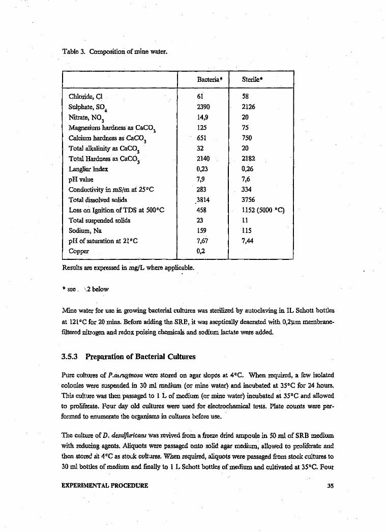
Table 3. Composition of mine water.
Bacteria+ Sterile?
Chloride, C1 61 58
Sulphate, so4 2390 2126
Nitrate, N03 14,9 20
Magnesium hardness as CaC03 125 75
Calcium hardness as CaCD 3 651 750
Total alkalinity as CaC03 32 20
Total Hardness as CaC03 2140 2182
Langlier Index 0,23 0,26
pH value 7,9 7,6
Conductivity in mS/m at 25°C 283 334
Total dissolved solids 3814 3756
Loss on Ignition ofTDS at 500°C 458 1152 (5000 0C)Total suspended solids 23 11
Sodium, Na 159 115
pH of saturation at 21°C 7,67 7,44
Copper 0,2
Results are expressed in mg/L where applicable.
'" see .2 below
Mine water for use in growing bacterial cultures was sterilized by autoclaving in IL Schott bottles
at 121°C for 20 mins. Before adding the SRE, it was aseptically deaerated with 0,21lm membrane-
filtered nitrogen and redox poising chemicals and sodium lactate were added.
3.5.3 Preparation of Bacterial Cultures
Pure cultures of Piaerugtnosa were stored on agar slopes at 4aC. When required, a few isolated
colonies were suspended in 30 ml medium (or mine water) and incubated at 35°C for 24 hours.
This culture was then passaged to 1 L of medium (or mine water) incubated at 35°C and allowed
to proliferate. Four day old cultures were used for electrochemical tests, Plate counts were per-
formed to enumerate the organisms in cultures before Use.
The culture of D. desulfuricans was revived from a freeze dried ampoule in 50 ml of SRB medium
with reducing agents. Aliquots were passaged onto solid agar medium, allowed to proliferate and
then stored at 4°C as stock cultures, When required, aliquots were passaged from stock cultures to
30 ml bottles of medium and finally to 1 L Schott bottles of medium and cultivated at 35°C. Four
EXPERIMENTAL PROCEDURE 3S

day old cultures were used in electrochemical tests and enumerated using the Most Probable
Number (MPN) test. Stock cultures of the mixed SRB were also stored on solid medium and
passaged and cultivated as for the SRB above.
3.6 ELECTROCHEMICAL TESTS
3.7 Specimen Preparation
Cylindrically shaped aluminium specimens (10 x 15 mm long) were prepared from extruded
aluminium rod. They were set in a polyester resin block with electrical connections made through
a self-tapping screw in the back onto which a wire was soldered. For specimens in the flow loop,
a 4mm diameter perspex tube was placed against and parallel to the specimen in the mould, so that
the reference electrode could be as close as possible to the corroding surface.
Mild steel specimens (15mm x lOmm diam.) were cut from rod and the electrical connection made
by soldering the wire onto the surface. 3CR12 specimens were machined from 3mm plate and used
in the form of discs of 15mm diameter, onto which a wire was soldered. As with the aluminium
samples, the steel samples were set in resin.
All specimens were wet ground to a [mal grit size of IOOOl1mon silicon carbide paper, rinsed in
water and finally degreased in acetone. The specimen/resin interface was masked with masking
lacquer (Mowat 45 Stop-off lacquer) t i prevent crevice formation.
3.7.1 Experimental Arrangement
For static electrochemical testing a one litre flask, with apertures for insertion of a Standard Calomel
reference electrode, carbon counter electrodes, gas inlet and outlet pipes and specimen holder, v-as
used.
Four day old bacterial cultures were used. These were poured into the corrosion flask which was
then sealed. Since direct deaeration of the .olution produced a pH change (93), the headspace only
was deaerated with Ultra-high pi ~ty nitrogen passed through a 0,2 11m membrane. The solution
itself was anaerobic due to the presence of the redox poising chemicals. The H2 S gas was bled into
a NaOII trap before being discharged to the atmosphere. In the case of Pseudomonas cultures,
aeration was achieved by bubbling compressed membrane-filtered air through the solution.
Both mine water and nutritive medium were used for electrochemical tests. Either ferrous
ammonium sulphate or ammonium sulphate ,1tse added with the sodium ascorbate to SRB me-
dium or mine water. Use of the former leads to the formation of iron SUlphide which was not de-
sirable in all cases.
EXPERIMENTAL PROCEDURE 36

The experimental set up for electrochemical tests itt the flow loop was described ill Section 3.2.
Electrochemical tests were conducted using a Princeton Applied Research Potentiostat/Galvanostat
Model 273 interfaced with an Apple II Computer and a Solartron Schlumberger 1286
Electrochemical Interface connected to a Cullinan Computer.
3.7.2 Potentiodynamlc Scans
A stabilization period of one hour was allowed before scanning commenced. This was fc=od to be
sufficient time for a stable Ecorr value to be reached Under flow conditions, scans were only
commenced once the free .corrosion potential had stabilized. Scans were run from 150mV below
Ecorr to a final potential of 1000 mY above Ecorr at a scan rate of I mY/so
Scans were conducted ill duplicate under the following conditions:
lit static tests in Pseudomonas cultures illmedium and in sterile medium as a control;
.,. static tests ill Ir.desutfuricans cultures illmedium containing ferrous ammonium sulphate and
ill sterile rr-edium containing the same j Jo'{ poising chemical as the control;
• static tests ill the mixed SRB culture under the same culture conditions as D. desulfuricans.
3.7.3 Cyclic Polarization Scans
Specimen preparation and stabilization times were the same as for the potentiostatic scans. Scans
were started at the free-corroding potential, Ecorr at a rate of 1 mY/s and then reversed at a current
density of lJO]lA/cm. Scans were performed in duplicate and sometimes ill triplicate.
Scans were carried out under the following conditions;
e Pseudomonas cultures in both medium and mine waters.
G Sterile, aerated mine water and nutritive medium.
.. D.desulfuricans cultures in both medium and mine water each containing either ferrous
ammonium sulphate or ammonium SUlphate.
Ii> Mixed SRB cultures in nutritive medium and mine water as above.
41 Sterile deaerated nutritive medium and mine water with the same redox poising chemicals as
above.
e A mixed culture of Pseudomonas and SRB inmine water under flow conditions.
• Sterile mine water under flow conditions.
EXPERIMENT AL PROCEDURE 37
Plots from the scans were examined to determine the effect of bacteria on:
.. the free corrosion potential Ecorr;
• the passivation range;
It the size of the hysteresis loop formed by the reverse scan.
3.7.4 Tafel Extrapolation
Specimen preparation and stabilization times were the same as for the potentiostatic scans. The
Tafel plots were obtained over a range of lOOmV at a sweep speed of lrnVjs starting from an initial
potential of -50m V from the rest potential. The cathodic and anodic slopes for tests in bacterial
cultures were compared with those in sterile medium in order to determine whether bacteria in fact
altered either the cathodic or anodic processes. Scans were conducted under the same conditions
as for cyclic polarization scans.
3.8 STATIC IMMERSION TESTS
3.8.1 Specimen Preparation
Coupons, 45 x 20 rom and ranging in thickness from 1,2 - 3,5 rom were machined from the six
different alloys. A 5 rom hole was drilled in the centre at one end. The edges of each specimen were
rounded and the holes chamfered to minimize edge corrosion effects. The dimensions of each cou-
pon were measured to an accuracy of 0,01 rom. They were then degreased ultrasonically in acetone
for 20 minutes and finally weighed to 0,1 mg. The edges and suspension holes were masked with
45 Stop-off Lecquer.
3.8.2 Experimental Arrangement
Triplicate specimens of each alloy were suspended on glass hangers in a random fashion in 2L
flasks. The lid and lip of each flask were greased and closed t, means of a clamp. The lid of the flask
contained ports for:
aeration/deaeration
fluid removal and addition
NaOH trap for H2 S bleed off.
Flasks with attached lengths of tubing and the specimens were autoclaved at 121°C for 20 minutes.
EXPERIMENTAL PROCEDURE 38

Four day old bacterial cultures in nutritive medium and in mine water and sterile controls were
aseptically added to each flask which was then incubated in a water bath at 35°C. SRB cultures and
corresponding controls were deaerated with ultra-high purity nitrogen gas which was passed
through a O,211IDmembrane filter, Pseudomonas cultures and controls were aerated with com-
pressed air passed through a similar filter,
A semi-continuous culture technique was used ie periodic removal of exhausted medium and cells
followed by addition of fresh medium. This involved removal of 100-200 m1 fluid twice a week
with replacement of the same amount of fresh medium. This technique maintains the cells in a state
of active growth. Strict aseptic conditions Were maintained throughout the duration of the tests.
Figures 11 and 12 show the specimen jar and the lid with various attachments.
Figure 11. Corrosion flask with immersion specimens.
EXPERIMENTAL PROCEDURE 39

Figure 12. L.id of' corrosion flask used in immersion tests showing ports: A - Inlet for fresh medium Ijoined to a reservoir; B - Nitrogen gas bubbler and outlet port for H2 S
C - Outlet for exhausted medium
Medium was extracted by clamping off port A and the H2 S outlet port, and bubbling gas through
the medium. The pressure build up forced the fluid through port C. The gas was then turned off
and fresh medium allowed to flow through A. Tygon tubing was used throughout; The tubing can
be autoclaved for sterility and is impervious to oxygen.
The water bath was housed in a wooden cabinet illuminated by a germicidal UV lamp in order to
decrease chances of contamination from the atmosphere.
3.8.3 Specimen Examination
After an exposure period of 7 weeks, the samples Were removed from the flasks and photographed
immediately. One sample from each set was prepared for SEM by fixing in 2% glutaraldehyde for
12 hours and then drying in a desiccator. These samples were then coated with carbon and the at-
tached biofilm and corrosion product viewed. Qualitative EDAX was used to analyse corrosion
products. Some samples were then gold coated for improved visualization of the biofilm.
The surfaces of the coupons were then cleaned (see below) and re-examined by SEM for corrosive
attack.
EXPERIMENTAL PROCEDURE 40

1/
Optical microscopy was also used to examine cleaned specimens. The cleaned specimens were re-
weighed and weight losses calculated.
3.8.4 Specimen Cleaning
The cleaning procedure involved scrubbing of the specimens with a nylon brush under running tap
water and then immersion for half an hour .in a chromic acid/phosphoric acid mixture (Appendix
B) at 25 "C. During immersion in the acid, the specimens were scrubbed twice with a nylon brush.
They were then rinsed 1..1 tap water anu finally in acetone. The ..)! were tnen dried on paper towels
-md stored if' ...desiccator.
3.9 FLOW LOOP IlVlil\tlERSIONTESTS
3.9.1 Specimen Preparation
Test specimens cut to size were prepared in the same way as for static immersion tests.
3.9.2 Experimental Arrangement
Specimens were inserted into the immersion section of the flow loop. Tests were. run in sterile mine
water which was treated with biocide (Chemserve Bioshock) at a dosage of 50 mg/l/week. Weekly
bacteriological plate counts were carried out to ensure sterility of the water. The flow rate was set
at 1,5 m/s. The temperature reached a maximum of 35°C without cooling. Samples were exposed
for 7 weeks.
Due to breakdown of the pump seal after the sterile immersion tests, this water was lost. Additional
mine water was collected from the same spot as before and analysis showed it to be of very similar
composition to the first water (Table 3).
This water was left unsterilized, Five litres of 4 day old cultures of Piaeruginosa were- add id to the
water and allowed to proliferate for 1 week before insertion of new specimens. After 1 "Neck's ex-
posure to the Pseudomonads, during which time it was hoped that a slime layer had formed on the
specimens, 5 lines of 4 day old D. desulfuricans culture were added to the tank. The total exposure
time of the specimens was I WCI.>''-:-:'
3.9.3 Specimen Evaluation
This was carried out as for the static immersion tests.
EXPERIMENTAL PROCEDURE 41

3.9.4 Specimen Cleaning
As for static immersion tests.
EXPERIMENTAL PROCEDUHE 42

4.0 RESULTS
4.1 MINE SURVEY RESULTS
4.1.1 Microbial isolation and identification
FSG samples
All FSG tes; specimens were covered with thick slimy growths together with fungal and mould
species. The condition of some of the coupons on removal from the test rig can be Seen in Figs.
13 - 16.
Figure 13. Alloy 1200 in the condition as removed from the system.
RESULTS 43

Figure 14. Alclad coupons in the condition as removed from the system.
Figure lS. Alloy 52:;1 in the condition as removed from the system.
RESULTS 44

Figure 16. Alloy 6261 in the condition as Itcmoved from the system.
Some fungi were identified as belonging to the following genera:
(I Altenaria
o Curvularia
e Rhizopus
G Cladosporium (possibly)
Colony and spore morphologies are illustrated in Figs. 17 • 21.
RESULTS 45

----~----- ----------------------------------------------------------,
Figure 17. Possible Cladosporium colonies..
Figure 18. Fungal, mould and yeast colonieson Sabouraud Dextrose agar.
RESULTS 46

---------------------,
Figure 19. Spores of the fungus Altenaria (Mag. iOOx),
,--------------------------------------------" ----.-----------,
I~
Figure 20. Spores of the fungus Curvularia (Mag. I.000 x),
RESULTS 47
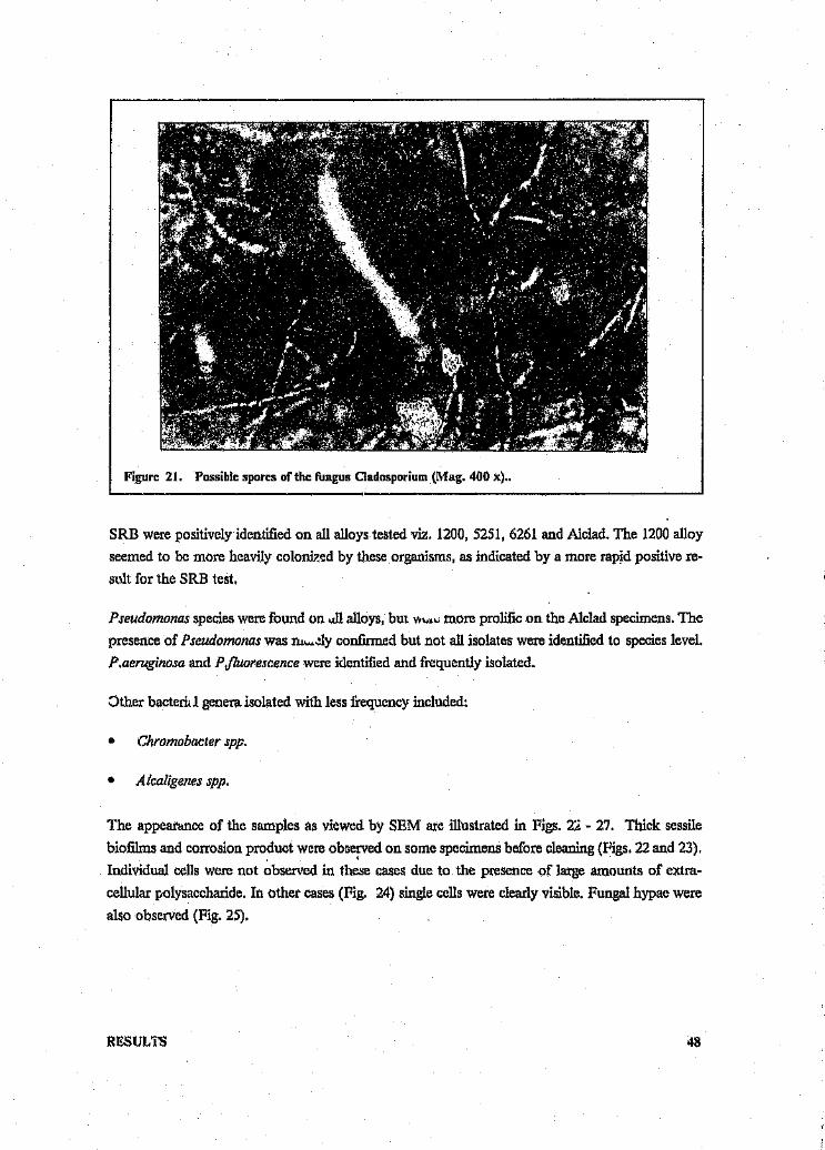
Figure 21. Possible spores of the fungus Cladosporium (Mag. 400 x) ..
SRB were positively identified on all alloys tested viz. 1200, 5251, 6261 and Alc1ad. The 1200 alloyseemed to be more heavily colonized by these organisms, as indicated by a more rapid positive re-stilt for the SRB test.
Pseudomonas species were found on <.(11alloys, but v." • ..;more prolific on the Alclad specimens. Thepresence of Pseudomonas was nl"•ely confirmed but not all isolates were identified to species level.Ptaeruginosa and P fluorescence were identified and frequently isolated.
Other bacteri. 1 genera isolated with less frequency included:
e Chromobacter spp.
.. Alcaligenes spp.
The appearance of the samples as viewed by SEM are illustrated in Figs. 2Z - 27. Thick sessilebiofilms and corrosion product were ob3cfVed on some specimens before cleaning (Figs. 22 and 23).Individual cells were not observed in these cases due to the presence of large amounts of extra-cellular polysaccharide. In other cases (Fig. 24) single cells were clearly visible. Fungal hypae werealso observed (Fig. 25).
RESULTS 48

Figure 22. Biofilm on Alclad specimen before cleaning.
I Figure 23. Biofilm on alloy 6261 before cleaning.
RESULTS 49
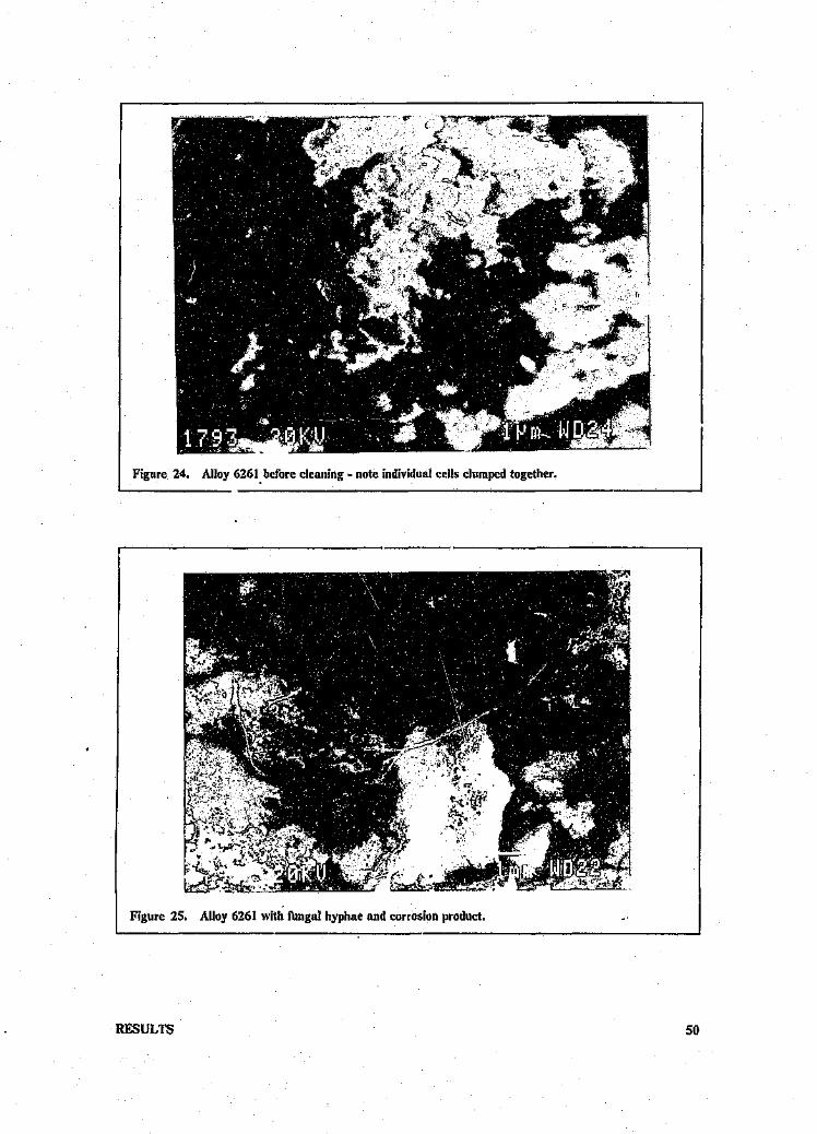
Figure 24. Alloy 6261. before cleaning ~ note individual cells clumped together.
r-~~~------------------------------------.
Figure 25. Alloy 6261 with fungal hyphae and corrosion product.
RESULTS 50

WDLsamples
In contrast to FSG samples, WDL samples (viz. 1200, 5251, 6261, Alclad, painted, conversion
coated, anodized) were not as heavily colonized by microorganisms.
The 1200 and A1clad alloys exhibited the most biological growth, whilst the 6261 alloys were
heavily encrusted with scale. The conversion coated and painted coupons were covered b}' a thin,
easily removable brown film, The 5251 and anodized alloys appeared to have remained
uncolonized.
Fungal and mould species were isolated from all coupons, but these were not identified to species
level.
Pseudomonas spp, were isolated from 1200, 6261 and the conversion coated alloys.
SRB were positively identified on 1200, 6261 and Alclad specimens.
SEM revealed that all specimens were covered with biofilm (Fig. 26). Tubercles covered with
bacteria were also observed (Fig. 27).
Figure 26. Biofllm on conversion coated specimen.
RESULTS 51

Figure 27. Tubercle on specimen 6261.
4.1.2 Examination of corroded surfaces,
Samples exposed to FSG waters
On removal of the biofilm, the surfaces were found to have undergone noticeable corrosion and
showed evidence of exfoliation and pitting. Figs. 28 - 31 show the condition of some alloys in the
acid cleaned condition.
RESULTS 52

Figure 28. Alloy 1200 in the acid cleaned condition.
Figure 29. Alloy 5251 in the acid cleaned conditiorr,
RESULTS 53

Figure 30. Alclad in the acid cleaned condition,
('
Figure 31. View of alloy 6261 after cleaning.
The acid cleaned specimens examined by SEM revealed pitting attack of all alloys (Figs. 32 - 34).
Intergranular attack was present in alloy 121)0(Fig. 35). inwhich the triple points (If corrosion ini-tiation are clearly visible.
RESULTS 54

EDAX analysis showed that sulphide precipitates were present in abundance, often at the bottomof pits (Fig. 36).. \n EDAX trace is shown in Fig. 37. Newman et at (94) in a study of the effectsof sulphur compounds on the pitting behaviour of 304L stainless steel innear neutral chloride sol-utions, found metal sulphides at the bottom of pits formed in the presence of sulphide, thiosulphatecr tetrathionate, They suggested that the active sulphur species enhance corrosion by impeding therepassivation of the bare metal surface following chloride induced film breakdown. This mode ofSUlphidepitting could well apply to the aluminium alloy samples.
Figure 32. Pitting attuck on Alclad.
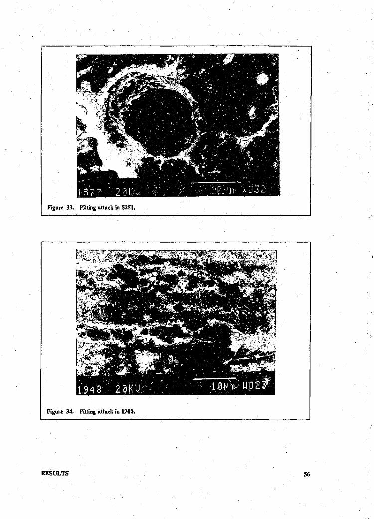
Figure 33. Pitting attack in 5251.
RESULTS
Figure 34. Pitting attack in 1200.
56

Figure 35. Intergranular attack in 1200.~-------------------------- ---_.--------------,--------
r---------~------------.----------------------~-~~.--------------------,
Figure 36. Sulphide precipitates in pits.
RESULTS 57

A1
Figure 37. EDAX trace or precipitates in Fig. 36.
Samples exposed to WDL water
The condition of the surfaces On removal of the biofilm can be seen in Figs. 38 - 40. Pitting attackwas present in 1200, 5251, 6261, Alclad and conversion coated specimens (Figs. 41 and 42). Al-though the C(Y .ersion coated specimen seemed undamaged macroscopically, at the SEM level ofexamination, it showed damage in the form of intergranular attack and pitting (Fig. 43). The 1200coupon also showed signs of intergranular attack (Fig. 44). The 5251 specimen showed microscopicdamage in the form of interlinkin.; pits in the duection of the extrusion lines (Figs. 45 and 46).
RESULTS 58

5251
Figure 38. Condition of coupons after biofilm removal.
Figure 39. Condition of coupons after biofilm removal.
RESULTS 59

Figure 40. Condition of coupons after biofilrnremoval.
Figure 41. Pitting on the surface of a 6261 specimen,
RESULTS 60
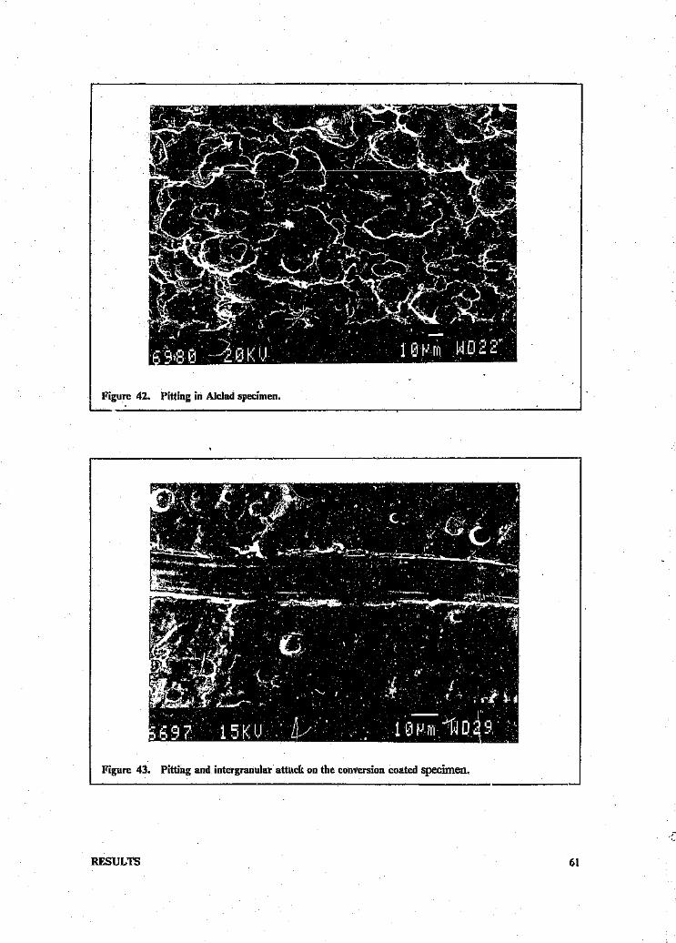
, Figure 42. Pitting in Alclad specimen.~--'~--------~------------------------~----------------------~
Figure 43. Pitting and intergranular attack on the conversion coated specimen.
RESULTS 61

Figure 44. Intcrgranular attack on alloy 1200.
Figure 45. Pits in the di.l'ection of extrusion lines in alloy 5251.
RESULTS 62

Figure 46. Close up Jf Fig. 45 showing pits.
4.2 IlVIMERSIONTESTS - STATIC
The condition of the alloys on removal from the flasks can be seen in Figs. 47 - 56.
The.alaminium alloys immersed for seven weeks in the SRB cultures in medium were covered by
a thin greyish film and discrete black patches, all of which were easily scraped away. The mild steel
coupons were covered by a thick black adherent layer which could not be scraped away. Tubercles
were visible over the entire surface. The 3CR12 coupons revealed a few black tubercles, but ether-
wise were covered by a thin grey film.
,In. mine water tests, the aluminium alloys were covered by a thin easily removable brown corrosion
product layer. Discrete black patches were found on the 6-series alloy specimens. The correspond-
ing mild steel coupons were covered by a thick black corrosion product and tubercles. Discrete
black patches covered the 3CR12 coupons.
Coupons immersed in sterile deaerated medium were covered by a thin off-white film which was
easily removed. The mild steel coupons exhibited a typical reddish-brown corrosion product.
All coupons in the deaerated mine water were covered by a thick film of aluminium hydroxide.
Coupons in the Pseudomonas cultures, both in medium and in mine water, were covered by a
bulky, brown coloured corrosion product which was easily removed. Control coupons in sterile
RESULTS 63

mine water and medium were covered by a thin white film and a yellow-brown film respectively.
The films adhered loosely.
Figure 47. Condition of' coupons on removal from the static immersion tests: in a mixed SRB culture
in mediumL ~~ ~
The samples shall be referred to as follows.-
1 - 1070
2 - 510':
3 - 6063
4 - 6261
5 - 3CR12
6 - mild steel
RESULTS 64

Figure 48. Condition of coupons on removal from the static immersion tests: in D.desulfuricans culture
in medium.
25 6
Figure 49. Condition of coupons on removal from Pseudomonas culture inmedium.
RESULTS 6S

42 6
,.
"'1I1innJ.lfmn _. I1Impmrrrnrrmll"~mllYllT!llnlllllllllillnm.mlPlIifmlI!It~nllflUlllmIUIlI!lIllmqmIllftiltlTIiiilo L 2 3 1 & 6 7 8. 9' 10 11 Ii t3 l~
m(~t.n.~ ?£.',y ).,11 ~:::::...
Figure 50. Condition of coupons on removal from aerated Pseudomonas medium (control).
Figure 51. Condition of coupons on remuvnl from dcaerated SRB medium (control)
RESULTS 66

Figure S:Z. Condition of COUpOI.:; on removal from D.desulfuricans culture inmine water.,----_..._----,--------------'
Figure 53. Condition of cnupons on removal from the mixed SRB culture inmine water.
RESULTS 67

Figure 54. Condition of coupons on removal from the Pseudomonas culture in mine water.
Figure 55. Condition of coupons on removal from sterile deaerated mine water
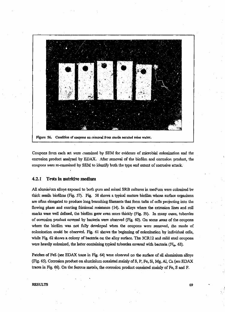
Figure 56. Condition of coupons 011 removal from sterile aerated mine water.
Coupons from each set were examined by SEM for evidence of microbial colonization and the
corrosion product analysed by EDAX. After removal of the biofilm and corrosion product, the
coupons were re-examined by SEM to identify both the type and extent of corrosive attack.
4.2.1 Tests in nutritive medium
All aluminium alloys exposed to both pure and mixed SRB cultures in medium were colonized bv
thick sessile biofilms (Fig. 57). Fig. 58 shows a typical mature biofilm whose surface organisms
are often elongated to produce long branching filaments that form tufts of cells projecting into the
flowing phase and exerting frictional resistance (14). In alloys where the extrusion lines and roll
marks were well defined, the biofilm grew even more thickly (Fig. 59). In many cases, tubercles
of corrosion product covered by bacteria were observed (Fig. 60). On some areas of the coupons
where the biofilm was not fully developed when the coupons were removed, the mode of
colonization could be observed. Fig. 61 shows the beginning of colonization by individual cells,
while Fig. 62.shows a colony of bacteria on the alloy surface. The 3CR12 and mild steel coupons
were heavily colonized, the latter containing typical tubercles covered with bacteria (Fi",. 63).
Patches of FeS (see EDAX trace in Fig. 64) were observed on the surface of all aluminium alloys
(Fig. 65). Corrosion product on aluminium consisted mainly of S, P, Fe, S1, Mg, Al, Ca (see EDAX
traces in Fig. 66). On the ferrous metals, the corrosion product consisted mainly of Fe, S and P.
RESULTS 69

Figure 57. Biofilm on alloy 6261 in mixed SRB culture in medium: Note remnants of glycocalyx.
RESULTS
Figure 58. Alloy 1070 in D.desulfurieans culture in medium: Note branching of cells.
70

Figure 59. Thick biofilm between extrusion lines of alloy 6261: in Ii.desulfuricans culture,
Figure 60. Tubercle coveredwith bacteria: Alloy 6261 In Il.desulfuricans culture.
RESULTS 71

Figure 61. Initial colonization by Desulfovibrio on alloy 5182.
Figure 62. Later development of a colony of Desuli'ovibrio cells.
RESULTS 72

Figure 63. Tubercles covered with bacteria on mild steels in Ir.desutfurioans culture in medium.
F,
:1/;l! F~
_'" J'I /;', ,1\F
Figure 64. EDAX trace of FeS patches on alloys.
RESULTS 73
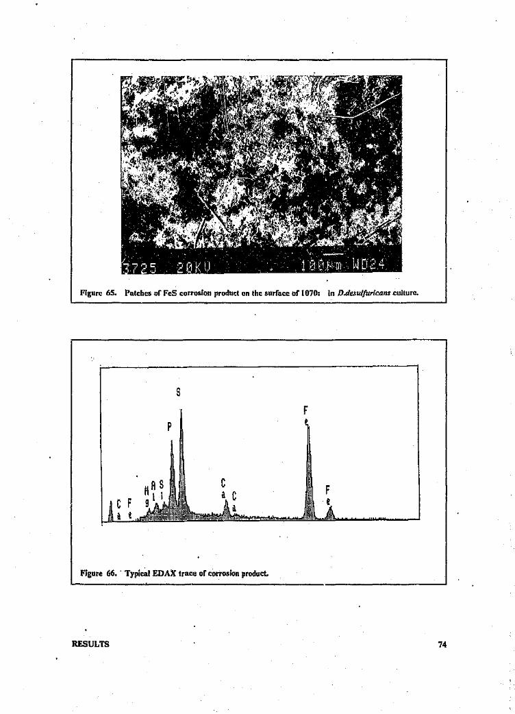
Figure 65. Patches Dr feS corrosion product on the surface of 1070: in D.desulfuricans culture.
sF
F~
p
Crl
Figure 66 .. Typical EDAX trace of corrosion product.
RESULTS 74
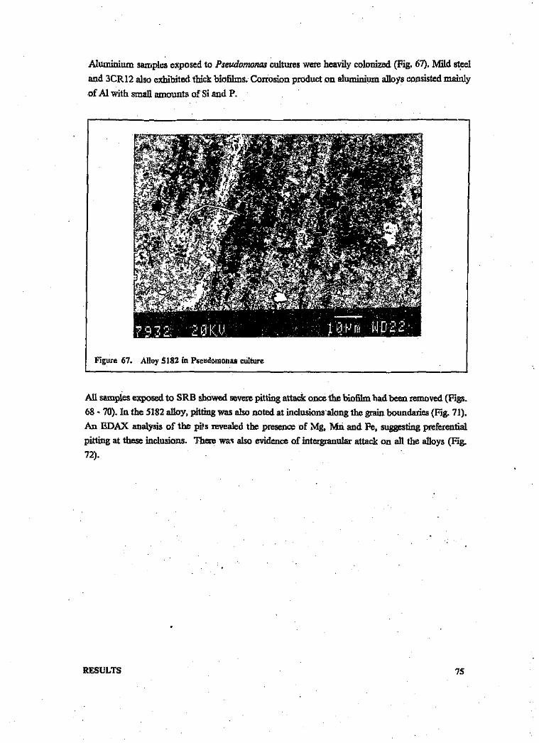
Aluminium samples exposed to Pseudomonas cultures were heavily colonized (Fig. 67). Mild steel
and 3CR12 also exhibited thick biofilms. Corrosion product on aluminium alloys consisted mainly
of AI with small amounts of Si and P.
Figure 67. Alloy 5182 in Pseudomonas culture~------------------------------------,------------------------------All samples exposed to SRB showed severe pitting attack once the biofilm had been removed (Figs.
68 - 70). In the 5182 alloy, pitting was also noted at inclusions along the grain boundaries (Fig. 71).
An EDAX analysis of the pits revealed the presence of Mg, Mn and Fe, suggesting preferential
pitting at these inclusions. There was also evidence of intergranular attack on all the alloys (Fig.
72).
RESULTS 75

Figure 68. Start of a pit under a tubercle: Alloy 1070 in mixed SRB culture.
Figure 69. Alloy 6063 after immersion in a mixedSRB culture.
RESULTS 76

Figure 70. Pitting in mild steel.
Figure 71. Pitting in alloy 5182: after immersion in D.desulfuricans culture.
RESULTS 77
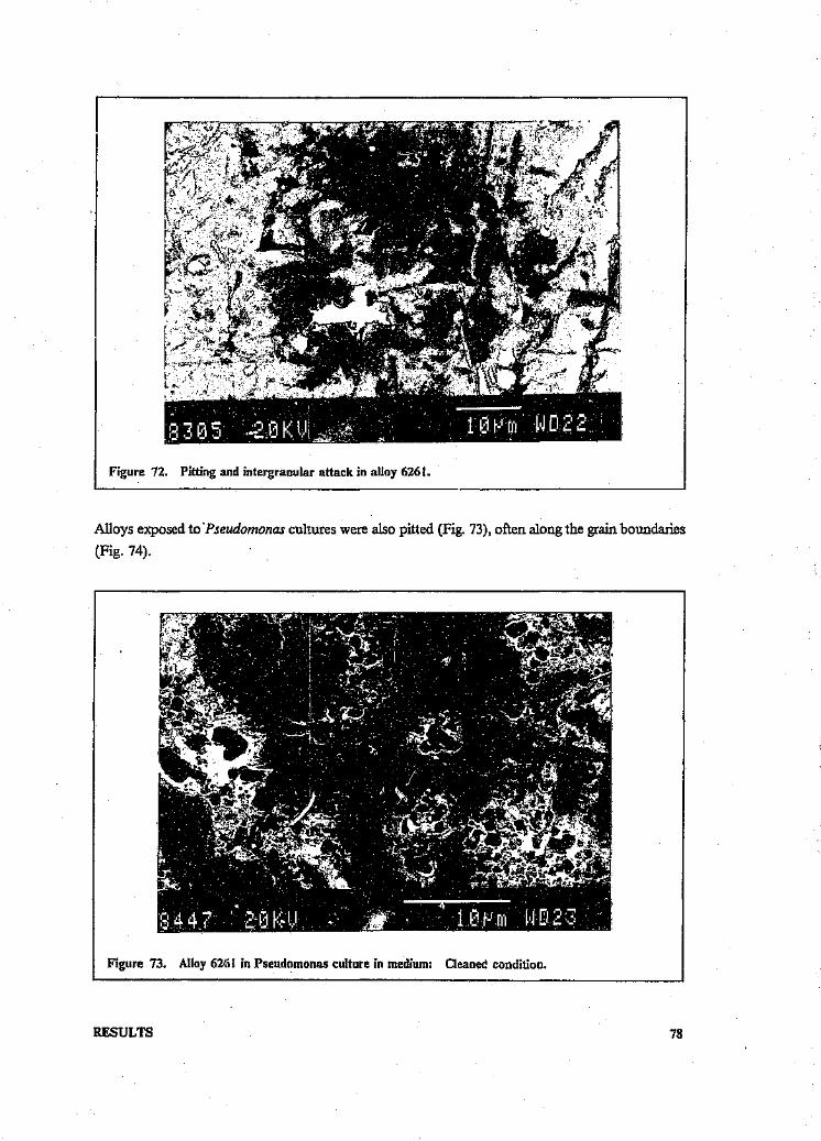
Figure 72. Pitting and intergranular attack in alloy 6261.
II
Alloys exposed to .Pseudomonas cultures were also pitted (Fig. 73), often along the grain boundaries
(Fig. 74).
Figure 73. Alloy 62/.i1 in Pseudomonas culture in medium: Cleaned condition.
RESULTS 78
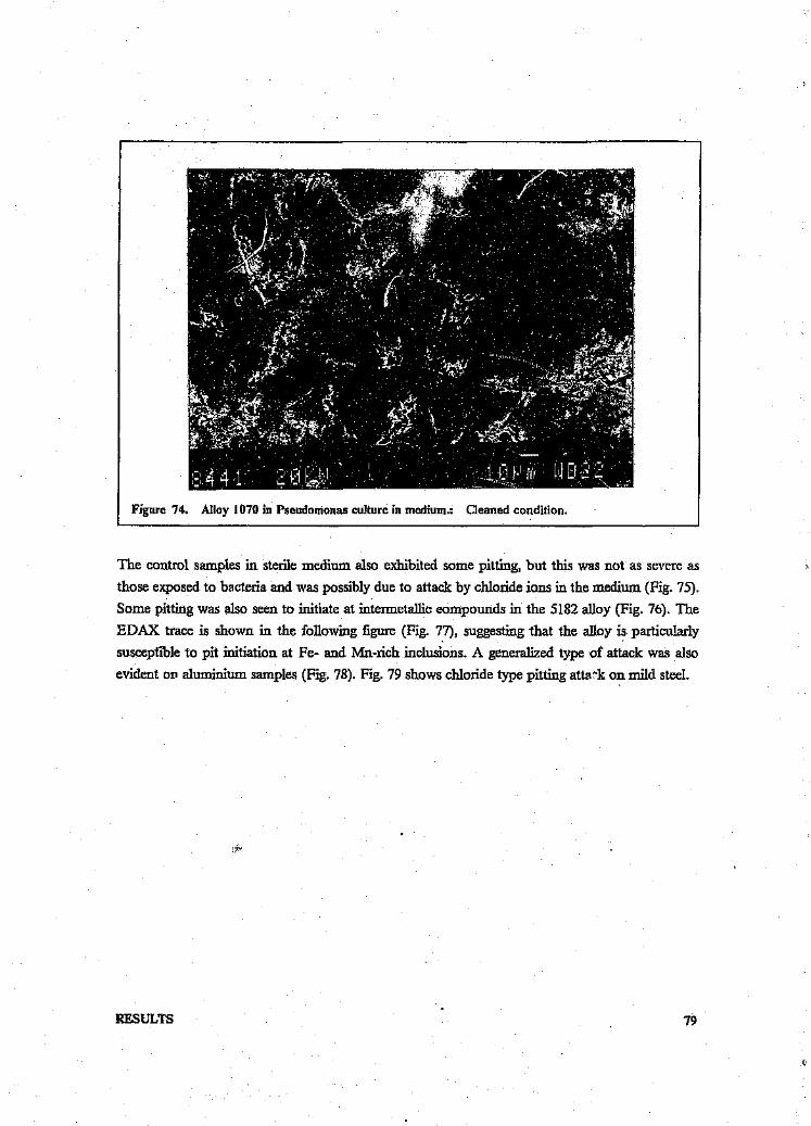
Figure 74. Alloy 1070 in Pseudomonas culture in medium.: Cleaned condition.
The control samples in sterile medium also exhibited some pitting, but this was not as severe asthose exposed to bacteria and was possibly due to attack by chloride ions in the medium (Fig. 75).Some pitting was also seen to initiate at intermetallic eompounds in the 5182 alloy (Fig. 76). TheEDAX trace is shown in the following figure (Fig. 77), suggesting that the alloy is particularlysusceptible to pit initiation at Fe- and Mn-rich inclusions. A generalized type of attack Was alsoevident 011 aluminium samples (Fig. 78). Fig. 79 shows chloride type pitting attack on mild steel.
RESULTS 79

Figure 75. Pitting ill alloy 1070 in sterile SRB medium.
Figure 76. Pit at inclusion in 5182 in sterile SRB medium.
RESULTS 80

11 Fe
H Fe
Figure 77. EDAX (If intermetallic compounds in 5182 alloy.
Figure 78. Alloy 6;26l in sterile SRB medium.
RESULTS 81

Figure 79. Chloride pitting in mild steel in sterile SRO medium.
4.2.2 Tests in mine water.
The mixed SRB culture in mine water colonized the aluminium alloys showing the typicalelongated filaments with tufts of cells (Fig. 80). Individual colonies in the process of dividing toform coherent biofilm were observed (Fig. 81). Masses of bacteria and corrosion product werecommon on the surface (Fig. 82).
3CRl2 and mild steel specimens were more heavily colonized (Fig. 83). Tubercles covered wi,»bacteria were common (Fig. 84).
RESULTS 82

Figure 80. Alloy 6261 in a culture of mixed SRB in mine water.
Figure 81. Individual bacterial colonies on 6063 in mixed SRB' culture in mine water: Not.e inter-
linking by glycocalyx strands.
RESULTS 83

Figure 82. Tuberc'e and bacteria on alloy 5182: in mixed SRG cultu J(te water,,__--~------------------."-,--
Figure 83. Biofilm on 3CR12 in mixed SRB ,culture in mine water.~~-----------------------------------------------------------~
RESULTS 84

Figure 84. Hollow tubercle on mild steel: in mixed SRB culture in mine water.
In the Didesulfuricans culture, colonization of the aluminium alloy surfaces was sparser than in the
mixed SRB culture. nus was especially so on the 1070 an~ 5182 alloy surfaces where few to no cells
were observed. Biofilm did, however, develop on the 6-series alloys (Fig. 85).
Colonization of 3CR12 and mild steel was well developed as shown by the thick biofilm develop-
ment (Fig. 86). Tubercles on the mild steel surface are depicted in Fig. 87.
RESULTS 85

Figure 84. Hollow tubercle 011 mild steel; in mixed SRB culture in mine water,
In the D .desulfuricans culture, colonization of the aluminium alloy surfaces was sparser than in the
mixed SRB culture. This was especially so on the 1070 an15182 alloy surfaces where few to no cells
were observed. Biofilm did, however, develop on the 6-series alloys (Fig. 85).
Colonization of 3CR12 and mild steel was well developed as shown by the thick biofilm develop-
ment (Pig. 86). Tubercles on the mild steel surface are depicted in Fig. 8"/.
RESULTS 85

Figure 85. Biofilm on 6063 in Didesulfuricans culture in mine water.
Figure 86. Surface of 3CR12 after immersion in D.desulfuricans culture in mine water.
RESULTS 86

Figure 87. Tubercles on mild steel in D'.desulfuricans culture inmine water.
Corrosion product on' aluminium alloys contained mainly Al, P, S, Ca, Fe (EDAX traces in Fig.88). FeS was the main corrosion product on the ferrous metals.
Both aluminium and ferrous coupons were well colonized by Pseudomonads. The surfaces weretypically covered by mounds of bacteria. and large amounts of corrosion product (Fig. 89), TheEDAX trace of corrosion product from Fig. 89 appears in Fig. 90.
RESULTS 87

s
Figure 8M. EDAX of corrosion product 011 aluminium alloys.
Figure 89. Mounds of bacterial growth and corrosion product on 5182: in Pseudomonas culture illmine water.
RESULTS 88

G Fe
Figure 90. I!.DAX of corrosion product.
It Was difficult to compare the type of corrosion damage on aluminium coupons in the deaeratedmine water. This was due to the fact that the control coupons also underwent severe corrosion.This seemed to be mainly in the form of selective dissolution of a certain phase and severe pittingof the remaining phase (Figs. 91 and 92). Minimal damage was observed on the ferrous samples.
RESULTS 89
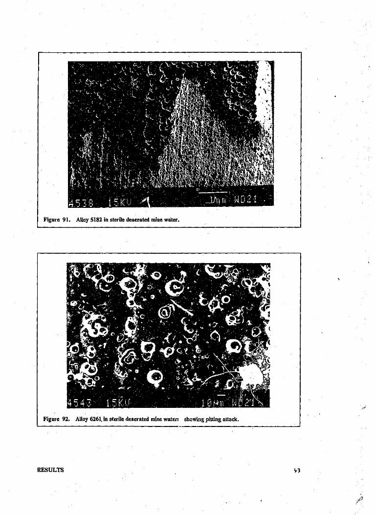
Figure 91. Alloy 5182 in sterile deaerated mine water.
I Figure 92. Alloy 6261, in sterile deaerated mine water: _s_h_o_w_i_n_g_p_it_ti_n_g_a_tta__c_k_, ~__ __,
RESULTS

Coupons exposed to D,d;:suifuricans cultures were damaged by pitting attack especiallyin the caseof the 6-series alloys (Fig. 93). In some cases, this was seen to follow the grain boundaries (Fig.94). The 1070and 5182 alloys tended to show selectivephase attack as in the controls (Fig. 95).
RESULTS
Figure 93. Pitting in alloy 6261: after immersion in Is.desulfuricans culture in mine water,
\
91

c
Figure 94. Pitting along grain boundaries: AHoy 6063 in Ii.desulfuricans culture in mine water.
Figure 95. Alloy 6063 in D.desulfuricans culture in mine water.
RESULTS 92
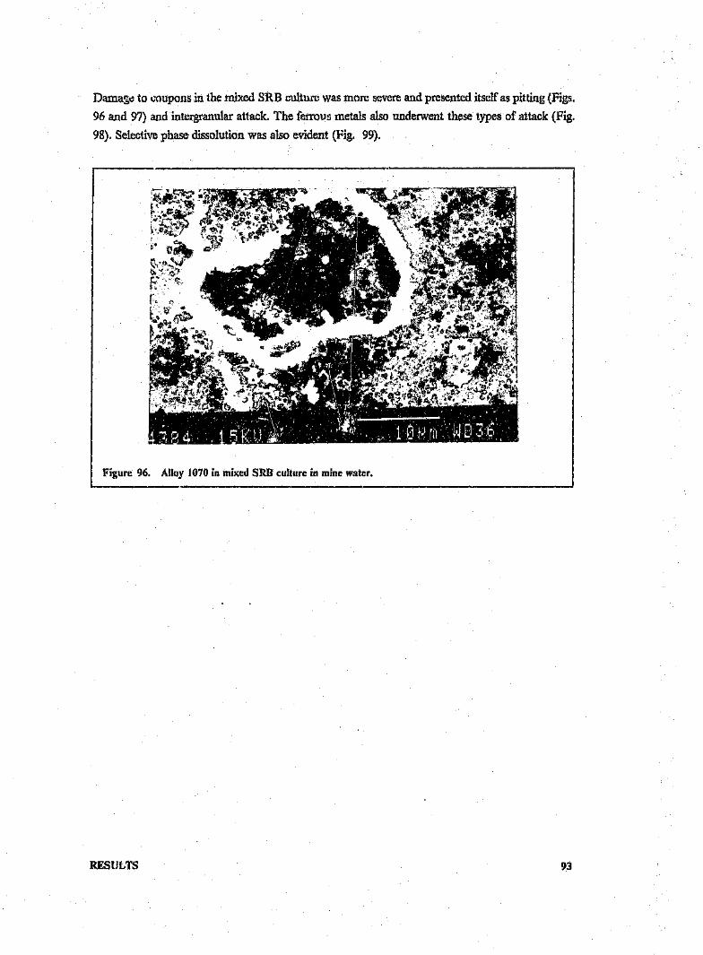
Damage to coupons in the mixed SRB culture was more severe and presented itself as pitting (Figs.96 and 97) and intergranular attack. The ferrous metals also underwent these types of attack (Fig.98). Selective phase dissolution was also evident (Fig. 99).
---------------------------------.~------------------------,
Figure 96. Alloy 1070 in mixed SRn culture in mine water.
RESULTS 93

Figure 97. Pitting in alloy 6063 ill mixed SRB culture in mine water.
Figure ;)8. Intergranular corrosion of mild steel: in mixed SRB culture in mine water,
RESULTS 94

Fignee 99. Selective corrosion of phases and pitting in 5182: in mixed SRB culture in mine water.
Pitting was found on samples exposed to Pseudomonas cultures in mine water. This seemed to in-itiate at inclusions especially, in the 5182 alloy (Figs. 100 and 101). Fig. 102 is the EDAX trace of
the inclus.; ••.. *'1 this alloy and shows a small amount of Mg and preferential pit initiation at Fe-
and Mn-rich intermetallic compounds. Intergranular attack (Fig. 1(3) and selective phase attack
(Fig. 104) were also observed.
RESULTS 95
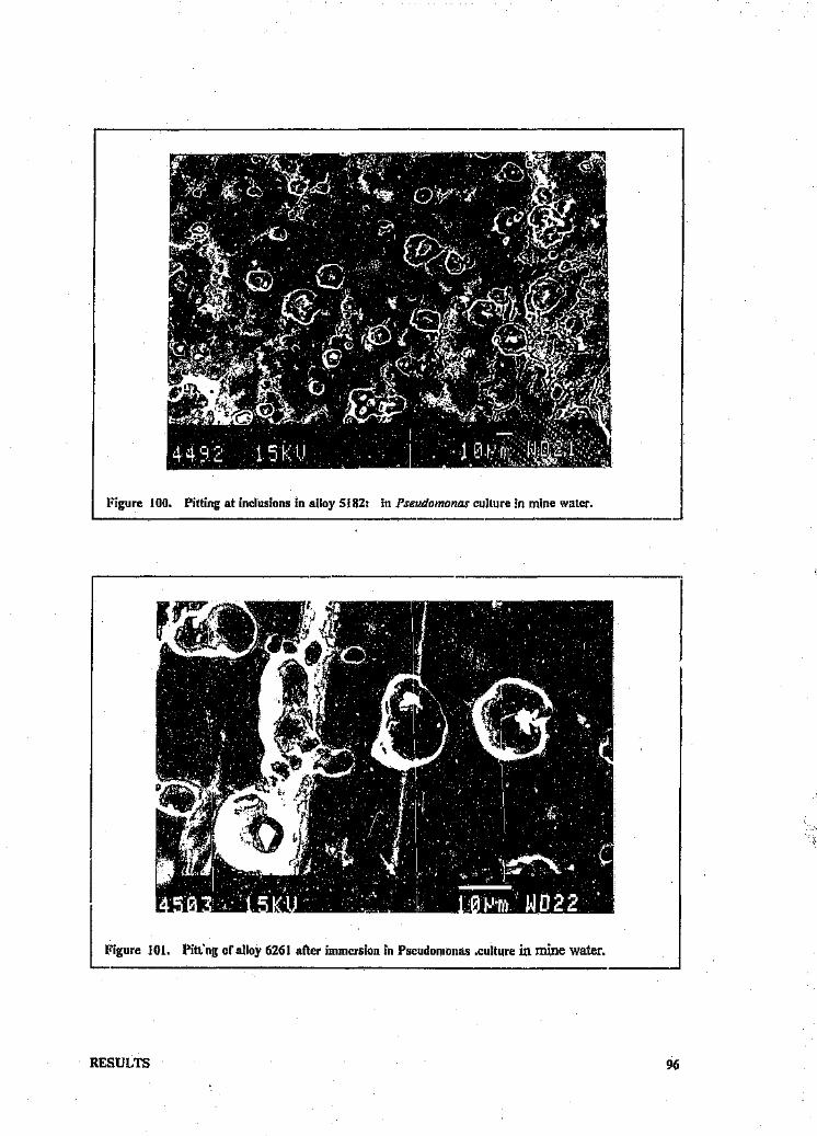
JFigure 100. Pitting at inclusions in alloy 5182; in Pseudomonas culture in mine water.
RESULTS
101. Pitt'ng of alloy 6261 after immersion in Pseudomonas .culture in mine water.
96

F~
1'1
;,,~t",i~~i~~!,lIk""""'JM1.i. Ft,
il;1:
I Figure 102. EDAX trAce of incIUs_i_on_ln_S_I_8_2_R_"_OY_" _
I Fig." '.3, AlI.y6063 i•• "'.d ....... ,"".,e i... ;•• ""tot,
RESULTS 97

Figure 104. Selective attack of phases in 1070: in Pseudomonas culture in mine water.
Pitting attack was observed in the control samples, though not as severe as in the bacterial cultures
(Fig, 105). This also seemed to nucleate at inclusions.
rI
RESULTS
Figure 105. Alloy 1070 ill sterile aerated mine water.
98

4.2.3 Weight Loss test results.
Weight loss test results for the alloys exposed under different conditions are depicted in the diagramsbelow (Fi),;s. 106 and 107). Actual values may be found in the table in Appendix. C.
WEIGHT LOSS RESULTSMedium
WEIGHT LOSS Cmg/cm2)6r---------------~----~~--~------------~----__,5~---·-"·-,-·--------·--------------------·--------·----4r··---------·-------·--··-----·------,-------------------
5182 6063 6261ALLOYS
3CR12 Mild steel1070
_ D.aesulfurloans
_ Pseudomonas
_ Mixed SRB
IiiliiliI Control (Ps)
EIJ Control (SRB)
Figure 10/
RESULTS 99

4.2.3 Weight Loss test results.
Weight loss test results for the alloys exposed under different conditions are depicted in the diagrams
below (Figs. 106 and 107). Actual values may be found in the table inAppendix C.
WEIGHT lOSS RESULTSMedium
WEIGHT LOSS (mg/om2)6r-----------~~----~--------------------------~
4r----··-----------·--------------------------------
2
6063 6261ALLOYS
3CR12 Mild steel1070 5182
II! o.aesutturtoene_ Pseuaomonee
_ Mixed SRB
Iilliilil Oontrol (Psl
[2] Oontrol (SRB)
Figure 107
RESULTS 99

WEIGHT LOSS RESULTSMine water
WEIGHT LOSS (mg/cm2)'::==:=====::======.-~~~~~~~~~~-----_-_-_-·-=1
40
60~----------+n---------·------
1070 5182 6063 6261ALLOYS
_ MIxed SRB
lliiiill Oontrol (Ps)
[£JJ Oontrol (SRB)r,. o.aeeutturtoene_ Pseudomonas
Figure 106
4.3 IlVIlVIERSIONTESTS - FLOW CONDITIONS
The condition of the samples on removal from the flow loop after exposure to both sterile minewater and mine water containing bacteria are shown in Figs. 108 arid 109. Under both exposureconditions, the samples appeared to be visually largely undamaged. In both cases the 6261 alloywas covered with an adherent dark brown film, though in the mine water containing bacteria, thisalloy was also encrusted with a scale-like deposit in places.
RESULTS 100

Figure 108. Condition of coupons on removal from sterile flow loop.
Figure 109. Condition of coupons on removal from flow loop with bacteria.
RESULTS 101

Figure 108. Condition uf coupons on removal from sterile flow loop.
Figure 109. Condition of coupons on removal from flow loop with bacteria.
RESULTS 101

Using SEM, it was observed that the alloys were in fact sparsely populated by clumps of cellscovered with corrosion product comprising mainly Al, S, P and Ca. r-':;igs, 110and 111).Most ofthe surface was covered by a layer of 'mud-cracked' corrosion product (Fig, 112),which was alsopresent on the control samples. The dark surface deposit on alloy 6261 was shown by the EDAXanalysis to contain Al, Si, S, Ca and Cu (Fig, 113),This was for both the control and test samples,The scale deposit on 6261 was identified by EDAX as containing Al, Si, S and Ca. There was nocolonization on either the anodized or conversion coated specimens,
RESULTS
Figure 110. Alloy 1070 from flow loop with bacteria.
"
102

Figure Ill. Alloy 5182 from flow loop with bacteria.
RESULTS
Figure Il2. Alloy 1070 from flow loop with bacteria.
103

cu c
u
Damage to the samples was minimal, both for control and test coupons. This was the case for allalloys except 6261 which exhibited severe pitting under the scale deposit (Fig. 114).
Figure 114. Pitting under scale deposit in 6261 in flow loop with bacterin.
RESULTS 104

4.3.1 Weight loss test results
Weight loss test results for the alloys under flow conditions in both sterile and bacterially infected
water are shown in Fig. 115. The actual values may be found in the table inAppendix D.
This technique is of value when comparing alloys in a given environment and offers a rapid means
of 0btaining relative general corrosion rates of a number of alloys. The general corrosion rate resultsare summarised in the table below.
WEIGHT LOSS RESULTSFlow Loop
6063 6261ALLOYS
1070 5182 Anod Conv
_ Bacteria _ Control
Figure 115
4.4 ELECTROCHEMICAL TESTS - STATIC
'* .4.1 Potentiodynamlc scans
RESULTS 105

Table 4. Corrosion rates from static immersion tests inmine
water and medium.
MINE WATER MEDIUM
Alloys Corrosion rate Corrosion rate
(mpy) (mpy)
D .desulfuricans 1070 0.23 0.185182 D.35 0.14
6063 0.48 0.056261 0.34 0.13
Mixed SRB 1070 0.92 0.025182 0.40 0.036063 0.27 0.026261 1.23 0.35
Control SRB 1070 0.71 0.145182 0.14 0.526063 0.42 0.086261 0.59 0.2U
Pseudomonas 1070 0.29 0.085182 0.67 0.616063 0.30 0.046261 0.42 0.5'2
Pseudomonas (C) 1070 0.07 0.175132 0.03 1.706063 0.46 0.066261 0.21 0.14
RESULTS 106

41..4.2 Cyclic polarization scans.
Pitting scans were conducted for all alloys iu both medium and mine water containing eitherammonium sulphate (AS) or ferrous ammonium sulphate (FAS) as a redox poising chemical.
Fig, 116 represents a typical pitting curve defining the various symbols used for the main charac-teristic pitting potentials, The amount of hysteresis is directly proportional to the crevice resistanceof the alloy,
.r;;·--- - - - - - - - :
=-.,- - - -1 :f \
J/...- I ·,.A'- ·.... i...
n ~--~-----, 1-- Passive
'C Ii: ....,. Range
" pro" _.r:....!:.a -...
I ·.s..."",_,..z -.- -- -- -'" r!) ----.:3,Do +- - - .;_- - - - - - -1"'- ---
E I :pp I1+--- I IECorr --I----.. ,,
I ,!i 'iit pass 1crit -
CURRENTDEIISI'tY ( Arbt trary units)
figure 116. Schematic represcntation or a pitting curve, From (93).~
\
RESULTS 107

Fig. 117 shows the pitting curves of alloy 5182 in sterile mine water and a culture of D'.desuifuricansboth co-training AS. The passive current density for sterile medium was higher than that for bacteria
indicating that the passive film on the surface of the control specimen did not confer adequate
corrosion resistance. The return scan for the sterile control showed that once formed, the pits were
able to rcpassivatc to a certain extent, This was not so for the samples exposed to bacteria where
the large hysteresis loop formed by tile return SCan indicated an inability of the pits to repassix ate
once formed. Although both test and control samples passivated spontaneously in the mine water,
the bacterial cultures brought about a marked decrease in the perfect passivation range (Epp -
Ecorr).
The pitting curves of all the aluminium alloys in the mine water containing AS generally showed
that the bacterial cultures brought about a drop in the perfect passivation range and adversely af-fected the ability of pits to rcpassivatc.
rI
-0.25+
I\,.J .. o.so-L..JG:.....I-Z -0.75I1:t'
a..-1.00
-1.25 I " III2 4 e 0 2
10-5
CURRENT
2
Figure 117. Pitting curve of 5182.
The effect of the SRn cultures on the aluminium alloys in mine water containing PAS was more
aggressive. Fig. 118 shows the pitting curve of alloy 6063 in sterile mine water and in a culture of
Didesulfurlcans both containing FA5. The curve in sterile mine water showed spontaneous
passivation in the solution and a large passive range. The return scan returned to the left of the
foreward scan indicating instant repassivation of the pits. In bacterial cultures, the passive range
was reduced and the pits were unable to repassivate as indicated by the large hysteresis loop formed
by the return scan. The passive current density, however, remained higher for the sterile controls.
This tends to show that the passive film which formed in the presence of FAS and bacteria con-
RESULTS 108

ferred adequate corrosion resistance to the alloys. However, once the film ruptured and pits were
formed, repassivation could not take place.
----.& bac t er- i ae- ············0c ont r-o I
2
0.00
The pitting. "'es of 3eRI:"' . .rile mine water and cultures of Didesulfuricans both containing
AS are presented in Fig. 119. The shapes of these curves are very different from those for
aluminium. The pitting curve in sterile medium showed that the alloy passivated in the watcr. The
passive current density was low and the return scan returned to the left of the forward scan indi-
cating instant pit rcpassivation. The curve for the scan in the bacterial culture wall markedly differ-
ent, exhibiting a greatly increased passive current density and an active peak. '1 he return scan
indicated that the pits were unable to repassivate once formed. The shapes of the pitting curves in
mine water containing FAS were similar indicating that the FeS layer did not confer adequate cor-
rosion protection on the 3CR 12.
n>\j
-0.-40..Ja:.....I-Z -0.90WI-0a..
-1.20
"9 Iio "" "'l Ii
:1/~. ~.,o' :
.f'~0"'.0'....,
-0 0 0 ··0·····
-1.60e8 :: 400 1.'" 4
10-6 lO-5
- CURRENT DENS I TY CAl cm2)
"'
Figure 118. I'itting curve of alloy 6063
RESULTS 109

O.BO
,.....>.._,
0.40-'<r....I-Z 0.00Wl-oa.
~0.40
- _ _....... b ac t er- i acontr-ol
o
J>.iQO······"····~··-O.SO
In medium, the curves from scans for aluminium alloys in bacterial cultures followed the general
trend of those in mine water. Fig. 120 shows the pitting curves of alloy 6261 in a culture of D.
desulfuricans in medium and the sterile control. The bacteria brought about a decrease in the pas-
sive range and in this case showed ~ slight increase in passive current density compared to the
control. The pits were unable to rcpassivate once formed. Tile higher passive current density in
medium compared with mine water suggests that the passive; film formed in medium is less pro-
tective than that formed in mine water. This could be due to the presence of a high sulphate con-
con-ration in the mine water which acts as a corrosion inhibitor.
RESULTS
460 2 40e 2400 2
10-6 10-5 10-4-
_ CURRENT DENSITY CA/cm2)Figure 119. Pitting curve for 3CI{12.
110

-0.25
M
>...... -0.50..J<I:.....I-Z -0.75LtJI-0a,
~1.00
o.4.0 ..••......••.'O', •••••• :::~:::::;:::Ul••••.•..••••••iliJ2uu::nUUO .. iO."0······· 0······..........·_··_..·_...._.._.._·__ ........ ......
~~1
.. •.... ••.. •.. 0 co n t, 1'0 IbaCt,el'ia
-1.252 4 DB 2 480 2
10-5 10-4
CURRENT DENSITY CA/cm2)Figure 120. Pitting curve of 6261.
The pitting curves of aluminium alloys in Pseudomonas cultures showed more activity than thosein SRB cultures. Fig. 121 shows an active peak for the bacterial curve, an inability for pitrepassivation and a decrease in passive range.
M
>....... -0.50..J<I:.....I-Z -0.75Wr-0n,
-1.00
-0.25
""__-.l bac t.er- i a...••..•..•..··0 c orit.r-o I
-1.252 4. II 0 2 (I II B 2
10-7 10.6 10-5. CURRENT DENSITY
I'itting curve in Pseudomonas culture.Figure 121.
RESULTS
4 B 0
10-4CA/cm2)
2 4 0 0
III

The free corrosion potentials (Ecorr) of the aluminium alloys and 3CR 12 in mine water are shown
in Figs. 122 and 123. In the absence of FAS; there was a drop in the Ecorr values for 3CR12 in
SRB cultures. This is in agreement with work by Cragnolino and Tuovinen (22; which showed that
H2 S decreases Ecorr values of stainless steels. In the case of the aluminium 'Hays, however, the
SRB shifted the Ecorr values to more noble potentials compared to the sterile controls suggesting
that the bacteria enhanced the conditions for passivity.
In mine water containing FAS there was (4 decrease in Ecorr values for all aluminium alloys exposed
to SRB cultures. This effect was not as pronounced for the 3CR12 specimen which suggests that
the FeS layer had formed a passive film on the latter alloy surface, but was contributing to the
corrosive effects of bacteria in the case ~f the aluminium alloys, possibly by interfering with the
formation of a stable protective oxide layer on the alloy surface. Generally in mine water there was
not much difference between the effect of D.desulfuricans and the mixed SRB culture on the Ecorr
values.
The medium was less aggressive than the mine water as seen by an overall enoblement of the Ecorr
values (Figs. 124 and 125). The same trend as for mine water was followed however, ie. more active
Ecorr values in bacterial cultures containing FAS compared to sterile controls. D .desulfurlcanscultures were generally more active than the mixed SRB cultures in medium with FAS suggesting
a higher growth rate arid production of Il2 S. The 3CR12 samples showed a drop in Ecorr values
in bacterial cultures with FAS. In this case the FeS film probably contained flaws and thus did not
offer protection.
The Pseudomonas cultures (Fig. 126) in all cases had the effect of lowering the Ecorr values below
those of the sterile controls.
RESULTS 112
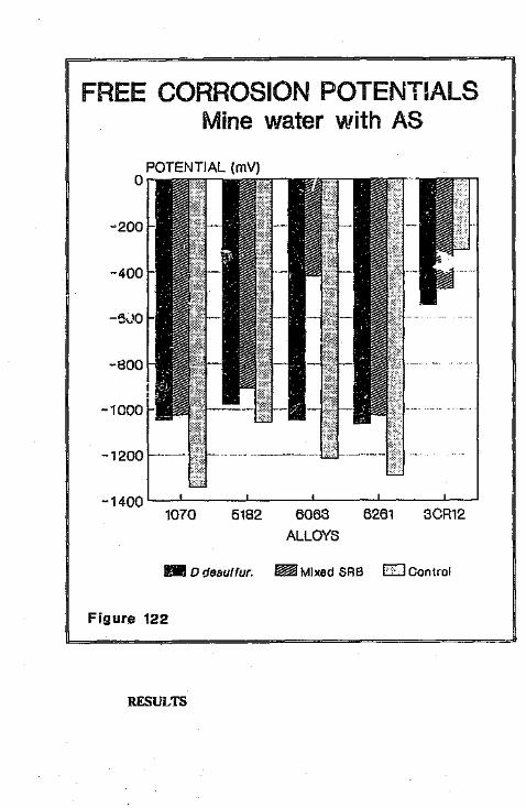
FREE CORROSION POTENTIALS lMine water with AS
1070 5182 6063ALLOYS
6261 3CR12
_ 0 desuitur. ~ Mixed SRB E:J Control
Figure 122
~====================================~
RESULTS

r FREE CORROSION POTENTIALSMine water with FAS
POTENTIAL (mV)o
~ -200!!
-400
-600
-800
-1000
5182 6063ALLOYS
6261 30R121070
l1li D. desultur. ~ Mixed SR3 [2J Control
Figure 123
113

r FREE CORROSION POTENTIALS\\ Mine water with AS
POTENTIAL (mV)o
-200
-400
-600
-800
-1000
-1400 '--"----'-----'--- ---....__~---'------'5182 6068 6261 8CR12
ALLOYS1070
_ Didesuitur. ~Mlxed SRS ElControl
Figure 122~======~~=-~=-=-======================:d
RESULTS
FREE CORROSION POTENTfALSMine water with FAS
-200
-400
-600
-800
-1000
-1200 '----'- __ .l.-_--'- __ __,____ .!-_.
1070 5182 6063 6261 3CR12ALLOYS
mD. desuttur. ~ Mixed SRS D Control
Figure 123
113

I~FREE CORROSION POTENTIALSI Medium with AS
POTENTIAL (mV)o
-20(.\
-400
-600
-800
-100()
1070 5182 6068 6261 8CR12ALLOYS
_ o.desutnn. ~ Mixed SRS E.B Control
Figure 124
RESULTS

FREE CORROSION POTENTIALSMedium with FAS
POTENTIAL (mV)o
-200
-400
-600
-80!)
-1000
-1200
1070 5182 6063 6261 3CR12ALLOYS
_ p.desuttur. ~ Mixed SRB c::J Oontrol
Figure 126=----
114

FREE CORROSION POTENTIALSlMine water '
POTENTIAL (mV)o
-600
Passive ranges of the alloys in mine water are presented in Figs. 127 and 128. In mine waters
containing AS, the passive range decreased in bacterial cultures for all alloys except the 5182 in the
D'.desulfuricans culture. This latter case can be explained by the shape of the pitting curve (Fig. 117)
where it can be seen that the imperfect passive range (Ep _-Ecorr) was greater for the bacterial cul-
ture than for the sterile control. However, the perfect passive range (Epp - Ecorr) Was decreased in
bacterial cultures. In the case of 3CRI2, the active peak formed in the bacterial cultures (Fig. 119)
caused a decrease in the passive range. Generally in mine water with FAS, the aluminium alloys
~xposed to bacterial cultures exhibited a larger passive range than the sterile controls, This could
be due to the passivating effect of the FeS layer. An exception was found for the i07Q alloy where
the bact ...ria decreased the passive range, This is the least alloyed of the aluminium samples and was
possibly unable to form a stable protective passive film, The passive range of the 3CR 12 was de-
creased by the SRB cultures.
RESULTS
-200
-400
-800
-1000
-1200
-1400~~--~~~----~------~----~--~5182 6063 6261
ALLOY-S1070 3CR12
- Pseudomonas ~ Control
Figure 126
115

PASSIVE RANGESMine water with AS
1070 5182 6063 6261 3CR12ALLOYS
l1li o.aeeuttur. ~ MIxed 8"lB Eill Control[I Figure 12::7L_
RESULTS

PASSIVE RANGESMine water with FAS
5182 6063A'LOYS
6261 3CR121070
_ o.desuttur. ~ Mixed SRB I22J Oontrol
Figure 128
Jl6

PASSIVE RANGESMedium with AS
PASSIVE RANGE (mV)1600r-~------------~------------~
1000
_ o.aesuttur. ~ Mixed SRB EZJ Control
I II'·Lure 129 .
800
600
400
200
o1070 5182 6063 6261 3CR12
ALLOYS
RESULTS

r PASSIVE RANGESMedium with FAS
1070 5182 6063 6261ALLOYS
l1li o.aesottur. ~ Mixed SRB [E]Control
Figure 130
117

PASSIVE RANGESMine water with AS
PASSIVE RANGE (mV)1400
800
800
.aO200
01070 5182 6063 6261 3CR12
ALLOYS
_ D.desulfur. ~ Mixed SRB EJ Control
Figure 127
RESULTS
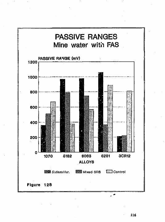
PASSIVE RANGESMine water wit;, FAS
1070 5182 6063 62.01 3CR12ALLOYS
~ o.aeeuttur. ~ Mixed SRB E2J Oontrol
l=igure 128
116

PASS~VERANGESMedium with AS
1070 5182 6063 6261 3CR12ALLOYS
_ D.desulfur. ~ Mixed BRS W ocntrct
Figure 129
RESULTS
PASSIVE RANGESMedium with FAS
1070 5182 6063ALLOYS
6261
_ D.desulfur. ~ Mixed SRS CZJ G!mlrol
Figure 130
117
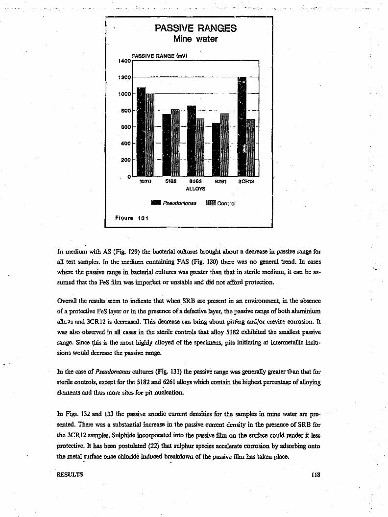
In medium with AS (Fig. r29) the bacterial cultures brought about a decrease in passive range for
all test samples. In the medium containing FAS (Fig. 130) there was no general trend. In cases
where the passive range in bacterial cultures Was greater than that in sterile medium, it can be as-
sumed that the FeS film was imperfect or unstable and did not afford protection.
PASSIVE RANGESMine water
PASSIVE RANGE (mV)1400r---------------------------------~
400
200
5182 6063
ALLOYS1070 6261 3CR17.
Overall the results seem to indicate that when SRB are present in an environment, in the absence
of a protective FeS layer or in the presence of a defective layer, the passive range of both aluminium
alk.vs and 3CR12 is decreased. This decrease can bring about pitting and/or crevice. corrosion. It
was also observed in all cases in the sterile controls that alloy 5182 exhibited the smallest passive
range. Since this is the most highly alloyed of the specimens, pits initiating at intermetallic inclu-
siena would decrease the passive range.
_ Pseudomonas ~ Control
Figure 131
In the case of Pseudomonas cultures (Fig. 131) the passive range was generally greater than that for
sterile controls, except for tho 5182 and 6261 alloys which contain the highest percentage of alloying
elements and thus more sites for pit nucleation.
In Figs. 132 and 133 the passive anodic current densities for the samples in mine water ate pre-
sented. There was a substantial increase in the passive current density in the presence of SRB for
the 3CR12 samples. Sulphide incorporated into the passive film on the surface could render it less
protective. It has been postulated (22) that sulphur species accelerate corrosion by adsorbing onto
the metal surface once chloride induced breakdown of the passive film has taken place.
RESULTS IlS

PASSIVE CURRENT DENSITIESMine water with AS
5182 6261 3CR12
In the case of aluminium alloys the higher passive current densities for controls as compai ed to test
samples suggests that the aluminium oxide protective layer was more stable in the bacterial cultures
and thus afforded protection. Generally inmine water with PAS there Was D slightly higher passive
current density for samples exposed to SRB, once again suggesting the interference of PeS in the
passive Iilm formation.
1070 6063
ALLOYS
[I _ - o.oesiutur.
~2
~ Mixed SRB [7J Control
In medium (Figs. 134 and 135) the passive current density was greatly increased in the presence of
SRB for the 3CR12 specimens. The same general trend as that in mine water was followed by the
aluminium alloys.
The aluminium alloys in Pseudomonas cultures (Fig. 136) exhibited larger passive current densities
than the sterile controls suggesting that a stable passive HIm was formed in the presence of the
bacteria.
RESULTS 119

PASSIVE CURRENT DENSITIESMine water with FAS
107('/ 5182 6063 6261 3CR12ALLOYS
.. D.desul fur. ~ Mixed SRB I> >IOor,trol
Figure 133
RESULTS
PASSIVE CURRENT DENS~TIESMedium with AS
PASSIVE CURRENT DENSITY (uA/om2)200~--------------·------------~
o1070 5182 6063 6261 3CR12
ALLOYS
_ D.desu/tur. ~ Mixed SRB I i IOontrol
Figure 134
120

PASSIVE CURRENT DENSITIESMedium with FAS
1070 5182 6063ALLOYS
6261 3CR12
l1li o.aesuui«. ~ Mixed SRB k lOontrol
Figure 135
RESULTS

PASSIVE CURRENT DENSITIESMine water
5182 60$3ALLOYS
6261 3CR121070
_ Pseudomonas ~ Oontrol
Figure 136
121

4.4.3 Tafel extrapolation
Tafel plots for all alloys in bacterial cultures and sterile solution in both medium and mine water
were carried out. There was no significant change in the Tafel slopes of all specimens exposed to
bacterial cultures in mine water compared to those in the sterile test waters.
In the medium, however, the 3CR12 specimens in. D. desulfuricans cultures showed a significant
increase in the cathodic slope (196 mv/decade) compared to the control (40 mv/decade). In the
mixed SRB culture, the increase WaS negligible. In the case of mild steel, there Was a significant
increase in cathodic slope both inD. desulfuricans and mixed SRB cultures (46- and 56 mv/decade
respectively) compared to the control (19 my/decade). These results indicate that the corrosion
system was possibly under cathodic control.
In the case of the aluminium alloys, there was no significant change in either cathodic or anodic
Tafel slopes compared. to the control.
4.5 ELECTROCHEMICAL TESTS - FLOW CONDITIONS
4.5.1 Cyclic polarization
Pitting scans were conducted for aluminium alloys in sterile mine water and then in mine water
containing bacteria. Two different conditions were tested viz. a scan after 1-3 hours stabilization,
and a scan after 3 days stabilization. All scans were reversed at a current density of 100pA/cm2 •
Figs. 137 and 138 show typical curves for alloys under both sterile and test conditions. Overall, the
passive range was greater for the control samples as compared with the test samples. In both cases,
however, the pits f.iled to repassivate as indicated hy the failure of the return scan to crors the
forward scan.
RESULTS 122

/>-0.601 I--+--1-11-+-1----+----I---+-----1I--1-+-1 -11-t-1-111-----l1
789 2 3459799
10-5 10-4
0.,,[">'-' -0.15-1-...Ja:HI-Z -O.SOWI-ao,
-0.45
bacter'ia....······..···0 cont 1"0 I
••••• O .. • ....... !brf"........ 0'"
J Q••~b •~ AI"o ,,_'I eI .0fi . o·o !Jg 1"""i 0
Figure 137: Pitting curve of alloy 5182 (3 hrs)
CURRENT DENSITY CA/cm2)
..
:-° e- 00
.,.••'0
~ .! ~o 0A b
tJ'OP
0'"a~oo
o '20.00 I- i E'"-0.40 1-1 -I-lg_\+1-!-'+--I'1""'~='=:.:.-----tI--;---t-....,_1 -1-1 ·.....Ir-~-F1-f-----r.--I
1.20
>'-' 0.80-
I-Z 0.40 rWI-a0...
A-----A b a c t e r- i a... ••.. ••...... 0 c o n t r-o I
9700 2., 50700 2
10-5 to-4CURRENT DENSITY CA/cm2)
Figure 1:38. Pitting curve of alloy 1070 (3 days)
RESULTS 123

Under flow conditions the effect of the bacteria on the metal takes longer to manifest itself than
would he the case for a sample exposed to a vigorously growing laboratory culture. This was con-
firmed by examination of the immersion samples as mentioned. previously. Thus in comparing the
Ecorr values, passive ranges and passive current densities of control and test samples, the results
may not be a true reflection of the situation ie. it is difficul, to ascertain whether the bacteria are
exerting an influence or whether the difference is due to the slight difference inwater composition.
Figs. 139 - 144 show the free corrosion potential, passive ranges and passive current densities for
the alloys inmine water after different periods of stabilisation. In all cases it can be seen that with
time there was an enoblement of ECOlT values, an increase in passive range and a decrease in passive
current density for all alloys both in sterile mine water and inmine water containing bacteria. These
results suggest the buildup of a protective passive layer with time. However, as seen by the shapes
of the polarization curves, once pits have formed they are unable to repassivate, This could be
brought about when eventually the developing biofilm would cause the protective film to rupture,
thereby promoting corrosion.
RESULTS
FREE CORROSION POTENTIALSMine water flow loop (1-3 hrs)
POTENTIAL (mV)o
-100
-200
-300
-500t---._--
-600~~~------L_------L_ .L-~1070 5182 6063
ALLOYS6261
.. Bacteria ~~ Control
Figure 139
~======================== ,========~124

FREE CORROSION POTENTIALS, Mine water flow loop (3 days)
POTENTIAL (mV)o
-100
-200
-300
-500~~------J~----~----~--~5182 6063
AllOYS1070 6261
.. Bacteria ~ Control
Figure 140
RESULTS
PASSIVERANGE;-- lMine water flow loop (1-3hrs)
5182 6060AllOYS
62611070
IIIBacteria ~ Oontrol
Figure 141
125

1~=========="===Ba=o=te=rla===~===co=n=tr=OI I'_ Figure 142 ~
PASSIVE RANGESMine water flow loop (3 days)
PASSIVE RANGE (mV)1400~-------------------------~
1200
1000
800
600
400
200
o1070 5182 62616063
ALLOYS
RESULTS
PASSIVE CURRENT DENSITIESMine water flow loop (1~3 hrs)
51132 6063 62611070ALLOYS
_ Baoterla ~ Oontrol
Figure 143
126
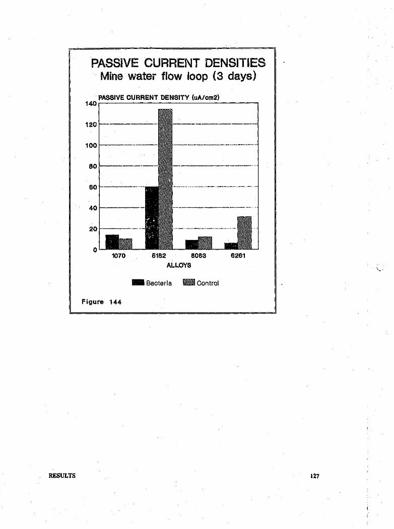
RESULTS
PASSiVE CURRENT DENSITIEStv1inewater flow loop (3 days)
PASSIVE CURRENT DENSITY (uAlcm2)140~--~~--------------------.
80 ;--------".--- ...
401-------",""
o5182 6063
ALLOYS62611070
.. Baoterla ~ Oontrol
Figure 144
127

5.0 DISCUSSION
.5.1 Mine Survey
The adverse corrosion effects of micro-organisms in many industrial applications, as borne out by
corrosion and biofilming leading to loss of essential heat transfer, decreased now rates, product
10(j",~"or deterioration, increased maintenance requirements etc, are well documented. In addition,
the detrn., ~ntal roles that SRB play in these activities has been widely studied. These organisms are
ubiquitous and are found in habitats ranging from fresh and sea water, to oil wells and cutting
emulsions. It was therefore not surprising that these organisms were found in abundance on in situ
exposed corrosion test coupons in mine waters. The presence of fungal masses and moulds on alloy
surfaces most certainly provided ideal anaerobic conditions for t~e growth of SRB. The
Pseudomonas spp. also play an important role in biofilm formation. These organisms colonize the
fungal mats, producing a slime which aids in creating anaerobic niches within the biofilms.
In a bacterial population structure study of water cooling systems on various South African mines,
Cloete et al (95) found that Pseudomonas flourescens was the predominant bacterium encountered
in the majority of systems studied. This was followed by P. picketti, P. putida, P. stuzeri and
Chromobacter violaceum The dominant bacteria showed a wide temperature tolerance indicating
that they are able to grow and form biofilms in various sections of the plant. Unfortunately, the
study concentrated on aerobic organisms and thus the presence of SRB was not investigated. The
dominant presence of Pseudomonas spp., however, indicates that these organisms play an important
role in biofouling.
The results show clearly that microbial species are present on aluminium alloys in mine water where
they form adherent biofilms. In agreement with Hedrick et al (70), the type of attack found on the
AI alloys viz. intergranular corrosion, exfoliation and pitting is indicative of microbial involvement
in the corrosion process since a predominance of pitting was found to occur in the chemical cor-
rosion system.
5.2 IMMERSION TESTS - STATIC
5.2.1 Weight loss results
Results from total immersion tests under static conditions showed that the AI alloys, both in sterile
medium and in SRB cultures, underwent very little corrosion as measured by weight loss. The
values ranged from between 0,07.0,19 mg!cm2 for D.desulfuricans cultures, between 0,006-0,06
mgjcm2 for mixed SRB cultures and between 0,006-0,13 mgjcm2 for sterile controls.
DISCUSSION 128

Weight losses on 3CR12 samples, carried out for comparative purposes, were also low, both inbacterial cultures (0,66mg/cm2 for mixed SRB cultures and 1,17 mg/crn 2 for Ir.desulfuricans cul-
tures) and in sterile medium (0,5 mg/cm2). As expected, mild steel specimens underwent more
corrosion with the largest weight loss being 2,7mg/cm2 in D'.desuulfuricans cultures. Tills figure did
not differ significantly from that for the control (2,2 mg/cm2). This latter result agrees with results
from Mara & Williams (96) and Ringas (93) who found that difference in weight loss between mild
steel coupons in sterile medium and bacterial cultures did not vary much. They attributed this to
the formation of a tightly adherent PeS film which was somewhat protective and provided resistance
polarization. This explanation could also account for low weight losses of the 3CRl2 coupons.
Weight loss results from immersion tests in mine water shewed that this was a far more aggressive
environment. This was especially noticeable for the aluminium alloys in sterile deaerated mine wa-
ter. The 5182 alloy showed a massive weight loss of 82,3 mg!cm2• On removal from the flasks, the
coupons were covered by a thick white voluminous mass which was soapy to the touch. The pH
of the medium was foi.nd to be 9,2. This would explain the large weight loss since at this pH the
oxide film is no longer stable or protective and would thus allow for generalized corrosion. The
weight losses for the alloys in SRB cultures were reasonably low. Although colonization of the
alloys did take place, this was not as prolific as growth in the nutritive medium. MPN counts in fact
revealed lower bacterial numbers. This would be expected, since the mine water would not cot tCiin
many essential nutrients in high enough concentrations.
The mild steel specimens showed greater weight loss in bacterial cultures than in sterile mine water.
The surface of this alloy was perhaps able to absorb essential nutrients more easily and hence attract
more bacteria. The reason for low weight losses in the 3CR12 specimens could be attributed to an
adherent PeS layer which afforded protection. On the mild steel specimen, on the other hand, this
layer-may have cracked due to bacterial growth and thus promoted corrosion.
The Pseudomonas cultures both in medium and in mine water definitely had some effect on the
Al alloys as seen by the greater weight losses experienced by test samples compared to the controls.
TIllS was more noticeable in the mine water in which weight losses of between .6,26 and 7,90
mg/cm2 were recorded.
Pseudomonas species have been found to bring about corrosion of aluminium alloys. In immersion
tests with various microorganisms, including Piaerugirosa, Hedrick et al (69) found weight losses
of between 0,015 to 0,574% on alloy 7178 after QO days. Pseudomonas cultures were also found by
Blanchard and Goucher (85) to accelerate corrosion of alloy" 7075 and 2024. This was thought to
be due to large molecular weight molecules synthesised by the organisms. As mentioned previously,
Hedrick and coworkers (27, 69,71, 86) also formulated the hypothesis that the corrosion of AI al-
loys by aerobic microorganisms results from the removal of certain metallic atoms from the crystal
lattice of the alloy by extracellular enzyme activity. They found that Al alloys high in Mg and Zn
were more susceptible to corrosion by a mixed culture of Cresinae and Pseudomonas spp. than al-
loys with low Mg and Zn content. In the present tests the 5182 alloy, which has the highest Mg,
DISCUSSION 129

Mn and Zn content, showed the largest weight loss and was covered by large amounts of corrosion
product. This, and the fact that then: was greater weight loss in the mine water (which has far fewer
nutrients) than in the medium, could support the theory that the microorganisms are obtaining their
metal requirements from the alloy. Plate counts revealed that the mine water supported a relatively
large Pseudomonas population, and the findings of Cloe: : et al (95) as mentioned previously would
tend to support this.
The low weight losses recorded for the 3CRl2 specimens in both the mine water and medium in-
dicated that the Pseudomonas cultures had little effect on this alloy. The mild steel specimens
underwent higher weight losses in the Pseudomonas cultures compared with weight loss results after
exposure to SRB. However this could be attributed to the lack of a protective FeS layer as well
as to the aeration of the medium which promotes corrosion.
Since pitting attack was the more prevalent form of corrosion on the aluminiun alloys and can re-
sult in catastrophic corrosion with only a small amount of weight loss, the alloys cannot be rated
by weight loss criteria alone. The nature of the attack must be studiee. For this reason, SEM ex-
aminations were performed, the results of which could explain the low weight loss results obtained.
5.3 IMMER.SION TESTS .-FLOW CONDITIONS
5.3.1 Weight loss results
Gen ..-ally, weight losses under flow conditions were greater than those in the static immersion tests.
This result was also obtained by Buchan (58) in a study of ',.' -ninium alloys in two different mine
waters. The difference in mass loss results between the sterile "d.ter and that containing bacteria can
be explained by the fact that the waters, though fairly similar, did vary with respect to pH and total
dissolved solids.
Colonization of the alloys was sparse even though bacteria v, ere present in the water, as borne out
by regular plate counts and the presence of the beginning of slime formation on the inside of the
plastic tubes housing the spec+nens, It has been found (97) that transport of cells and nutrients to
a surface takes place by Brownian diffusion along a concentration gradient in-the absence of flow.
An increase in flow velocity decreases the thickness of the boundary layer across which diffusion
takes place, and with the onset of turbulence, turbulent diffusion very substantially increases the
mass transport to the substrate wall. Thus the transport of cells, abiotic particles and potential nu-
trients to the surface is increased. Under these conditions, rapid adhesion and biofilm development
should be favoured. However, a high velocity also increases shear forces over the surface which
may reduce the overall efficiency of microbial attachment processes, and the increased shear stress
at the surface will tend to remove attached biomass.
DISCUSSION 130

The failure of bacterial attachment to the alloy surfaces could be explained by the above. The
coupons were positioned in the centre of the pipe, an area of turbulent flow. This would also ex-
plain the initiation of slime formation on the pipe walls where, due to the boundary layer, shear
stresses Were minimal, thus allowing for bacterial adhesion.
Thus any weight losses were probably due to the corrosive action of the mine water alone. In the
case of the 6261 alloy, however, the presence of the scale layer and bacterial cells, would tend to
suggest some microbial involvement. The extrusion marks would have presented a fairly rough
surface which, under flow conditions, would increase the amount of turbulence and thus the mass
transport of cells and nutrients to the surface.
5.4 SEM OBSERVATIONS
As expected colonization of the alloy surfaces in medium was well developed, as this represented
an ideal situation in which nutrients were in plentiful supply. The type of colonization ie. formation
of tubercles covered by bacteria, is similar to that found on ferrous metals by other workers. Under
these conditions, both the Ir.desuifuricans and the mixed SRB cultures formed healthy biofilms and
were able to bring about corrosion in the form of random pitting and intergranular attack. In the
case of the 5182 alloy, pitting seemed to initiate preferentially at inclusions. This type of corrosion
would explain the low weight loss results obtained.
In mine waters, colonization took place to a much lesser extent. This Was especially so under flow
conditions as has been explained above. The situation. in the static mine water tests could have been
due to the low concentrations of essential nutrients in the Water. The volume of water to surface
area of specimens was 1110tparticularly great and changes with sterile stocks of mine water were only
made twice a week. This would also explain why colonization was more prolific in the mixed SRB
culture. Since this culture contained a variety or' organisms, including facultative anaerobes, the
SRB within this consortium could obtain essential nutrients and environmental protection from. the
microbial community. In contrast, the Ir.desulfuricans culture could only utilize the nutrients
present in the mine water.
t he extent of the corrosive attack seen on aluminium alloys in mine waters as compared to those
m the rr limn were distinctly different. In the former, pits were initiated in most cases at inclusions.
Particles of intermetallic phases are reported to be the common sites for pit nucleation in
aluminium and its alloys with other elements (98). Pits Were found to nucleate in a 5-series alloy
on particles of intermetallic compounds of the following approximate composition.- (Cr, Fe,
Mn)A16• The second phases and precipitates are often anodic to the primary phase or solid sol-
ution and thus are points of preferential attack. The alloying clements may also introduce inho-
mogeneities to the oxide film sud so decrease its efficacy as a barrier to further oxidation (98).
DISCUSSION 131 cI

The 1070 alloy, which is a commercial purity aluminium containing less than 1% alloying elements,
showed less pitting damage .nan the other alloys. The corrosion manifested itself mainly as selective
phase dissolution.
In cultures of mixed SRB, and more so in Pseudomonas cultures, the 5182 alloy seemed to suffer
selective attack in the form of pitting at grain boundaries. Different impurities may segregate to the
grain boundaries in metals and this is thought to be the main reason for the higher reactivity of grain
boundaries relative to the grains. Susceptibility of grain boundaries to pitting is due to the presenceof segregated impurities and/or precipitated particles (98). The 5182 alloy is an Al-Mg alloy in
which the Mg2Al precipitates are anodic to the solid solution and will thus undergo preferential
corrosion. The addition of Si increases the solution potential to nearer that of pure aluminium and
with proper control random precipitation should reduce selective attack at grain boundaries. In
these tests however, pits were initiated at Mg2AI precipitates as well as at intermetallic compounds
containing Fe and Mn, Buchan (58) also reported selective attack of precipitates at grain boundries
in a 5251 aluminium alloy in mine water.
The 6-series Al-Mg-Si alloys may show preferential attack at particles containing Mg and Si whichare not in the ratio of 2:1 respectively. Fe and Mn precipitates also seemed to adversely affect the
pitting in both SRB and Pseudomonas cultures.
The ferrous alloys did not seem to be affected by microstructure, a result borne out by Mara and
Williams (96) in the corrosion of mild steel by SRB.
Another factor to be taken into consideration in mine waters is the presence of Cu ions. The pres-
ence of a small number of Cu ions in fresh water has been found to stimulate initiation of pitting
by depositing a layer of copper particles on FeAl3 making them much more efficient as cathodes
for corrosion processes (98). The water analysis indicated that copper was present in the mine wa-
ters used and the presence of a copper layer on the 6261 alloy was cornfirmed by EDAX analysts.
Thus it seems that mine waters contaminated with bacteria present an aggressive environment for
aluminium alloys leading to pitting at alloying inclusions (which was especially marked in the 5182alloy), dissolution of secondary phases and intergranular attack. The aggressiveness of mine waters
towards Al alloys was also reported by Buchan (58) and McEwan (67).
5.5 ELECTROCHEMICAL TESTS
Tests were carried out in both mine water and nutritive medium and though the former solution
was more aggressive, the behaviour of the alloys in both solutions followed a similar trend. The
different redox poising chemicals used viz. AS and FAS affected the properties of the solutions by
introducing Fe ions in the latter case which could then complex, with the sulphide formed tl.roughthe acti.on of SRB.
DISCUSSION 132

Results from tests on 3CR12 correlated well with results of Ringas (93). The alloy passivated both
in sterile medium and mine water containing AS as it did in these solutions containing FAS. In the
latter case, however, the passive ranges were lower. Scans performed in SRB cultures showed a
marked difference exhibiting a more active free corrosion potential, a reduced passive range, an ac-
tive peak, hysteresis in the return scan and a greatly increased passive current density. These results
indicate that these bacteria adversely affected the corrosion resistance of this alloy by decreasing the
c evice corrosion resistance (as indicated by the amount of hysteresis and the formation of an active
peak), and by decreasing the potentials of safe operation through incorporation of SUlphide in the
passive film which makes it less protective. In the presence of PAS, the formation of FeS on the
alloy surface had the effect of either aiding passivation when it was a tightly adherent film, or pro-
moting corrosion when it occured as a loose bulky mass. The Ecorr values became more active due
to the action of H2 S formed by the SRB.
The performance of the aluminium alloys was not as clearcut. Pitting scans in both the sterile mine
water and medium containing AS, showed that the aluminium alloys passivated and the reverse
scans returned to the left of the forward scans indicating that spontaneous repassivation took place. -
In SRB cultures in solutions containing AS the effect was to decrease the passive range and ad-
versely affect the crevice corrosion resistance of the alloys. Although the passive current density was
low for both control and test samples, alloys exposed to bacterial cultures showed decreased values.
In addition, the bacteria shifted the Ecorr values to more noble potentials, compared to the sterile
controls. It would thus appear that the bacteria enhanced the conditions for passivity in the
aluminium alloys. It is considered likely that the above effects were related to corrosion product
build - up (through bacterial action), which functioned as a temporary diffusion barrier and slowed
down the corrosion process. From the EDAX analysis, the formation of an aluminium sulphide
layer, which could function as a diffusion barrier, was apparent. Such layers arc, however, only ef-
fective if they are in the uncracked condition. Should flaws occur, localised penetration would be
expected to take place. Under industrial conditions, cracking of the surface layers would be more
likely than in the st~gnant, non-turbulent, non-abrasive laboratory experiments.
It has been shown that incorporation of sulphide In the passive film renders it less protective, delays
'repassivation and can increase the likelihood of crevice attack (99). In this case the sulphide may
have influenced the crevice corrosion resistance of the alloys, though the high' sulphate content of
the solution (especially that in mine water) helped form a more stable passive film.
The addition of FAS to the mine water and medium did not affect the behaviour of the sterile
controls. In SRB cultures, however, there was a marked effect. The free corrosion potentials became
more active, the passive current densities increased inmost cases and ~he perfect passive ranges were
decreased. In addition the crevice corrosion resistance was adversely affected. These findings suggest
that the presence of the FeS is the major factor affecting the corrosion resistance of the alloys. The
increase in passive current density and the decrease of the perfect passive range in the presence of
FeS suggests that this interfered with the passive film formation.
DISCUSSION 133

The involvement of H2 S may also be considered here. It has been postulated that H2 S may play
a role in corrosion. As lIS- ion concentration increases in a crevice, H + ions migrate to the crevice
in order to achieve charge neutrality, thereby increasing the acidity locally (93). In electrochemical
tests, the test cell was adapted to allow for deaeration of the headspace alone thus resulting in
minimal loss of H2 S from the medium. Although Ecorr values became more active in the presence
of FAS, thus suggesting H2 S involvement, in solutions containing AS there was no such effect.
This suggests that FeS is exerting the main influence. This could be due to the complex acting as
local cathodes on the aluminium surface thereby increasing its susceptibility to pitting.
These findings indicate that in mine water containing SRB, both aluminium alloys and 3CRl2
would suffer accelerated corrosion due to the presence of sulphide (reduced from SUlphate in the
mine water by SRB) and Fe (due to oxidation of pyrite).
In Pseudomonas cultures, bacteria had the effect of decreasing the perfect passive range and ad-
versely affecting the crevice corrosion resistance of the aluminium alloys as indicated by the for-
mation of an active peak and an inability for repassivation,
Results from Tafel extrapolations for all Al alloys in both bacterial cultur. 1 •~S in-
dicated no significant change in the Tafel slopes of scans performed or 11. .rimens exposed to
bacteria compared to those in sterile medium. However, in the C[lSC of 3CI,12 and mild steel spec-
imens which were exposed to flourishing SRB en res in nutrativc medium, an increase in the
cathodic Tafel slope in the bacterial cultures suggested that cathodic depolarization was in fact
taking place. This was not the case in SRB cultures in mine water where th~ bacterial umbers were
possibly too low to exert any effect.
In the case of the AI alloys, the electrochemical corrosion test results tend to suggest that the pres-
ence of bacterial species adversely affect their corrosion resistance by interfering indirectly with
passive film formation, as well as by decreasing their crevice corrosion resistance and ability for pit
repassivation. The importance of FeS in the corrosion process was also ascertained. The theory of
microbial utilisation of alloying elements could well apply in the case of Pseudomonas cultures. The
mode of corrosion by SRB is not as clear, but cathodic dcpolarisation by H2 S and F:!S may occur.
5.6 RANKING OF AL ALLOYS
The relative performance of the alloys under various conditions in the test waters was determined
by ranking them according to three different test result criteria, viz. weight loss (WL), general cor-
rosion rate (CR) and passive range (PR.). The alloy showing the least weight loss, the lowest cor-
rosion rate and the highest passive range was given a value of 1, while the worst performer received
a rating of 4. ThF: ratings for the tests were added together and the alloy with the lowest total was
judged the best performer, It must be stressed, however, that this is a fairly subjective approach and
is intended to serve only as a very rough guide. The results are given below.
DISCUSSION 134

TableS. Ranking of alloys
Alloys WL(mg/cm2 ) CR(mpy) PR. TOTAL
D .desulfuricans 1070 2 I 4 7
5182 4 3 3 106063 3 4 2 96261 1 2 1 4
SRB(M) 1070 2 3 3 85182 1 1 1 3
6063 3 2 2 7
6261 4 4 4 12
SRB(C) 1070 3 4 2 95182 4 1 4 96063 2 2 3 7
6261 1 3 1 5
Pseudomonas 1070 2 1 1 45182 4 4 3 11
6063 1 2 2 56261 3 3 4 10
Pseudc monas(C) 1070 4 2 1 7
5182 3 1 3 7
6063 1 4 2 7
6261 3 3 4 10,
Overall, the 5182 alloy was the worst performer. This could be attributed to the preferential attackof intermetallic inclusions, especially since the 5182 alloy has the highest percentage of alloying d-ements of all the Al alloys tested. 10. the case of the Pseudomonas culture, the ranking followedexactly the trend of amounts of alloying additions with 107(:)(11commercial purity alloy) sufferingthe least corrosion and the 5182 alloy the most.
DISCUSSION 135

6.0 CONCLUSIONS
G From the mine survey, ins evident that microbes are present in mine waters, are able tocolonize the aluminium alloy surfaces and seem to. bring about pitting and intergranular cor-rosion. Furthermore the presence of sulphur species at the base of the pits and the absenceof chlorides suggest microbial influence.
o Immersion test results indicate that in situations where nutrients are in plentiful supply,microbes proliferate on aluminium surfaces and bring about pitting and intergranular corro-sion.
o Under conditions where essential nutrients are in short supply, biofilm development will beslow. However, once a complex microbial consortium has developed, the biofilm will assist intrapping and concentrating nutrients as well as givingenvironmental protection to detrimentalorganism, which would then almost certainly bring about aluminium corrosion.
o Anodizing and conversion coating At alloys may temporarily protect the surfaces from be-coming colonized by microorganisms, Any defect or damage to the coating will immediatelypromote colonization.
G In the presence of SRn the integrity and protective nature of the passive films on aluminiumalloy surfaces tested were adversely affected. The crevice corrosion resistance and pitrepassivation abilities of the alloys were decreased. This led to the formation of pits andintergranular attack. The involvement of FeS in the corrosion process was established and itis postulated that this may act as a cathodic depolariser.
• The mode of corrosion of AI alloys by Pseudomonas spp, seems to be due to utilization ofalloying elements by the bacteria.
• The aluminium alloys with the most alloying additions underwent more corrosion due topreferential pitting attack at intermetallic inclusions.
CONCLUSIONS 136

7.0 RECOMMENDATIONS
• The study of biofilms in environments that resemble in situ situations as closely as possible
can produce valuable information. The use of a Robbins Device (100) in cooling water sys-
tems on mines to study natural populations and type of corrosive attack should be carried out.
.. Further work should be carried out on methods of altering the A1 alloy surfaces in order to
prevent microbial attaclunent.
• Further investigations to determine the mechanism of microbial corrosion are needed.
• Due to severe pitting, the alloys tested would not be recommended for use inmine waters.
RECO!\1MENDATIONS 137
8.0 REFERENCES
1. Lutey, R. Microbiological Corrosion, reprinted from the International Corrosion Forum, Pa-
per 30, Mar 1980.
2. Hughes, L. Microbiological corrosion. Is it bugging you? Buckman Laboratories (PTy) ltd,
Johannesburg, May 1986.
3. Costello, I.A. The corrosion of metals by rnicroorganisms- a literature survey, Int. Biodetn.
Bull, Vol. 5, 1969, pp 101-118.
4. Iverson, W.P. Biological corrosion, Advances in Corrosion Science and Technology, Vol. 2,1972, pp 1-42.
5. Miller, J.D.A. and King, R.A. Biodeterioration of metals. In: Gilbert and Lovelock, eds
Microbial aspects of the deterioration of materials, London, Applied Science Publ., 1975.
6. Tatnall, R.E. Fundamentals of bacteria induced corrosion, Materials Performance, Vol. 20,
1981, pp 32-38.
7. Hamilton, W.A. Sulphate-reducing bacteria and anaerobic corrosion, Ann. Rev. l\licrobiol.
Vol. 39, 1985, pp 195:217.
8. King, R.A. An outline of 150 man-years of microbial corrosion studies at UMIST, Corrosion
87, Paper no.368, 1987, pp 1-15.
9. Iverson, W.P. Microbial corrosion of metals, Advances in applied microbiology, Vol. 32, 1987,
pp 1-16.
10. Gaines, R.B. Bacterial activity as a corrosive influence in the soil, J. Ind. Eng. Chern, Vol 2,
1910.
11. Postgate, I.R. Economic importance of sulphur bacteria, Phil. Trans. R. Soc. Lond., Vol. 298,
1982, pp 583-600.
12. Tatnall, R.E., Stanton, K.M. and Ebersole, R.C. Methods of testing for the presence of
sulphate reducing bacteria, Corrosion 88, Paper no. 88, Mar 88, pp 21-25.
13. King, R.A. and Miller, I.D.A. On the SUlphate reducing bacteria and their corrosive activities,
Paper presented at Microbios 88, Johannesburg, 1988.
14. Costerton, l.W. and Lashen, E.S. The inherent biocide resistance of corrosion-causing biofilm
bacteria, Corrosion 83, Paper no. 246, 1986, pp 1-11.
REFERENCES 138

IS. Pope, D.H. et al. Microbiologically influenced corrosion of industrial alloys, Corrosion 83,
Paperno. 247, 1983, pp 1-14.
16. Costerton, J.W. et al. Bacterial biofilms in nature and disease, Ann. Rev. Mlerobiol., Vol. 41,
1987, pp 415-464.
17. von Holy, A. Microbiological corrosion, Paper Southern Africa, Sept/Oct 1985, pp 12 and
16.
18. Iverson W.P. Anaerobic corrosion mechanisms, Corrosion 83, Paper no. 243, 1983, pp 1-7.
19. Booth, G.H., Shinn, P.M. and Wakerley, D.S. The influence of various strains of actively
growing sulphate reducing bacteria on the anaerobic corrosion of mild steel, Cong.lnt. Cor.
Marine, Salissures, Cannes, 1964, pp 363-371.
20. Mara, D.O. and Williams, D.S.A. The mechanism of SUlphide corrosion by sulphate reducing
bacteria. In: Walters, A.M. ed, Biodeterioration of materials, Vol 2, London, Applied science
Pub!., 1976.
21. Booth, G.H., Elford, L. and Wakerley, D.S. Corrosion of mild steel by sulphate reducing
bacteria: an alternative mechanism, Br, Corros, J., Vol.3, 1968, pp 242-245.
22. Cragnolino, G. and Tuovinen, O.H. The" role of sulphate-reducing and sulphur-oxidizing
bacteria On localized corrosion, Corrosion 83, Paper no. 244, 1983, pp 1-26.
23. Weimar, P.J. et al. Effect of phosphate on the corrosion of carbon steel and on the composi-
tion of corrosion products in two-stage continuous cultures of Desulfovibrio desulfuricans
Appl, and En". Microbiol., Vol 54, 1988, pp 386-396.
L4. Schaschl, E. Elemental sulphur as a corrodent in deaerated neutral aqueous environments,
Materials Performance, Vo119, 1980, pp 9-12.
25. Bates, J.F. Materials Performance Vol 20, 1981, pp56.
26. Miller, J.D.A. Metals, In: Rose, A.I-1. ed, Economic microbiology 'Vol 6, Microbial
Biodeterloratlon, 1981, pp 150-202.
27. Hedrick, H.G. Microbial corrosion of aluminium, Materials Performance Vol. 9, 1970, pp
27-31.
28. Hamilton, W.A. Sulphate-reducing bacteria and the offshore oil industry, Trends in
biotechnology, Vol 1, 1983, pp 36-40.
REFERENCES 139

29. Hill, D.W., Reus.Bel. and Undesser, M.J. Control of microbiological related problems in the
Kaparuk river unit wa", flood, Corrosion 87, Paper no. 378, 1987, pp 1-16.
30. Littmann, E.S. Microbiologically influenced corrosion of oilfield producing well equipment,
Corrosion 87, Paper no. 372, 1987, pp 1·9.
31. Sanders, P.F. and Stott, 1.F.D. Assessment, monitoring and control of microbiological cor-
rosion hazards in offshore oil production systems, Corrosion 87, Paper no. 367, 1987, ppl-15.
32. Tatnall, R.E. Case histories: bacteria-induced corrosion, Corrosion 81, Paper no. 130, 198i,
pp 1-15.
33. Hill, E.C. Microbial infections in relation to corrosion during metal machining and deforma-
tion. In: Miller, J.D.A. ed, Microbial aspects of metallurgy, England, Medical and Technical
Publishing ce., 1970.
34. Bibb, M. and Hartmann, K.W. Bacterial corrosion, Proe. 4th South African International
Corrosion Conference, The South African Corrosion Institute, Johannesburg, 1985.
35. Honneysett, D.O., van den Bergh, W.D. and O'Brien, P.F. Microbiological corrosion control
in a cooling water system, Materials Performance Vol. 24, 1985, pp 34-39.
36. Pope, D.H., Soracco, R.J. and Wilde, B.W. Studies on biologically induced corrosion in heat
exchanger systems at the Savannah River Plant, Aiken, SC, Materials Performance, Vo1.21,
luI 1982, pp 43-50.
37. Puckorius, P,R. Massive utility condenser failure due to sulphide-producing bacteria, Corro-
sion 83, Paper no. 248, 1983, pp 1-7.
38. Kiefner, J F. and Biber, R.J. SCC, bacteria top items in pipe service failures, Oil and Gas ,:.,
Vol 20, Apr 1987, pp 70-75,
39. Bell, R.O. and Lim, C.K. Corrosion of mild and stainless steel by four tropical Desulfovibrio
desulfuricans strains, Can. J. Microbiol., Vol 27, 1981, pp 242-245.
40. Crombie, D.J., Moody, G.J. and Thomas, J.D.R. Corrosion of iron by sulfate-reducing bac-
teria, Chemistry and Industry, Vol 21, 1980, pp 500·504.
41. King, R.A., Miller, J.D.A. and Wakerley, D.S. Corrosion of mild steel in cultures of
sulphate-reducing bacteria: Effect of changing the soluble iron concentration during growth,
Hr. Corros, J., Vol. 8, 1973, pp 89-93.
42. Kobrin, G. Corrosion by microbiological organisms in natural waters, Materials
Performance, Vol IS, 1976.
REFEREl'Ii CE.,'\ 140

43. Gerchakov, S.M., Little, B.l. and Wagner, P. Probing microbiologically induced corrosion,
Corrosion, Vol. 42, 1986, pp 685-692.
44. Guillaume, I., Grimadeau, 1. and Valensi, G. Facteurs d'immunite et de corrosion du cuivre
dans un milieu marin bacterien, Corr, Science, Vol. 13, 1973, pp 85~96.
45. Guillaume, I. et al. Principaux facteurs d'immunite et de corrosion du nickel dans un milieu
bacterien, Corr. Science, Vol. 13, 1973, pp 97-103.
46. Characklis, W.G. et al, Influence of biofouling and biofouling control techniques on corrosion
of copper-nickel tubes, Corrosion 83, Paper no. 250, 1983, pp 1-19.
47. Elphick, 1.1. Microbial corrosion in aircraft fuel tanks. In: Microbial aspects of metallurgy,
ibid. 33.
~.J- . izovkina, T .B. et al. Influence of -nicroorganisms on corrosion of metals in the sea, trans-
latedfrom: Zashchlta Metallov, Vol. 21, 1985, pp 617-620.
49. Dexter, S.C. and Gao, G.Y. Effect of seawater biofilms on corrosion potential and oxygen
reduction of stainless steel, Corrosion 87, Paper no. 377, 1987, pp 1-11.
50. Mar, E.D., Scotto, V. and Mollica, A. Contribution to the discussion on localized corrosion
of stainless steels innatural sea water, Werkstoffe und Korroslon, Vol. 31, 1900, pp 2:::1-285.
51. Sanders; P.F. Biological aspects ofrnarine corrosion, Metals Society World, Dec 1983.
52. Schiffrin, 0.1. and de Sanchez, S.R. The effects of pollutants and bacterial microfouling on
the corrosion of copper base alloys in seawater, L.'·Tosion, Vol. 41, 1985, pp 31-38.
53. Scotu., V., di Cinto, R. and Marcenaro, G. The influence of marine aerobic microbiil filmOn stainless stcel corrosion behaviour, Corr. Science, Vol. 25, 1985, pp 185-l9·t
54. Pope, D.H. et al. Microbiologically influenced corrosion- a state-of-the-art-review, MTI Pub-
lication No. 13, Materials Technology Institute of the Chemical Process Inrl;····des Inc, 1986.
55. Salverezza, R.C., de Mele, A.P.L. and Videla, H.A. The U:;.; of pitting po .. ·, if) study the
microbial corrosion of 2024 Aluminium alloy, Int. Biodeterlor. Bull., Vol. 15, 1979, pp
125-135.
56. van Hom, K.R. ed, Aluminium Vol 1: Properties, Physical metallurgy and Phase diagrams,
Ohio, American Society for metals.
57. Malan, S.F. and Patterson, A,E. eds Introduction to Aluminium, 1st edition, Aluminium
Federation of South Africa, 1987.
REFERENCES 141

58. Buchan, A.J. Corrosion of aluminium alloys in static and recirculating mine waters, MSc the-
sis, University of the Witwatersrand, Johannesburg, 1988.
59. Zajic, J.E. Microbial Biogeochemistry, London, Academic Press, 1969.
60. Miller, R.N. et al Research program shows microorganisms cause corrosion in aircraft fuel
tanks, Materials Protection, Vol. 3, 1964, pp 60-67.
61. Boggs, W.A Changes in aircraft design, fabrication and finish techniques and maintenance
requirements dictated by microbe-infested jet-fuel sources, Proc, 25th Conf, Nat. Assoc.
Corros. Eng., NACE, Houston, Texas, 1970, pp 624-637.
62. Schmitt, C.R. Anomalous microbiological tuberculation ~'JJ.daluminium pitting corrosion-
case histories, Proc, International Conference on Biologically Induced Corrosion, Gaithersburg,
Maryland, 1985.
63. Videla, H.A. and de Mele, M.F.L. Microfouling of several metal surfaces in polluted sea water
and its relation with corrosion, Corrosion 87, Paper no. 365, 1987, pp 1-16.
64. Guillaume, I et al Conditions d'immunite et de corrosion de l'aluminium dans un milieu
bacterien doux et marin, Corr. Science, Vol. 14, 1974, pp 321-329.
65. Ulanovskii, I.B., Ledenev, AV. and Tolokneva, L.M. Influence of aerobic bacteria on cor-
rosion and cathodic protection of aluminium and alloy AMg6, Protection of metals (USSR),
Vol. 18, 1982, pp 199-201.
66. Willingham, C.A. and Quinby, H.L. Effects of hydrostatic pressures on anaerobic corrosion
of various metals and alloys by sulphate-reducing marine bacteria, Developments in Industrial
Microbiology Vol. 12, 1970, pp 278-284.
67. Me Ewan, J.J. Measurements of the corrosion rate of six aluminium alloys, phosphorus
dcoxidiscd copper and 3CR12 in a heat-exchanger circuit, Mintek, Report No. C 958M, 1988.
68. Tiller, AK. and Booth, G.H. Anaerobic corrosion of aluminium by sulphate-reducing bac-
teria, Corr. Science, Vol. 8, 1968, pp 549-555.
69. Hedrick, H.G. et al Selection of a microbiological corrosion system for studying effects on
structural aluminium alloys, Applied Microbiology, Vol. 12, 1964, pp 197-200.
70. Hedrick, H.G. et al Mechanisms of microbiological corrosion of aluminium alloys,
Electrochemical Technology, Vol 5, 1967, pp 75..77.
71. Hedrick, H.G., Reynolds, R.J. and Crum, M.G. Microbiological corrosion of aircraft metal
alloys, Developments in Industrial Microbiology, Vol. 10, 1969, pp 228-233.
REFERENCES 142

72. Salvarezza, R.C., de Mele, M.F.L. and Videla, H.A. Redox potential and the microbiological
corrosion of aluminium and its alloys in fuel/water systems, Br, Corros, J. Vol. 16, 1981, pp162-168.
73. Leiro, M.C. et a1 Microbiological corrosion of metallic alloys, Int. Congress of Metallic Cor-
rosion , Toronto, Jun 1984.
74. Iverson, W.P. A possible role for sulphate reducers in the corrosion of aluminium alloys,
Electrochemical Technology, Vol. 5, 1967, pp 77-79.
75. Blanchard, G.C. and Goucher, C.R. The corrosion of aluminium by microbial cultures, De-
velopments in Industrial Microbiology, Vol. 6, 1964, pp 95-104.
76. Hedrick, H.G. et al A current evaluation of a microbiological corrosion system for studying
the effects on structural aluminium alloys, Developments in Industrial Microbiology, Vol. 6,
1964, pp 117-123.
77. Darby, R.T., Simmons, E.G. and Wiley, B.l. A survey of fungi in a military aircraft fuel
supply system, Int. Biodetn, Bull., Vol. 4, 1968, pp 39-41.
78. Churchill, A.V. Microbial fuel tank corrosion: mechanisms and contributing factors, M:;~e~ials
Protection, Vol. 2, 1:>63,pp 19-23.
79. Williams, G.R. and Lugg, M. The significance of bacteria in aviation turbine fuel containing
anti-icing additive, Int. Biodetn. Bull., Vol. 16, 1930, pp 103-106.
80. Salverezza, R.r.., de Mele, M.F.L. and Videla, If.A. Mechanisms of the microbial corrosion
of alumini: r. alloys, Corrosion, Vol. 39, 1983, pp 26-32.
R1. Videh, II.A. The action of Cladosporium resinae growth on the electrochemical behaviour
of aluminium, Proc. International Conference on Biologically Induced Corrosion, Maryland,
Jun 1985.
82. de Mele, M.F.L., Salvarezza, R.C. and Videla, H.A. Microbial contaminano influencing the
electrochemical behaviour of aluminium and its alloys in fuel/water systems, Int. Biodetn. Bull.
Vol. 15, 1979, pp 39-44.
83. de Meybaum, B.R. and Schiapparelli, E.R. A corrosion test for determining the quality of
maintenance of jet fuel storage, Materials Performance, Vol. 19, 1980, pp 41-44.
84. de Schiapparelli, E.R. and de Meybaum, B.R. Microbiological corrosion !.1 terminal storage
tanks for aircraft 'fuel, Materials Performance, Vol. 19, 1980, pp 4'7-50.
REFERENCES 143

85. Blanchard, G.c. and Goucher, C.R. Aluminium corrosion processes in microbial cultures,
Electrochemical Technology, Vol. 5, 1967, pp 79-83.
86. Hedrick, H.G., Reynolds, RJ. and Crum, H.G. Factors influencing the mechanisms of cor-
rosion of aluminium alloys by aerobic bacteria, Developments in Indust ..iall\licrobiology, Vol.
8, 1967, PP 267-274.
l87. Higginson, A. and White, R.T. A preliminary survey nf the corrosivity of water in gold
mines, Mintek Report No. M65, Jan 1983
88. Subrahmanyam, D.V. and Hoey, G.R. Influence of water quality on the corrosion and
electrochemical behaviour of mild steel in synthetic acid mine waters, Corrosion, Vol. 31, 1975,
pp 202·;'W8.
89. White, R.T. and Higginson, A. Factors affecting the corrosivlty of underground mine waters,
Mintek Report No. C6/3.
90. Thompson, J.G. Acid mine waters in South Africa and their amelioration, Water SA, Vol.
6, 1980, pp 130-134.
91. Peck, T.R. and Chen, S.G. Experiment:'] observations and analysis o, hydrodynamic effects
on growth of small pits, Corrosion, Vol. 37, 1981, pp 665-671.
"I. Dillon, R.L. Observations on the mechanisms and kinetics of aqueous aluminium corrosion,
Corrosion Vol. 15, 1969, pp 29-32.
93. Ringas, H. Microblal corrosion of stainless steels, MSc thesis, University of the Witwatersrand,
Johannerburg, 1986.
94. Newman, R.C., Wong, W,P. and Gamer, A. A mechanism of microbial pitting in stainless
steel, Corrosion, Vol. 42, 1986, pp 489A91.
95. Cloete, T.E., Brozel, V.S. and Pressly, J. A bacterial population structure study of water
cooling systems in South Africa, Water SA, Vol. 15, 1989, pp 37-42.
96. Mara, D.D and Williams, D.1.A. Influence of the microstructure of ferrous metals on the rate
of microbial corrosion, Br, Corros, J. Vol. 7,1972, pp 139-142.
97. Dudderidge, J.E. and Pritchard, A.M. Factors affecting the adhesion of bacteria to surfaces,
In: Microbial Corrosion, London, The Metals Society, 1983, pp 28-35.
98. Szklarska-Smialowska, Z. Pitting Corrosion of Metals, NACE, Houston, Texas, 1986.
RE:FERENCES i" 144

99. Tromans, D. and Frederick, L. Effect of thiosulphate on crevice corrosion of stainless steels,
Corrosion, Vol. 40, 1984.
100. Me Coy, W.P. et al. Observations of fouling biofilm formation, Can. J. of Microbiol., Vol27, 1981, pp 910..917.
REFERENCES 145
9.0 APPENDICES
APPENDIX A
Sulphate Reducing Medium
Sodium lactate
Beef extract
Peptone
MgS04 .7H2 °Na2 SO 4
K2 lIPO 4
CaC12
Distilled water
7,Ogl,Og2,Og2,Og1,5gO,5gO,lglL
Prep are solution and adjust pH to 7,5.
. APPBNDlCES 146

APPENDIX B
Cleaning Solution
Dissolve 30g erO, in 500 m1 distilled water.
Add 36 m1 H3 PO 4 (specific gravity 1.689)
Add distilled water to 1 L.
APPENDICES 147

APPEl\'DIX C
Weight Loss Test Results
Static Tests - Mine water
Alloys D .desulfuricans Mixed SRB Control SRB Pseudo Pseudo (C)
1070 2.1 0.3 40.9 6' 0.465182 3.24 0.19 82.31 7.9 0.366063 2.19 0.34 26.3 6.26 0.146261 1.78 0.52 16.6 7.0 0.183CR12 0.22 0.07 0.39 0.16 0.1MS 4.74 10.16 0.46 5.69 4.66
Static Tests - Medium
Alloys D.desulfuricans Milled SRB Control SRB Pseudo Pseudo (C)
1070 0.19 0.04 0.04 1.36 0.055182 0.14 0.06 0.13 2.04 0.066063 0.07 0.006 0.006 1.00 0.0056216 0.07 I 0.05 0.006 ) 9 0.0063CR12 1.17 0.66 0.5 0.i2 0.08MS !.70 I 2.21 2.23 5.81 4.73
Weight losses are in mg/crrr' .
APPENDICES 148
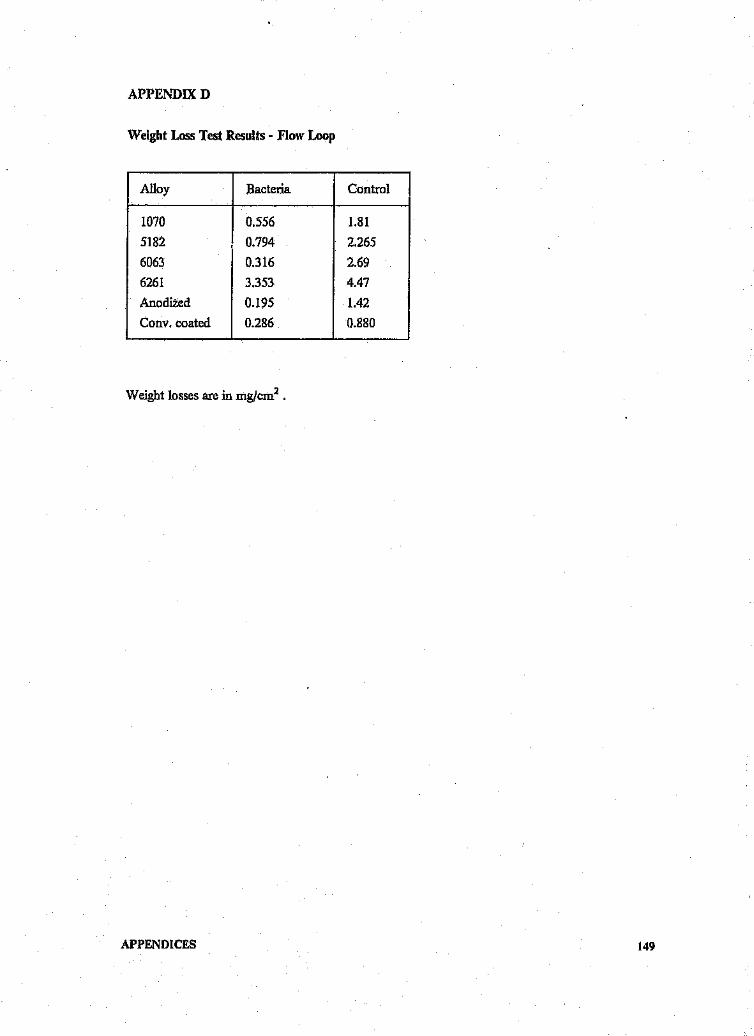
APPENDIXD
Weight Loss Test Results - Flow Loop
Alloy Bacteria Control
1070 0.556 1.815182 0.794 2.2656063 0.316 2.696261 3.353 4.47Anodized 0.195 1.42Cony. coated 0.286 0.880
Weight losses are inmg/cm2•
APPENDICES 149

Author: Bondanno Angela.Name of thesis: Microbial corrosion of aluminium alloys in mine water.
PUBLISHER:University of the Witwatersrand, Johannesburg©2015
LEGALNOTICES:
Copyright Notice: All materials on the Un ive rs ity of th e Witwa te rs ra nd, J0 han nesb u rg Li b ra ry websiteare protected by South African copyright law and may not be distributed, transmitted, displayed or otherwise publishedin any format, without the prior written permission of the copyright owner.
Disclaimer and Terms of Use: Provided that you maintain all copyright and other notices contained therein, youmay download material (one machine readable copy and one print copy per page)for your personal and/oreducational non-commercial use only.
The University of the Witwatersrand, Johannesburg, is not responsible for any errors or omissions and excludes anyand all liability for any errors in or omissions from the information on the Library website.