Embed Size (px)
Citation preview

Bond Graph Modelling : a good communication toolbetween University and Industry
Daniel Jaume, Michel Vergé Michel Delhom, Patrick RoyerLaboratoire d'automatique des Arts et Métiers PSA/DRAS, route de Gisy
21 rue Pinel, France 78140 Velizy-VillacoublayFrance 75013 Paris tel : 33.1.41.36.25.58
tel : 33.1.42.16.88.44fax : 33.1.45.86.21.18
e-mail : [email protected]
Keywords : modelling, bond-graphs, mechatronics, automotive industry
AbstractThe aim of this paper is the interest of the
use of bond graphs as a modelling tool. The goal ofthis tool is to exchange knowledge between differentcommunities such University and Industry. The paperwill treat of how PSA had developed a data base toincorporate different models of parts of a car. Thesemodels are coming from their own researchdepartment and from partner university researchlaboratories. They allow a car maker to designquickly a new type of car.
1. IntroductionIn teaching sciences for engineers, we must
model physical phenomena and physical systems. Thenecessary steps are writing equations for eachelementary physical system, sorting these equationsand implement them in a solver. This approachrequires attention when the system to model iscomplex and multidisciplinary (mechanical, hydraulic,thermal).
In the car industry, Mechatronics, acombination of Mechanics and Electronics had leadedto replace functions previously achieved by mechanicaldevices (Electronics injection had replacedmechanically driven spark emission) and to introduce"not previously thought of" functions such AntiBlocking System or traction control.
The highly competitive car market pushes thecompanies into a shortening of the product life cycle.Modelling, analysis and simulation are the necessarytools to reach this goal
A common tool enabling a unified approachto the physical modelling of various disciplines is theBond graph [1],[2],[3]. The hypothesis of localisedphysical elements enables a graphical representationsupported by a complete coherent algebra.
The heavy use of mathematical modellingtechniques in conjunction with user computerimplementation will make fast iterations possible atthe simulation level and the "Do it right at first"achievement. Mechatronics enhances these factorsbecause its necessary multidisciplinary interfaces canonly be resolved in that way [8].
The French car maker PSA Peugeot Citroënhad planed to develop the modelling of each part of acar using bond graphs [4],[6],[7]. In the frame of anEuropean project OLMECO (an Open Library formodels of Mechatronics Components), had engagedresearches to create a library for mechatronicscomponent models. So, engineers have the use ofavailability of validated reusable models. Bong graphshave been chosen as universal modelling language.
2. Modelling with Bond GraphsThe example concern an industrial problem :
the design of a car brake system. In this paper, themodel is chosen very simple (fig 1). The half car ismoving on the plane. The body frame is attached atthe centre of mass G. The main directions are : Gxoriented toward the front, Gz oriented toward the top.A classical suspension link the body to the wheels.
x
z
G ( front )
( top )
Figure 1. Mechanical system
The torque applied on the wheels are obtainedfrom the brake pedal using an hydraulic transmission(Fig 2).
Brake pedal
load sensing brake
frontrear
Figure 2. Hydraulic circuit

A 150 bars source pressure is provided by a pump andthe brake pedal modulate this pressure which is sent tothe front wheel. A load sensing brake attenuate thispressure versus the load to the rear wheel. The oilpressure reach a single piston sliding floating callipersthrough a flexible pipe for the front wheel and a spiralservice brake line for the rear wheel.Three dynamic must be taken into account- the hydraulic dynamic very fast,- the wheel dynamic, medium,- the body dynamic, slow.
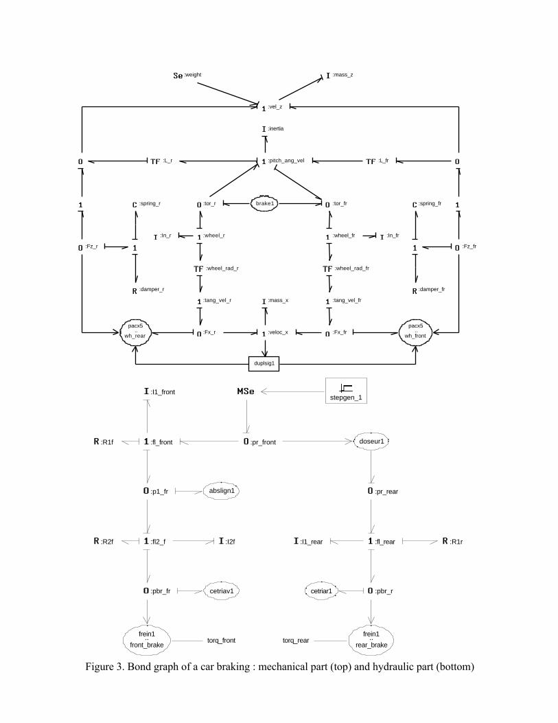
The figure 3 presents the bond graph of a brakingprocess of automotive vehicle with mechanic (top) andhydraulic (bottom) part.Many observations may be done about the hydraulicpart.The zero junctions are used to represent pressures andone junctions for flows. A rigid service brake linemust be modelled with a resistive (R) and inertia (I)
elements with : 4dL128
Rπ
νρ=SL
Iρ=
ρ mass density,ν cinematic viscosity,L length of pipe,S cross section,d diameter.A flexible pipe (front wheel) is modelled like a rigidone added by a special C element to take into accountthe compliance of the pipe. It means that the flexiblepipe absorb a volume of oil depending the pressure.The special function "abslign1" shows this element.The special function "cetrierav" represents themechanical compliance of the calliper under the forceapplied on the brake disc. These elements allow thesimulation to take into account several phenomenaclose of the reality. The special element "frein1"provides the transformation between brake pressureapplied on the piston and the braking torque appliedon the wheel.Concerning mechanical part of the bond graph, manyobservations may be done. The zero junctions are usedto represent forces and one junctions for velocities.The mains velocities are :vel_z vertical velocity of G,vel_x horizontal velocity of G,pitch_ang_vel angular velocity of G,wheel_frangular velocity of the
front wheel,tang-vel_fr tangential velocity of the
front wheel tyre.Fx_fr is the horizontal force applied by the front tyre tothe car.The vehicle is decelerated through a friction forceexisting between wheel and road. The tyre-roadinterface is modelled with Pacejka model [9]. Abraking torque provides a wheel slip expressed by :
xvel
veltangxvelWs
___ −
=
The slip determines the friction coefficient µ through afunctional dependence shown in figure 4. The curve isstrongly dependent on road surface conditions.
Dry pavement
Wet asphalt
Snow
0 1Ws
µ
Figure 4
The force Fx_fr value is expressed by :Fx_fr=µ.Fn Fn beeing the normal force applied on thetyre. It is interesting to note that the tyre-road interfaceis determined by a non physical law. It is computed inpacx5 (fig3).The figures 5 and 6 show the results of a simulationusing previous model. The car (a XM Citroën model)is launched with 20 m/s velocity and braked with a120 bar pressure on the front wheel on a wet road. Atthe figure 5, the front wheel hydraulic phenomena arepresented. The A curve is the pressure generated bythe brake pedal. The B curve is the pressure applied tothe calliper piston, one can see a delay due to themotion of the friction pad until it reaches the brakedisc. The C curve is the oil flow toward the calliperpiston, the oscillations are due to the flexible pipedynamic.The hydraulic variable behaviour has been verified byexperiments.On figure 6 are shown mechanical variablesrepresenting the car behaviour under braking operation.The time scale is zero to 5 seconds, the brake actionbegins at t= 0.5 s. The A and B curves arerespectively the car and tyre velocities, one can see thewheel slip increasing and decreasing providing brakingforce. The C curve is the normal force applied on thefront wheel. This force is increasing due to the brakingtorque effect improving the braking force ; There is anopposite effect on the rear wheel. The car is stopped in3.4 seconds.
3. Integration into a libraryThis study may allow the design of a car
braking system for a new model. In order to reach thisgoal, it is necessary to use a specific organisation :library of components, vehicle parameters formechanical and hydraulic parts… This study must bereorganised to be added in a model data base to beeasily reusable for an engineer.
In order to describe the model's data base it isnecessary to define user needs. Basically the mainobjective is the creation of a library of mechatronicscomponents in view of their reusing.A model state evolves during its life :- generic model,- instantiated model,

- simulation model,- validated model.
A generic model is a general representation of an actualmechatronics system. It describes physical phenomenataken into account to represent an organ. It owns localand external components. A generic model isassociated to physical organ as electrical motor,battery… The figure 7 shows a technologic view of ageneric model of an electric car, the figure 8 shows amathematical representation of this generic modelusing a bond graph. The figures 9 shows the sub-models used by the generic model. The figure 10shows the different kind of electrical motors availablein the library.
An instantiated model is used to describe thebehaviour of a particular organ already described by ageneric model. For example, from an electricalmachine generic model you may built a electrical tomechanical transformer (motor) or its invert (electricalgenerator) Two kinds of instantiated model arepossible. An instantiated model needs a genericmodel, a causal analysis and a set of structuralparameters.
A Simulation model allows dynamicalanalysis of an instantiated model. It needs a set ofinitial conditions, the definition of external entries anda numerical integration method with a computationstep.
4. ConclusionThe study presented is a characteristic
example of a university research work. It is importantto note that bond graphs have been chosen as dynamicsystem powerful tool modelling using the sameformalism for hydraulic and mechanical parts.
At the level of a car maker researchdepartment, it is important to develop fruitfulcollaboration with university research laboratories.Nevertheless, each study must be standardised to be
used immediately, to be stored in a data-base and tobe reused in other context.
References:
[1] D. Karnopp, D. Margolis, R. Rosenberg -"Systems dynamics : A unified approach" JohnWiley, 1990.
[2] J. Thoma - "Simulation by Bond graphs"Springer-Verlag, 1990.
[3] A. Bos - "Modelling multibody systems interms of multibond graphs with application toa motorcycle" Ph. D. thesis University ofTwente, Netherlands 1986.
[4] W. Drozdz - "Development and validation of abond graph handling model of an automobile"Journal of the Franklin Institute Vol 5/6 pp941-957, 1991.
[5] E. Fahrentholde J. Wargo - "Vector bondgraph analysis of mechanical systems" Journalof dynamics and control, Vol 113 pp 344-352Sept 1991.
[6] D Jaume, J. Chantot -. "A Bond-GraphApproach to the modelling of thermicsproblems under the hood" Proceedings of theIEEE SMC'93 Conference Le Touquet, Vol 2pp 228-233, Oct 93.
[7] D. Jaume, M. Vergé - "3D Dynamic carmodelling using bond graphs" Proceedings ofthe conference IEEE-SMC CESA'96, Vol 1 pp161-166, July 96 Lille.
[8] M. Kajitani - "A concept of mechatronics"Journal of Robotics and mechatronics Vol 1, n°1, June 1989.
[9] H.B. Pacejka, E. Bakker, L. Nyborg - "Tyremodelling for use in vehicle dynamics studies"SAE Paper N° 870421,1987.
:veloc_x
:tang_vel_fr:tang_vel_r
:wheel_fr:wheel_r
:pitch_ang_vel
:vel_z
:Fx_fr:Fx_r
:tor_fr:tor_r
:Fz_fr:Fz_r
:wheel_rad_fr:wheel_rad_r
:L_fr:L_r
:weight
:mass_x
:In_fr:In_r
:inertia
:mass_z
:spring_fr:spring_r
:damper_fr:damper_r
pacx5
wh_front..
pacx5
wh_rear..
duplsig1
brake1
:pbr_r:pbr_fr
:p1_fr :pr_rear
:pr_front
:fl_rear:fl2_f
:fl_front doseur1
frein1
rear_brake..frein1
front_brake..
stepgen_1
abslign1
:R1r:R2f
:R1f
:I1_rear:I2f
:I1_front
cetriav1 cetriar1
torq_reartorq_front
Figure 3. Bond graph of a car braking : mechanical part (top) and hydraulic part (bottom)

0 time 0.3
A
A
A
1.4e+07
0
brake_1_1`pr_front`o
B
B
B
1.4e+07
0
brake_1_1`pbr_fr`out
C
C
C
5e-05
0
brake_1_1`fl2_f`outp
car1 - exp2
C
CB
BA A
Figure 5. Hydraulic behaviour of front wheel
0 time 5
A
A
A
22.5
-2.5
veloc_x`outp
B
B
B
22.5
-2.5
tang_vel_fr`outp
C
C
C
5000
3500
Fz_fr`outp
D
D
D
0.04
-0.04
pitch_angle`state
car1 - exp4
D
D
C C
B
B
A
A
Figure 6. Mechanical behaviour of front wheel

Figure 7. Technologic view of electrical car generic model.
Figure 8. Mathematical view of electrical car generic model.

Figure 9. Library part of electrical car generic model.
Figure 10. Library kind of electrical motor