Embed Size (px)
Citation preview

Boiling Water Reactor GE BWRA4 Technology
Technology Manual
Chapter 2.4
Recirculation System

G.E. Technology Systems Manual Recirculation System
Table Of Contents
2.4 RECIRCULATION SYSTEM ........................................................................... 1
2.4.1 Introduction ......................................................................................... 1
2.4.2 System Description ............................................................................... 1
2.4.3 Component Description ........................................................................... 1
2.4.3.1 Recirculation Loop Suction Piping ................................................... 2
2.4.3.2 Recirculation Pumps .................................................................... 2
2.4.3.3 Recirculation Pump Discharge Piping ............................................... 3
2.4.3.4 Jet Pumps ................................................................................. 3
2.4.3.5 Reactor Water Sampling Line ......................................................... 4
2.4.4 System Features .................................................................................. 4
2.4.4.1 System Operation ........................................................................ 4
2.4.4.2 Jet Pump Vibration ...................................................................... 4
2.4.4.3 Recirculation Pump Seal Operation .................................................... 5
2.4.5 System Interfaces ................................................................................. 5
2.4.6 Summary ......................................................................................... 6
List Of Figures
2.4-1 Recirculation System .................................................................................. 7
2.4-2 Recirculation Loop Instrumentation ................................................................ 9
2.4-3 Jet Pump Assembly ................................................................................... 11
2.4-4 Jet Pump Principle .................................................................................... 13
2.4-5 Recirculation Pump Seal Assembly .............................................................. 15
" "I. n P7l
USNRC Technical Training Center 2.4-i Rev •7
G.E. Technolo.v Sstems Manuale
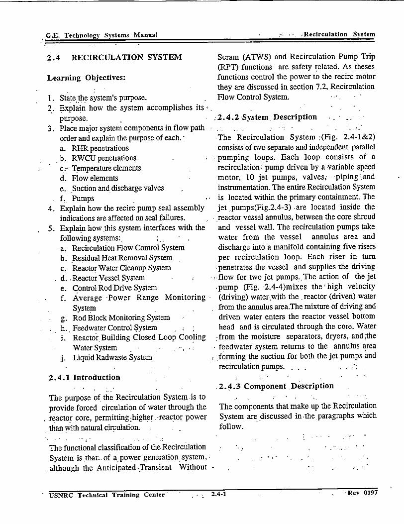
2.4 RECIRCULATION SYSTEM
Learning Objectives:
1. State the system's purpose. 2. Explain how the system accomplishes
purpose. 3. Place major system components in flow
order and explain the purpose of each." a. RHR penetrations b. RWCU penetrations c.,- Temperature elements d. Flow elements e. Suction and discharge valves f. Pumps
4. Explain how the recirc pump seal asser indications are affected on seal failures.
5. Explain how this system interfaces with following systems:, a. Recirculation Flow Control Systemb. Residual Heat Removal System, c. Reactor Water Cleanup System d. Reactor Vessel System e. Control Rod Drive System f. Average -Power Range Mo:
System g. Rod Block Monitoring System h. Feedwater Control System i. Reactor Building Closed Loop
Water System j. Liquid Radwaste System
nito
Coc
2.4.1 Introduction
The purpose of the Recirculation System is to provide forced circulation of water through the reactor core, permitting-higher - reactor power than with natural circulation.
s its,,
path
Scram (ATWS) and Recirculation Pump Trip (RPT) functions are safety related. As theses functions control the power to the recirc motor they are discussed in section 7.2, Recirculation Flow Control System.
2.4.2 -System, Description
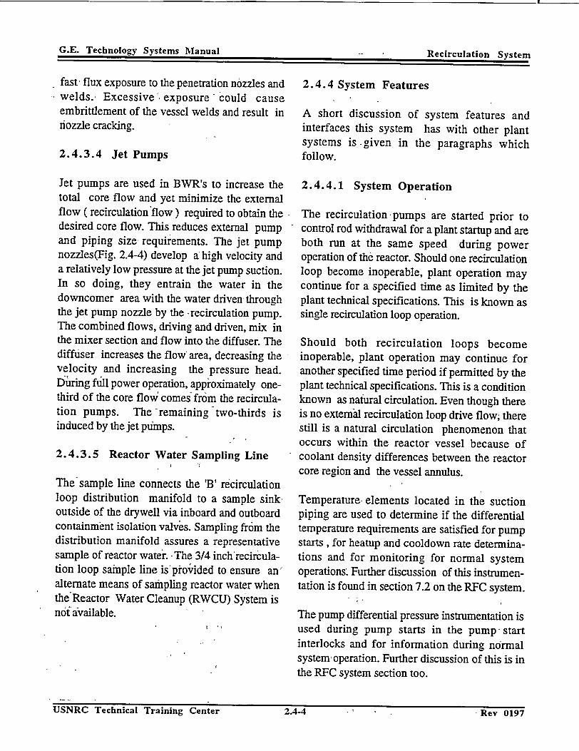
-The Recirculation System-(Fig. 2.4-1&2) consists of two separate and independent parallel
pumping loops. Each loop consists of a recirculation, pump driven by a variable speed motor, 10 jet pumps, valves, piping-and instrumentation. The entire Recirculation System is located within the primary containment. The
ably jet pumps(Fig.2.4-3) are located inside the reactor vessel annulus, between the core shroud
1 the and vessel wall. The recirculation pumps take water from the vessel annulus area and discharge into a manifold containing five risers per recirculation loop. Each riser in turn
-penetrates the vessel and supplies the driving -,.flow for two jet pumps.The action of the jet
,pump (Fig. -2.4-4)mixes the, high velocity ring - (driving) water~with the , reactor (driven) water
from the annulus area.The mixture of driving and driven water enters the reactor vessel bottom head and is circulated through the core. Water
)ling :from the moisture separators, dryers, and ;the - feedwater system returns to the annulus area *forming the suction for both the jet pumps and recirculation pumps. .
,2.4.3 Component. Description
The components that make up the Recirculation System are discussed in, the paragraphs which follow.
The functional classification of the Recirculation
System is that-- of a power generation system,, .
although the Anticipated -Transient Without .
USNRC Technical Training Center 2.4-1 zev ui)�i1 • 2.4-1
- .... ,Recirculation System
-imev 01.97USNRC Technical Training Center

G.E. Tichnology Systems Manual
2.4.3.1 Recirculation Loop Suction Piping
The two recirculation loops remove water from the reactor vessel downcomer annulus area approximately 180' apart. Each 28 inch recirculation pump suction line,' conta'ins pump differential pressure instruments,temperature elements, a single 28 inch suction isolation valve and a penetration to the RWCU system. The 'B' recirculation suction line contains an additional penetration for the Residual Heat Removal (RHR) System.
The RHR System penetration in 'B' loop is a 20 inch'line that provides a 'suction for the shutdown cooling mode of the RHR System (Section 10.4).
Suction Isolation Valve
The Recirculation System. suction isolation valves are motor operated 28 inch gate valves used to isolate the recircilation-K pumps for maintenance. Each, valve is ifhdividually controlled from the control room by a hand switch.
Because the removal of the reactor recirculation gate valve internals would require unloading the core, the valves are provided with'high quality backseats that permit replacement of stem packing while the system is full of water. One objective of the valve design is to minimize the need for maintenance of the valve internals.
2.4.3.2 Recirculation Pumps
A variable speed, single stage, vertically mounted centrifugal pump is provided in each recirculation loop with the suction and discharge lines welded to the pump casings. The pumps are
located below the reactor vessel to satisfy NPSH requirements. At less than 20% feedwater flow or if reactor water level is below level 3, the pump speed is interlocked to minimum to assure adequate NPSH. The recirculation pump is driven by a variable speed motor, which can operate from 11.5 Hz to 57.5 Hz (via the Recirculation Flow Control System, Section 7.2).
The recirc pump motor windings and bearing oil are cooled by the RBCLCW system. The motor has a vibration sensor which alarms in the control room on high vibration. The oil level in the motor bearings is monitored for level and alarms in the control room on low level.
Each recirculation pump is equipped with a dual mechanical shaft seal assembly (Figure 2.4-5). Each assembly consists of two seals built into a cartridge that can be replaced without removing the motor from the pump. Each individual seal in the cartridge is designed for full pump design pressure, so that one seal can adequately limit leakage in the event that the other seal should fail. The pump shaft passes through a breakdown bushing in the pump casing to reduce leakage to approximately 60 gpm in the event of gross failure of b•oth shaft seals. The cavity temperature and pressure of each seal are monitored to indicate seal performance and condition. The seals are cooled by the RBCLCW system. On loss of the cooling water pump operation is limited to preclude failure of the seals from overheating and/or motor damage.
During normal- operation, the two sets of seals share the sealing function of the assembly. This is possible because there is a pressure breakdown orifice internal to the seal cartridge. Each seal provides approximately 500 psid-across its surface. The second seal cavity receives a small
T17,%rT,, r..!.u'
Rev 01972.4-2
--- ~ ~~~ ~~~ -n yslll I ll It1 tem !
-_t r l. •€;11i1al Iraining t-enter
I - II Recirculation Systemy.r.,. I cUUoiUg.•U y
amount of flow through a pressurebreakdown orifice. This staging flow allows the second seal to provide some of the.pump sealing load. The
second stage seal cavity is drained through another orifice to the drywell -equipment drain sump.
The recirculation pumps, as well as piping and
valves, are supported by hangers to avoid the use',
of expansion loops that would .be required if the pumps were anchored. The only location where
the piping is rigidly fixed is at the connection to the reactor vessel.'At other places, the piping is
-. free to expand and contract within the limits of
, snubbers and hangers.
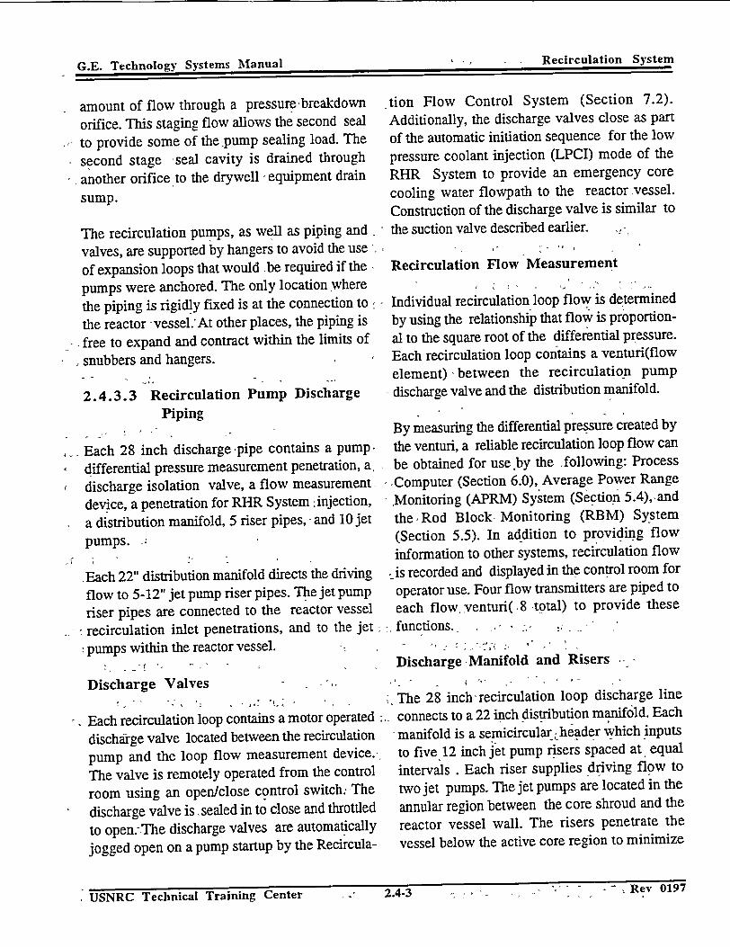
2.4.3.3 Recirculation Pump Discharge Piping
* Each 28 inch discharge pipe contains a pumpdifferential pressure measurement penetration, a.
discharge isolation valve, a flow measurement device, a penetration for RHR System Jinjection, a distribution manifold, 5 riser pipes, -and 10 jet pumps.
.Each 22" distribution manifold directs the driving flow to 5-12" jet pump riser pipes. The jet pump riser pipes are connected to the reactor vessel
-recirculation inlet penetrations, and to the jet pumps within the reactor vessel.
Discharge Valves
- Each recirculation loop contains a motor operated
discharge valve located between the recirculation pump and the loop flow measurement device.
The valve is remotely operated from the control
room using an open/close control switch: The
discharge valve is, sealed in to close and throttled to open.-,The discharge valves are automatically jogged open on a pump startup by the Recircula-
tion Flow Control System (Section 7.2). Additionally, the discharge valves close as part of the automatic initiation sequence for the low
pressure coolant injection (LPCI) mode of the
RHR System to provide an emergency core
cooling water flowpath to the reactor vessel. Construction of the discharge valve is similar to the suction valve described earlier.
Recirculation Flow Measurement
SIndividual recirculation loop flow is determined by using the relationship that flow is proportional to the square root of the differential pressure. Each recirculation loop contains a venturi(flow element) between the recirculation pump discharge valve and the distribution manifold.
By measuring the differential pressure created by
the venturi, a reliable recirculation loop flow can be obtained for use ,by the following: Process
-Computer (Section 6.0), Average Power Range Monitoring (APRM) System (Section 5.4), and
the, Rod Block- Monitoring (RBM) System (Section 5.5). In addition to providing flow
information to other systems, recirculation flow - is recorded and displayed in the control room for
operator use. Four flow transmitters are piped to each flow, venturi( .8 -total) to provide these functions.
Discharge -Manifold and Risers
The 28 inch, recirculation loop discharge line connects to a 22 inch distribution manifold. Each
manifold is a semicircular header which inputs to five 12 inch jet pump risers spaced at, equal
intervals . Each riser supplies driving flow to
two jet pumps. The jet pumps are located in the
annular region between the core shroud and the
reactor vessel wall. The risers penetrate the vessel below the active core region to minimize
. . .. ... •Rev 0197I USNRC Technical Training Center . • /,, .r4 °.•
G.E. Technology Systems Manual.Y. bAsa
fast, flux exposure to the penetration nozzles and welds.- Excessive' exposure could cause embrittlement of the vessel welds and result in nozzle cracking.
2.4.3.4 Jet Pumps
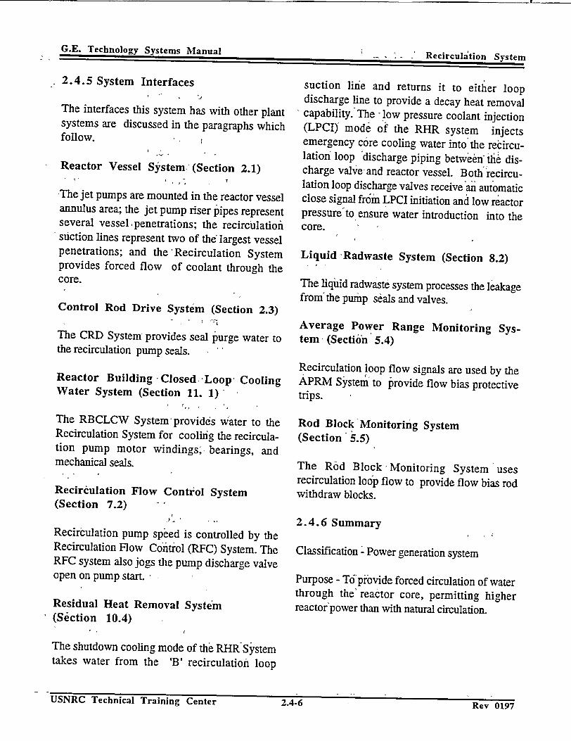
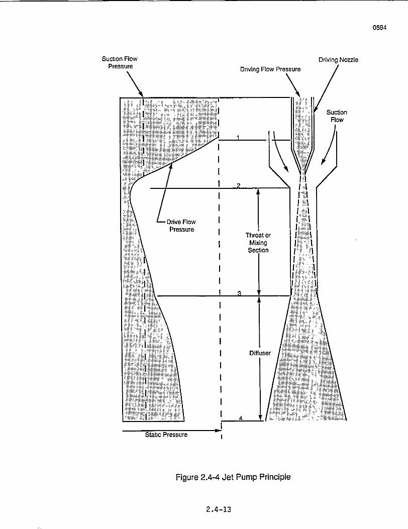
Jet pumps are used in BWR's to increase the total core flow and yet minimize the external flow ( recirculation flow ) required to obtain the desired core flow. This reduces external pump and piping size requirements. The jet pump nozzles(Fig. 2.4-4) develop a high velocity and a relatively low pressure at the jet pump suction. In so doing, they entrain the water in the downcomer area with the water driven through the jet pump nozzle by the -recirculation pump. The combined flows, driving and driven, mix in the mixer section and flow into the diffuser. The diffuser increases the flowi area, decreasing the velocity and increasing the pressure head. During full power operation, approximately onethird of the core flow comes from the recirculation pumps. The remaining two-thirds is induced by the jet pumps.
2.4.3.5 Reactor Water Sampling Line
The sample line connects the 'B' recirculation loop distribution manifold to a sample sink, outside of the dryweU via inboard and outboard containment isolation valves. Sampling from the distribution manifold assures a representative sample of reactor wate'r. -The 3/4 inch recirculation loop sample line is'ptoided to ensure anr alternate means of sampling reactor water when the'Reactor Water Cleanup (RWCU) System is not available.
2.4.4 System Features
A short discussion of system features and interfaces this system has with other plant systems is -given in the paragraphs which follow.
2.4.4.1 System Operation
The recirculation 'pumps are started prior to control rod withdrawal for a plant startup and are both run at the same speed during power operation of the reactor. Should one recirculation loop become inoperable, plant operation may continue for a specified time as limited by the plant technical specifications. This is known as single recirculation loop operation.
Should both recirculation loops become inoperable, plant operation may continue for another specified time period if permitted by the plant technical specifications. This is a condition known as natural circulation. Even though there is no external recirculation loop drive flow; there still is a natural circulation phenomenon that occurs within the reactor vessel because of coolant density differences between the reactor core region and the vessel annulus.
Temperature, elements located in the suction piping are used to determine if the differential temperature requirements are satisfied for pump starts , for heatup and cooldown rate determinations and for monitoring for normal system operations'. Further discussion of this instrumentation is found in section 7.2 on the RFC system.
The pump differential pressure instrumentation is used during pump starts in the pump start interlocks and for information during normal system, operation. Further discussion of this is in the RFC system section too.
*1CThTflt. 'r . . -. - - -iecnnicai iraining Leflier Rev 0197. Rev 0197
•aL •m•avxl b..lW J@ • L• J JA
uSN.RC• lechnncal training Center 2.4-4

G.E. Technology Systems Manual -Rcruain.yti
2.4.4.2 Jet Pump Vibration
When operating both recirculation pumps, a hig] flow difference between the two loops can causi flow reversal or oscillation of flows in the loi flow loop. This reversal or oscillation can resu] in vibration of the jet pumps and riser braces. Ti minimize, vibration and ,prevent fatigue proceduralcontrols are imposed..Recirc pum, speeds shall be within 5%-of each other whe core flow is equal to or greater than'70% of ratei and within 10% when less than 70%. Durin idle pump startup, with the other pump i operation, it's also necessary to reduce th operating pump's speed to less than 50% prior t starting a pump to reduce or minimize thes effects.
2,4'.4.3 Recirculation Pump Seal., , Operation
The recirculation pump seal assembly. (Figur 2.4-5) is kept clean and cool by a seal purg supply. The seal purge supply provides continuous flow of clean, cool water from th Control Rod Drive Hydraulic System (Sectio 2.3), to maintain a net flow of clean watc through the pump seals. A flow of approximate] 4 gpm-is- routed to each pump .through restricting orifice, flow regulator, -and flo' indicator.
Approximately .75 gallons per minute floxm through the seal cartridge as staging flow; whi. the remainder flows around the pump shaft an breakdown bushing into the impeller cavity. Th seal purge reduces the possibility of seal damag because of introduction of foreign material froi an unclean piping system, and also reduces t1 seal temperature by its cooling effect.
The seal purge increases seal life while reducing radioactive discharge to the Liquid Radwaste
hi System.
V Alarms are provided on the staging flow lines It and seal leakoff lines to provide indication of
seal failure. These alarms, together, with the •, pressure indicators, allow the operator to
p analyze system failure. A flow switch in the seal n staging line - provides a high flow alarm at .9 dl gpm and a low flow alarm at -.5 ogpm.' A second g flow switch located -on the second seal leakoff n flow line (normally zero flow) alarms high at .25 e :gpm., 0
e Failure of the inner (number 1) seal is indicated -,by a number 2 seal pressure increase to higher than normal and an increase in staging flow through the second orifice which-causes a high flow alarm .
e 'Failure of the outer (number 2) seal is indicated e by number 2 . seal -pressure indication -being a lower than normal (depending on the extent of
ýel - the failure), and the outer seal flow switch'which n. - detects leakage and alarms high along with the ,r low flow alarm on the staging flow. ,
a Failure of both seals is indicated by leakage past w the outer seal -resulting in a high flow alarm
(leakage would be limited to •approximately 60 gpm by the breakdown bushing) and a pressure
s,:. decrease in both seals which is dependent on the le -magnitude of the failure. id , is The recirculation pump seal cavity requires e, forced cooling due to the heat of the reactor n water and the friction-generated in the .sealing le surfaces. Cooling water, provided by the Reactor
Building Closed Loop Cooling Water (RBCLCW) System, flows through-a cooling jacket around the seal assembly.
USNRC Technical Training Center - - 2.4-5 �ev ux�ISUSNRC Technical Training Center
S.... .. Recirculation .System
KeV U1.- , 2.4-5
G.E. Technology Systems Manual
2.4.5 System Interfaces
The interfaces this system has with other plant systems are discussed in the paragraphs which follow.
Reactor Vessel System '(Section 2.1)
-The jet pumps are mounted in the reactor vessel annulus area; the jet pump riser pipes represent several vessel, penetrations; the recirculatiofi suction lines represent two of the largest vessel penetrations; and the 'Recirculation System provides forced flow of coolant through the core.
Control Rod Drive System (Section 2.3)
The CRD System provides seal purge water to the recirculation pump seals.
Reactor Building -Closed-- Loop Cooling Water System (Section 11. 1)
The RBCLCW System provides water to the Recirculation System for cooling the recirculation pump motor windings, bearings, and mechanical seals.
Recirculation Flow Control System (Section 7.2)
Recirculation pump speed is controlled by the Recirculation Flow Contiol (RFC) System. The RFC system also jogs the pump discharge valve open on pump start.
Residual Heat Removal System (Section 10.4)
The shutdown cooling mode of the RHR System takes water from the 'B' recirculation loop
Recirculation System
suction linie and returns it to either loop discharge line to provide a decay heat removal capability. The -low pressure coolant injection (LPCI) mode of the RHR system injects emergency core cooling water into the recirculation- loop 'discharge piping between the discharge valve-and reactor vessel. Both recirculation loop discharge valves receive an automatic close signal fr6im LPCI initiation and low reactor pressure to ensure water introduction into the core.
Liquid -Radwaste System (Section 8.2)
The liquid radwaste system processes the leakage from the pump seals and valves.
Average Power Range Monitoring System (Section 5.4)
Recirculation loop flow signals are used by the APRM System to provide flow bias protective trips.
Rod Block Monitoring System (Section 5.5)
The Rod Block, Monitoring System uses recirculation loop flow to provide flow bias rod withdraw blocks.
2.4.6 Summary
Classification - Power generation system
Purpose - T6"piovide forced circulation of water through the reactor core, permitting higher reactorpower than with natural circulation.
IJSNRC Tec-16n.-.I T;.;.i. fRev 0197
L_
aa b l . as I11111 en. terI~• Z.14-0

GE~ Technology Systems Manual RcruainSse
Components - Suction pipes; suction valves;
pumps; discharge valves; flow venturi; distribution manifold; jetpump riser pipes; jetpumps; and various penetrations.
System Interfaces - Reactor Vessel System; Control Rod Drive System; Recirculation Flow Control System; Reactor Building Closed Cooling Water System; Residual Heat Removal System; Liquid Radwaste System; Average Power Range Monitoring System; Rod Block Monitoring System.
Rsx II.L7
USNRC Technical Training Center
Recirculation System
Rev UIU2.4-7
JET PUMP
RISER OUTLET
MANIFOLD
PUMP DISCHARGE"
LINE
BYPASS VALVE
Discharge Valve
Pumps
PUMP DISCHARGE VALVE
Figure 2.4-1 Recirculation System
Manifold / From
Discharge Valve
.0 CJ1

0594
Primary Containment
From Reactor Vessel Annulus Region
H>
From Motor Beanng & Seal - - -
Cavity Cooling Water
-RHR
-4
t
To DWEDS
APRM & RBM "Flow Biasing
L ... To Tmp Recarder
-. - Comute "Input
To RHR Shutdown Cooling ( Loop *B" only) STo RWCU System
Figure 2.4-2 Recirculation Loop Instrumentation
2.4-9

HOLD-DOWNS
INLET (I OF 2)
MIXER (1 OF 2)
SHROUD
WEDGE AND RESTRAINER (I OF 2)
CORE SUPPORT
INSTRUMENTATION LINE
DIFFUSER (I OF 2) -
REACTOR PRESSURE VESSEL
* RPV RECIRCU LATION INLET NOZZLE (I TO EACH JET PUMP RISER)
Figure 2.4-3 Jet Pump Assembly
2.4-11
Driving Nozzle
Static Pressure!
Figure 2.4-4 Jet Pump Principle
2.4-13
Suction Flow Pressure
0594

H0.9 gpm
H
0.25 gpm
DWEDS (CONTROLLED LEAKAGE
AT 0.75 gpm)
CONTROLLED / PRESSURE
- _
BREAK DOWN (INTERNAL AT SEAL)
FAILURE OF NO. 1 SEAL ONLY:
FAILURE OF NO. 2 SEAL ONLY:
FAILURE OF BOTH SEALS:
PLUGGING OF NO. 1 INTERNAL "RO0:
PLUGGING OF NO. 2 INTERNAL "RO":
SECOND SEAL (NO. 2)
FIRST SEAL (NO. 1)
T DWEDS
SEAL PURGE FROM CRD SYSTEM
BREAKDOWN BUSHING
NO. 2 SEAL PRESSURE WOULD APPROACH NO. 1 SEAL PRESSURE.
LEAKAGE THRU NO. 2 ORIFICE WILL GO TO -1.1 gpm AND FS "A" WILL ALARM HI
AT 50-9 gpm.
NO. 2 SEAL PRESSURE WOULD DROP DEPENDENT UPON MAGNITUDE OF FAILURE.
LEAKAGE THRU FS '1B" WOULD EXCEED 0.25 gpm AND ALARM HI.
TOTAL LEAKAGE OUT OF THE SEAL ASSEMBLY WOULD APPROACH 60 gpm AS
LIMITED BY THE BREAKDOWN BUSHING. BOTH FS "A- AND FS "'WOULD
ALARM HIGH. PRESSURE IN BOTH SEALS WOULD DROP DEPENDING UPON
MAGNITUDE OF FAILURE. (NO. 1 PRESSURE MIGHT NOT DROP SIGNIFICANTLY
UNLESS FAILURE WAS LARGE.)
NO. 2 PRESSURE WOULD GO TOWARD ZERO AND FLOW THRU FS "A" WOULD
APPROACH ZERO AND ALARM LOW AT 0.5 gpm
NO. 2 SEAL PRESSURE WOULD APPROACH NO. 1 SEAL PRESSURE. CONTROLLED
LEAKAGE WOULD APPROACH ZERO AND ALARM LOW AT 0.5 gpm.
Figure 2.4-5 Recirculation Pump Seal Assembly
2.4-15

Boiling Water Reactor GE BWR/4 Technology
Technology Manual
Chapter 2.5
Main Steam System

G.E. Technology Systems Manual Main Steam System
Table of Contents 2.5 MAIN STEAM SYSTEM .......................................... I
2.5.2 Component Description ...................................... 2
2.5.2.1 M ain Steam Lines .................. .............. I.......................... 2
2.5.2.2 Reactor Head Vent .................. ...................... 2
2.5.2.3 Safety/Relief Valves ................................... 2
2.5.2.4. Flow Restrictors ...................................... 3
2.5.2.5 Main Steam Isolation Valves (MSIV's) .................. 4 2.5.2.6 Steam LineDrains ............. ........................ 5
2.5.2.8 Turbine Stop Valves ...................................................... 6
2.5.2.10 Turbine ...................................... .................. 6
2.5.2.11 Moisture Separator/ Reheaters .............................
2.5.2.12 Combined Intermediate Valves ............................. 7
2.5.2.13 Other Steam Equipment ................................. 8
2.5.3 System Features and Interfaces .. . ..... ..... 8
2.5.3.1 Normal Operation .............................................................. 9
2.5.3.2 Safety/Relief Valve Operation ............................................... 9
2.5.3.3 System Interfaces ............................................................ 10
2.5.3.4 PRA Insights .................................................................. 11
2.5.4 Sum m ary ..................................................................................... 11
List of Tables 2.5-1 Safety / Relief Valve Settings ............................................................ 13
USNRC Technical Training Center I 2.5-i Rev. 0197

I -__________
G.E. Technology Systems Manual Main Steam System
List of Figures 2.5-1 Main Steam System .................................................................... 15 2.5-2 Main Steam System (Cont.) ................................................. 17 2.5-3 Auxiliary Steam Headers ................................................................ 19 2.5-4 Steam Line Drains ........................................... 21 2.5-5 Safety / Relief Valve (Closed) ............................................................ 23 2.5-6 Safety / Relief Valve (Open) .............................................................. 25 2.5-7 Main Steam Isolation Valve ................................................................. 27 2.5-8 Main Steam Isolation Valve (Open) ..................................................... 29 2.5-9 Main Steam Isolation Valve (Closed) .................................................... 31 2.5-10 Safety/Relief Valve Arrangement ........................................................... 33 2.5-11 Moisture Seperator Reheater ............................................................... 35 2.5-12 Steam Seal Supply ......................................................................... 37 2.5-13 Main Turbine Sealing Steam ................................................................. 39 2.5-14 Turbine Glands ............................................................................ 41 2.5-15 Feed Pump Turbine Steam Seal ......................................................... 43
U�LNKU lechnical [raining Center 2.5-il Rev 0197USLNRC; Technical Training Center 2.5-ii1 Rev 0197

G.E. Technology Systems Manual Main Steam System
2.5. MAIN STEAM-SYSTEM
Learning Objectives
1. State the system's purpose(s). 2. Place the following system components in
flow path order and explain the purpose of each :
-a. Safety/Relief Valves b. Main Steam Line Flow Restrictors c. Main Steam Line Isolation Valves d. Equalizing Header e. Turbine Bypass Valves f. • Main Turbine g. Extraction Steam System , h. Moisture Separator Reheaters
3. Explain the different modes of safety/relief valve operation.
4. List the signals that will automatically close the main steam isolation valves and explain the reason for each.
5.- Explain how this system interfaces with the following systems or components:
a. Reactor Vessel System b. Reactor Core Isolation Cooling System
Sc. Offgas System d. Electro-hydraulic System e. Nuclear Steam Supply System f. Residual Heat Removal System g. Automatic Depressurization System h.. Condensate and Feedwater System i. Reactor Protection System j. Feedwater Control System
2.5.1 Introduction
The purposes of the Main Steam System are to direct steam from the reactor vessel to, the main turbine and other steam loads; to provide overpressure protection for the reactor coolant
system, and to direct steam to certain safety -systems.
The functional classification of the Main Steam System is that of a power generation system.
<[he Main Steam System does, however, contain three components which are engineered safety features (ESF). These ESF's are the main steam isolation valves, the main steam line 'flow restrictors, and the safety/relief valves.
The Main Steam (MS) System, shown in Figures 2.5-1, 2.5-2 and-.2.5-3, consists of four steam lines that originate at the reactor- vessel, penetrate the drywell (primary containmefit) ýtraverse the reactor building in a shielded steam tunnel and terminate in a pressure equalizing header in the turbine building. From the pressure equalizing header, steam is directed to the turbine stop
-valves,, bypass valves, reactor feed pump ,turbines, steam jet air ejectors, and turbine
gland seal steam. *
Within the containment each steam line contains a number of safety/relief valves for nuclear system
:overpressure protection, a steam flow restrictor to -limit the loss of inventory in the event of a
r'steam line rupture, and an inboard main steam isolation valve. The "A"s steam line contains three
-penetrations to provide continuous venting of the - reactor vessel head area during reactor'operation,
a reliable -steam -source to the Reactor , Core Isolation Cooling (RCIC) System, and to supply steam to the High Pressure Coolant Injection (HPCI) System.
Low point drains upstream of the inboard main steam isolation valves (MSIV's) penetrate each
Smain steam line and connect to a common drain header. The steam line drain header enters the reactor building yia a motor operated isolation valve and a guard pipe. Within the reactor
USNRC Technical Training Center 2.5-1 Rev 0197Rev •0197
G.E. Technology Systems Manual Main Steam System
USNRC Technical Training Center 2.5-1

G.E. Technology Systems Manual Main Steam System
building, each main steam line contains a redundant outboard MSIV and a low point drain connection. Passage through the reactor building is within a steam tunnel. This tunnel provides radiation shielding and a foundation for seismic supports. The low point drain' connections terminate at a common pipe which is attached to the main steam lines upstream of the inboard MSIV's and the main condenser.
From the reactor building, the four steam lines progress to the turbine building where' they are finally connected to a common pressure equalizing header. The pressure equalizing header provides a common point to route steam for plant usage.
2.5.2 Component Description
The components which makeup the Main Steam System are discussed in the paragraphs which follow.
2.5.2.1 Main Steam Lines
The main steam lines, shown in Figures 2.5-1 and 2.5-2, are each twenty-four inches in diameter and constructed of carbon. steel: The lines are welded to the reactor vessel shell area and have a design pressure and temperature, of 1250 psig and 5750 F, respectively. The system design and arrangement incorporates seismic considerations and provisions to'-mitigate the consequences of postulated pipe failures.
The use of four steam lines, to control a flow of
"10.5 x 10⁶ lb/hr, allows operational testing of the
MSIV's and permits high- power operation with one steam line isolated. Reduced individual pipe diameters provide a limitation on th6 differential pressure across reactor vessel internals during a single -steam line break. The steam dryer
differential pressure is of particular concern because failure of the dryer could result in interference with MSIV closure and thus prevent isolation, if the break occurred downstream of the MSIV's.
2.5.2.2 Reactor Head Vent
As shown in Figure 2.5-1, a vent connection is provided on the top head of the reactor vessel. The vent line serves to vent noncondensible gases from the upper vessel area during startup, normal operation, and vessel floodup. During operation at temperatures less than boiling, the noncondensibleý gases are vented to the drywell equipment drain stimp. At temperatures above boiling, the vent is directed to the "A" main steam line.
2.5.2.3 Safety/Relief Valves
The: purpose of the safety/relief valves (SRV's), Figures 2.5-5- and 2.5-6, is to prevent over pressurization of the nuclear process barrier from any abnormal operational transient. In addition to providing overpressure protection, seven (7) of the SRV's are also used by the Automatic Depressurization System (ADS, Section 10.2) to rapidly decrease reactor pressure during specific small break losý of coolant accidents. -There are a total of eleven (11) safety/relief valves, each with an approximate capacity of 815,000 lb/hr at 1100 psig.
The SRVs have three modes of operation: the safety mode, the relief (remote manual) mode, and the ADS mode.
The SRV's are located on each main steam line between the reactor :vessel and the steam line flow restrictors. The SRV's are mounted on a horizontal run of the steam piping to facilitate the
USNRC Technical Training Center 2.5-2 Rev 0197
K_
G.E. Technology Systems Manual Main Steam System
USNRC Technical Training Center 2.5-2 Rev 0197

G.E. Technology Systems ManualManSem ysm
SRV discharge piping configuration from the valve to the ,suppression pool and to avoid the necessity for removing sections of the discharge pipe when the vessel,,head is removed for refueling. The SPV's location also enhances their accessibility for maintenance.
Two vacuum breakers on each SRV discharge line serve to admit drywell atmosphere to the SRV discharge line in order to minimize the reduction in line pressure to below atmospheric pressure as steam in the line condenses following closure of the SRV. The vacuum breakers thus minimize siphoning of water into the SRV discharge pipe after an SRV opening cycle. Water in the line more than a few feet above suppression pool water level would cause
-excessive pressure at the valve discharge when -the valve is again opened. The vacuum breakers :begin to open at 0.2 psid and are fully open at -0.5 psid. Discharge quenchers direct the flow' of steam so that it does not impinge directly on the suppression chamber shell.
Temperature and pressure elements are located in each SRV discharge tail pipe. These sensors wihl actuate an annunciator in the control room if the tail pipe temperature exceeds 220"F or if the tail pipe pressure is 5 psig or greater. This alerts the operator that a safety/relief valve is open or leaking. -
- The SRV discharge lines are arranged in such a manner as to -provide an evenly distributed heat
-load in -the suppression pool -when a group of SRV's lift. This distribution ensures adequate
--steam condensation on blowdown; i.e.; no hot spots are generated in the pool.
The SRV's shown -in Figures 2.5-5 and 2.5-6 are two stage, dual -actuation type Target Rock safety/relief valves., Actuation of an SRV is
accomplished by self actuation (safety mode) -from high . system pressure or remotely via the Automatic Depressurization System- (ADS, Section 10.2) logic or by operator action (relief
-mode). A listing of the SRV's associated with each of the four main steam lines and,their setpoints are shown in Table 2.5-1.,
The Target Rock two stage pilot operated safety ,relief valve consists of two principle assemblies: a pilot valve section (top works) and the main valve section (bottom works). The pilot valve section (first stage) provides the pressure sensing and control element while the main valve (second stage) provides the pressure relief function.- - - . .
The first stage consists of a pilot-stabilizer disc assembly with. a-means for remote actuation, accomplished via the attached pneumatic actuator. The pilot valve is the pressure sensing member to which the stabilizer disc movement is coupled. Though. not mechanically -connected, a small
-,spring (pilot preload spring) keeps the stabilizer in contact with the pilot. The setpoint ,adjustment spring permits setpoint adjustment (lifting
,pressure) of the-pilot valve and provides-pilot valve seating force. The second or main stage consists essentially of a large valve which
,includes the -main valve disc, main valve chamber, main valve preload spring, and piston. For operation of the SRV's refer to Section 2.5.3.
2.5.2.4 Flow Restrictors
-The steam flow restrictors are a venturi type flow nozzle welded in each main steam line between the SRV's and the inboard main ,steam isolation valves (MSIV's) as shown inFigure 2.5-1. The
-flow restrictors are designed to limit steam line ,flow in a severed line to approximately 200% of
USNRC Technical Training Center 2.5-3 Rev UIYiý _2.5-3USNRC Technical Training Center
Main Steam System
Rev 0197

GE. Teh..MMain Steam Sv.tem
rated flow for that steam line. By limiting the rate of steam flow; the loss' of coolant from the reactor vessel is limited, the diffeirential pressure across the reactor vessel internals is limited, and the rate of radioactivity'release is limited. The flow restrictors also provide flow signals to the Feedwater Control System' (Section 3.3) and the Nuclear Steam Supply Shutoff System (NSSSS, Section 4.4). The flow restrictors, together with the fast -closure of the MSIV's, prevent uncovering the core following a steam line break. The steam line flow restrictors' are one of the Engineered Safety features associated with the Main Steam System.
2.5.2.5 Main Steam Isolation Valves (MSIV's)
Each main steam line contains two redundant MSIV's welded in the-- horizontal pipe run as close as possible to the drywell penetration. Each MSIV is equipped with two independent position switches which provide open/closed indication to the control room and a signal to the Reactor Protection System (RPS, Section 7.3) scram trip circuit. To provide flexibility for testing, the MSIV's are arranged in the RPS logic, so that two of the four steam lines can'be isolated without scramming the reactor, assuming reactor power is low enough to limit the resultant pressure and steam flow increase.
The MSIV's, Figure 2.5-7, are "Y" pattern, pneumatic opening, spring and/or pneumatic closing valves. These internally balanced, poppet type globe valves are designed to fail closed on 'loss of- pneumatic pressure to the pneumatic actuator. The MSIV's are controlled by two solenoid operated 'pilot, valves. Thie dual solenoids '(A and B) are' redundant'in function with either solenoid being capable of operating (opening) the valve. For reliability separate
power supplies are used. The A solenoids are 120 VAC divisional power and the B solenoids use 125 VDC divisional power. Further reliability is obtained by separating the divisional power between 'the inboard and outboard MSIV's. The inboard MSIV's A solenoids get power from the 120 VAC division 2 bus. The outboard MSIV's A solenoids get power from the 120 VAC division 1 bus. The normally deenergized test solenoid for each MSIV is fed from the same power supply as the A solenoid. An accumulator, located close to each isolation valve, provides pneumatic pressure for the purpose of assisting in valve closure when both pilots are de-energized or in the event of failure of pneumatic supply pressure.
The MSIV pneumatic supply system, shown in Figures 2.5-8 and 2.9-8 are piped in such a way that when one or both pilots are energized, the pneumatic actuator wvill open the valve. When both pilots are de-energized, as in an automatic closure or manual switch in the closed position, the accumulator pressure is switched to pressurize the opposite side of the pneumatic actuator and help the spring close the valve. Pressure fromr the accumulator or the spring force is cap'able-of, independently closing the valve with the reactor vessel at full pressure. Thus, if one fails, the other should successfully close the valve. The accumulator volume is adequate to provide full stroking of the valve through one-half cycle (open to close) when supply air to the accumulator has failed. The supply line to the accumulator is large enough to make up pressure to the accumulator at a rate faster than the valve operation bleeds pressure from the accumulator during valve opening or closure. A separate solenoid operated pilot valve with an independent test -witch is included for a manual test of slow closure of each isolation valve from the control room.
USNRC Technical Training Center 2.5-4 Rev 0197Rev 0195
SG.E. 'Technology Systems Manual f IanSem Sxe
USNRC Technical Training Center 2.5-4

G.E. Technology Systems Manual * �- - Main Steam System
Closure of a valve when testing should require 45 to 60 seconds.
The upper end of the valve stem is attached to a hydraulic dashpot that is used for speed control. Speed is adjusted by a valve in the hydraulic return line-alongside the dashpot; the valve closing time is adjusted to >3 and <5 seconds.
MSIV closure, with the reactor critical, can result in a severe ;pressure and power increase, hence
the >3 second time requirement. Because of this, closure of the. valves signals the Reactor ,Protection System to scram the reactor. This combination results in a minimum pressure and power increase upon valve closure and limits the release of radioactive material on a downstream
-steam line break.
The -valve operators for yalves located within the primary containment are designed to close the valve with the vented side of the piston operator at the containment peak accident pressure. This is true for operating pressure acting without the aid of the spring, ormith the spring acting alone.
7. Main condenser low vacuum. 8., Main steam tunnel high delta T.
2.5.2.6 Steam Line Drains -
A drain line, shown in Figure 2.5-3, is connected to the low point of each main steam line both inside and outside the drywell. Both sets of drains are arranged and connected to permit drainage to the-main condenser. An orifice is installed around the final valve to the condenser permitting continuous draining of the steam line low points.
The containment inboard and outboard steam line drains are used to equalize pressure across the steam line isolation valves following a steam line isolation. Assuming all the main steam line isolation valves have closed and the steam lines outside the drywell have been depressurized; the MSIV's outside the drywell are opened first, then the drain lines are used to warm up and pressurize the outboard steam lines. Following
pressurization-the inboard MSIV's inside -the - drywell, are opened. ý , I
The MSIV's, rapid.closure (<5 second) in 2.5.2.7 Turbine Bypass Valves "conjunction with the steam line flow restrictors, limit the release of radioactive materials to the There are 4 -turbine bypass valves, Figure 2.5-2, environment and vessel inventory loss. The- which are used to bypass -up:to 25% of-rated
MSIV's are automatically closed upon receipt of any of the following isolation signals:
1. Reactor water level (level 1).. . 2. Main steam line high radiation. 3. Main steam line high steam flow.: 4. Main steam line low pressure (in RUN
mode)., 5. Main steam line area high temperature
(Steam Tunnel). . 6. Main steam line area high temperature
(Turbine Building). .
- steam flow directly to the condenser. The turbine bypass valves -work in conjunction with -the
,turbine control valves -,to ensure.a constant reactor pressure for a given reactor power, -level. Control or movement of the turbine bypass valves and turbine control valves is automatically accomplished by the -Electro Hydraulic Control (EHC) System (Section 3.2).
The turbine -bypass valves are located in a multivalve manifold or -steam chest with main steam entering at both ends of the manifold.-The
- -. USNRC Technical Training Center 2.5.5 Key UIYi: "2.5-5
•G.E. Technolog~y Systems Manual S. • •. Main Steam System
Rev UIYJ-- USNRC Technical Training Center

G.E. Technology Systems Manual
-steam enters at both ends to provide a balanced flow to' all of the bypass valves.: The BPVs exhaust to the main condenser by way of a pressure breakdown system. The' pressure breakdown system consists of a series of pressure breakdown 'plates, orifices.and water spray.
The turbine bypass valves are a hydraulic operated modulating type valve, capable of controlling steam flow from zero percent to twenty-five percent of plant rated steam flow. During steam bypass operation (plant startup, shutdown, or transient conditions) the bypass valves open sequentially through the EHC system.
During a plant startup, heating and loading of the turbine are accomplished by first establishing a flow, of steam to the condenser through the bypass valves and then gradually, transferring this flow to the turbine.
During normal shutdown, steam is released to the main condenser through the bypass valves to achieve the desired rate of cooldown of the reactor.
In the event of a turbine" trip or load rejection, it may be necessary to, bypass as much- as 25 percent of the maximum turbine steam flow. This condition would require all four bypass valves to open. These valves' provide the capability to prevent overpressurizing the reactor vessel if the MSIV's are open.
2.5.2.8 Turbine Stop Valves
There are four turbine stop valves (SV's) located just upstream of the turbine control valves as illustrated on Figure 2.5-2. The stop valves are rnohiially open during turbine operation with a
rapid closure capability, 0.1 seconds, upon detection of potentially unsafe turbine conditions. The four stop valves are equipped with a below seat equalizing header which is utilized during turbine startup'operation (EHC, Section 3.2).
Each stop valve* is also equipped with two position limit switches as part of the Reactor Protection System (RPS, Section 7.3). Closure of the stop valves as sensed by the position limit switches will produce'a reactor scram through the RPS. The reactor scram from closure of the stop valves provides fuel claddirig protection from the anticipated positive reactivity insertion created by the void collapse.
The number two turbine stop valve cofitains an internal bypass valve, unlike SV's 1, 3 and 4, which is used for turbine warming prior to startup and equalizing the pressure across the stop valves prior to opening.
2.5.2.9 Turbine Control Valves
The four turbine control valves regulate the steam flow to the turbine, as controlled by the Electro Hydraulic Control System (EHC, Section 3.2), in order to control reactor pressure. The' control valves also provide the control mechanism for rolling, synchronizing, and loading the turbine generator.
The turbine control valves are located between the turbine stop valves and the turbine. The control valves operate- in unison via hydraulic fluid supplied from the EHC System. Each valve is equipped with'a fast acting solenoid valve which will dump the hydraulic fluid supply, and fast close t6i6 control valves in 0.2 seconds. To anticipate the resultant pressure and neutron flux spike and protect' the fuel cladding, the rapid control valve closure will cause a reactor scram.
TTCMJDA I.:.uRev 0197
-1
S.. .. vanH Steam System|
I~t.:•¢l ec n catilt~l raIinling Center 2.5-6

G.E. Technology Systems Manual Main Steam System
The scram signal originates from the hydraulic oil controlled by the fast acting solenoids. Upon detection of loss of hydraulic operating fluid, a scram signal is initiated on fast closure of the control valves that would typically occur on a generator load reject.
2.5.2.10 Turbine
The turbine is~an 1800 rpm, impulse/reaction, tandem compound, four flow steam turbine, consisting of one high pressure and two low pressure turbines. Steam is brought from the reactor, to the turbine stop valves, through four lines with a suitable cross connection near the stop valves to equalize pressure, temperature and flow. The steam then flows through the stop valves to another equalizing header (steam chest) to the control valves.
After passing through the control valves, the steam is directed to the high pressure turbine where it enters in the center and flows to both ends. The high.pressure turbine, like the low pressure turbines, is an impulse/reaction turbine with the first stage being pressure compounded that is, the force applied to each wheel (turbine stage) results from the impact of high velocity steam on the turbine blades.
Some of the high pressure steam is redirected from the high pressure turbine to the last stage (high pressure) feedwater heaters. The steam remaining after passing the last stage of the HP turbine is exhausted through moisture separator/reheaters which remove most of the entrained moisture and add superheat to the steam going to the low pressure turbines.
After exiting the moisture separators the steam is at a low pressure, typically around 200 psig. It enters the combined intermediate valves (CIV's)
and then flows to the LP turbine casings. Steam enters each of the LP turbines in the middle ofthe turbine and is directed from the center to the dual exhausts, one at either end. Extraction steam is removed from the LP turbines to supply the low pressure feedwater heaters. This steam is removed symmetrically from each LP turbine to prevent uneven axial loading of the shaft from any one turbine or turbine stage.
Steam exhausted from the last stages of each LP turbine is exhausted to the main condenser via dual exhaust hoods. These exhaust hoods are maintained at a vacuum approaching 30" Hg to ensure maximum energy -is'extracted from the steam and to prevent condensation of the steam -which would cause erosion of the-last, stage buckets: Operation at exhaust hood pressures greater than -5" Hg absolute (approx. 25" :Hg
--.vacuum) should be avoided.* Steam not only supplies the energy to move the turbine blades, but also provides a means to remove frictional heat from the turbine- blades. At low steam flow rates, the last stages of the low pressure turbine can heat up causing the exhaust hood temperature to rise an excessive amount. To cool the exhaust hood, an exhaust hood., spray ,system automatically controls the -temperature by .spraying, cool water on the hood (not onto the rotating blades). The turbine generator should not be operated at low loads (less than 5%) for any long period of time to prevent damage to the last stage buckets.
Steam from the dual exhausts of, the LP turbines is routed to the main condenser where it is cooled and condensed by circulating water
- (flowing through the condenser tubes) and r:returned by the Condensate, and Feedwater
System to the reactor vessel.
USNRC Technical Training Center 2.5.7 - J Rev 0197
.G.E. Technology Systems Manual Main Steam System
USNRC Technical Training Center 2.5 -7 I J Rev 0197

G.E.Tecnoloy Sstem MaualMain Steam Svstem
2.5.2.11 Moisture Separator / Reheaters
The moisture separator/reheaters, Figure 2.5-11, receive the exhaust steam from the high pressure turbine and remove about 98% of the moisture by passing the steam through a- series of chevron type baffle plates. Main steam is supplied to the second stage of the moisture separator/reheaters to add superheat to the'steam entering the low pressure turbines.
Condensate from the moisture separators drains into drain tanks, one for' each separator, through the feedwater heaters and back to the condenser. The dried steam is piped through the combined intermediate valves, to the low pressure turbines. A - relief valve is installed in the steam line upstream of each combined' intermediate valve (CIV) to protect the low priessiure piping if the CIV's should close and the turbine stops and control valves fail to close fully.
2.5.2.12 Combined' Intermediate Valves
There are four combined intermediate valves that are located as close as possible to the low pressure turbines. Each of' these combined intermediate valves consists-of a balanced sleeve type intercept valve and an intermediate unbalanced disc type stop valve, with both valves sharing a common seat.
Both the intercept valve and the stop valve can travel through full stroke regardless of the position of the other valve.
Intercept valves are required on a generator load reject because the very large steam and water inventory trapped in the piping between the high pressure (HP) and low pressure (LP) turbines and in the moisture separator/reheaters could cause turbine overspeed by driving the LP
turbines. The intercept ýalve throttle steam flow to the LP turbines during certain overspeed conditions.
The intermediate stop valves are not positioning units. They are either open or closed and act as emergency valves in the manner of the main stop valves.
2.5.2.13 Other:Steam Equipment
The Main Steam System supplies steam to a number of components within the plant. Below is a listing of some of those components and a description of the ones not covered elsewhere in this manual.
1. Steam Seal System 2. Steamjet air ejectors (Section 8.1) 3. Reactor Core Isolation Cooling System
(Secti6n 2.7) 4. High Pressure Coolant Injection System
(Section 10.1) 5. Reactor Feed Pump Turbines
(Section 2.6)6. Moisture Separator/Reheaters 7. Radwaste Steam Generators
Steam Seal System
The steam seal system, prevents the entrance of air and noncondensible gases into the main condenser while also preventing the leal~age of radioactive steam to the atmosphere. Use of nonradioactive sealing, steam enables 'gland exhaust air to be, exhausted to the atmosphere rather than processed to removeC radioactive contamination. Radiation monitoring is provided at the Steam Seal Evaporator shell outlet and the Turbine Building Ventilation exhaust to deiect and alarm for any abnormal radioactivity levels. The Steam Seal Evaporator, Figure 2.5-12,
USNRC Technical Training Center Rev 0197
G.E. Technology Systems Manual
2.5-8
G.E. Technology Systems Manual Main - Steam System
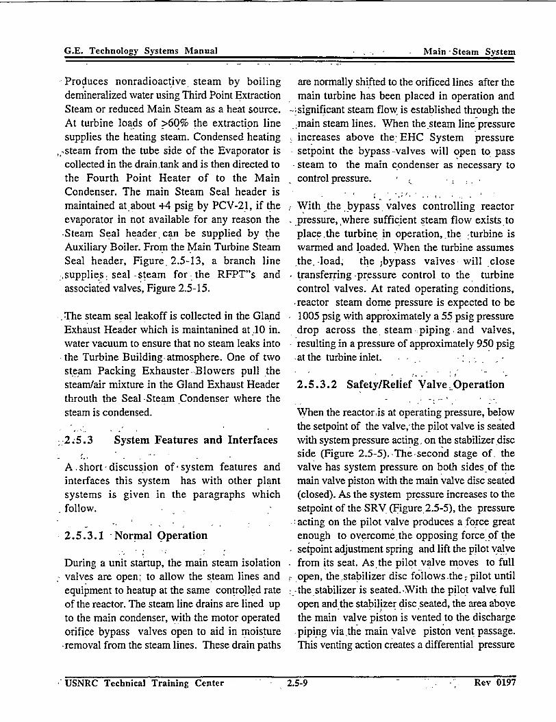
-Produces nonradioactive steam by boiling demineralized water using Third Point Extraction Steam or reduced Main Steam as a heat source. At turbine loads of >60% the extraction line supplies the heating steam. Condensed heating
,Qsteam from the tube side of the Evaporator is collected in the drain tank and is then directed to the Fourth Point Heater of to the Main Condenser. The main Steam Seal header is maintained at about +4 psig by PCV-21, if the evaporator in not available for any reason the -Steam Seal header, can be supplied by the Auxiliary Boiler. From the Main Turbine Steam Seal header, Figure, 2.5-13, a branch line supplies seal -steam for -the RFPT"s and associated valves, Figure 2.5-15.
-.The steam seal leakoff is collected in the Gland Exhaust Header which is maintanined at '10 in. water vacuum to ensure that no steam leaks into the Turbine Building- atmosphere. One of two steam Packing Exhauster-.Blowers pull the steam/air mixture in the Gland Exhaust Header throuth the Seal Steam Condenser where the steam is condensed.
--2.5.3 System Features and Interfaces
A. short, discussion of system features and interfaces this system has with other plant systems is given in the paragraphs which follow.
2.5.3.1 Normal Operation
During a unit startup, the main steam isolation valves are open- to allow the steam lines and equipment to heatup at the same controlled rate of the reactor. The steam line drains are lined up to the main condenser, with the motor operated orifice bypass valves open to aid in moisture
-removal from the steam lines. These drain paths
are normally shifted to the orificed lines after the main turbine has been placed in operation and
-.!significant steam flow is established through the main steam lines. When thesteam line pressure increases above the' EHC System pressure setpoint the bypass -valves will open to pass steam to the main condenser as necessary to control pressure. ,
With the bypass, valves controlling reactor pressure, where sufficient steam flow exists to place the turbine in operation, the turbine is warmed and loaded. When the turbine assumes the. load; the :bypass valves, will close transferring -pressure control to the turbine control valves. At rated operating conditions, ,reactor steam dome pressure is expected to be 1005 psig with approximately a 55 psig pressure drop across the steam piping and valves, resulting in a pressure of approximately 950 psig ,at the turbine inlet. • - -
2.5.3.2 Safety/Relief Valve Operation
When the reactornis at operating pressure, below the setpoint of the valve,-the pilot valve is seated with system pressure acting, on the stabilizer disc side (Figure 2.5-5). The -second stage of, the valve has system pressure on both sides of the main valve piston with the main valve disc seated (closed). As the system pressure increases to the setpoint of the SRV (Figure 2.5-5), the pressure acting on the pilot valve produces a force great enough to overcome the opposing force of the
- setpoint adjustment spring and lift the pilot valve from its seat. As the pilot valve moves to full
_open, the~stabilizer disc follows the, pilot until -the stabilizer is seated. -With the pilot valve full open and the stabilizer disc seated, the area above the main valve piston is vented to the discharge , piping via the main valve piston vent passage. This venting action creates a differential pressure
USNRC Technical Training Center 2.5-9 Rev 0197- Rev 0197
G.E. Technology Systems Manual Main -Steam System
."USNRC Technical Training Center 2.5-9
G.E. Technolo2y Systems Manual Main Steam System
across the main valve piston', system pressure below the piston and drywell pressure above, causing the main valve to lift (open). The main valve'.piston is sized such that the resultint opening force is greater than the combined spring load and' hydraulic seating force. The stabilizer disc is designed to control the valve blowdown and reset pressure, by holding the pilot open until the proper reclosing pressure is reached. The stabilizer chamber is connected, by a passage, to the inlet side of- the maifn valve. The stabilizer disc will seat when the pilot- lifts. The differential pressure across the stabilizer disc is sufficient to hold the pilot open; however, as system pressure decays, the differential pressure across the stabilizer disc 'decreases until the setpoint adjustment spring becomes the controlling member causing the pilot valve to reseat. Once the pilot valve has reseated, leakage of system fluid past the main valve piston and the stabilizer disc repressurizes the main valve chamber. When steam pressure equalizes across the main valve piston, the'opefiing force is cancelled and permits the main valve spring and hydraulic flow forces the main valve to close. Once closed, the additional hydraulic seating force, due to system pressure acting'on the main valve disc, seats the main valve tightly and prevents leakage.
In the' relief mode -of operation, pneumatic pressure is applied to an air (or N2) actuator by energizing a solenoid operated valve. The air actuator -mechanically- positions the pilot assembly to depressurize the top of the main valve piston causing the main valve to open. The solen6ids are energized by switches located in the control room. This type of'-arrangement provides the control room operator with a means to 'operate any of the 11"* safety/relief valves.
-Seven of the eleven safety/relief valve solenoids can also be energized by actuation of the
"*Automatic Depressurization System logic (ADS, Sectibn 10.2)
2.5.3'.3 System Interfaces
The interfaces this system has with other plant systems are discussed in the paragraphs which follow.
Reactor Vessel System (Section 2.1)
The Main Steam Sstem delivers steam from the reactor vessel to the' various steam loads, vents noncondensible gases from the reactor vessel head area, and provides overpressure protection for the reactor vessel.
Recirculation Flow Control System (Section. 7.2)
The Main Steam System provides a turbine firist
stage pressure signal to the EOC-RPT circuit.
Reactor Protection System (Section 7.3)
The Reactor Protection System uses MSIV closure, turbine stop valve closure, and turbine control valve fast closure signals to initiate reactor scrams and preserve fuel cladding integrity.
Turbine first stage pressure is used to provide a scram bypass for stop valve closure or control valve fast closuie if the pressure is <25% of rated (equivalent to <30% thermal power).
Condensate and Feedwater System (Section 2.6)'
The reactor feed pump turbines uses steam from the outlet of the moisture separator/reheaters and/or steam line equalizing header as an energy
USNRC Technical Training Center 2.5.10 Rev 0197Rev 0197
G.E., Techno'logy" Systems Manual '" 'Main Steam System
USNRC Technical Training Center 2.5-10
G.E. Technology Systems Manual Main, Steam System
source. Extraction steam from the main turbine is used to heat the feedwater.
Reactor Core Isolation Cooling System (Section 2.7)
The Reactor Core Isolation Cooling System uses steam from the 'A' steam line as the driving force for its turbine.
High Pressure Coolant Injection System (Section 10.1)
The High Pressure Coolant Injection System uses steam from the 'A' steam line as the driving force for its turbine.
Electro Hydraulic Control System (Section 3.2)
The Electro Hydraulic Control (EHC) System controls the operation of the bypass valves and turbine valves to control reactor pressure and turbine generator load.
Offgas System (Section 8.1)
The Offgas System uses main steam to drive the steam jet air ejectors.
Liquid Radwaste System (Section 8.2)
The Liquid Radwaste System uses main steam to heat the radwaste steam generator.
Automatic Depressurization System (Section 10.2)
The Automatic Depressurization System (ADS) uses seven of the eleven safety/relief valves to make up one of the four emergency core cooling systems (ECCS).
Feedwater Control System (Section 3.3)
-The Feedwater Control System uses steam flow signals from the steam line flow restrictors as part of the three element level-control. network and for indication.
Nuclear Steam Supply Shutoff System. (Section 4.4)
The Nuclear Steam Supply: Shutoff, System isolates the Main Steam System when required.
2.5.3.,4 PRA Insights
Parts of the Main Steam System are a major contributor to core damage frequency for several cut set sequences. The .MSIVs are listed as a contributor because their closure on loss of power would isolate the steam supply to the reactor feedwater pumps with a resulting loss of makeup to the reactor vessel. Also with the MSIV closure, the decay heat would then be transferred to the water in the suppression pool. The SRVs are listed because if a SRV opens and fails to reclose the result will be a loss of vessel inventory. The SRVs are also listed along with human error as a contributor.
Failure to initiate ADS would prevent injection to the reactor vessel by low pressure systems during a station blackout sequence.
2.5.4 Summary
Classification - Power Generation System
Purposes - To direct steam from the reactor vessel to the main turbine and other steam loads, provide overpressure protection for the reactor
USNRC Technical Training Center - 2.5-11 Key UI�J1USNRC Technical Training Center
G.E. Technology Systems ManualIv Main, Steam -System
Rev- 0197-2.5-11

G.E. Technology Systems Manual Main Steam System
coolant system, and direct steam to certain safety systems.
Components - Safety/relief valves;, flow restrictors; MSIV's; steam line drainis;'bypass valves; turbine stop valves; turbine control valves; main turbine- moisture separator/reheaters; combined intermediate valves; steam seal system.
System Interfaces - Reactor Vessel System; Recirculation Flow Control System; Reactor Protection System; Condensate and Feedwater System; Reactor Core Isolation Cooling System; High Pressure Coolant Injection System; ElectroHydraulic Control System; Offgas System; Liquid Radwaste System; -,Automatic Depressurization System; Feedwater Control System; Nuclear Steam Supply Shutoff System.
USNRC Technical Training Center 2.5-12 - Rev 0197
I

G.E. Technology Systems Manual Main Steam System
Table 2.5-1 Safety/Relief Valve Setpoints
USNRC Technical Training Center 2.5.13 Rev 0197
VALVE NUMBER JSETPOINT
RV-092 A 1125 PSIG
RV-092 B 1135 PSIG
RV-092 C 1115 PSIG
RV-092 D 1115 PSIG
RV-092 E 1125 PSIG
RV-092 F 1115 PSIG
RV-092 G 1115 PSIG
RV-092 H 1125 PSIG
RV-092 J 1135 PSIG
RV-092 K 1125 PSIG
RV-092 L 1135 PSIG
2.5-13
G.E. Technology Systems Manual M~ain Steam System
Rev 0197__m
USNRC Technical Training Center

To Suppression Pool
/1T1
SFWCS Typical , NSSSS) for alt 4 lines
To HPCI To RCIC Turbine Turbine
Typical of 2
Typical of 4
To D/W Equip. Drain Sump
81D
To Suppression Pool Drywell
CD CYD CO' WJ
Figure 2.5-1 Main Steam System
Bypass Valve Manifold
0000
/ Main ýConde~nser"

U, C- 1294
0 0
E cin
E
CD
as 0)
Eil
UZ2
2.5-17

Main Steam Distribution
Header
1 Moisture I F Seperator A (2nd Stage)
RFP Turbine B HP Stop Valve
Moisture 11 Seperator
Building Service Heat Exchangers
Off-Gas Preheater
From
To Off Gas Booster Air Ejector
To Main Condenser ý RWS/G
1st Stage Air Ejector 1A
S1st Stage Air Ejector 1A
2st Stage Air Ejector 1 A
2st Stage Air Ejector 18
1B
Figure 2.5-3 Auxiliary Steam Headers
2.5-19
0194
m Extraction Steam
Steam

main stem nMain Turbine fM=O AO ID L DisribuionStop Valves
D OWED D Header
N)ED
TooMainlCondense
-To Main Condenser
To Main Condenser
n8n
0
Figure 2.5-4 Main Steam Line Drains (0

STABI LIZER DISC
ADJUSTMENT LOT SPRING £LVE
4AIN VALVE ELOAD SPRING
INLET
ACTUATOR
VALVE DISC
Figure 2.5-5 Two Stage Target Rock Safety/Relief Valve
2.5-23
PI LOT PRELOAC
SPRING
PILOT

STABI LIZER
Figure 2.5-6 Two Stage Target Rock Safety/Relief Valve (Open)
2.5-25

AIR CYLINDER
DASH POT
•" SPRING GUIDE
ACTUATOR SUPPORT AND SPRING GUIDE SHAFT
-SPRING SEAT MEMBER STEM
BONNET BOLTS
BONNET
FIGURE 2.5-7 MAIN STEAM ISOLATION VALVE
PISTON RING
PILOT
" BALANCING ORIFICE
MAIN VALVE SEAT

SLOW CLOSURE TEST SOLENIOD
PNEUMATIC SUPPLY
ACCUMULATOR
PNEUMATIC SUPPLY
(1) OUTBOARD MSIV SUPPLYCONTROL AIR SYSTEM
(2) INBOARD MSIV SUPPLYNITROGEN
NOTE. SOLENIOD VALVES SHOWN ENERGIZED, VALVE OPEN
FIGURE 2.5-8 MAIN STEAM ISOLATION VALVE (OPEN)
PNEUMATIC CYLINDER
- PISTON

* PNEUMATIC SUPPLY
ACCUMULATOR
PNEUMATIC SUPPLY (I) OUTBOARD MSIV SUPPLY*
CONTROL AIR SYSTEM
(2) INBOARD MSIV SUPPLYNITROGEN
NOTE: SOLENIOO VALVES SHOWN
DENERGIZED. VALVE CLOSED.
FIGURE 2 5-9 MAIN STEAM ISOLATION VALVF (CI ocFni
SLOW CLOSURE TEST SOLENIOD
PNEUMATIC CYLINDER
PISTON

Pneumatic 0396 Supply (N)
Accumulator I
A~j B 1,25 vDC -- •• Vent
ADS Logic "B" -S Remote --- Shutdown I IPanel
Backup Control 4--- - ---------- - Transfer Switch I 7
IADS Logic "An Room
Reactor Vacuum Vessel Breakers
~Concrete
Pressure Suppression
Chamber
Figure 2.5-10 Safety/Relief Valve Arrangement
2.5-33

STEAM OUTLET
SECOND STAGE TUBE BUNDLE
SHELL
IMPINGEMENT BAFFLE
MOISTURE SEPARATOR / STEAM INLET DRAIN
Figure 2.5-11 Moisture Separator Reheater (End View)
FIRST STAGE TUBE BUNDLE
"1
C"'
0)

To Radwaste Steam Generator
To Main Turbine Seating Steam
- Auxiliary Boilers
I From Condensate System
To 4th. Point Feedwater Heater
Condenser
N35-1oH (open @26">NWL In DR tank)
Steam Generator
C.0
4J
Figure 2.5-12 Steam Seal Supply
0 \0 a,

(11V
BPV 2I 2 __Exhaust Header
BPV _ Exhaust Header
BPV Steam v [•Exhausto
To 4th Point H.P. Turbine Extraction
Exhaust
Condenser Condenser Condensate SealoSteam
System Condenser
Figure 2.5-l3Main Turbine Sealing Steam0�
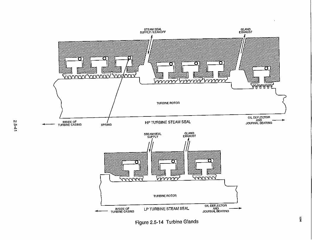
INSIDE OF I STURBINE CASING SPRING
LP TURBINE STEAM SEAL
Figure 2.5-14 Turbine Glands
N01

From Main Turbine Steam Sealing
To Steam Packing Exhauster
To Condenser
Figure 2.5-15 Feed Pump Turbine Steam Seal0 10
*01 (A)

Boiling Water Reactor GE BWR/4 Technology
Technology Manual
Chapter 2.6
Condensate and Feedwater System

G.E. Technology Systems Manual Condensate & Feedwater System
Table-of Contents
2.6 CONDENSATE AND FEEDWATER SYSTEM ....................................................... 1
2.6.1- Introduction .................................................................................... 1
2.6.2 Component Description ". : "................... 1
2.6.2.1 Main Condenser ........................................... 2
2.6.2.2 Condenser Hotwell ............................................. 3
2.6.2.3 Condensate Pumps ......................................... 3
2.6.2.5 Steam Jet Air Ejector Condenser ....................... ........................ 3
2.6.2.6 Steam Packing Exhauster Condenser ............ .................. 3
2.6.2.7 Condensate Demineralizers .............................................................. 3
2.6.2.8 Exhaust Hood Spray Line Flow Paths ................................................ 5
2.6.2.10 Condensate Booster Pumps ............................................................ 5
2.6.2.11 Low Pressure Feedwater Heating ....................................................... 5
2.6.2.12 Drain Coolers ............................................................................ 5
2.6.2.13 Low Pressure Feedwater Heaters ....................................................... 6
2.6.2.14 Heater String Isolation Valves ......................................................... 6
2.6.2.15 Reactor Feedwater Pumps .............................................................. 6
2.6.2.16 High Pressure Feedwater Heaters ...................................................... 7
2.6.2.17 Feedwater Discharge Piping ........................................................... 7
2.6.3 System Features and Interfaces ................................................................. 7
2.6.3.1 Normal Operation ......................................................................... 7
2.6.3.2 System Startup ........................................................................... 8
2.6.3.3 Hotwell Level Control ................................................................. 8
2.6.3.4 Feedwater Heater Extraction Steam .................................................... 8
2.6.3.5 Feedwater Heater Drains ............................................................... 10
2.6.3.6 System Interfaces ....................................................................... 11
2.6.4 Summary ......................................................................................... 11
-USNRC Technical Training Center 2.6-i Rev 0197

G.E. Technology Systems Manual Condensate & Feedwater System
List of Figures 2.6-1 Condensate System ............................................................................ 13
2.6-2 Feedwater System .............................................................................. 15 2.6-3 Condenser Flow Paths ......................................................................... 17
2.6-4 Typical Horizontal Feedwater Heater ......................................................... 19
2.6-5 Typical Vertical Feedwater Heater ........................................................... 21
2.6-6 Reactor Feedwater Pump Turbine ............................................................. 23
2.6-7 Reactor Feedwater Pump Oil System ........................................................... 25 2.6-8 Moisture Separator Reheater .................... : ............................................ 27 2.6-9 Extraction Steam ................................................................................... 29
2.6-10 Heater Drains Flow ............................................................................ 31
USNRC Technical Training Center 2.6-u Rev 0197
- I
USNRC Technical Training Center 2.6-ii I Rev 0197
E~i Technologyv Systems ManualCodsae&FdatrSsm
2.6 - CONDENSATE AND FEEDWATER SYSTEM
-Learning Objectives :
1. State the system's Purposes. 2. Explain how the system accomplishes its
purpose. 3. Place ,the, -following major system
.components in flow path order and explain the purpose of each: a. Main Condenser
- b., Condensate Pumps -c. Condensate Demineralizes -e.- Condensate booster pumps d. Low pressure heaters f. Feedwater pumps g. High pressure heaters
, - h. Reactor vessel 4., Explain the interfaces this system has with
the following systems: or components: a. Reactor Vessel System b. Reactor Core Isolation Cooling System
Sc. High Pressure Coolant Injection System d: .Reactor Water Cleanup System
-e. .Feedwater Control System
f. Main Steam System _g. Offgas System.
2.6.1 Introduction
--The purposes of the Condensate and Feedwater
-System are to condense steam, collect drains,
remove noncondensible gases, purify, -preheat,
pump water from the main condenser ,to the
reactor vessel,ý to provide a path; for certain
safety related systems to inject water into the
reactor vessel. ..
The function classification of the Condensate and
Feedwater System is that of a power generation system. , ".
The Condensate and Feedwater System, shown in Figures 2.6-1 and 2.6-2, is an integral part of
the plant's conventional regenerative steam cycle.
The steam exhausted -in from the low pressure
turbines is condensed in the main condenser and collected in the condenser hotwell, along with
various equipment drains. The condensate that is
.collected in the hotwell is removed by the
condensate pumps. The condensate pumps
provide the driving force for the condensate which flows through the ,steam jet air, ejector
condensers,, and steam packing exhauster
condenser performing a heat removal function.
At this point the condensate is directed to the
condensate demineralizers and, through the
process of ion exchange, impurities are removed.
After the demineralizers, booster pumps are used to maintain the driving force of the condensate
flow through strings of low pressure feedwater
heaters. The feedwater pumps then take the
condensate flow and further increase the pressure
to a value above reactor pressure. The amount of
feedwater flowing to the reactor -vessel, is
controlled by varying the speed of the turbine
driven reactor feed pumps. The discharge of the
feedwater pumps is directed to the high pressure
feedwater heater strings -for the final stage of
feedwater heating. Two feedwater lines penetrate
-the primary containment and then further divide
into a total of four.penetrations which enter-the reactor vessel with each supplying feedwater to a
_,feedwater sparger.
The feedwater spargers distribute the flow of feedwater within the vessel annulus area.
2.6.2 Component Description
The components that comprise the Condensate -and Feedwater System are discussed in the
J following paragraphs.
'--- PVf7
2.6-1-" USNRC Technical Training Center
-Condensate -& Feedwater System
Rev 03 N• V

G.E. Tecnolgy Sstes MaualCondensate &Feedwater Svsteni
2.6.2.1 Main Condenser
The main condenser; shown in Figure 2.6-3, consist of two deaerating, single pass, single pressure, radial flow type surface condensers with divided water boxes. Each of the condensers is located beneath one of the two low pressui'e turbines with the condenser tubes running perpendicular to the turbine-generator axis. The main condenser receives cooling water from the Circulating Water System. 'Circulating water flows through the condenser tubes, condensing the low pressure turbine exhaust steam surrounding the tubes.
During normal operation, steam from the low pressure turbine is exhausted directly downward into the condenser shells through exhaust openings in the turbine casing.
As turbine exhaust flows downward the area increases, reducing the velocity of the exhaust steam. By lowering the exhaust 'steam velocity, the vibration and er6sion experienced-by the upper rows of tubes is minimized.
The condenser neck section of each condenser directs low pressure turbine exhaust steam to the condenser tube section. In addition to directing steam, the 'condenser neck- houses two low pressure feedwater heiters,` a drain cooler, and extraction steam piping. The low pressure feedwater heaters, drain cooler, and extraction steam piping that are'located in the condenser neck are lagged with stainless'steel insulating panels. The insulating panels minimize heat loss to the condenser.
A rubber belt type expansion joint is installed between the low pressure turbine' and the condenser neck to permit differential expansion. The condenser section internals are arranged to
circufluent the low pressure turbine exhaust steam from the outer circumference of the tube bundle toward the center, where most of the steam is condensed. The remaining mixture'of noncondensible gases and water vapor are then directed to the air cooler section.
The air cooler section consists of a vent duct and tube bundle enclosed by the air cooler baffle. The air cooler baffle is open at the bottom to direct all the remaining noncondensible gases and water vapor upward through the tube bundle. In passing through the tube bundle the mixture of noncondensable gases and water vapor is cooled, reducing its volume. The remaining mixture flows toward the colder end of the air cooler and the vent duct outlet.
The vent duct directs the offgas steam mixture to the offgas penetrations where it will be further processed (Offgas System, Section 8.1).
The cdndenser units also serve as a heat sink for several other flows; such as exhaust steam from the reactor feed pump turbines, turbine bypass steam, cascading low pressure heater drains, air ejector condenser drains, seal steam condenser drains and the feedwater heater shell,,operating vents. Other flows to the condenser sections occur periodically from the startup vents of the condensate pumps, condensate booster pumps, reactor feed pumps, low pressure feedwater heater shell and minimum recirculation flows from the reactor feed pumps, condensate booster pumps, condensate' pumps, etc. Most of these return lines to the condenser either contain steam or a mixture of steam and water vapor and are located below the tube bundle to, prevent overheating tubes, disturbing the main turbine exhaust- flow, or overheating the turbine. An exception if this is the turbine bypass steam, which enters the condenser above the bundles
U�N KC Technical Training Center 2.6-2 Rev 0397
I-
G.E.' Techno'logy Systems ManualI
USNRC: Technical Training Center 2.6-2 Rev 0397

G.E. Technology Systems Manual Condensate & Feedwater System
due to the large quantities of steam flow which might be encountered (up to 25% of rated steam flow).
,To ensure equal pressure between the condenser shells, cross-connect pipes are provided between the upper portions of the condenser tube nest.
2;-6.2.2, Condenser Hotwell
The condenser hotwells are incorporated in the bottom of each condenser shell and serve as
-collection points for all condensate. The hotwell for each shell is integral with, and a continuation of, the condenser shell side plates. The hotwells are tied together with 24 inch equalizing lines to ensure equal level in both hotwells.,
-,Each hotwell is designed to store a sufficient quantity of condensate to provide a minimum of 2 minutes 'effective retention of all condensate entering the hotwell for radioactive decay of N 16 (tl/2= 7.11 seconds). Retention time is ensured from normal water level to minimum operating
Slevel by use of a horizontal collector plate under the tube bundles. The plate directs the condensate to the'end of the hotwell opposite the condensate "pump suction pipe. Additional storage volume, over and above the specified storage capacity, is
- designed into the hotwell. With these provisions, the shortest possible path from the collector plate to the condensate outlet takes two minutes at a minimum operating level.
,2.6.2.3 Condensate Pumps
Two condensate pumps provide the motive force required to remove water from the condenser hotwell to the condensate booster pumps at sufficient pressure to ensure adequate net
,; position suction head.
The condensate pumps are three stage pumps with a capacity of 12,153 gpm each at a discharge pressure of -200,psig. Each of the 'condensate pumps take •condensate from a
- common supply header via a manually operated valve and delivers it to a common discharge header.
2.6.2.5 Steam Jet Air Ejector Condenser
The steam jet air ejector (SJAE) condensers are provided to condense the steam exhausted from the first stage SJAE (Offgas System,, Section 8.1) and drain the resultant'condensate back to the, condenser hotwell. :Condensate flow is normally aligned 'to both SJAE condensers
' though one set is in service at a time.
A line in parallel with the SJAEs and the steam packing exhauster condenser (SPEC) contains a pressure control valve used for ensuring proper flow through the SJAEs and the SPEC.
2.6.2.6 Steam:Seal Exhauster Condenser
The purpose of the, steam seal iexhauster ,;condenser is to condense the leak-off steam from -main'and 'reactor feed pump turbine seals. The steam seal exhauster condenser is in the flow path with the SJAE condensers, FCV-22 maintains a constant 10 Kgpm flow through the SSEC for optilmum operation. Operation of the steam side can 'be found in the Main Steam System, Section 2.5.
•. 2.6.2.7 Condensate Demineralizers
- The function of the condensate demineralizers is to remove dissolved and suspended impurities from the condensate. -The condensate
USNRC Technical Training Center 2.6.3 Rev ' 0397
G.E. Technology Systems Manual Condensate & Feedwater System
USNRC Technical Training Center 1 2.6-3 Rev "0397

G.E. TaCondensate & Feedwater Sv.tem
demineralizers, in conjunction with the Reactor Water Cleanup (RWCU)' System (Section 2.8), serve to purify the steam cycle water and maintain the reactor water quality limits under startup and normal operating conditions. The condensate demineralizers also may, depending on the magnitude of the contamination, allow an orderly shutdown of the reactor during abnormal conditions such as condenser tube leakage or contamination from other sources.
The demineralizers consist of eight units"and regeneration facilities to chemically regenerate the cation and anion mixed'bed resins: -The eight units are arranged in parallel. Seven of the units are heeded for 100% power operation, one remains in standby. The demine'ralizers remove both dissolved and suspended solids from the condensate. These solids may be corrosion products from the steam and Condensate systems or solids carried in by makeup water.
Condensate enters the in service demineralizers through motor operated inlet valves. The inlet valves are operated with pushbutton switches at the local control panel.- Deminerializer effluent flows to the post strainer through a flow control valve. The flow control valve is positioned by the condensate demineralizer flow balancing system. Post-strainers retain any resin-material which might break through the retention elements in the demineralizer outlet header. A pressure switch is provided to give a high strainer differential pressure annunciator (9 psid) on the local control panel: At that time the associated demnineralizer must be removed from operation and the strainer manually backwashed. Condensate flow through the various in service demineralizers is regulated by a flow balancing system. The purpose of the flow balancing system is to ensure that all vessels in service share the flow equally. The design flow control
range for each demineralizer is 1560 GPM minimum' to 3430 GPM maximum. At the same time, the system must introduce as little a pressure drop as possible through action of the control valves in the system. A flow balancing system is needed because the resin beds in the service vessels have been regenerated at different times, and being at different points in their service run, show different resistance 'to flow. This variation in pressure drop across the beds of the different vessels is made up for by the flow control valves which are open further for the service vessel with the greatest pressure drop across its bed and relatively less open for the vessels having the least resistance to flow.
Total pressure drop across the eight demineralizers is provided at the local control panel. When the total pressure drop across the demineralizers exceeds 50 psid an annunciator alarms on. the local control panel. Individual demineralizer differential pressure is also provided for indication of depleted resin beds. A bypass valve is provided to bypass the condensate demineralizers in an emergency. If differential pressure across the condensate demineralizers increases to 50 psid, then. the condensate demineralizer bypass valve opens and the condensate, inlet and outlet valves isolate. When the bypass valve has automatically opened, it must be manually closed from the local control panel. The bypass valve is of a size to allow full condensate flow. The demineralizers should also be manually bypassed when the temperature of the condensate entering the demineralizers exceeds 130°F.
This administrative limit protects the resins from melting as temperatures approach 1500 to 1600F.
A demineralizer is removed from service when its resin is depleted as indicated by high differential
USNRC Technical Training Center 2.6.4 Rev 0397Rev 0397
G.E. Technology Systems' Manual
USNRC Technical Training Center 2.6-4
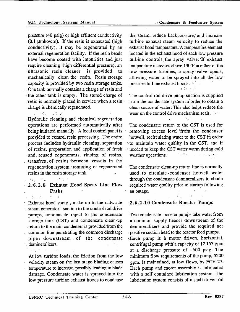
G.E. Technology� Systems Manual Condensate & Feedwater System
pressure (40 psig) or high effluent conductivity (0.1 jtmho/cm). If the resin is exhausted (high conductivity), it may be regenerated by an external regeneration facility. If the resin beads have become coated with impurities and just require cleaning (high differential pressure), an ultrasonic -resin cleaner is provided to mechanically clean the resin. Resin storage capacity is provided by two resin storage tanks. One tank normally contains a charge of resin'and
- the other tank is empty. The stored charge of -'resin is normally placed in service when a resin -charge is chemically regenerated.
Hydraulic cleaning and chemical regeneration operations are performed automatically after being initiated manually. A local control panel is provided to control resin processing.. The entire process includes hydraulic cleaning, separation of resins, preparation and application of fresh
,and. reused regenerants, rinsing of resins, -transfers -of resins -between vessels in the
Sregeneration -system, remixing of regenerated resins in the resin storage tank.
.- 2.6.2.8 Exhaust Hood Spray Line Flow Paths
Exhaust hood spray, make-up to the radwaste steam generator, suction to the control rod drive pumps, condensate reject to the condensate storage tank (CST) and condensate clean-up ,return to the main condenser is provided fromnthe common line penetrating the common discharge
-pipe: downstream of the condensate demineralizers.
At low turbine loads, the friction from the low velocity steam on the last stage blading causes temperature to increase, possibly leading to blade damage. Condensate water is sprayed into the low pressure turbine exhaust hoods to condense
the steam, reduce backpressure,- and increase turbine exhaust steam velocity to reduce the exhaust hood temperature. A temperature element Jlocated in the exhaust hood of each low pressure turbine controls the spray valve. -If exhaust
temperature increases above 130'F in either of the low pressure turbines, a spr'ay'valve opens, allowing water to be sprayed into all the low pressure turbine exhaust hoods.-.
The control rod drive pump suction is supplied from the condensate system in order to obtain a clean source of water:This also helps reduce the wear on the control drive mechanism seals.
The condensate return to the CST is used for removing excess level 'from the condenser hotwell, recirculating water to the CST ini order
'to maintain' water quality in the CST, and if needed to keep the CST water warm'during cold weather operations.
The condensate clean-up return line is normally used, to circulate condenser. hotwell water through the condensate demineralizers to obtain required water quality prior to startup following an outage.
2.6.2.10 Condensate Booster Pumps
Two condensate booster pumps take water from a common supply header downstream of the demineralizers and provide the required net
,positive suction head to the reactor feed pumps. 'Each pump is a motor driven, horizontal, centrifugal pump with-a capacity of 12,153 gpm at a discharge pressure of -600 psig. The minimum flow requirements of the pump, 5200 gpm, is maintained, at low flows, by FCV-27. Each pump and motor assembly is lubricated with a self contained lubrication system. The lubrication system consists of a shaft driven oil
USNRC Technical Training Center 2.6.5 Rev 0397
G.E. Technology, Systems Manual -, Condensate & Feedwater System
Rev 0397USNRC Technical Training Center 2.6-5

G.E.Tecno~oy Sstem MaualCondensate &Feeriwater Svstem
pump, a motor driven auxiliary oil: pump, an oil filter and cooler. Cooling water for the oil system is provided from the turbine building closed loop cooling system. Both booste& pumpshave a low suction pressure trip at 35 paig, the A pump is time delayed 20 seconds while the B pump is time delayed 45 seconds.
2.6.2.11 Low Pressure Feedwater Heating
Low pressure feedwater heating increases plant efficiency while at the same time minimizing turbine blade damage from high moisture content steam. High moisture content steam, extraction steam, from various low pressure turbine stages is. piped to feedwater heaters where the steam condenses to form heater drain water. Use of feedwater as a heat sink for the extraction steam, the feedwater temperature is increased to approximately 300°F.
The low pressure feedwater, heaters are identically arranged in two parallel strings with each& string consisting of an- inlet and outlet isolation valve, one drain cooler, and five low pressure feedwater heaters. Additionally, each string of feedwater heaters receives extraction steam from a separate low pressure turbine.
2.6.2.12 Drain Coolers
The drain coolers are water to iwater heat exchangers used to remove the last amount of available heat energy from the heater drains prior to discharge to the condenser hotwell.
At full power operation, feedwater enters the drain cooler at 103°F.'
I
2.6.2.13 Low Pressure Feedwater Heaters
The feedwater- heaters are internally constructed to accommodate three flow paths: feedwater, extraction steam; and heater drains. Feedwater enters the heater at the water box and is directed to stainless steel u-tubes via a water box divider plate. Once inside the tubes the feedwater passes through an internal drain cooler section, except heater number 5, where it cools the heater drain water. After passing through the drain cooler section, the fe'edwater absorbs energy from the heater drain water located in the bottom of the heater. The feedwater makes a turn in the' u'section of the' tubes and enters the extraction steam section. The feedwater passes through the steam section where it absorbs heat energy prior to entering the water box and exiting the heater.
Extraction steam enters the feedwater heater via two penetrations in the upper section of the heater. Upon entering the heater, the steam is directed at right angles to the point of entry by impingement plates. The impingement plates along with internal baffling forces the steam to flow around the upper rows of feedwater heater tubes. When the extraction steam gives up its latent heat of vaporization to the feedwater, the steam condenses and falls to the bottom of the heater forming the heater drains.
The heater drains accumulate in the bottom of the heater where they flow around the feedwater heater tubes on the way to the drain cooler section. Once inside the drain cooler section, the drains follow a tortuous path via a baffle arrangement to transfer the last available energy to the feedwater. The drain cooler section is employed to limit the amount of heater, drain water that flashes into steam when cascading. to a lower pressure heater.
USNRC Technical Training Center 2.6.6 Rev 0397
G.E. Technologzy Systems Manualm
USNRC Technical Training Center 2.6-6 Rev 0397

G.E. Technolo�v Systems Manual Condensate & Feedwater System
. 2.6.2.14 Heater String Isolation Valves
-The ,heater string isolation valves are motor operated valves with the capability of both automatic and manual closure. The heater string is also equipped with a bypass valve. Automatic closure of both the inlet and outlet valves and opening of the heater bypass valve is initiated upon detection of a heater high water level in that string. The automatic isolation of a heater string provides turbine protection from water intrusion caused by backing up of water from the heater into the extraction steam line. Manual operation of the isolation valves is provided for maintenance of the heaters.
2;6;2.15 Reactor Feedwater Pumps
Two reactor feedwater pumps (RFP's) take heated feedwater from the outlet of-the low pressure feedwater- heaters and provide the driving force necessary to supply water to the
-reactor -vessel. Each RFP is a horizontal, -centrifugal,, single stage ,pump driven by a
variable speed steam turbine with a designed flow rate of 14,000 gpm at a total discharge head of 1130 psig. Each pump is -rated at 67% of system capacity
Motive force is supplied by a six stage, single direction, dual admission condensing turbine. Steam turbine driven pumps are used to increase overall plant efficiency. The RFP turbine (RFPT) is an impulse/reaction type turbine with a single thrust bearing. Each turbine is rated at 8,500 horsepower at 5500 rpm (rated speed), and is equipped xwith overspeed protection and bearing
Svibration detectors. Both pumps have a low suction pressure trip at 250 psig, the A pump is time delayed 8 seconds while the B pump is time delayed 25 seconds.
Each turbine is equipped with two sets of stop and control valves (Figure 2.6-6). One set of valves regulates low pressure steam extracted from the discharge side --of the moisture
•,separator/reheaters, in theMain Steam System (Section 2.5). This is the normal steam supply to the turbine.
Steam from the moisture separator/reheaters flows through the LP steam block valves through the LP stop valves, and the five LP control valves, then'the turbine. After passing through the turbine the steam is exhausted to the main condenser. The high pressure stop valves and high pressure control valve are supplied steam from the main steam equalizing header through the HP steam block valves. The high pressure and low pressure stop valves provide for rapid isolation of the steam supply to the RFPT for turbine protection.
Control of the five low pressure control valves and the single high pressure control valve is from a linkage arrangement which sequentially opens the valves. The five low pressure control valves open in sequence, followed by thesingle high pressure control valve. .The linkage is arranged so that the high pressure valve does not
:throttle open until the last low pressure valve is fully open. -Thus; the turbine will use', low pressure steam in preference to the high pressure steam whenever it is available.
-The stop and control valves are hydraulically operated by control oil supplied from the RFPT oil system and regulated by the Feedwater
.Control System (Section 3.3).
USNRC Technical Training Center 2.6-7 Rev 0197USNRC Technical Training Center
G.E. Technology Sy'stems Manual -Condensate & Feedwater System
2.6 -7 Rev 0197

G.E. Technology Systems ManualCodna- 9, r-' nA. # J C
2.6.2.16 High Pressure Feedwater, Heaters
The high pressure feedwater heaters represent the last stage of feedwater heating. High pressure feedwater heating consists of two identical parallel strings of heaters and valves. Each string consists of a feedwater heater and an inlet and outlet isolation valve. As with the low pressure heater string the high pressure heaters are equipped with a bypass valve. The high pressure heaters operate in the same manner as the low pressure heaters. The term high, pressure originates from the location of the heaters in the condensate and feedwater system and the high pressure extraction steam used for heating. Both feedwater lines contain flow elements after the outlet isolation valve.
2.6.2.17 Feedwater Discharge Piping
The feedwater piping downstream of the high pressure feedwater heaters consists of a common line that branches into two separate lines. Both feedwater lines contain an outboard isolation valve, a testable check valve, and an- inboard manual isolation; and penetrations for certain safety related systems. -Each feedwater line in turn then penetrates the primary containment and branches into two separate. lines, which are welded to the safe end nozzle penetrations on the reactor vessel.
In addition to performing a safety function, the feedwater lines provide a path for the Reactor Water Cleanup System (Section 2.8), the Reactor Core Isolation Cooling System (Section 2.7), and the High Pressure Coolant Injection System (Section 10.1) to return water to the reactor vessel.
2.6.3 System Features and Interfaces
A short discussion of system features and interfaces. this system has with other, plant systems is gi&,en in the paragraphs which follow.
2.6.3.1' Normal' Operation
The number' of condensate pumps, condensate booster pumps, and reactor feed pumps in operation depends on the plant load (i.e., MWe output). Normally. at 100% power both condensate pumps, both condensate booster pumps, both reactor feed pumps and all but one of the demineralizers are required for operation. At lower power levels, various combinations of condensate and booster pumps and rea'ctor feed pumps are used so that the pumps are operating near or at their design flow rate. In general, the flow requirements are controlled by the Feedwater Control System,, with the Condensate and Feedwater System in operation and able to meet any expected flow transients by having reserve capacity on the line, or by starting additional* pumps. The number of operating condensate pumps should always be equal to or greater than the number of operating condensate booster pumps.
2.6.3.2 System Startup
If the plant has been shutdown for maintenance for a long period of time, the condensate water quality may be low and require cleanup by the demineralizers.
The, first step is to, place the Condensate, and Feedwater System in short or long cycle cleanup modes. For short c3ycle mode of operation one condensate ,pump is started and two demineralizers are placed in service. The condensate pump removes water from the
USNRC Technical Training Center 2.6.8 Rev 0197
I
I
USNRC Technical Training Center 2.6-8 Rev 0197

G.E. TechnoIo�y Systems Manual Condensate & Feedwater System
condenser hotwell and provides the motive force -for cleanup. The-discharge of the condensate pump is directed- through the auxiliary condensers, and demineralizers.
From the common discharge header of the demineralizers the water is recycled back to the condenser via the air operated, automatically controlled, short cycle valve.
When all of the Condensate and Feedwater System requires clean up, the long cycle mode of operation is used., To accomplish long cycle. cleanup; the system is aligned to allow flow through the, low pressure feedwater heaters,
, around the reactor feed pumps via the startup ,bypass valve, and into the, high. pressure feedwater, heater strings. From the high pressure feedwater heaters,,flow is recycled back to the condenser hotwell via the startup recirculation lines located between the final heaters and the downstream heater isolation valve.
The startup bypass line also allows the condensate booster pumps to supply water to the reactor during startup operations when a feedwater pump is not required. During plant startup, feedwater is required to maintain water level in the reactor. The reactor startup bypass line level control valves are automatically
- positioned to maintain the water level, via the Feedwater Control System. At first a condensate,
"and. condensate booster pump, will, supply Ssufficient pressure and flow~to maintain level. As
-pressure-in the ,reactor increases, it becomes necessary to use another condensate booster and condensate pump to add water when required. When reactor pressure reaches approximately 350 psig, a reactor feed,pump is started in, preparation for feeding the reactor vessel. As the
-startup continues, equipment is placed in service as required.
The shell side of the feedwater heaters are automatically placed in service when the main turbine is warmed and placed in service.
2.6.3.3 Hotwell Level Control
The hotwell level control system is used to maintain a constant level of water in the condenser hotwell. It consists of level indicating controllers which control a makeup supply from
Sthe condensate storage tank (CST) and a reject back to the CST.,... ,
Whenhotwell level is-high, the hotwell level control system opens the air operated reject valve
-on the outlet of the demineralizers. This removes - water from the system, returning it to the CST, and lowers hotwell level. When hotwell level is low, makeup water is supplied from the CST through the air operated makeup valve.
Both the air operated reject and makeup valves are provided with motor operated bypass valves which are operated from the control room. These valves can' be used to provide additional flow capacity if the automatic valves should fail.
2.6.3.4 Feedwater, Heater Extraction Steam
Extraction steam provides the heat source for .'heatingothe feedwater heaters, the seal steam
evaparator, and the radwaste evaporator. Feedwater heater extraction steam 'provides for
'heating of the feedwater to improve plant efficiency. Extraction -steam and heater arrangement, are designed to supply sufficient heat to establish a final feedwater temperature of approximately 420°F.
High pressure feedwater heaters (1st point heater A/B) receive extraction steam from the Ilhigh
-USNRC Technical Training Center 2.6.9 Rev 01972.6-9
G.E. Technology Systems, Manual Condensate & Feedwater System
Rev 0197-USNRC Technical Training Center

G..Tchooy. yt. . Mna.Cnesae.Fedae Syste...
pressure turbine through extraction lines attached to the turbine casing at the fourth stage.
These 1st point heaters also receive the high temperature drain water from the first and second stage reheater drain tanks.
The low pressure heaters- (2, 3, 4,,5, and 6th point heaters) are arranged in two sets of parallel strings. Each low pressure heater is supplied with steam from its own extraction points located in one of the two low pressure turbines. The 6th point heaters are located in the exhaust trunk of the condenser. The 3rd point heaters also receive drain water from the moistufe separator drain tank. The 4th point heaters also receive drain water from the steam seal evaporator drain tank and the radwaste steam generator drain tank.
The heater drain coolers receive drain water from the 5th point heater as its heating medium.
The feedwater extraction steam system is illustrated in Figure 2.6-9. The B low pressure turbine is shown with the exitraction- steam iines to the low pressure heaters. The A low pressure feedwater heater strings are identical. Figure 2.6-9 also shows the feedwater heater extraction points.
The extraction lines to the no. 1, 2, 3, 4, and 5 point heaters are equipped with motor operated block valves which automa'cially 'close on a trip of the main turbine or on high water level in the heater. these extraction lines are also eq'uipped with air operated nonretum (NRV) check valves. The NRV valves also close on a main turbine trip or highi he ter w' ter level. The piirpose of these valves is to prevent backllow of watier or steam from entering the turbine and causing damage either by' Water induction or overspeed resulting from'reverse steam flow.'
The NRV valve' is a free swinging, gravity closing, check valve. The valve disc will open when the inlet pressure becomes slightly higher than the outlet pressure and will close when the inlet pressure becomes slightly less than the outlet pressure or a reversal of flow occurs. To ensure positive closing, a spring loaded air cylinder is installed on the outside of the valve body connected by means of a piston rod and suitable linkage to the shaft.
Under normal operating- conditions; with air pressure established ini the air cylinder, the piston is-in its top position with the closing spring compressed.- Upon' receiving a high level in a feedwater heater, the solenoid valve will deenergize and vent the air pressure from below the piston. The closing spring forces the piston downward, which in turn acts through the piston and pulls down the closing lever on the shaft and rotates the disc to its seat. The valve will remain in this position until air pressure, is again established in the cylinder and the piston moved upward or the, extraction steam pressure overcomes the cylinder spring force. Upon receiving a turbine trip, the extraction relay dump valve which is part'of the Electro Hydraulic Control Systeni (Section 3.2) will trip and vent the air off the NRV valves.
Because the 6th point heaters are located within the condenser, their extraction lines have no shutoff or check valves to isolate the heaters. The extraction steam piping to these heaters is protected from water induction by the automatic closing of the heater condensate inlet and outlet valves when high heater level is detected.
The 1st point through the 5th point feediwater heaters have air operated extraction bypass valves that are used to keep the extraction steam lines drained under various plant startup conditions. If
USNRC Technical Training Center 2.6-10 Rev 0197Rev 0197
I-
G.E.- Technology Systemfs Manual ICondensate & Feedwater System
USNRC Technical Training Center 1 2.6-10

G.E. Technology Systems Manual Condensate & Feedwater System
closed, the drain valves automatically open upon either main turbine load decrease to less than 15% .(as determined -by turbine first stage pressure), main turbine trip, or high heater water level.
All low pressure feedwater heaters have flash containment baffles provided in the heater shells to reduce the possibility of turbine overspeed from flashing of shell drains.
-.2.6.3.5 Feedwater Heater Drains
The heater drain system consists of moisture separator,- first stage reheater and second stage reheater, drain tanks, the radwaste steam generator and steam seal evaporator drain tanks, and the level control valves associated with those drain tanks and the feedwater heaters. The feedwater heater drains are only for the heater
, drains associated -with the extraction steam covered in Section 2.6.3.4. The feedwaterheater .drains are shown, in Figure 2.6-10. As the extraction steam gives up its heat to the feedwater, it condenses and is collected in the bottom of the feedwater heaters as heater drains. .Thefeedwater heaters utilize a cascading drain system with the drain flow from the highest pressure and -temperature heaters -flowing successively to the next lowest pressure heater.
Condensed extraction steam from the 1st point high pressure feedwater heaters is drained through normal drain valves to the 2nd point heater. An emergency drain line to the condenser is provided to prevent heater flooding in the event of high heater level.
The remaining low pressure heaters are provided with a cascading drain system as described for the 1st point heater. The exception to this pattern is that the 5th point heater has a direct drain to a
heater drain cooler. One heater drain cooler is provided for each heater string: Then the heater drain cooler drains to the main condenser. The 6th point heater has a direct drain to the main condenser
During a level transient, if the normal drain flow path and emergency drain flow path are unable to maintain the proper heater levels, the motor operated extraction block valves and NRV valves close for heaters 1, 2, 3, 4, or 5 and the condensate inlet and outlet valves, close for heaters 1 or heater 2 through 5. High heater water level also opens the heater extraction steam bypass valves.
The moisture separator drain tank receives drains from the moisture separator -section, of the moisture separator reheater (MSR), vents to the MSR, and drains to the 3rdpoint heater or the main condenser as shown in Figure 2.6-8. The first and second stage reheater drain tank receives drains from the first and second stage reheater section of the MSR, vents to the MSR, and drains to the 1st point heater or the main condenser. ' -
- The radwaste steam generator drain tank receives -'drains from the radwaste steam generator;, and vents and drains to the 4th point heater or the main condenser. The steam seal evaporator drain tank, receives drains :from -the steam seal evaporator and also drains to the 4th point heater or the main' condenser. '
The moisture separator reheater dfiin tank, the radwaste steam generator drain tank, and the steam seal evaporator 'drain tank all receive condensate injection water to prevent flashing in
:the drain' lines.- The first -and 'second stage =ýreheater drain tank both 'receive 'feedw'ater
injection water to prevent flashing in the drain
- USNRC Technical Training Center 2.6-11 Rev 0197
G.E. Technology Systems Manual "I... Condensate & Feedwater System
USNRC Technical Training Center 2.6-11 Rev 0197
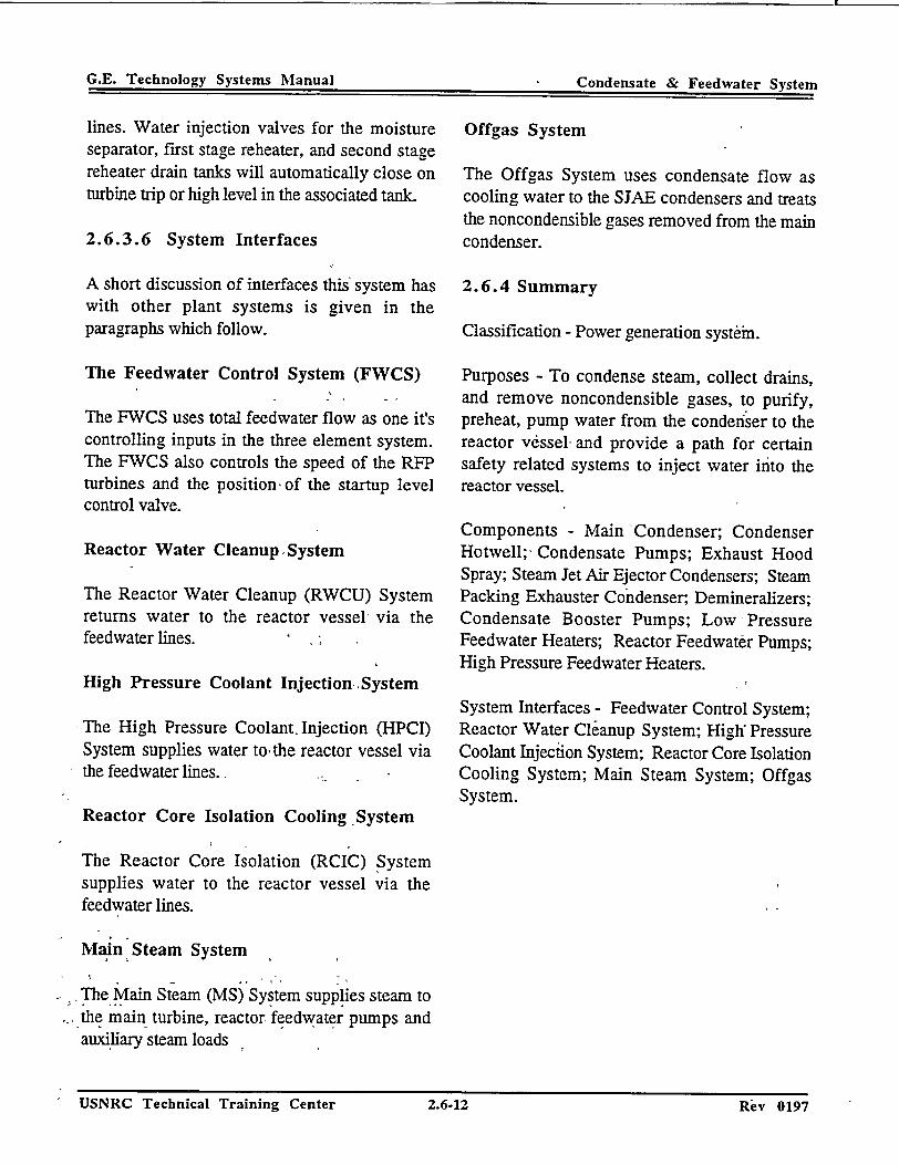
G.E TehnoogySysemsManalCondensate & Feedwater 43se
lines. Water injection valves for the moisture separator, first stage reheater, and second stage reheater drain tanks will automatically close on turbine trip or high level in the associated tank.
2.6.3.6 System Interfaces
A short discussion of interfaces this system has with other plant systems is given in the paragraphs which follow.
The Feedwater Control System (FWCS)
The FWCS uses total feedwater flow as one it's controlling inputs in the three element system. The FWCS also controls the speed of the RFP turbines and the position of the startup level control valve.
Reactor Water Cleanup, System
The Reactor Water Cleanup (RWCU) System returns water to the reactor vessel via the feedwater lines.
High Pressure Coolant Injection, System
-The High Pressure Coolant, Injection (HPCI) System supplies water to, the reactor vessel via the feedwater lines..
Reactor Core Isolation Cooling System
The Reactor Core Isolation (RCIC) System supplies water to the reactor vessel via the feedwater lines.
Main-Steam System
The Main Steam (MS) System supplies steam to - the main turbine, reactor feedwater pumps and
auxiliary steam loads
Offgas System
The Offgas System uses condensate flow as cooling water to the SJAE condensers and treats the noncondensible gases removed from the main condenser.
2.6.4 Summary
Classification - Power generation systein.
Purposes - To condense steam, collect drains, and remove noncondensible gases, to purify, preheat, pump water from the condenser to the reactor vessel, and provide a path for certain safety related systems to inject water into the reactor vessel.
Components- Main Condenser; Condenser Hotwell;, Condensate Pumps; Exhaust Hood Spray; Steam Jet Air Ejector Condensers; Steam Packing Exhauster Condenser; Demineralizers; Condensate Booster Pumps; Low* Pressure Feedwater Heaters; Reactor Feedwater Pumps; High Pressure Feedwater Heaters.
System Interfaces - Feedwater Control System; Reactor Water Cleanup System; High Pressure Coolant Injection System; Reactor Core Isolation Cooling System; Main Steam System; Offgas System.
USNRC Technical Training Center 2.6-12 Rev 0197
G.E. Technolog:y Systems Manual
USNRC Technical Training Center 2.6-12 Rev 0197

Drain Cooler
Makeup to Steam Seal Evaporator
Drain Cooler
To CST/CRO Pumps
To Loop Seals
To Valve. Seal Wtr
, Condenser
RFP Seal Wtr Return
10K Throuygh SS.onde•ner
Figure 2.6-1 Condensate System
I Pt
-L

Primary Containment "I Wat
FCV 10
Figure 2.6-2 Feedwater System
NiFrom
Condensate System
0
/D

TURBINE EXHAUST STEAM
EXPANSION JOINT
CIRCULATING WATER CONNECTIONS
HOT WELL STORAGE
FIGURE 2.6-3 CONDENSER FLOW PATHS
CONDENSER CROSSCONNECT PIPES
2.6-17

DRAINS INLET (FROM "C" HEATER)
AIR VENT
SAFETY VALVE
INLET
DRAIN FLOW
IMPINGEMENT PLATE
SUPPORT PLATES
DRAINS OUTLET (TO FLASH TANK)
FEEDWATER OUTLET
DRAINS OUTLET AIR VENT
WATER BOX DIVIDER PLATEDRAINS INLET
DRAIN COOLING SECTION
Figure 2.6-4 Typical Horizontal Feedwater Heater
STEAM INLET

AIR TAKE OFo:
TUBE SUPPORT PLATES
SAFETY VALVE
CONDENSATE LANE
I STEAM LANE
DRAINS INLET
IMPINGEMENT PLATE
LID. LEVEL CONTROL CONNECTION
GAGE GLASS
DRAIN COOLING SECTION
BAFFLES BAFFLS i •,.• STEAM INLET
TUBE SHEET
FEEDWATER
DRAINS OUTLET OUTLET
iFEEDWATER INLET
WATER BOX DIVIDER PLATE
Figure 2.6-5 Typical Vertical Feedwater Heater
2.6-21
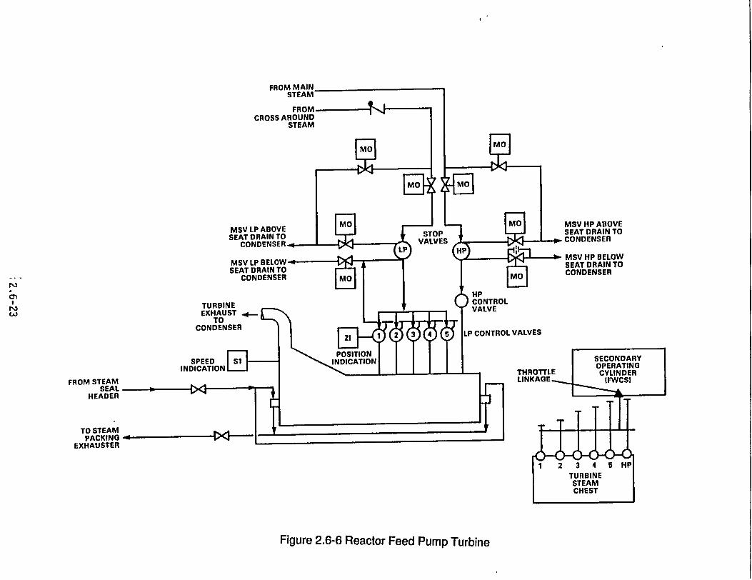
FROM STEAM SEAL
HEADER
TO STEAM PACKING
EXHAUSTER
Figure 2.6-6 Reactor Feed Pump Turbine

Figure 2.6-7 Reactor Feed Pump Oil System

E
U)
CI
E• E 2.- 0 LL 0 LL.
I
------ - -- - - -- -
I I I I I I I ! I I_
I.-
Drain Tank
I I I r-� I
L.....J�- J1stPt.Y�. -I �Htr.J
y Drin Tanak Moist. Sep.
rdP G
-------------------
Figure 2.6-8 Moisture Separator Reheater
2.6-27
Condenser Hotwell
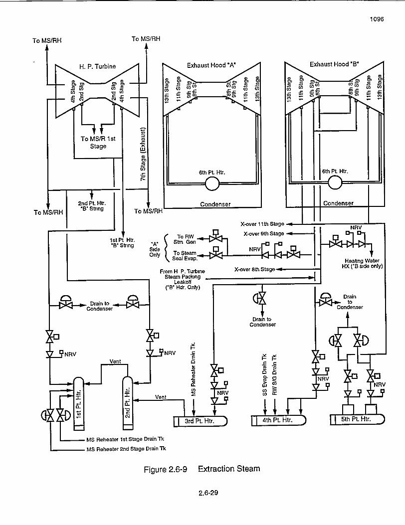
1096
To MS/RH
H. P. Turbine Exhaust Hood 'A'
6th P. Htr.
0
X-over 11 th
From H P. Turbine Steam Packing
Leakoff ("B" Hdr. Only)
I-
CD
a:
Exhaust Hood 'B"
COC
MS Reheater 1st Stage Drain Tk
MS Reheater 2nd Stage Drain Tk
Figure 2.6-9 Extraction Steam
2.6-29
'NRV

'A' Htr. Str. Only Moisture FirstStage Second Stage
6 Separator Reheater IReheater
Stm. Seal Evap. RW Stm. Gen.
6th pt. Htr. Moisture Sep. Tst Stage Rhtr. 2nd Stage Rhtr.
"i"1 •_ LV - 110 LCV - 09AH
-n LCV- 0110
(D
m LCV - 07AN
' ' I~i LO'V•AN (,3rd pt.'Htr. , ,_
S~LCV -03AH (4th pt. Htr,., •nCC
5"-- LCV - 01AN >
"rl3
0 - 07-A
-n
LC-08A

Boiling Water Reactor GE BWR/4 Technology
Technology Manual
Chapter 2.7
Reactor Core Isolation System
G.E. Technology Systems Manual Reactor Core Isolstion Cooling System
Table of Contents
2.7 REACTOR CORE ISOLATION COOLING SYSTEM ................................ ........ 1
2.7.1 Introduction ........................................................................................ 1
2.7.2 Component .................................................................................... 2
2.7.2.1 Steam Supply Isolation Valves ........................................................ 2
2.7.2.2 Steam Supply Shutoff Valve ........................................................... 2
2.7.2.3 Turbine Trip Throttle Valve ............................................................. 2
2.7.2.4 Turbine Governor Valve ................................................................. 2
2.7.2.5 RCIC Turbine ............................................................................. 2
2.7.2.6 RCIC Turbine Auxiliaries ............................................................. 2
2.7.2.7 RCIC Turbine Exhaust Path ............................................................. 3
2.7.2.8 RCIC Pump Suction Path ............................................................... 3
2.7.2.9 RCIC Pump .............................................................................. 4
2.7.2.10 RCIC Pump Discharge Path ............................................................ 4
2.7.2.11 RCIC Valve Controls ................................................................... 4
2.7.3 System Features and Interfaces ............................................................. 4
2.7.3.1 RCIC Flow Controller ................................................................... 4
2.7.3.2 RCIC Automatic Initiation .............................................................. 5
2.7.3.3 Test Features ............................................................................... 5
2.7.3.4 Automatic Isolation ...................................................................... 5
2.7.3.5 Automatic Turbine Trips ................................................................. 6
2.7.3.6 System Interfaces ........................................................................ 6
2.7.3.7 PRA Insights ............................................................................ 7
2.7.4 Summary ........................................................................................... 7
USNRC Technical Training Center 2.7-i - Rev 0797

G.E. Technology Systems Manual Reactor Core-Isolstion Cooling System
SList of Figures
2.7-1 Reactor Core Isolation Cooling System ........................................................... 9 2.7-2 RCIC Turbine Trip and Throttle Valve ......................................................... 11 2.7-3 Testable Check Valve ........................................................................... 13 2.7-4 RCIC Turbine Control Diagra ................................................................. 15
U�INKL lecunical Iraining Center 2.7-li Rev 0797tJINRC Iechnical Training Center 2.7-ii Rev 0797

G.E. Technology Systems Manual Reactor Core Isoistion - Coolin! System
2.7,, REACTOR CORE ISOLATION COOLING SYSTEM
Learning Objectives:
1., State.the system's purpose. 2. Explain how the system accomplishes its
purpose. 3. Place the following system components in
flow path order: a. -Suction valve b. RCIC pump, c.- Minimum flow valve d. Injection Valve
e., Air operated check valve 4. State the systems initiation, isolation, and
S-turbine trip signals.
5. Explain the systems response to an automatic initiation, isolation, and turbine trip.
6. Explain the interfaces this system has with the following systems or components: , a.- Main Steam System b. -Condensate and Feedwater System
-c. -Suppression Pool .d. -Condensate Storage Tank e. -Nuclear Steam Supply Shutoff System
2.7.1 Introduction
The purpose of the Reactor Core Isolation Cooling (RCIC) System are to provide makeup water to the reactor vessel for core cooling when the main steam lines are isolated or the Condensate and Feedwater System 'is not available..
The functional classification of the RCIC System is that of a safety related system. Its regulatory classification is an engineered safety feature (ESF) system.
The RCIC System (Figure 2.7-1) consists of a steam turbine driven pump and associated valves and piping capable of delivering water - to -the reactor vessel at operating •conditions. The turbine is driven by steam produced from decay heat and exhausts to the suppression pool.
The RCIC System is normally aligned to remove water from the condensate storage tank and pump the water at high pressure to, the reactor vessel via the 'A' feedwater line. The suppression pool is an alternate source of.water. Additional discharge flow paths are provided to allow recirculation to the condensate storage tank for system testing, a pump minimum flow line to the suppression pool for pump protection, and recirculation for lube oil -and barometric condenser cooling. .
Following a reactor scram from power operation, fission product decay continues to produce heat. If the reactor vessel is isolated from the main condenser, -pressure will increase to the point at which safety/relief valves will open to relieve steam pressure. If the Condensate and Feedwater System is not operating, reactor vessel water level decreases as decay heat continues to boil
,away. coolant. This is tlhe reason the RCIC System was installed. The RCICSystem initiates automatically on level 2 (-38") reactor vessel water -level and maintains sufficient, reactor coolant inventory to allow complete shutdown without compromise of the fuel -cladding integrity. The system may also be manually
,-started by the operator and is functionally backed -up by,'the High _,Pressure Coolant, Injection -(HPCI) System (Section 10.1). ,- I
,2.7.2 Component
The major components of the RCIC System are discussed in the paragraphs which follow :
USNRC Technical Training Center 2.7-1 Key U�IY�I2.7-1USNRC Technical Training Center
G.E. Technology Systems Manual Reactor Core Isolstion -Cooling System
Rev 0797
G.E. Technology Systems Manual Reactor Core Isoistion Coolina System
2.7.2.1 Steam Supply Isolation Valves
The steam supply to the RCIC turbine taps off the 'A' main steam line on the reactor side of the inboard main steam isolation valve. Two normally open motor operated valves provide inboard and outboard primary containment isolation upon receipt of an isolation signal (Section 2.7.3.4). The valves may also be remotely operated from the control room.
2.7.2.2 Steam Supply Shutoff Valve
The steam supply shutoff valve is used for normal steam isolation for the RCIC turbine in the standby condition. The valve- is, normally closed afid receives an open signal on RCIC automatic initiation. It may also be remotely operated from the control room.
2.7.2.3 Turbine Trip Throttle Valve
The turbine trip throttle valve, Figure 2.7-2, is located just upstream of the governing valve and provides for rapid turbine isolation under various conditions. This valve is'bpened by an electric motor and closed by spring force. To open the valve, starting from the electrically tripped position, the motor must be first run in the closing direction. Since the valve is" already shut, a travelihg nut moves up along the valve stem, compressing a spring, until the nut latches onto the trip mechanism. Operating the motor in the opening direction now lifts the valve stem since the traveling nut is prevented from moving
'd6wnward by the trip mechanism' latch. When the valve is tripped by an electrical signal a latch releases the traveling nut and the spring forces the traveling nut and valve stem "down to the closed position. A mechanical trip is used to protect the turbine from overspeeding.
The mechanical trip releases the same latch but is independent of- the electrical trip mechanism. Once tripped mechanically, the overspeed trip mechanism must be reset by manually latching the mechanism. This valve can be used to throttle steam flow to the RCIC turbine if the governor valve fails open.
2.7.2.4 Turbine Governor Valve
The governor valve is controlled by an electro hydraulic system. The valve is opened by spring force and closed by RCIC turbine governor control oil pressure. The speed of the turbine is controlled by varying the operating oil pressure which is opposing the spring force. The RCIC flow control circuit (Section 2.7.3.1) determines what the valve position should be.
2.7.2.5 RCIC Turbine
The RCIC turbine is designed to accelerate rapidly from a cold standby condition to full load conditions within 30 seconds. The RCIC turbine is a horizontally mounted radial re-entry, noncondensing turbine designed to operate with a steam supply pressure ranging from 150 psig to 1135 psig. The RCIC turbine operates with a 10 psig exhaust pressure; exhausting to the suppression pool under water.
2.7.2.6 RCIC Turbine Auxiliaries
The RCIC turbine auxiliaries consist of the RCIC oil system and the RCIC barometric condenser system. These systems are described briefly in the paragraphs that follow.
RCIC Oil System
A small gear pump is driven by the RCIC oil system worm gear. Oil is supplied to the turbine
USNRC Technical Training Center Rev 0797
G.E. * Technology Systems Manual'° Reactor Core Isolstion Cooling Svste'm
2.7-2

G.E. Technoloay Systems Manual Reactor Core Isoistion Cooling System
and pump bearings for lubrication and to the
-governorvalve for control. Oil pressure is a
,function of turbine speed; thus at low speeds
there may not be sufficient pressure to provide
adequate lubrication and prevent bearing damage. For this reason the governor valve limits
minimum turbine speed to approximately 1000 rpm. In the normal operating speed range, a
spring loaded pressure regulating valve recirculates excess oil to the pump suction to
limit oil pressure to approximately 15 psig.
RCIC Barometric Condenser System
The barometric condenser system is supplied
-with the turbine. The-system prevents leakage "from the turbine shaft seals and turbine exhaust
casing drain. The system includes a barometric condenser, vacuum pump, hotwell, and a
condensate pump. The system starts
simultaneously, with automatic startup of the
RCIC System, although it may be started manually.
Steam leakage from the turbine gland seals,
-turbine trip throttle and governor valve stems, and turbine exhaust drainage is collected -in the barometric condenser. The steam is condensed
by.spraying water suppliedthrough the lube oil cooler and a pressure regulator from the RCIC pump discharge.
Liquid from the spray and condensed steam is
collected in the hotwell and pumped by a 125
VDC powered condensate pump back to the
suction of the RCIC pump. The condensate pump cycles on high and low hotwell level
signals with an initiation or start signal present. When the RCIC System , is in standby, the
barometric condenser is continually drained to
clean radwaste (CRW) through two air operated valves in the condensate pump discharge line
which operate off of level in the hotwell. Noncondensibles are removed from the condenser by a 125VDC powered vacuum pump
discharging to the, suppression pool. If the vacuum is excessive, a valve in the vacuum
pump discharge line, controlled by condenser pressure, will open and direct noncondensibles back to the condenser.
2.7.2.7 RCIC TurbineExhaust Path
The RCIC turbine exhaust line routes steam from
the exhaust of the RCIC turbine to,.the
suppression pool below, water level. The exhaust line is normally kept free of water during shutdown; conditions by a drain system that
removes condensation to the barometric condenser. Vacuum breakers are installed betweenthe suppression pool free air volume and the exhaust line to prevent drawing
suppression pool water into the line via a vacuum
created by condensation of steam in the line
,following RCIC.operation. The exhaust line
may-be isolated by amanual, normally locked open, valve ,and check valve arrangement.
The exhaust line is protected from over pressure by a RCIC turbine trip on high exhaust pressure. The high exhaust pressure trip is backed up by a
,set of mechanical rupture diaphragms (nominal -rupture point is 150 psig) which will relieve
.-pressure to the RCIC-room. The rupture ,diaphragms are arranged in a manner such that
the inboard rupture diaphragm constantly sees
RCIC turbine exhaust pressure and the outboard rupture diaphragm only sees exhaust pressure if
the inboard one fails. The space between the
exhaust rupture diaphragms is provided with an
orifice leakoff to the RCIC room and a series of
pressure switches which will initiate a RCIC isolation.
..IDzx , un
"USNRC Technical Training Center 2.7-3
G.E. -Technology Systems Manual Reactor Core Isolstion Cooling System
SevC I.
G.E. Teclnology Systems Manual> Reactor Core Isoistion Cooling System
2.7.2'.8 RCIC Pump Suction Path
The system can take suction from the condensate storage tank (CST) or the suppression pool. Normal suction is from the CST on a line common with the HPCI System suction line. The HPCI / RCIC suction, line inside' the CST is located lower than all other system suction lines. This ensures a reserved volume of water in the CST exclusively for the HPcI and RCIC Systems.
The suppression pool suction is from a 16 inch pipe that includes a stainless steel, suction strainer. The strainer is located above the suppression pool bottom to minimize plugging.
The suction will swap from the CST to the suppregsion pool if the CST level becomes low.
2.7.2.9 RCIC Pump
The RCIC pump is a turbine dri,&en, horizontal, miulti-stage, centrifugal pump. It is-designed to deliver 425 gpm, of which 25 gpm is circulated through the turbine auxiliaries leaving 400 gpm available for discharge into the reactor vessel. This flow' rate is approximately equal to the boil off rate from the reactor 15 minutes after shutdown. The RCIC pump is designed for
"water in the temperature 'range from 40°F to 140°F. The minimum NPSH requirement is achieved by locating the pump lower than its source of water. '
2.7.2.10 RCIC Pump Discharge Path
The RCIC pump discharges through the system flow element, outboard and inboard discharge valves, the air operated check valve and into the 'A' feedwater line where the flow is distributed inside the reactor vessel by the feedwater
spargers. A pump minimum flow line to the suppression pool and a cooling line for turbine auxiliaries tap off just before the flow element. A full flow test line shared by the HPCI System) taps off just downstream of the outboard discharge valve.
The air operated check valve (Figure 2.7-3) is provided to prevent leakage from the feedwater line into the RCIC, System when the injection valves are open. A pneumatic actuator and solenoid enable the valve to be tested to ensure that it will operate properly under emergency conditions. The valve is tested when no differential pressure exists to prevent valve damage and minimize the size of the air actuator. The actuator is not capable of closing the check valve and does not interfere with its operation if RCIC is initiated.
2.7.2.11 RCIC Valve Controls
The major RCIC System valves respond to automatic inputs from the RCIC initiation, automatic isolation or turbine trip circuits. In addition they may be remotely operated from the control room or the emergency shutdown panel. Except for the inboard steam line isolation valve, power to the valve motors and control circuits is 125 VDC. The inboard steam line isolation valve, which is inside the drywell, uses 480 VAC power to operate the valve motor and 125 VDC control power.
2.7.3 System Features and Interfaces
A short discussion of the system features and interfaces this system has with other plant systems is given in the paragraphs which follow:
USNRC Technical Training Center 2.7-4 Rev 0797
I-
G.E. Tech~nology System-s Mainual" Reactor Core Isolstion Cooling Systemnv
USNRC Technical Training Center 2.7-4 Rey 0797

G.E. Technology Systems Manual Reactor Core Isoistion Cooling System
2.7.3.1 RCIC Flow Controller
The RCIC System utilizes a flow controller (Figure 2.7-4) to automatically or manually control system flow upon initiation. Selection of either automatic or manual mode is performed by the control room operator. In the automatic mode (normal position), the controller compares actual RCIC System flow (sensed by a flow element on the discharge of the pump) with the desired flow setpoint (adjusted by the operator at the controller). Any deviation between actual and desired flow is then converted into a I hydraulic signal -which positions the governor
-valve as required to balance the flow signals. In manual mode the operator has direct control of RCIC system flow. The operator simply adjusts a manual potentiometer, at the flow controller, to create a signal used for positioning the governor valve to obtain the desired flow.
2.7.3.2 RCIC Automatic Initiation
The RCIC System is automatically started if reactor vessel water level decreases to the level 2 setpoint (-38"). The initiation logic is arranged in a one-out-of-two twice configuration.
When the initiation signal is received, several actions occur automatically:
:1',1 The barometric condenser's vacuum-pump
- starts. -- I
2. The turbine steam supply shutoff valve will open.
3. The RCIC pumps minimum flow valve will open on low system flow and high pump pressure if the stop valve and steam supply shutoff valve are-open.
4. The RCIC inboard discharge valve will open and stay open untill the turbine trips or the steam supply shutoff valve closes.
5. When system flow is above the setpoint the minimum flow valve will close.
6. ,The barometric condenser's condensate -pump will start when hotwell level reaches -high level,
7. -The RCIC test valves will receive a close signal.
8. The outboard discharge valve receives an open signal even though it is normal open.
9. The CST suction valve receives an open signal and, if closed, will open if either
suppression pool suction valve is closed. 10. When the steam supply yalve is fully open,
the steam line drain valves to the main condenser and ,the condensate pump drain valves to CRW close.
As the turbine begins to roll, an attached lube oil pump builds up, oil pressure and the turbine flow control system begins to -throttle the turbine governor valve. As the turbine speed continues to increase pump flow and-discharge pressure increase until a flow of.400 gpm is achieved ( flow controller setting).
Once initiated, the RCIC System will remain in operation until manually secured or until an automatic isolation or turbine trip signal is received. At-any time, the operator, cant take control. This is normally done after reactor water level has been restored within prescribed limits.
2.7.3.3 Test Features
Pump operability and flow tests are done by manually starting the system and pumping back to the CST. When the pump is running, the correct flow is verified. The RCIC test valve can be throttled to adjust pressure.
- - ��KevU7Y7 ¾ USNRC Technical Training Center 2.7-5 - - - -
G.E. Technology Systems Manual Reactor Core Isolstion Cooling System
2.7--5 .. .. S. .. . . .. ... Rev 0797:USNRC Technical Training Center

G.E. Technology Systems Manual Reactor Core Isolstion Cooling System
2.7.3.4 Automatic Isolation
Because the steam supply line to' the RCIC turbine: is, part of the- nucleadr system process barrier, automatic isolation signals are employed to isolate-the RCIC Systeifi. By isolating the RCIC System upon detection of a leak, the release of radioactive material is m-inimized. The RCIC System will automatically isolate from any one of the following:
1. RCIC steam supply pressure low (57 psig). 2. RCIC steam line high differential pressure of
291" H20 with a 3 second time delay. 3. RCIC steam line space temperature high
(193OF). 4. High pressure between the turbine exhaust
rupture diaphragms (10 psig).' 5. Manual (only if the system has been
automatically initiated).
Once 'an isolation signal is generated, the following automatic actions occur:'
1. The inboard and outboard steam supply isolation valves close.
2. The RCIC turbine trips.
All the isolation signals must be manually reset.
2.7.3.5 Automatic Turbine Trips
NOTE: High reactor vessel water level (+56.5"). This closes the steam supply shutoff valve but not the trip throttle valve. This allows for an autoiiatic restart if the reactor level decreases to -38" again.
The RCIC turbine is automatically tripped (shutdown), by closing the turbine trip throttle valve, to protect the physical integrity of the RCIC System. If any of the following conditions
are detected, the RCIC turbine will automatically trip:
1. Turbine overspeed a. Electrical trip (110%) b. Mechanical trip (125%).
2. Pump suction pressure low (15" Hg vacuum) 3. Turbine exhaust pressure high (50 psig).' 4. Any isolation signal. 5. Manual.
In addition to closing the turbine trip throttle and injection valve, the minimum flow valve to the suppression pool also receives a close signal when the 'turbine trips. The mechanical overspeed trip must be manually reset at the turbine and the isolation trip will not clear until the isolation logic has been manually reset. All the other trip signals automatically reset. Once the trip logic has been reset, the operator must manually reset the turbine trip
2.7.3.6 System Interfaces
A short discussion of interfaces this system has with other plant' systems is given in the paragraphs which follow.
Condensate Storage Tank
The condensate storage tank (CST) is the normal suction source for the RCIC System. The CST can also be used for full flow testing of the RCIC System.
Main Steam System (Section 2.5)
The Main Steam, System provides the RCIC System with steam through a penetration from the 'A' main steam line.
USNRC Technical Training Center 2.7.6 Rev 0797
I-
'G.E..Teihnology Systems MVanual ... Reactor Core Isolstion Cooling Systemv v
USNRC Technical Training Center 2.7-6 Rev 0797

G.E. Technology Systems Manual Reactor Core Isoistion Cooling System
Condensate Feedwater System (Section 2.6)
The RCIC System uses the 'A' feedwater line to inject water into the reactor vessel. Additionally, condensate which forms in the steam supply piping collects in a drain pot and flows to the main condenser through a drain trap.
Suppression Pool
The suppression pool is the alternate source of water for the RCIC pump. It also condenses the RCIC turbine exhaust steam and the RCIC pump minimum flow water is routed to the suppression pool.
High Pressure Coolant Injection System (Section 10.1)
The HPCI System has a functional interface with the RCIC System in that it backs up the function of the RCIC System by supplying high quality high pressure makeup to the reactor under isolation conditions. Additionally, the RCIC and HPCI Systems share a suction line from the CST and a test line to the CST.
2.7.3.7 PRA Insights
The Reactor Core Isolation Cooling (RCIC) System is a major contributor to core damage frequency for several cut set sequences. The RCIC System is designed to provide makeup water to the reactor vessel to offset the loss of vessel inventory due to decay heat. The system utilizes a steam driven pump with only DC power needed as an external power source. Failure of the RCIC System to perform its intended function could lead to core uncover and therefore core damage.
2.7.4 Summary
Classification - Safety related system; engineered safety feature system. Purpose - The RCIC is to provide makeup water to the reactor vessel for core cooling when the main steam lines are isolated or the Condensate and Feedwater System is not available.
Components - Steam supply isolation valves; steam supply shutoff valve; turbine governor valve; turbine; turbine auxiliaries; turbine exhaust path; pump suction path; pump; pump discharge path; valve controls.
System Interfaces - Condensate Storage Tank; Main Steam System; Condensate and Feedwater System; Primary Containment System; High Pressure Coolant Injection System.
.----- nan.,
USNRC Technical Training Center 2.7-7 nev ui�i2.7-7
G.E. Technology Systems Manual Reactor Core Isolstion Cooling System
R•ev 0177lUSNRC Technical Training Center
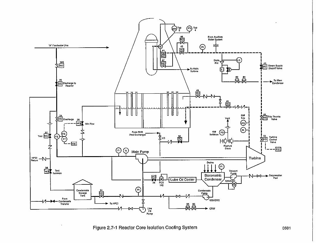
Typ 4
48 From Auxiliary Boller System
"A Feedwater Line E 42
Drain LS
AP IMOSteam Supply To Main T,_ Shutolf Valve Turbine 1
82 8l 35 • To Main
MO Discharge to -PoCondenser •,-J Reactor
49
5444 34 5 Trip Throttle
MO Discharge 3Vt Trip Valve
From RHR FS Heat E•changer I HTI51
5 T rbiTne FE FT LO MO cntt JH ý 1 1 1Valve
Drains
Test P Vacuum Barometric I Suppression
Lube Oil Cooler Condenser 125VDPo
nCondensate 31 Cnest Storage 0 9
Frm Tank 1•ýýJ5VD From
Condensate I25VDC Transfer To HPCI 95 83
Line I CRW
Figure 2.7-1 Reactor Core Isolation Cooling System 0601

LIMITORQUE OPERATOR
DC MOTOR
CLOSING SPRING
TRAVELING NUT
TRIP LATCH
POSITION INDICATING LIMIT SWITCHES
STEAM INLET
ELECTRICAL TRIP SOLENOID
OVERSPEED TRIP LOCKOUT LIMIT SWITCH
MANUAL TRIPPING DEVICE
TO TURBINE
TURBINE TRIP AND THROTTLE VALVE MECHANICAL OVERSPEED TRIP DEVICE
FIGURE 2.7-2 RCIC TURBINE TRIP AND THROTTLE VALVE
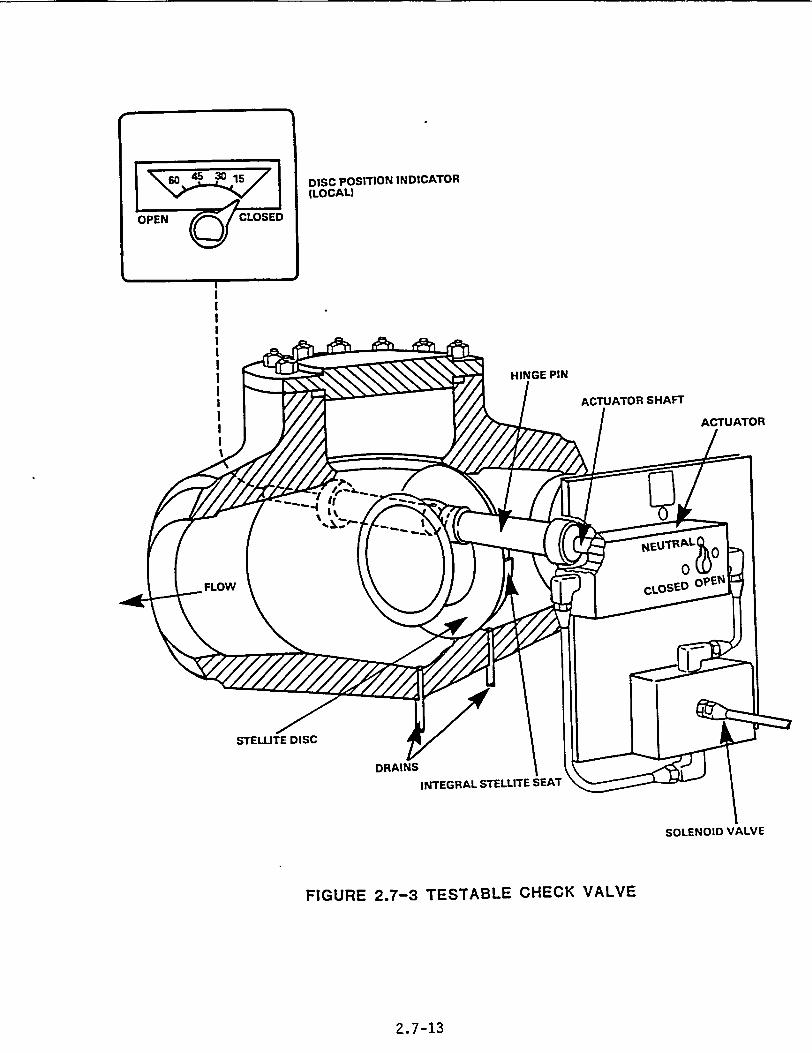
DISC POSITION INDICATOR (LOCAL)
SOLENOID VALVE
FIGURE 2.7-3 TESTABLE CHECK VALVE
2.7-13
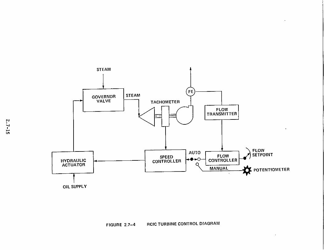
FLOW SETPOINT
POTENTIOMETER
OIL SUPPLY
FIGURE 2.7-4 RCIC TURBINE CONTROL DIAGRAM
Boiling Water Reactor GE BWR/4 Technology
Technology Manual
Chapter 2.8
Reactor Water Cleanup System

G.E. Technology Systems Manual Reactor Water Cleanup System
Table of Contents
2.8 REACTOR WATER CLEANUP SYSTEM
2.8.1 Introduction
2.8.2 Component Description
2.8.2.1 RWCU Inlet Piping
2.8.2.2 RWCU Pumps
2.8.2.3 Regenerative Heat Exchangers
2.8.2.4 Nonregenerative Heat Exchangers
2.8.2.5 Filter Demineralizer Units
2.8.2.6 RWCU Outlet Piping
2.8.2.7 System Bypass Valve
2.8.3 System Features and Interfaces
2.8.3.2 System Operation
2.8.3.3 Filter Demineralizer Operations 2.8.3.4 System Isolation
2.8.3.5 Component Trips and Interlocks
2.8.3.6 System Interfaces
2.8.4 Summary
2.8-1
2.8-2
List of Figures
Reactor Water Clean Up System
RWCU Filter/Demineralizer
USNRC Technical Training Center 2.8-i Rev 0191
1 1
1
1
1
2 2
2
3
3
3
3
4
5
5
5
6
7 9
G.E. Technology Systems Manual Reactor Water Cleanup System
Rev 0197USNRC Technical Training Center 2.8-i

G.E. Technology Systems Manual Reactor WateiK Cleanup System
* 2.8 REACTOR WATER CLEANUP, SYSTEM
Learning Objectives:
-1. State the system's purpose. 2. Explain how the system accomplishes it's
purpose. 3. State why reactor water purity is maintained
and how it is monitored. 4. Discuss, the system's isolation and trip' • -signals.
,-5. Explain the interfaces this system has with !:the following systems or components: a. reactor recirculation system b. reactor vessel system c. condensate and feedwater system d.-. reactor building closed loop cooling water
system
2.8.1 Introduction
The purposes of the Reactor Water Cleanup (RWCU) System are to maintain reactor water quality by filtration ,and ion exchange, provide a path for removal of reactor coolant from the vessel and aid water circulation in the reactor vessel bottom head region to minimize thermal, stratification. The reactor water quality is maintained to minimize corrosion, to minimize-, irradiation of corrosion products and subsequent; radiation problems, and to prevent fouling of heat
* transfer surfaces.
and discharge into a-common discharge header. The common discharge header in turn routes the -water through three' regenerative and two nonregenerative heat exchangers: From the nonregenerative heat exchangers, the water is
"-directed to the filter demineralizefs. Sample line penetrations are provided on both'sides of the filter demineralizers to ensure efficient system operation and the status of the reactor water quality.The outlet of the filter demineralizers can "be directed to the main condenser, the liquid radwaste system, and/or to the reactor vessel via the regenerative heat exchangers and both feedwater lines.' ,
2.8.2 Component Description
The major components of the RWCU system are discussed in the paragraphs whichl follow" and can be seen in Figure 2.8-1.
2.8.2.1 RWCU Inlet Piping
The major flow of the RWCU system is taken from the. suction .of the 'A', and 'B' reactor recirculation, pumps. An additional source of wateris provided'by a-line from the reactor vessel bottom head drain. Water is removed from the bottom head to minimize thermal stratification and-remove deposits from the bottom head region. A-temperature element is provided to give bottom head drain temperature indication.
Motor operated isolation valves are provided in The functional classification of the RWCU, -the RWCU supply lines, both inside and outside System is that of a power generation system. of the primary containment for isolating the
system during unsafe conditions.SThe RWCU System is a filtration 'and-'ion
exchange system used to maintain and monitor reactor vessel water quality. The RWCU pumps remove ,water from one of the recirculation system loops and the reactor vessel bottom head
2.8.2.2 RWCU Pumps
The RWCU pumps provide the needed motive force to overcome piping and equipment flow
USNRC Technical Training Center 2.8-1 * Rev 01972.8-1
G.E. Technology Systems Manual I Reactor WateIf•Cleanup System
",Rev 0197USNRC Technical Training Center

aReactor Water Cleanun Svsten
induced pressure losses and return the treated water back to the reactor vessel via the feedwater system. The RWCU pumps, are motor driven, horizontally mounted, centrifugal pumps with an externally supplied mechanical seal. One pump provides 100% system flow which corresponds to approximately 1% of rated feedwater flow.
Each pump is powered by a 50 HP motor which is supplied from a 480 VAC shutdown, board. The design pump flow rate is 207 gpm at 545°F with a developed head of approximately 565 ft. Pump bearing and seal cooling is provided by the Reactor Building Closed Loop Cooling Water (RBCLCW) System (Section 11.1). Control rod drive system water (Section 2.3) is used to flush the pump casing after maintenance.
2.8.2.3 Regenerative Heat Exchanges
The three regenerative heat exchangers are provided to recover sensible heat in the reactor vessel water and to reduce the cycle heat loss while also limiting the heat -load on the nonregenerative heat exchangers. The regenerative heat exchangers are tube and shell type heat exchangers with system influent water flowing through the tubes and' system effluent water flowing around the tubes., The influent water is cooled from approximately 530TF to 230°F while heating the effluent water from approximately 120'F to 430'F., Thus the processed cleanup water regains about 80 % of the total heat lost. This results in less thermal stress as the effluent water enters the feedwater system.
2.8.2.4 Nonregenerative Heat Exchangers
The nonregenerative heat exchangers provide the final reduction of water temperature prior to
entering the filter demineralizers. The nonregenerative heat exchangers are tube and shell type heat exchangers with RWCU water on the tube side and RBCLCW on the shell -side. Unlike the regenerative heat exchangers, the heat removed from the RWCU water is lost to another system.
2.8.2.5 Filter Demineralizer Units
The RWCU' filter demineralizer (F/D) units are provided to remove soluble and insoluble impurities from the reactor water. This process is accomplished by forcing the, F/D influent water through finely ground ion exchange resins.
The two filter demineralizer units are of a pressure precoat type in which the vessel filter tubes are coated with a filter aid and powdered ion exchange resin. These materials serve as the filter media and/or ion exchange agent and are held on to the screen type tubes by the differential pressure generated by the water flowing through each unit. Flow through the system is automatically controlled by flow control valves located at the outlet of each filter/demineralizer.
Each unit is composed of a pressure vessel which contains the filter tubes, a holding pump, instrumentation, controls, valves, and piping. Air operated inlet and outlet isolation valves and the flow control valve are furnished for each filter demineralizer unit to permit individual operation and servicing. Auxiliary components required for precoating, backwashing, and disposal of the resin are shared by both filter demineralizers.
The holding pump for each filter demineralizer holds the resin on the filter tubes by recycling flow through the units during standby periods, and is interlocked to start automatically when flow through a filter demineralizer falls below 75
USNRC Technical Training Center 2.8-2 Rev 0197USNRC Technical Training Center
G.E. Technology Systems Manual
2.8-2 Rev 0197

G.. ehn g. Syt.sMnul.ectrWaer ..au System ....
gpm. If flow is shut off or lost through a filtei demineralizer, the precoat will fall off the filter
,-tubes. When, flow is lost through a filtei -. demineralizer that unit must be backwashed and
,precoated before being placed back into service. A strainer is also after each F/D unit to minimize the material that could enter the reactor vessel in the event of a filter precoat failure.
A bypass line, controlled using a motor operated valve, is provided for bypassing flow around the ,filter demineralizers.
2.8.2.6 RWCU Outlet Piping
During normal system operation, flow is routed through the shell- side of the regenerative heat exchanger, through the motor-operated isolation valve and In to the feedwater lines.The RWCU
-flow returning to the 'A' feedwater line first enters the reactor core isolation cooling system
- piping which connects to the 'A' feedwater line. The RWCU, returning to the 'B' feedwater line
,,first enters the high pressure coolant injection piping which connects to the 'B' feedwater line. . )During other operations involving reactor vessel blowdown operations, flow can be routed to the main condenser or to the liquid radwaste system. Blowdown flow is directed through a common .header .which is controlled by a flow, control -valve and a restricting orifice. Effluent from the blowdown flow control valve is then directed to the -main condenser- or liquid radwaste via appropriate motor operated valve. The drain line to the liquid radwaste system is provided with a
- pressure relief valve (setpoint 150 psig) to protect the low pressure piping from overpressurization. "The relief valve relieves to the main condenser via the RWCU blowdown piping
C I .
- 2.8.2.7 System BypassValve
A bypass line containing a normally closed isolation valve (MOV-35) connects the RWCU
-pump -discharge line with the 'feedwater return line. This line bypassesthe heat exchangers and
* filter demineralizers -and is' used primairily to prevent reactor vessel temperature stratification.
2.8.3 System Features and Interfaces
A short -discussion of system features and interfaces this -system has with- other plant "systems is given in. the paragraphs. which follow.
2.8.3;1 System Monitoring
The principal parameters monitored are shown in Figure 2.8-1. They include system temperatures, system pressures, demineralizer differential pressure, conductivity, and system flows.
2.8.3.2 System Operation
.,The RWCU System maintains the reactor water effluent conductivity -at less than 0.1 -micro
• mho/cm and undissolved solids at less than 0.01 °:ppm.,
:-The system is'normally operated continuously ,during all phases of reactor plant operation, startup, shutdown, ,and refueling. Blowdown
,(draining) .is normally used only to remove -excess or impure water from the reactor pressure vessel at low steaming rates or' when the reactor is shutdown.
,The reactor water quality depends on several
-factors which include: corrosion of primary system- materials; input of impurities and corrosion products via the feedwater piping;
USNRC Technical Training Center 2.8-3 Rev 0197SRev 0197
G.E. Technology Systems Manual -. : Reactor Water Clea'nun System-
.... USNRC Technical Training Center 2.8-3

, G.E. Technology Systems Manual
radioactive decay; and removal of impurities by the filter/demineralizers.
Impurities in the reactor water are of two forms, soluble and insoluble. By definition; insoluble material is that collectible on a type HA millipore filter paper; the remainder is soluble. The soluble materials are suspended in. the water until collected or plated onto some surface.
The insoluble materials are removed by filtration. Corrosion product, inputs from the primary systems have been minimized by use of stainless steel vessels, pipes, and heat exchangers. The majority of corrosion product input originates in the condenser and feedwater components where carbon steel piping and components are used. Cleanup system operation is necessary to maintain reactor water purity. Reactor operation without the cleanup system is limited to relatively short periods of time.
Normal Operation
During normal operation, 200 gpm of reactor vessel water flows through the RWCU System. Of this total flow rate, approximately 180 gpm is taken-from the recirculation system lines to decrease the amount of impurities before flow enters the core area. The remaining 20 gpm is taken from the reactor vessel bottom head region which tends to be the largest collection point for solids in the reactor since It is the low point of ,the vessel, and flow in this region is restricted by, bottom head internal components (CRD housings and incore detector housings). At this flow rate, one RWCU System pump and both filter demineralizer units are required to be operating. This flow rate is determined to be sufficient to maintain, sufficient reactor vessel water quality by, continually removing the impurities before a large buildup occurs in the
Riacor. ~f- -1
reactor vessel as a result of concentration. The reactor water quality is maintained to: (1) minimize the corrosion of materials used in the plant; (2), minimize the levels of radioactive nuclides in the coolant; and (3) prevent fouling of heat transfer surfaces.
Blowdown
During a plant startup, shutdown, or low steaming rates, it is necessary for the operator to drain water from the vessel in order to mairitain a proper vessel level. This is done with the blowdowin portion of the RWCU System. Water, from the outlet of the filter demineralizers, can be rejected to'the main condenser or to ihe liquid radwaste systerm rather-than being returned to the vessel. In this way water is removed from the reactor. The blowdown flow rate is controlled manually- from' the control room via a manually operated controller. The appropriate motor operated valve is opened to direct flow to either the main condenser or radwaste. Foll6wing blowdown alignment, the blowdov~n control valve is adjusted to drain the desired amount of water from the reactor vessel. The main condenser is the preferred blowdown point in order to limit the duty on the liquid' waste processing ficilities. During the blowdown operation, the greatest duty is imp6sed on the nonregenerative heat exchangers because much of the return flow that was going to the regenerative' heat exchangers is now' bypassing them. During the blowndown operation, the water! temperature limit before the filter demineralizers is'<130*F and the reactor building closed'cooling, water from the nonregentive heat exchanger is limited to <180*F. If, during blowdown operation, high pressure is sensed downstream of the blowdown control valve or if low pressure is sensed upstream, the blowdown control valve is automatically closed. The high
YTC�TY)r ''.L� .. ' . . -zecnnIc3I iraining LenterRev 0197
l
USN11Cg i echnical I raining C~enter 2.8-4

G.E. Technology. Systems Manual Reactor Water Cleanup System
-pressure sensor protects the piping downstream of the control valve, and the low pressure sensor prevents draining the entire RWCU system, piping via a siphon effect to the main condenser or radwaste. Blowdown to the main condenser is
.not allowed if the condensate demineralizers are not in operation, the RWCU filter demineralizer effluent conductivity is > 0.1 [.mho, or the activity of the water is greater than the minimum detectable activity when the filter demineralizers are bypassed.
2.8.3.3 Filter Demineralizer Operations
Two filter demineralizer operations are discussed in the paragraphs which follow.
Backwashing,
,When the differential pressure across a filter demineralizer unit approaches 20 psid, the outlet conductivity reaches 0.1 micro-mhos, or the outlet to inlet conductivity approaches 1.0, the filter demineralizer is removed from service for backwashing and precoating.
Backwashing consists of removing the spent -resins from the. filter demineralizer'holding elements. This is accomplished by the use of an: air blast injected into the filter demineralizer to dislodge the precoat. Condensate is then pumped into the filter demineralizer through the outlet line. The drain'line is then, opened, and the -mixture of water and spent resins is pumped to the cleanup phase separator tank of the radwaste facilities.
Precoating
After the filter demineralizer is backwashed, it is now ready for a new application of resins. The filter demineralizer is precoated by circulating a
slurry of the resin from the resin feed tank onto the stainless steel resin holding elements. The slurry deposits evenly on the elements while the water returns to the resin feed tank. Precoat recirculation continues until the return water is clear. At this time, a holding pump is automatically started to maintain the precoat in place on the holding elements. The filter demineralizer is then returned to service, and the holding pump -flow stops as system flow increases.
2.8.3.4 System Isolation
The RWCU'System supply isolation valves will automatically close on any of the following signals. " Auto closure signals for inboard Isolation valve (MOV-33)
a. RWCU heat exchanger/pump area high temperature (1551F)
b. Reactor vessel low level (-38") c. RWCU system high differential flow (44
gallons for >45 seconds) r -;
d. Main steam tunnel penetration' area temperature high (175"F)
-Auto closure signals for outboard isolation valve -,'(MOV-34) are the same as for MOV-33 plus the
either of the following two signals:
a. . Standby liquid control system actuation b. Non-regenerative heat exchanger high outlet
temperature (1400F)
'2.8.3.5 Component Trips and Interlocks '
The RWCU system contains numerous trips and interlocks to protect system components from damage.
USNRC Technical Training Center 2.8-5 Key UJYI
G.E. Technology, Systems Manual ý Reactor Water 'Cleanup System
R~ev 01972.8-5ýUSNRC Technical Training Center

G.E.Tecnoloy Sstem MaualReactor Water Cleanup System
2.8.3.6 System Interfaces"
A short discussion of Interfaces this system has with other plant systems is given in the paragraphs which follow.
Reactor Building, Closed Loop Cooling Water System (Section 11.1)
The reactor building closed loop cooling water system provides cooling water to the RWCU System pumps and the nonregenerative heat exchangers.
Recirculation System (Section 2.4)
The 'A' and 'B' recirculation system loops supply water to the RWCU System.
Reactor Vessel System (Section 2.1)
The reactor vessel provides water to the RWCU System via the bottom head drain line.
Condensate and Feedwater System (Section 2.6)
The condensate and feedwater system provides a return path to the vessel for the processed water. The main condenser can be used to collect water from RWCU System blowdown.
Liquid and Solid Radwaste Systems (Sections 8.2 and 8.3)
The radwaste facilities are used to collect water from RWCU blowdown and spent resins from the filter demineralizers.
Nuclear Steam Supply Shutoff System (Section 4.4)
The nuclear steam supply shutoff system provides automatic closure signals to the various isolation valves of the RWCU System upon sensing certain conditions.
Standby Liquid Control System (Section 7.4)
The standby liquid control system provides an isolation signal-to the RWCU system upon system initiation.
2.8.4 Summary
Classification : Power generation system
Purposes : To maintain reactor water quality by filtration and ion exchange, provide a path for removal of reactor coolant from the vessel and aid circulation in the reactor vessel bottom head to minimize stratification.
Components: Inlet piping, pumps, regenerative heat exchangers, nonregenerative heat exchangers, filter demineralizer units, outlet piping.
System Interfaces: reactor building closed loop cooling water system; recirculation system; reactor vessel system; condensate and feedwater system; liquid and solid radwaste systems; nuclear steam supply shutoff system.
U�iNKL. leclinical training Center Rev 0197Rev 0197
G.E. Technology Systems Manuali
USI'•RC Technical Training Center 2.8-6

00
L - - - - - - - - - - - - - -
Fiaure 2.8-1 Reactor Water Cleanup Systemo Co

TO REGEN. HEAT EXCHANGERS
FROM NONREGEN.
HEAT EXCHANGERS
FIGURE 2.8-2 RWCU FILTERIDEMINERALIZER

Boiling Water Reactor GE BWR/4 Technology
Technology Manual
Chapter 3.0
Process Instrumentation and Control Systems

Table of Contents
3.0 PROCESS INSTRUMENTATION AND CONTROL SYSTEMS ................................... 1
3.0.1 Reactor Vessel Instrumentation System (Section 3.1) ......................................... 1
3.0.2 Electro Hydraulic Control System (Section 3.2) ............................................... 1
3.0.3 Feedwater Control System (Section 3.3) ..................................................... 1 3.0.4 Composite BWR Control Systems ............................................................... 1
List of Figures 3.0-1 Process Instrumentation and Control Systems ................................................... 3 3.0-2 BWR Control Systems ............................................................................... 5
USNRC Technical Training Center 34J-i Key utyo3.0-i
G.E. Technology Systems Manual Process Instrumentation & Control
Rev 0151oUSNRC Technical Training Center
G.E. Technolo2v Systems Manual Process Instrumentation & Control
3.0 PROCESS INSTRUMENTATION AND CONTROL SYSTEMS
The systems discussed in this chapter are those that have to do with process instrumentation or process control. The control systems used to alter reactor core reactivity are discussed in Chapter 7. The process instrumentation and control systems are shown in Figure 3.0-1 and include the following systems: the Reactor Vessel Instrumentation System, the Elecfro Hydraulic Control System, and the Feedwater Control System.
3.0.1 Reactor Vessel Instrumentation System (Section 3.1)
The Reactor Vessel Instrumentation System provides information concerning reactor vessel water level, reactor vessel pressure, reactor vessel temperature, and core flow rate. This information is used for control and automatic trip functions.
3.0.2 Electro Hydraulic Control System (Section 3.2)
The Electro Hydraulic Control System maintains a constant reactor pressure for a given reactor power level; controls the speed and load on the turbine generator, and provides protection for the main turbine.
3.0.3 Feedwater Control System (Section 3.3)
The Feedwater Control System regulates the flow of feedwater to the reactor vessel in order to maintain reactor water level. The Feedwater Control System measures and uses total steam flow, total feedwater flow, and reactor vessel water level signals to carry out its function.
3.0.4 Composite BWR Control Systems
Figure 3.0-2 shows a composite drawing of BWR control systems. In addition to the Electro Hydraulic Control System and Feedwater Control System, which are discussed in this chapter, some Chapter 7 reactivity control systems are also shown to assist in understanding overall plant response. The three Chapter 7 systems included in the drawing are the Reactor Manual Control System, the Recirculation Flow Control System, and the Reactor Protection System.
.�--- nine
USNRC Technical Training Center 3AJ-1 x�ev ulyliUSNRC Technical Training Center 3.0-1
G.E. Technology Systems Manual Process Instrumentation & Control
Rev 0176

,Steam Flow Control (EHC) System u"" Signal
I P
" J .l i"- - - -• I-r Stop
VesselI MSIV's I .Valves Pressure• x Bypa ss Signals Feed Flow Bypass_ [ Control •~Signal Valves AL." - Valves
Vessel Level L..T.I-I
Signals rbIne Generator
I I
FIos ICondensate Vesl•I FedHatrI Cored eate
SignalHihPesr IedHaes..
I F t o Cr Ium
S.gmnal Recirculation
Pump Pum
Vessel p LwPesr
Temperature---lk1 TE RecorFe Signal u
Vessel Level Fedae~nto
Total Steam Flow SyFeswtemrFControO
Total Feed Flow
Finiirpn nf-i Process instru~mentation & Control SytmsC

Control Rod 1 Drives
r -Ij I~~
Reactor Reactor Manual P System Control System LiP J L(RMCS) [7. . I
Electro Hydraulic Control (EHC) System
3.2
MA P Ir - - - - - - - - - - - - - - - - - - - - - T- - - r
I MSIV's H Stop I LL Valves
jI I
Bypass I HCL. _l_ H Control Vlaves Valves
tT:urbine Generator
S- Condenser &Hotwell
Recirculatlon _ um Condensate
._....J Codensateate
ener-neraFuzerd
o Cul MCondensate I Boster Pump Boost r .Pum Low Pressure
3o= Reactor Feed
SJ ~~~Feed Heaters RatrFe
SHigh Pressure u
Feed Heaters
Recirculation Flow Control .KA-, - -
System (RFCS)
Figure 3.0-2 BWR Control Systems(0
m ill II

Boiling Water Reactor GE BWR/4 Technology
Technology Manual
Chapter 3.1
Reactor Vessel Instrumentation System

G.E. Technology Systems Manual Reactor Vessel -Instrumentation .System
Table of Contents 3.1 REACTOR VESSEL INSTRUMENTATION SYSTEM ......................................... 1
3.1.1 Introduction .................................................................................... 1
3.1.2 Component Description ......................................... I
3.1.2.1 Reactor Vessel Water Level Instrumentation ..................................... 1
3.1.2.2 Reactor Vessel Pressure................... ........................ 2
3.1.2.3 Reactor Vessel Temperature..................................3 3.1.2.4 Reactor Core Flowrate and Differential Pressure ................................ 3
3.1.2.5 Vessel Flange Seal Leak Detection ................................................ 4
3.1.3 System Features and Interfaces ............................................................ 4
3.1.3.1 Reactor Vessel Level Ranges ..................................................... 4
3.1.3.2 Reactor Vessel Level Functions .................................................... 5
3.1.3.3 Reactor Vessel Pressure Ranges ................................................. 6
3.1.3.4 Reactor Vessel PressTFmnction ................................................... 7
3.1.3.5 Trip Signal Devices ................................................................. 7
3.1.3.6 Reactor Core Flowrate With One Recirculation Pump In Service ............. 8
3.1.3.7 Jet Pump Flow Effect on Level Indication ........................................ 8
3.1.3.8 System Interfaces .................................................................... 8
3.1.4 BWR Differences ............................................................................ 9
3.1.5 PRA Insights ................................................................................. 9
3.1.6 Sum m ary ......................................................................................... 9
List of Tables 3.1-1 Summary of Vessel Level Trips .............................................................. 11
3.1-2 Summary of Reactor Pressure Trips ........................................................... 13
3.1-3 Narrow Range Level Interlocks ................................................................. 15
3.1-4 Wide Range Level Interlocks .................................................................. 17
3.1-5 Reactor Pressure Interlocks .................................................................. 19
USNRC Technical Training Center 3.1-i Rev UIYIUSNRC Technical Training Center Rev,_0151S• 3 .1-i
G.E. Technology Systems-Manual Reactor Vessel Instrumentation Sqv~tpm
List of Figures 3.1-1 Vessel Level Instrument Ranges ............................................................... 21 3.1-2 Reactor Vessel Level and Pressure Instrumentation ....................................... 23 3.1-3 Vessel Temperature Monitoring .............................................................. 25 3.1-4 Jet Pump and Core D/P Instrumentation ...................................................... 27 3.1-5 Core Flow Summing Network ............................................................... 29 3.1-6 Flange Seal Leak Detection' .................................................................... 31 3.1-7 Analog Transmitter Trip Unit System Block Diagram ...................................... 33
USNRC Technical Training Center 3.1-u Rev 0197
I -__________
Rev 0197
Reactor Vessel Instrumentation Svstem
USNRC Technical Training Center 3.1-ii

G.E. Technology Systems Manual Reactor Vessel Instrumentation System 3.1. REACTOR VESSEL INSTRU-
.,3.1. REACTOR, VESSEL INSTRUMENTATION SYSTEM
Lesson'- Objectives:
1. State the system's purposes. 2. Describe the ranges of reactor vessel water
level instrumentation and the uses for each range:
-.3. State the other monitored parameters. 4. State the reason for each signal listed in tables
3.1-1 and 3.1-2.''
S-:3.1.1 Introduction
The purpose of the Reactor Vessel Instrumentation System is to .provide sufficient information concerning reactor vessel water level, reactor, vessel pressure, reactor vessel temperature,' core flow rate, and core differential pressure to allow safe plant operation and provide initiation signals for safety systems.
The functional classification of the Reactor Vessel Instrumentation System is that of a safety related system,' although some portions are strictly forpower generation. ,
The Reactor-Vessel Instrumentation, System consists 'of several individual subsystems that
. monitor the following reactor parameters:
vessel water level - vessel pressure - vessel temperature - core flow rate and differential pressure - vessel flange seal leak detection
Reactor vessel water level, is measured in the vessel downcomer ,annulus and displayed on five different ranges. Level is a controlling input for the Feedwater Control System (FWCS), and
pr6vides -protective signals to the Reactor Core Isolation Cooling (RCIC) System, the Reactor Protection '(RPS) System; the Nuclear Steam Supply Shutoff (NSSSS) System, :Recirculation Flow Control (RFC) System, and Emergency Core Cooling (ECCS) System:.
Reactor vessel pressure is measured in the Vessel steam space and displayed on narrow and wide range pressure indicators. Pressure ý provides protective signals to the RPS," RFC, System' and
"ECCS.
Reactor Vessel shell temperature is measured by "thermocouples and displayed, for monitoring thermal'stress on the vessel:
The plant power output capability is proportional to the ability to' remove the heat generated, so accurate core coolant flow measurements are required to evaluate core thermal behavior.' Since the total flow that passes through the core must also pass , through the jet pumps,, the'flow through each jet pump is measured and summed to yield total core flow.
Degradation of the inner seal on the vessel flange to head flange ,seal surface is measured by a flange seal leakage detection --system.
'-3.1.2 Component Description.
'The major components 'of each Reactor Vessel Instrumentation Subsystem are discussed in the paragraphs whichfollow. "
3.1.2.1 Reactor. Vessel Water Level' J:- -Instrumentation
-During normal reactor operation, reactor water level is maintained approximately 17 feet above the top of the active fuel (Figure'3.1-1).
USNRC Technical Training Center 3.1-1 KeY IJiYIRev 0197
G.E. Technology -Systems Manual Reactor _Vessel Instruinentation System
, -, USNRC Technical Training Center 3.1-1
G.E........ .....Sstems M lReactor Vesel In• trumentat•on 3 +
Maintaining an acceptable water level in the reactor vessel ensures that a sufficient quantity of reactor coolant is available to dissipate the heat generated by the core and the reactor is operating within the initial conditions assumed for the various analyzed accidents.
To aid the operator in safely operating the plant, the reactor vessel water level is one of the reactor vessel parameters measured and displayed. The measured water level is the level existing in the reactor downcomer annulus. To measure this water level, two connections are made to the reactor vessel and connected to a differential pressure transmitter. One connection penetrates the reactor vessel in the steam volume area. This high pressure side penetration connects to a condensing chamber which is, an enlarged volume in the piping. -This chamber is not thermally insulated and remains at approximately the same temperature as the surrounding drywell atmosphere. Steam. entering the condensing chamber condenses on the inside of the chamber. The resulting condensation collects in a reference leg which connects to one side of a level transmitter.
The lower penetration (variable leg) enters the reactor vessel in the downcomer annulus region. This line connects to the low pressure side of the level transmitter. With this arrangement, reactor pressure is felt on both sides of the differential pressure detector and does not affect the measure"ment. The pressure'caused by the reference column of water is compared to the pressure resulting from the water level inside the reactor vessel: Since the reference leg remains constant, because of the action of the condensing chamber, any change in the height of the reactor vessel .water level produces a difference in the water column pressures that is proportional to the reactor vessel water level.
The level transmitter converts this differential pressure signal to an electrical signal and transmits it to a control room indicator, a protection or isolation system trip channel, or an alarm trip signal. The instrument is calibrated to read maximum level when zero differential pressure is applied, and to read minimum level when maximum differential pressure is applied. This type of level measurement system make no correction for changes in reactor vessel or reference leg water temperature or density, and is termed uncompensated. Each level detector is calibrated for a given temperature of the reactor coolant and reference leg. Any deviation from these conditions introduces errors in the level measurement because of changes in the water density. Each instrument is calibrated at the vessel pressure and drywell temperature in which the instrument is to be used.
Some compensated level detector systems operate with a reference leg temperature maintained near the reactor temperature to help compensate for density changes. In that type of system, the reference leg tends to flash to steam during large pressure transients in the reactor vessel. Although this condition is only temporary, the indicated level appears falsely higher than the actual level. The level detectors described in this chapter have their references legs dead-headed (no flow) in the level transmitter. As a result, the reference leg temperature is maintained near the drywell temperature of about 135"F, and hence reference leg flashing does not usually occur.
The relative vessel heights (level above vessel bottom head) of each of the steam and water penetrations is shown on Figure 3.1-1. Ranges of level indication and level functions are shown on Figure 3.1-1 and are discussed in Section 3.1.3.
USNRC Technical Training Center 3.1-2 Rev 01973.1-2 Rev 0197
I G.E. ,Technology Systems-Manual
"I USNRC Technical Training Center

G.E. TechnoIo�v Systems Manual Reactor Vessel Instrumentation System
3.1.2.2 Reactor Vessel Pressure
Reactor Vessel Pressure is measured in the vessel --steam dome using pressure sensors attached to
the same instrument piping, that exists for vessel -level instrumentation. Pressure sensors output
functions include local indication, transmitting an Sanalog signal to a remote device, and/or
- transmitting a switched (on-off) signal to protective devices.
Pressure sensors are attached to the reference leg piping used by vessel water level instrumentation (Figure 3.1-2). Thus, pressure is sensed in the vessel steam -space. Ranges of -pressure indication and pressure functions are covered in section 3.1.3.
3.1, 2.3 -3Reactor Vessel Temperature
- The reactor vessel external metal temperature is measured and monitored to provide temperature
-,data representative of thick, thin, penetration, and transitional -sections of the' vessel. The temperature monitoring system is designed to' map temperature gradients during startup and shutdown conditions. The data is recorded by a multipoint recorder in the reactor building and by a two pen recorder in the control room, providing the basis to establish the rate of heating or cooling performed on the vessel.
A total of 37 ,thermocouples are mounted on the reactor vessel, vessel top head and vessel head studs to provide the operator with temperature data to evaluate. yessel thermal stress.- Figure' 3.1-3 shows the location of most of the sensors.The thermocouples 'are, copper-constantan' sensors, magnetically attached at all locations except the vessel head studs, which use probe
'type thermocouples. Thermocouples are wired to the reactor building,, where 12 locations are
selected for recording on a 12-point recorder. The reactor vessel flange and shell immediately below the flange are recorded on a separate
-recorder in the control room. The welds in this .vicinity are the most limiting of the reactor vessel with respect to thermal stress. - "
3.1.2.4 Reactor Core Flowrate, and Differential Pressure
Core flowrate is measured by determining the total jet pump flow. Since all core flow,'except control rod drive cooling water, must', pass through the jet pumps, ,this yields reasonably ,accurate core flow values. - ,
Figure 3.1-4 shows the arrangement of the jet pump flow instrumentation. -Two instrument arrangements are shown, one for "instrumented" and the other for "non-instrumented" jet pumps. Both arrangements use a differential pressure transmitter to monitor the pressure difference between an upper tap on the jet pump diffuser and pressure below, the 'core plate. Since the below, core 'plate region of the vessel is common to all jet pumps, the resulting differential pressure
- signal is representative of the jet pump diffuser -,differential pressure: This signal is displayed for each jet pump on panel 619 in the control room, and is processed by a square root extractor to make the signal representative of jet pump flow. These individual jet pump flows are summed as shown on Figure 3.1-5.
'Each summing ,unit has a maximum of 5 inputs, so the flows from the 10 jet pumps supplied by each recirculation loop are summed as shown to give ajet-pump loop flow. The jet pump loop -flows are displayed on panel 602 in the control
* room, and are summedto give a total core flow which is recorded in the control room on panel 603.
-~~ U...Tehnca ranig ene 3.1_ .e uynk,, 3.1-3
G.E. Technology Systems Manual ° Reactor Vessel- Instrumentation System
I-USNRC Technical Training Center -kev 0197
G.E.Techolog Sysems anua P ~ttnr~ Tvct...,,,.,fn;.. -As... ..... .. an~ tfhtSltVA, UJS3t1I
The functioning of the two total flow summers is discussed in Section 3.1.3.
The instrumented jet pumps have an additional differential pressure transmitter which monitors the pressure difference between the, upper diffuser tap and a lower diffuser tap (Figure 3.14). Note that only instrumented jet pumps have the lower diffuser tap: This differential pressure signal is processed by a square root extractor, and, the resulting signal is displayed as an individual pump flow on panel 602. These 4 instrumented jet pumps diffusers are calibrated for flow prior to installation in the reactor vessel, and then are used. during startup testing to calibrate the remaining jet pumps.
The core differential pressure instrument is also shown on Figure 3.1-4. It uses a differential pressure transmitter which measures the difference between below core plate pressure (also used by the jet pump instruments) and above core plate pressure measured in the core bypass region. This signal is recorded as core differential pressure in the control room on panel 603. Note that this is more correctly core plate differential pressure; it differs from actual core differential pressure by the static head of water in the core bypass region.,
3.1.2.5 Vessel Flange' Seal Leak SDetection
A connection on the reactor vessel flange is provided into the annulus between the two 'metallic o-rings used to seal the reactor vessel and vessel head flanges. This connection permits detection of leakage from inside the reactor vessel past the inner seal. The connection is piped to a collection chamber installed between two ac solenoid-operated valves. The arrangement is shown in Figure 3.1-6. The upstream valve is
normally open-, the downstream valve normally closed. A level switch is provided to detect the accumulation of water in the collection chamber. This level switch actuates an alarm in the control room. A pressure switch is also provided to actuate the alarm in the control room as pressure in the leakage collection piping becomes abnormally high. A pressure indicator is provided- to indicate the pressure inside the piping arrangement.
The system is designed so that if leakage past the inner seal, ring is indicated, the upstream valve can be closed and the downstream valve can be opened by remote-manual operation 'from the control room. This action routes the accumulated leakage to the drywell equipment drain sump. After the collection chamber is drained, the solenoid operated valves can be returned to tiheir normal positions. The leakage rate can be determined by timing the period until the level alarm is reactivated. Experience has shown that using this procedure steam cuts the inner seal at the leak location, making the leak worse.
3.1.3 System Features and Interfaces
A short discussion of the system features and interfaces this system has with other plant systems is given in the paragraphs which follow.
3.1.3.1 Reactor Vessel Level Ranges
To ensure complete and accurate coverage for the actual and postulated conditions of vessel level, the following different ranges of level ifidication are provided: the narrow range instrumentation, the upset range instrumentation, the wide range instrumentation, the shutdown range instrumentation, and the fuel zone range instrumentation. These ranges of level instrumentation are shown
U�i�KL iecnnicai iraining Lenter jj.4 Rev 01973.1-4 Rev 0197
I
G.E. Technology Systems Manual!
USINKR. lechnncal Iraining C~enter

- G.E. Technolo2v Systems Manual Reactor Vessel Instrumentation System
in Figure 3.1-1. All. ranges of level instrumentaion are referenced to an instrument zero which is 516 3/4 inches above vessel zero. 'This instrument zero is in the vicinity of the bottom of the steam .dryer assembly, skirt and
-moisture separator skirts., The reactor vessel water level trip setpoints are referred to as numbered levels. These levels and their elevation referenced to instrument zero are: Level 1 (-132.5"), Level 2 (-38"), Level 3 (+12.5"), Level 4 (+33.5"), -Level 5 (approximately +37"), Level 7 (+40.5"), and Level 8 (+56.5").
-.The five ranges of level indication that are used, - are summarized in Table 3.1-1. The nine specific.
instruments listed in the table provide indication in the control room. : •
,The 0" to +180"- upset range measures levels above normal-operating level and is used on transients during which level exceeds +60" on the narrow and wide range instruments.
The 0" to + 400" shutdown range measures level to the-top of the vessel head, and is used for indication during vessel flooding.
The. 0" to +60" narrow range is used for indication during normal operation. The normal operating level, +37" is-nearthe center of this range.- This range provides control inputs to the Feedwater Control System (Section 3.3),, and
-' , trip inputs to the Reactor Core Isolation Cooling System (Section 2.7), the Nuclear Steam SupplyShutoff System (Section 4.4), Reactor Protection System (Section ,7.3),.the Recirculation Flow Control System (Section 7.2), the High Pressure,
. Coolant Injection System (Section'10.1),, and the ,-Automatic :Depressurization System -(Section
10.2). -
The -150" to +60" wide range provides trip inputs to the Reactor Core Isolation Cooling System (Section 2.7), the High Pressure Coolant Injection System (Section 10.1), the Primary Containment Isolation System (Section 4.4), the Recirculation System (Section 2.4), the 4160V
,-Emergency Distribution System :(Section'9.2), and the Emergency Core Cooling Systems (Chapter ,0 )10
The -308" ýto -108" fuel -zone range provides indication of leveldinside the shroud around the top of the active fuel. They also provide trip inputs to the Emergendy Core Cooling Systems (Chapter 10).
3.1.3.2 -Reactor Vessel Level Functions
_ Reactor vessel level setpoints and their respective :,-actions are listed in Table 3.1-1. The bases for the various level'setpoints are'discussed in the ,paragraphs which follow: .
'Level 8,Trip (+56.5")
The trip of the main, reactor feed pump, High Pressure Coolant Injection (HPCI), and Reactor Core Isolation Cooling (RCIC) turbines is to protect them from the occurrence" of gross
-carryover -of moisture and subsequenit'damage to the -turbine blading. The.- reactor', feed pump turbines are tripped to prevent overfilling the
* reactor, vessel. The Reactor -Core'Isolation , Cooling and the High Pressure Coolant Injection
turbines are tripped,'in the event these systems have activated, to prevent flooding of steam lines. ' i. - - ,
Level, 7 Alarm (+40.5")
The-high level alarm' annunciates at the reactor -vessel water level above which moisture
',carryover in the steam is expected to increase at a
USNRC Technical Training Center 3.1-5 Rev UIYi3.1-5
Reactor Vessel Instrumentation SystemI . G.E. Technology Systems Manual
Rev 0197USNRC Technical Training Center

G.E. Technology Systems- Manual
significant rate while operating at full power, to warn the operator of this potentially undesirable condition.
Normal Operating Level (+37")
The normal operating level is the setpoint at which the Feedwater ControlSystem (FWCS, Section 3.3) maintains vessel water level. The vessel water level can be maintained at any level between the high and low level alarms.
Level 4 Alarm Trip (+33.5")
The low water level alarm annunciates at the reactor vessel water level below which steam carryunder in the water will begin affecting the core flow rate significantly at full power because of. recirculation and jet pump cavitation. A water decrease to this point, coincident with a reactor feed pump trip, causes the recirculation pumps (Section 7.2) to runback to a predetermined speed to reduce thermal power output within the capacity of the remaining reactor feed pump.
Level 3 Trip (+12.5")
The low level scram function is for protection against high moisture carryover because of steam bypassing the dryer under the seal skirt and excessive moisture carryunder which degrades core inlet subcooling. The scram occurs while the water level is above the bottom of the dryer seal skirt. The level selection --also results in a quantity of reserve coolant between. this level and the top of the active fuel to account for evaporation (decay heat boil off) losses, steam void collapse, and other coolant losses from the reactor vessel following a loss of feedwater flow, without the vessel water level decreasing to -132.5", which would initiate the Emergency Core Cooling Systems (ECCS). This selected
quantity of reserve coolant assumes the RCIC System is providing design flow rate.' The initiation logic for the ADS requires a permissive at this level to ensure that level is actually low, and to prevent inadvertent initiation during ADS logic functional testing. A decrease 'of reactor vessel inventory to this level also causes the actuation of the Nuclear Steam Supply Shutoff System (NSSSS) (Section 4.4).
Level 2 Trip (-38")
This setpoint was selected to be low enough so that the RCIC and HPCI Systems will not be initiated after a reactor scram unless feedwater flow has been terminated. The setpoint accounts for the expected level decrease because of steam void collapse which occurs following any scram. The setpoint is selected high enough so that the RCIC System design flow, taking into account system startup time, is sufficient, following a loss of feedwater flow, to recover reactor vessel water level-and prevent a level decrease to132.5" and the subsequent initiation of ECCS. The various system isolations are to prevent or limit the loss 6f reactor coolant and the release of radioactive products to the atmosphere assuming that the vessel water level decrease was due to a leak from one or more of the effected systems.
The recirculation pumps are tripped to prevent pump cavitation and to insert negative reactivity by void formation, in the unlikely event that the reactor did not scram on a reactor vessel low water level signal.
Level 1 Trip (-132.5")
This level setpoint is selected to be high enough above the top of the active fuel to initiate the ECCS and provide time for the ECCS to function in the event of a loss of coolant accident
11 T- Re 0197d r II Rev 0197
j~~~~~~~n ... .L4I~ aatt • • t~l llitU l ystem"t
-ý 11 ý4 ra ning Center 3 .. 1-6
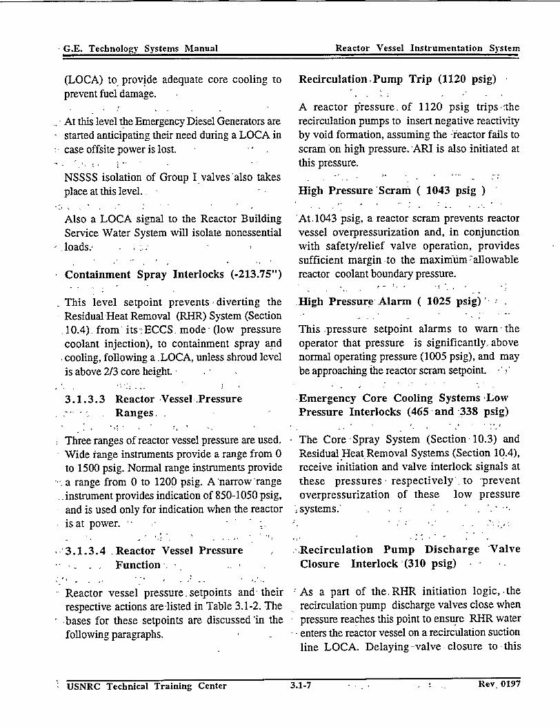
G.E. Technolo2v Systems Manual Reactor Vessel Instrumentation System
(LOCA) to provide adequate core cooling to prevent fuel damage.
At this level the Emergency Diesel Generators are started anticipating their need during a LOCA in case offsite power is lost.
NSSSS isolation of Group I valves'also takes place at this level.
Also a LOCA signal to the Reactor Building Service Water System will isolate nonessential loads.,
Containment Spray Interlocks (-213.75")
This level setpoint prevents, diverting the Residual Heat Removal (RHR) System (Section
,10.4), from its- ECCS. mode (low pressure coolant injection), to containment spray and cooling, following a .LOCA, unless shroud level is above 2/3 core height.
3.1.3.3 Reactor Vessel ,Pressure Ranges,
Three ranges of reactor vessel pressure are used. Wide range instruments provide a range from 0 to 1500 psig. Normal range instruments provide a range from 0 to 1200 psig. A narrow range instrument provides indication of 850-1050 psig, and is used only for indication when the reactor is at power.
'3.1.3.4 -Reactor Vessel Pressure "Function %
Reactor vessel pressure. setpoints and, their respective actions are listed in Table 3.1-2. The " bases for these setpoints are discussed 'in the following paragraphs.
Recirculation, Pump Trip (1120 psig)
A reactor pjressure. of 1120 psig trips,:the recirculation pumps to insert negative reactivity by void formation, assuming the --reactor fails to scram on high pressure.'ARI is also initiated at this pressure.
High Pressure 'Scram ( 1043 psig )
"At. 1043 psig, a reactor scram prevents reactor vessel overpressurization and, in conjunction with safety/relief valve operation, provides sufficient margin to the maximum b allowable reactor coolant boundary pressure.
-High Pressure, Alarm ( 1025 psig) .
This pressure setpoint alarms to warn, the operator that pressure is significantly, above normal operating pressure (1005 psig), and may be approaching ihe reactor scram setpoint.
-Emergency Core Cooling Systems Low Pressure Interlocks (465 and -338 psig)
The Core -Spray System (Section 10.3) and Residual Heat Removal Systems (Section 10.4), receive initiation and valve interlock signals at these pressures respectively' to 'prevent overpressurization of these low pressure systems.
.-Recirculation Pump Discharge Valve Closure Interlock '(310 psig)
*As a part of the, RHR initiation logic;.the recirculation pump discharge valves close when pressure reaches this point to ensure RHR water
- enters the reactor vessel on a recirculation suction line LOCA. Delaying --valve closure to -this
USNRC Technical Training Center £�ev* u±z'i3.1-7 #
G.E. Technologyv Systems Manual Reactor Vessel Instrumentation System
"I USNRC Technical Training Center Riev, I. 0197

G.E. Technology Systems Manual Reactor Vessel Instrumentation System
pressure will ensure the valve will be able to close since it is designed to close with a
,maximum differential pressure of <200 psi.
Residual Heat Removal System (Shutdown, Cooling) Interlock (125 psig)
The shutdown cooling suction isolation valves will automatically be closed above 125 psig in the reactor vessel to protect the RHR pump seals from high temperature cooling water above 125 psig saturated conditions.
3.1.3.5 Trip Signal Devices
Two types of trip signal devices are used for developing trip signal inputs -to various protective system logics: a sensor actuated trip switch, and an analog transmitter trip unit system (ATTUS).
The sensor actuated trip switches are mechanical switches which are actuated by actual movement of the primary sensor's internals (i.e., a bellows or diaphragm for a differential pressure sensor, bourdon tube for a pressure switch). The open/close contact position is the input to the appropriate protective system logic.
"The ATTUS uses an analog sensor which transmits a signal to a trip unit (an electronic bistable) device. The trip unit output is an on/off signal used for protective system logic input. A typical ATTUS block diagram is shown in Figure 3.1-7. An ATTUS consists of master trip units, slave trip units, and a calibration unit.
One, master trip unit is required for each transmitter. The master trip unit has an analog meter-displaying the input signal, produces a trip outputrsignal when the input signal passes through a preset trip point, and produces a gross
failure signal when-the input signal is outside preset high or low limits. The master trip unit also produces two buffered analog output voltages proportional to the input signal. One analog output is used to drive up to seven slave trip units, thereby establishing as many as eight trip points (one for master, seven for slaves) for a single input signal. The second analog voltage, designated the auxiliary analog output, is used to drive external recording or monitoring equipment.
Each slave trip unit is driven by a master trip unit, and adds one additional trip point and gross failure circuit to each sensor channel. The slave trip unit receives a buffered signal proportional to the input signal from a master trip unit. The slave trip unit produces a trip output signal when the input signal passes through a preset trip point; and a gross failure signal when the input signal is outside preset high or low limits.The master and slave trip units can be checked or adjusted in place by a calibration unit, which produces a calibrate command signal and calibration currents. Calibration of any channel (master or slave trip unit) is initiated by the calibrate command signal from the calibration unit to the master trip unit. The signal enables the master trip unit to accept calibration current in place of the input signal and causes the master trip unit gross failure output to generate a gross failure high signal. The calibration current supplied by the calibration unit is made up of independently adjustable stable and transient current sources. The stable current is used to verify or adjust trip points on master or slave trip units, and to check analog signals of master trip units. The- transient current is added to or subtracted from the stable current (depending on the logic selected) to provide a step current for checking time response characteristics of the system equipment.
USNRC Technical Training Center Rev 0197
G.E. Technology Systems Manual Reactor Vessel Instrumentation System
3.1-8

G.E. Technology Systems Manual Reactor Vessel Instrumentation System
3.1.3.6 Reactor Core Flowrate With One Recirculation Pump In Service-'
As discussed in-Section 3.1.2.4, all core flowN except CRD cooling water, passes through the je pumps. This is true only if -both or no recircula tion pumps are running. If only one recirculatio] pump is running, the discharge head of tha recirculation loop's jet pumps will force flow i: reverse through the idle loop's jet pumps. Ti account -for this idle loop flow, core flov summing network is shifted as shown in Figun 3.1-5. If only one recirculation pump is running a -logic network -will -sense this fact, an, disconnect the total core flow recorder from th -normal summer, and connect another. This othe summer will subtract the idle loop flow from thi active loop flow~to give a more representativ -total core flow indication.
3.1.3.7 Jet Pump Flow Effect on Leve Indication
The variable leg of the level sensors for th shroud level range (Figure 3.1-1 and 3.1-2 actually sense pressure at the lower pressure tap of jet pumps 5 and 15. These points are subjec to the jet pump discharge pressure (a dynami head) in addition to the static level of wate above them. This additional pressure cause these sensors to indicate a higher than actual levE whenever there is forced flow through the je pumps.
3.1.3.8 System Interfaces
A short discussion of the interfaces this systen has with other plant systems is given in th paragraphs which follow.
Reactor Vessel System (Section 2.1)
The Reactor Vessel System is the sensing point for the various Reactor Vessel Instrumefitation System sensors.
- Reactor Core Isolation Cooling System n (Section 2.7) t
a :The Reactor Core Isolation Cooling System o receives initiation and trip, signals from the v Reactor Vessel Instrumentation System.
,, Feedwater Control System (Section 3.2) d
e, The Feedwater Control System receives vessel ýr level signals' for -control, and vessel pressure
e signals for display from the Reactor Vessel e ,Instrumentation System.'
Nuclear Steam Supply Shutoff System I -(Section 4.4).
'The Nuclear Steam Supply Shutoff System e receives vessel level trip logic input signals from ) the Reactor Vessel Instrumentation System. S
:t Recirculation Flow Control System c (Section 7.2) ;r s The Recirculation Flow Control System receives d1- level and pressure trip signals for Recirculation t Pump trips from the Reactor Vessel Instrumenta
,tion System.-.
-Reactor, Protection System (Section 7.3)
a The Reactor Protection System receives level and e -pressure trip input'signals for scram and scram
bypass functions: from the Reactor Vessel Instrumentation System.:r . "I
USNRC Technical Training Center 3.1-9 Rev 0197
G.E. Technology Systems Manual Reactor Vessel Instrumentation System
- USNRC Technical Training Center S 3.1-9 Rev 0197

G.E. Technology Systems Manual
Emergency Core Cooling System (Chapter 10)
The Emergency Core Cooling Systems receive initiation signals from the Reactor Vessel Instrumentation System.
3.1.4 BWR Differences
The discussion in this section is typical for plants of the BWR/4 product lines. The actual setpoints are specific to one facility and differ from plant to plant. Other BWR product line plants have systems similar to the one described in this section. The terminology associated with the various water level conditions is different for the older plants. For example the Level 3 setpoint is called "low level"; the Level 2 setpoint is called "low low level"; and the Level I setpoint is called "low low low level."
One additional difference that can be found in any of the product lines is that the fuel zone range of reactor water level instrumentation uses the top of active fuel (TAF) as instrument zero instead of the same instrument zero that the other ranges utilize.
3.1.5 PRA Insights
The Reactor Vessel Water Level Instrument System is a major contributor to core damage frequency for the reactor vessel instrument cut set sequence. Flashing of a reactor vessel water level instrument reference leg would a false high level reading that could cause a turbine trip. A reactor SCRAM would then be generated if the turbine power was-above 30%. Additional equipment failures could then leadto core damage. This sequence is attributed to 5% of the core damage frequency at Shoreham.
3.1.6 Summary
Classification - Safety related system. (Those sensors and components controlling safety systems and safety related systems). Purpose - To provide information on reactor vessel parameters to allow safe operation. To provide initiation signals for safety systems.
Components - Level, pressure, temperature and flow sensors. Master Trip Units, Slave Trip Units, Calibration Units. Indicators and Recorders.
System Interfaces - Reactor Vessel System; Reactor Core Isolation Cooling System; Feedwater Control System; Nuclea- Steam Supply Shutoff' System; Offgas System; Recirculation Flow Control System; Reactor Protection System; Emergency Core Cooling System.
u31�ni... iecnnicai iraining Center 3.1-10Rev 01973.1-10
--- - .Reactor, na ao•l£t~|UmnLaLilon Systen•
1USNtt.C Iechnncal I raining C~enter
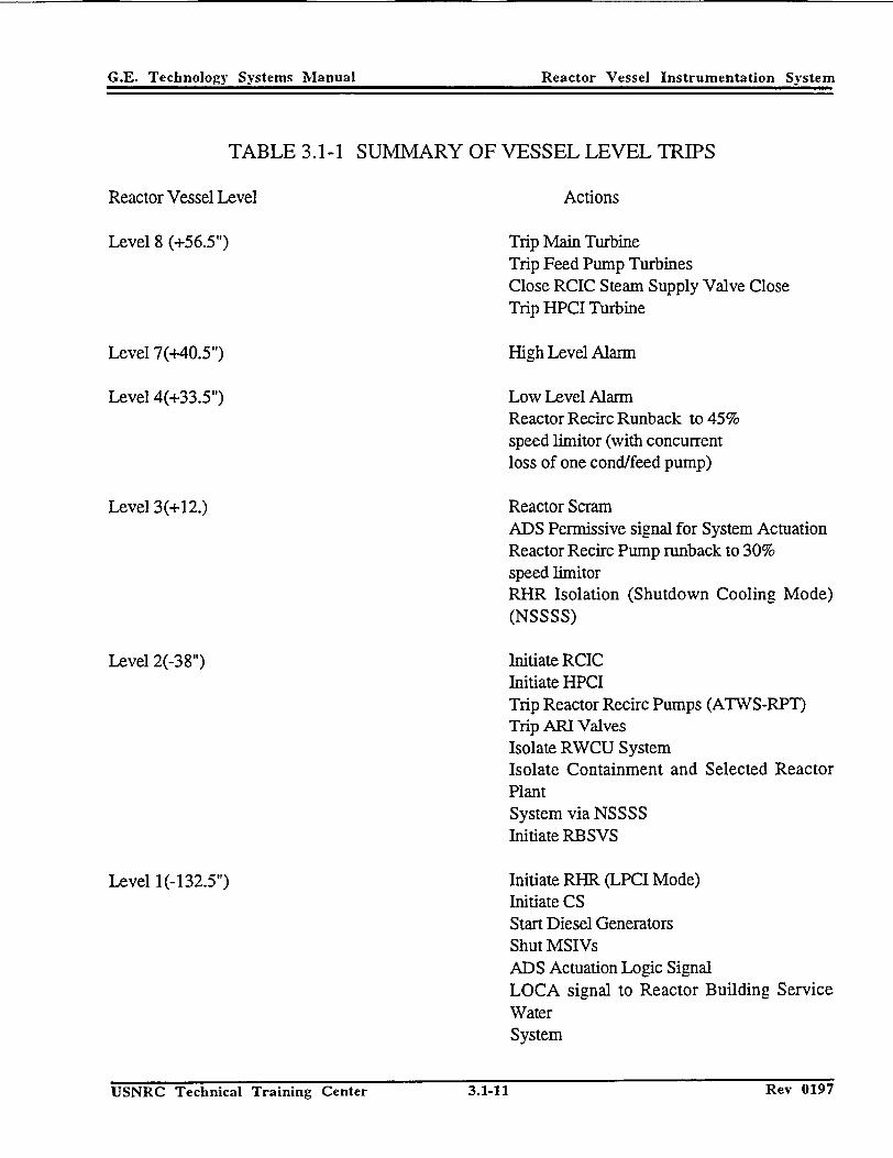
TABLE 3.1-1 SUMMARY OF VESSEL LEVEL TRIPS
Reactor Vessel Level Actions
Level 8 (+56.5") Trip Main Turbine Trip Feed Pump Turbines Close RCIC Steam Supply Valve Close Trip HPCI Turbine
High Level AlarmLevel 7(+40.5")
Level 4(+33.5") Low Level Alarm Reactor Recirc Runback to 45% speed limitor (with concurrent loss of one cond/feed pump)
Level 3(+12.)
Level 2(-38")
Reactor Scram ADS Permissive signal for System Actuation Reactor Recirc Pump runback to 30% speed limitor RHR Isolation (Shutdown Cooling Mode) (NSSSS)
Initiate RCIC Initiate HPCI Trip Reactor Recirc Pumps (ATWS-RPT) Trip ARI Valves Isolate RWCU System Isolate Containment and Selected Reactor Plant System via NSSSS Initiate RBSVS
Initiate RHR (LPCI Mode) Initiate CS Start Diesel Generators Shut MSIVs ADS Actuation Logic Signal LOCA signal to Reactor Building Service Water System
Level 1(-132.5")
USNRC Technical Training Center 3.1-11 Rev 0197
G.E. Technology Systems Manual Reactor Vessel Instrumentation System
Rev 0197USNRC Technical Training Center 3.1-11

G.E. Technology Systems Manual Reactor Vessel Instrumentation System
TABLE 3.1-2 SUMMARY OF REACTOR PRESSURE SETPOINTS
Reactor Vessel Pressure Actions
RHR Isolation (Shutdown Cooling Mode)
Auto close Recirculation Pump discharge valve, during LOCA
465 psig & 338 psig Permissive for injection by CS and RHR, during LOCA
1025 psig High pressure alarm
1043 psig High pressure reactor scram
Trips Reactor Recirc Pumps (ATWS-RPT) Trip ARI Valves
USNRC Technical Training Center 3.1-13 Rev 0197
125 psig
310 psig
1120 psig
Rev 0197USNRC Technical Training Center 3.1-13
G.E. Technology Systems Manual Reactor Vessel Instrumentation System

Geneal lecric ecbolov Sytem MaualReactor Vessel Instrumentation Sysqtem
TABLE 3.1-3 NARROW RANGE LEVEL INTERLOCKS
LEVEL ACTUATION INSTRUMENT AND LOGIC
Level 8 (56.5") Main Turbine Trip LT008 A, B, C, RFPTs Trip 2 out of 3
High Level Trip Alarm LT008 A, B, C,
RCIC Steam Supply Valve 1 out of 1 Closes 159A and 157B
2 out of 2
HPCI Trip 159B and 157A 2 out of 2
Level 7 (40.5") High Level Alarm LT008 A or B 1 out of 1
Level 4 (33.5") Low Level Alarm LT008 A or B 1 out of 1
Reactor Recirculation LT008 A or B Runback to 45% speed 1 out of 1 limitor (with concurrent loss of one feed pump, condensate booster pump, or condensate pump)
Level 3 (12.5") Reactor Scram LT 154 A, B, C, D A or C and B or D
NSSSS Isolation (RHR S/D LT154 A, B, C, D Cooling) A and B INBD
C and D OUTBD
ADS Permissive LT159 A, B
Reactor Recirculation LT008 A or B Runback to 30% speed 1 out of 1 limitor.
USNRC Technical Training Center 3.1-15 Rev 0100Rev 0100
General Electric Technoloe-v Systems Manual
USNRC Technical Training Center 3.1-15

G.E. Technology Systems IvIanual Reactor Vessel Instrumentation System
TABLE 3.1-4 WIDE RANGE LEVEL INTERLOCKS
LEVEL ACTUATION INSTRUMENT
AND LOGIC
Level 8 (56.5") HPCI Trip LT 157 A, B
RCIC Steam Supply Valve Closes HPCI 157 A and 159 B
RCIC 157 B and 159 A
Level 2 (-38") Start HPCI and RCIC LT 157 A, B, C, D
RCICIHPCI 157
A and C or B and D
Trips Recirculation Pumps LT 157 A, B, C, D
(ATWS-RP'D, Trip ARI Valves RPT 3A (B) ARI OA, A and C
RPT 4A (B) ARI OB, B
andD
RBSVS Initiation LT 155 A, B, C, D
A and B or C and D
LEVEL 1 (-132.5") Group I Isolation LT 155 A, B, C, D
AandB or C andD
Start Emergency Diesels LT 157 A, B, C, D
EDG 101, 103 A and C
EDG 102, 103 B and D
Initiate Core Spray (via Bus LT 157 A, B, C, D
Loading Program) EDG 101, 103 A and C
EDG 102,103 B and D
Initiate LPCI (via Bus Loading LT 157 A, B, C, D
Program) EDG 101, 103 A and C EDG 102,103 B and D
Permissive signal to ADS LT 157 A, B, C, D
A-AandC
B-B andD
LOCA Signal to Service Water LT 157 A, B, C, D
A and C or B and D
Feedwater Inlet Check Valves Discs LT 157 A, B, C, D
Released A and C or B and D
USNRC Technical Training Center 3.1-17 Rev 0197
G.E. Technology Systems Manual Reactor Vessel Instrumentation System
Rev 0197USNRC Technical Training Center 3.1-17

Shutdown
200 Range
S~~~~~~Main Steam Nozzle640"_•]Nro ie l
Leve#8 73"Narrow Wide
Normal Level 554" Ran Range ._Lyel #4 55o" Y 6_'
Level #3 529"
Instrument "0" 517" 0 _ _ Core Spray Nozzle 484"4 " (Typ 3)
N " e 48 Fuel Zone
Feedwater Nozzle 483", Range
zz 3 Level #1 384." "0
Level #2 479" Top of Actice Fuel 358".150 (Typ 2) - - - - - - - - 18
2/3 Core Covered 303" .308 1
Bottom of Active Fuel 208"
*308
Jet Pump Instrument Tapl %" _
SLC Nozzle and Instrumentation Tap 94"
Inside Bottom Head 0"
Figure 3.1-1 Vessel Level Instrumentation Ranges 03)

Figure 3.1-2 Reactor Vessel Level and Pressure Instrumentation
LT PT
LjIC32LT (00• A&C
0 CD C)

019 A-V
RPV
Located on Bottom Drain Line
Figure 3.1-3 Vessel Temperature Monitoring
3.1-23
0796
Drywell Wall
. Drywell Penitration
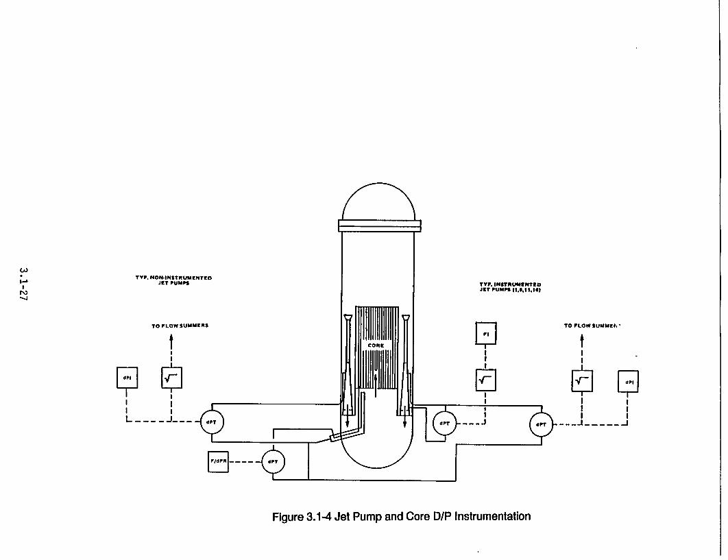
TYP. NON-INSTRUMENTEO JET PUMPS TVP. INST It.6ItNTED
JET PUMPS |,,11,01.i|
TO FLOW SUMMERS
t
I-
TO FLOW SUMMEt t
Figure 3.1-4 Jet Pump and Core DIP Instrumentation

LOOP A LOOP B JET PUMPS
12 2 12
4uu ,-j F, H I - I LOOP B_____ 14
FLOW FLOW
A#
B'
19
-Ei~z20
A - SHUTIFPUMPAOFFANDPUMPBON B - SHUTIFPUMPBOFFAND PUMPAON
A' - SHUT IF PUMPA ON OR PUMPBOFF
B' - SHUTIFPPUMPAOFFORPUMPBON
CORE FLOW
Figure 3.1-5 Core Flow Summing Network
10
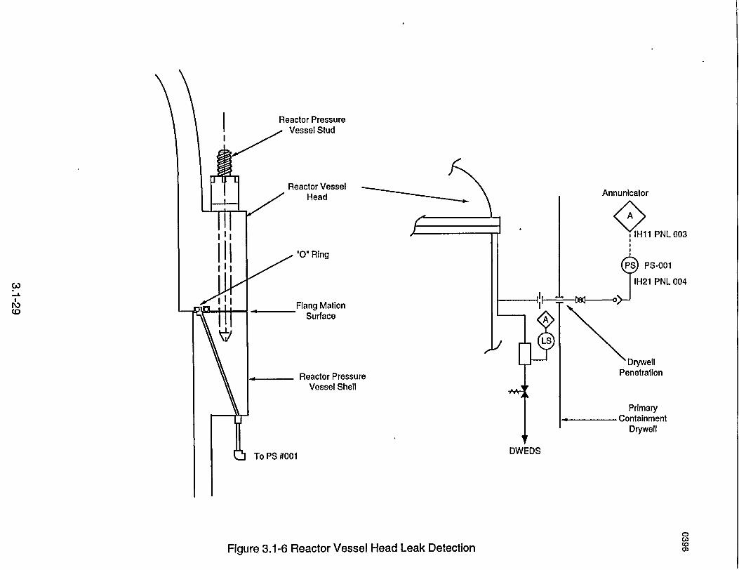
Reactor Pressure Vessel Stud
Reactor Vessel - Head
Figure 3.1-6 F
Annunicator
IHMl PNL 603
"0" Ring I
:• __.•o/• IH21 PNL 004
Flang Mation II 0
Surface A
LS
Drywell
Reactor Pressure Penetration Vessel Shell
Primary Containment
Drywell
DWEDS
Va Reactor Vessel Head Leak Detectionf.

GROSS TRIP FAILURE OUTPUT ALARM
Figure 3.1-7 Analog Transmitter Trip Unit System Block Diagram
TEST SIGNALr
LOCAL REMOTE
TRIP OUTPUT
Boiling Water Reactor GE BWR/4 Technology
Technology Manual
Chapter 3.2
Electro Hydraulic Control System

G.E. Technology Systems Manual Electro Hydraulic Control
Table of Contents 3.2 ELECTRO HYDRAULIC CONTROL SYSTEM ............................... 1
3.2.1 Introduction ................................................................................... 1
3.2.2 Component Description ........................................................................... 2
3.2.2.1 Pressure Control Unit .................................................................. 2
3.2.2.2 Speed Control Unit ...................................................................... 2
3.2.2.3 Desired Load Control Unit ............................................................... 3
3.2.2.4 Valve Control Unit ....................................................................... 3
3.2.2.5 Hydraulic Power Unit .................................................................. 4
3.2.2.6 Emergency Trip System ................................................................ 4
3.2.3 System Features and Interfaces ................................................................. 5
3.2.3.1 Chest and Shell Warming .............................................................. 5
3.2.3.2 Turbine Roll ............................................................................. 6
3.2.3.3 Normal Operation ........................................................................ 7
3.2.3.4 Plant Shutdown and Cooldown ........................................................ 7
3.2.3.5 EHC Testing ............................................................................. 8
3.2.3.6 Turbine Trips ............................................................................ 8
3.2.3.7 Pressure Regulator Failures ........................................................... 8
3.2.3.8 System Interfaces ........................................................................ 9
3.2.4 BWR Differences ............................................................................... 10
3.2.5 Summary ....................................................................................... 10
List of Tables 3.2-1 Turbine Trip Conditions ......................................................................... 11
List of Figures
3.2-1 Electro Hydraulic Control System Logic ......................................................... 15
3.2-2 Pressure Control Spectrum ......................................................................... 17
3.2-3 EHC System Controls ................................................................................ 19
3.2-4 EHC System Hydraulic Power Unit ............................................................... 21
3.2-5 EHC Fluid Supplies ................................................................................ 23
3.2-6 Emergency Trip System ............................................................................. 25
3.2-7 Turbine Roll .......................................................................................... 27
n -n 7JRev: J.71USNRC Technical Training Center 3.2-i
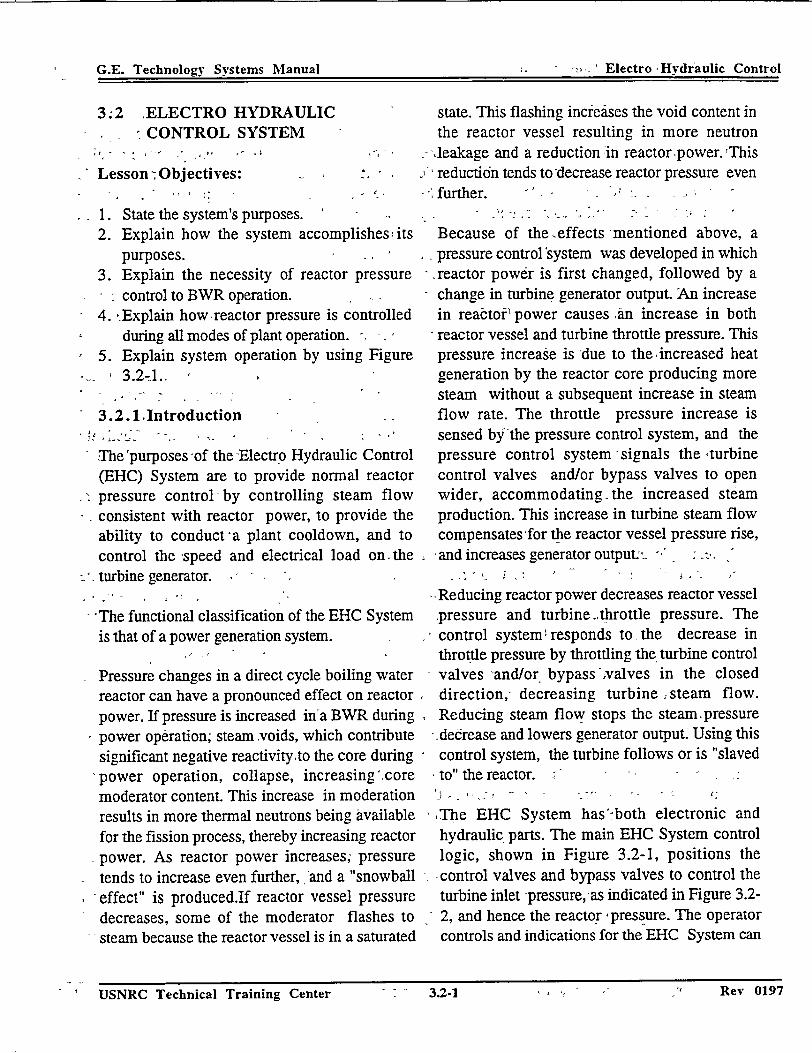
G.E. Technology Systems Manual Electro Hydraulic Control
3.2 ELECTRO HYDRAULIC - " CONTROL SYSTEM
Lesson Objectives:
1. State the system's purposes. 2. Explain how the system accomplishes: its
purposes. .,
3. Explain the necessity of reactor pressure . ccontrol to BWR operation. 4.-.Explain how, reactor pressure is controlled
during all modes of plant operation. 5. Explain system operation by using Figure
3.2.1 Introduction
The'purposes -of the -Electro Hydraulic Control _(EHC) System are to provide normal reactor Spressure controlby controlling steam flow
consistent with reactor power, to provide the ability to conduct'a plant cooldown, and to control the 'speed and electrical load on.the
- turbine generator.
"-The functional classification of the EHC System is that of a power generation system.
Pressure changes in a direct cycle boiling water reactor can have a pronounced effect on reactor power. If pressure is increased in a BWR during power operation; steam .voids, which contribute significant negative reactivityto the core during power operation, collapse, increasing' core moderator content. This increase in moderation results in more thermal neutrons being available for the fission process, thereby increasing reactor power. As reactor power increases; pressure tends to increase even further, and a "snowball
-effect" is produced.If reactor vessel, pressure decreases, some of the moderator flashes to steam because the reactor vessel is in a saturated
state. This flashing increases the void content in the reactor vessel resulting in more neutron
*--leakage and a reduction in reactor power. 'This 7 reduction tends to-decrease reactor pressure even --;further. ..
Because of the -effects mentioned above, a * pressure control'system was developed in which .reactor power is first changed, followed by a change in turbine generator output. An increase in reactorF power causes an increase in both reactor vessel and turbine throttle pressure. This pressure increase is due to the.increased heat generation by the reactor core producing more steam without a subsequent increase in steam flow rate. The throttle pressure increase is sensed by'the pressure control system, and the pressure control system -signals the •turbine control valves and/or bypass valves to open wider, accommodating the increased steam production. This increase in turbine steam flow compensates'for the reactor vessel pressure rise, and increases generator output: ,
, Reducing reactor power decreases reactor vessel pressure and turbine. throttle pressure. The control system responds to the decrease in throttle pressure by throttling the turbine control valves 'and/or bypass Nalves in the closed
- direction, decreasing turbine steam flow. Reducing steam flow stops the steam pressure decrease and lowers generator output. Using this
" control system, the turbine follows or is "slaved to" the reactor.
,The EHC System has'-both electronic and hydraulic parts. The main EHC System control logic, shown in Figure 3.2-1, positions the "-control valves and bypass valves to control the turbine inlet -pressure,,as indicated in Figure 3.22, and hence the reactor pressure. The operator controls and indications for the EHC System can
USNRC Technical Training Center 3.2-1 Rev 0197- 3.2-1
G.E. Technology Systems Manual :. ... 'ElectroýHydr~aulic Control
ý USNRC Technical Training Center "*Rev 0197
G.E T. Electro draulic Control
be seen in Figure 3.2-3.
In addition to normal control of the control valves and bypass valves by electronic and hydraulic networks, the EHC System also contains the electronic and hydraulic components necessary for positioning control of the intercept valves and trip control of the control valves, intercept valves, stop valves, and intermediate stop valves. The EHC System hydraulic power unit is shown in Figure 3.2-4 while the various fluid supplies are shown in Figure 3.2-5. Figure 3.2-6 shows the Emergency Trip System for the turbine.
3.2.2 Component Description
The major components of theEHC System are discussed in the paragraphs which follow.
3.2.2.1 Pressure Control Unit
The pressure control unit is part of the main EHC System logic and is shown in the lower left hand comer of Figure 3.2-1. There are two pressure regulators, A and B. The pressure regulators are the proportional type which require a 30 psi difference between turbine inlet pressure and the pressure setpoint (pressure error) to open the control valves to the 100 percent position. Therefore, the pressure at the turbine inlet varies 30 psi from 0 percent power to full power, or 3.33% flow/psi. This effect is shown in Figure 3.2-2: Also shown in this figure is a curve for reactor vessel pressure. This curve is not linear, primarily because of pressure drops (across the flow restrictors, MSIVs, and steam line piping) which are proportional to the flow squared.
The relationship between pressure error and steam flow' was determined by experimentation and gives a rapid response' which is relatively stable.
The pressure regulators compare the turbine inlet or throttle pressure with the pressure setpoint (normally set at 920 psi) and generate a valve position demand based on the error. If throttle pressure is less than or equal to the pressure setpoint, the control valves and bypass valves receive a fully closed demand from the pressure control unit.
Each pressure regulator, A and B, have two summers associated with them. The first summer for each pressure regulator receives the pressure setpoint signal (adjustable by increase and decrease pushbuttons) and a bias signal which are algebraically summed. The bias signal for the A regulator is 0 psig while the bias signal for the B regulator is +3 psi. This effectively places the. A' regulator in control and the B regulator in standby. The outputs of these first summers are sent to another set of summers where the steam throttle pressure signals are algebraically summed with the output of the first regulator. The outputs of the two pressure regulators are then sent to a high value gate which passes only the highest positive value of its two inputs. The signal from the A regulator is normally 3 psi greater than the signal from the B regulator because of different bias inputs to the pressure regulators. The output of the high value gate (HVG) is then sent to the pressure-% flow gain amplifier so that the pressure error signal can be converted to an equivalent % steam flow demand signal. The gain at this amplifier is 3.33% steam flow for each 1 psi pressure error.
3.2.2.2 Speed Control Unit
The speed control unit is shown in the upper left comer of Figure 3.2-1. It receives two speed signals from turbine shaft speed pickups and compares them to an operator chosen speed reference signal to produce two speed error
USNRC Technical Training Center 3.2-2 Rev 0197Rev 0197
G.E. Technology Systems Manual
USNRC Technical Training Center 3.2-2
('.�F. Technolo�v Systems Manual Electro Hydraulic Control
signals. The speed control unit differentiates one -of the speed signals to produce an acceleration signal which is compared to an operator chosen acceleration reference signal. The acceleration error signal is -then integrated and sent to a low value gate along with the two speed error signals -to produce an output to the load control unit.,The signal out of the low value gate is the one which requires the smallest control valve opening. The
¾, speed setpoint and acceleration setpoint are
selected by the operator using pushbuttons.
-3.2.2.3, Desired Load Control Unit,
-The major part of the load control unit is the load ---set motor.- The position of the motor is used to
compute the final value of desired load called the - load reference value. Once the load set motor-has been moved'one way~or the other and stopped, the load set remains constant until such time as the load set motor is again moved. The operator can control the position of the load set motor by using the load selector increase or decrease pushbuttons.-: .,
- The load set motor has a runback circuit which energizes the motor, under certain conditions, to
-run the load reference value down to zero. A runback to zero -will occur any time synchronous
'speed (1800 rpm) is not the speed selected by the , operator. This ensures that the speed control unit controls the turbine acceleration rate on a turbine roll. Another condition which causes a runback "is the load reject circuit. The load reject circuit
'.senses turbine powerby measuring HP turbine -exhaust pressure or crossover -pressure, and
generator load by measuring generator 'stator . amps. Whenever -the load reject circuit sees a mismatch of ,40%, a load rejection has occurred, and the load set motor runs back toward zero as
- long as the mismatch exceeds 40%. This feature "gives an electronic follow up close signal to the
control -valves, which are also :hydraulically tripped closed by the load rejection. Finally, a loss of stator cooling signal will also cause the runback circuit to be activacted. This runback is actuated by low inlet water pressure (<13 psig) or high outlet water temperature (>95"C) inz'the Stator Cooling Water System. The loss of stator
- cooling signal insures proper cooling is available to cool the generator stator by causing a runback .to 25% power with a 0.9,power factor or to 5811 stator amps.. The load set •value is always
,summed withanysignal- which may be coming from the speed control unit. ,- ,..
There is also a line speed matcher circuit with the Load Control Unit. When selected, it positions the load set motor to adjust turbine generator speed tosynchronize the generator. frequency with that of the grid. The operator must manually close the' main generator output breaker-to complete paralleling to the grid.
3.2.2.4 Valve Control Unit
The valve control unit establishes -the steam flow demand signals to the control valves and to the bypass valves.-An integral part of.the valve control unit is the pressure/ load low valve gate. The pressure/load low yalve gate receives signals from the pressure control unit,-the speed control unit,--the desired.load, control unit, the load
-•limiter, and the maximum combined flow limiter. The values of the load limit and the maximum combined flow limit are determined by manual potentiometers. ,The load limit value establishes -the maximum amount of rated reactor steam, flow
- which is allowed ,to go to the turbine -and is normally set at -100%. The maximum combined
flow limit establishes the maximum amount of - rated reactor steam flow which is allowed to go
to the combination of the turbine and the bypass valves.
- i{ev UIYi
USNRC Technical Training Center 3.2-3.- USNRC Technical Training Center , -3.2-3
Electro Hydraulic ControlI .G Technology Systems Manual
-,. Rev 0197

G.E.Tecnoloy Sstem MaualElectro, Hvdraulic Conntrol
The maximum combined flow limit is normally set at 105% on the potentiometer.
The output of the pressure/load low value gate is the control valve demand. This low value gate is the device which makes the turbine a slave to the reactor. The bypass valve demand is established by comparing the pressure/load low value gate output to the pressure control unit output. Any difference is sent to a low value gate which also receives the difference between the- maximum combined flow limit and the control valve demand. A bypass valve demand can be artificially created independent of pressure/load conditions by means of the cooldown bypass jack. That device is used during normal cooldowns of the plant after the reactor is shutdown. The bypass valve demand is automatically adjusted to zero if condenser vacuum drops to a very low value (<7" hg).
3.2.2.5 Hydraulic Power Unit
The EHC hydraulic power unit, shown in Figure 3.2-4, provides high pressure hydraulic fluid which is divided into several different oil supply paths to various steam valves. The different oil paths' are necessary to effect specific valve responses for pressure control and turbine protection. Pressure control is effected by positioning the control valves and bypass valves. Turbine protection against many potentially unsafe conditions for the turbine is provided by turbine trips, which are rapid closures of the stop valves accomplished by durmping the hydraulic fluid pressure which previously kept the valves open. Large springs rapidly close the stop valves when the hydraulic oil pressure is removed. The intermediate stop valves also trip closed on turbine trips in the same manner as the main stop valves.
The control valves are tripped closed upon a load rejection sensed by the load reject circuit as discussed in section 3.2.2.3.
The intercept valves, normally fully open, are throttled using hydraulic fluid under certain overspeed conditions to provide turbine protection.
The hydraulic power unit consists of a fluid reservoir, pumps, fluid coolers, strainers, filters, and accumulators. The pumps are motor driven, variable delivery, piston' pump's. Normally one pump is running with the other in standby. If the running pump fails, the standby pump will 'automatically start when system pressure decays. The hydraulic drain lines from the various steam valves are routed through tube and shell coolers which are cooled by the Turbine Building Closed Cooling Water System.
Fluid Supplies
There are five major hydraulic fluid streams developed by the hydraulic power unit. The five different streams are necessary to cause specific valve responses for pressure control and turbine protection.- These fluid streams and the affected valves can be seen in Figure 3.2-5. The Fluid Actuator Supply (FAS) is directed to'the combined intermediate stop valves, the bypass valves, and the main stop valves as a fluid which actuates the movable pistons of these valves. The Fluid Jet Supply (FJS) is a high pressure fluid which is directed to the bypass valves, the main stop valve number two, the control valves, and intercept valves 1, 3, and 5. The FJS controls how the actuating oil (FAS- or Fluid Actuator Supply Trip Control (FASTC) -is applied. The Emergency Trip Supply (ETS) is directed to the combined intermediate stop valves and the main stop valves as a fluid stream which
USNRC Technical Training Center 3.2-4 Rev 01973.2-4 Rev 0197
G.E."•Technology Systems ManualL
USNRC Technical Training Center
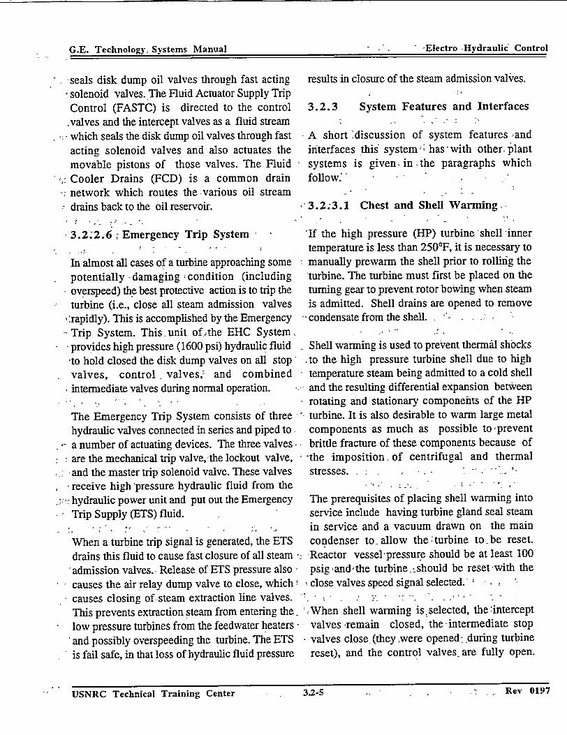
G.E. Technolof~v, Svstems ManualElcr HralcCotl
-seals disk dump oil valves through fast acting -solenoid valves. The Fluid Actuator Supply Trip Control (FASTC) is directed to the control
,valves and the intercept valves as a fluid stream - which seals the disk dump oil valves through fast acting solenoid valves and also actuates the movable pistons of those valves. The Fluid
, Cooler Drains (FCD) is a common drain network which routes the.various oil stream drains back to the oil reservoir.
3.2 -2.6 Emergency Trip System
In almost all cases of a turbine approaching some potentially damaging condition (including overspeed) the best protective action is to trip the turbine (i.e., close all steam admission valves
,,rapidly). This is accomplished by the Emergency -Trip System. This. unit of the EHC System,
provides high pressure (1600 psi) hydraulic fluid ýto hold closed the disk dump valves on all stop valves, control valves, and combined intermediate valves during normal operation.
The Emergency Trip System consists of three hydraulic valves connected in series and piped to. a number of actuating devices. The three valves are the mechanical trip valve, the lockout valve, * and the master trip solenoid valve. These valves -receive high pressure hydraulic fluid from the hydraulic power unit and put out the Emergency Trip Supply (ETS) fluid.
When a turbine trip signal is generated, the ETS drains this fluid to cause fast closure of all steam admission valves.- Release of ETS pressure also causes the air relay dump valve to close, which causes closing ofsteam extraction line valves. This prevents extraction steam from entering the low pressure turbines from the feedwater heaters
'and possibly overspeeding the turbine. The ETS "is fail safe, in that loss of hydraulic fluid pressure
results in closure of the steam admission valves.
3.2.3 System Features and Interfaces
A short :discussion of system features land interfaces this system' has, with other. plant systems is given, in. the paragraphs which follow:
"3.2;3.1 Chest and Shell Warming.
"If the high pressure (HP) turbine shell,'inner temperature is less than 250'F, it is necessary to manually prewarm the shell prior to rollirig the turbine. The turbine must first be placed on the turning gear to prevent rotor bowing when steam is admitted. Shell drains are opened to remove
-,condensate from the shell. -" .
Shell warming is used to prevent thermal shocks .to the high pressure turbine shell due to high temperature steam being admitted to a cold shell and the resulting differential expansion between rotating and stationary components of the HP turbine. It is also desirable to warm large metal components as much as possible to ,prevent brittle fracture of these components because of -the imposition, of centrifugal and thermal stresses. .
The prerequisites of placing shell warming into service include having turbine gland seal steam in service and a vacuum drawn on the main condenser to-allow the,-turbine to-be reset. -Reactor vessel pressure should be at least 100 psig andthe turbine, -should be reset with the close valves speed signal selected.'
,.When shell warming is selected, the :intercept valves ,remain closed, the intermediate stop valves close (they were opened: during turbine reset), and the control valves are fully open.
USNRC Technical Training Center 3.2-5 Rev IJIYlUSNRC Technical Training Center 3.2-5
". -,Electro -Hydraulic' Control
R, l ev 0197

G.E. Technology Systems Manual
Crossover steam line drain valves are closed to permit shell pressurization. These valves are, interlocked open anytime a, close valves speed signal is present. Selection of shell warming overrides the open interlock. All other main steam line drain valves remain open and do not impede shell pressurization because of the capacity of the #2 stop valve (SV) internal bypass. The bypass is capable of passing up to twice the steam flow'required to maintain the turbine at rated speed with no load on the generator. The HP turbine shell is pressurized to between 60 and 100 psig via adjustment of the #2 MSV internal bypass without rolling the turbine off the turning gear and allowing the shell to "soak" until the desired temperature is reached.
When the HP shell is warmed up, chest warming can be used to pressurize the steam chest between the SVs and CVs. This is accomplished by pressing the decrease pushbutton until the off light under shell/chest warming illuminates, then deselecting shell warming and selecting chest warming. The turbine control valves then close and the intermediate stop valves open. By pressing the increase pushbutton, steam is admitted to the chest through the #2 SV bypass valve, pressurizing the chest to reduce the differential pressure across the MSV's in preparation for rolling the turbine.
3.2.3.2 Turbine Roll
The turbine is rolled by selecting, the proper startup rate depending on HP turbine shell inner temperature, and selecting the desired speed (usually 1800 rpm). When this is done several events take place. The speed error was zero while the close valve speed was selected and, the acceleration demand signal was saturated high because one of the startup rates must always selected. When the speed is selected, the two
sections switch output- The speed control section now demands full open control valves.
The acceleration control section, due to a capacitive feedback (not shown) demands full closed control valves.
As the capacitor discharges, feedback is reduced and the acceleration control signal increases until it is demanding enough steam flow to accelerate the turbine at the desired rate. At speeds in the vicinity of 1800 rpm, a 3.6 rpm (.2%) speed error is required for a 180 rpm, per minute acceleration rate. This produces approximately 4% steam flow demand to the control valves. When turbine speed reaches approximately 1796 rpm, the speed control section output error has decreased enough to take control via the low value gate (LVG). The acceleration control error signal continu6us increasing to positive saturation. A speed error signal is approximately 1.8 rpm (.1%) is necessary to keep the turbine rolling at or near rated speed. This speed error corresponds to approximately 2% steam flow demand.
Figure 3.2-7 graphically illustrates the preceding discussion. At time 0, the acceleration: control section output is in positive saturation due to zero turbine, acceleration and an acceleration demand (assume 180 rpm per minute) is present. The all valves close speed is selected so speed control summing junction output is in negative saturation, and turbine rpm is zero.
At time Ti the operator selects 1800 rpm. This causes three actions: the large speed errorjust introduced causes the speed control summing junction output to go to positive saturation, the capacitive feedback to the acceleration circuit integrator input drives its output into negative saturation; and as the capacitor discharges, the
USNRC Technical Training Center 3.2-6 Rev 0197Rev 0197
I
-A AV Electro 14 I-Iic I- + I,I
USNRC Technical Training Center 3.2-6

G.E. Technology Systems Manual Electro Hydraulic Control
existing acceleration error signal begins to increase the integrator output.
At time T2, the"'integrator output becomes positive. This causes the control valves to begin
.opening and the turbine to start to accelerate. The integrator output increases until -the desired
-,acceleration rate is attained and continues to increase ashiall amount as necessary to maintain this' ac-eleration rate constant as turbine speed
,'increases.
At T3, the small speed error signal has caused the summing junction output to decrease until it "becomes the controlling signal, and the turbine ,acceleration decrease causes the acceleration
•'integrator output to go into positive saturation. The summing junction output is now a small
* positive value which is enough tO maintain' the turbine at a constant speed.
In order to bring the turbine to 1800 rpm for
synchronizing, ýthe operator would use the line
:speed matching switch or the load selector increase pushbutton to increase steam flow demand.
If any speed other than 1800 rpm is desired, the "final turbine speed will be approximately (slightly less ,than) the' selected 'speed and thetime required to reach that speed is less. In addition, the load selector cannot be used to increase speed unless 1800 rpm is selected -because of the runback on the load set- motor when
"• synchronous speed is not selected.
3.2.3.3 Normal Operation
In the normal mode 'of operation -with reactor thermal power at 100% and the generator loaded to 100% capacity, a listing of the parameter and controller setpoint values follows:
Reactor power 2436 MWt Generator power 880 MWe Reactor pressure ' 1005 psig 'Throttle pressure 950 psig Pressure setpoint 920 psig
' Maximum combined flowlimit 105% Load limit 100% Turbine speed 1800 rpm Load set -. 100%
The main stop valves are fully open, and-the control valves are passing 100% rated steam flow. Both combined intermediate valves (the intercept valve and the stop valve) are fully open supplying low pressure steam to the low pressure turbines.
-The pressure 'error signal is' 30 psi which corresponds to a 100% control valve open demand and th6 control valves are under pressure control. Generatoi power changes are made by "first changing reactor power and then allowing the pressure change due to the power change to reposition the control valves for the new generator output.
Assume that the operatdr desires to reduce the reactor power to - 80%. The core flow corresponding -to 80% -reactor power is determined; and-the control room operator then
-starts reducing recirculation flow to reduce core "flow to achieve the 80% reactor power. As flow is decreased, more boiling occurs in the core which 'causes -reactor power- and the -steam generation rate to decrease. The control valves are still initially passing 100%'steam flow. As the reactor attempts to continue to generate 100% steam flow, moderator temperature and pressure 'decrease. As pressure decreases, pressure error decreases and the control valves begin to close. As the control valves close, the .pressure
Sdecrease is slowed because reactor steam flow is
USNRC Technical Training Center 3.2-7 Rev (1197
S: , Electro Hydraulic ControlG.E. •Technology •Systems Manual
Rev 0197USNRC Technical Training Center 3.2-7

G.E. -Technology Systems Manual
"catching up" with control valve position. Finally at 944 psig turbine throttle pressure, the pressure error is reduced to 24 psi which calls for 80% steam flow and corresponds to the steam generation rate the reactor can provide while maintaining criticality, and pressure no longer decreases. Final conditions are reactor power 80%, turbine steam flow 80%, throttle pressure 944 psig, and pressure error 24 psi. Note that neither the desired load control unit nor the speed control unit played any part in the, change.
3.2.3.4 Plant Shutdown and Cooldown
The turbine generator is normally unloaded prior to shutting it down. Reactor power is decreased to a point well below the bypass valve capacity (5% generator load), and then the turbine trip pushbutton is depressed. The main stop and control- valves fast close, the combined intermediate (stop and intercept) valves close, and the bypass valves open in response to the valve control logic. The bypass, valves then control reactor pressure. When the reactor is shutdown, the cooldown rate of the reactor vessel can be controlled by using the bypass jack (sometimes called the cooldown bypass jack) or by reducing the pressure setpoint. This causes more or less steam to be passed to the condenser, thus controlling the depressurization rate of the reactor vessel. If pressure decrease is controlled in the saturated system, this then also controls the temperature decrease (or cooldown rate).
3.2.3.5 EHC Testing
Controls and indicators are provided on the bypass valve and pressure control panel so that each of the four bypass valves can be individually cycled through an opening and closing test sequence to check for proper
operation. Only one valve can be tested at a time. A bypass valve is fully cycled (fast opening the last 10% of travel) by selecting the desired valve and then depressing the BPV test pushbutton.
Main turbine: valves can be tested from the turbine control panel. A test switch for each control, valve (CV), stop valve (SV), - and combined intermediate valve (CIV) is provided. The test switches for the CV's and SV's are used to close each valve and allow only one valve to be closed at a time. This prevents excessive stress on the turbine because of the unbalanced admission of steam and also prevents a reactor scram caused by closure of more than one stop valve or fast closure of more than one control valve. The valves close slowly until they reach the 10% open position and a limit switch which sends a signal to their fast closure solenoids to trip the valve closed from the 10% open position.
The CIV's are tested one at a time, but no interlock exists to ensure this as is the case with the SV's and CV's. When the CIV test switch is depressed, the intercept valve first throttles closed and then the stop valve closes. When the button is released,. the process reverses itself to allow the intercept valve to reopen- first to equalize the pressure across the stop valve prior to opening.
The hydraulic power units for the EHC System provide the ability to test the standby feature of the hydraulic fluid pumps. A switch on the local panel near each HPU is depressed to simulate low discharge pressure of the operating pump which starts the standby pump. Additionally, several functions of the Emergency Trip System are tested by the control room operator.
USNRC Technical Training Center 3.2-8 Rev 01973.2-8 Rev 0197
I-
Electro I- -I- I
USNRC Technical Training Center

-GE. Technolo�v Systems Manual Electro Hydraulic Control
3.2.3.6 Turbine Trips
Various plant conditions cause the turbine to trip to prevent damage. Table 3.2-1 gives a listing of turbine trip conditions and indicates why the turbine is tripped for each condition.
When a turbine trip signal (other than manual or mechanical overspeed) occurs, the master trip relay receives the signal and deenergizes the master trip solenoid valve. This action dumps the ETS oil pressure which causes main turbine stop valves, combined intermediate stop valves,
-, the relay trip valve, and the extraction dump
valve to trip. Thus, the steam to the high pressure turbine andlow pressure turbines is
.-immediately terminated via the appropriate stop valves.
. Extraction non-return valves prevent extraction steam from returning to the turbine by tripping the extraction relay dump valve. The stop valve trips are backed up by control valve and intercept
-valve trips by. tripping the relay trip valve.
3.2.3.7 -Pressure Regulator Failures
The EHC System pressure regulators can fail in three different ways: upscale (increasing valve position demand), downscale (decreasing valve position demand) and as is -(constant valve position demand).
If the operating pressure regulator fails
downscale, its output to the pressure-load HVG goes to zero. As soon as the operating pressure regulator output signal decreases to the level of the standby regulator, the standby regulator will assume control. The net result is the plant operating at the same power level prior to the fault, but at a pressure 3 psig higher.If the operating pressure regulator fails upscale, the
pressure control unit signal to the pressure/load low value gate increases. The load limit signal prevents the pressure/load low value gate output from increasing-above its setpoint. This, limits the control valve demand to a maximum of 100% steam flow. The bypass valves open to pass the remainder of the steam flow -demanded by the pressure control unit and limited .only by the maximum combined flow setpoint. Since the open control valves and bypass valves are passing more steam flow than the reactor is capable of sustaining, the plant depressurizes. When the steam pressure is reduced to 825 psig with the reactor mode switch in, the run position, the main steam isolation valves close, .which causes a reactor scram and terminates the transient. If the operating pressure regulator fails as is there is no immediate effect on the plant if steady state conditions exist. There are no alarms, and the plant does not deviate from its present state. Therefore, the control room operator is unaware that a failure has occurred. If a transient occurs involving a reactor vessel pressure change, indications of this malfunction occur because of plant response characteristics other ,than expected.
3.2.3.8 System Interfaces
The EHC System interfaces with each of the external systems which- provide turbine trips signals.
Other important interfaces this system has with other,-plant systems are- discussed in the paragraphs which follow. .
,.Main ,Steam System, (Section 2.5)
The EHC System provides positioning control for control valves, bypass valves, and intercept
I(eV UIYI USNRC Technical Training Center 3.2-9USNRC Technical Training Center 3.2 -9
Electro Hydraulic Control_- G.E. Technology Systems Manual
SRev 01.9

G.E. .... -.t..sMaualro Iyaraulic tontrol
valves and provides trip control for stop valves, control valves, bypass valves, intercept valves, and intermediate stop valves. Turbine throttle pressure is the major control parameter for the EHC System.
Condensate and Feedwater System (Section 2.6)
When a turbine trip occurs,,EHC System hydraulic oil forces cause -the extraction relay dump valve to remove air pressure from the extraction nonreturn check valves in the extraction steam lines. Whenever condenser vacuum is below 7" Hg, the bypass valves are interlocked closed.
Reactor Protection System (Section 7.3)
The Reactor Protection System (RPS) monitors the pressure of the hydraulic fluid from the EHC System through pressure transmitters mounted on each of the turbine control valves. The RPS scrams the reactor when a decrease of the hydraulic fluid pressure is sensed, indicating fast closure of the turbine control valves in response to a generator load reject. In addition, the RPS also monitors the stop valve positions through limit switches mounted on each of the stop valves. The RPS scrams the reactor when the stop valves, which are fully open during normal operation, start to move in the close direction in response to a turbine trip signal.
Recirculation Flow Control System (Section 7.2)
The RFC System monitors turbine stop valve position and the load reject signal to initiate a recirculation pump trip -(EOC-RPT) when turbine first stage pressure is >30% and any one
of the conditions exists.
Turbine Building Closed Loop Cooling Water System (Section 11.5)
The EHC System hydraulic power unit coolers are supplied cooling water by the Turbine Building Closed Loop Cooling Water System.
3.2.4 BWR Differences
The discussion in this section is typical of any BWR/2, BWR/3, or BWR/4 facility which has the first generation EHC System. The later facilities have a fault detection and automatic pressure regulator channel switching feature so that both pressure regulators are set at the same setpoint. Some BWR facilities do not have an EHC System, but rather another system with a similar function such as a Mechanical Pressure Regulator System or a Digital EHC System.
Some BWR facilities have an optional control system, Economic Generation Control, which can, within limits and at the discretion of the reactor operator, cause reactor power level to follow changes in load demand on the grid. This Economic Generation Control (EGC) is not the same as- the Automatic Load Following of the Recirculation: Flow Control in Automatic. The EGC allows the Dispatcher, through the use of automatic dispatching equipment interfacing with the EHC load set mechanism, to vary generator load and reactor power within preset limits.
3.2.5 Summary
Classification - Power generation system
Purpose - To maintain a constant reactor vessel pressure for a: given reactor power level by positioning the turbine control valves and bypass
UNKC technical Training Center 3.2-10Rev 0197
t
3.2-10
-1
G.E. Technologyv Systems M~anual1
USN'RC: Technical Training Center
G.E. Technology Systems Manual Electro Hydraulic Control
valves to pass to the condenser an amount of
steam flow consistent with the amount being generated in the reactor; to control the speed and
electrical load on the turbine generator; to control
reactor pressure during startup, heatup, and
cooldown evolutions; and to provide protection
for the main turbine.
Components - Pressure control unit; speed
control unit; desired load control unit; valve
control unit; hydraulic power unit; Emergency Trip System.
System Interfaces - All Systems providing
turbine trip signals; Main Steam System;
Condensate and Feedwater System; RPS; Raw
Cooling Water System.
USNRC Technical Training Center 3.2-11 Rev 0197

G.E. TechnoIo�v Systems Manual Electro Hydraulic Control
TABLE 3.2-1 TURBINE TRIP CONDITIONS
TRIP SETPOINT - REASON
1. Reactor Vessel High 56.5" An excessively high water level could result in moisture Water Level carry over to the turbine resulting in blade erosion or
damage.
2. EHC Fluid Header <1100 psig Loss of EHC oil pressure would indicate a potential Pressure Low for no control since this is the hydraulic source for
valve actuation.
3. Thrust Bearing Wear -35 mils Indicates a potential misalignment between the diaphragms and buckets which could result in mechanical damage to the turbine.
4. Mechanical Overspeed 110 / 112% Indicates potential turbine damage due to excessive Trip Backup Electrical turbine speed and the resultant forces and misalignment. Overspeed Trip
5. Exhaust Hood High 2251F Excessive temperatures would result in thermal stress, Temperature damage to exhaust hood or potential misalignment.
6. Stator Cooling Failure <13 psig or >950C Indicates operation of the generator under abnormal conditions. To prevent damage to the generator the turbine is tripped after a 70 second time delay if generator ampsare >5811.
7. Low Main Shaft Oil <105 psig @ >1300 RPM A turbine trip is required to prevent Pump bearing damage due to a loss of
lubricating oil if turbine speed is >1300 RPM.
8. Low Bearing Oil 8 psig Prevent turbine damage due to loss of lubrication. Pressure
9. Loss of Both Speed Trips turbine because of potential overspeed condition if turbine Feedback Channels to EHC speed is >200 RPM. Unit
10. Low Condenser 22.5"Hg Indicates a loss of heat sink and operation of turbine at Vacuum conditions for which it was not designed.
11. Turbine/Generator 10 mils Anticipates turbine damage due to excessive vibration. High Vibration
USNRC Technical Training Center
G.E. Technology Systems Manual Electro Hydraulic Control
Rev 01973.2-13
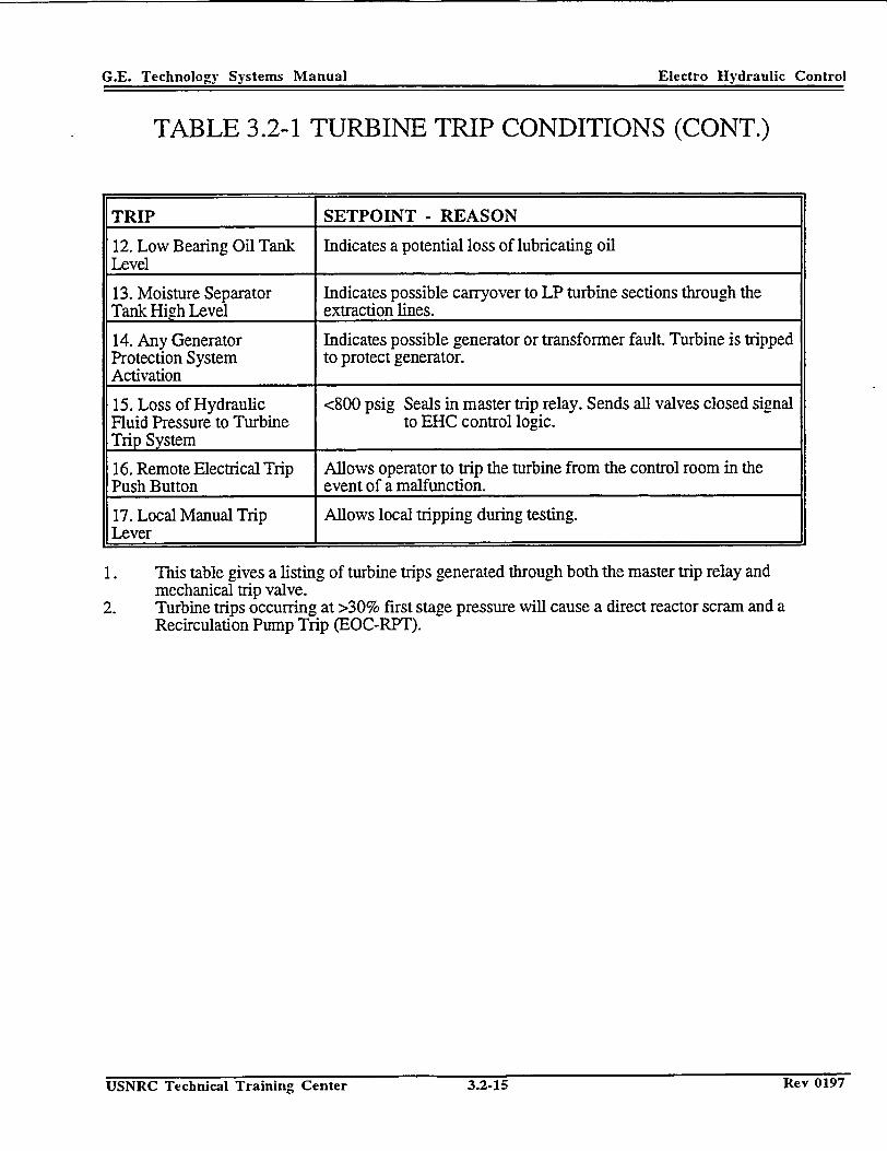
G.E. Technology Systems Manual Electro Hydraulic Control
TABLE 3.2-1 TURBINE TRIP CONDITIONS (CONT.)
This table gives a listing of turbine trips generated through both the master trip relay and mechanical trip valve. Turbine trips occurring at >30% first stage pressure will cause a direct reactor scram and a Recirculation Pump Trip (EOC-RPT).
USNRC Technical Training Center 3.2-15 Rev 0197
TRIP SETPOINT - REASON
12. Low Bearing Oil Tank Indicates a potential loss of lubricating oil Level
13. Moisture Separator Indicates possible carryover to LP turbine sections through the Tank High Level extraction lines.
14. Any Generator Indicates possible generator or transformer fault. Turbine is tripped Protection System to protect generator. Activation
15. Loss of Hydraulic <800 psig Seals in master trip relay. Sends all valves closed signal Fluid Pressure to Turbine to EHC control logic. Trip System
16. Remote Electrical Trip Allows operator to trip the turbine from the control room in the Push Button event of a malfunction.
17. Local Manual Trip Allows local tripping during testing. Lever
1.
2.
USNRC Technical Training Center 3.2-15
G.E. Technology Systems Manual Electro Hydraulic Control
Rev 0197

Speed Control Unit ----------------------------------- --------- 1
Acceleration Select P/B's
] /I Intercept ]
Valve Gain
Turbine 2.77°/JtRPM Speed
Select P/B's
Turbine Valve/Gain Speed ----------------
L ------ - - - - - - - - - - - - J
I- - - -
LoadLoa See -Malcer i • Selector
Loss of Stator [----r-' -- Cooling
SLoad Set I , SncSe Seld I Runback Ckt NoI eIpcted I
40% A
Load Rejecl Crossover Pressure Circuit L A,.^
I ..... Q I,.LdUI n'imll[J
Throttle Pressure
,l Closed Bn i ased - BIA ITSrtn T r1.1 n Flow
CWoCdntroTl
Preessure HV Gin'"'''aI. Demand
IAS -- -- Val-ve P ssureContrl Ui Ve C o U Demand Shotlea , ) (:. Small Close Bias•)'-' , Closed on Vcu
Throtessr - S, Cooldown T vawcuum PrsueBypass Jack' 0% <7' Hg ._
Pressure Control Unit Valve Control Unit
(D b.¢Figure 3.2-1 Electro Hydraulic Control System Logic
100%.Openlng Bias ,(+)
C.0
Ut
-1
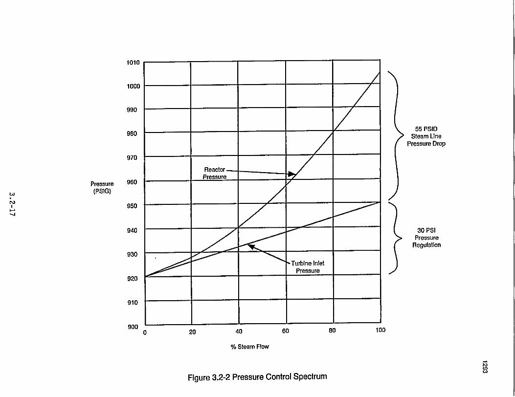
1010
1000
990
980
970
Pressure 960 (PSIG)
950
940
930
920
910
9000 20 40
% Steam Flow
60 80
55 PSID Steam Line
Pressure Drop
30 PSI Pressure
Regulation
100
C,)
Figure 3.2-2 Pressure Control Spectrum
G.E. Technology Systems Manual
Figure 3.2-3
(Later)
S.... . . . • . • • • • . i T) . wIIN',I
ev 1174USNRC Technical Training Center I

Front Stanu-.d Trip System Turbine Trip Oil (ETS)
Firgure 3.2-4 EHC System Hydraulic Power Unit
Actuating supply to -1 control and Intercept
valves (FASTC)
Actuating supply to turbine and Intermediate stop valves
and bypass valves (FAS)
"Pump )ecreasing)
EHC Oil Drains
0
CD

DRAINS
Figure 3.2-5 EHC Fluid Supplies
- - - - EMEROENCYTRIPSUPPLYS.... EMERGENCY TRIP SUPPLY IETS|
FLUID ACTUATOR SUPPLY WFAS)
- - - FLUID ACTUATOR SUPPLY TRIP CONTROL IFASTC)
..............- FLUID JET SUPPLY (FJSI
_. DRAINS

TRIP RESET OVERSPEED BUTTON BUTTON TRIP TEST
TO SPEED REFERENCE AND VALVE POSITIONING CIRCUITS
Figure 3.2-6 Emergency Trip System

5,
+
ACCELERATION INTEGRATOR
OUTPUT (VOLTS)
- I
5
To T1TIME -
_____________ I
RPM
To T1 T2 T3
TIM E---'-D
Figure 3.2-7 Turbine Roll
3.2-27
5
SPEED ERROR
SUMMING JUNCTION
OUTPUT (VOLTS)
5
1800
TURBINE RPM
0

Boiling Water Reactor GE BWRI4 Technology
Technology Manual
Chapter 3.3
Feedwater Control System

G.E. Technology Systems Manual Feedwater Control System
Table of Contents
3.3 FEEDWATER CONTROL SYSTEM ................................................................... 1
3.3.1 Introduction ......................................................................................... 1
3.3.2 Component Description ........................................................................... 2
3.3.2.1 Water Level Instrumentation ............................................................ 2
3.3.2.2 Steam Flow Instrumentation ............................................................ 2
3.3.2.3 Feedwater Flow Instrumentation ...................................................... 2
3.3.2.4 Steam Flow/Feed Flow Comparator ................................................. 3
3.3.2.5 Reactor Level/Flow Error Network .................................................... 3
3.3.2.6 Master Level Controller .................................................................. 3
3.3.2.7 Manual Auto Transfer Stations ......................................................... 4
3.3.2.8 Reactor Feed Pump Turbine Speed Controls ......................................... 4
3.3.2.9 Startup Level Controller ................................................................. 5
3.3.2.10 Setpoint Setdown ......................................................................... 5
3.3.3 System Features and Interfaces ................................................................... 5
3.3.3.1 Vessel Level Control During Plant Startup ............................................ 5
3.3.3.2 Loss of Steam or Feedwater Flow Signals ............................................. 6
3.3.3.3 Loss of Level Signal ..................................................................... 6
3.3.3.4 System Interfaces ......................................................................... 7
3.3.4 BWR Differences .................................................................................. 7
3.3.5 Summary ........................................................................................... 8
List of Figures
3.3-1 Basic Feedwater Control System ..................................................................... 9
3.3-2 Feedwater Control System .......................................................................... 11
3.3-3 Reactor Water Level Block Diagram ............................................................... 13
3.3-4 Steam Flow Block Diagram ........................................................................... 15
3.3-5 Feedwater Flow Block Diagram ..................................................................... 17
3.3-6 Feedwater Control System Controllers ............................................................ 19
*,--- A1fl�
USNRC Technical Training Center 3.3-i I�vv ULYI)3.3-i Rev U1.96USNRC Technical Training Center

G.E. Technology Systems Manual Feedwater Control System
Table of Contents
3.3 FEEDWATER CONTROL SYSTEM ................................................................... 1
3.3.1 Introduction ......................................................................................... 1
3.3.2 Component Description ......................................................................... 2
3.3.2.1 Water Level Instrumentation ........................................................... 2
3.3.2.2 Steam Flow Instrumentation ........................................................... 2
3.3.2.3 Feedwater Flow Instrumentation ..................................................... 2
3.3.2.4 Steam Flow/Feed Flow Comparator ................................................. 3
3.3.2.5 Reactor Level/Flow Error Network .................................................... 3
3.3.2.6 Master Level Controller ................................................................ 3
3.3.2.7 Manual Auto Transfer Stations ........................................................ 4
3.3.2.8 Reactor Feed Pump Turbine Speed Controls ......................................... 4
3.3.2.9 Startup Level Controller ................................................................ 5
3.3.2.10 Setpoint Setdown ......................................................................... 5
3.3.3 System Features and Interfaces ................................................................. 5
3.3.3.1 Vessel Level Control During Plant Startup ........................................... 5
3.3.3.2 Loss of Steam or Feedwater Flow Signals ........................................... 6
3.3.3.3 Loss of Level Signal ................................................................... 6
3.3.3.4 System Interfaces ........................................................................ 7
3.3.4 BWR Differences ................................................................................. 7
3.3.5 Summary ........................................................................................... 8
List of Figures 3.3-1 Basic Feedwater Control System .................................................................... 9
3.3-2 Feedwater Control System .......................................................................... 11
3.3-3 Reactor Water Level Block Diagram ................................................................. 13
3.3-4 Steam Flow Block Diagram ........................................................................ 15
3.3-5 Feedwater Flow Block Diagram ................................................................. 17
3.3-6 Feedwater Control System Controllers ............................................................ 19
U~N¶~. LUI.1 ii .2IIZ c. f, # 14 .A- Rev 0197USNRC itechnica, ra n ng en e.

G.E. Techno1o�y Systems Manual 'Feedwater Control System 3.3 FEEDWATER CONTROL
3.3 FEEDWATER CONTROL
SYSTEM
SLesson Objectives:
1. State the system's purpose. 2. Explain how the system accomplishes its
purpose. 3. List the parameters used by the system. 4. Explain the uses of the total steam flow, total
feedwater flow, and reactor vessel water level - signals.
5. Discuss the components controlled by the 71 system. :
6.- Discuss the modes of control used by the system: - I _
* 7. Explain how this system interfaces with the following systems:
* a. Reactor Vessel Instrumentation System b: Main Steam System c. Condensate and Feedwater System d. Recirculation System
"* e. Recirculation Flow Control System. Sf. Rod Worth Minimizer
-3.3.1 Introduction
The purposeof the Feedwater Control System (FWCS) is to control the rate of feedwater flow to the reactor vessel to maintain the proper vessel water level.
The functional classification of the FWCS is that of a power generation system.
The FWCS controls reactor water level low enough to minimize carryover, which is a condition in which moisture is entrained in, the steam leaving the reactor vessel. The FWCS controls reactor water level high enough to minimize carryunder which is a condition in which steam is entrained in the reactor vessel
annulus water pumped by the Recirculation System. If reactor -vessel water level -becomes abnormally low;,the core inlet subcooling also decreases, making reactor operation closer to thermal limits. ,
During normal reactor operation, the level of the water in the reactor is controlled by a feedwater controller which receives inputs from reactor vessel water level, steam mass'flow rate, and feedwater mass flow rate transmitters. The water level is measured by three independent sensing networks, each consisting -of. a differential pressure transmitter connected to a water reference condensing chamber leg located iri the drywell. Feedwater mass flow rate is measured by flow transmitters coupled across flow elements in the feedwater lines. Total feedwater mass flow rate, as used by this system, is the sum of the signals from the feedwater lines. Steam mass flow rate through each of the steam lines is measured by the differential pressure across the steam flow restrictors in each -steam line. The steam flow signals are summed before being used by the feedwater control circuit."
The Feedwater Control System, shown in -Figures 3.3-1 and 3.3-2, generates signals which
- regulate the opening of the turbine speed control steam supply valves, thereby controlling the pumping effort of the turbine driven reactor feed pumps.- The Feedwater Control -System -also generates a control signal that can regulate the opening of the startup .valves.
The rate of feedwater flow is thus controlled, maintaining the reactor water level at the desired level. During steady state operation, feedwater
, mass flow rate exactly matches steam mass flow rate and the water level is'maintained. A change in steam mass flow is immediately sensed, and the system adjusts the rate of feedwater flow to
USNRC Technical Training Center 3.3-1 Rev IJIY7/" Rev 01973-3-1
G.E. Technology systems Manual ,. "Feedwater 'Control -System
' -USNRC Technical Training Center
G.E.Tecnoloy Sstem MaualFeedwater Control Systemn
balance the two mass flow rates, maintaining normal water level. Reactor vessel water level, feedwater mass flow rate, and steam mass flow rates are recorded in the control room. Exceptionally high or low reactor vessel water levels are annunciated in the control room. The desired level in the reactor is constant over the range of 0 to 100% steam flow.
3.3.2 Component Description
The major components of the FWCS are discussed in the paragraphs which follow.
3.3.2.1 Water Level Instrumentation
Reactor vessel water level is measured by three independent, differential pressure transmitters. The transmitters are connected to a reference column located in the drywell and a reactor vessel instrumentation tap (Section 3.1). All three transmitters provide a narrow range level indication (0 to +60 inches above instrument zero). Figure 3.3-3 shows a block diagram of the reactor vessel water instrumentation.
All three level transmitters send signals to alarm units which then are arranged in a two-out-ofthree coincidence logic to generate a high water level turbine trip signal (+56.5").
The main turbine and both reactor feedwater pump turbines all trip upon conditions of high water level to prevent damage from moisture carryover.
Only the A or B level transmitter may be used in the Feedwater Control System's logic. The selection is made via the level selector switch. The selected level-signal is recorded on panel 603.,The selected level signal is also applied to two alarm units, a level analog input to the
computer, the level/flow error summer, the startup valve level controller and to the level control mode selector switch. One of the alarm units provide both high and low level annunciators, the other provides a low reactor vessel water level-feedwater pump interlock (operational limitor), in the Recirculation Flow Control System logic (Section 7.2).
3.3.2.2 Steam Flow Instrumentation
Steam flow is sensed as the differential pressure across the steam flow restrictor of each main steam line. The differential pressure signals are then sent through square root extractors to obtain four signals which are proportional to steam flow through the associated steam line. The individual steam line flows are then summed together to get the total steam flow signal. Figure 3.3-4 shows a block diagram of the steam flow instrumentation.
The total steam flow signal is sent to a control room recorder, to the steam flow vs. feed flow comparator, to a trip unit (which is associated with bypassing the Rod Worth Minimizer (RWM) System (Section 7.5) functions and displays), to the Nuclear Steam Supply Shutoff System (NSSSS), Section 4.4), and to the steam leak detection summer.
3.3.2.3 Feedwater Flow Instrumentation
Feedwater flow is measured by venturi flow elements located in the two feedwater inlet lines to the reactor vessel. The differential pressure signals are then- sent through square root extractors to obtain two signals which are proportional to feedwater flow throughthe associated feedwater line. The two individual line flows are then summed together to get the
USNRC Technical Training Center
L_
G.E., Technology Systems Manual
3.3-2 Rev 0197
I- Feedwater Control System
total feedwater flow signal. Figure 3.3-5 shows a
block diagram of the feedwater- flow
instrumentation.
The total feedwater flow signal is sent to a
* control room recorder, to the steam flow vs. feed
flow comparator, and to a trip unit. The trip unit
provides an interlock signal to the Recirculation % Flow Control (RFC) System (Section 7.2).
3.3.2.4 Steam Flow/Feed Flow. Comparator
The steam :flow summer output -(positive
algebraic sign) .and feedwater flow summer
output (negative algebraic sign) are sent to the
steam flow/feed, flowt comparator. Its. output
(flow error-) is biased such that when the steam flow and the feedwater flow are equal, the
amplifier output is at 50%. When the steam flow
exceeds the feedwater flow, the amplifier output
is greater than 50%; and when the feedwater flow exceeds the steam flow, the amplifier output
Sis less than 50%. The deviation of the amplifier
output from steady state 50% condition is
proportional to the rate of change of water
inventory' in the vessel. The flow error signal is
sent to the reactor level/flow error network,
where it is compared to the selected level signal.
-3.3,2.5 .Reactor Level/Flow Error Network
The algebraic signs within the reactor level/flow
error network are such that when steam flow t
6xeceeds feedwater flow, the output signal
S(referred to as the modified level signal) is less
Sthan the level signal, and the need for additional
feedwater flow is sensed. The reverse is true for
high feedwater flow. Thus, an anticipatory signal
- is obtained which corrects for projected changes
in level due to process flow changes.This
anticipatory signal then corrects feedwater flow to lessen the effect of changes on reactor level caused by a change in steam flow. During three
element control, the modified level signal .is provided as the'input to the master controller. The amount of ,level dominance within the Feedwater ýControl System-can be adjusted by changing the bias signals at the steam flow/feed flow comparator and the reactor level/flow error
-network. ,
-3.3.2.6 Master, Level Controller
-The master level controller is provided to control
feedwater flow -during normal reactor power
,operation. The master controller has a provision
for automatic as well as manual operation.
,In the automatic mode, the overall system mode
of operation (1 element or 3 element) is
determined by the level control mode switch. The
input signal .(actual level for, 1 element or
modified level for 3 element) is compared to a
level setpoint which is manually adjusted by the
operator. The resulting error signal is amplified
-and sent to the master controller output.
,In the manual mode the control error signal is
isolated and ,control is established by the use, of
manual open and close pushbuttons located on
the controller face.
In either case, the output of the master controller
,is routed via the individual reactor feed pump
turbine (RFPT) manual/auto (M/A) transfer
.'stations to function, generators. -The function
generators make the master controller output
signal linear with respect to each of the RFPT
characteristics. The signals are then sent to the
RFPT speed controls.
ID, Al0
•, USNRC Technical Training Center - 3-3-3
, , ir lir L I s -- Manual ec no ogy .7
- . I
G.E. Technology Systems Manual
The master level controller is shown in Figure 3.3-6. The front panel of the controller contains a vertical setpoint scale, a vertical setpoint deviation display, a vertical setpoint adjustment thumbwheel, a horizontal output' meter, manual/auto transfer pushbuttons with indicator lights to show the selected mode of operation, and manual open and close pushbuttons.
The vertical setpoint scale indicates the level setpoint chosen by the operator via the thumbwheel. The controller deviation meter indicates the difference between the level setpoint and the present input signal value. During normal operation the reactor- vessel level is maintained at its setpoint, and the meter indicates zero deviation (meter pointer centered). If the input value is below the setpoint, the deviation meter indicates below center; and if the input value is above the setpoint, the deviation meter indicates above center. The output meter indicates the controller output signal from 0 to 100%.
When in the automatic mode, the signal to the master controller can be'modified'by-a steam flow level program amplifier. This portion of the system is designed to modify the level setpoint so that the steady state level varies inversely with steam flow to reduce adveise affects of carryover and carryunder. This capability is not used.
3.3.2.7 Manual Auto Transfer Stations
The function of the two manual/auto (M/A) transfer stations is to provide a flow demand signal which is used to control the speed of the respective RFPT. Transfer pushbuttons on the controller allow the operator to select automatic of manual modes of operation. In the manual mode, a flow demand signal is generated within the controller by using the manual open and close pushbuttons on the controller. The manual mode
Feedwater Control System
provides the operator with the capability of independently controlling the speed of each RFPT. In the automatic mode, the controllers receive the flow demand signal from the master level controller. The manual/auto transfer station output is sent to the RFPT speed controls via a function generator.
The manual/auto controller is shown-in Figure 3.3-6. The front panel of the controller contains a vertical input meter, a horizontal output meter, manual/auto transfer pushbuttons with indicator lights to show the selected mode of operation, and manual open and close pushbuttons. The A RFPT controller has an additional vertical bias adjustment thumbwheel to allow adjustment of the A RFPT signal so that both RFPTs will have the same discharge pressure and therefore flow.
3.3.2.8 Reactor Feed Pump Turbine Speed Controls
Reactor feed pump turbine speed is controlled by positioning the steam admission valves for each RFPT based on signals developed by devices within the FWCS electronic circuitry. There are two devices, a motor gear unit (MGU) and a motor speed changer (MSC), which send RFPT speed demand signals to the RFPT steam admission valves via a low value selector. This low value selector constantly receives two separate input signals and passes only the one which is demanding the lowest RFPT speed (rpm).
The motor gear unit is tied directly to the FWCS electronic circuitry and is normally the device actually controlling RFPT speed. This unit can control the RFPT over the range of 1020 rpm, which is the MGU low speed stop (LSS), and 5950 rpm, which is the MGU high speed stop (HSS).
USNRC Technical Training Center 3.3-4 Rev 0197
I-
Rev 0197USNRC Technical Training Center 3.3-4

G.E. Technology Systems Manual FewtrCnrlSse
The motor speed changer is a manual device which can control the. RFPT over the range of 0
rpm, which is the MSC low, speed stop, and 5950 rpm, which is the MSC high speed stop.
The MSC is used to startup the RFPT and bring
Ait to the point that the MGU takes control The
MSC is then positioned to its high speed stop so that the MGUwill have control over its entire
speed range. The MSC can be used to control a *RFPT in the event of a FWCS circuitry failure.
Once a speed demand signal leaves the low value selector,' the RFPT steam admission valves are
positioned via a hydraulic oil and mechanical "-linkage network in order to regulate the -RFPT steam supply which allows RFPT speed control.
. 3.3.2.9 ,,Startup -Level Controller
-'-The startup'level controller is operated in the ,-,same fashion, as the master level controller
previously discussed in paragraphs 3.3.2.6. In 'the automatic mode, reactor vessel water level is
the input signal. The controller has a setpoint dial which allows, the operator to set the level he -wishes to maintain. Physically, the controller is
-identical to the master level controller. The controller output is sent to an electro/pneumatic (E/P) converter.
The E/P converter controls the air pressure to
startup valves 007X and 007Y. As the level in
the vessel decreases, the E/P converter receives a
signal from the startup level controller to increase
- the air pressure and open the valves. When level
reaches the setpoint, the controller output ,'decreases 'causing air pressure to - decrease
allowing spring pressure to modulate the valves to a new position. - 1 1
3.3.2.10 ,Setpoint Setdown
The Master Level Controller is equipped with a level setpoint setdown circuit. This circuit helps -prevent a high level trip of the feedwater turbines -following a scram.-A void collapse-due to the
power decrease within the vessel will result in a decreased level without any actual change in
Svessel inventory. To prevent unneeded inventory -replenishment by the feedwater system-under 'these circumstances, the setpoint setdown circuit
- automatically lowers the level setpoint to 18" on a
reactor scram; concurrent with a Level 3
(+12.5") signal, to maintain -an -essentially
constant inventory in the vessel. This prevents an excessively high vessel level when the core void content is re-established. - .
The decreased setpoint remains the level control circuit input until the setpoint setdown logic has
been reset by the manual reset pushbutton.
3.3;-3 -System Features and Interfaces
- A short *discussion of system:features and
- interfaces this system ý. has ,with other plant systems is discussed in the paragraphs which
follow. -
3.3.3.1 Vessel Level Control During Plant Startup
'During periods of plant shutdown, level control is accomplished by Control Rod Drive Hydraulic System flow input to the reactor vessel (Section 2.3) and reject flow from the Reactor Water Cleanup System (Section 2.8). Backup input is provided by the condensate and condensate booster pumps via the startup valve being controlled by the startup level controller.
USNRC Technical Training Center - 3.3-5 i'ev U3YI
S Feedwater -Control' System
Rev 0.393.3-5USNRC Technical Training Center

G.E.Tecnoloy Sstem MaualFeedwater Control System
During startup, the startup-valvies can function adequately to maintain vessel level below approximately -500 psig using the condensate and the condensate booster pumps. Above -600 psig these pumps do not have sufficient discharge head to inject into the reactor vessel so the reactor feedwater pumps must be used.
During operation at <500 psig the startup valves are initially controlled manually using the startup level controller to maintain reactor water level: As more steam is taken from the reactor vessel for auxiliary loads on startup, the startup valve control can be changed to the automatic mode on the startup level controller.
At -350 psig a reactor feedwater pump is warmed up and placed in service. Initial rollup of the RFPT is accomplished by, use of the motor speed changer. Once above 1020 RPM the RFPT control can be transferred to the motor gear unit. When the startup level control valves approach 80% open the RFPT speed wilPbe shifted to single element automatic control of the Master Controller Unit by placing the M/A transfer station to automatic and then the feedwater pump's discharge valve opened. At this time the startup level controller can be changed to the manual mode of operation and the startup valves closed.
When feedwater flow to the reactor vessel is approximately 25% the 1 or 3 element mode selector switch can be moved: to 3 element control.
3.3.3.2 Loss of Steam or Feedwater Flow Signals
The single element automatic control mode provides an alternative to the three element automatic control mode in case of a failure or
malfunction in the feedwater/steam flow part of the control system. During this mode of operation, the master controller and both of the manual/auto trarisfei" stations are in the automatic position. The level signal selector switch is in the single element position. The level signal from the selected level sensor is compared to the desired level at the master level controller, and an automatic signal is sent to control the speed of the feed pump turbine. This mode of control is less responsive to changes in the water level because the anticipatory response provided by the steam/feed flow error signal is not available.
Loss of one feedwater flow signal at high power (3 element control), if not noticed and corrected, results in a high reactor water level turbine trip and resulting scram.' This loss of signal is treated as if the steam flow rate had not changed. This is true, but the indicated feedwater flow rate is' cut in half. The Feedwater Control System tries to increase feedwater flow to compensate for the feed flow/ steam flow mismatch. As level increases because of this excessive feedwater flow, the signal to be RFPT's decreases; and if allowed, level would stabilize out at some higher reactor water level at 100% steam and feedwater flow, but this level is normally above the high level turbine trip setpoint.
Loss of one steam line flow signal at 100% power causes the total steam flow signal, determined by the FWCS to decrease to 75%. This decrease is compensated for by the FWCS by decreasing feedwater flow. As level decreases, the feed/ steam flow error is eventually compensated for at a lower reactor water level. Below this lower level, feedwater flow again increases to compensate for decreasing level. Eventually, the reactor plant stabilizes at a lower reactor vessel level and 100% steam and feedwater flow.
U�P�KL iecnnicai [raining Center 3.3-6 Rev 03973.3-6 Rev 0397
G.E. , Technology -Systems Manual
uSINRCu lechnical Training Center

SFeedwater Control SystemGx.E.. I eL1IIIoJIUj yaýA
-. A total loss of steam flow signal causes a reactor
-,scram on low reactor water level if left
unchecked.
3.3.3.3 Loss of Level Signal %
If the C level- signal fails either upscale 'or
downscale, there is no real effect on the FWCS.
-If the A or -B level signal fails upscale- or
-*downscale, there can be either no effect or quite a
- large effect on the FWCS depending on whether
or not the level signal which failed was selected
for control. If the failed level signal was not
selected for control, there is no real effect on the
FWCS.
If the level signal (A or B) selected for control
fails upscale, the FWCS responds as if reactor
water level were truly very high and decreases
the RFPT speed tominimum. This results in
substantially less feedwater flow than is required
to match the existing steam flow and causes
reactor water level to decrease rapidly to the low
level setpoint, at which point the reactor scrams
to terminate the event.
-If the level signal (A or B) selected for control
"fails downscale, the FWCS responds as if reactor
water level were truly very low and increases the
RFPT speed to maximum. This results in
substantially more feedwater flow than is
required to match 'the existing steam flow and
, causes reactor water level to increase rapidly to
the high level turbine trip setpoint.
In either case of failure, once the FWCS starts
responding, a steam flow/feedwater flow
mismatch is created. This mismatch tends to
resist the action the FWCS is taking but the flow
mismatch cannot overcome the level error
associated with a failed level signal since the
FWCS is a level dominant system.
3.3.3.4 System Interfaces
A short discussion of interfaces this system has
with other plant systems is giyen -in the
paragraphs which follow.
Main Steam System (Section 2.5)
The Main Steam System steam flow restrictors
provide the steam flow input to the FWCS. The
main turbine receives a trip signal from the
FWCS.
.Condensate and Feedwater System •
(Section 2.6) .
The feedwater flow elements provide the
feedwater flow input to the FWCS. The FWCS
controls the speed of the RFPT's, the position of
the startup valve, and provides a trip signal to the
RFPT's. "
Reactor Vessel Instrumentation System
(Section 23.1) K
The Reactor Vessel Instrumentation -System
provides reactor yessel water level inputs to the
FWCS.
Rod Worth Minimizer _System (Section
7.5)
The;FWCS total steam flow signal is used to
automatically bypass the Rod Worthý Minimizer
(RWM) System functions at higher power levels.
The EWCS total steam flow signal is also used to
control the RWM, System displays :at the low
power alarm point.-
S. . . . ... -• .. . .. .Rev 0197USNRC Technical Training Center Rev 01970.0-1
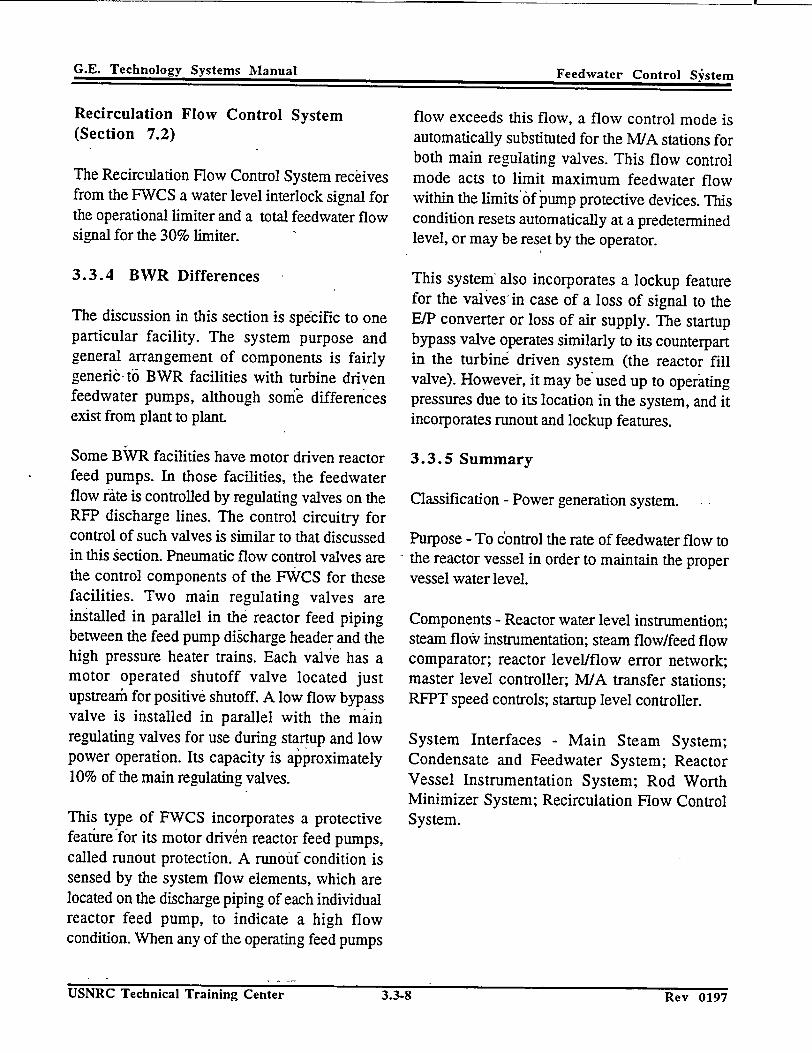
- I -__________
G.E. Technology Systems Mlanual
Recirculation Flow Control System (Section 7.2)
The Recirculation Flow Control System receives from the FWCS a water level interlock signal for the operational limiter and a total feedwater flow signal for the 30% limiter.
3.3.4 BWR Differences
The discussion in this section is specific to one particular facility. The system purpose and general arrangement of components is fairly generic -t6 BWR facilities with turbine driven feedwater pumps, although sonfe differences exist from plant to plant.
Some BWR facilities have motor driven reactor feed pumps. In those facilities, the feedwater flow rate is controlled by regulating valves on the REP discharge lines. The control circuitry for control of such valves is similar to that discussed in this section. Pneumatic flow control valves are the control components of the FWCS for these facilities. Two main regulating valves are installed in parallel in the reactor feed piping between the feed pump dikcharge header and the high pressure heater trains. Each valve has a motor operated shutoff valve located just upstrearil for positive' shutoff. A low flow bypass valve is installed in parallel with the main regulating valves for use during startup and low power operation. Its capacity is ap proximately 10% of the main regulating valves.
This type of FWCS incorporates a protective feature -for its motor driven reactor feed pumps, called runout protection. A runouf condition is sensed by the system flow elements, which are located on the discharge piping of each individual reactor feed pump, to indicate a high flow condition. When any of the operating feed pumps
flow exceeds this flow, a flow control mode is automatically substituted for the MIA stations for both main regaulatingg valves. This flow control mode acts to limit maximum feedwater flow within the limitso6f pump protective devices. This condition resets automatically at a predetermined level, or may be reset by the operator.
This system'also incorporates a lockup feature for the valves, in case of a loss of signal to the E/P converter or loss of air supply. The startup bypass valve operates similarly to its counterpart in the turbine driven system (the reactor fill valve). However, it may be used up to operiating pressures due to its location in the system, and it incorporates runout and lockup features.
3.3.5 Summary
Classification - Power generation system.
Purpose - To control the rate of feedwater flow to the reactor vessel in order to maintain the proper vessel water level.
Components - Reactor water level instrumention; steam flowv instrumentation; steam flow/feed flow comparator; reactor level/flow error network; master level controller; MIA transfer stations; RFPT speed controls; startup level controller.
System Interfaces - Main Steam System; Condensate and Feedwater System; Reactor Vessel Instrumentation System; Rod Worth Minimizer System; Recirculation Flow Control System.
u�r�K A... I ecnnicai I raining Lenter Rev 0197Rev 0197
1. 011 10 SLem P..A ý# 1- .1 1 C!.*.
USNRC lechnical Iraining t;enter 3.3-8

!-- - lot-2
Typical of 2 Typicl of 4 T
RFP )Y
rTuirbin~e.
Startup Level]
Controller5
Governing System
I I v
Function Steam FIowvs.
GenraorFeed Flow Comparato
A B
I I
Etautiontr
To Other nin I E e
Level/Flow
" "tMaster Level Auto Setpotnt l. eeEementErrSme Manual Input Conroe Setdown Logic ýTr Ero Sme
Figure 3.3-1 Basic Feedwater Control Systm

Level Selector
Rx Level "A"
Rx Level "B"
Rx Level "C"Lel4 Level 4
Turbine Firs ULT. p I Stage Pressu
HighLevel TurblneTnp (2/3)
Level 8 Steam Le: Detecttoi
LevelAmplfier50% Bias
S~Level 7
S lrm •A. & 3Unit Three Sini
3-Ho Level 4 Element Elery Water Level
ire
Steam Fl•J'mr ,
Flow"A" I
Steam Fl
Flow"" L_•Total Steam
J Flow t toam ISummer Flow"C"
Steam Sem FI
Feed Flc
Flow"D)" Compara
Fl Feedwater
Flow "A" Total Feed
Flow Summer
Feedwater Flow "B"
Turb Steam
Flow Rec
30 Sec Alarm
DulTi 20% & Ut30% RWM
--- Computer
Amplifier(*
W ,
•te
5%Bias
-Flow
rip To RFCS 30% speedlim i ( <(@ <20% feedflow)
nle ient
\0Level Control Mode Switch
Master LevelController
j I Reactor Setpoint Setdown Protectionr Logic & Reset System
Pushbutton
Setpoint Adjustment
W)(+) Tapes
A
Summer 0
"6A (D Transfer Tootl Station Feed P
Function GeneratorCoto
Failure
125VDC 120VAC -W 12595 p 1020-5950
ISteam Iubn
Trine rbn
niter, [' 5
Startup Level Controller
W Setpoint Adjustment
A Q Tapes
E
0/
S S
Startup lves
007Y 007X ( spring closed )
C -r C,
Figure 3.3-2 Feedwater Control System
leCIQSJ DOME 1=121. 62121 !.21WUSal
I
her
=ump

CR
High/Lc Alarm U
Compute
Contro
Level/Fl (Error Network
Level A A , LevelB A P/, Level C
PROP PROP ]AMP AMP
High Level Turbine Trip (2 of 3 rip 0U coincidence) 0
Unit~ Unit f1nit
I _I _ _ I
CR~ CR~
Level B Level C
A B
C R S!elector Switch
nit 0 Trip Trip 0 Input to RFC
Unit Unit Operational Limiter
Rx Vessel Water Level
vel Narrow & Upset I IRx. Water Level
low 3 Level Control Mode Switch Summer) CR (1 or 3 element control)
Steam/Feed Flow Error Conter
Controller
Figure 3.3-3 Reactor Water Level Block Diagram
3.3-13
1094

0594
Main Steam Une Flow Restrictors
Steam Row/Feed Flow Error Signal to Level/Flow Summer
Steam Rx. Total Feedwater Flow Pressure Flow
Figure 3.3-4 Steam Flow Block Diagram
3.3-15

1294
B Feedwater Flow
Nozzles
Proce r Compu
II Flow •ss Indicator uter [ A CR
Trip Unit
Input to RFC Minimum
LO~ Speed Umiter
Steam Flow/Feed Flow Error Signal to Level/Flow Summer
Total Steam Flow
Figure 3.3-5 Feedwater Flow Block Diagram
3.3-17
Flow Indicator Process
Compute
CR (-)
Feed Flow/ Steam Flow

III1 I 111111111i II 11111 S 20 40 60 80o 10O
0Cose I \÷ ÷
Manual/Auto Transfer Station
Figure 3.3-6 Feedwater Control System Controllers
0594
-45
-40
-35
-- 30
-100
- 80
- 60
-40
- 20
-o
C�e 0I Io0e j
* 0
Master Level Controller