Embed Size (px)
Citation preview

2-PASS SCOTCH MARINE DESIGNwith Wetback Construction
HIGH PRESSURE BOILERCapacities From 20 to 2500 BHP.
670 to 83,688 MBTU/HR.Up to 86,250 PPH Steam.
SKID MOUNTEDMODULAR PACKAGED
SERIES 250W
BOILER & WELDING CO., INC.
Section I & Section IV
150 PSI. Higher Pressures
Upon Request
HOT WATER
STEAMShown withSTACKMASTER Option
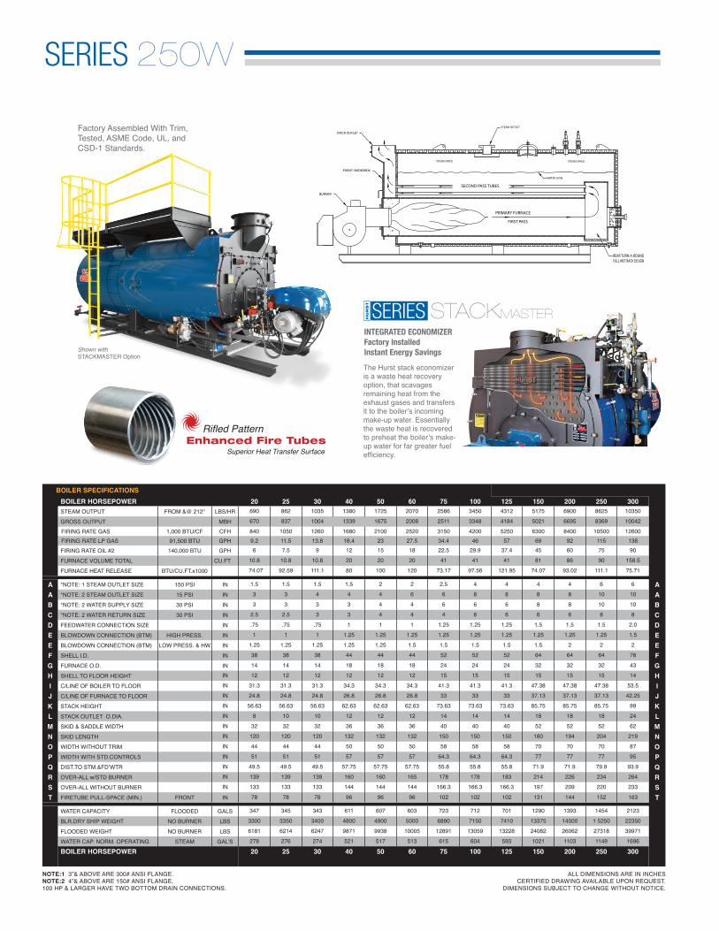
NOTE:1 3”& ABOVE ARE 300# ANSI FLANGE.NOTE:2 4”& ABOVE ARE 150# ANSI FLANGE.100 HP & LARGER HAVE TWO BOTTOM DRAIN CONNECTIONS.
SEMI WET BACK
ALL DIMENSIONS ARE IN INCHES CERTIFIED DRAWING AVAILABLE UPON REQUEST.
DIMENSIONS SUBJECT TO CHANGE WITHOUT NOTICE.
SERIES 250W
FRONT SMOKEBOX
BURNER
STACK OUTLET
PRIMARY FURNACE
SECOND PASS TUBES
RIGHT SIDE SECTION VIEW
FIRST PASS
FULL WET BACK DESIGNREAR TURN-A-ROUND
WATER LEVEL
STEAM SPACE STEAM SPACE
STEAM OUTLET
SERIES STACKMASTERINTEGRATED ECONOMIZERFactory InstalledInstant Energy SavingsShown with
STACKMASTER Option
The Hurst stack economizer is a waste heat recovery option, that scavages remaining heat from the exhaust gases and transfers it to the boiler’s incoming make-up water. Essentially the waste heat is recovered to preheat the boiler’s make-up water for far greater fuel efficiency.
BOILER SPECIFICATIONS BOILER HORSEPOWER 20 25 30 40 50 60 75 100 125 150 200 250 300STEAM OUTPUT FROM &@ 212° LBS/HR 690 862 1035 1380 1725 2070 2586 3450 4312 5175 6900 8625 10350
GROSS OUTPUT MBH 670 837 1004 1339 1675 2008 2511 3348 4184 5021 6695 8369 10042
FIRING RATE GAS 1,000 BTU/CF CFH 840 1050 1260 1680 2100 2520 3150 4200 5250 6300 8400 10500 12600 FIRING RATE LP GAS 91,500 BTU GPH 9.2 11.5 13.8 18.4 23 27.5 34.4 46 57 69 92 115 138FIRING RATE OIL #2 140,000 BTU GPH 6 7.5 9 12 15 18 22.5 29.9 37.4 45 60 75 90
FURNACE VOLUME TOTAL CU.FT 10.8 10.8 10.8 20 20 20 41 41 41 81 86 90 158.5
FURNACE HEAT RELEASE BTU/CU.FT.x1000 74.07 92.59 111.1 80 100 120 73.17 97.56 121.95 74.07 93.02 111.1 75.71
A *NOTE: 1 STEAM OUTLET SIZE 150 PSI IN 1.5 1.5 1.5 1.5 2 2 2.5 4 4 4 4 6 6 AA *NOTE: 2 STEAM OUTLET SIZE 15 PSI IN 3 3 4 4 4 6 6 8 8 8 8 10 10 AB *NOTE: 2 WATER SUPPLY SIZE 30 PSI IN 3 3 3 3 4 4 6 6 6 8 8 10 10 BC *NOTE: 2 WATER RETURN SIZE 30 PSI IN 2.5 2.5 3 3 4 4 4 6 6 6 6 8 8 CD FEEDWATER CONNECTION SIZE IN .75 .75 .75 1 1 1 1.25 1.25 1.25 1.5 1.5 1.5 2.0 DE BLOWDOWN CONNECTION (BTM) HIGH PRESS. IN 1 1 1 1.25 1.25 1.25 1.25 1.25 1.25 1.25 1.25 1.25 1.5 EE BLOWDOWN CONNECTION (BTM) LOW PRESS. & HW IN 1.25 1.25 1.25 1.25 1.25 1.5 1.5 1.5 1.5 1.5 2 2 2 EF SHELL I.D. IN 38 38 38 44 44 44 52 52 52 64 64 64 78 FG FURNACE O.D. IN 14 14 14 18 18 18 24 24 24 32 32 32 43 GH SHELL TO FLOOR HEIGHT IN 12 12 12 12 12 12 15 15 15 15 15 15 14 HI C/LINE OF BOILER TO FLOOR IN 31.3 31.3 31.3 34.3 34.3 34.3 41.3 41.3 41.3 47.38 47.38 47.38 53.5 IJ C/LINE OF FURNACE TO FLOOR IN 24.8 24.8 24.8 26.8 26.8 26.8 33 33 33 37.13 37.13 37.13 42.25 JK STACK HEIGHT IN 56.63 56.63 56.63 62.63 62.63 62.63 73.63 73.63 73.63 85.75 85.75 85.75 99 KL STACK OUTLET O.DIA. IN 8 10 10 12 12 12 14 14 14 18 18 18 24 LM SKID & SADDLE WIDTH IN 32 32 32 36 36 36 40 40 40 52 52 52 62 MN SKID LENGTH IN 120 120 120 132 132 132 150 150 150 180 194 204 219 NO WIDTH WITHOUT TRIM IN 44 44 44 50 50 50 58 58 58 70 70 70 87 OP WIDTH WITH STD.CONTROLS IN 51 51 51 57 57 57 64.3 64.3 64.3 77 77 77 95 PQ DIST.TO STM.&FD’WTR IN 49.5 49.5 49.5 57.75 57.75 57.75 55.8 55.8 55.8 71.9 71.9 79.9 93.9 QR OVER-ALL w/STD BURNER IN 139 139 139 160 160 165 178 178 183 214 226 234 264 RS OVER-ALL WITHOUT BURNER IN 133 133 133 144 144 144 166.3 166.3 166.3 197 209 220 233 ST FIRETUBE PULL-SPACE (MIN.) FRONT IN 78 78 78 96 96 96 102 102 102 131 144 152 163 T
WATER CAPACITY FLOODED GALS 347 345 343 611 607 603 723 712 701 1290 1393 1454 2123
BLR.DRY SHIP WEIGHT NO BURNER LBS 3300 3350 3400 4800 4900 5000 6890 7150 7410 13375 14500 1 5250 22350
FLOODED WEIGHT NO BURNER LBS 6181 6214 6247 9871 9938 10005 12891 13059 13228 24082 26062 27318 39971
WATER CAP. NORM. OPERATING STEAM GAL’S 278 276 274 521 517 513 615 604 593 1021 1103 1149 1696
BOILER HORSEPOWER 20 25 30 40 50 60 75 100 125 150 200 250 300
Factory Assembled With Trim,Tested, ASME Code, UL, andCSD-1 Standards.
Enhanced Fire TubesSuperior Heat Transfer Surface
Rifled Pattern

ALL DIMENSIONS ARE IN INCHES CERTIFIED DRAWING AVAILABLE UPON REQUEST.
DIMENSIONS SUBJECT TO CHANGE WITHOUT NOTICE.
** CONSULT FACTORY FOR BURNER SPEC’S75 HP & LARGER HAS 12” X 16” MANWAY 20-60 HP HAVE 3X4 HAND HOLES IN SHELL
350 400 500 600 700 800 900 1000 1100 1200 1300 1400 1500 1600 1800 2000 2250 250012075 13800 17250 20700 24150 27600 31050 34500 37950 41400 44850 48300 51750 55200 62100 69000 77625 86250
11716 13390 16738 20085 23432 26780 30128 33475 36823 40170 43518 46865 50215 53560 60255 66950 75319 83688
14700 16800 21000 25200 29400 33600 37800 42000 46200 50400 54600 58800 63000 67200 75600 84000 94500 105000160 184 230 275 320 368 413 460 506 550 598 644 688 734 826 918 1033 1148105 120 150 180 210 240 270 300 330 360 390 420 450 480 540 600 675 750
165 172 210 226 242 255 274 294 334 344 354 365 462 471 490 509 584 639
84.85 93.02 95.24 106.2 115.7 125.5 131.38 136.05 131.74 139.53 146.89 153.42 129.87 135.88 146.94 157.17 154.11 156.49
A 6 6 6 8 8 8 10 10 10 10 10 10 12 12 12 12 14 14 AA 10 10 10 12 12 12 14 14 14 14 14 14 14 14 14 16 16 16 AB 10 10 10 12 12 12 12 12 14 14 14 14 14 14 14 16 16 16 BC 8 8 8 10 10 10 12 12 12 14 14 14 14 14 14 16 16 16 CD 2.0 2.0 2.0 2.0 2.5 2.5 2.5 2.5 2.5 2.5 2.5 2.5 2.5 2.5 2.5 2.5 2.5 2.5 DE 1.5 1.5 1.5 2 2 2 2 2 2 2 2 2 2 2 2 2 2 2 EE 2 2 2 2 2 2 2 2 2 2 2 2 2 2 2 2 2 2 EF 78 78 84 84 90 90 96 96 106 106 106 106 120 120 120 120 130 130 FG 43 43 48 48 50 50 52 52 56 56 56 56 62 62 62 62 66 66 GH 14 14 15 15 16 16 16 16 16 16 16 16 16 16 16 16 16 16 HI 53.5 53.5 57.5 57.5 61.5 61.5 64.5 64.5 69.5 69.5 69.5 69.5 76.63 76.63 76.63 76.63 81.75 81.75 IJ 42.25 42.25 45.25 45.25 47.5 47.5 48.75 48.75 50.75 50.75 50.75 50.75 54.38 54.38 54.38 54.38 57.88 57.88 JK 99 99 106 106 113 113 119 119 129 129 129 129 144.25 144.25 144.25 144.25 154.38 154.38 KL 24 24 26 28 28 28 32 32 36 36 36 36 40 40 40 40 48 48 LM 62 62 66 66 72 72 80 80 88 88 88 88 102 102 102 102 108 108 MN 226 236 242 258 260 272 266 284 282 290 298 306 312 318 330 342 354 384 NO 87 87 92 92 100 100 104 104 114 114 114 114 129 129 129 129 137 137 OP 95 95 98 98 106 106 112 112 121 121 121 121 139 139 139 139 152 152 PQ 82.9 90.9 98.9 98.9 105 111 110 110 120 120 126 126 141 141 147 153 145 157 QR 268 277 280 296 294 306 308 326 ** ** ** ** ** ** ** ** ** ** RS 242 252 258 280 277 289 283 301 299 307 315 323 330 335 347 359 372 402 ST 172 181 178 194 194 206 201 219 216 224 232 240 244 250 262 274 275 306 T
2237 2352 2258 2785 3343 3517 3911 4258 5225 5413 5572 5765 7185 7366 7813 8091 9449 10516
23200 24100 27500 28950 32100 33500 38400 40350 44900 46250 47600 48950 70050 71400 74100 76900 94700 103000
42514 43622 48731 52065 59847 62691 70861 75691 88267 91178 93848 96800 129686 132538 138948 144055 173127 190283
1788 1882 1999 2179 2393 2512 2915 3178 3556 3685 3785 3919 5174 5307 5657 5839 6724 7497
350 400 500 600 700 800 900 1000 1100 1200 1300 1400 1500 1600 1800 2000 2250 2500
Pressure Designs Steam:20-2500 HP. - 150 PSI Higher pressuresupon request.
Pressure Designs Hot Water: 30-160 max psi.High pressure, high temperature Section I hot waterboilers available.
Boiler Design:2-Pass “Scotch Marine”Firetube design with stress relieving “Wetback” construction.

WET BACK ADVANTAGE
Dry backs boilers are subject to deteriorating rear refractory, leaking baffles, leaking door seals, and often found with a heat-stressed rear tube sheet . Fragile refractory baffling and door seals will require continuous monitoring, maintenance, and replace-ment, costing thousands of dollars in materials and specialized labor costs over the life of the boiler. In addition, broken baffles and leaking seals will short-circuit the boiler’s gas flow, causing high stack temperatures and lowering efficiency until repairs can be made. This can bring your production process to a costly halt.
Standard Steam Trim Operating & high limit pressure control.Modulating pressure control.Water column with gauge glass, combination low water cut-off & pump control. Probe Aux, L.W.C.O. w/ Manual Reset.Steam pressure gauge, syphon & test cock.Stack Thermometer, Watercolumn drain valve.Safety relief valve(s) per ASME Code.
Standard Water Trim
Operating & high limit tempera-ture control.Modulating temperature control.Probe type low water cut-off control w/ Manual Reset.Combination pressure & tem-perature gauge.Hot water return baffle for shock resistance.Safety relief valve(s) per ASME Code.Stack Thermometer.
50YEARS
HBC-0954109/2017
2- PASSWater CooledTURN-A-ROUND
SERIES 250W
Integration has become essential for efficient oper-ation and shared duty load. Hurst developed and offers a full line of processor based smart controls fully compatible with all Hurst designs including alterna-tive fuel models.Precise control of fuel and combustion air can result in very high efficiencies. Hurst intelligence control systems allow you to har-ness these savings while increasing overall boiler plant productivity.
INTEGRATED CONTROL SYSTEM
m o r e s o l u t i o n s
All of those frustrating problems have been designed out of the Hurst Series 250W Wet back. It has a full wet back radiant heat transfer area that promotes superior internal water circulation and rapid heat absorption. The 250W’s 2-pass design allows the fire tubes to expand and contract at its own rate without tube-to-sheet stress. All fire tubes are mechanically rolled, flared and beaded, making any tube service a simple matter. The only rear re-fractory in this design is a manway plug which allows ac-cess to the furnace for service and annual in-spection.