Embed Size (px)
Citation preview
BO
ILE
R S
ER
VIC
E IN
STR
UC
TIO
NS
MA
NU
AL
FPWALL HUNG GAS BOILER FORCENTRAL HEATING SUPPLY
Please Read Instructions CarefullySave for Future Reference
Do not store or use gasoline or other flammable vapors and liquids in the vicinity of this or any other appliance.
WHAT TO DO IF YOU SMELL GAS Do not try to light any appliance. Do not touch any electric switch; do not use any phone in your building. Immediately call your gas supplier from a neighbors phone. Follow the gas suppliers instructions. If you can not reach your gas supplier call the fire department.
Installation and service must be performed by a qualified installer, service agency or the gas supplier.
WARNING: If the information in this manual is notfollowed exactly, a fire or explosion may result causingproperty damage, personal injury or loss of life.
Manufactured by:
Biasi S.p.A.Verona, Italy
Distributed By:
Quincy Hydronic Technologies, Inc. Portsmouth, NH 03801
Phone: 603-334-6400Fax: 603-334-6401
RIVA FP SERVICE MANUAL - REV A
*17562.0187.0*17562.0187.0 0406 (49A4)USA

___________________________________________________________________________________________________
First Part Service Manual_______________________________________________________________
RIVA FP SERVICE MANUAL REV A 3
1 The Technical Manual
The aim of this manual is to provide technicalassistance operators with all the informationnecessary to facilitate maintenance of Biasiproducts.
To use this manual in the best possible wayand to find the information in it quickly it isnecessary to understand how it is laid out byreading the following carefully:
2 Manual layout
The manual is divided into three different parts(fig. 1).
The first part contains the general instructionson how to use and consult the manual; thenomenclature of the models illustrated in thismanual and the grouping criteria for eachfamily.
The second part contains booklets withtechnical data, hydraulic and wiring diagrams,troubleshooting instructions and start-upchecks, grouped into product families.
The third part contains the technical datasheets relative to each component, its basiccharacteristics, checking its condition andreplacing and/or servicing.
fig. 1
Parts two and three are preceded by an indexthat gives the contents and their order ofarrangement.
3 Topic, numbering, edition
The topic dealt with on each card is also shownin the top right corner of each page, the part inthe top left corner The pages are numbered inthe bottom corner (fig. 2).
Technical sheet edition date (month and year)is given between the Part and the Argument ontop of the page.
fig. 2Part one is laid out with consecutive numbers(fig. 3).
1 3 5
fig. 3Part two is arranged on two levels (fig. 4). Thefirst gives the acronym of the family to whichthe technical sheet belongs; the number thatfollows indicates technical sheet ordersequence inside each family.
M130.30CR - 7M130.30CR - 5M130.30CR - 3M130.30CR - 1
first levelsecond level
fig. 4Part three is also arranged on two levels (fig.5); the first is a number assigned to eachcomponent, the second indicates technical

___________________________________________________________________________________________________
First Part Service Manual_______________________________________________________________
RIVA FP SERVICE MANUAL REV A 4
sheet order sequence. Correspondencebetween component and number is given in theindex at the beginning of part three.
1-1 1-3 2-1 2-3
fig. 5
4 Updating
The evolution of Biasi products entails updatingthe technical assistance personnel and relativedocumentation.The updated documentation which will be sentto the Assistance Service Centres, whether inthe shape of a circular or technical sheets to beadded to the manual or to replace others, mustbe properly inserted.All technical service personnel must beinformed immediately of their contents.
5 Models
All models of products manufactured areidentified with a name. This name (from herereferred to as model) is determined by the unitconstruction characteristics (fig. 6)
M130.30CM
Max useful power in c.h.
30 = 30,00 kW (25 800 kcal/h)
C = Sealed Chamber
Boiler series
Combi Only
fig. 6
The information contained in this manual isapplicable to the following models:
M130.30CM
6 Serial number
Each unit has its own serial number, themeaning of which is given in fig. 7.
N210250205
Progressive number
Gas Type
N = NaturalG = L.P.G.
Construction month and year
fig. 7
7 Series
The boilers are grouped into families in part twoof this manual, each group including modelswith identical construction features and, hence,with identical maintenance.
Within each family the models differ only in theirnominal thermal capacity or othercharacteristics that do not call for differentmaintenance.
Series Models
M130------------------|M130.30CM

___________________________________________________________________________________________________
Second Part M130.30CM Maintenance Characteristic Verification_______________________________________________________________
RIVA FP SERVICE MANUAL REV A
Summary
Page
OVERALL VIEWM130.30CM - 1HYDRAULIC DIAGRAM..M130.30CM - 1ELECTRICAL DIAGRAM.M130.30CM - 2GAS ADJUSTMENT DATA.M130.30CM - 3FAULT FINDINGM130.30CM - 4CIRCUIT VOLTAGES...M130.30CM - 5OPERATION LIGHTS...M130.30CM - 6START UP CHECKS.M130.30CM - 6GAS CONVERSION..M130.30CM - 7
___________________________________________________________________________________________________
Second Part M130.30CM Maintenance Characteristic Verification_______________________________________________________________
RIVA FP SERVICE MANUAL REV A
___________________________________________________________________________________________________
Second Part M130.30CM Maintenance Characteristic Verification_______________________________________________________________
RIVA FP SERVICE MANUAL REV A M130.30CM - 1
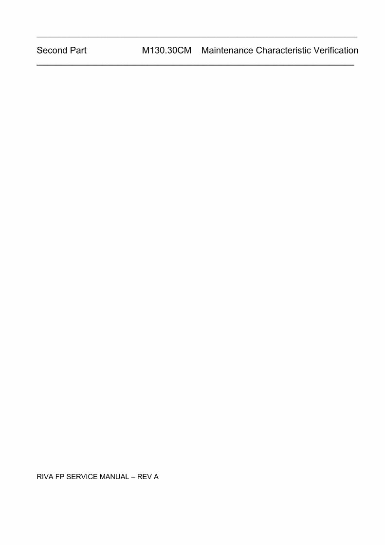
1 Overall View
Pump
Pump vent plug
Automatic air purger valve
Modulation gas valve
Flame-detecting electrode
Ignition electrodes
Burner Combustion chamber
Primary heat exchanger
Air pressure switch
Air pressure switch test points
Fan
C.h. PRV
Modulation operator
Safety thermostat
Control panel
C.h. temp. probe NTC
Gas valve inlet pressure test point
Gas valve outlet pressure test point
Primary circuit flow switch
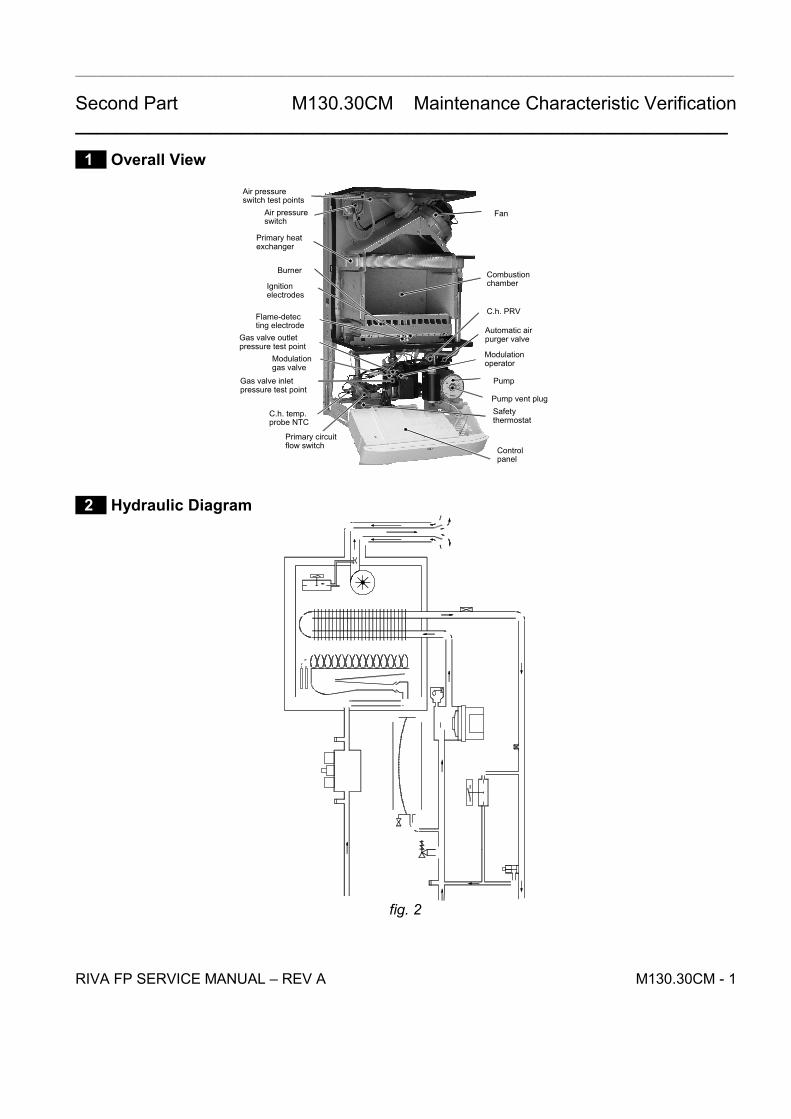
2 Hydraulic Diagram
fig. 2
___________________________________________________________________________________________________
Second Part M130.30CM Maintenance Characteristic Verification_______________________________________________________________
RIVA FP SERVICE MANUAL REV A M130.30CM - 2
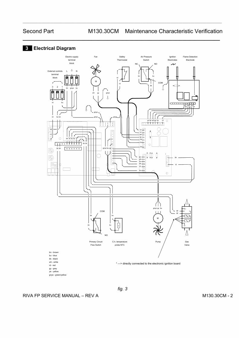
3 Electrical Diagram
ye bk wh gy bu rd
bk gy
gygy
M
~
t
probe NTCC.h. temperature
COM
NO
M
~COM
NONC
123 bk
bubn
rd
rd
gnyegywh
bu
rdbkbuwh
gybugnye
bk bk
gygnye bu
bk
bk
bubu
bu
bu
rdbk
gygy
L N
rd bu bn gnye gnye
gnye bubn
burd
gnye
Flow SwitchPrimary Circuit Pump
ValveGas
External controlsterminal
block
Electric supplyterminal
block
Fan SafetyThermostat
Air PressureSwitch
IgnitionElectrodes
Flame DetectionElectrode
bn - brownbu - bluebk - blackwh - whiterd - redgy - greyye - yellow
gnye - green/yellow
whgy
rdrd
bk
bu
bn
gy
ye wh bu rd
1
bk
rd
*
* ---> directly connected to the electronic ignition board
fig. 3
___________________________________________________________________________________________________
Second Part M130.30CM Maintenance Characteristic Verification_______________________________________________________________
RIVA FP SERVICE MANUAL REV A M130.30CM - 3
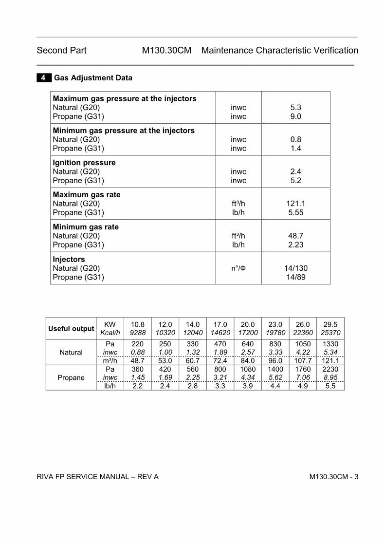
4 Gas Adjustment Data
Maximum gas pressure at the injectorsNatural (G20)Propane (G31)
inwcinwc
5.39.0
Minimum gas pressure at the injectorsNatural (G20)Propane (G31)
inwcinwc
0.81.4
Ignition pressureNatural (G20)Propane (G31)
inwcinwc
2.45.2
Maximum gas rateNatural (G20)Propane (G31)
ft³/hlb/h
121.15.55
Minimum gas rateNatural (G20)Propane (G31)
ft³/hlb/h
48.72.23
InjectorsNatural (G20)Propane (G31)
n°/Ф 14/13014/89
Useful output KWKcal/h
10.89288
12.010320
14.012040
17.014620
20.017200
23.019780
26.022360
29.525370
Painwc
2200.88
2501.00
3301.32
4701.89
6402.57
8303.33
10504.22
13305.34Natural
m³/h 48.7 53.0 60.7 72.4 84.0 96.0 107.7 121.1Pa
inwc3601.45
4201.69
5602.25
8003.21
10804.34
14005.62
17607.06
22308.95Propane
lb/h 2.2 2.4 2.8 3.3 3.9 4.4 4.9 5.5

___________________________________________________________________________________________________
Second Part M130.30CM Maintenance Characteristic Verification_______________________________________________________________
RIVA FP SERVICE MANUAL REV A M130.30CM - 4
5 Fault Finding
___________________________________________________________________________________________________
Second Part M130.30CM Maintenance Characteristic Verification_______________________________________________________________
RIVA FP SERVICE MANUAL REV A M130.30CM - 5
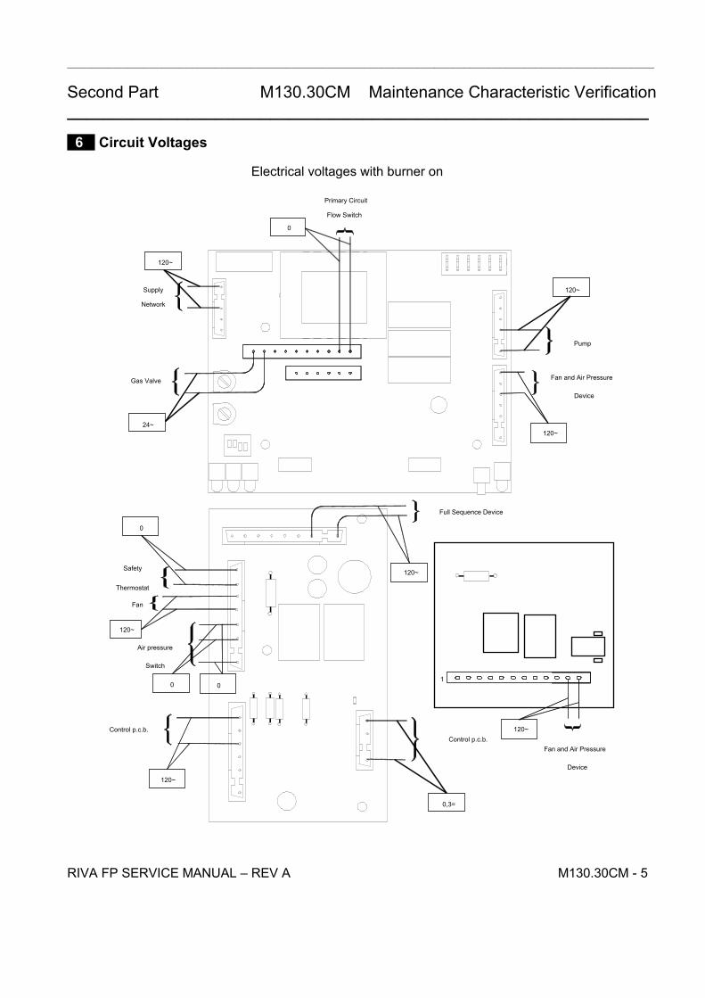
6 Circuit Voltages
Flow Switch
Primary Circuit
Pump
Supply
Network
Gas Valve
0
120~
120~
24~
Control p.c.b.
0,3=
Fan
Safety
Thermostat
0
120~
Air pressure
Switch
0 0
Control p.c.b.
120~
Fan and Air Pressure
Device
120~
Fan and Air Pressure
Device
Full Sequence Device
120~
120~
Electrical voltages with burner on
1
___________________________________________________________________________________________________
Second Part M130.30CM Maintenance Characteristic Verification_______________________________________________________________
RIVA FP SERVICE MANUAL REV A M130.30CM - 6
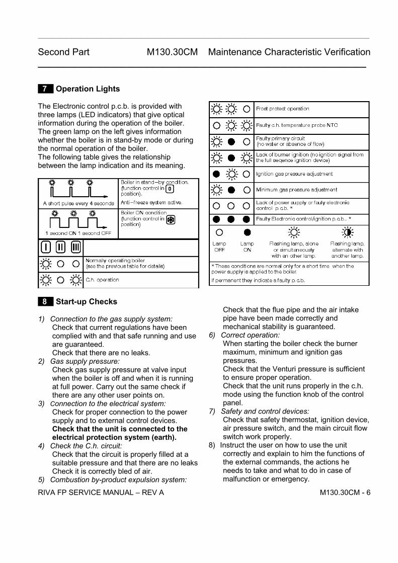
7 Operation Lights
The Electronic control p.c.b. is provided withthree lamps (LED indicators) that give opticalinformation during the operation of the boiler.The green lamp on the left gives informationwhether the boiler is in stand-by mode or duringthe normal operation of the boiler.The following table gives the relationshipbetween the lamp indication and its meaning.
8 Start-up Checks
1) Connection to the gas supply system:Check that current regulations have beencomplied with and that safe running and useare guaranteed.Check that there are no leaks.
2) Gas supply pressure:Check gas supply pressure at valve inputwhen the boiler is off and when it is runningat full power. Carry out the same check ifthere are any other user points on.
3) Connection to the electrical system:Check for proper connection to the powersupply and to external control devices.Check that the unit is connected to theelectrical protection system (earth).
4) Check the C.h. circuit:Check that the circuit is properly filled at asuitable pressure and that there are no leaksCheck it is correctly bled of air.
5) Combustion by-product expulsion system:
Check that the flue pipe and the air intakepipe have been made correctly andmechanical stability is guaranteed.
6) Correct operation:When starting the boiler check the burnermaximum, minimum and ignition gaspressures.Check that the Venturi pressure is sufficientto ensure proper operation.Check that the unit runs properly in the c.h.mode using the function knob of the controlpanel.
7) Safety and control devices:Check that safety thermostat, ignition device,air pressure switch, and the main circuit flowswitch work properly.
8) Instruct the user on how to use the unitcorrectly and explain to him the functions ofthe external commands, the actions heneeds to take and what to do in case ofmalfunction or emergency.

___________________________________________________________________________________________________
Second Part M130.30CM Maintenance Characteristic Verification_______________________________________________________________
RIVA FP SERVICE MANUAL REV A M130.30CM - 7
9 Gas Conversion
1) Check that the gas cock fitted on the gassupply pipe is turned off and the appliance isswitched off at the circuit breaker.
2) Remove the front and side panels of the case.3) Take off the lid of the sealed chamber.4) Remove the front panel of the combustion
chamber.
A
A
7
Figure 9.15) Loosen the screws A and remove the burner 7
(Figure 9.1).6) Carry out the conversion for the type of gas,
replacing the burner injectors correctly.7) Reassemble the burner, the front panel of the
combustion chamber and the lid of the sealedchamber.
8) Extract the control panel.9) Loosen the screws D and remove the service
panel (Figure 9.2).
D
D
D
Figure 9.210) Set correctly the dip-switch "2" to the correct
position (Figure 9.3) in accordance with thefollowing table.
Gas supply Position of the switch 2Natural gas On
L.P.G. Off
ON
OFF
1 2 3 4
ON
OFF
12
3 4
Natural gas L.P.G.
Figure 9.511) Close the service panel.12) Turn on the boiler.13) Calibrate the gas valve according to the
instructions given in the section 7 of the thirdpart of this manual.
14) Set the correct gas pressure for centralheating output required.
15) Stick on the inside of the left hand side paneladjacent to the data badge the self-adhesivelabel (included with the conversion kit)indicating the type of gas, and the gaspressures to which the appliance has beenset.
16) Reassemble the front and side panels of thecase.
___________________________________________________________________________________________________
Second Part M130.30CM Maintenance Characteristic Verification_______________________________________________________________
RIVA FP SERVICE MANUAL REV A M130.30CM - 8

Summary General Access and Emptying the Hydraulic Circuits
Nomenclature 1-1 Body Panels 1-1 Control Panel 1-2 Access to the Sealed Chamber 1-2 Emptying the Primary Circuit 1-2
Primary Heat Exchanger
Function 2-1 Removal 2-1 Cleaning 2-2
Pump
Function 3-1 Checks 3-1 Removal 3-1
Three Way Diverter Valve
Function 4-1 Checks 4-1 Removal of Electric Actuator 4-1 Removal of Diverter Group and Its Internal Parts 4-2
Control p.c.b. 11.62
Function 5-1 Selection and Adjustment Devices 5-1 Checking the Temperature 5-2 Operation Lights 5-2 Dip-switch Selectors 5-3 Ignition Gas Pressure Adjustment 5-4 Max C.h. Power Regulation 5-4 Anti-frost System 5-4 Uniform Temperature System 5-4 Hydraulic Parts Checking System 5-4 Advanced Probe Control System 5-4 Checks 6-5 Removal of the Control p.c.b. 5-5 Thermal Control in Winter Mode 5-6
Thermal Control in Summer Mode 5-6
RIVA FP SERVICE MANUAL - REV A
Fan and Air Pressure Device 11.61
Function 6-1 Checks 6-1 Removal 6-1
Full Sequence Ignition Device S4567A-1019
Function 7-1 Checks 7-1 Removal 7-1 Ignition and Control Sequence 7-2
Modulating Gas Valve
Function 8-1 Nomenclature 8-1 Adjustment 8-1 Checks 8-2 Removal of the Gas Valve 8-2
Primary Circuit Flow Switch
Function 9-1 Checks 9-1 Removal 9-1
DHW Flow Switch, Filter
Function 10-1 Nomenclature 10-1 Checks 10-1 Removal 10-1
Expansion Vessels and Temperature-Pressure Gauge
Function 11-1 Checks 11-1 Removal of the C.h. Expansion Vessel 11-1 Removal of the D.h.w. Expansion Vessel 11-2 Removal of the Temperature-Pressure Gauge 11-2
Temperature Probe NTC
Function 12-1 Checks 12-1 Removal 12-1
RIVA FP SERVICE MANUAL - REV A
Fan, Venturi Device and Air Pressure Switch
Function 13-1 Checks 13-1 Removal of the Fan 13-2 Inspection and Removal of the Venturi Device 13-2 Removal of the Air Pressure Switch 13-2
Ignition and Detection Electrodes, Burner and Injectors
Function 14-1 Checks 14-1 Removal 14-1
Safety Thermostat Function 15-1 Checks 15-1 Removal 15-1
Electric Resistances
Pump Resistance 16-1 Gas Valve Resistance 16-1 Temperature Probe NTC Resistance 16-1 Fan Resistance 16-1
Short Spare Parts List 17-1 RIVA FP SERVICE MANUAL - REV A

___________________________________________________________________________________________________
Third Part (edition-0106) General Access and Emptying Hydraulic Circuits_______________________________________________________________
RIVA FP SERVICE MANUAL REV A 1-1
1 Nomenclature
1
2
3
45
Figure 11) Right Side Panel2) Front Panel3) Control Panel Lid4) Control Panel Cover5) Left Side Panel
2 Body Panels
Warning: Isolate the boiler from the mainselectricity supply before removing anycovering or component.
For the most part of the check and maintenanceoperations it is necessary to remove one or morepanels of the case.
The side panels can be removed only after theremoval of the front panel.To remove the front panel remove screws A(Figure 2) , lift the panel and remove it.
A
A
Figure 2To remove the side panels, remove the screws B(Figure 3) and loosen the screws C (Figure 3),bring the base of the panels away from the boiler(Figure 4) and lift them, freeing them from the tophooks.
BB
CC
BB
Figure 3
Figure 4
General Access and EmptyingHydraulic Circuits
1) Nomenclature2) Body Panels3) Control Panel4) Access to the Sealed Chamber5) Emptying the Primary Circuit

___________________________________________________________________________________________________
Third Part (edition-0106) General Access and Emptying Hydraulic Circuits_______________________________________________________________
RIVA FP SERVICE MANUAL REV A 1-2
3 Control Panel
Warning: Isolate the boiler from the mainselectricity supply before removing anycovering or component.
To gain access to the parts located inside thecontrol panel proceed as follows:
1) Remove the front panel of the case.2) Loosen the screws and B and C (Figure 3).3) Move the lower part of the side panels as
indicated in Figure 4 and pull the controlpanel. When completely pulled out, the panelcan rotate 45° downwards to facilitate theservice operations on the internal parts.
D
D
DE
EE
E
E
Figure 54) Remove the screws D and remove the service
panel (Figure 5).5) To gain access to the electronic control p.c.b.
and the fan and air pressure device removethe screws E and remove the control panel lid(Figure 5).
4 Access to the Sealed Chamber
To gain access to the parts contained in thesealed chamber it is necessary to remove the lidof the sealed chamber.
For this purpose, remove the front and sidepanels of the case, remove the screws F asindicated in Figure 6 and remove the lid.
F
F
Figure 6
5 Emptying the Primary Circuit
1) Close the pressure reducing automatic fillvalve.
2) Open the c.h. drain cock G (Figure 7).3) Empty the C.h. System.4) Close the c.h. drain cock G.5) Open the pressure reducing automatic fill
valve.
G
Figure 7

___________________________________________________________________________________________________
Third Part (edition-0106) Primary Heat Exchanger_______________________________________________________________
RIVA FP SERVICE MANUAL REV A 2-1
1 Function
The primary heat exchanger A in Figure 1 hasthe function of transferring heat produced fromcombustion of the gas to the water circulating init.
A
Figure 1The hydraulic circuit is composed of 8 ellipticalpipes connected in parallel (Figure 2).
Figure 2
2 Removal
1) Remove the case panels.2) Empty the primary circuit.3) Remove the sealed chamber lid.4) Remove the front panel B of the combustion
chamber by unscrewing the screws C (Figure3).
5) Remove the screw D and the deflector E.6) Remove the clips F (Figure 3).
C
B
F
E
D
Figure 37) Loosen the connection G, rotate to the left and
then move downwards the pipe H freeing itfrom the connection of the primary heatexchanger (Figure 4).
G
HI
J
Figure 4
Primary Heat Excanger
1) Function2) Removal3) Cleaning

___________________________________________________________________________________________________
Third Part (edition-0106) Primary Heat Exchanger_______________________________________________________________
RIVA FP SERVICE MANUAL REV A 2-2
8) Completely unscrew the connection J androtate the pipe I downwards freeing it fromthe heat exchanger connection (Figure 4)
9) Remove the heat exchanger by sliding itforwards.
10) Reassemble the boiler carrying out theremoval operations in reverse order. Fit theclip F with the arrow pointing upwards asillustrated in Figure 3.
3 Cleaning
If there are deposits of soot or dirt between theblades of the heat exchanger, clean with a brushor non-metallic bristle brush.In any case, avoid any actions that can damagethe protective varnish with which the exchangerhas been covered.
___________________________________________________________________________________________________
Third Part (edition-0106) Pump_______________________________________________________________
RIVA FP SERVICE MANUAL REV A 3-1
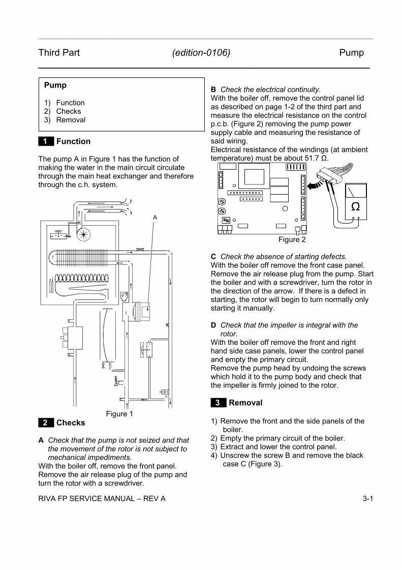
1 Function
The pump A in Figure 1 has the function ofmaking the water in the main circuit circulatethrough the main heat exchanger and thereforethrough the c.h. system.
A
Figure 1 2 Checks
A Check that the pump is not seized and thatthe movement of the rotor is not subject tomechanical impediments.
With the boiler off, remove the front panel.Remove the air release plug of the pump andturn the rotor with a screwdriver.
B Check the electrical continuity.With the boiler off, remove the control panel lidas described on page 1-2 of the third part andmeasure the electrical resistance on the controlp.c.b. (Figure 2) removing the pump powersupply cable and measuring the resistance ofsaid wiring.Electrical resistance of the windings (at ambienttemperature) must be about 51.7 Ω.
Figure 2
C Check the absence of starting defects.With the boiler off remove the front case panel.Remove the air release plug from the pump. Startthe boiler and with a screwdriver, turn the rotor inthe direction of the arrow. If there is a defect instarting, the rotor will begin to turn normally onlystarting it manually.
D Check that the impeller is integral with therotor.
With the boiler off remove the front and righthand side case panels, lower the control paneland empty the primary circuit.Remove the pump head by undoing the screwswhich hold it to the pump body and check thatthe impeller is firmly joined to the rotor.
3 Removal
1) Remove the front and the side panels of theboiler.
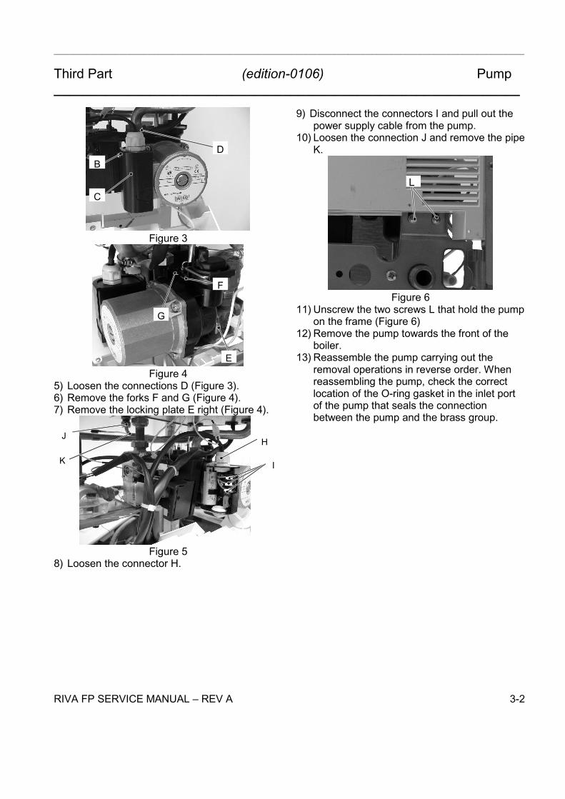
2) Empty the primary circuit of the boiler.3) Extract and lower the control panel.4) Unscrew the screw B and remove the black
case C (Figure 3).
Pump
1) Function2) Checks3) Removal
___________________________________________________________________________________________________
Third Part (edition-0106) Pump_______________________________________________________________
RIVA FP SERVICE MANUAL REV A 3-2
B
C
D
Figure 3
E
F
G
Figure 45) Loosen the connections D (Figure 3).6) Remove the forks F and G (Figure 4).7) Remove the locking plate E right (Figure 4).
H
I
J
K
Figure 58) Loosen the connector H.
9) Disconnect the connectors I and pull out thepower supply cable from the pump.
10) Loosen the connection J and remove the pipeK.
L
Figure 611) Unscrew the two screws L that hold the pump
on the frame (Figure 6)12) Remove the pump towards the front of the
boiler.13) Reassemble the pump carrying out the
removal operations in reverse order. Whenreassembling the pump, check the correctlocation of the O-ring gasket in the inlet portof the pump that seals the connectionbetween the pump and the brass group.

Three way diverter valve
1 Function
The diverter valve A (Fig. 1) has the function of modify- ing the hydraulic circuit of the boiler by means of an electriccommandgivenby the electroniccontrol p.c.b. in order to send the water that exitstheprimary heat ex- changer towards the c.h. system or towardsthe d.h.w. heat exchanger.
A
Fig. 1
2 Checks
n Check the electrical continuity
Fig. 2 indicates the relationship between the electric command coming from the electronic control p.c.b. and the position of the actuator B (brassspindle) when the boiler operates in d.h.w. mode.
Fig. 3 indicates the relationship between the electric command coming from the electronic control p.c.b. and the positionof the actuator B (brassspindle) when the boiler operates in c.h. mode.
the actuator and the resistance of the motor windings (the motor must be disconnected from the wiring) is also given.
B
wh rd bk
rd =red wh=white bk =black
0V 120V
Spindle B not visible
Open circuit
2.6 Kohm
3
1
2
Fig. 2 --- D.h.w. mode
B
rd =red wh=white bk =black
120
V 0V wh rd bk
Spindle B visible
Open circuit
2.6 Kohm
3
1
2
Fig. 3 --- C.h. mode
3 Removal of the electric actuator
Warning: isolate the boiler from the mains electricity supply before removing any covering or component.
1 Remove the front case panel. 2 Disconnect the connectors C (Fig. 4).
D and remove the actuator E . Reassemble the actuator carrying out the re- moval operations in the reverse order. When reassembling the actuator, refer to Fig. 2or to the wiring diagram in section 3.1 for the correct wiring connection.
RIVA FP SERVICE MANUAL - REV A 4-1
(edition-0106)Third Part

D
C E
Fig. 4
4 Removal of the diverter group and its internal parts
1 Remove the front and both side case panels.
2 Empty the primary circuit and the d.h.w circuit of the boiler.
3 Remove the electric actuator (see section 8.3).
4 Remove the ÿxing spring F (Fig. 5) and remove the primary circuit ° ow switch G .
5 Disconnect the c.h. temperature probe H. 6 Unscrew the connector I, the c.h. °o w connector
and the d.h.w. outlet connector.
F
G I H
Fig. 5
7 Remove the d.h.w. heat exchanger (see section 6.2).
8 Remove the fork J and move away the pipe K (Fig. 6).
9 Unscrew the screw L and remove the diverter group.
J
K
L
Fig. 6 Rear view of the boiler
10 Referto theexplodedview in Fig. 7 to remove the internal parts of the three way diverter valve.
Fig. 7
11 Reassemble the diverter group carrying out the removal operations in the reverse order.
Three way diverter valve(edition-0106)Third Part
RIVA FP SERVICE MANUAL - REV A 4-2

___________________________________________________________________________________________________
Third Part (edition-0106) Control p.c.b. 11.62_______________________________________________________________
RIVA HEAT ONLY SERVICE MANUAL REV A 5-1
1 Function
From other boiler devices....C.h. temperature probe NTCPrimary circuit flow switchRoom thermostat (if fitted)Flame presence signal**from the full sequence ignition device
On the Electronic control p.c.b.......Function control*C.h. temperature adjustment*Function dip-switchesMax c.h. power adjustmentIgnition gas pressure adjustmentBoiler reset button**control panel fascia
Inlet Information
PumpFull sequence ignition deviceModulation operatorAppliance operation lights*Lock-out signal lamp**control panel fascia
Outlet command
The fundamental function of the Control p.c.b. isthat of controlling the boiler in relation to theexternal needs (i.e. heating the dwelling) andoperating in order to keep the temperature of thehydraulic circuits constant.This is obviously possible within the useful powerand maximum working temperature limitsforeseen.Generally, the Control p.c.b. receives inletinformation coming from the boiler (the sensors)or from the outside (knob, room thermostat, etc.),processes it and consequently acts with outletcommands on other components of the boiler.
2 Selection and Adjustment Devices
On the Control p.c.b. several selection,adjustment and protection devices are located.(Figure 1).Some of these devices are directly accessible bythe user (function control, temperatureadjustment potentiometers etc.) others areaccessible by removing the service panel or thecontrol panel lid.
K
J
I
H
G
F ED
C
B
A
Figure 1A) J3 connectorB) J2 connectorC) Lock-out signal lamp
Control p.c.b. 11.62
1) Function2) Selection and Adjustment Devices3) Checking the Temperature4) Operation Lights5) Dip-switch Selector
6) Ignition Gas Pressure Adjustment7) Max C.h. Power Regulation8) Anti-frost System9) Hydraulic Parts Checking System10) Checks11) Removal of the Control p.c.b.12) Thermal Control

___________________________________________________________________________________________________
Third Part (edition-0106) Control p.c.b. 11.62_______________________________________________________________
RIVA FP SERVICE MANUAL REV A 5-2
D) Boiler reset buttonE) Function control / C.h. temp. adjustmentF) Appliance operation lightsG) Dip-switch selectorsH) Setting jumpersI) Ignition gas pressure adjustment (ACC.)J) J1 connectorK) Fuse 4.0 A
3 Checking the Temperature
The control p.c.b. makes it possible to adjust thec.h. water flow temperature.The temperature of the water is converted into anelectric signal by means of temperature probes.The user, setting the desired temperature withthe control panel knob operates the variableelement (E in Figure 1) of the control p.c.b.If the power requested is lower than 40% of themaximum power output then control is achievedby switching ON the burner at minimum power,then switching OFF (ON/OFF function). If thepower requested is higher, then the burner isswitched ON at maximum power and will controlby modulating to 40% of the max power output.
Figure 2
During the c.h. operation (Figure 2), the signalcoming from the c.h. temperature probe iscompared to the signal given by the control panelthrough the adjustment made by the user (knobin Figure 2). The result of such a comparisonoperates the modulation of the gas valve,consequently changing the useful output of theboiler.The control sequence is illustrated in detail insections 12.
4 Operation Lights
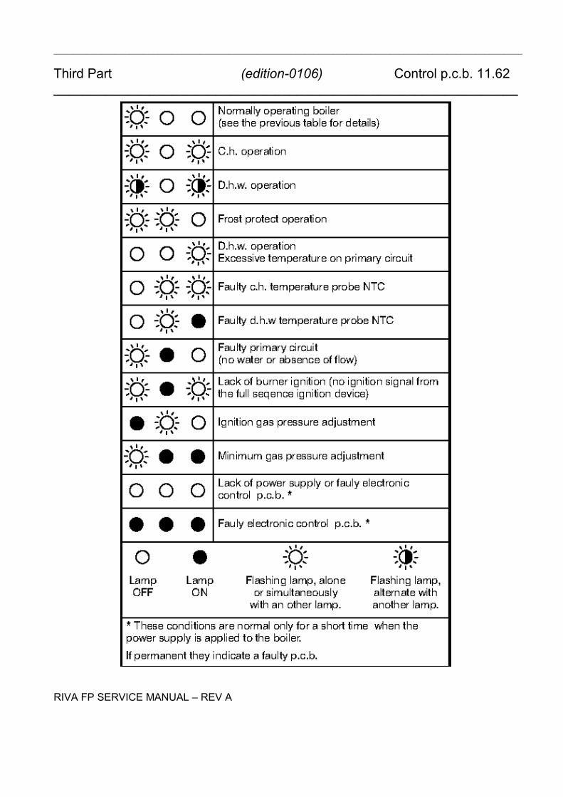
The Control p.c.b. is provided with three lamps(L.E.D. indicators) F in Figure 1 that give opticalinformation during the operation of the boiler.The green lamp on the left gives informationwhether the boiler is in stand-by mode or duringthe normal operation of the boiler.The following table gives the relationshipbetween the lamp indication and its meaning.
Figure 3With the boiler switched ON all the lamps (F inFigure 1) are activated.The following table gives the relationshipbetween each of the possible lamp combinationsand their meaning.
___________________________________________________________________________________________________
Third Part (edition-0106) Control p.c.b. 11.62_______________________________________________________________
RIVA FP SERVICE MANUAL REV A
___________________________________________________________________________________________________
Third Part (edition-0106) Control p.c.b. 11.62_______________________________________________________________
RIVA FP SERVICE MANUAL REV A 5-3
Figure 4 5 Dip-switch Selectors
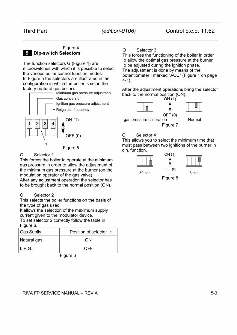
The function selectors G (Figure 1) aremicroswitches with which it is possible to selectthe various boiler control function modes.In Figure 5 the selectors are illustrated in theconfiguration in which the boiler is set in thefactory (natural gas boiler).
1 2 3 4ON (1)
OFF (0)
H
Gas conversionIgnition gas pressure adjustmentReignition frequency
Minimum gas pressure adjustmen
t
Figure 5O Selector 1This forces the boiler to operate at the minimumgas pressure in order to allow the adjustment ofthe minimum gas pressure at the burner (on themodulation operator of the gas valve).After any adjustment operation the selector hasto be brought back to the normal position (ON).
O Selector 2This selects the boiler functions on the basis ofthe type of gas used.It allows the selection of the maximum supplycurrent given to the modulator device.To set selector 2 correctly follow the table inFigure 6.Gas Suplly Position of selector
Natural gas ON
L.P.G. OFFFigure 6
O Selector 3This forces the functioning of the boiler in order
t
o allow the optimal gas pressure at the burner
t
o be adjusted during the ignition phase.The adjustment is done by means of thepotentiometer I marked ACC" (Figure 1 on page4-1).
After the adjustment operations bring the selectorback to the normal position (ON).
gas pressure calibration Normal
ON (1)
OFF (0)
Figure 7
O Selector 4This allows you to select the minimum time thatmust pass between two ignitions of the burner inc.h. function.
30 sec. 3 min.
ON (1)
OFF (0)
Figure 8

___________________________________________________________________________________________________
Third Part (edition-0106) Control p.c.b. 11.62_______________________________________________________________
RIVA FP SERVICE MANUAL REV A 5-4
6 Ignition Gas Pressure Adjustment
By using the device "I" (Figure 1) marked ACC.",it is possible to adjust the gas pressure at theinjectors in the ignition phase.This pressure is maintained at the injectors untilignition occurs (ionization signal).To carry out the adjustment move the functionselector 3 to the OFF position (Figure 7) and usethe adjustment device "I" (ACC).Adjust the gas pressure at the injectors to thevalue indicated in the tables of theUser/Installation manual (Technical informationsection, Gas pressures at the burner table).By rotating the device clockwise the pressureincreases.Check the regular ignition of the burner byturning the boiler on and off repeatedly.After the adjustment operations bring the selector3 back to the normal position ON in Figure 7.
7 Max C.h. Power Regulation
By using the device I (Figure 1) marked RISC.,it is possible to limit the maximum useful outputdelivered in c.h. function. By rotating the deviceclockwise the pressure increases.
8 Anti-frost System
With the boiler turned on, the anti-frost control isalways active, which briefly starts the boiler untilshutdown at 35°C (primary circuit), so that thetemperature of the c.h. circuit does not dropbelow 5°C.The request is signalled by the LED Fin Figure 1.If there is no gas, the pump runs continuously tokeep the water from freezing.This function is also active in standby mode.
9 Hydraulic Parts Checking System
With the boiler operating (both in winter functionand in summer function) the hydraulic partschecking system is always active.
This system makes it possible to maintain theefficiency of the hydraulic parts (i.e. pump) byactivating them in case of long periods ofunusing.It is activated when the boiler is inactive for morethan 24 hours.A) It turns on the pump for 1 minute
10 Checks
A Check that the fuse is completeIf the control p.c.b. does not supply any device(pump, etc.) check that the fuse K (Figure 1) iscomplete.If the fuse has blown replace it with one that hasthe same characteristics after having identifiedthe reason for failure.
B Check the setting jumpers positionTwo setting jumpers must be fitted on the Controlp.c.b. as shown in Figure 9.
1 2 3 4 5 6 7 8 9Figure 9
The numbers refer to the marking printed on thecircuit board.
11 Removal of the Control p.c.b.
Warning: Isolate the boiler from the mainselectricity supply before removingany covering or component.
1) Gain access to the parts located inside thecontrol panel as explained on page 1-2 of thethird part of this manual.
2) Remove all the wiring connected to theControl p.c.b.. To disconnect the connectorsJ1, J2 and J3 (A,B and J in Figure 1)delicately flex the hook present on one side ofeach socket.
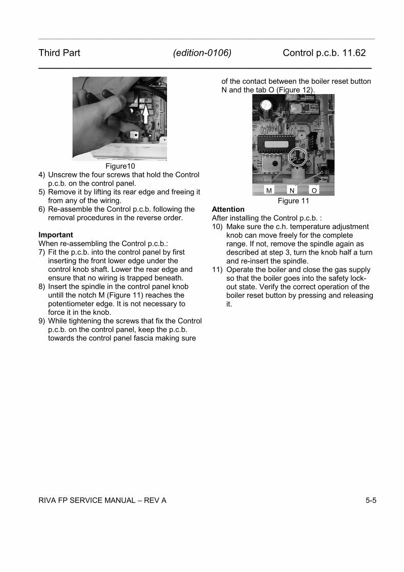
3) Remove the spindles of the c.h. temperatureadjustment knob by delicately pulling it withpliers in the direction shown by the arrow inFigure 10.
___________________________________________________________________________________________________
Third Part (edition-0106) Control p.c.b. 11.62_______________________________________________________________
RIVA FP SERVICE MANUAL REV A 5-5
Figure104) Unscrew the four screws that hold the Control
p.c.b. on the control panel.5) Remove it by lifting its rear edge and freeing it
from any of the wiring.6) Re-assemble the Control p.c.b. following the
removal procedures in the reverse order.
ImportantWhen re-assembling the Control p.c.b.:7) Fit the p.c.b. into the control panel by first
inserting the front lower edge under thecontrol knob shaft. Lower the rear edge andensure that no wiring is trapped beneath.
8) Insert the spindle in the control panel knobuntill the notch M (Figure 11) reaches thepotentiometer edge. It is not necessary toforce it in the knob.
9) While tightening the screws that fix the Controlp.c.b. on the control panel, keep the p.c.b.towards the control panel fascia making sure
of the contact between the boiler reset buttonN and the tab O (Figure 12).
M N OFigure 11
AttentionAfter installing the Control p.c.b. :10) Make sure the c.h. temperature adjustment
knob can move freely for the completerange. If not, remove the spindle again asdescribed at step 3, turn the knob half a turnand re-insert the spindle.
11) Operate the boiler and close the gas supplyso that the boiler goes into the safety lock-out state. Verify the correct operation of theboiler reset button by pressing and releasingit.

___________________________________________________________________________________________________
Third Part (edition-0106) Control p.c.b. 11.62_______________________________________________________________
RIVA FP SERVICE MANUAL REV A 5-6
12 Thermal Control
After 25 second circulator off and faulty primary cir
cuit (see LED table)
Switch in the function mode
Request for heat from room thermostat?
Circulator offOperates motorised valve
Ignition device not fed
YES
Primary circuit flow switch OK?
YES
NO
Is primary circuit temperature higher than that
selected?
NO
YES
NO
Operates motorised valveSupplies the ignition device
Starts the circulator
___________________________________________________________________________________________________
Third Part (edition-0106) Fan and Air Pressure Device 11.61_______________________________________________________________
RIVA FP SERVICE MANUAL REV A 6-1
1 Function
The Fan and air pressure device A (Figure 1)used on the boiler carries out the followingfundamental functions:O supplies the fan and checks its functioning by
means of the signal coming from the airpressure switch.
O supplies the air pressure switch and makes itcommutate.
O supplies the safety thermostat.The Fan and air pressure device is supplied bythe electronic control p.c.b. see Second part ofthis manual chapter 6 (Circuit Voltages).The Fan and air pressure device also has asafety function and any wrong interventions ortamperings could cause the boiler to functionunder hazardous operating conditions.The Fan and air pressure device can lock thefunctioning of the boiler (lock state) and stop itsfunctioning up to the resetting intervention. Thelock is signalled by the lighting of the lock-outsignal lamp and the device can be reset only byusing the boiler reset button and the functionknob placed on the control panel.Some components which are connected to thedevice can activate the lock state. The causes ofa lock state could be:O The intervention of the safety thermostat(overheat of the primary circuit).O The air pressure switch can temporarily stopthe ignition of the burner but allow its ignitionwhen the cause of the intervention has stopped.
2 Checks
A Fan and Air Press. Switch functioning deviceWith the boiler operating and the burner on, openthe negative pressure test point of the Venturidevice.
At the moment of opening the burner must turnoff.
B Checking VoltagesRefer to Second part of manual chapter 6 todetermine the connector pins where to check thesupply voltages.
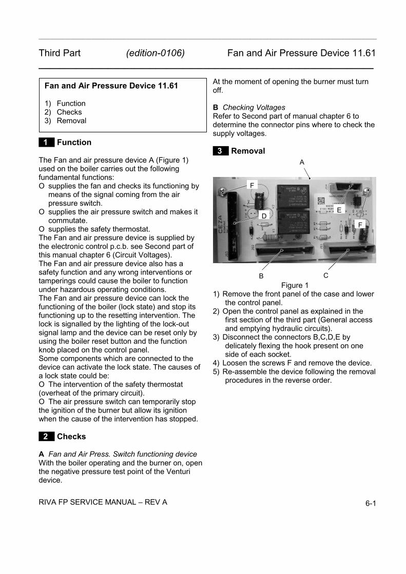
3 RemovalA
B C
DE
F
F
Figure 11) Remove the front panel of the case and lower
the control panel.2) Open the control panel as explained in the
first section of the third part (General accessand emptying hydraulic circuits).
3) Disconnect the connectors B,C,D,E bydelicately flexing the hook present on oneside of each socket.
4) Loosen the screws F and remove the device.5) Re-assemble the device following the removal
procedures in the reverse order.
Fan and Air Pressure Device 11.61
1) Function2) Checks3) Removal

___________________________________________________________________________________________________
Third Part (edition-0106) Full Sequence Ignition Device S4567A-1019_______________________________________________________________
RIVA FP SERVICE MANUAL REV A 7-1
1 Function
The Full sequence ignition device A (Figure1)used on the boiler carries out the followingfundamental functions:
A
B
Figure 1O does a sequence of operations (ignition cycle)which lead to the ignition of the gas at the burner.O checks the presence of the flame during theentire period in which it is activated.The Full sequence ignition device is supplied bythe fan and air pressure device when the ignitionof the burner is requested (see Second part ofthis manual chapter 6, Circuit Voltages).The Full sequence ignition device has a safetyfunction and any incorrect interventions ortampering can result in conditions of dangerousfunctioning of the boiler.The Full sequence ignition device can lock thefunctioning of the boiler (lock state) and stop itsfunctioning up to the resetting intervention. Thelock is signalled by the lighting of the lock-outsignal lamp and the device can be reset only byusing the boiler reset button and the functionknob placed on the control panel.The ignition device has some componentsconnected to it which can cause triggering of theshutdown condition; these components are:
- the modulating gas valve;- the flame detection electrode.
The causes of a lock state could be:
O A fault on gas supply.O Faulty ignition (faulty ignition electrodes, theirwiring or connection).O Faulty flame detection (faulty detectionelectrode, its wiring or connection).O Gas injectors blocked.O Faulty modulation gas valve (faulty on-offoperators or not electrically supplied).O Faulty Full sequence ignition device.Section 4 shows the sequence of the operationsthat are carried out at the start of every ignitioncycle and during normal functioning.
2 Checks
A Lock sequence1) Start the boiler until the burner is ignited.2) With the burner firing, interrupt the gas supply.
The Full sequence ignition device must carryout a complete ignition cycle and then stop.
3) By turning the boiler on and off by means ofthe function switch the device must notunlock and the burner must not turn on.
3 Removal
1) Remove the front body panel and tilt the cardholder panel.
C
D
E
F
Figure 22) Unscrew the screw C and remove protection
cover D of the connection; disconnect flamedetection cable E and ignition cable F (Figure2).
Full Sequence Ignition Device S4567A-1019
1) Function2) Checks3) Removal4) Ignition and Control Sequence
___________________________________________________________________________________________________
Third Part (edition-0106) Full Sequence Ignition Device S4567A-1019_______________________________________________________________
RIVA FP SERVICE MANUAL REV A 7-2
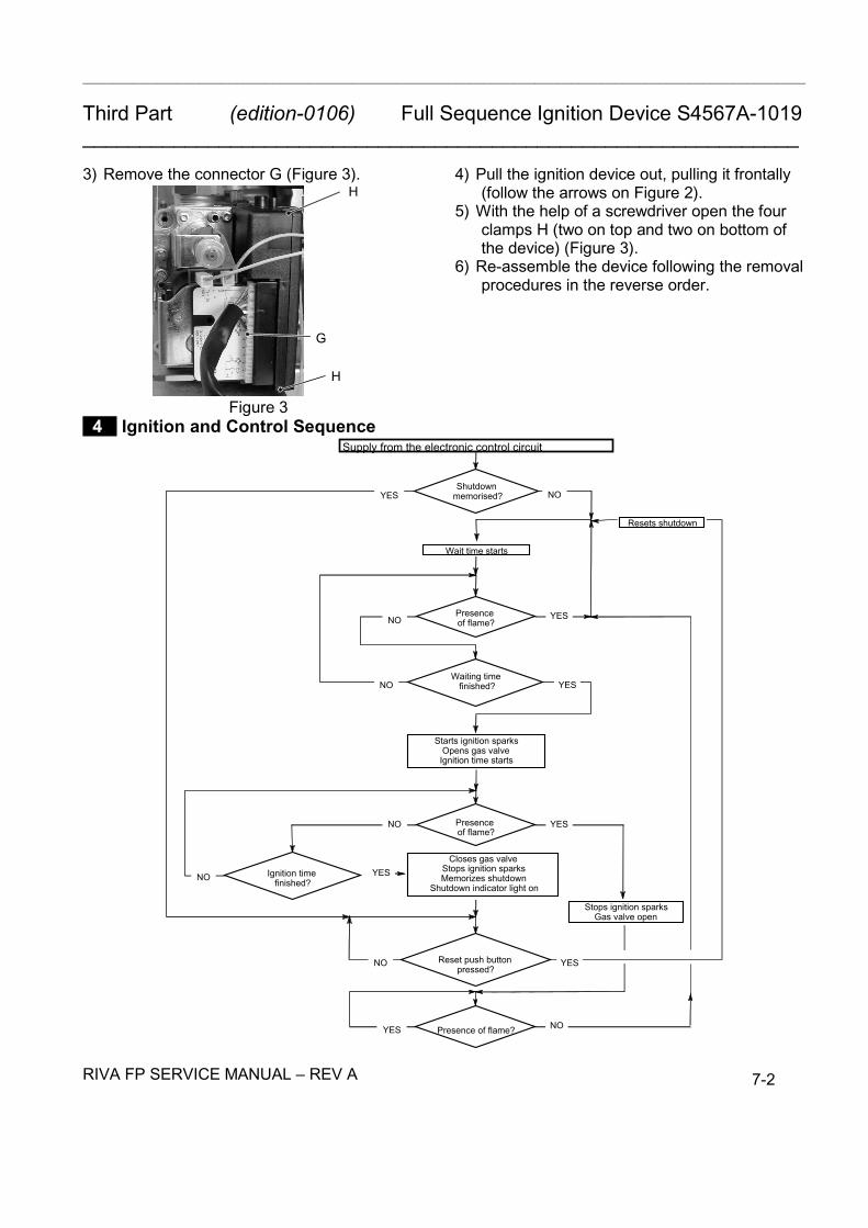
3) Remove the connector G (Figure 3).
G
H
H
Figure 3
4) Pull the ignition device out, pulling it frontally(follow the arrows on Figure 2).
5) With the help of a screwdriver open the fourclamps H (two on top and two on bottom ofthe device) (Figure 3).
6) Re-assemble the device following the removalprocedures in the reverse order.
4 Ignition and Control Sequence
Shutdown memorised?
Supply from the electronic control circuit
NO
Wait time starts
Presence of flame?NO
Resets shutdown
YES
Waiting time finished?NO
YES
Starts ignition sparksOpens gas valveIgnition time starts
Presence of flame?
Ignition time finished?NO
NO YES
Closes gas valveStops ignition sparksMemorizes shutdown
Shutdown indicator light on
YES
Reset push button pressed?
NO YES
Stops ignition sparksGas valve open
Presence of flame?YES
YES
NO

___________________________________________________________________________________________________
Third Part (edition-0106) Modulating Gas Valve_______________________________________________________________
RIVA FP SERVICE MANUAL REV A 8-1
1 Function
The Modulating gas valve A in Figure 1 controlsthe gas inflow to the boiler burner.
A
Figure 1By means of an electric command given to theon-off operators the passage of the gas throughthe Modulating gas valve can be opened orclosed.By means of an electric command given to themodulation operator the pressure can be variedand therefore the gas flow rate to the burner(modulation). The modulation operator hasmechanical components which allow theadjustment of the minimum and maximumpressure exiting the valve.
2 Nomenclature
B Minimum gas pressure adjustment.C Maximum gas pressure adjustment.D Modulation operator's electric connectors.E On-off operators electric connector.F On-off operators.G Gas valve inlet pressure test point.H Gas valve outlet pressure test point.I Modulation operator.
3 Adjustment
Warning: isolate the boiler from the mainselectricity supply before removing anycovering or component.
1) Remove the front panel of the case.2) Open the gas valve inlet pressure test point
(G in Figure 2) at the valve input, connect asuitable pressure gauge and check the gaspressure of the supply network.
3) Remove the gauge and close the pressuretest point G.
4) Open the gas valve outlet pressure test point(H in Figure 2) and connect the gauge.
G
H
F
D
E
C B
Q
I ML
Figure 2 Figure 35) Remove the protection cap L (Figure 3) from
the mechanical pressure adjustmentcomponents levering with a flat screwdriver inthe slots M.
6) Start the boiler at its maximum power. Ensurethat the boiler is not range rated.
7) Rotate the maximum gas pressure adjustment(C in Figure 2) until you obtain the requiredpressure (by rotating clockwise the pressureincreases).
8) Turn the boiler off and disconnect one of thetwo connectors (D in Figure 2).
Modulating Gas Valve
1) Function2) Nomenclature3) Adjustment4) Checks5) Removal of the Gas Valve
___________________________________________________________________________________________________
Third Part (edition-0106) Modulating Gas Valve_______________________________________________________________
RIVA FP SERVICE MANUAL REV A 8-2
9) Start the boiler and rotate the minimum gaspressure adjustment (B in Figure 2) until youobtain the required pressure (by rotatingclockwise the pressure increases).
10) Turn the boiler off and re-connect the wire tothe modulating operator.
11) Start the boiler and check again themaximum gas pressure setting.
12) Turn the boiler off and disconnect the gauge.
Important: after the gas pressure checks andany adjustment operations, all of the testpoints must be sealed.
4 Checks
A Check the modulation operator coil1) Remove the front panel of the case.2) Disconnect the connectors D (Figure 2) from
the modulating operator and measure theelectrical resistance of the coil. Its electricalresistance value must be approx. 114 Ω*.
B Check the on-off operators coils1) Remove the front panel of the case.2) Disconnect the Ignition device N (Figure 4).3) Measure the electrical resistance between the
connector pins of the on-off operators asillustrated in Figure 5.
N
Figure 4
On-off operatorapprox. 1 122 Ω*
* at ambient temperatureFigure 5
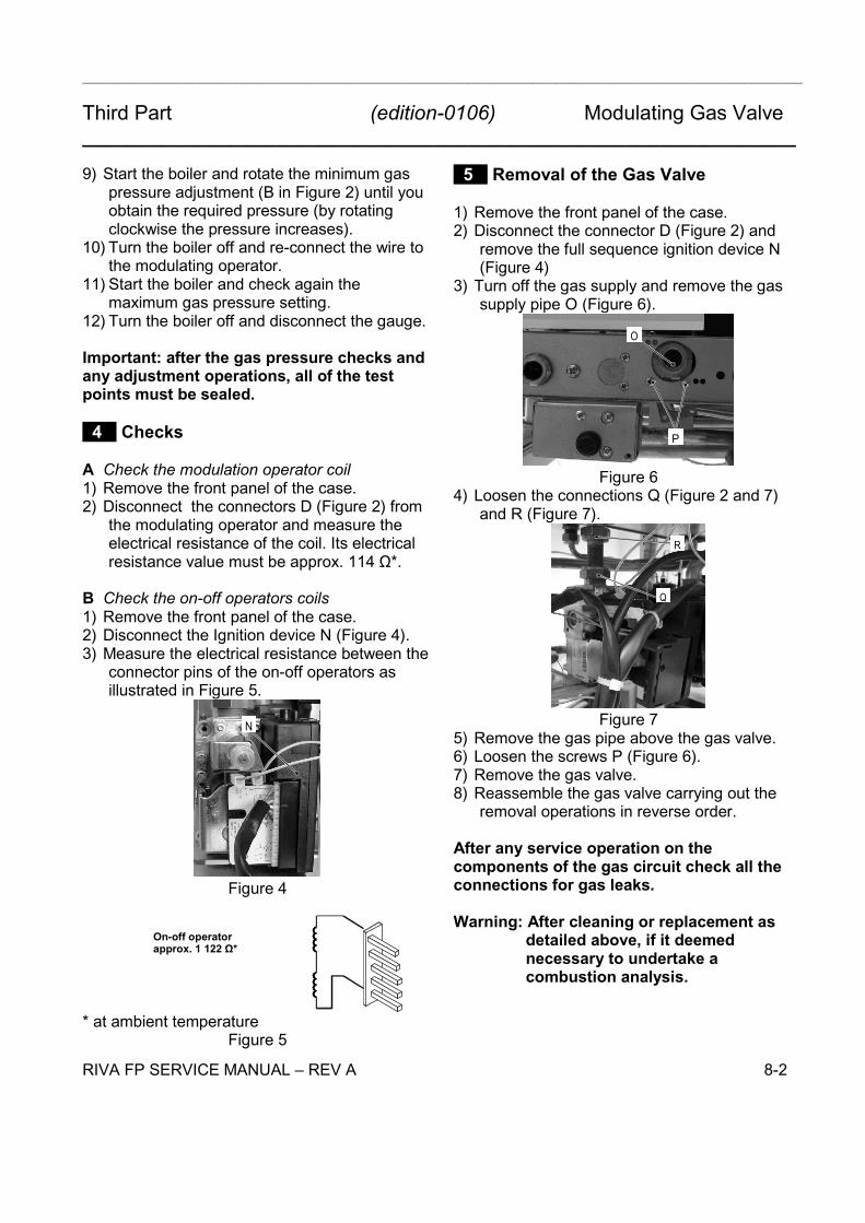
5 Removal of the Gas Valve
1) Remove the front panel of the case.2) Disconnect the connector D (Figure 2) and
remove the full sequence ignition device N(Figure 4)
3) Turn off the gas supply and remove the gassupply pipe O (Figure 6).
O
P
Figure 64) Loosen the connections Q (Figure 2 and 7)
and R (Figure 7).
R
Q
Figure 75) Remove the gas pipe above the gas valve.6) Loosen the screws P (Figure 6).7) Remove the gas valve.8) Reassemble the gas valve carrying out the
removal operations in reverse order.
After any service operation on thecomponents of the gas circuit check all theconnections for gas leaks.
Warning: After cleaning or replacement asdetailed above, if it deemednecessary to undertake acombustion analysis.

___________________________________________________________________________________________________
Third Part (edition-0106) Primary Circuit Flow Switch_______________________________________________________________
RIVA FP SERVICE MANUAL REV A 9-1
1 Function
The Primary circuit flow switch (A in Figure 1)function is to detect water flow rate through theprimary hydraulic circuit of the boiler.
A
Figure 1This hydraulic/membrane operated electricalmicro-switch device will control the functioning ofthe ignition control circuit, providing there is anadequate quantity and flow of water in theprimary circuit. Any failure of the pump orobstructions in the primary circuit will not allowthe device to operate.This device is connected to the electronic controlp.c.b. and if, after the pump operates, it does notactivate within 30 seconds the control board willindicate that a fault condition has occurred.
2 Checks
Warning: Isolate the boiler from the mainselectricity supply before removing anycovering or component.
A Mechanical function1) Remove the front panel of the case.2) Start and stop the boiler.3) Looking through the switch box verify the
position of the shaft B referring to Figure 2.
BBoiler OFF Boiler ONFigure 2
B Electrical checkIt is possible to verify the general operation of theswitch by measuring the electric resistancebetween the contacts C. and N.O. of the switch.1) Remove the switch as explained in next
section.2) Measure the electrical resistance between the
tabs marked C. and N.O. (Figure 3). Thecontact must be normally open.
3) Operate the switch by hand and verify that thecontact is now closed.
N.O.
do not use
C
Figure 3 3 Removal
Warning: Isolate the boiler from the mainselectricity supply before removingany covering or component.
A Removal of the switch1) Remove the front panel of the case.2) Remove the fork C (Figure 4).3) Open the box D (Figure 4) and disconnect the
switch.
Primary Circuit Flow Switch
1) Function2) Checks3) Removal
___________________________________________________________________________________________________
Third Part (edition-0106) Primary Circuit Flow Switch_______________________________________________________________
RIVA FP SERVICE MANUAL REV A 9-2
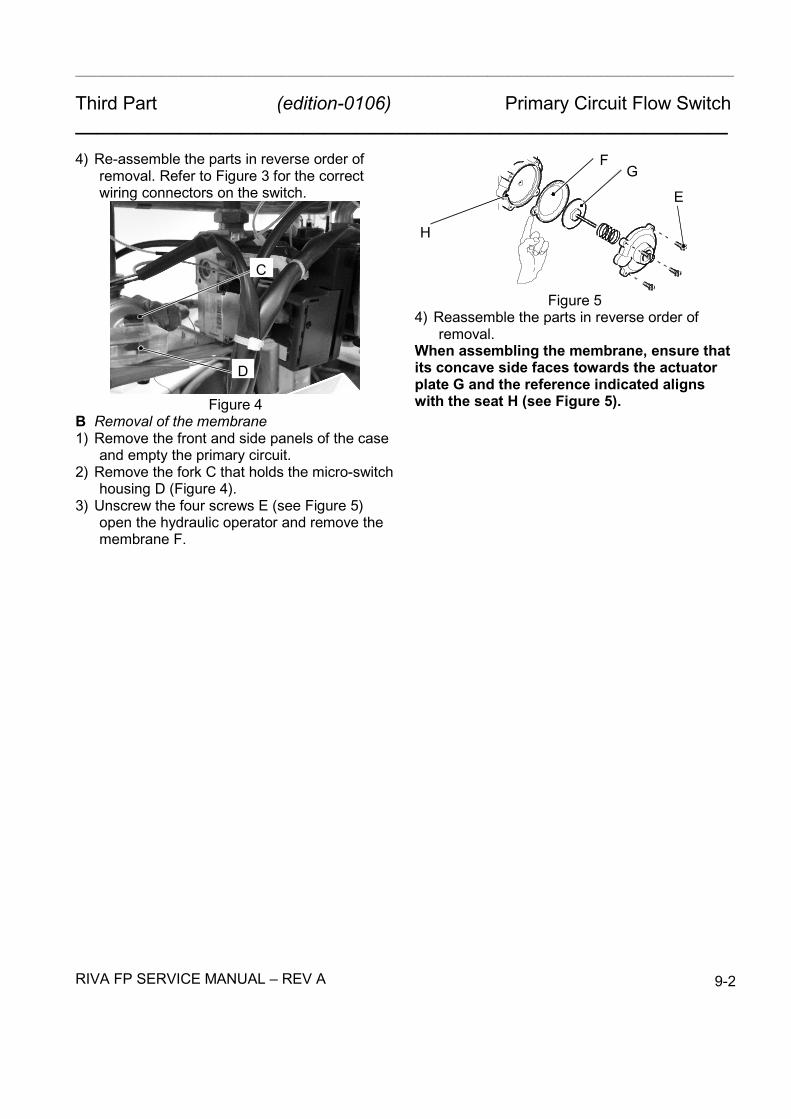
4) Re-assemble the parts in reverse order ofremoval. Refer to Figure 3 for the correctwiring connectors on the switch.
C
D
Figure 4B Removal of the membrane1) Remove the front and side panels of the case
and empty the primary circuit.2) Remove the fork C that holds the micro-switch
housing D (Figure 4).3) Unscrew the four screws E (see Figure 5)
open the hydraulic operator and remove themembrane F.
FG
H
E
Figure 54) Reassemble the parts in reverse order of
removal.When assembling the membrane, ensure thatits concave side faces towards the actuatorplate G and the reference indicated alignswith the seat H (see Figure 5).

13 D.h.w. ˜ow switch, ÿlter and ˜owlimiter
1 Function
The d.h.w. ˜ow switch A in Fig. 1 isa devicethat gener-ates an electrical signal when hot water is drawn.
A
Fig. 1
When the ˜ow rate through the d.h.w. circuit reachesabout .6 gal/min’, thefloat 6 (Fig. 3) is drawn to-wards the right.The resulting magnetic ÿeld of ring 5 increases and re-aches the ˜ow switch sensor 1.The sensor generatesan electrical signal that switchesthe boiler d.h.w operation ON.
Thestateof thesensor isalso indicatedbymeansof thelamp B placed on the sensor body.
B
C
Fig. 2
2 Nomenclature and location of parts(Fig. 3)
1 Flow switch sensor2 Body3 O---ring4 Spring5 Magnetic ring6 Float7 Threaded ring8 Flow limiter (optional accessory)9 Filter10 Spring seat
5
6
4
9
2
8
7
3
1
Fig. 3
3 Checks
Warning: isolate the boiler from the mainselectricity supply before removing anycovering or component.
n Flow switch sensor operation1 Remove the front panel of the case.2 Switch on the boiler and open a d.h.w. tap. The
lamp B (Fig. 2) placed on the sensor body isswitched on when the ˜ow rate reachesabout .6
gal /min’.
4 Removal of the f low switch sensor
Warning: isolate the boiler from the mainselectricity supply before removing anycovering or component.
1 Remove the front panel of the case.2 Disconnect the connector C (Fig. 2) and remove
the sensor by delicately lifting up.
DHW Flow Switch and Filter(edition-0106)Third Part
RIVA FP SERVICE MANUAL - REV A 10-1
___________________________________________________________________________________________________
Third Part (edition-0106) Expansion Vessel and Temperature-Pressure Gauge_______________________________________________________________
RIVA FP SERVICE MANUAL REV A 11-1
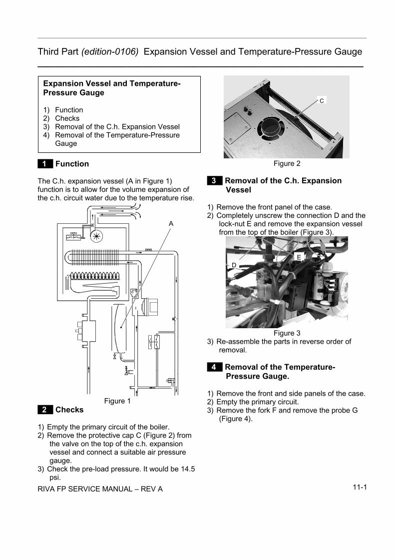
1 Function
The C.h. expansion vessel (A in Figure 1)function is to allow for the volume expansion ofthe c.h. circuit water due to the temperature rise.
A
Figure 1 2 Checks
1) Empty the primary circuit of the boiler.2) Remove the protective cap C (Figure 2) from
the valve on the top of the c.h. expansionvessel and connect a suitable air pressuregauge.
3) Check the pre-load pressure. It would be 14.5psi.
C
Figure 2
3 Removal of the C.h. ExpansionVessel
1) Remove the front panel of the case.2) Completely unscrew the connection D and the
lock-nut E and remove the expansion vesselfrom the top of the boiler (Figure 3).
DE
Figure 33) Re-assemble the parts in reverse order of
removal.
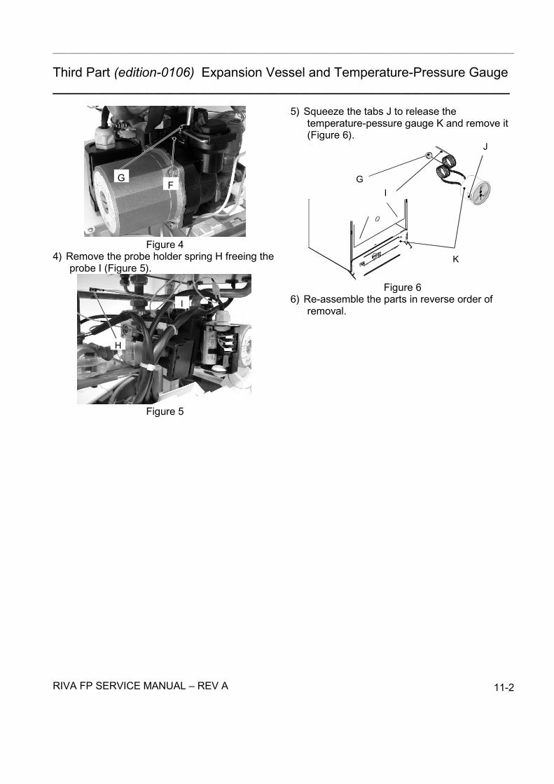
4 Removal of the Temperature-Pressure Gauge.
1) Remove the front and side panels of the case.2) Empty the primary circuit.3) Remove the fork F and remove the probe G
(Figure 4).
Expansion Vessel and Temperature-Pressure Gauge
1) Function2) Checks3) Removal of the C.h. Expansion Vessel4) Removal of the Temperature-Pressure
Gauge
___________________________________________________________________________________________________
Third Part (edition-0106) Expansion Vessel and Temperature-Pressure Gauge_______________________________________________________________
RIVA FP SERVICE MANUAL REV A 11-2
GF
Figure 44) Remove the probe holder spring H freeing the
probe I (Figure 5).
H
I
Figure 5
5) Squeeze the tabs J to release thetemperature-pessure gauge K and remove it(Figure 6).
K
J
GI
Figure 66) Re-assemble the parts in reverse order of
removal.

By---pass valve
1 Function
The By---pass valve A in Fig. 1 is located between the
changer if thecirculation acrossthec.h.system iscom-pletely closed.
erter group.
A
Fig. 1
2 Removal
Warning: isolate the boiler from the mainselectricity supply before removing anycovering or component.
1 Remove all the case panels.
2 Empty the primary circuit of the boiler.
3 Remove the diverter group as described in thesection 8.4 of this manual.
4 Unscrew the connector B and remove the by---pass valve C (Fig. 2).
C
B
Fig. 2
5 Reassemble the by---pass valve as illustrated inFig. 2 reversing the order of removal.
(edition-0106)Third Part
RIVA FP SERVICE MANUAL - REV A 12-1

___________________________________________________________________________________________________
Third Part (edition-0106) Fan, Venturi Device and Air Pressure Switch_______________________________________________________________
1 Function
The function of the Fan A (Figure 1) is to forcethe products of combustion to the outside air viathe flue system.The Fan is supplied by the Fan and air pressuredevice at the beginning of the ignition cycle.Its correct functioning is controlled by means of asystem incorporating a built in venturi device Band an Air pressure switch C (Figure 1).
A
CB
Figure 1
2 Checks
A Check of the fanWarning: Isolate the boiler from the mains
electricity supply before removingany covering or component.
1) Remove all the case panels and the sealedchamber lid.
2) Disconnect the connectors D (Figure 2) andmeasure the electrical resistance of the motorthat has to be about: 7.2 Ω.
D
E
F
Figure 2B Check of the Air pressure switch operationWarning: Isolate the boiler from the mains
electricity supply before removingany covering or component.
1) Remove all the case panels and the sealedchamber lid.
2) Disconnect the wires and check the electricalresistance between the connections of the Airpressure switch.
Refer to the Figure 3 in accordance with the typeof air pressure switch used.
N.O.
N.C.
"-" connection
COM
"+" connectionb l a c k
b ro w n
b luFigure 3
Between COM and N.O. the contact must beopen.Between COM and N.C.the contact must beclosed (electrical resistance zero).3) Connect the black (COM) and the brown wire
(N.C.).4) Run the boiler (the Fan must run) and check
the electric resistance between COM andN.O.. Between COM and N.O. the contactmust be closed (electrical resistance zero).
Fan, Venturi Device and Air PressureSwitch
1) Function2) Checks3) Removal of the Fan4) Inspection and Removal of the Venturi
Device5) Removal of the Air Pressure Switch
RIVA FP SERVICE MANUAL - REV A 13-1

___________________________________________________________________________________________________
Third Part (edition-0106) Fan, Venturi Device and Air Pressure Switch_______________________________________________________________C Check of the venturi deviceThis test must be carried out with the sealedchamber closed.1) Remove the caps of the pressure test points
located on the top of the boiler and connect adifferential pressure gauge (Figure 4).
2) Switch on the boiler.
Figure 43) Compare the value on the gauge with the
following minimum value: 0,64 inwc.
3 Removal of the Fan
1) Remove all the case panels and the sealedchamber lid.
2) Disconnect the connectors D and E (Figure 2).3) Disconnect the pipe F which connect the
venturi device to the pressure test point(Figure 2).
G G
Figure 54) Unscrew the screws G (Figure 5).5) Remove the fan by sliding it to the right.6) Re-assemble the fan carrying out the removal
operations in reverse sequence.Warning: Re-assembling the fan ensure that
the hooks around the inlet port ofthe fan hung correctly on the fluehood.
Warning: To correctly connect the venturidevice to the Air pressure switch,refer to Figure 6.
- +
Figure 6
4 Inspection and Removal of theVenturi Device
1) Remove all the case panels and the sealedchamber lid.
2) Remove the fan.3) Remove the venturi device by unscrewing the
screw H (Figure 7).B
H
I
Figure 74) Inspect the venturi device B and the
connection pipe I. Ensure they are clean.5) Re-assemble the parts in reverse order of
removal.
5 Removal of the Air Pressure Switch
1) Remove all the case panels and the sealedchamber lid.
2) Disconnect the wires from the Air pressureswitch.
3) Remove the pipe from the Air pressure switch.4) Unscrew the screws which hold the Air
pressure switch to the frame.5) Assemble the Air pressure switch carrying out
the removal operations in reverse sequence.Warning: To correctly connect the Airpressure switch, refer to Figure 6 and Figure3 for the correct wiring.
Fig. 2
5 Reassemble the by---pass valve as illustrated inFig. 2 reversing the order of removal.
(edition-0106)Third Part
RIVA FP SERVICE MANUAL - REV A 12-1
RIVA FP SERVICE MANUAL - REV ARIVA FP SERVICE MANUAL - REV A 13-2

___________________________________________________________________________________________________
Third Part (edition-0106) Ignition and Detection Electrodes, Burner and Injectors_______________________________________________________________
1 Function
Three electrodes are fitted on the burner. Two ofthem are the ignition electrodes and are fittednear the front part of the burner. The ignitionsparks take place between their metallic edgesover the central ramp of the burner during theignition sequence.The third electrode is the detection electrode andit detects the presence of the flame.
Ignition
Detection
Male
Female
Figure 1
2 Checks
A Check the position of the electrode edgesWarning: Isolate the boiler from the mains
electricity supply before removingany covering or component.
1) Remove all the case panels, the sealedchamber lid and the combustion chamber lid.
2) Check for the correct distance between themetallic edges of the ignition electrodes (seeFigure 2).
Ignition
0.16 in
Figure 23) Check the integrity of the detection electrodeand ensure that its metallic edge is correctlyplaced over the ramp of the burner.
B Check the connection wires.Warning: Isolate the boiler from the mains
electricity supply before removingany covering or component.
1) Remove all the case panels, the sealedchamber lid and the combustion chamber lid.
2) Check for the integrity of the insulation ofwires which connect the electrodes to theignition device.
3 Removal
1) Remove all the case panels, the sealedchamber lid and the combustion chamber lid.
2) Disconnect the electrode wires from the fullsequence ignition device.
3) Remove the burner by unscrewing the fourscrews placed at the right and left sides ofthe burner.
4) Remove the deflector by unscrewing thescrew B (Figure 3).
B
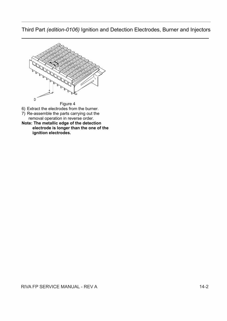
Figure 35) Unscrew the screws D (Figure 4) which hold
the electrodes to the burner.
Ignition and Detection Electrodes,Burner and Injectors
1) Function2) Checks3) Removal
RIVA FP SERVICE MANUAL - REV A 14-1
___________________________________________________________________________________________________
Third Part (edition-0106) Ignition and Detection Electrodes, Burner and Injectors_______________________________________________________________
DFigure 4
6) Extract the electrodes from the burner.7) Re-assemble the parts carrying out the
removal operation in reverse order.Note: The metallic edge of the detection
electrode is longer than the one of theignition electrodes.
RIVA FP SERVICE MANUAL - REV A 14-2

___________________________________________________________________________________________________
Third Part (edition-0106) Safety Thermostat_______________________________________________________________
1 Function
The safety thermostat A in Figure 1 is a devicethat senses the temperature of the primary circuitwater which flows in the outlet pipe of the primaryheat exchanger.If the temperature control system of the boilerfails and the temperature of the primary circuitreaches a dangerous temperature, the safetythermostat opens the electric circuit that suppliesthe on-off operators of the gas valve.Consequently, the full sequence ignition deviceattempts to light the burner and, at the end, locksthe boiler and lights the lock-out signal lamp.
A
Figure 1 2 Checks
A Overheat temperature value1) Set the temp. control knob to its maximum
position and run the boiler.
2) Allow the boiler to reach its maximumoperating temperature (monitor thetemperature gauge on the instrument panel).The boiler should maintain a temperaturebelow that of the safety thermostat and nooverheat intervention should occur.
Warning: Isolate the boiler from the mainselectricity supply before removingany covering or component.
B Electrical function1) Remove all the case panels and the lid of the
sealed chamber.2) Disconnect the safety thermostat and check
its electrical function. Normally (nointervention) the contact must be closed(electrical resistance zero Ω).
3 Removal
Warning: Isolate the boiler from the mainselectricity supply before removingany covering or component.
1) Remove all the case panels and the lid of thesealed chamber.
2) Unscrew the three screws B (Figure 2).
B
Figure 23) Disconnect the three connectors of the safety
thermostat.4) Remove the probe holder spring C freeing the
safety probe D (Figure 3).
Safety Thermostat
1) Function2) Checks3) Removal
RIVA FP SERVICE MANUAL - REV A 15-1

___________________________________________________________________________________________________
Third Part (edition-0106) Safety Thermostat_______________________________________________________________
C
D
Figure 35) Re-assemble the parts carrying out the
removal operation in reverse order.6) Apply an adequate quantity of heat conducting
compound between the pipe and thethermostat.
RIVA FP SERVICE MANUAL - REV A 15-2

___________________________________________________________________________________________________
Third Part (edition-0106) Electric Resistances_______________________________________________________________
Resume of the electric resistances in Ω of theboiler parts.
1 Pump Resistance
Figure 1Pump Resistance = 51.7 Ω.
2 Gas Valve Resistance
114 Ω
Figure 2
On-off operatorapprox. 1 122 Ω*
* at ambient temperatureFigure 5
3 Temperature Probe NTC Resistance
Figure 3
4 Fan Resistance
7.2 Ω
Figure 4
Electric Resistances
1) Pump Resistance2) Gas Valve Resistance3) Temperature Probe NTC Resistance4) Fan Resistance
RIVA FP SERVICE MANUAL - REV A 16-1
___________________________________________________________________________________________________
Third Part (edition-0106) Short Spare Parts List_______________________________________________________________
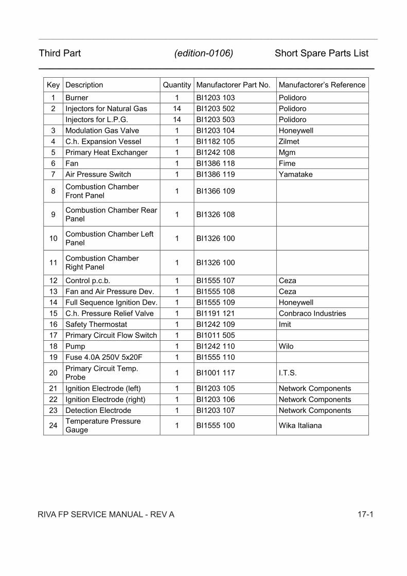
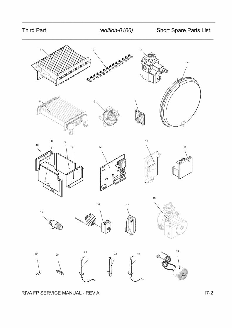
Key Description Quantity Manufactorer Part No. Manufactorers Reference1 Burner 1 BI1203 103 Polidoro2 Injectors for Natural Gas 14 BI1203 502 Polidoro
Injectors for L.P.G. 14 BI1203 503 Polidoro3 Modulation Gas Valve 1 BI1203 104 Honeywell4 C.h. Expansion Vessel 1 BI1182 105 Zilmet5 Primary Heat Exchanger 1 BI1242 108 Mgm6 Fan 1 BI1386 118 Fime7 Air Pressure Switch 1 BI1386 119 Yamatake
8 Combustion ChamberFront Panel 1 BI1366 109
9 Combustion Chamber RearPanel 1 BI1326 108
10 Combustion Chamber LeftPanel 1 BI1326 100
11 Combustion ChamberRight Panel 1 BI1326 100
12 Control p.c.b. 1 BI1555 107 Ceza13 Fan and Air Pressure Dev. 1 BI1555 108 Ceza14 Full Sequence Ignition Dev. 1 BI1555 109 Honeywell15 C.h. Pressure Relief Valve 1 BI1191 121 Conbraco Industries16 Safety Thermostat 1 BI1242 109 Imit17 Primary Circuit Flow Switch 1 BI1011 50518 Pump 1 BI1242 110 Wilo19 Fuse 4.0A 250V 5x20F 1 BI1555 110
20 Primary Circuit Temp.Probe 1 BI1001 117 I.T.S.
21 Ignition Electrode (left) 1 BI1203 105 Network Components22 Ignition Electrode (right) 1 BI1203 106 Network Components23 Detection Electrode 1 BI1203 107 Network Components
24 Temperature PressureGauge 1 BI1555 100 Wika Italiana
RIVA FP SERVICE MANUAL - REV A 17-1
___________________________________________________________________________________________________
Third Part (edition-0106) Short Spare Parts List_______________________________________________________________
12
1 2 3
5 6 7
4
8
16
10
2021 22
24
15
17
23
13
1411
18
19
9
RIVA FP SERVICE MANUAL - REV A 17-2

_______________________________________________________________________________________ ____________
(edition-0106) _______________________________________________________________
RIVA FP SERVICE MANUAL REV A