Embed Size (px)
Citation preview
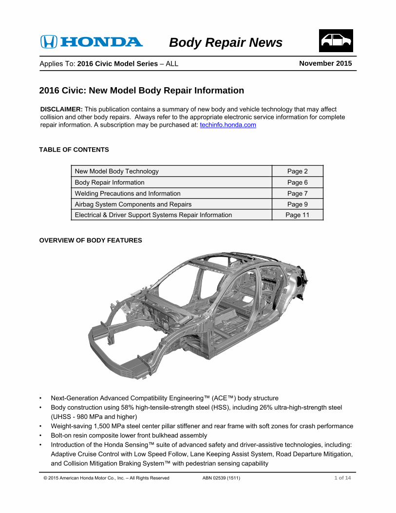
OVERVIEW OF BODY FEATURES
• Next-Generation Advanced Compatibility Engineering™ (ACE™) body structure
• Body construction using 58% high-tensile-strength steel (HSS), including 26% ultra-high-strength steel
(UHSS - 980 MPa and higher)
• Weight-saving 1,500 MPa steel center pillar stiffener and rear frame with soft zones for crash performance
• Bolt-on resin composite lower front bulkhead assembly
• Introduction of the Honda Sensing™ suite of advanced safety and driver-assistive technologies, including:
Adaptive Cruise Control with Low Speed Follow, Lane Keeping Assist System, Road Departure Mitigation,
and Collision Mitigation Braking System™ with pedestrian sensing capability
DISCLAIMER: This publication contains a summary of new body and vehicle technology that may affect collision and other body repairs. Always refer to the appropriate electronic service information for complete repair information. A subscription may be purchased at: techinfo.honda.com
Applies To: 2016 Civic Model Series – ALL
Body Repair NewsNovember 2015
2016 Civic: New Model Body Repair Information
TABLE OF CONTENTS
1 of 14
New Model Body Technology Page 2
Body Repair Information Page 6
Welding Precautions and Information Page 7
Airbag System Components and Repairs Page 9
Electrical & Driver Support Systems Repair Information Page 11
© 2015 American Honda Motor Co., Inc. – All Rights Reserved ABN 02539 (1511)
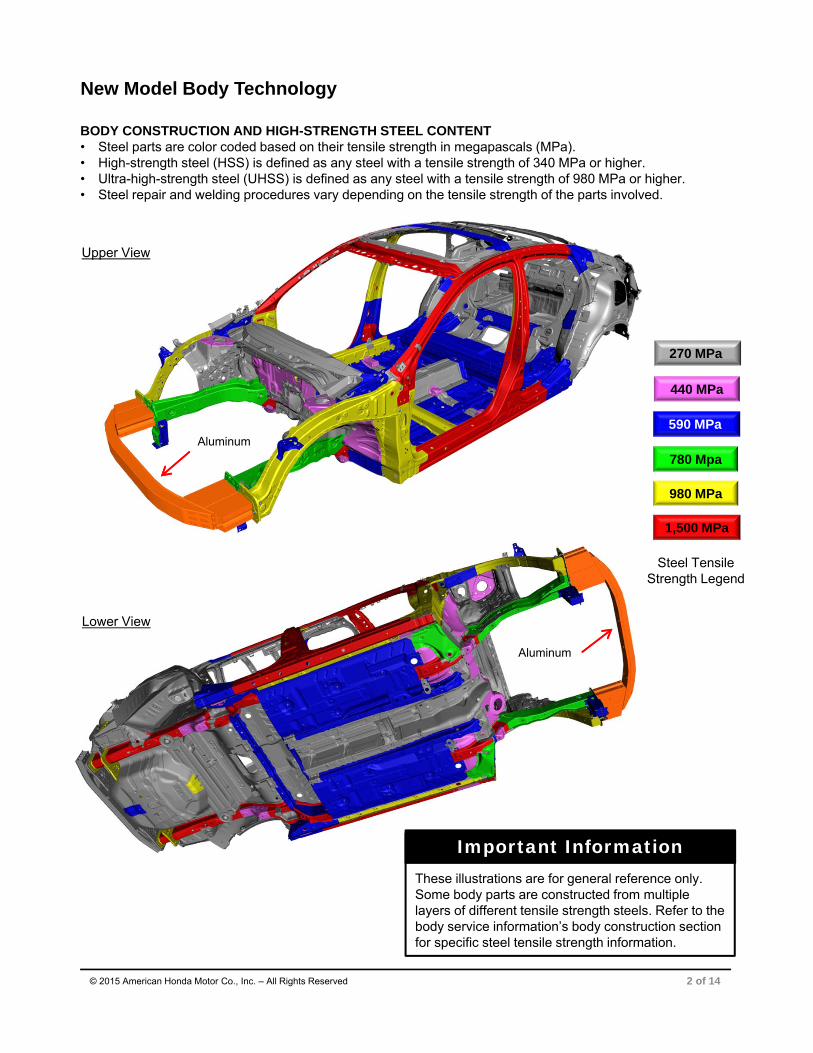
Lower View
Aluminum
Upper View
Aluminum
BODY CONSTRUCTION AND HIGH-STRENGTH STEEL CONTENT • Steel parts are color coded based on their tensile strength in megapascals (MPa). • High-strength steel (HSS) is defined as any steel with a tensile strength of 340 MPa or higher.• Ultra-high-strength steel (UHSS) is defined as any steel with a tensile strength of 980 MPa or higher.• Steel repair and welding procedures vary depending on the tensile strength of the parts involved.
2 of 14
New Model Body Technology
© 2015 American Honda Motor Co., Inc. – All Rights Reserved
980 MPa
590 MPa
440 MPa
1,500 MPa
780 Mpa
270 MPa
Steel Tensile Strength Legend
These illustrations are for general reference only. Some body parts are constructed from multiple layers of different tensile strength steels. Refer to the body service information’s body construction section for specific steel tensile strength information.
Important Information
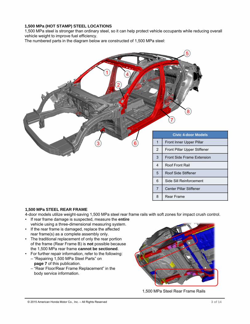
1,500 MPa STEEL REAR FRAME4-door models utilize weight-saving 1,500 MPa steel rear frame rails with soft zones for impact crush control. • If rear frame damage is suspected, measure the entire
vehicle using a three-dimensional measuring system.• If the rear frame is damaged, replace the affected
rear frame(s) as a complete assembly only. • The traditional replacement of only the rear portion
of the frame (Rear Frame B) is not possible because the 1,500 MPa rear frame cannot be sectioned.
• For further repair information, refer to the following:– “Repairing 1,500 MPa Steel Parts” on
page 7 of this publication.– “Rear Floor/Rear Frame Replacement” in the
body service information.
© 2015 American Honda Motor Co., Inc. – All Rights Reserved
1,500 MPa (HOT STAMP) STEEL LOCATIONS 1,500 MPa steel is stronger than ordinary steel, so it can help protect vehicle occupants while reducing overall vehicle weight to improve fuel efficiency.The numbered parts in the diagram below are constructed of 1,500 MPa steel:
1
2
3
4
5
7
6
8
Civic 4-door Models
1 Front Inner Upper Pillar
2 Front Pillar Upper Stiffener
3 Front Side Frame Extension
4 Roof Front Rail
5 Roof Side Stiffener
6 Side Sill Reinforcement
7 Center Pillar Stiffener
8 Rear Frame
1,500 MPa Steel Rear Frame Rails
3 of 14

ALUMINUM PARTS & REPAIRABILITY The front bumper beam uses 6000 series aluminum alloy construction.
Repairability Issues• Do not repair damaged bumper beams. • To help prevent galvanic corrosion, some
fasteners for aluminum parts are considered one-time use and must be replaced if removed.
4 of 14© 2015 American Honda Motor Co., Inc. – All Rights Reserved
Front Bumper Beam
RESIN COMPOSITE FRONT BULKHEADThis vehicle has a lower bulkhead assembly constructed of resin composite material.• The upper bulkhead frame is constructed of 270 MPa
mild steel. • The front upper and lower bulkheads are only sold
as a complete assembly. • The bulkhead design improves engine compartment
access during factory assembly and service. • The cooling fans, radiator, A/C condenser, hood lock,
outside air temperature sensor, and related piping/components are attached to the front bulkhead.
• The bulkhead is attached to the body with 20 bolts. • A damaged bulkhead must be replaced. • For more information, refer to “Front Bulkhead
Replacement” in the body service information.
FRONT BRACE COLLAR BOLTSThis front brace is located under the front bumper directly ahead of the front subframe.• The front brace is attached to the body using special
collar bolts that compensate for body dimensional variations. • A special removal and installation procedure is required• For more information, refer to “Front Brace Removal
and Installation” in the service information.
Resin Composite Front Bulkhead
Upper Bulkhead
LowerBulkhead
5 of 14© 2015 American Honda Motor Co., Inc. – All Rights Reserved
TOWING AND LIFTING PRECAUTIONS• Flat bed towing equipment is the preferred method to
transport this vehicle.• Front wheel lift towing equipment may also be used
to tow this vehicle.For more information, refer to “Emergency Towing” in the owner’s guide or service information. • Lift or jack only at the specified points to avoid damaging
the vehicle.• Do not lift or tow this vehicle by its bumpers, or serious
damage will result.For more information, refer to “Lift and Support Points” in the service information.
CAPLESS FUELING SYSTEMThis vehicle uses a capless fueling system. It does not have a conventional fuel fill cap.• A backup fuel door open cable is located under the parcel shelf.• If you need to refuel the vehicle from a portable fuel container,
a funnel is located in the trunk’s spare tire well tool case. • The fueling system can be damaged by directly inserting the
nozzle of a portable fuel container or by using any funnel other than the one provided with the vehicle.
• For more information, refer to “Refueling From a Portable Fuel Container” in the owner’s guide.
Capless Fueling System
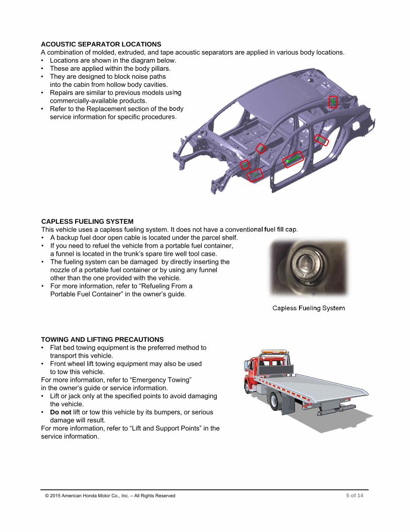
ACOUSTIC SEPARATOR LOCATIONS A combination of molded, extruded, and tape acoustic separators are applied in various body locations. • Locations are shown in the diagram below.• These are applied within the body pillars.• They are designed to block noise paths
into the cabin from hollow body cavities.• Repairs are similar to previous models using
commercially-available products. • Refer to the Replacement section of the body
service information for specific procedures.

Sectioning Area Examples
6 of 14
Body Repair Information
© 2015 American Honda Motor Co., Inc. – All Rights Reserved
USE OF HEAT DURING BODY STRAIGHTENING AND REPAIRWhen you are doing body straightening and repair procedures,follow these guidelines: • Do not apply heat to any body part during straightening.
This may compromise the internal structure and strength of high-strength steel parts.
• Any part that has heat applied to it during straightening must be replaced with new parts.
• Ignoring these instructions may significantly reduce occupant protection in any subsequent collision.
SECTIONING (CUT AND JOINT) GUIDELINES Various high-strength steel materials with different sheet thicknesses and strengths are applied in many places that vary by body design in order to increase collision safety performance, body stiffness, and weight reduction. Stiffening members inside each part (patch, stiffener, etc.) are also specified in detail.
Follow these guidelines to avoid an unsafe repair:• Sectioning (cut and joint) should usually be avoided except
for mild steel outer panels and floor panels unless a specific procedure is provided in the body service information.
• However, depending on the type of vehicle damage, steel parts with a tensile strength ≤ 780 MPa may besectioned provided all of the following conditions are met:– Sectioning must be done in a single-layer area of the part.– Multi-layer internal steel reinforcements and stiffeners
must not be cut.– The repair is not in a load-bearing area such as engine,
transmission, or suspension mounting points.• Replace body structural components such as
stiffeners, reinforcements, and other multi-layeredsteel parts as assemblies that match the replacementparts configuration.
• Approved welding methods are listed in the table on the right.
• Refer to the body service information for complete information.
NOTE: The following content is intended only to highlight new/special concerns. No body repairs should be attempted without first referencing the appropriate body service information.
Steel PartTensile Strength
(MPa)
Welding Method
SpotWeld
MAG Welding
Plug Butt
<590
590
780
980 X
1500 X X
Welding Methods for Steel Parts( = Approved X = Not Approved)
Do not heat during straightening

7 of 14© 2015 American Honda Motor Co., Inc. – All Rights Reserved
MIG BRAZING GUIDELINES FOR 1,500 MPa STEEL PARTSRefer to the body service information for complete procedures. • MIG-brazed joint locations are specified in the
body service information.• A single- or double-hole MIG braze may be
specified in the body service information depending on the tensile strength of the parts being joined.
• The size and number of holes are critical to achieving adequate joint strength.
• A MIG welder with pulse control must be used. Refer to the equipment manufacturer’s instructions for welder voltage and current setup.
• The photos on the right show the difference in results between pulsed and non-pulsed MIG brazing.
Welding Precautions and Information
REPAIRING 1,500 MPa STEEL PARTSObserve these precautions when repairing 1,500 MPa steel parts:• Never attempt to straighten damaged 1,500 MPa
steel parts; they may crack.• 1,500 MPa steel parts must be replaced at factory
seams using squeeze-type resistance spot welding (STRSW). Do not section these parts!
• MIG brazed joints should be used only in locations not accessible by a spot welder.
• To assure adequate weld tensile strength, always manually set the spot welder to the specifications provided in the body service information.
• Never do MAG welding on 1,500 MPa steel. The heat generated during MAG welding will significantly reduce the strength and structural integrity of 1,500 MPa steel parts.
• The photo on the right shows tensile strength test results of MAG welded 1,500 MPa steel. The 1,500 MPa steel fractured first because the welding heat reduced its strength to far below 590 MPa.
• For more details, refer to the body service information “Basic Welding Information” section.
Parts made of Ultra-High-Strength Steel (UHSS/1,500MPa/USIBOR) must be installed as a complete part. No sectioning is allowed. Ultra-High-Strength Steel requires special welding equipment, procedures, and settings. See the welding section of the body service information. Failure to use the proper equipment or follow the proper procedures can result in an unsafe repair.
Important Information
590 MPa 1,500 MPa
Tensile Test Results of MAG-Welded 1,500 MPa Steel
Pulsed MIG (OK) w/o Pulsed MIG (NG)

MAG WELDING SPECIFICATIONS FOR 590–980 MPa HIGH-STRENGTH STEEL PARTSNOTE: In this publication and the body service information, gas metal arc welding (GMAW) is referred to by its subtypes depending on requirements as follows:• MIG welding/brazing = Metal inert gas welding or
brazing where 100% argon (Ar) shielding gas is used. Argon is inert and does not react with the molten weld pool or brazing operation.
• MAG welding = Metal active gas welding where the shielding gas being used contains a mixture of 80% argon (Ar) and 20% carbon dioxide (CO2). It is considered active because the CO2 undergoes a limited reaction with the molten weld pool.
• For MAG welding, 80/20 shielding gas (C20) is preferred. However, 75/25 (C25) is acceptable
The body service information specifies the weld types and locations for each body panel as follows: • The welding wire used must have a tensile strength equal
to or greater than the lowest tensile strength of the parts being welded. The conversion chart on the right shows the relationship of steel tensile strength (MPa) to the minimum welding wire tensile strength (ksi).
• Typical ER70S-6 MIG wire has a minimum tensile strength of 70 ksi (483 MPa). It can be used when welding up to 440 MPa steel parts. Refer to the diagrams shown below:
Steel Tensile (MPa) Wire Tensile (ksi)
590 ≥86
780 ≥113
980 ≥142
(1,000 psi = 1 ksi)
8 of 14
Parts made of High-Strength Steel (590-980 MPa) must often be installed as a complete part. Section only according to published repair information and guidelines. This high-strength steel requires special welding equipment, procedures, and settings. See the welding section of the body service information. Failure to use the proper equipment or follow the proper procedures can result in an unsafe repair.
Important Information
© 2015 American Honda Motor Co., Inc. – All Rights Reserved
MAG PLUG WELDING GUIDELINES • MAG plug welding may be done when joining body
components to 590–980 MPa steel parts. • Follow the recommendations described in the body
service information “Basic Welding Information” section.
MAG BUTT WELDING GUIDELINES • MAG butt welding may be done only on steel parts
with a tensile strength of 780 MPa and lower. • Welding speed is critical to achieve the correct weld
strength and minimize the heat affected zone (HAZ).• Follow the recommendations described in the body
service information “Basic Welding Information” section.
590 Mpa Steel
980 Mpa Steel
Wire tensile strength must be ≥590 MPa (86 ksi)
MAG Plug Welds
Wire tensile strength must be ≥590 MPa (86 ksi)
MAG Butt Welds
590 Mpa Steel 590 Mpa Steel
SmartVent Side Airbag
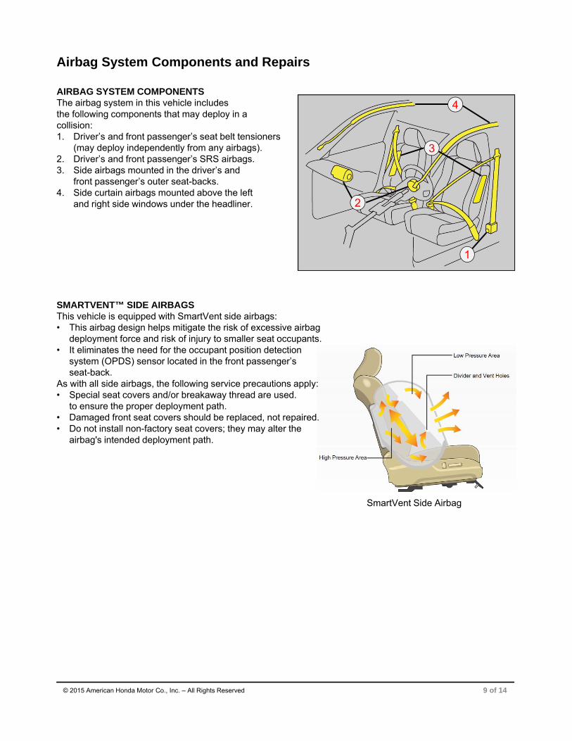
AIRBAG SYSTEM COMPONENTSThe airbag system in this vehicle includes the following components that may deploy in a collision:1. Driver’s and front passenger’s seat belt tensioners
(may deploy independently from any airbags). 2. Driver’s and front passenger’s SRS airbags.3. Side airbags mounted in the driver’s and
front passenger’s outer seat-backs.4. Side curtain airbags mounted above the left
and right side windows under the headliner.
SMARTVENT™ SIDE AIRBAGSThis vehicle is equipped with SmartVent side airbags: • This airbag design helps mitigate the risk of excessive airbag
deployment force and risk of injury to smaller seat occupants.• It eliminates the need for the occupant position detection
system (OPDS) sensor located in the front passenger’s seat-back.
As with all side airbags, the following service precautions apply:• Special seat covers and/or breakaway thread are used.
to ensure the proper deployment path. • Damaged front seat covers should be replaced, not repaired.• Do not install non-factory seat covers; they may alter the
airbag's intended deployment path.
9 of 14
Airbag System Components and Repairs
© 2015 American Honda Motor Co., Inc. – All Rights Reserved
3
4
2
1

10 of 14© 2015 American Honda Motor Co., Inc. – All Rights Reserved
AIRBAG SYSTEM ELECTRICAL REPAIRSExcept when doing electrical inspections that require battery power, always turn the ignition to OFF,disconnect the negative battery cable, then wait at least 3 minutes before starting work. • For easier identification, electrical connectors that contain only
airbag system wiring are yellow in color. • Many harnesses that contain primarily airbag wiring are also
wrapped in yellow tape. • Airbag system wiring that runs in a common harness, such as a
floor harness, is generally not marked. • Never attempt to modify, splice, or repair airbag system wiring.
If any part of the airbag system wiring is damaged, replace the affected wiring harness(es).
NOTE: Refer to the service information for complete restraint systems operation, diagnostic, and repair information.
AIRBAG SYSTEM INDICATORSThere are two indicators used for the airbag system.
Supplemental Restraint System (SRS) IndicatorWhen you turn the ignition to ON, this indicator should come on and then turn off after about 6 seconds. • If the SRS indicator does not go off or does not come on at all,
there is a problem with the system.• DTCs must be read and cleared using the HDS (or equivalent)
scan tool. Contact a Honda dealer for assistance if necessary. • If a vehicle is sent to the dealer for airbag system repair or
troubleshooting, include a copy of the repair estimate with part numbers and the source for any replaced airbag system parts.
PASSENGER AIRBAG OFF IndicatorThe indicator comes on to alert you that the passenger’s front airbag has been turned off.• This occurs when the front passenger’s seat weight sensors
detect about 65 lb. (29 kg) or less, the weight of an infant or small child on the seat.
• Unlike previous Honda models, this indicator stays on when the front passenger’s seat is empty. This is due to a design change in the front passenger’s seat weight sensors.
AIRBAG SYSTEM REPAIRS REQUIRED AFTER DEPLOYMENTTo restore proper function and allow DTCs to be cleared, the airbag system must be repaired as specified in the service information. Refer to “Component Replacement/Inspection After Deployment” for complete information. • Do not install used, refurbished, or modified airbag system parts! • When making airbag system repairs, only use new genuine Honda replacement parts, which are
manufactured to the same standards and quality as the original parts.• To ensure the correct replacement airbag system parts are installed, provide the VIN when ordering parts.
Compare the part numbers on the new and removed parts to make sure they match.• The front passenger’s seat weight sensor must be initialized with the HDS under these conditions:
– The SRS unit is replaced– The front passenger's seat, seat frame, weight sensor, and/or seat rail is removed or replaced
• For more information, refer to “Front Passenger's Weight Sensor Initialization” in the service information.
SRS Indicator
PASSENGER AIRBAG OFF Indicator
11 of 14
Electrical & Driver Support Systems Repair Information
© 2015 American Honda Motor Co., Inc. – All Rights Reserved
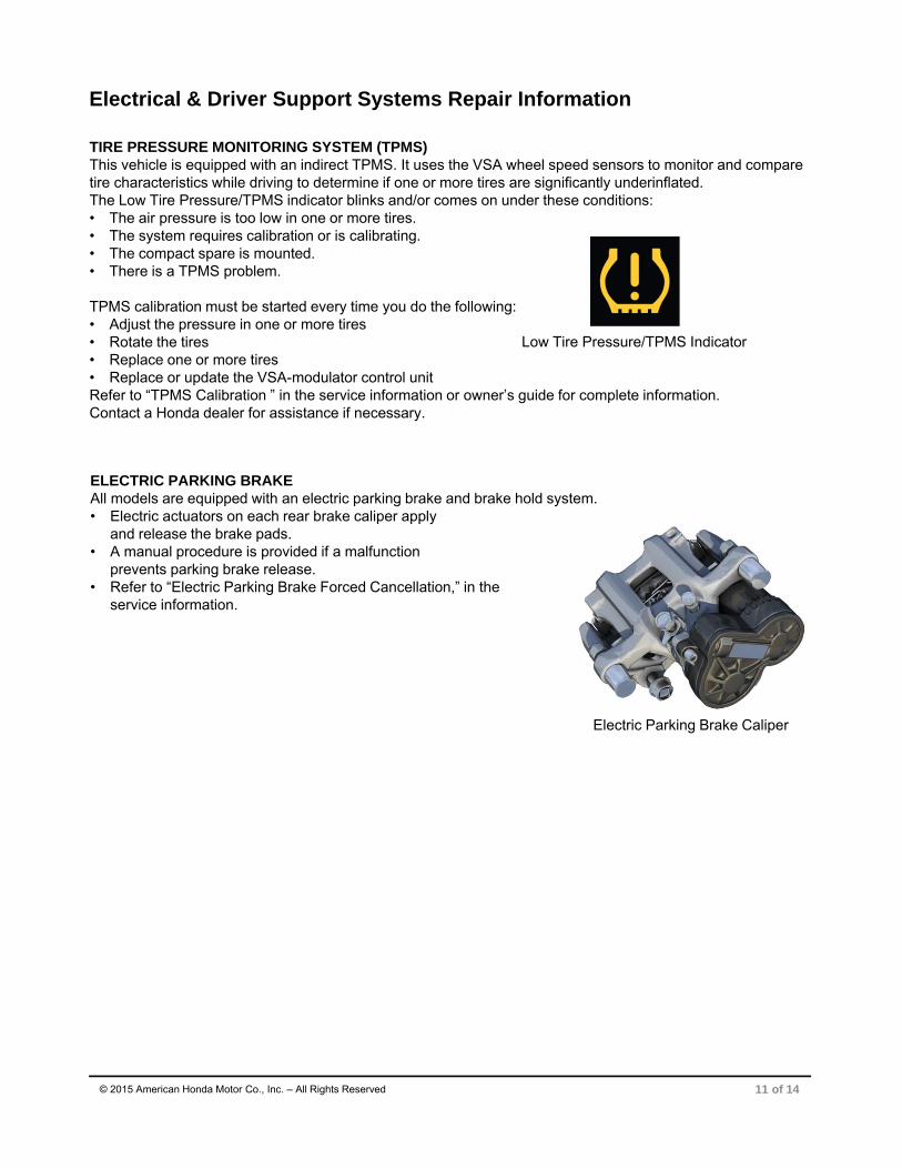
TIRE PRESSURE MONITORING SYSTEM (TPMS)This vehicle is equipped with an indirect TPMS. It uses the VSA wheel speed sensors to monitor and compare tire characteristics while driving to determine if one or more tires are significantly underinflated.The Low Tire Pressure/TPMS indicator blinks and/or comes on under these conditions: • The air pressure is too low in one or more tires. • The system requires calibration or is calibrating.• The compact spare is mounted.• There is a TPMS problem.
TPMS calibration must be started every time you do the following:• Adjust the pressure in one or more tires• Rotate the tires• Replace one or more tires• Replace or update the VSA-modulator control unitRefer to “TPMS Calibration ” in the service information or owner’s guide for complete information. Contact a Honda dealer for assistance if necessary.
Low Tire Pressure/TPMS Indicator
ELECTRIC PARKING BRAKEAll models are equipped with an electric parking brake and brake hold system. • Electric actuators on each rear brake caliper apply
and release the brake pads. • A manual procedure is provided if a malfunction
prevents parking brake release. • Refer to “Electric Parking Brake Forced Cancellation,” in the
service information.
Electric Parking Brake Caliper

12 of 14© 2015 American Honda Motor Co., Inc. – All Rights Reserved
SYSTEMS THAT MAY REQUIRE DEALER ASSISTANCE WITH AIMING Some models may be equipped with one or more of the following systems that require aiming after collision repairs. Special tools are required to complete the aiming procedures. Contact a Honda dealer for assistance.
Forward Collision Warning and Lane Departure Warning (FCW/LDW):The multipurpose camera unit must be re-aimed in these instances: • The camera unit is removed or replaced.• The windshield is removed or replaced. If the aiming is incomplete, the Forward collision warning and Lane departure warning indicators will come on and blink. Forward collision warning and Lane departure warning messages may also appear.
Adaptive Cruise Control (ACC) and Collision Mitigation Braking System™ (CMBS™):The millimeter wave radar for the ACC/CMBS must be re-aimed in these instances :• The radar unit is removed or replaced.• The radar unit’s mounting area was damaged.• If the aiming process is not completed, or the procedure
in the service information is not followed, the ACC indicator changes to amber and a message may also appear.
Lane Keeping Assist System (LKAS):The multipurpose camera unit must be re-aimed in these instances: • The camera/control unit is removed or replaced.• The windshield is removed or replaced. • If the aiming is not done or is not completed, the LKAS indicator
changes to amber and blinks. A message may also appear.
Windshield Replacement On FCW/LDW/LKAS-Equipped Vehicles:• Windshield damage within the multipurpose camera unit’s field
of vision can cause any of these systems to operate abnormally. • Only a genuine Honda replacement windshield should be installed. Installing
an aftermarket replacement windshield may also cause abnormal operation.
Forward Collision Warning/Collision Mitigation Braking System Indicator
Lane Departure Warning Indicator
NOTE: Appearance of messages on the vehicle may vary slightly
HVAC SYSTEM AND R-1234yf A/C REFRIGERANTThis vehicle’s A/C system uses the more environmentally-responsible R-1234yf refrigerant.• R-1234yf refrigerant is considered “mildly flammable.”
Be sure to observe all basic safety precautions for working around flammable gases. Refer to “A/C Service Tips and Precautions” in the service information.
• The system should only be serviced by qualified A/C technicians trained to handle R-1234yf refrigerant.
• Refrigerant recovery, charging, and leak detection all require dedicated tools and equipment designed and SAE approved for use with R-1234yf.
• Honda dealers have this equipment. Please contact your local dealer if you need assistance.
• RL85HM POE refrigerant oil is used in this A/C system. Do not use any other type of refrigerant oil.
• The receiver/dryer is integrated into the A/C condenser assembly and cannot be replaced separately.
• The receiver/dryer’s desiccant bag is serviceable separately.
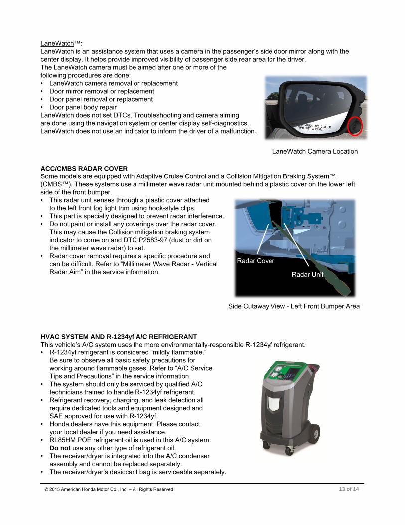
LaneWatch™:LaneWatch is an assistance system that uses a camera in the passenger’s side door mirror along with the center display. It helps provide improved visibility of passenger side rear area for the driver.The LaneWatch camera must be aimed after one or more of the following procedures are done: • LaneWatch camera removal or replacement• Door mirror removal or replacement• Door panel removal or replacement• Door panel body repairLaneWatch does not set DTCs. Troubleshooting and camera aiming are done using the navigation system or center display self-diagnostics. LaneWatch does not use an indicator to inform the driver of a malfunction.
13 of 14© 2015 American Honda Motor Co., Inc. – All Rights Reserved
ACC/CMBS RADAR COVERSome models are equipped with Adaptive Cruise Control and a Collision Mitigation Braking System™ (CMBS™). These systems use a millimeter wave radar unit mounted behind a plastic cover on the lower left side of the front bumper. • This radar unit senses through a plastic cover attached
to the left front fog light trim using hook-style clips. • This part is specially designed to prevent radar interference. • Do not paint or install any coverings over the radar cover.
This may cause the Collision mitigation braking system indicator to come on and DTC P2583-97 (dust or dirt on the millimeter wave radar) to set.
• Radar cover removal requires a specific procedure and can be difficult. Refer to “Millimeter Wave Radar - Vertical Radar Aim” in the service information.
Side Cutaway View - Left Front Bumper Area
Radar Unit
Radar Cover
LaneWatch Camera Location

ELECTRICAL PIGTAIL AND CONNECTOR REPAIR• Disconnect the vehicle’s battery before doing any
welding or electrical repairs. Refer to “12 Volt Battery Terminal Disconnection and Reconnection” in the service information.
• Certain front and rear electrical connectors subject to collision damage may be repaired using pigtails and connectors listed in the ELECTRICAL CONNECTORS illustrations in the parts catalog (example shown here).
• Pigtails attach to the vehicle wiring using special crimp-and-seal terminal joints. After crimping, the jointsare heated using a heat gun to seal out the environment.
• Repair pigtails come in a limited range of colors that usually do not match the vehicle’s wiring. Pay close attention during repairs to ensure correct locations.
• Vehicle wiring schematics service information can be found in the electrical wiring diagrams (EWD).
• If wiring is damaged and a repair pigtail or connector is not available, replace the affected harness.
• Never attempt to modify, splice, or repair airbag system wiring.
ELECTRICAL GROUNDS & PROTECTION Failure to protect ground locations is the #1 cause of post-collision electrical problems on our vehicles.• Painting over electrical ground locations may cause
electrical systems, such as vehicle stability assist (VSA), to malfunction and set DTCs that may be difficult to diagnose.
• Protect the ground wire with masking tape and the ground wire mounting hole threads with a bolt or silicone plug when priming or painting.
• Honda ground bolts are almost always non-anodized, zinc plated self-cutting bolts. They can be identified by the triangular notch in the threads. Using the wrong bolt can cause ground problems.
• Do not use star or burred washers on electrical grounds.
14 of 14© 2015 American Honda Motor Co., Inc. – All Rights Reserved