Embed Size (px)
Citation preview

© 2012 Eaton Corporation. All rights reserved.
Bob Ruzensky
Regional Sales Director – Gulf Region

2© 2013 Eaton, All Rights Reserved.
Agenda
• Peak Transformers
• VFI Protected Transformers
• Addressing Arc Flash when doing preventive
maintenance on transformers

3© 2013 Eaton, All Rights Reserved.
A NEW ERA IN TRANSFORMER DESIGN

44
• High Fire-Point
• Mineral Oil: 155°C
• EnvirotempTM FR3TM: ≈360°C
• Non-Toxic
• Renewable
4
Envirotemp™ FR3™ Fluid
PEAK Transformers Include all the Benefits of Envirotemp™ FR3™ Fluid
Envirotemp™ and FR3™ are licensed trademarks of Cargill, Incorporated.

55
Transformer Customer Challenges
5
Electrical Consumption and Demand are Growing
Load Growth and Future Demand May Stress Transformers Beyond Nameplate Ratings− Some Loads are Variable
− Some Load are Predictable
Some Projects Have Size and Weight Constraints for Transformers
Customers Prefer Flexibility in Loading Transformers
PEAKTM Transformers May Be Part of the Solution

66
PEAK Transformer Family
6Envirotemp™ and FR3™ are licensed trademarks of Cargill, Incorporated.
PEAK transformers from Cooper Power Systems are designed to:
Provide enhanced capability compared to traditional transformers in
today’s market
Utilizes an advanced high temperature insulation system
Thermally upgraded kraft paper
EnvirotempTM FR3TM dielectric fluid
Optimized core and coil design.

77
PEAK Transformers – Three Options
1. Increased Overload Capacity
• PEAK 65/75 ⁰C Average Winding Rise (AWR)
• Operate PEAK transformers beyond full rated base
load
• Single-phase at least 9%
• Three-phase at least 12%
7Envirotemp™ and FR3™ are licensed trademarks of Cargill, Incorporated.

88
PEAK Transformers – Three Options
1. Increased Overload Capacity
• PEAK 65/75 ⁰C Average Winding Rise (AWR)
• Operate PEAK transformers beyond full rated base
load
• Single-phase at least 9%
• Three-phase at least 12%
• More precisely size transformers based on periods
of peak demand—without accelerated reduction of
insulation life
8Envirotemp™ and FR3™ are licensed trademarks of Cargill, Incorporated.

99
PEAK Transformers – Three Options
1. Increased Overload Capacity
• PEAK 65/75 ⁰C Average Winding Rise (AWR)
• Operate PEAK transformers beyond full rated base
load
• Single-phase at least 9%
• Three-phase at least 12%
• More precisely size transformers based on periods
of peak demand—without accelerated reduction of
insulation life
• Continuous overload capabilities to
75⁰ C AWR
• Maintains IEEE® per unit life requirements at
75 ⁰ C AWR
• 65 °C AWR and 75 °C AWR kVA ratings
on the nameplate
9Envirotemp™ and FR3™ are licensed trademarks of Cargill, Incorporated.

1010
PEAK Transformers – Three Options
1. Increased Overload Capacity
• PEAK 65/75 ⁰C Average Winding Rise (AWR)
• Operate PEAK transformers beyond full rated base
load
• Single-phase at least 9%
• Three-phase at least 12%
• More precisely size transformers based on periods
of peak demand—without accelerated reduction of
insulation life
• Continuous overload capabilities to 75⁰ C AWR
• Maintains IEEE® per unit life requirements at 75 ⁰C AWR
• 65 °C AWR and 75 °C AWR kVA ratings
on the nameplate
• Complies with IEEE Std C57.154™-2012
standard
10Envirotemp™ and FR3™ are licensed trademarks of Cargill, Incorporated.

1111
PEAK Transformers – Three Options
2. Increased Overload Capacity
• PEAK 55/75 ⁰C Average Winding Rise (AWR)
• Operate PEAK transformers beyond full rated base
load
• Three-phase at least 22%
• More precisely size transformers based on periods
of peak demand—without accelerated reduction of
insulation life
• Continuous overload capabilities to 75⁰ C AWR
• Maintains IEEE® per unit life requirements at 75 ⁰C AWR
• 55 °C AWR and 75 °C AWR kVA ratings
on the nameplate
• Complies with IEEE Std C57.154™-2012
standard
11Envirotemp™ and FR3™ are licensed trademarks of Cargill, Incorporated.

1212
PEAK Transformers – Three Options
3. Smaller, Lighter Transformers
• PEAK 75 ⁰C Average Winding Rise
• Smaller and lighter than traditional 65 °C AWR
transformers of the same kVA rating
• Typically use less material and fewer gallons of
dielectric fluid
─resulting in better value
• Complies with IEEE Std C57.154™-2012
standard
• All PEAK Transformers are filled with
EnvirotempTM FR3TM Fluid
12Envirotemp™ and FR3™ are licensed trademarks of Cargill, Incorporated.

1313
Ideal for Expectation of Increasing Demand and for Withstand of Peak or Prolonged Overload Conditions
− Application: serve building with expectation of growth in tenants over time
• Eliminates need to replace transformer with larger kVA unit
Why Increased Overload Capacity?
13

1414
Ideal for Expectation of Increasing Demand and for Withstand of Peak or Prolonged Overload Conditions
− Application: Serve building with expectation of growth in tenants over time
• Eliminates need to replace transformer with larger kVA unit
− Application: Double-ended substation with shared load on each end capable of serving full load on one side for periods of time
Why Increased Overload Capacity?
14
1515
Ideal for Expectation of Increasing Demand and for Withstand of Peak or Prolonged Overload Conditions
− Application: serve building with expectation of growth in tenants over time
• Eliminates need to replace transformer with larger kVA unit
− Application: double-ended substation with shared load on each end capable of serving full load on one side for periods of time
− Application: for critical loads where overload is a concern, 65/75 °C AWR provides an alternative, or complementary, solution to forced air (fans) and transformer oversizing
Why Increased Overload Capacity?
15

1616
Increased Reliability
Aging of paper depends primarily on temperature and water content.
Paper Aged in Seed-Oil based fluid took 5-8 times longer to reach
end of life parameters than paper aged in Mineral Oil.
Longer Insulation System Life Than Conventional Mineral Oil-Filled Transformers

1717
FR3™ Fluid & Moisture
• Higher Moisture Content in Insulation than Fluid
FR3™ and Envirotemp™ are licensed trademarks of Cargill, Incorporated
1818
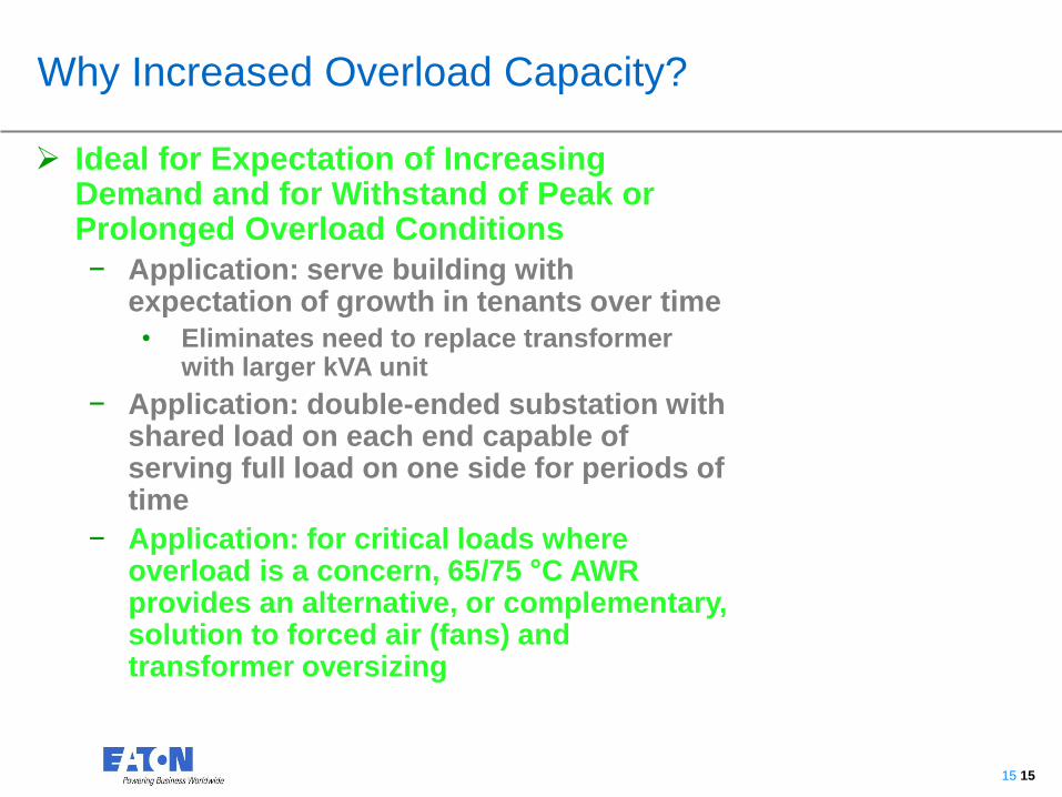
FR3™ Fluid & Moisture
• Higher Moisture Content in Insulation
• FR3™ - Higher Affinity for and Tolerance of Moisture
• 25 C Saturation Levels• Mineral Oil: 70 ppm
• EFR3™ : 1200 ppm
FR3™ and Envirotemp™ are licensed trademarks of Cargill, Incorporated

1919
FR3™ Fluid & Moisture
• Higher Moisture Content in Insulation
• FR3™ - Higher affinity for and tolerance of moisture
• 25 C Saturation Levels• Mineral Oil: 70 ppm
• FR3™ : 1200 ppm
• Maintains Dielectric Strength Similarly to Mineral Oil in Terms of Relative Saturation
FR3™ and Envirotemp™ are licensed trademarks of Cargill, Incorporated

2020
VFI Transformer

2121
Vacuum Fault Interrupter (VFI) Transformer
Switchgear Protection Inside a Transformer• Internal under-oil vacuum fault interrupter
• Three-phase gang operated
• Trip function through Tri-Phase Ground control w/ SCADA
- Gauge contacts wired into SCADA control
- Trip/open function only, won’t automatically reclose
• Optional Trip Function and Protection with Cooper IDEA Relays
• Optional Motor Operator for Remote Closure
• Optional contact switches are wired for alarm or control
functions outside transformer
• User defined schematic based on system requirements
Optional Motor Operator
Available on Pads & Substations

2222
VFI Transformer
• 3Ø Primary over-current
protection and switching
(Vacuum Fault Interrupter)
installed integral to
transformer.
• Resettable medium voltage
breaker with electronic
control
• Over 100 minimum trip
settings
Guentert, J. (2012). Protection, Arc Flash Mitigation Using VFI [Photograph]. CSE Magazine.

2323
VFI transformer
• Up to 35 kV rating
• 600 or 900 A continuous rating
• 12 kA & 16 kA interrupting rating
• Optional secondary relay
• Used to trip VFI on secondary
fault
• Helps mitigate secondary arc
flash hazards
Guentert, J. (2012). Protection, Arc Flash Mitigation Using VFI [Photograph]. CSE Magazine.

2424
TPG w/SCADA
Tri-Phase TPG (Tri-Phase w/Ground)
Standard VFI Controls

2525
VFI switchgear can be customized to be Smart-Grid Ready
• Equipped with iDEA Platform
Controls
• Remote open/close option
• Internal PTs/CTs for voltage
sensing
• Wide range of communication
options available with the
iDEA controls (Ethernet, Fiber
Optic, RS 485)
Smart-Grid ready VFI

2626
Improved System Coordination
• Improved Coordination with Other System Protective Equipment Eliminates Unnecessary Outages
• Tri-Phase Control Improves Coordination for Maximum Up-time
• Selectable TCC Curves
• Pickup Settings from 10-1290 A
• Instantaneous
• Ground Element
• Min Response Time Accessory
• Cold Load Pickup Capable
• SCADA Capable for Automation
Solves complex coordination problems

2727
• Switchgear-type over-
current protection for
large pad-mounted or
substation transformers
• Provides smallest
footprint for primary
switching and over-
current protection
VFI transformer
HV Duplex Load-break
Air Switches
Dry Transformer
Dual Feed Bushings
Selector Switch
VFI
Handle

2828
Visible break
VFI transformer w/ visible break
2929
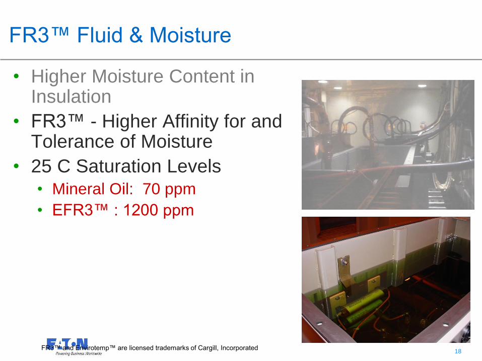
• Available in pad-mounted
design eliminating pad-
mounted switchgear
• VFI control in HV
termination compartment
Pad-mounted VFI transformer

3030
Complete 35kV Connector System
• Bushing
• Tee body
• Junctions
• 200 A tap plugs
• Insulating plugs
• Connector plugs
• Bushing extender
• 200 A caps
• 600 A caps
“200 kV BIL”
Product markings match 200 kV BIL
bushing color

3131
Voltage Ratings and Characteristics
3232
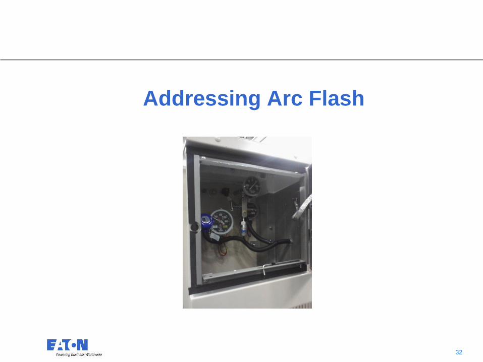
Addressing Arc Flash

3333
Addressing Arc Flash
IEEE C57.12.34 requires opening LV compartment door before accessing HV.

3434
Addressing Arc Flash
• Essential Monitoring
Equipment Accessible
Outside Termination
Compartments
• Drain Valve & Sampler
• Gages
• Load-break switches

3535
Addressing Arc Flash
• Externally operable visible
break switching
• Reduces unnecessary arc
flash exposure
• Improved visibility and safety
compared to standard load-
break switch mounting
• Ability to ground transformer
windings with on/off/ground
• Reduce maintenance costs
• Maintains tamper resistance

3636
Externally operated visible load-break switch
Visible break windowGages Load-break
switch handle

3737
Externally operated visible load-break switch

3838
Seismic
• OSHPD Certified.
• SDS
• Design spectral response acceleration
• Japanese earthquake SDS =1.0
• Cooper transformers certified to SDS = 1.93
• Manufacturers vary greatly in terms of kVA ratings being
OSHPD certified
• Transformers Will Also Comply With IBC Seismic
Requirements

3939
DOE defined benefits of 2016 standard
• Increased efficiency standards provide the following perceived national benefits over 30 year period• 3.63 quadrillion (1015) Btu of energy
• Roughly equivalent to the energy consumed by 40 million American households in one year
• 264.7 million metric tons (Mt) of carbon dioxide (CO2)• Average passenger car emits 4.75 metric tons
CO2E/vehicle/year• http://www.epa.gov/cleanenergy/energy-
resources/refs.html
• Roughly equivalent to removing over 55 million light duty passenger cars for one year
• 203.0 thousand metric tons of nitrogen oxides (NOX)
• 182.9 thousand metric tons of sulfur dioxide (SO2)
• 1,200 pounds of mercury (Hg)
Source: “Energy Efficiency Program For Certain Commercial And Industrial Equipment” 10 “CFR” 431.2

4040
0
2
4
6
8
10
12
14
16
18
20
15 30 45 75 112.5 150 225 300 500 750 1000 1500 2000 2500
Ineff
icie
ncy r
ed
ucti
on
(%
)
3-Ph kVA at DOE (50%) load
3-Phase liquid-filled: DOE 2010 vs. DOE 2016

4141
Impact of DOE 2016
• Transformer sizes, weights, and prices likely to
change
• Changes dependent upon specific customer
requirements and transformer type and rating
• General observations
• Core/coil weight increases are likely
• Footprint may change
• Eaton can design to meet dimensional constraints
The redesign process must be completed in order to provide firm size, weight,
and price changes

4242
Weight change example: 3-phase pad-mounted
Graph is representative of a subset of designs transitioning from DOE 2010 to DOE 2016.
Individual designs may have increases above or below averages presented above.
Transformers with high-current secondary's (i.e. 750kVA+, 208Y/120) will have weight increases well above average
0%
2%
4%
6%
8%
10%
12%
14%
16%
18%
20%
75 112.5 150 225 300 500 750 1000 1500 2000 2500
Av
era
ge W
eig
ht
Ch
an
ge
kVA

4343
kVA DOE 2010
Efficiency (%)
DOE 2016
Efficiency (%)
DOE 2010 Base
Losses (W)
DOE 2016 Base
Losses (W)
Change In
Base Losses
15 98.36 98.65 123 101 -18%
30 98.62 98.83 207 176 -15%
45 98.76 98.92 279 243 -13%
75 98.91 99.03 409 364 -11%
112.5 99.01 99.11 557 501 -10%
150 99.08 99.16 690 630 -9%
225 99.17 99.23 934 866 -7%
300 99.23 99.27 1155 1095 -5%
500 99.25 99.35 1875 1625 -13%
750 99.32 99.4 2550 2250 -12%
1000 99.36 99.43 3200 2850 -11%
1500 99.42 99.48 4350 3900 -10%
2000 99.46 99.51 5400 4900 -9%
2500 99.49 99.53 6375 5875 -8%
3-Phase liquid-immersed efficiency and base losses

4444
Think “MITS” for convenience
MITS – Modular Integrated Transportable
• Fully Integrated
• Factory-assembled, wired, and
tested to minimize on-site labor
costs, quality issues, and time
• Modular
• Flexible, and expandable design
allows a variety of equipment
configurations
• Transportable
• Structural base allows for
assembled units to be lifted and
transported, and relocated.

4545
Voltage Regulators
Single-phase or three-phase
Self contained
+/- 10% regulation
32 Steps, 5/8% increments
55/65 °C average winding rise
(12% more capacity)
25 to 2000 A
2400 V to 34500 V (60-200 BIL)
FR3 or Mineral Oil
Fan cooling option (33% more
capacity)
Substation, pole and pad-mounted
designs

4646
Success Story: Overhead Regulators
• Arizona mining customer having
power quality issues on their shovels
• Eaton CPS and EESS reps sold
benefit of Voltage Regulators over
Substation Load Tap Changers
(LTC’s) for power factor correction
• Minimum outage required for maintenance
• Regulation separate from main
transformer
• Lower Cost
• Designs optimized for the application
• Full 3 phase power quality monitoring
• Readily available replacements
• Communications integration and
automation

4747