Embed Size (px)
Citation preview
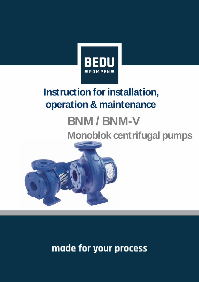
made for your process
Instruction for installation, operation & maintenance
BNM / BNM-V Monoblok centrifugal pumps

www.bedu.eu

i
Contents
CONTENTS iIDENTIFICATION OF SAFETY AND WARNING SYMBOLS iiiGENERAL INSTRUCTIONS iiiSAFETY INSTRUCTIONS iii
A- GENERAL 1A1- Pump Description 1A2- Applications 1A3- Pump Designation 1A4- Pump Nameplate 1A5- Technical Data 1
B- UNCRATING, TRANSPORT AND STORAGE 2B1- Uncrating 2
B2- Transport 2 B2.1- General recommendations 2 B2.2- Lifting 2B3- Storage 3
C- INSTALLATION ON SITE 3C1- Preparation For Installation 3
C2- Installation Site 3 C2.1- Foundation 3
C2.2- Installation 3 C3- Connection The Piping 4 C3.1- General 4 C3.2- Suction piping 4 C3.3- Discharge piping 4 C3.4- Auxiliary pipe connections and accessories 4 C3.5- Minimum flow 4 C3.6- Electrical connections 6 C3.7- Final check 7
D- START UP / SHUT DOWN 7 D1- Preparation 7
D1.1- Lubrication control 7 D1.2- Check the shaft seal 7
D1.3- Venting and priming 7 D1.4- Checking the direction of rotation 7 D2- Start Up The Pump 7 D3- Shut Down The Pump 8
D4- Checks To Be Made While The Pump Is Running 8
E- LUBRICATION 8
www.bedu.eu

ii
F- DISASSEMBLY, REPAIR AND REASSEMBLY 8F1- Disassembly 8
F2- Reassembly 9 F3- Shaft Seal 9
G- SPARE PARTS 10H- FAULTS, CAUSES AND REMEDIES 10I- TIGHTENING TORQUES 12J- EXPECTED NOISE VALUES 12K- PERMISSIBLE FORCES AND MOMENTS AT THE PUMP FLANGES 13L- PUMP DIMENSION GROUPS AND WEIGHTS 14M1- SECTIONAL DRAWINGS (VERTICAL INSTALLATION) 17M2- SECTIONAL DRAWINGS (FOR MOTOR FRAME SIZE UP TO 200) 18M3- SECTIONAL DRAWINGS (FOR MOTOR FRAME ABOVE 200) 19N- COUPLING GUARD AND SAFETY GUARD 20
www.bedu.eu

iii
ATTENTION
This manual is intended to be a reference guide for users of pumps providing information on
Pump installation and maintenance instructions,Pumps start-up, operation and shut - down procedures.
IDENTIFICATION OF SAFETY AND WARNING SYMBOLS Safety instructions in this manual which could cause danger to life if not observed.
The presence of a dangerous electric current.
Non – observance to this warning could damage the machine or affect its functions.
GENERAL INSTRUCTIONS
- This manual should be kept in a safe place and ALWAYS be available to the QUALIFIED operating and maintenance personnel responsible for the safe operation and maintenanceof the pumps.
- Qualified personnel should be experienced and knowledgeable of safety standards.- To avoid faulty operation and malfunctioning of pumps the instructions in this manual are to be CAREFULLYstudied and followed at all stages of the pump installation and operating life.- The user is responsible for ensuring that inspection and installation are carried out by authorized and qualifiedpersonnel who have studied this manual carefully.- The pump should be used ONLY in the operating conditions given on the order for which the pump andmaterials of the construction have been selected and tested.- If the pump is to be used for a different application please contact sales office or representative of themanufacturer. Bedu Pompen BV refuses to assume any responsibility if the pump used for different applicationswithout prior written permission.- If the pump is not to be installed and operated soon after arrival, it should be stored in a clean and dry placewith moderate changes in ambient temperature. Extreme low or high temperatures may severely damage thepump unless suitable precautions are taken. The user is responsible for the verification of the ambient conditionswhere the pump will be stored or installed.- Bedu Pompen BV does not guarantee repairs or alterations done by user or other unauthorized personnel.The use of original spare parts and accessories authorized by manufacturer will ensure safety.- This manual does not take into account any site safety regulation, which may apply.
SAFETY INSTRUCTIONS
Strictly obey to the following instructions to prevent personal injuries and/or equipment damages:
- Pump should be used only in the specified operating conditions.- Any weight, stress or strains on the piping system should not be transmitted to the pump.- Electrical connections on the motor or accessories must always be carried out by authorized personnel andin accordance to the local codes.- Any work on the pump should be only carried out when the unit has been brought to standstill.
- Always disconnect the power to the motor and make sure not be switched on accidentallybefore working on the pump or removing the pump from installation.
- Any work on the pump should be carried out by at least two persons.- When approaching the pump always be properly dressed and/or wear safety equipment suitable for the workto be done.- Do not work on the pump when it is hot.- Do not touch the pump or piping with temperatures higher than 80 ºC. User must take suitable precautionto warn the persons (e.g. using warning signs, barrier).- Always be careful when working on pumps that handling dangerous liquids (e.g. acids or hazardous fluids).- Do not work on the pump when the pump and piping connected to the pump are under pressure.- After completion of the work always fix the safety guards back in places previously removed.- Do not run the pump in the wrong direction of rotation.- Do not insert hands or fingers into the pump openings or holes.- Do not step on the pump and/or piping connected to the pump.
www.bedu.eu

1
A- GENERALA1- Pump Description
NM, BNM-V series pumps are radially split volute casing, single stage, end suction close-coupled centrifugalpumps with closed impeller and mechanical seals.
Main dimension of casing complies with EN 733/DIN 24255.
A2- Applications
BNM, BNM-V series pumps are suitable for clean or slightly contaminated (max. 20 mg/dm³) liquids with lowviscosities and temperatures up to 110º C. The main application areas, among others, are
Water supply, water treatment and irrigation systems,Warm water heating, chilled and cooling water systems.Water systems for industrial uses,Industrial circulating systems,Fire fightingPower Plants
A3- Pump Designation BNM 100 - 250
Pump typeDischarge nozzle (DN - mm)Nominal impeller diameter (mm)
A5- Technical Data
Speed : up to 3600 rpmDischarge Nozzle : DN 32 up to 150 mmSuction and discharge Flanges : ISO 7005 - 2 / PN 16Operating Temperature : -10º C up to 110º CAmbient Temperature (max) : 40º CCasing Pressure (max) : 10 barPermissible liquids : See A2
A4- Pump Nameplate
1
BNM PUMPS
B
www.bedu.eu

2
Fig. 1a. BNM Bare shaft pump
B- UNCRATING, TRANSPORT AND STORAGE
B1- Uncrating
Upon receipt verify that the goods received are in exact compliance with that listed on the packing list.Check that no visible damage exists on the crate that could have occurred during transportation.Carefully remove the packaging material and check that pump and accessories (if any) are free from anymarkings, stretches and damages, which may have occurred during transportation.In the event of damage report this immediately to Bedu Pompen BV ’s service department and to thetransport company.
B2- Transport
B2.1- General recommendations
Existing regulations for the prevention of accidents must be followed.Wearing of gloves, hard-toed boots and hard hats is obligatory for all transport works.Wooden cases, crates, pallets or boxes may be unloaded with fork-lift trucks or using hoisting
slings, depending on their size, weight and construction.
B2.2- Lifting
Prior to lifting and moving the pump or pump and motor on a common base plate find out the following:
Total weight and center of gravityMaximum outside dimensionsLifting points location
The load-bearing capacity must be proper to the weight of the pump or the pump set.The pump or pump set must always be raised and transported in horizontal position.It is absolutely forbidden to stand beneath or nearby a raised load.A load should never remain in a raised position for longer than necessary.Accelerating and braking during the lifting process must be performed such that there is no danger to persons.
When lifting the pump set lift them as shown in Fig.1 to avoid any distortion (especially do not use the motoreyebolt for carrying the complete unit).
Fig. 1b. BNM-V Bare shaft pump
www.bedu.eu

3
ATTENTION
Fig. 2. Foundation, baseplate and fitting the shims
ATTENTION
ATTENTION
ATTENTION
B3- Storage
If the pump is not to be installed and operated soon after arrival, store the pump in a clean, dry and frost-free place with moderate changes in ambient temperature.To prevent the pump from moisture, dust, dirt and foreign materials suitable steps should be taken.The pump shaft should be revolved periodically (e.g. once a week) to prevent pitting of the bearing surfacesand the pump from seizing up.
C- INSTALLATION ON SITE Installation has to be carried out in accordance with EN 60204-1.
The pump should only be installed, levelled up and aligned by skilled personnel. Incorrect installation ordefective foundation could result in troubles. This would not be covered by the warranty.
C1- Preparation For Installation
Before installing the pump clean the suction and discharge flanges thoroughly.
C2- Installation Site
The pump must be installed in a frost and dust-free, well-ventilated and non-explosiveenvironment.The pump should be installed such that there is space for access, ventilation, maintenance and there issufficient space above the pump for it to be lifted.The suction pipe should be kept as short as possible.
C2.1- Foundation
The greatest care must be taken in preparing the foundation and mounting the pump set.Incorrect installation will result in premature wear of pump components and break down of the pump.The foundation should be heavy enough to reduce vibrations and rigid enough to avoid any twisting ormisalignment. Make sure the concrete foundation has set firm and solid before mounting the pumpset. Thesurface of the foundation should be truly horizontal and perfectly flat.
C2.2- Installation
Place the pumpset on the concrete and by adding or removing shims under the baseplate align the dischargeflange horizontally by using a sprit level on it as shown on Fig.2 Make sure it is completely horizontal.Slightly tighten the anchor bolts.Check the coupling alignment as explained in section C4.Fill in the baseplate with concrete. Make no air left in it and the baseplate is well integrated with concretefoundation.Wait until the concrete firmly set (minimum 3 days).Tighten the anchor bolts. CHECK THE COUPLING ALIGNMENT AGAIN
The pump set is mounted to the baseplate either by pump feet or motor feet. You can findthe correct way in Section K, depending on pump and motor sizes (P: Pump feet mounted; M: Motor feet
www.bedu.eu

4
ATTENTION
C5- Connecting The Piping
C5.1- General
Never use the pump as an anchorage point or as a carrier for the piping.
The pipes should be supported very near the pump (Fig. 3). It must be checked that any weight, stress orstrains on the piping system should not be transmitted to the pump. Therefore after completing the pipinginstallation, the bolt and connection on the suction and discharge nozzles must be loosened to ensure thatthere is not any stress on the piping system to the pump.
The nominal sizes of the pump suction and discharge nozzles are no guide to the corrects sizes ofthe suction and discharge piping. The nominal bores of the pipes should be same as or greater than thoseof the pump nozzles. Never use pipes or accessories which have smaller bore than the pump nozzles.Particularly foot valves, strainers, filters and non return valves must be preferred with larger free transitionareas. In general the flow velocities should not exceed 2 m/s in the suction piping and 3 m/s in the dischargepiping. Higher flow velocities will result in higher pressure drops, which could cause cavitation conditions inthe suction piping and excessive friction losses in the discharge piping.
Pipe joints should be by means of flanges with flange gaskets of proper size and material. Flange gasketmust be centered between the flange bolts in a such way that there is no interference with the flow of the liquid.
Thermal expansions of the pipework and excessive vibrations should be accommodated by suitable meansso as not to impose any extra load on the pump.
Prevent impurities such as welding beads, scale, sand and tow might be left in pipes while production ofthe piping system harms the pump. Seal the pump nozzles by means of blind gasket to stop impurities get inthe pump. After assembling the system all the piping parts must be disassembled, thoroughly cleaned, paintedand reassembled again. If a strainer is used on the suction side of the pump, it must be cleaned after severaldays of operation.
C5.2- Suction piping (Fig. 4)
The suction piping must be absolutely leak-tight and not present any features likely to promote the formationof air pockets. Suction piping therefore should have a slight downward slope towards the pump in the caseof suction head installation (e.g. flooded suction) and slight upward slope towards the pump in the case ofsuction lift installation.
In order to keep the pipe friction losses as low as possible it is essential to avoid any sharp bends and abruptchanges of direction or cross-section and the suction pipe should be kept as short as possible. If it is necessaryto change the cross-section of a piping laid almost horizontal, an eccentric reducer, with top horizontal, shouldbe used.
A positive suction head piping should incorporate an isolating valve with the valve stem in the horizontalposition. This valve should always remain fully open while the pump is running and must not be used to regulatethe flow.
Piping Support
Piping Support
İsolating Valve
Long Radius Elbow
Long RadiusElbow
Fig. 3a. Suction Lift Fig. 3b. Suction Head
www.bedu.eu

5
İsolation Valve
Vent Valve
Fig. 5.
Fig. 4a. Suction Lift Fig. 4b. Suction Head
Strainer
Foot Valve
EccentricReducer
Non Return Valve
Flow Control Valve
Flow Control Valve
Non Return Valve
İsolation Valve
EccentricReducer
Fig. 6.
d3d1
d4d5
d2
C3.3- Discharge piping (Fig. 4)
A control valve should be installed in the discharge pipe, as close to the pump as possible, to regulate therequired flow and head.
If the total head of the pump exceeds 10 meters or if discharge line is of appreciable length a non returnvalve should be installed between the pump and isolating valve on the discharge line to protect the pumpagainst water hammer and reverse flow on shut down.
C3.4- Auxiliary pipe connections and accessories
Depending on the application auxiliary pipe connections (for cooling, sealingand flushing of seal, drainage etc. necessary for the pumping system) and/oraccessories to check the operating conditions (pressure gages, temperaturegages etc.) may be made up and laid.
Pressure and vacuum gauges must be properly anchored and connectedat the measuring points located on the pump flanges by means of or on thepipes close to the flanges approximately 8 mm diameter tubing with pig tailconfiguration to lessen pressure fluctuation. For safety purposes isolating andvent valves should be fitted before the gages (Fig. 5).
Every pump is fitted with connections on the pump casing to drain the pumpand on the bearing bracket to evacuate the seal leakage from the stuffing box(Fig. 6). If required the pump drain and seal leakage can be piped to a suitablereservoir. The pump draining piping must be fitted with an isolating valve andboth must be suitable for the maximum operating pressure of the pump.
d1 : Pressure gauge (discharge)
d2 : Pressure gauge (suction)
d3 : Filling or venting
d4 : Drain
d5 : Seal leakage drain
www.bedu.eu
6
W2 U2 V2
U1 V1 W1
L1 L2 L3
W1
V2
L1
V1
U2
U1
L2
W2
L3
W1
V2
L1
V1
U2
U1
L2
W2
L3
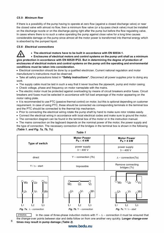
Fig. 7a. - connection Fig. 7b. Y – connection Fig. 7c. Y / - start
Type of switch
Motor PowerPN 4 kW
Motor PowerPN > 4 kW
power supply3 ~ 400 V
power supply3 ~ 400 V
direct Y – connection (7b) – connection(7a)
Y / - start ImpossibleRemove connecting
bridges (7c)
Table 1
ATTENTION
C5.5- Minimum flow
If there is a possibility of the pump having to operate at zero flow (against a closed discharge valve) or nearthe closed valve with almost no flow, then a minimum flow valve (or a by-pass check valve) must be installedon the discharge nozzle or on the discharge piping right after the pump but before the flow regulating valve.In cases where there is no such a valve operating the pump against close valve for a long time causesconsiderable damage on the pump since almost all the motor power is transformed into thermal energy whichis absorbed by the pumped liquid.
C5.6- Electrical connections
The electrical motors have to be built in accordance with EN 60034-1.Enclosures of electrical motors and control systems on the pump unit shall as a minimumgive protection in accordance with EN 60529 IP22. But in determining the degree of protection ofenclosures of electrical motors and control systems on the pump unit the operating and environmentalconditions must be taken into consideration.Electrical connection should be done by a qualified electrician. Current national regulation and motormanufacturer’s instructions must be observed.Take all safety precautions listed in “Safety instructions”. Disconnect all power supplies prior to doing anywork.The supply cable must be laid in such a way that it never touches the pipework, pump and motor casing.Check voltage, phase and frequency on motor nameplate with the mains. The electric motor must be protected against overloading by means of circuit breakers and/or fuses. Circuitbreakers and fuses must be selected in accordance with full load amperage of the motor appearing on themotor rating plate.It is recommended to use PTC (passive thermal control) on motor, but this is optional depending on customerrequirement. In case of using PTC, these should be connected via corresponding terminals in the terminal boxand the PTC should be connected to the thermal trip mechanism.Prior to connecting the electrical wiring rotate the pump shaft by hand to make sure rotor rotates easily.Connect the electrical wiring in accordance with local electrical codes and make sure to ground the motor.The connection diagram can be found in the terminal box of the motor or in the instruction manual.The mains connection on the tagboard depends on the nominal power of the motor, the power supply andthe type of connection. The necessary connection of the bridges in the terminal box is shown in the following(Table 1. and Fig. 7a, 7b, 7c).
In the case of three-phase induction motors with Y – – connection it must be ensured thatthe change-over points between star and delta follow on from one another very quickly. Longer change-overtimes may result in pump damage (Table 2).
www.bedu.eu

7
Motor Power Y - set time
30 kW > 30 kW
< 3 sec> 5 sec
Table 2
ATTENTION
ATTENTION
C5.7- Final check
After completion all the above process rotate the pump rotor several times by hand. Make sure rotor rotateseasily.Fix the safety guards back in places. Do not operate the pump before doing so. This is a necessity forsecurity and job safety.
D- START UP / SHUT DOWND1- Preparation
D1.1- Lubrication control
Since the bearings of motor are life-time lubricated type, they are maintenance free.
D1.2- Check the shaft seal (see F3)
D1.3- Venting and priming
Make sure that the pump and suction pipes are completely filled up with water. There is no problem for thepumps which have positive suction head. If there is a valve on suction line, it must be opened and air tapsare loosened to enable the water replaces air in the pump, until it is completely full with water.If there is a foot valve for the pump, which has suction lift, pump is filled up with water through the filling tapat the highest point of the pump and the air is emptied out.If the system has a vacuum pump, water is brought up in the rising pipe and filled up the pump through thisvacuum pump. When water is risen up to the highest point then the pump is started up.
Make sure the pump never runs dry.
D1.4- Checking the direction of rotation
BNM, BNM-V type pumps rotate in clockwise when it is looked from coupling to the pump. This direction isalready indicated on the pump nameplate by an arrow. Check this by switching the pump on, then off againimmediately. Fit the coupling guard back in place if you took it out.
D2- Start Up The Pump
Check if the shut off valve in the suction line is open and the shut off valve in discharge line is closed.Switch on the circuit breaker and run the motor.Wait until the motor reaches the full speed (on star-delta running motors wait until it switches on delta).Open the discharge valve slowly while watching the ampermeter on the control panel (if the discharge lineis empty do not turn on the valve fully open on first start up. Turn it on slowly to maintain the value on theampermeter is under the rated current value of the motor).When the valve is if fully open, check the pressure on the manometer and see it is the same with the dutypoint pressure. If the pressure on the pressure gauge is lower than duty point pressure brings them to the dutypoint value by slightly closing the valve. If it is higher value, check your installation, particularly head again.
The pump should be shut down at once and the trouble should be corrected if the pump isrunning at its rated speed and found any of the following faults:
Pump doesn’t deliver any water,Pump doesn’t deliver enough water,Flow is going down,Discharge pressure is not enough,Driver overloaded,Vibration on pump,High noise level,Bearing overheating
www.bedu.eu

8
D3- Shut Down The Pump
Slowly close the shut-off valve in the discharge line.You may shut down the pump without closing the shut-off valve if there is a device for water hammerprotection on the discharge line or the water hammer is not a considerable level.Switch off the driver. Ensure the pump set runs down smoothly and quietly to a standstill.Shut off external sealing liquid supply, if supplied, to relieve stuffing box pressure.If the set is to remain out of services for a long time close the shut-off valve in the suction pipe. Close offthe auxiliary connections. In the event of frost and/or prolonged standstill, drain the pump or otherwise protectagainst freezing.
D4- Checks to be Made While The Pump is Running
The pump must run smoothly, quietly and free from vibration at all times.The pump must never run dry.Never run the pump for along period against a closed discharge valve (At zero flow).The bearing temperature may exceed the ambient temperature by up to 50º C. But must never rise above80º C.The pump has a mechanical seal, these will experience only minor leakage or no visible leakage duringoperation. It is maintenance free. If there is considerable leakage from the seal, that means the seal surfacesare worn-out and it needs to be replaced. The operation life of the mechanical seal highly depends on thepurity of the water.Occasionally check the motor current. Stop motor if the amperage is higher than usual; there may be jammingor friction in the pump. Make the necessary mechanical and electrical checks.Stand-by pumps should be run for a short time at least once a week to ensure they are in constant readinessfor operation. Check the integrity of auxiliary connections.
E- LUBRICATION
The bearings of motor are always life-time grease lubricated and then maintenance-free.
The bearing temperature may exceed the ambient temperature by up to 50º C. But neverrise above 80º C.Do not reuse the bearings following disassembly for maintenance purposes.
F- DISASEMBLY, REPAIR AND REASSEMBLYBefore starting work on the pumpset, make sure it is disconnected from the mains and can not be switched on accidentally.
Follow the safety precaution measures outlined in “safety instructions”.
F1- Disassembly
Close all valves in the suctions and discharge lines, and drain the pump by opening the drain plug (230).Remove the safety guard. (See section N for safety guard).Detach pump suction and discharge flanges and all auxiliary supply lines if any, disconnect the pump setfrom the piping system.Dismantle the volute casing (001) from the seal cover (046) (Be careful to keep the seal cover (046) in placeto avoid any mechanical seal (405) trouble).Unscrew the end nuts (065) of the impeller and take out the impeller (050) and impeller key (210). Use rustremover solvent if necessary during dismantling.Take out the spacer sleeve (067).Pull out the rotating part of the mechanical seal (405).Dismantle the seal cover (046) and take out the stationary part of the mechanical seal (405) from the sealcover (046).Dismantle the motor pedestal (012).Unscrew the set-screws (380) of the pump shaft (060), or alliens of the rigid coupling (085) depending onconnection type.Pull off the pump shaft (060) from the motor (600) shaft.
ATTENTION
www.bedu.eu

9
F2- Reassembly
Reassembly proceeds in reverse sequence to disassembly as described in section F1. You may find theattached drawings useful (see sectional drawing in section M).Coat the seats and screw connections with graphite, silicon or similar slippery substance before reassembly.If you can not find any of the above you may use oil instead (except the pumps for drinking water).Never use the old o-rings and make sure the o-rings are the same size as the old ones.
F3- Shaft Seal
BNM type pumps are with mechanical shaft seals.
When operating properly the mechanical seal has no visible leakage. Usually mechanical seals do not requiremaintenance until leakage is visible but its tightness is to be checked regularly.Follow the instructions of mechanical seal manufacturers for the pumps having mechanical seals and NEVERRUN IT DRY!Mechanical seal diameters are given in Table 3.
A- For motor frame size up to 200 (See the section M1)
Make the alignment of the pump shaft’s location to providethe length as per the length “S” given in section L. (“S” isthe distance between the shaft shoulder and the end of themechanical seal chamber. See Fig. 8 ). Tighten the set-screws (for the shaft consists of 3 set-screws starting fromthe one in the middle and for the shaft consists of 2 set-screws start from the one near the motor).Place the stationary part of the mechanical seal into theseal chamber.Slip the rotating part of the mechanical seal onto thepump shaft (060) and place the spacer sleeve (067).
Place the impeller key (210) into keyway, slide the impeller (050) onto the shaft (060) and screw the impellernuts (065).Assemble the volute casing (001).Place the pump set on the baseplate. Connect suction and discharge pipes. Take the unit into operation asit was indicated in section D.
B- For motor frame size above 200 (See the section M2)
Place the motor (600) vertical as the shaft end comes to the upper side. Slip the rigid coupling (085) onto the motor shaft put the washer (370) onthe rigid coupling (085) and tighten by using imbus head bolt (340). So thatthe shaft end and the coupling end will be on the same plane (see Fig. 9). Tighten the set-screw (380) over the rigid coupling (085). Mount the pump shaft (060) to the rigid coupling (085). Assemble the motor pedestal (012) to the motor (600). Place the stuffing box cover (046) onto the motor pedestal (012). Place the stationary part of the mechanical seal into the seal chamber. Slip the rotating part of the mechanical seal onto the pump shaft (060) andplace the spacer sleeve (067). Place the impeller key (210) into keyway, slide the impeller (050) onto theshaft (060) and screw the impeller nuts (065). Assemble the volute casing (001). Place the pump set on the baseplate. Connect suction and discharge pipes.Take the unit into operation as it was indicated in section D.
Place the motor (600) vertical as the shaft end comes to the upper side.Assemble the motor pedestal (012) to the motor (600).Slip the pump shaft (060) onto the motor shaft.Place the stuffing box cover (046) onto the motor pedestal (012)
Casing Cover (046)
Pump Shaft (060) Motor Shaft (600)
Set-Screw (380)
Motor Shaft (600)
Rigid Coupling (085)
Set-Screw (380)
Washer (370)
Allen Bolt (340)
S
Fig. 8.
Fig. 9.
www.bedu.eu
10
PartNo
Part Name Number of Pumps in The System
060
050
020 - 021
420
405
067
Shaft (Incl. keys)
Impeller
Wear rings (if any)
O-Rings for Casing
Mechanical Seal
Spacer Sleeve
1
1
2
4
2
1
2
1
1
2
6
3
1
3
2
1
2
8
4
1
4
2
2
4
8
5
3
5
2
2
4
9
6
2
6-7
3
3
6
12
7
2
8-9
30%
10+
30%
50%
150%
Tablo 4
40%
20%
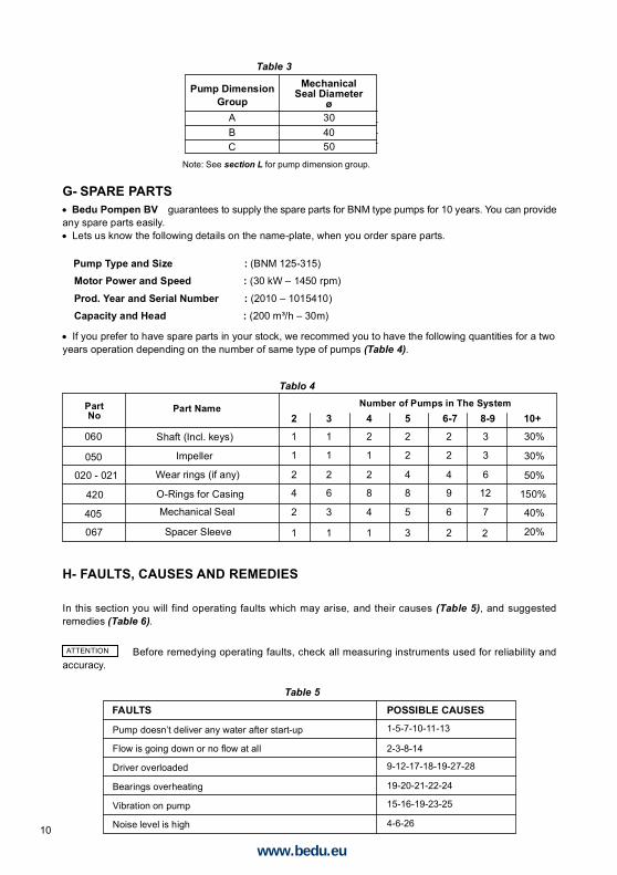
H- FAULTS, CAUSES AND REMEDIES
In this section you will find operating faults which may arise, and their causes (Table 5), and suggestedremedies (Table 6).
Before remedying operating faults, check all measuring instruments used for reliability andaccuracy.ATTENTION
Pump DimensionGroup
ABC
MechanicalSeal Diameter
ø304050
Table 3
Note: See section L for pump dimension group.
FAULTS POSSIBLE CAUSES
1-5-7-10-11-13
2-3-8-14
9-12-17-18-19-27-28
19-20-21-22-24
15-16-19-23-25
4-6-26
Table 5
Pump doesn’t deliver any water after start-up
Flow is going down or no flow at all
Driver overloaded
Bearings overheating
Vibration on pump
Noise level is high
G- SPARE PARTSBedu Pompen BV guarantees to supply the spare parts for BNM type pumps for 10 years. You can provideany spare parts easily.Lets us know the following details on the name-plate, when you order spare parts.
Pump Type and Size : (BNM 125-315)
Motor Power and Speed : (30 kW – 1450 rpm)
Prod. Year and Serial Number : (2010 – 1015410)
Capacity and Head : (200 m³/h – 30m)
If you prefer to have spare parts in your stock, we recommed you to have the following quantities for a twoyears operation depending on the number of same type of pumps (Table 4).
www.bedu.eu

11
POSSIBLE CAUSESThere may be air existing in pump orsuction pipe
Ingress of air through shaft seal,suction pipe or suction port. Pumplifts liquid with air
Air pocket in the suction pipe.
There is air in liquid
Too much suction lift
Pump is working at cavitationconditions
Insufficient manometric head.
Increase at total manometric head.
Pump is operating at lowermanometric head.
Reverse rotation.
Speed is too low.
Speed is too high.
Impeller or check valve or strainer isclogged.Impeller or strainer is clogged partially.
Partially clogged impeller.
Worn out and defected impeller.
Mechanical frictions inside the pump.
Excess tightened soft packing.
Bad coupling alignment.
Bearing covers are too tight.The pumped flow is less than theminimum flow required.Existence of excess grease.
Oblique shaft.
Insufficient lubrication or lubricatingoil/grease dirty, contaminated.Unbalanced rotating parts.
Pump runs out of duty range.
The density or viscosity of the liquidpumped is higher than that originallyspecified.
Defects in motor.
Check the slope of the suction line make sure that there is no reasonfor formation of air pockets
Suction pipe is not submerged enough creating vortex. Check liquidlevel in suction tank or increase the depth of suction pipe or foot valvein the liquid.
If no obstruction at inlet check the friction losses of suction line, largerpiping may correct condition. If static lift is too high, the liquid level inthe suction tank must be raised or the pump lowered.
NPSH available is too low. Check liquid level in suction tank, checksuction line for excessive friction losses. Check isolating valve insuction line to make sure it is completely open. If necessary increasesuction head on pump by lowering the pump.
The actual total head is higher than that originally specified. Check thegeodetic total head and friction losses in the discharge line. Largerpiping may correct the condition. Check that valves are fully open.
Check that valves are fully open. Check that there is any obstruction indischarge pipe.The actual total head is lower than that originally specified. Machineimpeller outer diameter to size advised by supplier.Check motor rotation with directional arrow on pump casing ornameplate.
Check the supply voltage and frequency or motor may have open phase.
If possible decrease the pump rotational speed or turn down the impellerouter diameter to size advised by supplier.
Clean the impeller or check valve or strainer
Clean the impeller or strainer.
Clean the impeller.
Replace impeller.
Check pump rotor for any rotor obstruction or deflection.
Loosen the nuts of the packing gland.
Check the coupling rubber and realign the coupling.
Check and make necessary modification on the cover.
Increase the flow. If necessary use by-pass recirculating valve or line.
Remove excess grease.
Check the shaft and replace it if necessary.Check the amount of oil/grease. Clean the bearings and bearinghousing and relubricateCheck the balance of the rotating parts.
Check the values of operating point.
Use a more powerful motor.
Check any motor defects. The motor may not be ventilated properlydue to a poor location.
1
2
3
4
5
6
7
8
9
10
11
12
13
14
15
16
17
18
19
20
21
22
23
24
25
26
27
28
REMEDIES
Table 6
Check for leaks in suction pipe joints and fittings. Check shaft seal ifnecessary increase the pressure of sealing liquid. Check the dept ofsuction pipe or foot valve in the liquid and if necessary increase thedepth of them.
Fill pump and suction pipe completely with liquid and repeat the primingprocedure.
www.bedu.eu

12
I- TIGHTENING TORQUES
J- EXPECTED NOISE VALUES
Tightening TorquesTightening Torque max (N.m)
Property ClassesThread Diameter8.8 10.93.05.9102549851352103004255807301100145019702530
4.48.715367212520031043061082010501550210027703560
M4M5M6M8M10M12M14M16M18M20M22M24M27M30M33M36
Power of MotorP
(kW)
Sound pressure level (dBA) *(Pump with motor)
1450 rpm 2900 rpm
< 0.550.751.11.52.234
5.57.51115
18.52230374555
6060626364656667697072737475757677
6466666869707173747677787981828284
N
(*) Without protective sound hood, measured at a distance of 1 m directly above the driven pump, in a free space above asound reflecting surface.
www.bedu.eu

13
x y
z
x y
z
K- PERMISSIBLE FORCES AND MOMENTS AT THE PUMP FLANGES
Pump TypeBNM 100-250
Inlet Flange (DN)125 100
Outlet Flange (DN)
* Forces in Newton [N], moments in Newton x Meter [N.m].** Values are applicable for casing material “Grey Cast Iron (EN-JL-250 / GG25)”.Higher values are permissible for steel construction pumps.
Attention: The real forces and moments which affects on flanges must be satisfied following equations;
InletFx (N)
Outlet
200Fy (N)400
Fz (N)-500
Fx (N)250
Fy (N)0
Fz (N)400
InletMx (Nm)
90My (Nm)
100Mz (Nm)
-170Mx (Nm)
100My (Nm)
0Mz (Nm)
85
Outlet
32-16032-20040-20040-25050-16050-20050-25050-31565-16065-20065-25065-31580-20080-25080-31580-400100-200100-250100-315100-400
Type125-200125-250125-315125-400150-200150-250150-315150-400
Type
F
Fv
v max.
F
Fh
h max.
M
Mt
t max.
| Fz inlet | + | Fz outlet | Fv
[ (Fx inlet)2 + (Fy inlet)2 ]1/2 + [ (Fx outlet)2 + (Fy outlet)2 ]1/2 Fh
[ (Mx inlet)2 + (My inlet)2 + (Mz inlet)2 ]1/2 + [ (Mx outlet)2 + (My outlet)2 + (Mz outlet)2 ]1/2 Mt
Fv
1300
1400
1500
1800
2300
3100
Fh
950
1000
1100
1300
1500
1900
F
1600
1700
1800
2200
2700
3600
M
180
200
280
450
630
930
Fv
4200
5000
Fh
2600
3300
F
4900
6000
M
1400
1800
tt
| -500 | + | 400 | = 900 2200 N
[ 2002 + 4002 ]1/2 + [ 2502 + 02 ]1/2 = 697 1300 N
[ 902 + 1002 + (-170)2 ]1/2 + [ 1002 + 02 + 852 ]1/2 = 348 650 Nm
[ 900 / 2200 ]2 + [ 697 / 1300 ]2 + [ 348 / 650 ]2 = 0.74 1
Example: Calculations of forces and moments on flanges
Let the forces and moments be given as follows;
www.bedu.eu

14
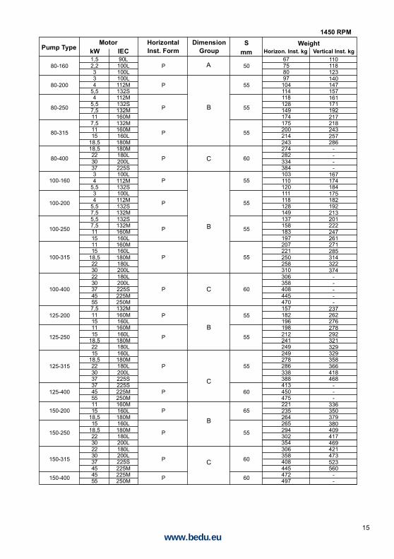
1450 RPML- PUMP DIMENSION GROUPS AND WEIGHTS
32-125
32-160
32-200
32-250
40-125
40-160
40-200
40-250
40-315
50-125
50-160
50-200
50-250
50-315
65-125
65-160
65-200
65-250
65-315
65-400
39404446475354566668767944454748495157596169727482859194
10111146484952545662647275858895
10511912915017555565858606870788188
100107117138117138163177208222251259311
0,250,370,370,550,750,550,751,11,11,52,23
0,250,370,550,550,751,1
0,751,11,52,21,11,52,23
2,234
5,50,370,550,750,751,11,51,11,52,23
2,234
5,54
5,57,511
0,550,751,11,11,52,21,52,23434
5,57,55,57,511151115
18,52230
71M71M71M80M80M80M80M90S90S90L
100L100L71M71M80M80M80M90S80M90S90L
100L90S90L
100L100L100L100L112M132S71M80M80M80M90S90L90S90L
100L100L100L100L112M132S112M132S132M160M80M80M90S90S90L
100L90L
100L100L112M100L112M132S132M132S132M160M160L160M160L180M180L200L
DimensionGroupkW IEC Horizon. Inst. kg
Smm
MotorPump Type
A
B
HorizontalInst. Form
WeightVertical Inst. kg
67687274758182849496
104107757678798082889092
1001031051131161221251321427779808385879395
1031061161191261361571671882139394969698
106108116119126138145155176155176201215
-----
P
P
P
P
P
P
P
P
P
P
P
P
P
P
P
P
P
P
P
P
A
B
50
50
50
50
50
50
50
50
50
50
50
50
50
55
50
50
50
55
55
55
www.bedu.eu
15
80-160
80-200
80-250
80-315
80-400
100-160
100-200
100-250
100-315
100-400
125-200
125-250
125-315
125-400
150-200
150-250
150-315
150-400
67758097
104114118128149174175200214243274282334384103110120111118128149137158183197207221250258310306358408445470157182196198212241249249278286338388413450475221235264265294302354306358408445472497
1,52,2334
5,54
5,57,5117,51115
18,518,522303734
5,534
5,57,55,57,511151115
18,5223022303745557,511151115
18,52215
18,52230373745551115
18,515
18,52230223037454555
90L100L100L100L112M132S112M132S132M160M132M160M160L180M180M180L200L225S100L112M132S100L112M132S132M132S132M160M160L160M160L180M180L200L180L200L225S225M250M132M160M160L160M160L180M180L160L180M180L200L225S225S225M250M160M160L180M160L180M180L200L180L200L225S225M225M250M
Smm
Motor
A
C
110118123140147157161171192217218243257286
----
167174184175182192213201222247261271285314322374
-----
237262276278292321329329358366418468
---
336350379380409417469421473523560
--
C
B
P
P
P
P
P
P
P
P
P
P
P
P
P
P
P
P
P
P
B
C
B
B
C
50
55
55
55
60
55
55
55
55
60
55
55
55
60
65
55
60
60
1450 RPMDimension
GroupkW IEC Horizon. Inst. kgPump TypeHorizontalInst. Form
WeightVertical Inst. kg
www.bedu.eu

16
2900 RPM
32-125
32-160
32-200
32-250
40-125
40-160
40-200
40-250
50-125
50-160
50-200
50-250
65-125
65-160
65-200
65-250
80-160
80-200
43464855596769747681
12591
13514253606870697176
12084
128135141148163186223616971767479
123131138153176166189226245767883
103127134149159182219201238257299333134141156179198235254296
1,11,52,2334
5,57,55,57,5117,511152,234
5,54
5,57,5117,511151115
18,5223034
5,57,55,57,5111115
18,522
18,52230374
5,57,5111115
18,518,5223022303745551115
18,52222303745
80M90S90L
100L100L112M132S132S132S132S160M132S160M160M90L
100L112M132S112M132S132S160M132S160M160M160M160M160L180M200L100L112M132S132S132S132S160M160M160M160L180M160L180M200L200L112M132S132S
C132M160M160M160L160L180M200L180M200L200L225M250M160M160M160L180M180M200L200L225M
Smm
B
A
P
P
P
MP
M
P
M
P
MPM
P
M
P
M
P
M
M
P
M
P
M
P
MP
M
P
M
M
50
50
50
50
50
50
50
50
50
50
50
50
50
50
50
50
50
55
71747683879597
102104109153119163170849199
10110010210715111515916617217919421725492
100102107105110154162169184207197220257276114116121165165172187197220257239276295337371177184199222
----
DimensionGroupkW IEC Horizon. Inst. kg
MotorPump Type HorizontalInst. Form
WeightVertical Inst. kg
www.bedu.eu

17
M1- SECTIONAL DRAWINGS (VERTICAL INSTALLATION)
80-250
100-160
100-200
100-250
268310344241260302249268310344319353
374555303745303745554555
200L225M250M200L200L225M200L200L225M250M225M250M
Smm
B
M
M
M
M
55
55
55
55
2900 RPM
---
--------
DimensionGroupkW IEC Horizon. Inst. kg
MotorPump Type HorizontalInst. Form
WeightVertical Inst. kg
001
046
060
012
011
050
065067
210
405
420
600
380
230
360
300
320
321
361
www.bedu.eu

18
M2- SECTIONAL DRAWINGS (FOR MOTOR FRAME SIZE UP TO 200)
405067 420 012*021
001
065
600060046 380
210
050
*020
230
360 300 320
* Optional
PARTS LIST
Volute CasingSuction ElbowMotor PedestalWear Ring (Casing)Wear Ring (Casing Cover)Casing CoverImpellerPump ShaftImpeller NutSepecer SleveRigid CouplingImpeller KeyDraing Plug
001011012*020*021046050060065067085210230
300320321340341360361370380405420600
StudHex. Head BoltHex. Head BoltAllen BoltAllen BoltHex. NutHex. NutWasherSet-ScrewMechanical SealO-RingElectric Motor
www.bedu.eu

19
M3- SECTIONAL DRAWINGS (FOR MOTOR FRAME ABOVE 200)
www.bedu.eu
20
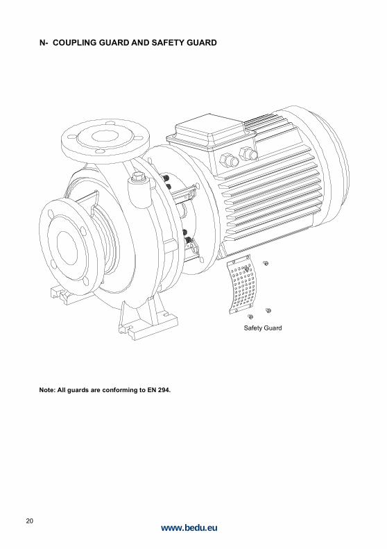
N- COUPLING GUARD AND SAFETY GUARD
Safety Guard
Note: All guards are conforming to EN 294.
www.bedu.eu

EC – Declaration of Conformity
Manufacturer Details
TradenameBedu Pompen BV
Address
Poort van Midden Gelderland Rood 10, 6666 LT, Heteren, Netherlands
Product DetailsProduct Name
Centrifugal pumps
Model (+series) NameBNM / BNMV
Applicable Standards DetailsDirectives
2006/42/EC (Machinery Directive)2014/35/EU (Low Voltage Directive)2014/30/EU (Electromagnetic compatibility)
Standards
EN-ISO 12100:2010EN-IEC 60204-1:2006EN 809+A1/C1
Additional information
No further details.
Declaration
We hereby declare under our sole responsibilitythat the product(s) mentioned above to which thisdeclaration relates complies with the abovementioned standards and Directives.
BEDU Pompen BVPoort van Midden Gelderland Rood 106666 LT HeterenTel : +31 (0)88 – 4802 900Fax : +31 (0)88 – 4802 901E-mail : [email protected] : www.bedu.eu
Name Director(s): Issued Date:
01/10/ 2014
Marco Breunissen Ron Bijen
Signature of representative(s)
www.bedu.eu

www.bedu.eu

Deskundig advies
Een klantgerichte organisatie die zich aanpast aan de eisen en wensen van uw organisatie
Innovatieve en maatwerkoplossingen
Breed assortiment vloeistofpompen van gerenommeerde merken
Meer dan 5.000 pompen en 20.000 onderdelen op voorraad
Een snelle en passende oplossing voor al uw vraagstukken
Wij zien het belang in van uw processen en de continuïteit van uw bedrijfsvoering
Snelle reactie- en levertijden
Een eigen Technische Dienst met uitgebreide testfaciliteiten, werkend vanuit onze eigen werkplaats of bij u op locatie
Reparatie, onderhoud en revisie van alle soorten en merken vloeistofpompen
Storingsdienst 24 uur per dag, 7 dagen in de week
made for your process
BEDU POMPEN B.V.
Poort van Midden Gelderland Rood 10
6666 LT HETEREN
Nederland
Telefoon +31 (0)88 4802 900
Fax +31 (0)88 4802 901
E-mail [email protected]
WWW.BEDU.nl
BEDU BELGIUM B.V.B.A.
Heuvelstraat 52
B-1981 HOFSTADE
België
Telefoon +32 (0)15 33 16 77
Fax +32 (0)15 33 16 73
E-mail [email protected]
WWW.BEDU.BE