Embed Size (px)
DESCRIPTION
BMTDSL-Landing-Craft-Conpaper-MAST-Nov08
Citation preview

November 2008 Page 1 of 11 © BMT Defence Services Ltd
Paper presented at MAST 2008, Cadiz, Spain
Landing Craft - Simple Ships or Time for a Rethink?
A Designer’s Perspective
Ian Mackereth BSc CEng MRINA, Managing Naval Architect Nick Noel-Johnson BEng MSc CEng MRINA, Principal Naval Architect
BMT Defence Services Ltd, UK
SYNOPSIS
Are landing craft simple ships or should they be regarded as some of the most challenging designs in the marine environment, in terms of the balance between
functionality, performance and safety?
This paper will propose that in order to make landing craft truly effective it is
necessary to understand in more detail some of the unique challenges posed by their role. It is contended that these challenges are not fully understood, leading
to unbalanced requirements and exposure of the operators to unnecessary risks. This paper discusses links between landing craft capabilities and the concept of
operations and reviews the primary challenges and safety concerns in the design of the craft. Catalysts are proposed to encourage step improvements in landing
craft technology, thus overcoming some of the traditional problems inherent in
their design and meeting the capability requirement in a more cost effective way.
INTRODUCTION
Landing craft are an essential part of the system required to deliver amphibious forces, vehicles,
equipment and supplies to a beachhead. In various forms, they have been a feature of naval amphibious warfare for centuries, however for the past 60 to 70 years the design of landing craft
has remained relatively unchanged.
Whilst landing craft look simple, this paper contends that appearances can be deceptive and seeks
to present an argument for why landing craft are not simple ships at all. It is proposed that landing
craft should be regarded as some of the most challenging designs in the marine environment in
terms of the balance between functional performance and the safe provision of enduring capability.
Figure 1 - Army LCM 8 being lowered from HMAS Kanimbla © Commonwealth of Australia credit Department of Defense

November 2008 Page 2 of 11 © BMT Defence Services Ltd
This paper highlights and explains some of the unique challenges that are faced by the designer
due to the role of landing craft, why in some cases this challenge is not always recognised and subsequently to present the reasoning behind why a rethink of the approach to certain areas of
landing craft design is required.
CONTEXT
Use of the term landing craft can be applied to a wide range of vessels, which vary in size from a
few tonnes to thousands of tonnes. For the purposes of the following discussion the term landing craft is used in relation to vessels whose size lies in the range of 20 tonnes to 850 tonnes full load
displacement (~15m (LCVP) to ~65m (LCT) length).
Figure 2 - RN LCVP Mk5b’s, LCU Mk10’s and LPD
© Crown Copyright/MOD, image from www.photos.mod.uk
THE CHALLENGES
Scenario
As a vehicle for highlighting a selection of these design challenges a much simplified operational scenario is considered below. Against each of the phases of the operation, examples of associated
design challenges are discussed.
The examples can be split into two groups:
• Areas that pose new challenges within existing standard naval architectural
considerations for ship design (e.g. designing for stability is a standard area of
naval architecture for all ship types, however, the response to the environment may be different for an LC, and therefore this is a new challenge, existing codes
may not be applicable);
• Areas that are new or unusual considerations in the design of ships (e.g. designing
for grounding, ramp to ramp transfer etc) and are, in general, circumstances
unique to landing craft.
November 2008 Page 3 of 11 © BMT Defence Services Ltd
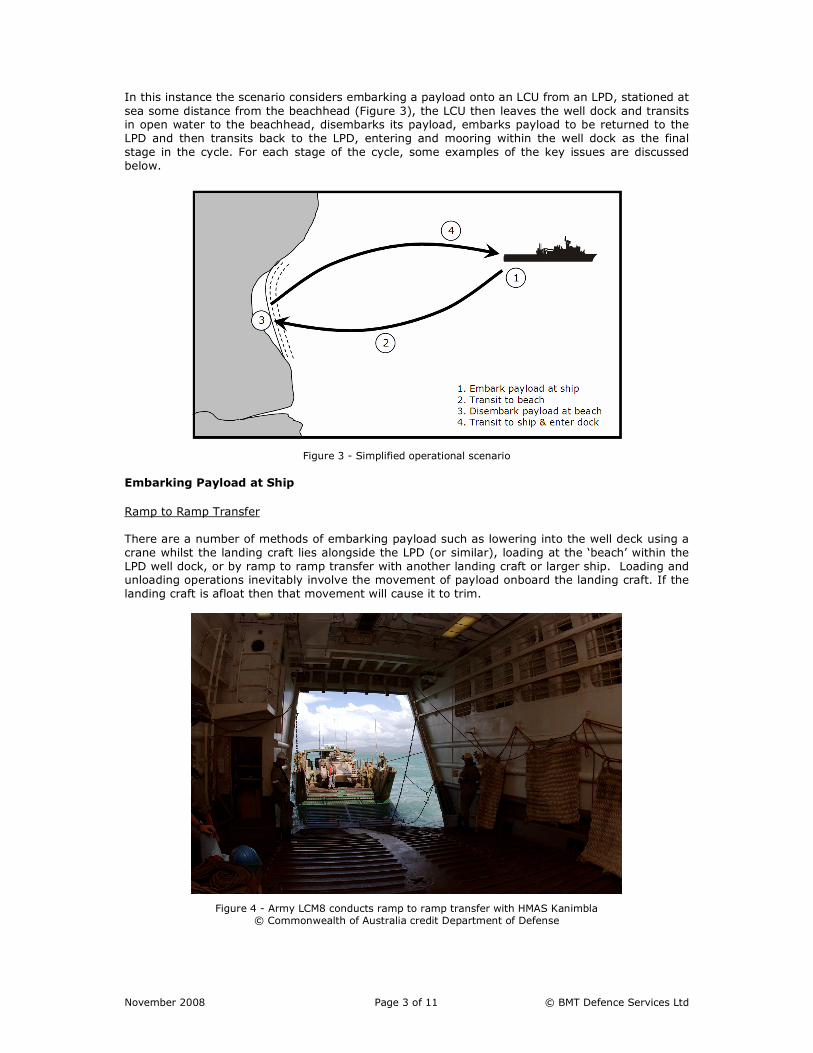
In this instance the scenario considers embarking a payload onto an LCU from an LPD, stationed at
sea some distance from the beachhead (Figure 3), the LCU then leaves the well dock and transits in open water to the beachhead, disembarks its payload, embarks payload to be returned to the
LPD and then transits back to the LPD, entering and mooring within the well dock as the final
stage in the cycle. For each stage of the cycle, some examples of the key issues are discussed
below.
Figure 3 - Simplified operational scenario
Embarking Payload at Ship
Ramp to Ramp Transfer
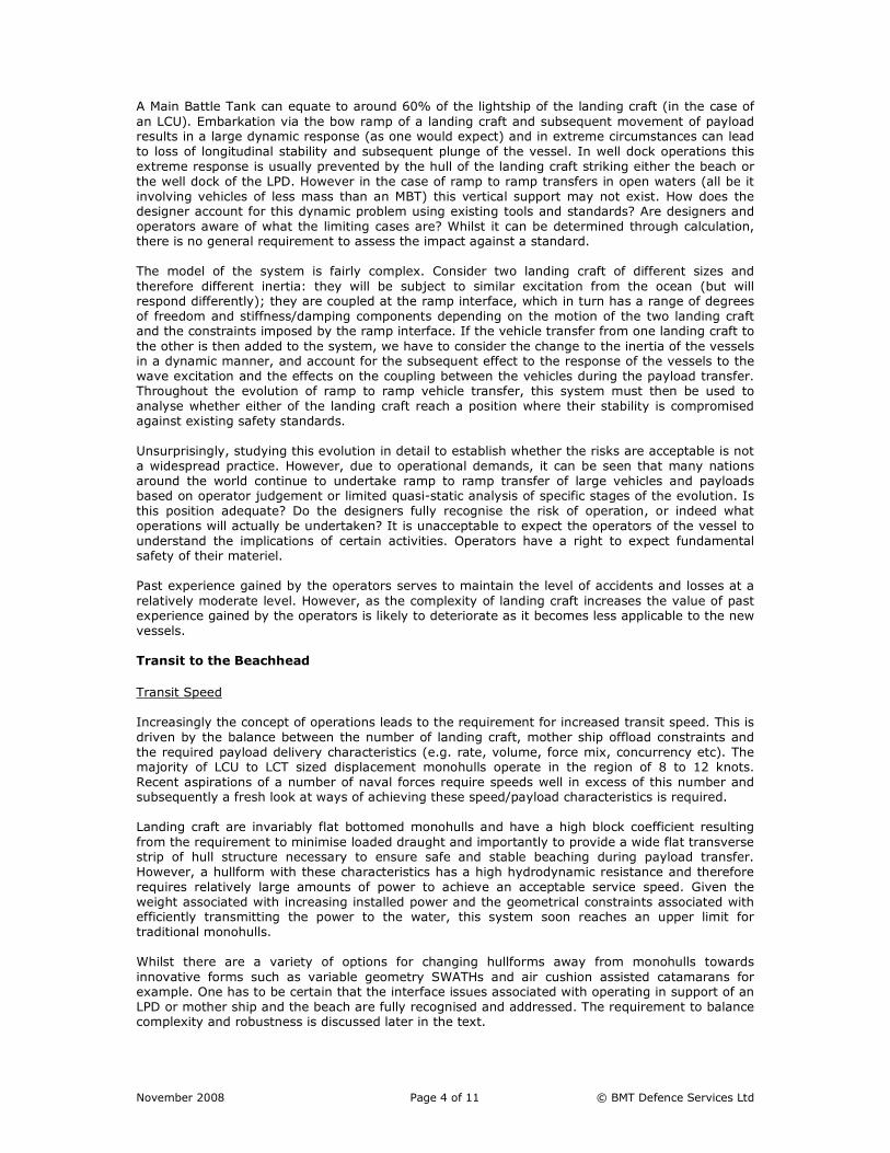
There are a number of methods of embarking payload such as lowering into the well deck using a
crane whilst the landing craft lies alongside the LPD (or similar), loading at the ‘beach’ within the
LPD well dock, or by ramp to ramp transfer with another landing craft or larger ship. Loading and unloading operations inevitably involve the movement of payload onboard the landing craft. If the
landing craft is afloat then that movement will cause it to trim.
Figure 4 - Army LCM8 conducts ramp to ramp transfer with HMAS Kanimbla
© Commonwealth of Australia credit Department of Defense
November 2008 Page 4 of 11 © BMT Defence Services Ltd
A Main Battle Tank can equate to around 60% of the lightship of the landing craft (in the case of
an LCU). Embarkation via the bow ramp of a landing craft and subsequent movement of payload results in a large dynamic response (as one would expect) and in extreme circumstances can lead
to loss of longitudinal stability and subsequent plunge of the vessel. In well dock operations this
extreme response is usually prevented by the hull of the landing craft striking either the beach or
the well dock of the LPD. However in the case of ramp to ramp transfers in open waters (all be it
involving vehicles of less mass than an MBT) this vertical support may not exist. How does the designer account for this dynamic problem using existing tools and standards? Are designers and
operators aware of what the limiting cases are? Whilst it can be determined through calculation, there is no general requirement to assess the impact against a standard.
The model of the system is fairly complex. Consider two landing craft of different sizes and
therefore different inertia: they will be subject to similar excitation from the ocean (but will respond differently); they are coupled at the ramp interface, which in turn has a range of degrees
of freedom and stiffness/damping components depending on the motion of the two landing craft and the constraints imposed by the ramp interface. If the vehicle transfer from one landing craft to
the other is then added to the system, we have to consider the change to the inertia of the vessels in a dynamic manner, and account for the subsequent effect to the response of the vessels to the
wave excitation and the effects on the coupling between the vehicles during the payload transfer. Throughout the evolution of ramp to ramp vehicle transfer, this system must then be used to
analyse whether either of the landing craft reach a position where their stability is compromised
against existing safety standards.
Unsurprisingly, studying this evolution in detail to establish whether the risks are acceptable is not
a widespread practice. However, due to operational demands, it can be seen that many nations
around the world continue to undertake ramp to ramp transfer of large vehicles and payloads based on operator judgement or limited quasi-static analysis of specific stages of the evolution. Is
this position adequate? Do the designers fully recognise the risk of operation, or indeed what
operations will actually be undertaken? It is unacceptable to expect the operators of the vessel to
understand the implications of certain activities. Operators have a right to expect fundamental safety of their materiel.
Past experience gained by the operators serves to maintain the level of accidents and losses at a
relatively moderate level. However, as the complexity of landing craft increases the value of past experience gained by the operators is likely to deteriorate as it becomes less applicable to the new
vessels.
Transit to the Beachhead
Transit Speed
Increasingly the concept of operations leads to the requirement for increased transit speed. This is
driven by the balance between the number of landing craft, mother ship offload constraints and
the required payload delivery characteristics (e.g. rate, volume, force mix, concurrency etc). The majority of LCU to LCT sized displacement monohulls operate in the region of 8 to 12 knots.
Recent aspirations of a number of naval forces require speeds well in excess of this number and subsequently a fresh look at ways of achieving these speed/payload characteristics is required.
Landing craft are invariably flat bottomed monohulls and have a high block coefficient resulting
from the requirement to minimise loaded draught and importantly to provide a wide flat transverse strip of hull structure necessary to ensure safe and stable beaching during payload transfer.
However, a hullform with these characteristics has a high hydrodynamic resistance and therefore
requires relatively large amounts of power to achieve an acceptable service speed. Given the
weight associated with increasing installed power and the geometrical constraints associated with efficiently transmitting the power to the water, this system soon reaches an upper limit for
traditional monohulls.
Whilst there are a variety of options for changing hullforms away from monohulls towards
innovative forms such as variable geometry SWATHs and air cushion assisted catamarans for example. One has to be certain that the interface issues associated with operating in support of an
LPD or mother ship and the beach are fully recognised and addressed. The requirement to balance complexity and robustness is discussed later in the text.

November 2008 Page 5 of 11 © BMT Defence Services Ltd
Stability (Open Water & Surf Zone)
As discussed in the initial stages of this paper, landing craft in this instance are relatively small box
shaped craft. When considering the stability of these craft it is proposed that an alternative
approach is required to that conventionally adopted. It is convenient to consider landing craft as computationally simple but it is a mistake to consider them conceptually simple.
The ‘traditional’ metacentre approach to stability relates to static heeling of a ship due to the
movement of load in calm water. Its use has been extended, by Sarchin and Goldberg et al, to considering rolling in waves small relative to the ship. That is, it assumes that the surface of the
water is essentially flat over the beam of the vessel. Using this assumption, the stability of the vessel can be based on the transfer of buoyancy as represented by wedges.
In the case of a small vessel it is possible for the waves to be large relative to the beam of the
vessel and for the vessel to be momentarily in an environment consisting of ‘sloping water’. In this case, the transfer of buoyancy serves to upset the vessel and not restore it. It is proposed that it
is therefore reasonable to revisit the original assumption.
This serves to suggest that there is something here that the designer does not fully understand.
Perhaps it is necessary to consider the situation dynamically rather than statically.
A further complicating factor is that of the common feature across the range of landing craft
considered in this paper: the open well deck. Whilst normally fitted with freeing ports to facilitate
the removal of water from the deck, the usually unavoidable frequency of green seas invariably
leads to a transient addition of mass and free surface of water on the well deck. This serves to
degrade the stability performance of the landing craft further. The design of freeing ports for landing craft remains far from ideal and the need to assure as satisfactory balance between
watertight integrity and the removal of fluid free surfaces from the well deck remains unresolved.
Seakeeping
A typical landing craft can be expected to carry something of the order of its lightship in payload.
Even though tankers and bulk carriers exceed this ratio it is suggested that their size is great relative to the environmental forces (waves and wind). Thus the effect of the latter is very much
greater for the landing craft. The payload for a landing craft can be literally anything; from a point load to an even distribution. Locomotives and even sheep are known to have been carried.
Furthermore the payload is expected to move, at least to unload. The latter has stability
connotations when the landing craft is afloat. The moment of inertia can vary significantly and thus the craft response to the environment also be expected to vary significantly. It is proposed that
this is included in the design process as a factor to consider, particularly when one considers the suggestion that stability should be considered dynamically rather than through quasi-static
methods. Should it also then be included in the assurance process?
The requirement to adequately secure the payload to prevent unplanned movement is also of
great importance given the potentially catastrophic effect on stability. The range of payload geometry and mass is large; finding a common solution is difficult. Do the designers understand
the dynamic forces that the securing devices will be subject to (given the widely varying dynamic response of the landing craft to the seaway depending on payload type and distribution)? Further
to the technical challenges that face the designer, he or she must also be content that they have sufficiently communicated the operational limits or envelope of safe operation to the operators.
Are current provisions adequate?
Disembark/Embark Payload at the Beachhead
Grounding (or Beaching)
One of the most unique aspects of landing craft is the requirement to ground the vessel repeatedly
on unprepared and frequently uneven and rough beach surfaces. This sort of event for the majority of other conventional vessels would result in severe damage and a subsequent period in
dock to facilitate repairs.
November 2008 Page 6 of 11 © BMT Defence Services Ltd
When a landing craft is beached, the support to the structure and payload is imperfect; being via
the beach which may have an irregular surface. An added complication to this is that the payload can also travel over the ship length when unloading. It is likely that this grounded condition
(where in extreme cases the landing craft may even be dried out) is the design driver if
precautions against permanent set to hull structure are to be considered. At the same time the
consequences of accelerated wastage, and abrasion, of the bottom must also be remembered.
The designer faces new challenges here surrounding his understanding of the load cases that the
hull structure will be subject to, selection of appropriate design margins and ensuring sound structural continuity despite the space constraints and multiple attempts from other areas of the
design to prevent this occurring.
The evolution of disembarking and embarking payload at the beachhead is founded on the premise
that the landing craft can subsequently retract from the beach (or un-ground itself). Whilst
operator skill in terms of positioning the landing craft, controlling trim and selected use of kedging lines have a great deal to offer to the success of withdrawal from the beach, the designer has a
responsibility to ensure that the design of the hull form does not unduly hamper the evolution. Hull geometry features that for example promote reduced hydrodynamic resistance, improve trim at
speed (for example as fitted to some LCVPs) and indeed the means of propulsion, can prevent astern movement on the beach. This further constrains the choice of propulsor and some aspects
of hull form design; again something relatively unique to the field of landing craft.
Transit to the Ship
General
Not discounting the difficulties accompanying leaving the beach and executing a 180 degree turn between sets of waves (to avoid the risk of capsize in the surf zone) and the other open water
transit related aspects discussed earlier, the most challenging evolution in returning to the ship is the entry to the well dock of the ship (in the case of an LPD).
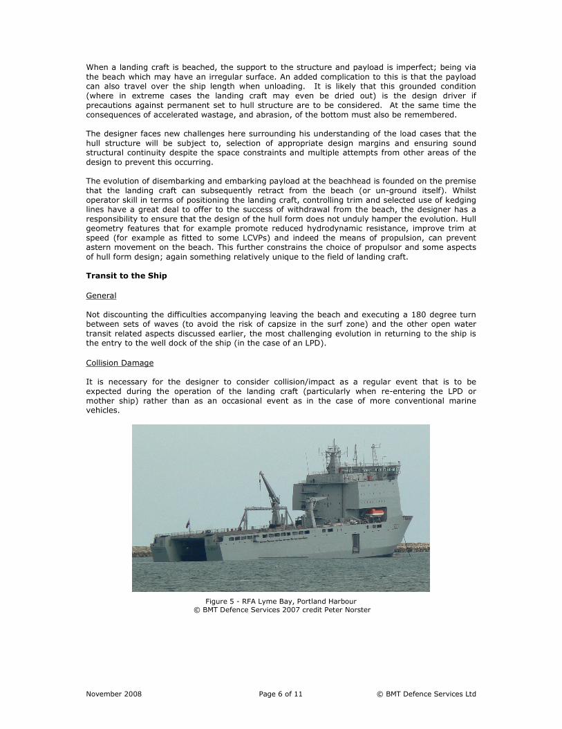
Collision Damage
It is necessary for the designer to consider collision/impact as a regular event that is to be
expected during the operation of the landing craft (particularly when re-entering the LPD or
mother ship) rather than as an occasional event as in the case of more conventional marine vehicles.
Figure 5 - RFA Lyme Bay, Portland Harbour © BMT Defence Services 2007 credit Peter Norster
November 2008 Page 7 of 11 © BMT Defence Services Ltd
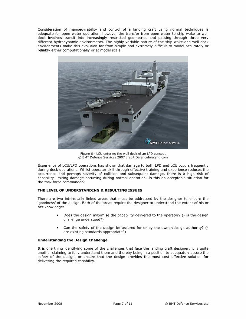
Consideration of manoeuvrability and control of a landing craft using normal techniques is
adequate for open water operation, however the transfer from open water to ship wake to well dock involves transit into increasingly restricted geometries and passing through three very
different hydrodynamic environments. The highly variable nature of the ship wake and well dock
environments make this evolution far from simple and extremely difficult to model accurately or
reliably either computationally or at model scale.
Figure 6 - LCU entering the well dock of an LPD concept © BMT Defence Services 2007 credit DefenceImaging.com
Experience of LCU/LPD operations has shown that damage to both LPD and LCU occurs frequently
during dock operations. Whilst operator skill through effective training and experience reduces the
occurrence and perhaps severity of collision and subsequent damage, there is a high risk of capability limiting damage occurring during normal operation. Is this an acceptable situation for
the task force commander?
THE LEVEL OF UNDERSTANDING & RESULTING ISSUES
There are two intrinsically linked areas that must be addressed by the designer to ensure the
‘goodness’ of the design. Both of the areas require the designer to understand the extent of his or her knowledge:
• Does the design maximise the capability delivered to the operator? (- is the design
challenge understood?)
• Can the safety of the design be assured for or by the owner/design authority? (-
are existing standards appropriate?)
Understanding the Design Challenge
It is one thing identifying some of the challenges that face the landing craft designer; it is quite
another claiming to fully understand them and thereby being in a position to adequately assure the safety of the design, or ensure that the design provides the most cost effective solution for
delivering the required capability.

November 2008 Page 8 of 11 © BMT Defence Services Ltd
Whilst naval architects and naval engineers design to their best ability a craft to safely and
effectively provide the user with a certain capability, design authorities must rely on extant standards for conventional ships as tools with which to assure themselves that the vessel is in fact
safe to operate in the intended environment. It is contended that this situation is again because
the challenges that face the designer relating to safely achieving the required capability are not
fully recognised and understood.
Are Existing Standards Appropriate?
Despite their critical importance to conducting an amphibious assault, landing craft appear to be
the forgotten cousins of the conventional naval flotilla. Until recently little attention had been paid to development of any specific landing craft design guidance and standards; leaving landing craft
subject to design standards and guidance derived originally with frigates and destroyers in mind.
For example, as alluded to earlier in the text, extant naval stability standards are not necessarily appropriate and therefore strict compliance with ship criteria may yield little benefit to the safety
of the operator. The current quasi static stability standards applied to warships are based on historical experience gained from conventional ship designs of the 1940’s and 1950’s. The
pedigree of these standards could be said to be borne out by many years of safe service, however, there are valid reasons to further develop these stability criteria to suit the landing craft problem,
for example:
• The standards do not directly address dynamic behaviour in extreme conditions;
• Their validity is questionable given the very different hull form of landing craft
compared to those against which the standards were originally developed;
• The level of safety assured by compliance with the criteria and the risk to a vessel
of non-compliance needs to be understood.
Resulting Issues
Translating a high level capability requirement into a set of (solution orientated) technical
requirements without full cognisance and understanding of the challenges that face the designer
can lead to overly complex and expensive equipment being provided to the end user. It is
contended that requirements should not be set in isolation to the designer who holds the appropriate knowledge. Early engagement of industry is crucial to successful provision of enduring
capability.
Alternative solutions to meet user requirements that can be developed in conjunction with the
operator will offer affordable capability due to the ability to balance achievability and aspirations.
From a safety perspective, failure to address the challenges outlined above will mean that the
operators remain exposed to unnecessary risk. The prospect of capsize from for example
broaching in surf or heavy seas, or uncontrollable flooding due to structural damage are very real. Additionally, even minor damage to critical areas of the hull from docking operations (such as a
ballast tank) can result in the capability of the landing craft, and therefore the amphibious capability of the task force, being severely restricted.
It is also important that the extent of the designer’s knowledge is passed on to the operator in the
form of operator guidance. A sad example of where this failed to occur is the case of a Canadian civilian cargo landing craft capsized because of a loss of initial transverse stability due to the free-
surface effect of water accumulating on deck. The water accumulation was caused primarily by the
deteriorated condition of the bow ramp seal. The board of inquiry found that “…The fact that the
vessel's operators and managers were not sufficiently knowledgeable to recognize that the ineffective ramp/hull seal seriously compromised the vessel's stability…”.
Areas for Development
Some areas that require attention in the immediate future are as follows:
• Understanding dynamic stability of the landing craft in both open water and the surf
zone;
November 2008 Page 9 of 11 © BMT Defence Services Ltd
• Designing for repair;
• Designing to withstand damage;
• Balancing complexity and robustness.
Taking the final point, it is proposed that the need for landing craft to be robust is indisputable. Robustness can be interpreted to mean that the craft should be simple, reliable, tolerant of
extreme operation and easy to repair. A robust design can be defined as one which is minimally impacted upon by external forces such as the nature of manufacture, the operating environment
or operator use (i.e. the ability to endure a certain amount of physical mistreatment). If this is agreed as a vital component of landing craft design it puts into question any increase in design
complexity.
As complexity increases it can be said that the number of components of the design also increases.
It is then necessary for the reliability of each to improve in order for the overall system to retain
its desired level of reliability. It is proposed that to improve robustness lean design concepts should be adopted; for example reducing the number of unnecessary components, standardising
components and development of interface standards.
The requirements for robustness and complexity will drive the initial design and design process, governing key issues such as structural strength and flexibility and the design’s fitness for purpose
(in meeting the customer’s requirements). In this context “fitness for purpose” may be governed
by the “expendability of the craft”, i.e. is the craft expendable at the point of operation. If this is
the requirement, the craft can be far less complex than one which is not expendable. The craft
may need to be of robust construction with heavy scantlings rather than a robust design for a complex vessel. Thus the customer needs to be sure of his operational need and the designer
must fully understand the operational requirements in order to set the baseline design methodology.
AN EXAMPLE OF A STEP CHANGE IN LANDING CRAFT TECHNOLOGY
Amongst other areas of landing craft design that BMT are investigating, such as designing to
withstand damage and designing to facilitate repair, BMT have recently sought to overcome one of the primary challenges in landing craft design: that of the balance between speed and beaching for
monohull forms.
The Traditional Hullform
It has previously been stated that the majority of LCU to LCT sized displacement monohulls
operate in the region of 8 to 12 knots, however current requirements seek to significantly increase
this number. Whilst there are options for looking at alternative forms, if we look solely at monohulls, BMT have developed an innovative method of overcoming some of the traditional
problems.
Conventional monohull landing craft are flat-bottomed vessels with a substantially box shaped
cross-section. This effectively means that they have both a high block coefficient (in turn minimising their operational draught) and importantly a wide flat transverse strip of hull structure
necessary to ensure safe and stable beaching for payload offload and onload. The forward end comprises a hinged ramp rather than a v-shaped bow typical of other vessels. The ramp is
provided to facilitate the loading and unloading of cargo onto a beach, for example. Furthermore, the ramp is generally attached to the landing craft via an external hinge and is raised or lowered
by a pair of winch operated chains.
The Challenge
This hullform has a high resistance and therefore requires relatively large amounts of power to
achieve its service speed. Given the weight increases associated with increasing installed power,
and the constraints regarding efficiently transmitting the power to the water, this system soon reaches a maximum limit (resulting in the low speeds we see for this type of craft). One way to
increase the speed of a typical landing craft is to optimise the hullform more towards reduced
resistance, for example through introduction of a v-shaped section to at least the bow section of the vessel.
November 2008 Page 10 of 11 © BMT Defence Services Ltd
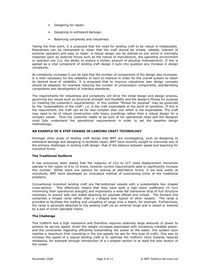
Figure 7 - Caimen-200, LCT concept © BMT Defence Services 2008 credit DefenceImaging.com
Profiling the bow section in this manner leads to a narrowing of the hull opening which in turn
restricts the type and size of cargo that can be usefully transported on the vessel. In other
situations, a profiled bow section may result in the ramp having to be located higher up from the
waterline. In situations where the ramp is in a position substantially above the waterline, the ability of the craft to be utilised in beach landing operations is negated, since this type of ramp will
require a dock or quay to effect the disembarkation of personnel or payload.
A further problem arises when beaching a craft having a keel with a v-shaped profile: the keel
edge will act as the only grounding point, leading to both transverse and longitudinal stability
problems. These problems are exacerbated if the vessel is subjected to incoming waves that are breaking obliquely on the beach. For this reason, conventional landing craft incorporate a flat-
bottomed bow section to circumnavigate the aforementioned problem.
A Solution
To increase the speed of a monohull landing craft, BMT has reviewed how the functional
requirements are distributed across the landing craft as a system.
Instead of requiring the hull to support the large payload, have a low resistance and also provide a
safe, stable beaching interface or platform; we have removed the latter requirement and placed
that on the ramp itself. This has led to the development of the Active Ramp concept. The ramp now, rather then being a passive, chain lowered flap, it is a system hydraulically actuated such
that when lowered onto the beach can exert a force through the leading edge onto the beach, thus replicating the effect of a strip of wide box shaped hull. This then allows the designer to
concentrate on optimising the hull for reduced resistance whilst still providing the required
buoyancy. An innovative hinge arrangement also allows a normal ramp/opening width to be
accommodated in the v-shaped form. This has resulted in the use of a more ship like, reduced resistance hullform for some of the recent concept designs BMT has developed.

November 2008 Page 11 of 11 © BMT Defence Services Ltd
Figure 8 - Caimen-200, LCT concept © BMT Defence Services 2008 credit DefenceImaging.com
CONCLUSION
This paper does not claim to provide the answers for the many unique challenges that designers of
landing craft will face, nor is it formed on a basis of total knowledge of these challenges. It is hoped however, that it has served to highlight some of the very real and pressing requirements for
increased effort in the understanding of landing craft design. Without this improved focus the full potential of this critical component of littoral manoeuvre capability will remain untapped.
So in answer to the question posed: “are landing craft simple ships or is it time for a rethink?” it is
proposed that there are some difficult design challenges which need addressing; many of which are unique to landing craft. These vessels may seem relatively simple in their role but a closer look
at the environment in which they operate and the evolutions they must perform shows that the designer has a number of complex challenges to overcome.


![Nmj Nov08[2]](https://img.dokumen.tips/doc/110x75/557a8b8fd8b42ac8638b4d86/nmj-nov082.jpg)


