Embed Size (px)
Citation preview

4?E <X^O\PKMO PY\
FY]RSLK
3S\$5YXNS^SYXSXQ
CbghU``Uh]cb UbX OgYf Ai]XY
Installation Manual
RRC-BP2
Black Pear II V1_00

Refrigerating and Air-Conditioning Engineers, Inc.)
Black Pear II Display Controller v1_00 Installation & Owners Manual
2 Black Pear II V1_00
Contents Warning Indications on the Air Conditioner Unit ................................................................................................. 4
Important Information .............................................................................................................................................. 5
1. Supplied Parts ...................................................................................................................................................... 6
2. Important .............................................................................................................................................................. 7
3. Product Overview ................................................................................................................................................. 8
3.1. Differences between Black Pear 1 and Black Pear 2 ................................................................................ 9
4. Connection Details .............................................................................................................................................. 10
4.1. Power Supply ........................................................................................................................................... 10
4.2. HVAC Communications Network ............................................................................................................. 10
4.3. Serial Communication Port ...................................................................................................................... 11
4.4. Digital Input / Output ................................................................................................................................ 11
4.5. USB ......................................................................................................................................................... 12
4.6. Upgrade ................................................................................................................................................... 12
4.7. Ethernet ................................................................................................................................................... 12
5. Air-Conditioning Address Configuration ............................................................................................................. 13
5.1. Toshiba Connection and Addressing Example ........................................................................................... 14
6. User Interface ..................................................................................................................................................... 15
6.1. Startup Sequence .................................................................................................................................... 15
6.2. System Overview Key ............................................................................................................................. 15
6.3. Unit Control .............................................................................................................................................. 15
6.4. Configuration Menu ................................................................................................................................. 16
6.5. Recommended Initial Setup Sequence ................................................................................................... 16
6.6. Configuration Menu Options .................................................................................................................... 17
7. Web Browser Interface ....................................................................................................................................... 18
7.1. Group View .............................................................................................................................................. 18
7.2. Unit View .................................................................................................................................................. 19
7.3. Configuration Page .................................................................................................................................. 19
8. Modbus Interface ................................................................................................................................................ 20
8.1. Port Configurations .................................................................................................................................. 20
8.2. HVAC Status and Control Registers........................................................................................................ 21
8.3. Coil Usage ............................................................................................................................................... 22
8.4. Additional Register Usage ....................................................................................................................... 22
8.5. Parameter Settings .................................................................................................................................. 23
8.5.1. Toshiba Settings for Modbus and Trend ............................................................................................ 23
8.6. Modbus Table Overview .......................................................................................................................... 24
9. Trend Interface ................................................................................................................................................... 26
9.1. Trend Process Description ...................................................................................................................... 27
9.2. Trend IQx Outstation Configuration ........................................................................................................ 28

Black Pear II Display Controller v1_00 Installation & Owners Manual
3 Black Pear II V1_00
9.3. Parameter Settings .................................................................................................................................. 28
10. BACnet Interface ................................................................................................................................................ 29
10.1. Object Types ............................................................................................................................................ 30
10.2. Service List .............................................................................................................................................. 30
10.3. Object Lists .............................................................................................................................................. 31
10.4. Toshiba Object List .................................................................................................................................. 31
10.5. Object Names .......................................................................................................................................... 33
10.6. System Objects........................................................................................................................................ 34
Appendix A: Physical Dimensions ........................................................................................................................... 35
Appendix B: Reset Button ....................................................................................................................................... 36
Appendix C: Factory Default Settings ..................................................................................................................... 37
Appendix D: Trend Outstation Memory Usage ....................................................................................................... 39
Appendix E: Error Codes ........................................................................................................................................ 40
Appendix G: Document Revision History ................................................................................................................ 43
BACnetTM is a registered trademark of ASHRAE (American Society of Heating, Refrigeration and Air-Conditioning Engineers Inc.)
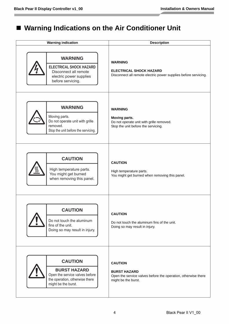
Warning Indications on the Air Conditioner Unit
Warning indication Description
WARNING
ELECTRICAL SHOCK HAZARDDisconnect all remote electric power supplies before servicing.
WARNING
Moving parts.Do not operate unit with grille removed.Stop the unit before the servicing.
CAUTION
High temperature parts.You might get burned when removing this panel.
CAUTION
Do not touch the aluminum fins of the unit.Doing so may result in injury.
CAUTION
BURST HAZARDOpen the service valves before the operation, otherwise there might be the burst.
WARNING
ELECTRICAL SHOCK HAZARDDisconnect all remote electric power supplies before servicing.
WARNING
Moving parts.Do not operate unit with grille removed.Stop the unit before the servicing.
CAUTION
High temperature parts.You might get burned when removing this panel.
CAUTION
Do not touch the aluminum fins of the unit.Doing so may result in injury.
CAUTION
BURST HAZARDOpen the service valves before the operation, otherwise there might be the burst.
Black Pear II Display Controller v1_00 Installation & Owners Manual
4 Black Pear II V1_00

For the power supply of the indoor unit, prepare the
exclusive power supply separated from that of the
outdoor unit.
Arrange the power supply, earth leakage breaker,
and main switch of the indoor unit connected to the
same outdoor unit so that they are commonly used.
Power supply wire specification : Cable 3-core
2.5mm2, in conformity with Design 60245 IEC 57.
Power supply
Power supply 220-240V —, 50Hz
Power supply switch/Earth leakage breaker or power
supply wiring/fuse rating for indoor units should be
selected by the accummulated total current values of
the indoor units.
Power supply wiring Below 50m 2.5 mm2
Control wiring, Central controller wiring
2-core with polarity wires are used for the Control
wiring between indoor unit and outdoor unit andCentral controller wiring.
To prevent noise trouble, use 2-core shield wire,
The length of the communication line means the total
length of the inter-unit wire length between indoor and
outdoor units added with the central control system
wire length
<WZY\^KX^ <XPY\WK^SYX
! 3VV OVOM^\SMKV aY\U ]RY_VN LO MK\\SON Y_^ Lc K MYWZO^OX^ ZO\]YX KXN aS\SXQ W_]^LO SX KMMY\NKXMO aS^R ^RO XK^SYXKV OVOM^\SMKV SX]^KVVK^SYX \OQ_VK^SYX]%
! 7X]_\O ^RK^ SX]^KVVK^SYX aY\U S] NYXO MY\\OM^Vc _]SXQ ^RO SXPY\WK^SYX MYX^KSXON SX^RS] WKX_KV%
! ?KUO KVV MYXXOM^SYX] ]OM_\OVc ]Y ^RK^ KXc Y_^]SNO PY\MO] KM^SXQ YX ^RO MKLVO] K\OXY^ KZZVSON ^Y ^RO ^O\WSXKV]%
! @O`O\ WYNSPc Y\ \OZKS\ ^RO 4VKMU BOK\ Lc cY_\]OVP%;bm UhhYadh hc Xc gc k]`` jc]X h\Y kUffUbhm(
! FY NS]ZY]O YP ^RS] Z\YN_M^# MYX]_V^ cY_\ NOKVO\%
WARNING1. Using the specified wires, ensure to connect the
wires, and fix wires securely so that the externaltension to the wires do not affect the connectingpart of the terminals.Incomplete connection or fixation may cause a fire,etc.
2. Be sure to connect earth wire. (grounding work)Incomplete grounding cause an electric shock. Donot connect ground wires to gas pipes, water pipes,lightning rods or ground wires for telephone wires.
3. Appliance shall be installed in accordance withnational wiring regulations.Capacity shortage of power circuit or incompleteinstallation may cause an electric shock or a fire.
CAUTION
If incorrect/incomplete wiring is carried out, it will causean electrical fire or smoke.
Be sure to install an earth leakage breaker that is nottripped by shock waves.If an earth leakage breaker is not installed, anelectric shock may be caused.
Be sure to use the cord clamps attached to theproduct.
Do not damage or scratch the conductive core andinner insulator of power and inter-connecting wireswhen peeling them.
Use the power cord and Inter-connecting wire ofspecified thickness, type, and protective devicesrequired.
Never connect 220-240V power to the terminal blocks( A , B , U1/U2, U3/U4 etc.) for control wiring(Otherwise,the system will fail).
REQUIREMENT
For power supply wiring, strictly conform to the Local
Regulation in each country.
For wiring of power supply of the outdoor units, follow
the Installation Manual of each outdoor unit.
Perform the electric wiring so that it does not come
to contact with the high-temperature part of the
pipe. The coating may melt resulting in an accident.
After connecting wires to the terminal blocks,
provide a trap and fix wires with the cord clamp.
Run the refrigerant piping line and controlwiring line in the same line.
Do not turn on the power of the indoor unit untilvacuuming of the refrigerant pipes completes.
Power supply wire and
communication wires
specifications
Power supply wire and communication wires are
procured locally.
For the power supply specifications, follow to the
table below. If capacity is little, it is dangerous
because overheat or seizure may be caused. For
specifications of the power capacity of the outdoor
unit and the power supply wires, refer to the
Installation Manual attached to the outdoor unit.
Indoor unit power supply
Black Pear II Display Controller v1_00 Installation & Owners Manual
5 Black Pear II V1_00

1. Supplied Parts
Black Pear 2
DIN-rail clips
Cat-5 ‘Straight-Through’ Ethernet cable
Black Pear II Display Controller v1_00 Installation & Owners Manual
6 Black Pear II V1_00

2. Important
All electrical work should be carried out by a competent person and wiring must be in accordance with the national electrical installation regulations.
Ensure that installation work is done correctly using the information contained in this manual.
Make all connections securely so that any outside forces acting on the cables are not applied to the terminals.
Never modify or repair the Black Pear by yourself. Any attempt to do so will void the warranty.
To dispose of this product, consult your dealer.
This unit will require setting up, using either the touch screen or the built in web browser interface.
Black Pear II Display Controller v1_00 Installation & Owners Manual
7 Black Pear II V1_00

3. Product Overview
The Black Pear 2 allows a building management system (BMS) to monitor and control air-conditioning units on a system without the need for a central controller.
It has been designed as a plug-in replacement for the original Black Pear BMS interface, with similar configuration options, all accessible via the touch screen or built-in web browser interface.
The unit incorporates a port which allows direct connection to the following system.
Manufacturer HVAC network connection Max. no. of units
64
A BMS system can communicate with the Black Pear 2 using 3 communications protocols...
1) Modbus (Modbus-RTU via RS485 and Modbus/TCP).
2) BACnet/IP
3) Trend via ethernet. (Also requires an IQ3/4 outstation with spare memory).
The Black Pear 2 can also be used on systems where a central controller is already present.
U3/U4 TCC-Link Toshiba
Black Pear II Display Controller v1_00 Installation & Owners Manual
8 Black Pear II V1_00

3.1 Differences between Black Pear 1 and Black Pear 2
One product now handles all supported HVAC manufacturers and BMS protocols.
The enclosure is approximately 5mm higher, but the width and all of the mounting holes are the same.
A 7” TFT LCD with capacitive touch is fitted as standard.
Configuration is now via the touch screen or web-browser. The PC configuration software used for Black Pear 1 is not compatible.
A real-time clock has been fitted.
A scheduler has been implemented:
- 4 separate 7-day schedules can be defined.
- 1 schedule can be assigned to each group master unit.
Modbus:
- The RS232 interface has been removed.
- A maximum of 22 slaves are used.
- ‘R/C inhibit’ registers and coils now allow individual controls to be inhibited.
BACnet:
- COV subscription is now supported. Up to 256 subscriptions can be handled.
- Error code text and error state have been added to the object list.
- Maximum APDU length supported is now 480 octets.
Black Pear II Display Controller v1_00 Installation & Owners Manual
9 Black Pear II V1_00

4. Connection Details
All electrical work should be carried out by a competent person and wiring must be in accordance with the national electrical installation regulations.
4.1 Power Supply
The Black Pear 2 requires a 24v AC supply and has a consumption not exceeding 5VA. The internal fuse is rated T630mA.
THIS EQUIPMENT MUST BE EARTHED
4.2 HVAC Communications Network
These are non-polarized, and should be connected to the HVAC communications network as per the HVAC manufacturers’ standard central controller installation instructions.
Reset Button
Power Supply
HVAC Serial Comms
Digital In/Out
24v AC
N/C
Upgrade 10/100 Base-T Ethernet
To Ethernet
RS485-B
RS485-A
Out
In
To HVAC Network
To PC for firmware upgrading.
USB
For USB memory stick
(Not currently active)
Fig. 1 Connection Details
Black Pear II Display Controller v1_00 Installation & Owners Manual
10 Black Pear II V1_00

4.3 Serial Communication Port
This connector provide access to the Modbus registers using 2-wire RS485. The port configuration is as follows:
Modbus RTU 9600 baud, 8 data bits, no parity, 1 stop bit
The RS485 interface can be used on a compatible serial communications network shared by multiple RS485 devices. The ‘Base Slave Address’ must be set to prevent multiple units using the same slave numbers.
It is recommended that screened twisted-pair cable is used. RS485-A is the non-inverting signal and is also named RS485+ RS485-B is the inverting signal and is also named RS485- The cable screen should be connected to ground at one end only.
Fig. 2 RS485 Comms Lead Wiring Diagram
4.4 Digital Input / Output
The digital input functions as the ‘Global Forced Off’ signal. This is a normally-closed, volt-free signal.
Upon detecting an ‘Open’ input, all available fancoils will be switched off and their remote-controllers will be inhibited. These settings are refreshed every 10 seconds while the input is ‘Open’.
When the input is subsequently ‘Closed’, the remote-controller inhibits are removed, but the fancoils remain off (provided a ‘Global-Off’ signal has not been generated from another source).
The digital output currently has no functionality.
Serial Comms
RS485-B
RS485-A
RS485 network
Cable screen
A B
Black Pear II Display Controller v1_00 Installation & Owners Manual
11 Black Pear II V1_00

4.5 USB
This is a standard USB-A socket for use with a USB memory stick. It is currently not active.
4.6 Upgrade
This is a standard USB-B socket and is only used for upgrading the firmware, as an alternative to using the ethernet interface.
Ensure that the correct USB driver has been installed prior to connecting the Black Pear 2 to a PC.
4.7 Ethernet
The Black Pear 2 is a 10/100Base-T half/full duplex device. It supports auto-negotiation and also features auto-crossover (Auto-MDIX), allowing the use of either a straight-through or crossover cable.
It supports either DHCP or static IP address setting. If static IP is used, then the Black Pear 2 will require the IP address, gateway address and subnet-mask configuring to match the host network it is attached to.
If the unit is only being accessed via the local network then set the gateway address to be the same as the IP address, otherwise enter
the address of the appropriate gateway or router.
Black Pear II Display Controller v1_00 Installation & Owners Manual
12 Black Pear II V1_00

5. Air-Conditioning Address Configuration
The systems need to be set up as if a manufacturer’s standard central controller is to be fitted. The Black Pear 2 can replace or work in parallel with a central controller.
Units can be grouped within the Black Pear via the HVAC configuration page. The groupings determine which unit addresses can accept commands from the BMS system.
The group number is defined as ‘the lowest indoor unit address within the group’. This then becomes the ‘master’ address for the group, and is the only address within that group that can accept commands.
The other units within a group can be classed as ‘slave’ units and contain the same status parameter values as the ‘master’, apart from Return Air Temp and Error Code, which are unique to each unit.
Attempting to write a command to a ‘slave’ unit will have no effect.
If you wish to be able to monitor slave units within a group, ensure that they are configured as individual units (via the A/C system) and grouped using the Black Pear.
Black Pear II Display Controller v1_00 Installation & Owners Manual
13 Black Pear II V1_00

5.1 Toshiba Connection and Addressing Example
Connect to outdoor unit terminals U3 and U4, as per a standard central controller.
Fig. 6 Toshiba Wiring Example
VRF Outdoor (System
Address 1)
Indoor Unit (DN 03 = 1)
Indoor Unit (DN 03 = 2)
Indoor Unit (DN 03 = 3)
VRF Outdoor (System
Address 2)
Indoor Unit (DN 03 = 4)
Indoor Unit (DN 03 = 5)
Indoor Unit (DN 03 = 6)
Split System Indoor Unit
(System Address 3 DN 03 = 7)
Black Pear 2
U1/U2
U1/U2
U3/U4
U3/U4
*TCB-PCNT30TLE2 Network Adapter required for some Split Indoor units.
Each refrigerant system must have a separate line address and the network address (Configuration Item 03) must be set between 1 and 64. If units are grouped via AB, the units will have the same network address and the status data for the follower units will not be available.
Black Pear II Display Controller v1_00 Installation & Owners Manual
14 Black Pear II V1_00

6. User Interface
6.1 Startup Sequence
6.2 System Overview Key
01 Unit Off (red unit number)
02 Unit On (green unit number)
Master unit (dark blue background)
Slave unit (light blue background)
Unit has not been detected (grey button)
Unit in error (flashing red outline)
Display Configuration Menu UU = Unit number gg = Group number
6.3 Unit Control
Tapping a detected unit will display the manual control screen. The control options visible will depend on the type of unit selected.
Tap the page curls to show the next/previous detected unit. Tap the green arrow to return to the system overview screen.
Shortly after power-up or a system reset, the system overview page appears, ready to start the initial HVAC scan.
After a short delay, the scan will start.
Once the scan has completed, the overview screen will look like this. All units found during the scan will be highlighted on the grid, in various colours.
UU gg
Black Pear II Display Controller v1_00 Installation & Owners Manual
15 Black Pear II V1_00

6.4 Configuration Menu
Restore Restore factory defaults.
Protocol Configure BMS protocols.
Date and Time Set clock and network time server.
HVAC Configure HVAC interface and groupings.
Schedule Create schedules and attach to groups.
Unit Names Change unit names.
Security Set pin code.
Web Server Configure web interface.
Error Log View list of alarms detected
Information Show firmware details.
Diagnostics Show various diagnostic info.
Reboot Perform a system reset. This is recommended after any changes to the configuration.
Network Setup ethernet interface.
Pin Code Required Indicates options requiring the pin code. Once the correct pin has been entered, it will not need re-entering until the configuration button is pressed on the system overview screen.
Factory default pin code: 0000
6.5 Recommended Initial Setup Sequence
1) Configure HVAC Select manufacturer. Configure unit groupings and global-off functionality.
2) Configure network Select DHCP or Static IP If Static IP, enter IP address, gateway address, subnet mask and DNS addresses.
3) Select BMS protocol Enable and setup required protocol (Note: Modbus is always enabled).
4) Set date and time Set the clock manually or use the network time feature to automatically set it.
5) Reboot This is always recommended after making changes to the configuration.
Black Pear II Display Controller v1_00 Installation & Owners Manual
16 Black Pear II V1_00

6.6 Configuration Menu Options
Below is a list of the configuration menu entries, together with a brief description of the settings and information that are available.
The configuration pages accessed via the web browser interface give a little bit more information about each item.
Restore Reload Factory Defaults (see Appendix C for details)
Date and Time Set Data & Time manually Setup Network Time Server for automatic time setting
Schedule Edit Schedules Assign Schedules to Groups
Security Set Pin Code
Error Log View Error History (not retained through power-outage or reboot)
Diagnostics Show information for Ethernet, Trend, BACnet and webserver
Network Set Device/Hostname Enable DHCP or set Static IP address
Protocol Configure BACnet, Trend and Modbus interfaces
HVAC Set HVAC manufacturer Set Unit groupings Enable/Disable Global-Off for each group Set R/C inhibit for each group
Unit Names Alter unit names (used on-screen and by BACnet)
Web Server Enable/disable webserver interface Alter TCP port number used
Information Firmware/Hardware version information BMS protocol enable/disable status
Reboot Force the Black Pear 2 to restart (recommended after altering configuration)
Black Pear II Display Controller v1_00 Installation & Owners Manual
17 Black Pear II V1_00
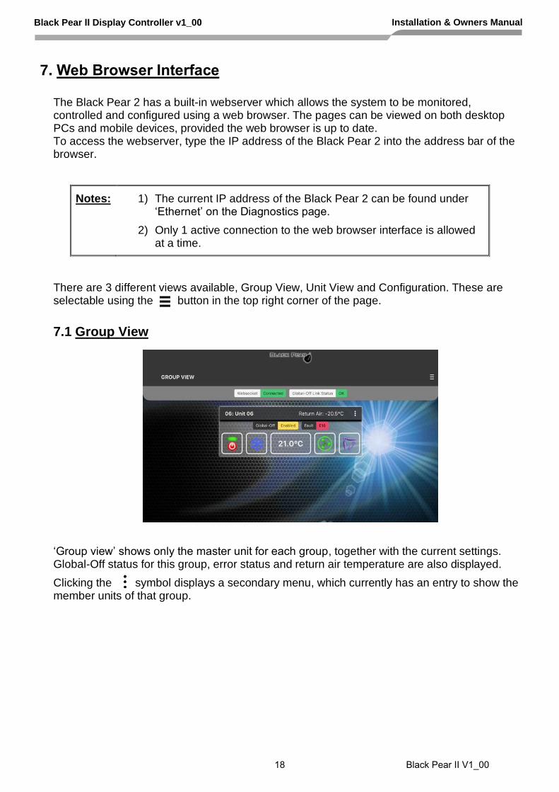
7. Web Browser Interface
The Black Pear 2 has a built-in webserver which allows the system to be monitored, controlled and configured using a web browser. The pages can be viewed on both desktop PCs and mobile devices, provided the web browser is up to date. To access the webserver, type the IP address of the Black Pear 2 into the address bar of the browser.
Notes: 1) The current IP address of the Black Pear 2 can be found under ‘Ethernet’ on the Diagnostics page.
2) Only 1 active connection to the web browser interface is allowed at a time.
There are 3 different views available, Group View, Unit View and Configuration. These are selectable using the button in the top right corner of the page.
7.1 Group View
‘Group view’ shows only the master unit for each group, together with the current settings. Global-Off status for this group, error status and return air temperature are also displayed.
Clicking the symbol displays a secondary menu, which currently has an entry to show the member units of that group.
Black Pear II Display Controller v1_00 Installation & Owners Manual
18 Black Pear II V1_00

7.2 Unit View
‘Unit view’ shows an overview of the HVAC system, highlighting all the units that have been detected.
Clicking on a detected unit displays the current status of that unit, and whether or not it is a group master. The settings can only be changed if the unit is a group master.
7.3 Configuration Page
The configuration menu will either be on the left or across the top, depending on the width of the web browser page.
Note: After making changes on a page, click the ‘Save’ button at the bottom of the page to update the Black Pear 2 settings.
When configuration is complete, click the ‘Reboot’ button on the ‘Reset System’ page.
Black Pear II Display Controller v1_00 Installation & Owners Manual
19 Black Pear II V1_00

8. Modbus Interface
8.1 Port Configurations
RS485 interface Modbus RTU 9600 baud, 8 data bits, no parity, 1 stop bit
Network interface Modbus/TCP 2 simultaneous Modbus/TCP client connections are supported: 1 only uses TCP port 502 (default Modbus/TCP port) 2 uses a user configurable TCP port number
Modbus functions supported Fn 1 Read Coils Fn 3 Read Holding Registers Fn 5 Write Single Coil Fn 6 Write Single Register Fn 16 Write Multiple Registers (Max. 16 registers at once)
RS485
Black Pear 2
Outdoor Units Indoor Units
Modbus RTU BMS
System
Serial Comms cable
(Not supplied)
Ethernet
Modbus/TCP BMS
System
Cat-5 cable (Supplied)
HVAC Network
Fig. 7 Modbus System Example
Black Pear II Display Controller v1_00 Installation & Owners Manual
20 Black Pear II V1_00

8.2 HVAC Status and Control Registers
The Black Pear 2 behaves as 22 modbus slaves. Each slave contains 90 registers (Offset = 0 to 89).
The default ‘Base Slave Address’ is 1, meaning the Black Pear will respond to msgs for slaves 1 to 22. The Base Slave Address can be adjusted from 1 up to 200. A setting of 200 means the Black Pear will respond to msgs for slaves 200 to 221. This is useful to prevent address clashing when the Black Pear unit is attached to a serial communications network containing multiple Modbus devices.
Some BMS systems have limited slave address resources, so the ‘Single Slave Access’ feature means the Black Pear can be configured to respond to just 1 slave address (i.e. the ‘Base Slave Address’ setting).
The Black Pear maps the data from the air conditioner units into Modbus registers accessed by two Modbus parameters ‘Slave No.’ and ‘Offset’.
All slave numbers referred to in this document assume the default Base Address.
On a system with a maximum of 50 units, slaves 1 to 16 each represent 3 units (A,B & C), and slave 17 represents 2 units (A & B). On a system with a maximum of 64 units, slaves 1 to 21 each represent 3 units (A,B & C), and slave 22 represents 1 unit (A). Each slave is organised as follows:
General Information Extended Information Extra Information
Unit A Unit B Unit C Unit A Unit B Unit C Unit A Unit B Unit C
Offset 0 Offset 10 Offset 20 Offset 30 Offset 40 Offset 50 Offset 60 Offset 70 Offset 80
General information for a
single unit Extended information for a
single unit Extra information for a
single unit Register Offset
Stored Value Register Offset
Stored Value Register Offset
Stored Value
0 Return Air Temp 0 Air Direction (R) 0 ‘Hi-res’ Return Air
1 Error Code 1 Air Direction (W) 1 ‘Hi-res’ Setpoint (R)
2 Setpoint (R) 2 R/C Inhibit (R) 2 ‘Hi-res’ Setpoint (W)
3 Mode (R) 3 R/C Inhibit (W) 3 Unused
4 Fan Speed (R) 4 Ventilation (R) 4 Unused
5 Setpoint (W) 5 Ventilation (W) 5 Unused
6 Mode (W) 6 Error Code (DispA) 6 Unused
7 Fan Speed (W) 7 Error Code (DispB) 7 Unused
8 On/Off (R) 8 Reserved 8 Unused
9 On/Off (W) 9 Unused 9 Unused
See Section 8.6 for an overview of Modbus slave and offset usage.
Examples: 1) To read the current fan speed of unit 8
Single Slave Access = Off Single Slave Access = On
Slave Function Offset Slave Function Offset
3 3 14 1 3 194
2) To read the current mode of unit 48
Single Slave Access = Off Single Slave Access = On
Slave Function Offset Slave Function Offset
16 3 23 1 3 1373
Not currently supported
Black Pear II Display Controller v1_00 Installation & Owners Manual
21 Black Pear II V1_00

8.3 Coil Usage
On/Off, inhibits and error status can also be accessed via ‘Coils’. The inhibits can be controlled all at once or individually.
Each slave contains 48 coils, organised as follows:
Coil Offset Definition
0 Unit A On/Off (R)
1 Unit A On/Off (W)
2 Unit B On/Off (R)
3 Unit B On/Off (W)
4 Unit C On/Off (R)
5 Unit C On/Off (W)
6 Unit A Inhibit Any (R)
7 Unit A Inhibit All (W)
8 Unit B Inhibit Any (R)
9 Unit B Inhibit All (W)
10 Unit C Inhibit Any (R)
11 Unit C Inhibit All (W)
12 Unit A Inhibit On/Off (R)
13 Unit A Inhibit On/Off (W)
14 Unit B Inhibit On/Off (R)
15 Unit B Inhibit On/Off (W)
16 Unit C Inhibit On/Off (R)
17 Unit C Inhibit On/Off (W)
18 Unit A Inhibit Mode (R)
19 Unit A Inhibit Mode (W)
20 Unit B Inhibit Mode (R)
21 Unit B Inhibit Mode (W)
22 Unit C Inhibit Mode (R)
23 Unit C Inhibit Mode (W)
Coil Offset Definition
24 Unit A Inhibit Setpoint (R)
25 Unit A Inhibit Setpoint (W)
26 Unit B Inhibit Setpoint (R)
27 Unit B Inhibit Setpoint (W)
28 Unit C Inhibit Setpoint (R)
29 Unit C Inhibit Setpoint (W)
30 Unit A Inhibit Fan Speed (R)
31 Unit A Inhibit Fan Speed (W)
32 Unit B Inhibit Fan Speed (R)
33 Unit B Inhibit Fan Speed (W)
34 Unit C Inhibit Fan Speed (R)
35 Unit C Inhibit Fan Speed (W)
36 Unit A Inhibit Air Dir (R)
37 Unit A Inhibit Air Dir (W)
38 Unit B Inhibit Air Dir (R)
39 Unit B Inhibit Air Dir (W)
40 Unit C Inhibit Air Dir (R)
41 Unit C Inhibit Air Dir (W)
42 Unit A Error Status (R)
43 Not used
44 Unit B Error Status (R)
45 Not used
46 Unit C Error Status (R)
47 Not used
Note Coil access is not available when ‘Single Slave Access’ is enabled.
8.4 Additional Register Usage
Slave Offset Single Slave Offset
Description Valid Settings
22 20 1910 HVAC Network Status 00: Waiting 01: Searching 02: Ready 03: Unknown
22 21 1911 System Force Off 00: Not active 01: Active
See Section 10.5 for a description of these additional registers.
Black Pear II Display Controller v1_00 Installation & Owners Manual
22 Black Pear II V1_00

Toshiba Settings for Modbus and Trend
Parameter Settings Notes
Return Air Temperature -35ºC to 92ºC Read-only
‘Hi-res’ Return Air -35.0ºC to 92.0ºC register contains the value multiplied by 10. eg. 235 = 23.5ºC
Error Code 4 digit error code where 8000 = ‘No Error’ 6999 = ‘Unit Not Present’
Read-only See Appendix D
Setpoint Temperature 18ºC to 29ºC
‘Hi-res’ Setpoint 18.0ºC to 29.0ºC register contains the value multiplied by 10. eg. 255 = 25.5ºC
Operation Mode 00: Fan (Draft) 01: Cool 02: Heat 03: Dry 04: Auto 05: (Not Used)
06: AutoCool 07: AutoHeat
Not settable
08: Heat Exchange 09: VN-Auto 10: VN-Bypass
VN units only
Fan Speed 00: Low 01: Medium 02: High 03: Auto
On/Off 00: Off 01: On
Air Direction 00: Horizontal
01: 22½ deg
02: 45 deg
03: 67½ deg
04: Vertical 05: Swing 06: Hold
Local R/C Inhibit 00: No inhibited controls 01: On/Off 02: Mode 04: Setpoint 08: Fan Speed 16: Air Direction
Individual inhibits can be combined by adding settings together. eg. Inhibit All = 31
8.5.1
8.5 Parameter Settings
Black Pear II Display Controller v1_00 Installation & Owners Manual
23 Black Pear II V1_00

8.6 Modbus Table Overview
Unit Address
Slave General Info Base
Offset
Extended Info Base
Offset
Extra Info Base Offset
Single Slave Access Coil Base Offsets
General Info Base
Offset
Extended Info Base
Offset
On/Off Inhibit
1 1 0 30 60 0 30 0 6
2 1 10 40 70 10 40 2 8
3 1 20 50 80 20 50 4 10
4 2 0 30 60 90 120 0 6
5 2 10 40 70 100 130 2 8
6 2 20 50 80 110 140 4 10
7 3 0 30 60 180 210 0 6
8 3 10 40 70 190 220 2 8
9 3 20 50 80 200 230 4 10
10 4 0 30 60 270 300 0 6
11 4 10 40 70 280 310 2 8
12 4 20 50 80 290 320 4 10
13 5 0 30 60 360 390 0 6
14 5 10 40 70 370 400 2 8
15 5 20 50 80 380 410 4 10
16 6 0 30 60 450 480 0 6
17 6 10 40 70 460 490 2 8
18 6 20 50 80 470 500 4 10
19 7 0 30 60 540 570 0 6
20 7 10 40 70 550 580 2 8
21 7 20 50 80 560 590 4 10
22 8 0 30 60 630 660 0 6
23 8 10 40 70 640 670 2 8
24 8 20 50 80 650 680 4 10
25 9 0 30 60 720 750 0 6
26 9 10 40 70 730 760 2 8
27 9 20 50 80 740 770 4 10
28 10 0 30 60 810 840 0 6
29 10 10 40 70 820 850 2 8
30 10 20 50 80 830 860 4 10
31 11 0 30 60 900 930 0 6
32 11 10 40 70 910 940 2 8
33 11 20 50 80 920 950 4 10
34 12 0 30 60 990 1020 0 6
35 12 10 40 70 1000 1030 2 8
36 12 20 50 80 1010 1040 4 10
37 13 0 30 60 1080 1110 0 6
38 13 10 40 70 1090 1120 2 8
39 13 20 50 80 1100 1130 4 10
40 14 0 30 60 1170 1200 0 6
41 14 10 40 70 1180 1210 2 8
42 14 20 50 80 1190 1220 4 10
43 15 0 30 60 1260 1290 0 6
44 15 10 40 70 1270 1300 2 8
45 15 20 50 80 1280 1310 4 10
46 16 0 30 60 1350 1380 0 6
47 16 10 40 70 1360 1390 2 8
48 16 20 50 80 1370 1400 4 10
Black Pear II Display Controller v1_00 Installation & Owners Manual
24 Black Pear II V1_00

Unit
Address Slave General
Info Base Offset
Extended Info Base
Offset
Extra Info Base Offset
Single Slave Access Coil Base Offsets
General Info Base
Offset
Extended Info Base
Offset
On/Off Inhibit
53 18 10 40 70 1540 1570 2 8
54 18 20 50 80 1550 1580 4 10
55 19 0 30 60 1620 1650 0 6
56 19 10 40 70 1630 1660 2 8
57 19 20 50 80 1640 1670 4 10
58 20 0 30 60 1710 1740 0 6
59 20 10 40 70 1720 1750 2 8
60 20 20 50 80 1730 1760 4 10
61 21 0 30 60 1800 1830 0 6
62 21 10 40 70 1810 1840 2 8
63 21 20 50 80 1820 1850 4 10
64 22 0 30 60 1890 1920 0 6
49 17 0 30 60 1440 1470 0 6
50 17 10 40 70 1450 1480 2 8
51 17 20 50 80 1460 1490 4 10
52 18 0 30 60 1530 1560 0 6
Black Pear II Display Controller v1_00 Installation & Owners Manual
25 Black Pear II V1_00

9. Trend Interface
The Black Pear connects via Ethernet to a CNC or the virtual CNC port of a Trend IQ outstation, and uses sensors, switches and knobs defined in the IQx memory to mirror a range of HVAC parameters, making them available on a Trend network.
Black Pear 2
Outdoor Units Indoor Units
Ethernet
Trend IQx Outstation with vCNC
Cat-5 cable (Supplied)
HVAC Network
Trend Supervisor
Fig. 8 Trend System Example
Black Pear II Display Controller v1_00 Installation & Owners Manual
26 Black Pear II V1_00

9.1 Trend Process Description
Startup Sequence 1) Power up 2) Waiting for initial scan 3) Perform initial HVAC scan 4) Initial scan complete 5) Connect to CNC port 6) Transfer current HVAC status to required Trend outstation (“First Pass”) 7) Disconnect from CNC port 8) Wait for re-connection time 9) Connect to CNC port 10) Poll the objects for each active HVAC unit in the Trend outstation, then either Update the HVAC if the value of a Trend object has been altered, or Update the Trend object if the value of an HVAC parameter has changed. 11) Disconnect from CNC port 12) Wait for re-connection time 13) Goto 9
At power-up, the Black Pear will wait for the initial HVAC scan to begin. During this scan, all available ‘active’ HVAC units are discovered. Once the scan is complete, the Black Pear will transfer all current parameter settings to the appropriate objects in the destination Trend outstation. This process is called the ‘First Pass’. This ensures that the values in the Black Pear and the Trend device are in sync. Until the ‘First Pass’ is complete, all commands sent from the Trend network to the Black Pear will be ignored.
The re-connection time is calculated from the CNC Usage setting within the Black Pear. This ensures that all Black Pear devices sharing a single CNC have enough time to connect.
Notes:
Some Trend systems will generate ‘network alarms’ due to the repeated connection and disconnection of the Black Pear to the CNC. Setting the CNC Usage = 0 will allow a single Black Pear to remain connected to the CNC, thus preventing these alarms from being generated.
Following a reconfiguration of the Trend outstation, it is important that the Black Pear is restarted, to guarantee that all parameters are
in sync.
Black Pear II Display Controller v1_00 Installation & Owners Manual
27 Black Pear II V1_00

9.2 Trend IQx Outstation Configuration
3 sensors, 2 switches and 4 knobs are required to store all the parameters for a single unit.
The table below shows how to calculate the number of each object required :
Fan Coil Parameter
Sensor No. Switch No. Knob No.
Return Air S+((FC-1)*3)
Error Code S+((FC-1)*3)+1
{HVAC specific} S+((FC-1)*3)+2
On/Off W+((FC-1)*2)
Inhibit W+((FC-1)*2)+1
Setpoint K+((FC-1)*4)
Mode K+((FC-1)*4)+1
Fan Speed K+((FC-1)*4)+2
Air Direction K+((FC-1)*4)+3
where FC = Fan Coil Address (1 to 64) S = Sensor Base Address W = Switch Base Address These are configurable K = Knob Base Address E.g. If Sensor Base Address = 100 Switch Base Address = 50 Knob Base Address = 50
then the following table shows the object numbers required for addresses 1,2,50,63 and 64.
FC 1 FC 2 … FC 50 … FC 63 FC 64
Sensors 100 to 101 103 to 104 … 247 to 249 … 286 to 287 289 to 290
Switches 50 to 51 52 to 53 … 148 to 149 … 174 to 175 176 to 177
Knobs 50 to 53 54 to 57 … 246 to 249 … 298 to 301 302 to 305
The Black Pear can be configured to enable only those objects of interest to the user, therefore reducing the memory overhead required in the IQ outstation. Any objects enabled in the Black Pear which aren’t defined in the Trend outstation will simply be ignored during the polling sequence. Note that this does not change the sensor, switch and knob numbers associated with each HVAC parameter.
If a sensor has been added to the sequence table then its ‘Value’ output must be connected to its ‘Source Value’ input, otherwise it will
return a reading of zero.
See Appendix D for details of the memory requirements in the Trend outstation.
}
Black Pear II Display Controller v1_00 Installation & Owners Manual
9.3 Parameter Settings
See the tables in Section 8.5 for a list of valid parameter settings.
28 Black Pear II V1_00

10. BACnet Interface
The BLACK Pear 2 is designed to work with a BACnet/IP network as described in the ANSI/ASHRAE Standard 135-2010.
Property Setting
Segmentation Not Supported
Maximum APDU length supported 480 octets
Object List Supported
Device ID User settable
Device Name User settable
Object Names User settable
Maximum COV subscriptions 256
Black Pear 2
Outdoor Units Indoor Units
BACnet / IP
Ethernet
BACnet BMS
System
Cat-5 cable (Supplied)
HVAC Network
Fig. 9 BACnet System Example
Black Pear II Display Controller v1_00 Installation & Owners Manual
29 Black Pear II V1_00

10.1 Object Types
Object Type Supported
Analog Input 0 Yes
Analog Output 1 Yes
Analog Value 2
Binary Input 3 Yes
Binary Output 4 Yes
Binary Value 5 Yes
Calendar 6
Command 7
Device 8 Yes
Event Enrollment 9
File 10
Group 11
Loop 12
Multi-State Input 13 Yes
Multi-State Output 14 Yes
Notification Class 15
Program 16
Schedule 17
Averaging 18
Multi-State Value 19
Trend Log 20
CharacterString Value 40 Yes
10.2 Service List
Supported Services Notes
Confirmed COV Notification 1
Subscribe COV 5
Read Property 12
Read Property Multiple 14
Write Property 15
Write Property Multiple 16
Device Communication Control 17
Re-Initialize Device 20 Only ‘ColdStart’ implemented
I-Have 27
Unconfirmed COV Notification 28
Who-Has 33
Who-Is 34
I-Am 36
Black Pear II Display Controller v1_00 Installation & Owners Manual
30 Black Pear II V1_00

10.3.1 Toshiba Object List
Object Object Type Instance No.
‘Present Value’ Settings
Notes
On/Off (Setup) Binary Output 1xxx01 Inactive: Off Active: On
On/Off (State) Binary Input 1xxx02 Inactive: Off Active: On
Error Code Analog Input 1xxx03 4 digit error code where 8000= ‘No Error’ 6999= ‘Unit Not Present’
See Appendix F
Operation Mode (Setup) Multi-State Output 1xxx04 01: Fan 02: Cool 03: Heat 04: Dry 05: Auto 06: N/A
07: Auto Cool 08: Auto Heat
Not settable
09: Heat Exchange 10: VN-Auto 11: VN-Bypass
VN units only
Operation Mode (State) Multi-State Input 1xxx05 01: Fan 02: Cool 03: Heat 04: Dry 05: Auto 06: N/A
07: Auto Cool 08: Auto Heat
09: Heat Exchange 10: VN-Auto 11: VN-Bypass
VN units only
Fan Speed (Setup) Multi-State Output 1xxx06 01: Low 02: Medium 03: High 04: Auto
Fan Speed (State) Multi-State Input 1xxx07 01: Low 02: Medium 03: High 04: Auto
Room Temperature Analog Input 1xxx08 -35.0ºC to 92.0ºC
Setpoint Temperature (Setup)
Analog Output 1xxx09 18.0ºC to 29.0ºC
Setpoint Temperature (State)
Analog Input 1xxx10 18.0ºC to 29.0ºC
10.3 Object Lists
Black Pear II Display Controller v1_00 Installation & Owners Manual
31 Black Pear II V1_00

Object Object Type Instance No.
‘Present Value’ Settings
Notes
Air Direction (State) Multi-State Input 1xxx14 01: Horizontal 02: 22½ deg 03: 45 deg 04: 67½ deg 05: Vertical 06: Swing 07: Hold
(Unused) 1xxx15
(Unused) 1xxx16
{HVAC Specific} Analog Input 1xxx17
Error Code Text CharacterString Value
1xxx18 HVAC Manufacturers’ Error Code
Error State Binary Input 1xxx19 Inactive: Ok Active: In Error
(Unused) 1xxx20
(Unused) 1xxx21
(Unused) 1xxx22
HVAC Network Status Multi-State Input 100023 01: Waiting 02: Searching 03: Ready 04: Unknown
System Force Off Binary Value 100024 Inactive: Off Active: On
Device Device zzz zzz = 1 to 4194302
where xxx represents unit address 001 to 064
Local R/C Inhibit (Setup) Binary Output 1xxx11 Inactive: Off Active: Inhibit
Local R/C Inhibit (State) Binary Input 1xxx12 Inactive: Off Active: Inhibited
Air Direction (Setup) Multi-State Output 1xxx13 01: Horizontal 02: 22½ deg 03: 45 deg 04: 67½ deg 05: Vertical 06: Swing 07: Hold
Black Pear II Display Controller v1_00 Installation & Owners Manual
32 Black Pear II V1_00

10.4 Object Names
Object Object Name Notes
On/Off (Setup) nnn (ON_w)
On/Off (State) nnn (ON_r)
Error Code nnn (ECode)
Operation Mode (Setup) nnn (MD_w)
Operation Mode (State) nnn (MD_r)
Fan Speed (Setup) nnn (FS_w)
Fan Speed (State) nnn (FS_r)
Room Temperature nnn (RA)
Setpoint Temperature (Setup) nnn (SP_w)
Setpoint Temperature (State) nnn (SP_r)
Local Inhibit (Setup) nnn (LI_w
Local Inhibit (State) nnn (LI_r)
Air Direction (Setup) nnn (AD_w)
Air Direction (State) nnn (AD_r)
Error Code Text nnn (Error Text)
Error State nnn (Error State)
HVAC Network Status Sys_HVAC_Network_Status
System Force Off Sys_Force_Off
where ‘nnn’ is the unit name entered via the ‘Unit Name’ configuration page.
Notes:
Setting the setpoint to 1 dp is reliant on the HVAC unit accepting setpoint commands to this resolution.
Black Pear II Display Controller v1_00 Installation & Owners Manual
33 Black Pear II V1_00

10.5 System Objects
There are 2 ‘System’ objects contained within the Black Pear, which are classed as global objects. A description of each is detailed below.
System Object Description
HVAC Network Status Read-only object providing an indication of the communication status between the Black Pear and the HVAC network. The various states are defined as follows: Waiting: The Black Pear has been restarted and is preparing to start scanning the HVAC network. Searching: The Black Pear is performing its initial scan of the HVAC network, looking for active units within the allowable address range. Ready: The initial scan is complete and the Black Pear will now accept new commands. Unknown: An undefined state has been detected. Note:
Until the status = ‘Ready’, commands send to the Black Pear will be ignored.
System Force Off Writeable object to enable and disable the ‘global off’ command.
Black Pear II Display Controller v1_00 Installation & Owners Manual
34 Black Pear II V1_00

Appendix A : Physical Dimensions
The holes marked ‘A’ should be used when mounting the enclosure on a back panel.
The holes marked ‘B’ can be used to attach the supplied din-rail clips.
122mm
Reset Button
Power Supply
HVAC Serial Comms
USB Upgrade 10/100 Base-T Ethernet
210mm
202mm
39mm
A
A
A
A
B
B
B
B
91mm
Digital In/Out
Fig. 10 Dimensions
Black Pear II Display Controller v1_00 Installation & Owners Manual
35 Black Pear II V1_00

Appendix B : Reset Button
The Reset Button currently only has 1 function :
1) To force the unit into ‘bootloader’ mode ready for a firmware update.
Function 1 – Enable ‘Bootloader’ Mode
Bootloader mode allows the firmware to be updated from a PC.
Press and hold in the reset button while powering up the unit. Continue to hold in the reset button for approx. 5 seconds, until the bootloader screen appears. The unit is now in bootloader mode.
Note: Enabling the bootloader in this way is only necessary if
a) the firmware update software fails to automatically put the unit into bootloader mode, or
b) the application program is somehow corrupted and will not boot.
Black Pear II Display Controller v1_00 Installation & Owners Manual
36 Black Pear II V1_00
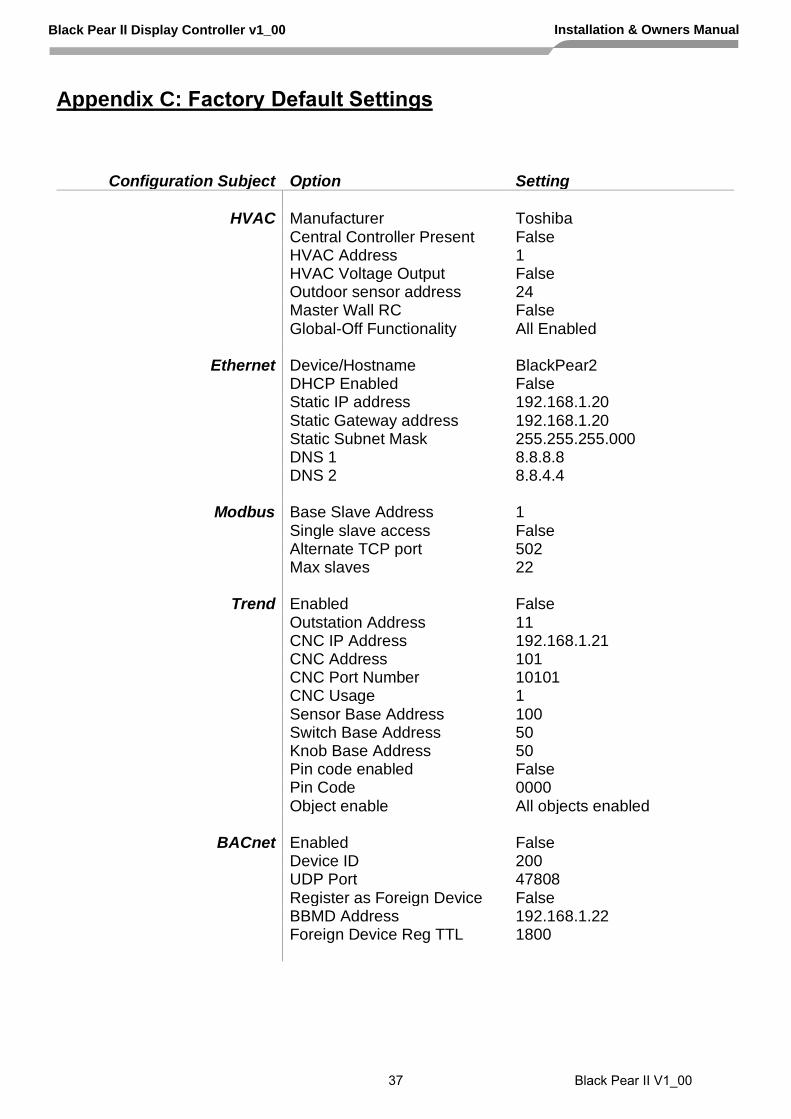
Appendix C: Factory Default Settings
Configuration Subject Option Setting
HVAC Manufacturer Toshiba
Central Controller Present False HVAC Address 1 HVAC Voltage Output False Outdoor sensor address 24 Master Wall RC False Global-Off Functionality All Enabled
Ethernet Device/Hostname BlackPear2 DHCP Enabled False Static IP address 192.168.1.20 Static Gateway address 192.168.1.20 Static Subnet Mask 255.255.255.000 DNS 1 8.8.8.8 DNS 2 8.8.4.4
Modbus Base Slave Address 1 Single slave access False Alternate TCP port 502 Max slaves 22
Trend Enabled False Outstation Address 11 CNC IP Address 192.168.1.21 CNC Address 101 CNC Port Number 10101 CNC Usage 1 Sensor Base Address 100 Switch Base Address 50 Knob Base Address 50 Pin code enabled False Pin Code 0000 Object enable All objects enabled
BACnet Enabled False Device ID 200 UDP Port 47808 Register as Foreign Device False BBMD Address 192.168.1.22 Foreign Device Reg TTL 1800
Black Pear II Display Controller v1_00 Installation & Owners Manual
37 Black Pear II V1_00

Configuration Subject Option Setting
Unit Names Unit 1 ‘Unit 1’
Unit 2 ‘Unit 2’ Unit 64 ‘Unit 64’
Unit Groups Unit 1 Group 1 Unit 2 Group 2 Unit 64 Group 64
Scheduler Enabled False Scheduled Events None defined
Date and Time Enable SNTP False
Time Server time.google.com Poll Once False
Security Admin Pin code 0000
Black Pear II Display Controller v1_00 Installation & Owners Manual
38 Black Pear II V1_00

Appendix D : Trend Outstation Memory Usage
1) The table below shows how much memory (in brIQs) each parameter requires :
Parameter Trend Module Size (brIQs) Comments
Return Air Temp Sensor 76
Error Code Sensor 76
On/Off Switch 10
Inhibit Switch 10
Setpoint Knob 13
Mode Knob 13
Fan Speed Knob 13
Air Direction Knob 13
2) A Trend IQ3 has a capacity of 10000 to 45000 brIQs depending on the model and an IQ41x has a capacity of 10000 brIQs.
3) This table shows the number of brIQs needed for various system sizes and parameter requirements:
Parameter Usage brIQs per FC
16 FC system
32 FC system
50 FC system
64 FC system
All common parameters
224 3584 7168 11200 14336
Return Air Error Code
152 2432 4864 7600 9728
Return Air Error code On/Off Setpoint
175 2800 5600 8750 11200
Return Air Error Code On/Off Inhibit Setpoint Mode Fan Speed
211 3376 6752 10550 13504
IQ3xcite IQ3xact IQ3xcite IQ41x
I/O Max 0 12 16 96 128
IQ3 brIQs - 10,000 30,000 30,000 37,000 -
IQ3/XNC brIQs 45,000 20,000 - 45,000 - -
IQ41x brIQs 10,000
Black Pear II Display Controller v1_00 Installation & Owners Manual
39 Black Pear II V1_00
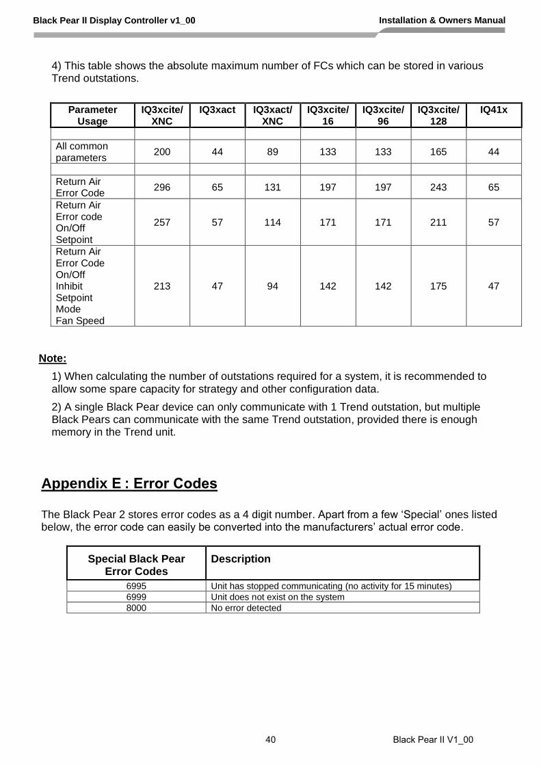
4) This table shows the absolute maximum number of FCs which can be stored in various Trend outstations.
Parameter Usage
IQ3xcite/XNC
IQ3xact IQ3xact/XNC
IQ3xcite/16
IQ3xcite/96
IQ3xcite/128
IQ41x
All common parameters
200 44 89 133 133 165 44
Return Air Error Code
296 65 131 197 197 243 65
Return Air Error code On/Off Setpoint
257 57 114 171 171 211 57
Return Air Error Code On/Off Inhibit Setpoint Mode Fan Speed
213 47 94 142 142 175 47
Note:
1) When calculating the number of outstations required for a system, it is recommended to allow some spare capacity for strategy and other configuration data.
2) A single Black Pear device can only communicate with 1 Trend outstation, but multiple Black Pears can communicate with the same Trend outstation, provided there is enough memory in the Trend unit.
Black Pear II Display Controller v1_00 Installation & Owners Manual
Appendix E : Error Codes
The Black Pear 2 stores error codes as a 4 digit number. Apart from a few ‘Special’ ones listed below, the error code can easily be converted into the manufacturers’ actual error code.
Special Black Pear Error Codes
Description
6995 Unit has stopped communicating (no activity for 15 minutes)
6999 Unit does not exist on the system
8000 No error detected
40 Black Pear II V1_00

Toshiba Cross Reference
Black Pear Error Code
Toshiba Error Code
Description
1005 C05 Sending error in TCC-LINK central control device
1006 C06 Receiving error in TCC-LINK central control device
1012 C12 Batch alarm of general-purpose equipment control interface
2001 E01 Communication error between indoor and remote controller
(Detected at remote controller side)
2002 E02 Sending error of remote controller
2003 E03 Communication error between indoor and remote controller (Detected at indoor side)
2004 E04 Communication circuit error between indoor and outdoor (Detected at indoor side)
2006 E06 Decrease of No. of indoor units
2007 E07 Communication circuit error between indoor/outdoor (Detected at outdoor side)
2008 E08 Duplicated indoor addresses
2009 E09 Duplicated master remote controllers
2010 E10 Communication error between indoor P.C.board
2012 E12 Automatic address start error
2015 E15 No indoor automatic address
2016 E16 Capacity over / No. of connected indoor units
2018 E18 Communication error between indoor header and follower units
2019 E19 Outdoor header units quantity error
2020 E20 Other line connected during automatic address
2023 E23 Sending error in communication between outdoor units
2025 E25 Duplicated follower outdoor address
2026 E26 Decrease of No. of connected outdoor units
2028 E28 Follower outdoor unit error
2031 E31 IPDU communication error
3001 F01 Indoor TCJ sensor error
3002 F02 Indoor TC2 sensor error
3003 F03 Indoor TC1 sensor error
3004 F04 TD1 sensor error
3005 F05 TD2 sensor error
3006 F06 TE1 sensor error
3007 F07 TL sensor error
3008 F08 TO sensor error
3010 F10 TA sensor error
3012 F12 TS1 sensor error
3013 F13 TH sensor error
3015 F15 Outdoor temp. sensor misconnection (TE1,TL)
3016 F16 Outdoor pressure sensor misconnection (Pd,Ps)
3023 F23 Ps sensor error
3024 F24 Pd sensor error
3029 F29 Indoor other error
3031 F31 Outdoor EEPROM error
4001 H01 Compressor break down
4002 H02 Magnet switch error / Overcurrent relay operation / Compressor error (lock)
4003 H03 Current detection circuit error
4004 H04 Comp-1 case thermo operation
Black Pear II Display Controller v1_00 Installation & Owners Manual
41 Black Pear II V1_00

Black Pear Error Code
Toshiba Error Code
Description
4016 H16 Oil level detection circuit error / Magnet switch error / Overcurrent relay error
6003 L03 Duplicated indoor header units
6004 L04 Duplicated outdoor line address
6005 L05 Duplicated indoor units with priority (Displayed in indoor unit with priority)
6006 L06 Duplicated indoor units with priority (Displayed in unit other than indoor unit with priority)
6007 L07 Group line in individual indoor unit
6008 L08 Indoor group/Address unset
6009 L09 Indoor capacity unset
6010 L10 Outdoor capacity unset
6020 L20 Duplicated central control addresses
6028 L28 Maximum number of outdoor units exceeded
6029 L29 No. of IPDU error
6030 L30 Auxiliary interlock in indoor unit
6031 L31 IC error
7001 P01 Indoor fan motor error
7003 P03 Discharge temp. TD1 error
7004 P04 High-pressure switch detection error
7005 P05 Phase-missing detection / Phase order error
7007 P07 Heat sink overheat error
7010 P10 Indoor overflow error
7012 P12 Indoor fan motor error
7013 P13 Outdoor liquid back detection error
7015 P15 Gas leak detection
7017 P17 Discharge temp. TD2 error
7019 P19 4-way valve inverse error,
7020 P20 High-pressure inverse error
7022 P22 Outdoor fan IPDU error
7026 P26 G-Tr short circuit protection error
7029 P29 Comp position detection circuit error
7030 P30 Follower indoor unit error (Group error)
7031 P31 Follower indoor unit error (Group error)
Note: For further information regarding the above error codes, please contact your local Toshiba A/C supplier, or Toshiba A/C technical support.
4006 H06 Low pressure protective operation
4007 H07 Low oil level protection
4008 H08 Oil level temp. sensor error
4014 H14 Comp-2 case thermo operation
Black Pear II Display Controller v1_00 Installation & Owners Manual
42 Black Pear II V1_00

Appendix F : Document Revision History
Date Document Ver Firmware Ver By Comments
05/11/2020 v0.01 v1.11 mcb Started Black Pear 2 manual.
20/11/2020 v0.10 v1.11 mcb Full draft version.
25/11/2020 v1.00 v1.11 mcb First full release version.
Black Pear II Display Controller v1_00 Installation & Owners Manual
43 Black Pear II V1_00

Manchester
Leatherhead
Plymouth
Leatherhead Toshiba Air Conditioning
United Technologies House Guildford Road
Leatherhead Surrey
KT22 9UT
Tel: 01372 220 240 [email protected]
Office Locations Manchester
Toshiba Air Conditioning Unit 15 S:Park Business Park
Hamilton Road Stockport
Greater Manchester SK1 2AE
Tel: 0870 843 0333 [email protected]
Plymouth Toshiba Carrier UK Limited
Porsham Close Belliver Industrial Estate
Plymouth Devon
PL6 7DB
Tel: 0870 843 0333 [email protected]
Departmental Contact Details Sales
0845 850 8924 [email protected]
Projects 01372 220 266
Spares0870 843 0333 opt 3
Warranty 0870 843 0333 opt 6
Training0870 843 0333 opt 5
Technical
0870 843 0333 opt 7 [email protected]
www.toshiba-aircon.co.uk
Black Pear II V1_00


![BUSINESS MESSAGE SPECIFICATION (BMS) e-Bulk Interface · the business content part of the interface. For the E-Bulk interface, each logical business message (defined in [1]) is encapsulated](https://img.dokumen.tips/doc/110x75/5f79e71fe57d4073f8693881/business-message-specification-bms-e-bulk-interface-the-business-content-part.jpg)