Embed Size (px)
Citation preview
BME280: Final data sheet
Document revision 1.1
Document release date May 07th, 2015
Document number BST-BME280-DS001-10
Technical reference code(s) 0 273 141 185
Notes Data in this document are subject to change without notice. Product photos and pictures are for illustration purposes only and may differ from the real product’s appearance.
Final data sheet
BME280 Combined humidity and pressure sensor Bosch Sensortec
Final Datasheet
BME280 Environmental sensor Page 2
BST-BME280-DS001-10 | Revision 1.1 | May 2015 Bosch Sensortec
© Bosch Sensortec GmbH reserves all rights even in the event of industrial property rights. We reserve all rights of disposal such as copying and passing on to
third parties. BOSCH and the symbol are registered trademarks of Robert Bosch GmbH, Germany.
Note: Specifications within this document are subject to change without notice.
BME280
DIGITAL HUMIDITY, PRESSURE AND TEMPERATURE SENSOR
Key features
Package 2.5 mm x 2.5 mm x 0.93 mm metal lid LGA
Digital interface I²C (up to 3.4 MHz) and SPI (3 and 4 wire, up to 10 MHz)
Supply voltage VDD main supply voltage range: 1.71 V to 3.6 V VDDIO interface voltage range: 1.2 V to 3.6 V
Current consumption 1.8 µA @ 1 Hz humidity and temperature 2.8 µA @ 1 Hz pressure and temperature 3.6 µA @ 1 Hz humidity, pressure and temperature 0.1 µA in sleep mode
Operating range -40…+85 °C, 0…100 % rel. humidity, 300…1100 hPa
Humidity sensor and pressure sensor can be independently enabled / disabled
Register and performance compatible to Bosch Sensortec BMP280 digital pressure sensor
RoHS compliant, halogen-free, MSL1
Key parameters for humidity sensor1
Response time 1 s
Accuracy tolerance ±3 % relative humidity
Hysteresis ±1% relative humidity
Key parameters for pressure sensor
RMS Noise 0.2 Pa, equiv. to 1.7 cm
Offset temperature coefficient ±1.5 Pa/K, equiv. to ±12.6 cm at 1 °C temperature change
Typical application
Context awareness, e.g. skin detection, room change detection
Health monitoring / well-being
Warning regarding dehydration or heat stroke
Spirometry (measurement of lung volume and air flow)
Home automation control
control heating, venting, air conditioning (HVAC)
Internet of things
GPS enhancement (e.g. time-to-first-fix improvement, dead reckoning, slope detection)
Indoor navigation (change of floor detection, elevator detection)
Outdoor navigation, leisure and sports applications
Weather forecast
Vertical velocity indication (rise/sink speed)
Target devices
Handsets such as mobile phones, tablet PCs, GPS devices
Navigation systems
1 Target values
Final Datasheet
BME280 Environmental sensor Page 3
BST-BME280-DS001-10 | Revision 1.1 | May 2015 Bosch Sensortec
© Bosch Sensortec GmbH reserves all rights even in the event of industrial property rights. We reserve all rights of disposal such as copying and passing on to
third parties. BOSCH and the symbol are registered trademarks of Robert Bosch GmbH, Germany.
Note: Specifications within this document are subject to change without notice.
Gaming, e.g flying toys
Camera (DSC, video)
Portable health care devices
Home weather stations
Flying toys
Watches
General Description The BME280 is as combined digital humidity, pressure and temperature sensor based on proven sensing principles. The sensor module is housed in an extremely compact metal-lid LGA package with a footprint of only 2.5 × 2.5 mm² with a height of 0.93 mm. Its small dimensions and its low power consumption allow the implementation in battery driven devices such as handsets, GPS modules or watches. The BME280 is register and performance compatible to the Bosch Sensortec BMP280 digital pressure sensor (see chapter 5.2 for details). The BME280 achieves high performance in all applications requiring humidity and pressure measurement. These emerging applications of home automation control, in-door navigation, health care as well as GPS refinement require a high accuracy and a low TCO at the same time. The humidity sensor provides an extremely fast response time for fast context awareness applications and high overall accuracy over a wide temperature range. The pressure sensor is an absolute barometric pressure sensor with extremely high accuracy and resolution and drastically lower noise than the Bosch Sensortec BMP180. The integrated temperature sensor has been optimized for lowest noise and highest resolution. Its output is used for temperature compensation of the pressure and humidity sensors and can also be used for estimation of the ambient temperature. The sensor provides both SPI and I²C interfaces and can be supplied using 1.71 to 3.6 V for the sensor supply VDD and 1.2 to 3.6 V for the interface supply VDDIO. Measurements can be triggered by the host or performed in regular intervals. When the sensor is disabled, current consumption drops to 0.1 µA. BME280 can be operated in three power modes (see chapter 3.3):
sleep mode
normal mode
forced mode In order to tailor data rate, noise, response time and current consumption to the needs of the user, a variety of oversampling modes, filter modes and data rates can be selected. Please contact your regional Bosch Sensortec partner for more information about software packages.
Final Datasheet
BME280 Environmental sensor Page 4
BST-BME280-DS001-10 | Revision 1.1 | May 2015 Bosch Sensortec
© Bosch Sensortec GmbH reserves all rights even in the event of industrial property rights. We reserve all rights of disposal such as copying and passing on to
third parties. BOSCH and the symbol are registered trademarks of Robert Bosch GmbH, Germany.
Note: Specifications within this document are subject to change without notice.
Index of Contents
1. SPECIFICATION ........................................................................................................................ 7
1.1 GENERAL ELECTRICAL SPECIFICATION .................................................................................. 7
1.2 HUMIDITY PARAMETER SPECIFICATION ................................................................................. 8
1.3 PRESSURE SENSOR SPECIFICATION ..................................................................................... 9
1.4 TEMPERATURE SENSOR SPECIFICATION ............................................................................. 10
2. ABSOLUTE MAXIMUM RATINGS .......................................................................................... 10
3. FUNCTIONAL DESCRIPTION ................................................................................................. 11
3.1 BLOCK DIAGRAM ............................................................................................................... 11
3.2 POWER MANAGEMENT ....................................................................................................... 11
3.3 SENSOR MODES ................................................................................................................ 12
3.3.1 SENSOR MODE TRANSITIONS ......................................................................................................... 12 3.3.2 SLEEP MODE ................................................................................................................................. 13 3.3.3 FORCED MODE .............................................................................................................................. 13 3.3.4 NORMAL MODE .............................................................................................................................. 13
3.4 MEASUREMENT FLOW ....................................................................................................... 14
3.4.1 HUMIDITY MEASUREMENT .............................................................................................................. 15 3.4.2 PRESSURE MEASUREMENT ............................................................................................................ 15 3.4.3 TEMPERATURE MEASUREMENT ...................................................................................................... 15 3.4.4 IIR FILTER ..................................................................................................................................... 15
3.5 RECOMMENDED MODES OF OPERATION .............................................................................. 17
3.5.1 WEATHER MONITORING ................................................................................................................. 17 3.5.2 HUMIDITY SENSING ........................................................................................................................ 17 3.5.3 INDOOR NAVIGATION...................................................................................................................... 17 3.5.4 GAMING ........................................................................................................................................ 18
3.6 NOISE .............................................................................................................................. 18
4. DATA READOUT ..................................................................................................................... 21
4.1 DATA REGISTER SHADOWING ............................................................................................. 21
4.2 OUTPUT COMPENSATION ................................................................................................... 21
4.2.1 COMPUTATIONAL REQUIREMENTS .................................................................................................. 21 4.2.2 TRIMMING PARAMETER READOUT ................................................................................................... 22 4.2.3 COMPENSATION FORMULAS ........................................................................................................... 23
5. GLOBAL MEMORY MAP AND REGISTER DESCRIPTION .................................................. 24
5.1 GENERAL REMARKS .......................................................................................................... 24
5.2 REGISTER COMPATIBILITY TO BMP280 .............................................................................. 24
5.3 MEMORY MAP ................................................................................................................... 24
5.4 REGISTER DESCRIPTION .................................................................................................... 25
Final Datasheet
BME280 Environmental sensor Page 5
BST-BME280-DS001-10 | Revision 1.1 | May 2015 Bosch Sensortec
© Bosch Sensortec GmbH reserves all rights even in the event of industrial property rights. We reserve all rights of disposal such as copying and passing on to
third parties. BOSCH and the symbol are registered trademarks of Robert Bosch GmbH, Germany.
Note: Specifications within this document are subject to change without notice.
5.4.1 REGISTER 0XD0 “ID” ..................................................................................................................... 25 5.4.2 REGISTER 0XE0 “RESET” ............................................................................................................... 25 5.4.3 REGISTER 0XF2 “CTRL_HUM” ........................................................................................................ 25 5.4.4 REGISTER 0XF3 “STATUS” ............................................................................................................. 26 5.4.5 REGISTER 0XF4 “CTRL_MEAS” ....................................................................................................... 26 5.4.6 REGISTER 0XF5 “CONFIG” ............................................................................................................. 27 5.4.7 REGISTER 0XF7…0XF9 “PRESS” (_MSB, _LSB, _XLSB) ................................................................... 28 5.4.8 REGISTER 0XFA…0XFC “TEMP” (_MSB, _LSB, _XLSB).................................................................... 29 5.4.9 REGISTER 0XFD…0XFE “HUM” (_MSB, _LSB) ................................................................................ 29
6. DIGITAL INTERFACES ............................................................................................................ 30
6.1 INTERFACE SELECTION ...................................................................................................... 30
6.2 I²C INTERFACE.................................................................................................................. 30
6.2.1 I²C WRITE ..................................................................................................................................... 31 6.2.2 I²C READ ...................................................................................................................................... 31
6.3 SPI INTERFACE ................................................................................................................. 32
6.3.1 SPI WRITE .................................................................................................................................... 33 6.3.2 SPI READ ..................................................................................................................................... 33
6.4 INTERFACE PARAMETER SPECIFICATION ............................................................................. 34
6.4.1 GENERAL INTERFACE PARAMETERS ................................................................................................ 34 6.4.2 I²C TIMINGS .................................................................................................................................. 34 6.4.3 SPI TIMINGS ................................................................................................................................. 35
7. PIN-OUT AND CONNECTION DIAGRAM ............................................................................... 37
7.1 PIN-OUT ........................................................................................................................... 37
7.2 CONNECTION DIAGRAM I2C ................................................................................................ 38
7.3 CONNECTION DIAGRAM 4-WIRE SPI ................................................................................... 39
7.4 CONNECTION DIAGRAM 3-WIRE SPI ................................................................................... 40
7.5 PACKAGE DIMENSIONS ...................................................................................................... 41
7.6 LANDING PATTERN RECOMMENDATION ............................................................................... 42
7.7 MARKING .......................................................................................................................... 43
7.7.1 MASS PRODUCTION DEVICES ......................................................................................................... 43 7.7.2 ENGINEERING SAMPLES ................................................................................................................. 44
7.8 SOLDERING GUIDELINES AND RECONDITIONING RECOMMENDATIONS .................................... 45
7.9 RECONDITIONING PROCEDURE .......................................................................................... 46
7.10 TAPE AND REEL SPECIFICATION........................................................................................ 46
7.10.1 DIMENSIONS ............................................................................................................................... 46 7.10.2 ORIENTATION WITHIN THE REEL.................................................................................................... 47
7.11 MOUNTING AND ASSEMBLY RECOMMENDATIONS ............................................................... 48
7.12 ENVIRONMENTAL SAFETY ................................................................................................ 48
7.12.1 ROHS ........................................................................................................................................ 48 7.12.2 HALOGEN CONTENT .................................................................................................................... 48 7.12.3 INTERNAL PACKAGE STRUCTURE .................................................................................................. 48
Final Datasheet
BME280 Environmental sensor Page 6
BST-BME280-DS001-10 | Revision 1.1 | May 2015 Bosch Sensortec
© Bosch Sensortec GmbH reserves all rights even in the event of industrial property rights. We reserve all rights of disposal such as copying and passing on to
third parties. BOSCH and the symbol are registered trademarks of Robert Bosch GmbH, Germany.
Note: Specifications within this document are subject to change without notice.
8. APPENDIX A: ALTERNATIVE COMPENSATION FORMULAS ............................................ 49
8.1 COMPENSATION FORMULAS IN DOUBLE PRECISION FLOATING POINT ..................................... 49
8.2 PRESSURE COMPENSATION IN 32 BIT FIXED POINT .............................................................. 50
9. APPENDIX B: MEASUREMENT TIME AND CURRENT CALCULATION ............................ 51
9.1 MEASUREMENT TIME ......................................................................................................... 51
9.2 MEASUREMENT RATE IN FORCED MODE .............................................................................. 51
9.3 MEASUREMENT RATE IN NORMAL MODE .............................................................................. 51
9.4 RESPONSE TIME USING IIR FILTER ..................................................................................... 52
9.5 CURRENT CONSUMPTION................................................................................................... 52
10. LEGAL DISCLAIMER............................................................................................................. 53
10.1 ENGINEERING SAMPLES................................................................................................... 53
10.2 PRODUCT USE ................................................................................................................ 53
10.3 APPLICATION EXAMPLES AND HINTS ................................................................................. 53
10.4 HANDLING INSTRUCTIONS ................................................................................................ 53
11. DOCUMENT HISTORY AND MODIFICATION ..................................................................... 54
Final Datasheet
BME280 Environmental sensor Page 7
BST-BME280-DS001-10 | Revision 1.1 | May 2015 Bosch Sensortec
© Bosch Sensortec GmbH reserves all rights even in the event of industrial property rights. We reserve all rights of disposal such as copying and passing on to
third parties. BOSCH and the symbol are registered trademarks of Robert Bosch GmbH, Germany.
Note: Specifications within this document are subject to change without notice.
1. Specification
If not stated otherwise,
All values are valid over the full voltage range
All minimum/maximum values are given for the full accuracy temperature range
Minimum/maximum values of drifts, offsets and temperature coefficients are ±3 values over lifetime
Typical values of currents and state machine timings are determined at 25 °C
Minimum/maximum values of currents are determined using corner lots over complete temperature range
Minimum/maximum values of state machine timings are determined using corner lots over 0…+65 °C temperature range
The specification tables are split into humidity, pressure, and temperature part of BME280.
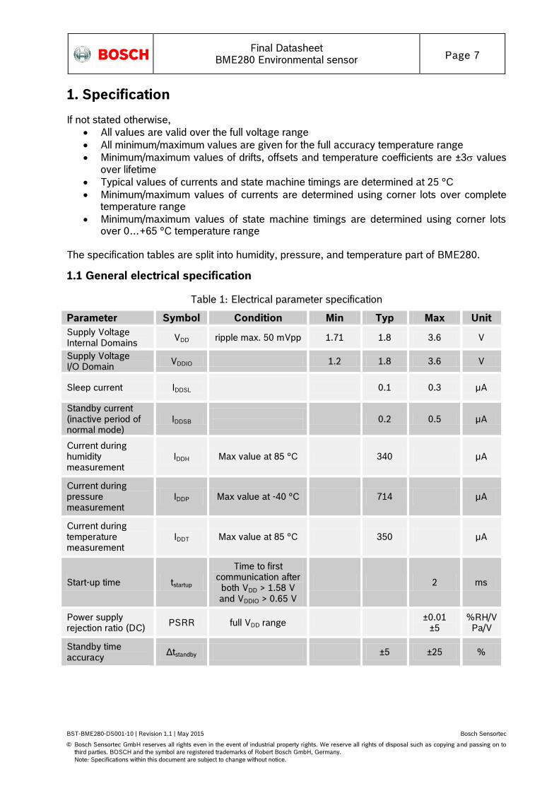
1.1 General electrical specification
Table 1: Electrical parameter specification
Parameter Symbol Condition Min Typ Max Unit
Supply Voltage Internal Domains
VDD ripple max. 50 mVpp 1.71 1.8 3.6 V
Supply Voltage I/O Domain
VDDIO 1.2 1.8 3.6 V
Sleep current IDDSL
0.1 0.3 µA
Standby current (inactive period of normal mode)
IDDSB
0.2 0.5 µA
Current during humidity measurement
IDDH Max value at 85 °C 340 µA
Current during pressure measurement
IDDP Max value at -40 °C 714 µA
Current during temperature measurement
IDDT Max value at 85 °C 350 µA
Start-up time tstartup
Time to first communication after
both VDD > 1.58 V and VDDIO > 0.65 V
2 ms
Power supply rejection ratio (DC)
PSRR full VDD range ±0.01
±5 %RH/V Pa/V
Standby time accuracy
Δtstandby ±5 ±25 %
Final Datasheet
BME280 Environmental sensor Page 8
BST-BME280-DS001-10 | Revision 1.1 | May 2015 Bosch Sensortec
© Bosch Sensortec GmbH reserves all rights even in the event of industrial property rights. We reserve all rights of disposal such as copying and passing on to
third parties. BOSCH and the symbol are registered trademarks of Robert Bosch GmbH, Germany.
Note: Specifications within this document are subject to change without notice.
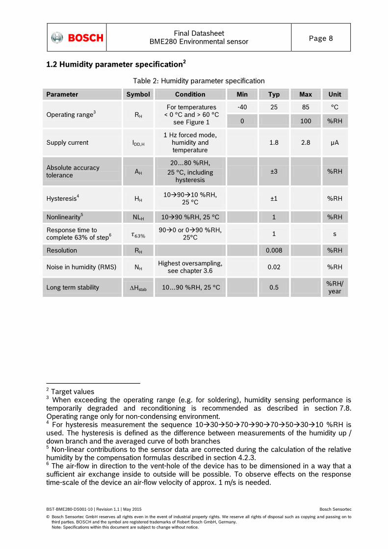
1.2 Humidity parameter specification2
Table 2: Humidity parameter specification
Parameter Symbol Condition Min Typ Max Unit
Operating range3 RH
For temperatures < 0 °C and > 60 °C
see Figure 1
-40 25 85 °C
0 100 %RH
Supply current IDD,H
1 Hz forced mode, humidity and temperature
1.8 2.8 µA
Absolute accuracy tolerance
AH
20…80 %RH,
25 °C, including hysteresis
1.3 ±3 1.4 %RH
Hysteresis4 HH
109010 %RH, 25 °C
1.5 ±1 %RH
Nonlinearity5 NLH 1090 %RH, 25 °C 1 %RH
Response time to complete 63% of step
6
900 or 090 %RH,
25°C 1 s
Resolution RH 0.008 %RH
Noise in humidity (RMS) NH Highest oversampling,
see chapter 3.6 0.02 %RH
Long term stability Hstab 10…90 %RH, 25 °C 0.5 %RH/year
2 Target values 3 When exceeding the operating range (e.g. for soldering), humidity sensing performance is temporarily degraded and reconditioning is recommended as described in section 7.8. Operating range only for non-condensing environment. 4 For hysteresis measurement the sequence 103050709070503010 %RH is used. The hysteresis is defined as the difference between measurements of the humidity up / down branch and the averaged curve of both branches 5 Non-linear contributions to the sensor data are corrected during the calculation of the relative humidity by the compensation formulas described in section 4.2.3. 6 The air-flow in direction to the vent-hole of the device has to be dimensioned in a way that a sufficient air exchange inside to outside will be possible. To observe effects on the response time-scale of the device an air-flow velocity of approx. 1 m/s is needed.
Final Datasheet
BME280 Environmental sensor Page 9
BST-BME280-DS001-10 | Revision 1.1 | May 2015 Bosch Sensortec
© Bosch Sensortec GmbH reserves all rights even in the event of industrial property rights. We reserve all rights of disposal such as copying and passing on to
third parties. BOSCH and the symbol are registered trademarks of Robert Bosch GmbH, Germany.
Note: Specifications within this document are subject to change without notice.
100
80
60
20
0
40
Re
lative
hu
mid
ity [%
]
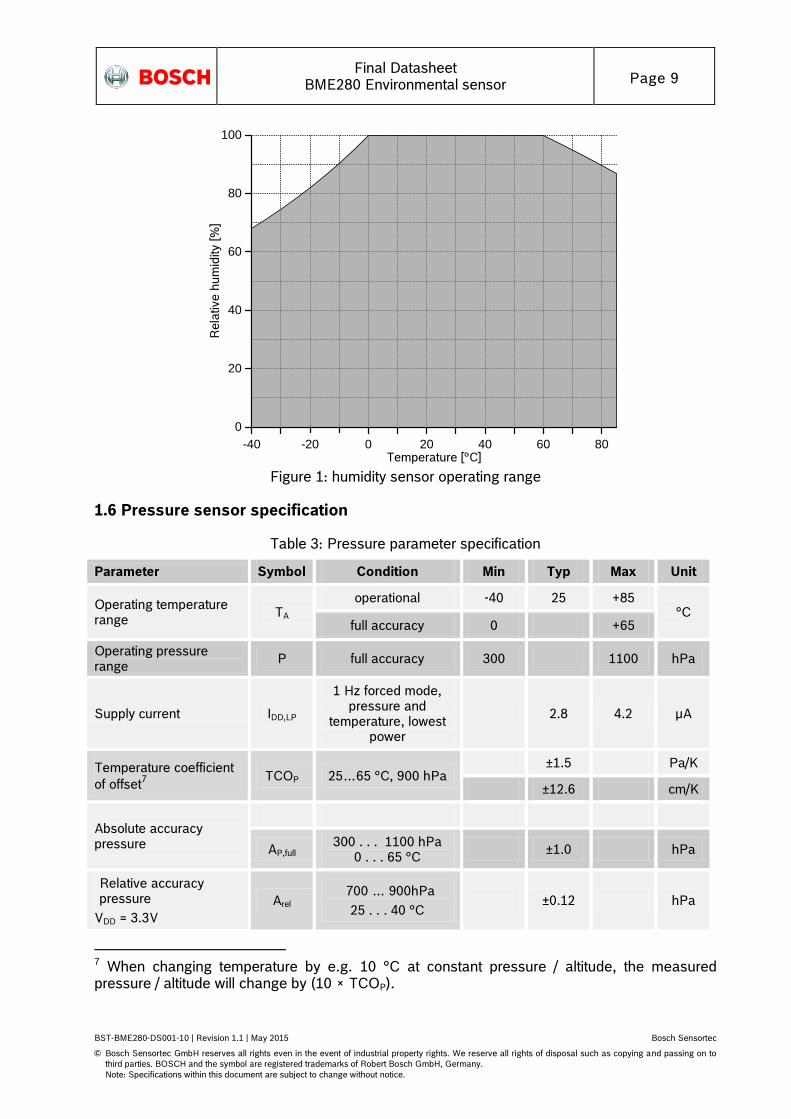
Temperature [°C]-40 -20 0 20 40 60 80
Figure 1: humidity sensor operating range
1.6 Pressure sensor specification
Table 3: Pressure parameter specification
Parameter Symbol Condition Min Typ Max Unit
Operating temperature range
TA
operational -40 25 +85 °C
full accuracy 0 +65
Operating pressure range
P full accuracy 300 1100 hPa
Supply current IDD,LP
1 Hz forced mode, pressure and
temperature, lowest power
2.8 4.2 µA
Temperature coefficient
of offset7
TCOP 25…65 °C, 900 hPa ±1.5 Pa/K
±12.6 cm/K
Absolute accuracy pressure
AP,full 300 . . . 1100 hPa
0 . . . 65 °C ±1.0 hPa
Relative accuracy pressure
VDD = 3.3V
Arel 700 … 900hPa
25 . . . 40 °C ±0.12 hPa
7 When changing temperature by e.g. 10 °C at constant pressure / altitude, the measured pressure / altitude will change by (10 × TCOP).

Final Datasheet
BME280 Environmental sensor Page 10
BST-BME280-DS001-10 | Revision 1.1 | May 2015 Bosch Sensortec
© Bosch Sensortec GmbH reserves all rights even in the event of industrial property rights. We reserve all rights of disposal such as copying and passing on to
third parties. BOSCH and the symbol are registered trademarks of Robert Bosch GmbH, Germany.
Note: Specifications within this document are subject to change without notice.
Resolution of pressure output data
RP Highest oversampling 0.18 Pa
Noise in pressure
NP,fullBW Full bandwidth,
highest oversampling See chapter 3.6
1.3 Pa
11 cm
NP,filtered Reduced bandwidth, highest oversampling
See chapter 3.6
0.2 Pa
1.7 cm
Solder drift Minimum solder height
50µm -0.5 +2.0 hPa
Long term stability8 Pstab per year ±1.0 hPa
Possible sampling rate fsample_PLowest oversampling,
see chapter 9.2 157 182 Hz
1.7 Temperature sensor specification
Table 4: Pressure parameter specification
Parameter Symbol Condition Min Typ Max Unit
Operating range T Operational -40 25 85 °C
Full accuracy 0 65 °C
Supply current IDD,T 1 Hz forced mode,
temperature measurement only
1.0 µA
Absolute accuracy temperature
9
AT,25 25 °C ±0.5 °C
AT,full 0…65 °C ±1.0 °C
Output resolution RT API output resolution 0.01 °C
RMS noise NT Lowest oversampling 0.005 °C
2. Absolute maximum ratings
The absolute maximum ratings are determined over complete temperature range using corner lots. The values are provided in Table 5.
8 Long term stability is specified in the full accuracy operating pressure range 0 … 65 °C 9 Temperature measured by the internal temperature sensor. This temperature value depends on the PCB temperature, sensor element self-heating and ambient temperature and is typically above ambient temperature.
Final Datasheet
BME280 Environmental sensor Page 11
BST-BME280-DS001-10 | Revision 1.1 | May 2015 Bosch Sensortec
© Bosch Sensortec GmbH reserves all rights even in the event of industrial property rights. We reserve all rights of disposal such as copying and passing on to
third parties. BOSCH and the symbol are registered trademarks of Robert Bosch GmbH, Germany.
Note: Specifications within this document are subject to change without notice.
Table 5: Absolute maximum ratings
Parameter Condition Min Max Unit
Voltage at any supply pin VDD and VDDIO pin -0.3 4.25 V
Voltage at any interface pin -0.3 VDDIO + 0.3 V
Storage temperature ≤ 65% RH -45 +85 °C
Pressure 0 20 000 hPa
ESD
HBM, at any pin ±2 kV
CDM ±500 V
Machine model ±200 V
Condensation No power supplied Allowed
3. Functional description
3.1 Block diagram
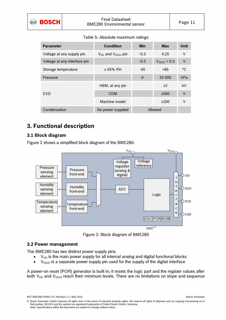
Figure 2 shows a simplified block diagram of the BME280:
Logic
Pressure
front-end
OSC NVM
Voltage
referenceVoltage
regulator
(analog &
digital)
VDDIO
GND
I
n
t
e
r
f
a
c
e
SDI
SDO
SCK
CSB
VDD
POR
Pressure
sensing
element
Humidity
sensing
element
Humidity
front-end
Temperature
front-end
Temperature
sensing
element
ADC
Figure 2: Block diagram of BME280
3.2 Power management
The BME280 has two distinct power supply pins
VDD is the main power supply for all internal analog and digital functional blocks
VDDIO is a separate power supply pin used for the supply of the digital interface A power-on reset (POR) generator is built in; it resets the logic part and the register values after both VDD and VDDIO reach their minimum levels. There are no limitations on slope and sequence
Final Datasheet
BME280 Environmental sensor Page 12
BST-BME280-DS001-10 | Revision 1.1 | May 2015 Bosch Sensortec
© Bosch Sensortec GmbH reserves all rights even in the event of industrial property rights. We reserve all rights of disposal such as copying and passing on to
third parties. BOSCH and the symbol are registered trademarks of Robert Bosch GmbH, Germany.
Note: Specifications within this document are subject to change without notice.
of raising the VDD and VDDIO levels. After powering up, the sensor settles in sleep mode (described in chapter 3.3.2). It is prohibited to keep any interface pin (SDI, SDO, SCK or CSB) at a logical high level when VDDIO is switched off. Such a configuration can permanently damage the device due an excessive current flow through the ESD protection diodes. If VDDIO is supplied, but VDD is not, the interface pins are kept at a high-Z level. The bus can therefore already be used freely before the BME280 VDD supply is established. Resetting the sensor is possible by cycling VDD level or by writing a soft reset command. Cycling the VDDIO level will not cause a reset.
3.3 Sensor modes
The BME280 offers three sensor modes: sleep mode, forced mode and normal mode. These can be selected using the mode[1:0] setting (see chapter 5.4.5). The available modes are:
Sleep mode: no operation, all registers accessible, lowest power, selected after startup
Forced mode: perform one measurement, store results and return to sleep mode
Normal mode: perpetual cycling of measurements and inactive periods. The modes will be explained in detail in chapters 3.3.2 (sleep mode), 3.3.3 (forced mode) and 3.3.4 (normal mode).
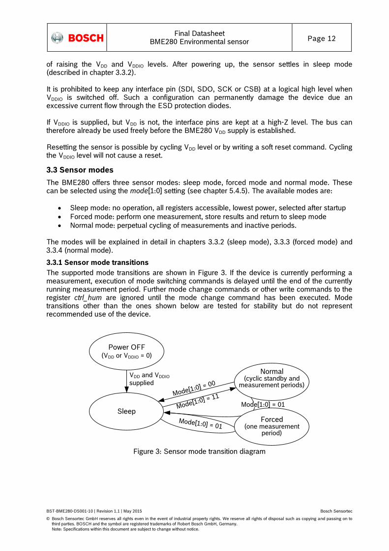
3.3.1 Sensor mode transitions
The supported mode transitions are shown in Figure 3. If the device is currently performing a measurement, execution of mode switching commands is delayed until the end of the currently running measurement period. Further mode change commands or other write commands to the register ctrl_hum are ignored until the mode change command has been executed. Mode transitions other than the ones shown below are tested for stability but do not represent recommended use of the device.
Power OFF(VDD or VDDIO = 0)
VDD and VDDIO
supplied
Mode[1:0] = 00
Mode[1:0] = 01
Sleep
Normal(cyclic standby and
measurement periods)
Mode[1:0] = 11
Forced(one measurement
period)
Mode[1:0] = 01
Figure 3: Sensor mode transition diagram
Final Datasheet
BME280 Environmental sensor Page 13
BST-BME280-DS001-10 | Revision 1.1 | May 2015 Bosch Sensortec
© Bosch Sensortec GmbH reserves all rights even in the event of industrial property rights. We reserve all rights of disposal such as copying and passing on to
third parties. BOSCH and the symbol are registered trademarks of Robert Bosch GmbH, Germany.
Note: Specifications within this document are subject to change without notice.
3.3.2 Sleep mode
Sleep mode is entered by default after power on reset. In sleep mode, no measurements are performed and power consumption (IDDSM) is at a minimum. All registers are accessible; Chip-ID and compensation coefficients can be read. There are no special restrictions on interface timings.
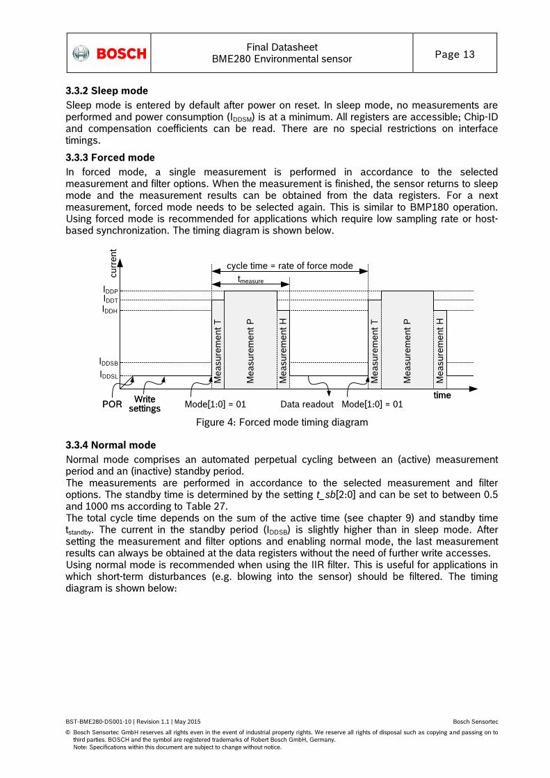
3.3.3 Forced mode
In forced mode, a single measurement is performed in accordance to the selected measurement and filter options. When the measurement is finished, the sensor returns to sleep mode and the measurement results can be obtained from the data registers. For a next measurement, forced mode needs to be selected again. This is similar to BMP180 operation. Using forced mode is recommended for applications which require low sampling rate or host-based synchronization. The timing diagram is shown below.
timePOR Data readout
Writesettings Mode[1:0] = 01
M
ea
su
rem
en
t H
time
cu
rre
nt
IDDSL
IDDSB
IDDP
IDDH
POR
M
ea
su
rem
en
t T
M
ea
su
rem
en
t P
Writesettings
IDDT
M
ea
su
rem
en
t H
M
ea
su
rem
en
t T
M
ea
su
rem
en
t P
tmeasure
Mode[1:0] = 01
cycle time = rate of force mode
Figure 4: Forced mode timing diagram
3.3.4 Normal mode
Normal mode comprises an automated perpetual cycling between an (active) measurement period and an (inactive) standby period. The measurements are performed in accordance to the selected measurement and filter options. The standby time is determined by the setting t_sb[2:0] and can be set to between 0.5 and 1000 ms according to Table 27. The total cycle time depends on the sum of the active time (see chapter 9) and standby time tstandby. The current in the standby period (IDDSB) is slightly higher than in sleep mode. After setting the measurement and filter options and enabling normal mode, the last measurement results can always be obtained at the data registers without the need of further write accesses. Using normal mode is recommended when using the IIR filter. This is useful for applications in which short-term disturbances (e.g. blowing into the sensor) should be filtered. The timing diagram is shown below:
Final Datasheet
BME280 Environmental sensor Page 14
BST-BME280-DS001-10 | Revision 1.1 | May 2015 Bosch Sensortec
© Bosch Sensortec GmbH reserves all rights even in the event of industrial property rights. We reserve all rights of disposal such as copying and passing on to
third parties. BOSCH and the symbol are registered trademarks of Robert Bosch GmbH, Germany.
Note: Specifications within this document are subject to change without notice.
M
ea
su
rem
en
t H
time
cu
rre
nt
IDDSL
IDDSB
IDDP
IDDH
POR Mode[1:0] = 11 M
ea
su
rem
en
t P
M
ea
su
rem
en
t T
Data readout
when needed
Writesettings
tstandby
IDDT
M
ea
su
rem
en
t H
M
ea
su
rem
en
t P
M
ea
su
rem
en
t T
tmeasure
cycle time = tmeasure + tstandby
Figure 5: Normal mode timing diagram
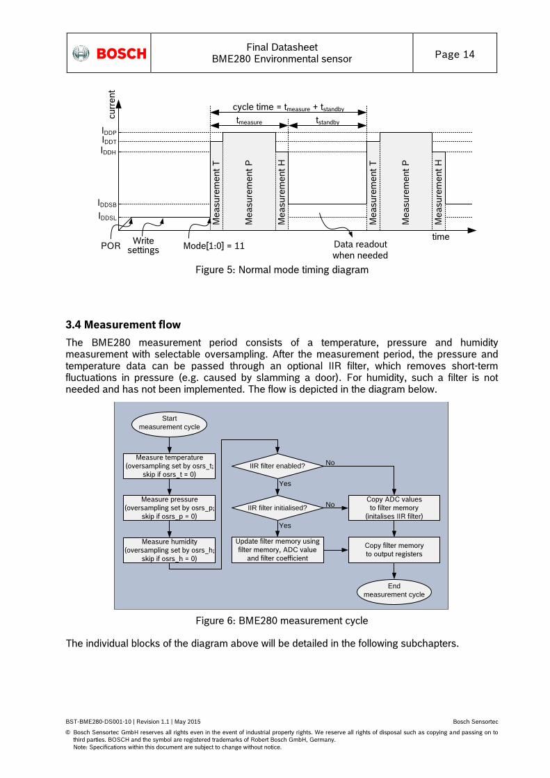
3.4 Measurement flow
The BME280 measurement period consists of a temperature, pressure and humidity measurement with selectable oversampling. After the measurement period, the pressure and temperature data can be passed through an optional IIR filter, which removes short-term fluctuations in pressure (e.g. caused by slamming a door). For humidity, such a filter is not needed and has not been implemented. The flow is depicted in the diagram below.
Measure temperature
(oversampling set by osrs_t;
skip if osrs_t = 0)
Start
measurement cycle
Measure pressure
(oversampling set by osrs_p;
skip if osrs_p = 0)
IIR filter enabled?
End
measurement cycle
IIR filter initialised?
Copy ADC values
to filter memory
(initalises IIR filter)
No
Update filter memory using
filter memory, ADC value
and filter coefficient
No
Yes
Yes
Copy filter memory
to output registers
Measure humidity
(oversampling set by osrs_h;
skip if osrs_h = 0)
Figure 6: BME280 measurement cycle
The individual blocks of the diagram above will be detailed in the following subchapters.
Final Datasheet
BME280 Environmental sensor Page 15
BST-BME280-DS001-10 | Revision 1.1 | May 2015 Bosch Sensortec
© Bosch Sensortec GmbH reserves all rights even in the event of industrial property rights. We reserve all rights of disposal such as copying and passing on to
third parties. BOSCH and the symbol are registered trademarks of Robert Bosch GmbH, Germany.
Note: Specifications within this document are subject to change without notice.
3.4.1 Humidity measurement
The humidity measurement can be enabled or skipped. When enabled, several oversampling options exist. The humidity measurement is controlled by the osrs_h[2:0] setting, which is detailed in chapter 5.4.3. For the humidity measurement, oversampling is possible to reduce the noise. The resolution of the humidity measurement is fixed at 16 bit ADC output.
3.4.2 Pressure measurement
Pressure measurement can be enabled or skipped. When enabled, several oversampling options exist. The pressure measurement is controlled by the osrs_p[2:0] setting which is detailed in chapter 5.4.5. For the pressure measurement, oversampling is possible to reduce the noise. The resolution of the pressure data depends on the IIR filter (see chapter 3.4.4) and the oversampling setting (see chapter 5.4.5):
When the IIR filter is enabled, the pressure resolution is 20 bit.
When the IIR filter is disabled, the pressure resolution is 16 + (osrs_p – 1) bit, e.g. 18 bit when osrs_p is set to ‘3’.
3.4.3 Temperature measurement
Temperature measurement can be enabled or skipped. Skipping the measurement could be useful to measure pressure extremely rapidly. When enabled, several oversampling options exist. The temperature measurement is controlled by the osrs_t[2:0] setting which is detailed in chapter 5.4.5. For the temperature measurement, oversampling is possible to reduce the noise. The resolution of the temperature data depends on the IIR filter (see chapter 3.4.4) and the oversampling setting (see chapter 5.4.5):
When the IIR filter is enabled, the temperature resolution is 20 bit.
When the IIR filter is disabled, the temperature resolution is 16 + (osrs_t – 1) bit, e.g. 18 bit when osrs_t is set to ‘3’.
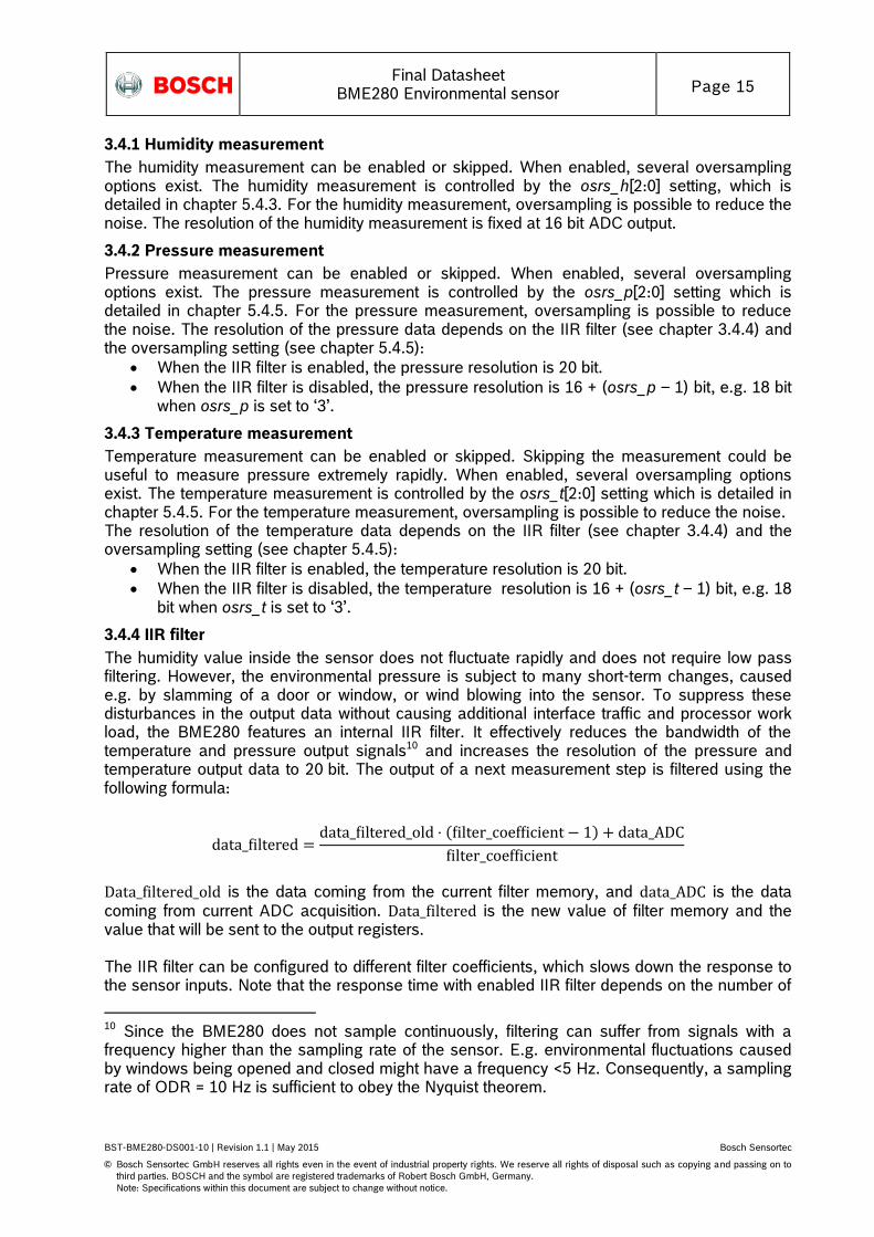
3.4.4 IIR filter
The humidity value inside the sensor does not fluctuate rapidly and does not require low pass filtering. However, the environmental pressure is subject to many short-term changes, caused e.g. by slamming of a door or window, or wind blowing into the sensor. To suppress these disturbances in the output data without causing additional interface traffic and processor work load, the BME280 features an internal IIR filter. It effectively reduces the bandwidth of the temperature and pressure output signals10 and increases the resolution of the pressure and temperature output data to 20 bit. The output of a next measurement step is filtered using the following formula:
Data_filtered_old is the data coming from the current filter memory, and data_ADC is the data
coming from current ADC acquisition. Data_filtered is the new value of filter memory and the value that will be sent to the output registers. The IIR filter can be configured to different filter coefficients, which slows down the response to the sensor inputs. Note that the response time with enabled IIR filter depends on the number of
10 Since the BME280 does not sample continuously, filtering can suffer from signals with a frequency higher than the sampling rate of the sensor. E.g. environmental fluctuations caused by windows being opened and closed might have a frequency <5 Hz. Consequently, a sampling rate of ODR = 10 Hz is sufficient to obey the Nyquist theorem.
Final Datasheet
BME280 Environmental sensor Page 16
BST-BME280-DS001-10 | Revision 1.1 | May 2015 Bosch Sensortec
© Bosch Sensortec GmbH reserves all rights even in the event of industrial property rights. We reserve all rights of disposal such as copying and passing on to
third parties. BOSCH and the symbol are registered trademarks of Robert Bosch GmbH, Germany.
Note: Specifications within this document are subject to change without notice.
samples generated, which means that the data output rate must be known to calculate the actual response time. For register configuration, please refer to Table 28. A sample response time calculation is shown in chapter 9.4.
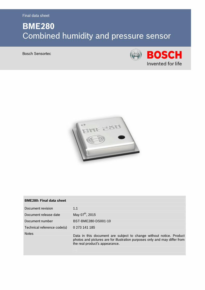
Table 6: filter settings
Filter coefficient Samples to reach ≥75 %
of step response
Filter off 1
2 2
4 5
8 11
16 22
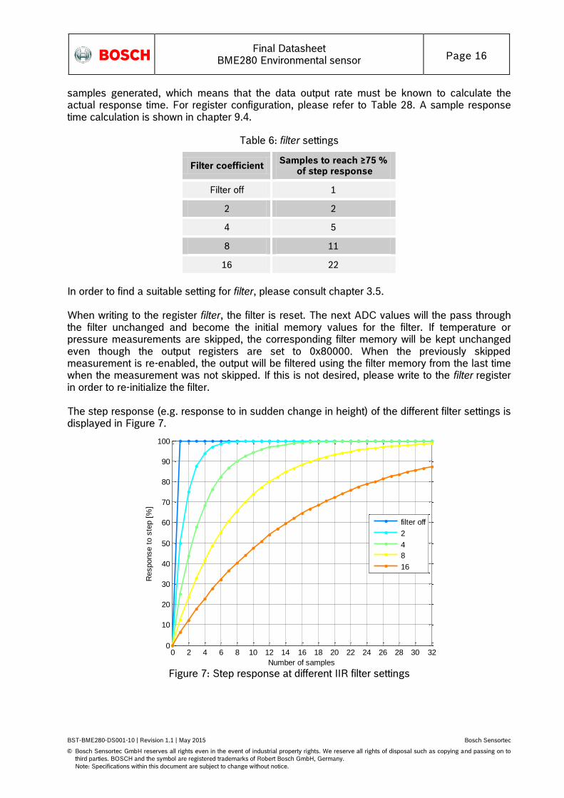
In order to find a suitable setting for filter, please consult chapter 3.5. When writing to the register filter, the filter is reset. The next ADC values will the pass through the filter unchanged and become the initial memory values for the filter. If temperature or pressure measurements are skipped, the corresponding filter memory will be kept unchanged even though the output registers are set to 0x80000. When the previously skipped measurement is re-enabled, the output will be filtered using the filter memory from the last time when the measurement was not skipped. If this is not desired, please write to the filter register in order to re-initialize the filter. The step response (e.g. response to in sudden change in height) of the different filter settings is displayed in Figure 7.
Figure 7: Step response at different IIR filter settings
0 2 4 6 8 10 12 14 16 18 20 22 24 26 28 30 320
10
20
30
40
50
60
70
80
90
100
Number of samples
Response t
o s
tep [
%]
Step response at different IIR filter settings
filter off
2
4
8
16
Final Datasheet
BME280 Environmental sensor Page 17
BST-BME280-DS001-10 | Revision 1.1 | May 2015 Bosch Sensortec
© Bosch Sensortec GmbH reserves all rights even in the event of industrial property rights. We reserve all rights of disposal such as copying and passing on to
third parties. BOSCH and the symbol are registered trademarks of Robert Bosch GmbH, Germany.
Note: Specifications within this document are subject to change without notice.
3.5 Recommended modes of operation
The different oversampling options, filter settings and sensor modes result in a large number of possible settings. In this chapter, a number of settings recommended for various scenarios are presented.
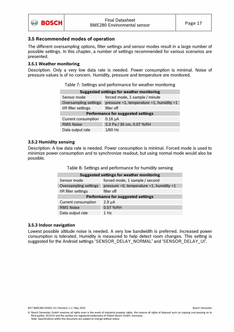
3.5.1 Weather monitoring
Description: Only a very low data rate is needed. Power consumption is minimal. Noise of pressure values is of no concern. Humidity, pressure and temperature are monitored.
Table 7: Settings and performance for weather monitoring
Suggested settings for weather monitoring
Sensor mode forced mode, 1 sample / minute
Oversampling settings pressure ×1, temperature ×1, humidity ×1
IIR filter settings filter off
Performance for suggested settings
Current consumption 0.16 µA
RMS Noise 3.3 Pa / 30 cm, 0.07 %RH
Data output rate 1/60 Hz
3.5.2 Humidity sensing
Description: A low data rate is needed. Power consumption is minimal. Forced mode is used to minimize power consumption and to synchronize readout, but using normal mode would also be possible.
Table 8: Settings and performance for humidity sensing
Suggested settings for weather monitoring
Sensor mode forced mode, 1 sample / second
Oversampling settings pressure ×0, temperature ×1, humidity ×1
IIR filter settings filter off
Performance for suggested settings
Current consumption 2.9 µA
RMS Noise 0.07 %RH
Data output rate 1 Hz
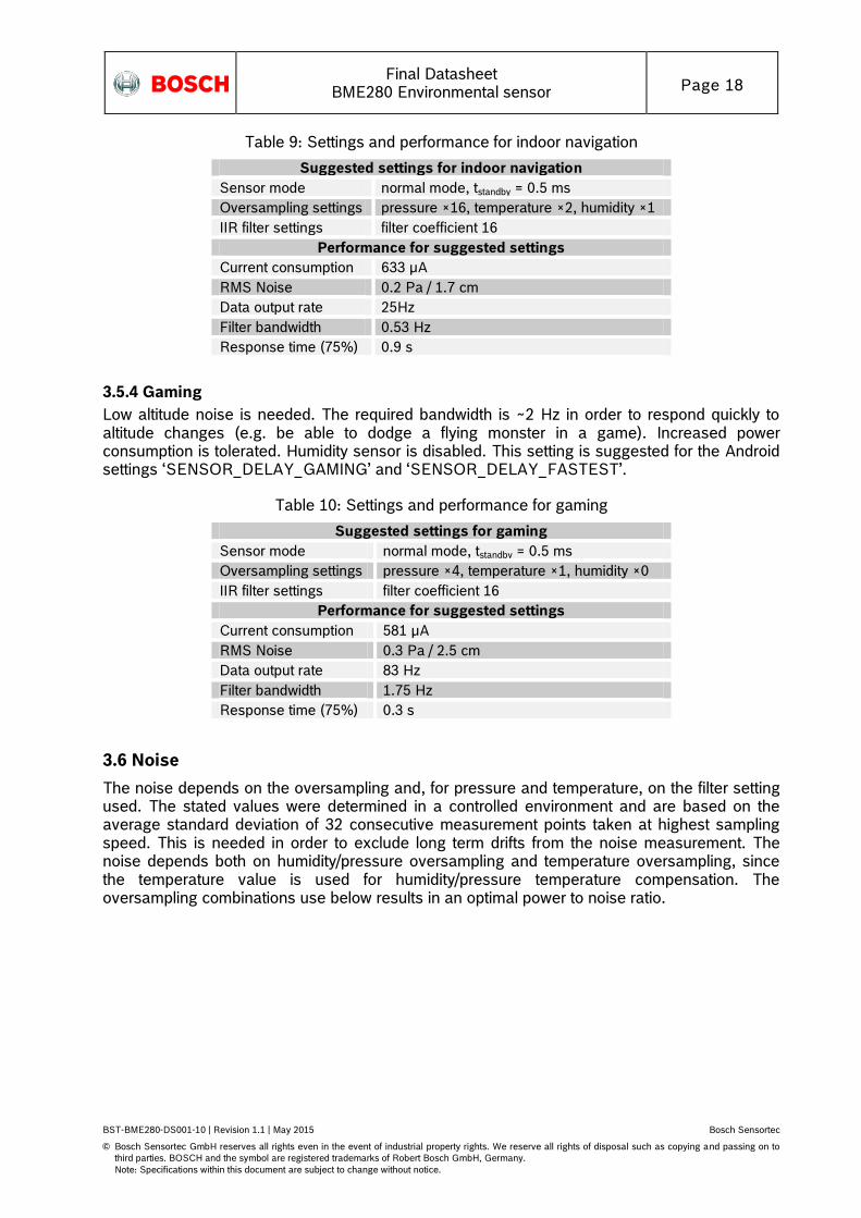
3.5.3 Indoor navigation
Lowest possible altitude noise is needed. A very low bandwidth is preferred. Increased power consumption is tolerated. Humidity is measured to help detect room changes. This setting is suggested for the Android settings ‘SENSOR_DELAY_NORMAL’ and ‘SENSOR_DELAY_UI’.
Final Datasheet
BME280 Environmental sensor Page 18
BST-BME280-DS001-10 | Revision 1.1 | May 2015 Bosch Sensortec
© Bosch Sensortec GmbH reserves all rights even in the event of industrial property rights. We reserve all rights of disposal such as copying and passing on to
third parties. BOSCH and the symbol are registered trademarks of Robert Bosch GmbH, Germany.
Note: Specifications within this document are subject to change without notice.
Table 9: Settings and performance for indoor navigation
Suggested settings for indoor navigation
Sensor mode normal mode, tstandby = 0.5 ms
Oversampling settings pressure ×16, temperature ×2, humidity ×1
IIR filter settings filter coefficient 16
Performance for suggested settings
Current consumption 633 µA
RMS Noise 0.2 Pa / 1.7 cm
Data output rate 25Hz
Filter bandwidth 0.53 Hz
Response time (75%) 0.9 s
3.5.4 Gaming
Low altitude noise is needed. The required bandwidth is ~2 Hz in order to respond quickly to altitude changes (e.g. be able to dodge a flying monster in a game). Increased power consumption is tolerated. Humidity sensor is disabled. This setting is suggested for the Android settings ‘SENSOR_DELAY_GAMING’ and ‘SENSOR_DELAY_FASTEST’.
Table 10: Settings and performance for gaming
Suggested settings for gaming
Sensor mode normal mode, tstandby = 0.5 ms
Oversampling settings pressure ×4, temperature ×1, humidity ×0
IIR filter settings filter coefficient 16
Performance for suggested settings
Current consumption 581 µA
RMS Noise 0.3 Pa / 2.5 cm
Data output rate 83 Hz
Filter bandwidth 1.75 Hz
Response time (75%) 0.3 s
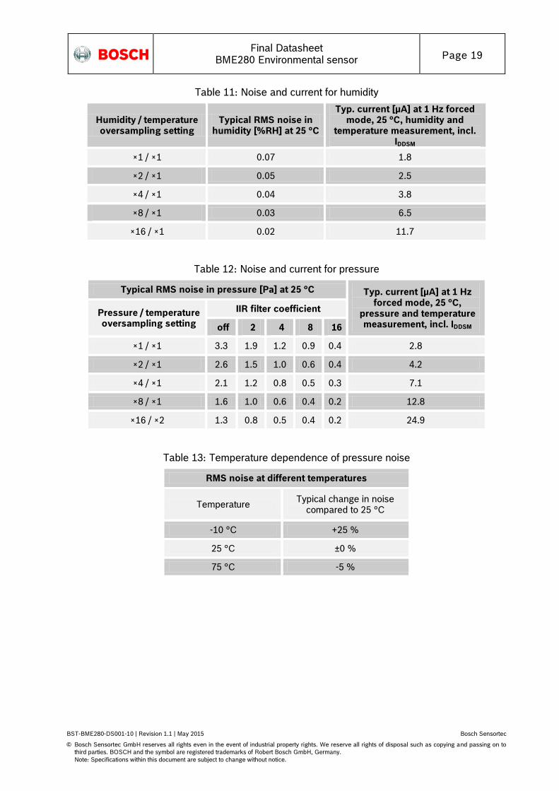
3.6 Noise
The noise depends on the oversampling and, for pressure and temperature, on the filter setting used. The stated values were determined in a controlled environment and are based on the average standard deviation of 32 consecutive measurement points taken at highest sampling speed. This is needed in order to exclude long term drifts from the noise measurement. The noise depends both on humidity/pressure oversampling and temperature oversampling, since the temperature value is used for humidity/pressure temperature compensation. The oversampling combinations use below results in an optimal power to noise ratio.
Final Datasheet
BME280 Environmental sensor Page 19
BST-BME280-DS001-10 | Revision 1.1 | May 2015 Bosch Sensortec
© Bosch Sensortec GmbH reserves all rights even in the event of industrial property rights. We reserve all rights of disposal such as copying and passing on to
third parties. BOSCH and the symbol are registered trademarks of Robert Bosch GmbH, Germany.
Note: Specifications within this document are subject to change without notice.
Table 11: Noise and current for humidity
Humidity / temperature oversampling setting
Typical RMS noise in humidity [%RH] at 25 °C
Typ. current [µA] at 1 Hz forced mode, 25 °C, humidity and
temperature measurement, incl. IDDSM
×1 / ×1 0.07 1.8
×2 / ×1 0.05 2.5
×4 / ×1 0.04 3.8
×8 / ×1 0.03 6.5
×16 / ×1 0.02 11.7
Table 12: Noise and current for pressure
Typical RMS noise in pressure [Pa] at 25 °C Typ. current [µA] at 1 Hz forced mode, 25 °C,
pressure and temperature measurement, incl. IDDSM
Pressure / temperature oversampling setting
IIR filter coefficient
off 2 4 8 16
×1 / ×1 3.3 1.9 1.2 0.9 0.4 2.8
×2 / ×1 2.6 1.5 1.0 0.6 0.4 4.2
×4 / ×1 2.1 1.2 0.8 0.5 0.3 7.1
×8 / ×1 1.6 1.0 0.6 0.4 0.2 12.8
×16 / ×2 1.3 0.8 0.5 0.4 0.2 24.9
Table 13: Temperature dependence of pressure noise
RMS noise at different temperatures
Temperature Typical change in noise
compared to 25 °C
-10 °C +25 %
25 °C ±0 %
75 °C -5 %
Final Datasheet
BME280 Environmental sensor Page 20
BST-BME280-DS001-10 | Revision 1.1 | May 2015 Bosch Sensortec
© Bosch Sensortec GmbH reserves all rights even in the event of industrial property rights. We reserve all rights of disposal such as copying and passing on to
third parties. BOSCH and the symbol are registered trademarks of Robert Bosch GmbH, Germany.
Note: Specifications within this document are subject to change without notice.
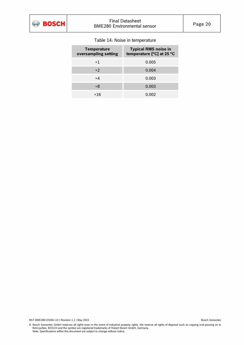
Table 14: Noise in temperature
Temperature oversampling setting
Typical RMS noise in temperature [°C] at 25 °C
×1 0.005
×2 0.004
×4 0.003
×8 0.003
×16 0.002

Final Datasheet
BME280 Environmental sensor Page 21
BST-BME280-DS001-10 | Revision 1.1 | May 2015 Bosch Sensortec
© Bosch Sensortec GmbH reserves all rights even in the event of industrial property rights. We reserve all rights of disposal such as copying and passing on to
third parties. BOSCH and the symbol are registered trademarks of Robert Bosch GmbH, Germany.
Note: Specifications within this document are subject to change without notice.
4. Data readout
To read out data after a conversion, it is strongly recommended to use a burst read and not address every register individually. This will prevent a possible mix-up of bytes belonging to different measurements and reduce interface traffic. Note that in I²C mode, even when pressure was not measured, reading the unused registers is faster than reading temperature and humidity data separately. Data readout is done by starting a burst read from 0xF7 to 0xFC (temperature and pressure) or from 0xF7 to 0xFE (temperature, pressure and humidity). The data are read out in an unsigned 20-bit format both for pressure and for temperature and in an unsigned 16-bit format for humidity. It is strongly recommended to use the BME280 API, available from Bosch Sensortec, for readout and compensation. For details on memory map and interfaces, please consult chapters 5 and 6 respectively. After the uncompensated values for pressure, temperature and humidity ‘ut’, ‘up’ and ‘uh’ have been read, the actual humidity, pressure and temperature needs to be calculated using the compensation parameters stored in the device. The procedure is elaborated in chapter 4.2.
4.1 Data register shadowing
In normal mode, the timing of measurements is not necessarily synchronized to the readout by the user. This means that new measurement results may become available while the user is reading the results from the previous measurement. In this case, shadowing is performed in order to guarantee data consistency. Shadowing will only work if all data registers are read in a single burst read. Therefore, the user must use burst reads if he does not synchronize data readout with the measurement cycle. Using several independent read commands may result in inconsistent data. If a new measurement is finished and the data registers are still being read, the new measurement results are transferred into shadow data registers. The content of shadow registers is transferred into data registers as soon as the user ends the burst read, even if not all data registers were read. The end of the burst read is marked by the rising edge of CSB pin in SPI case or by the recognition of a stop condition in I2C case. After the end of the burst read, all user data registers are updated at once.
4.2 Output compensation
The BME280 output consists of the ADC output values. However, each sensing element behaves differently. Therefore, the actual pressure and temperature must be calculated using a set of calibration parameters. In this chapter, the method to read out the trimming values will be given. The recommended calculation uses fixed point arithmetic and is given in chapter 4.2.3. In high-level languages like Matlab™ or LabVIEW™, fixed-point code may not be well supported. In this case the floating-point code in appendix 8.1 can be used as an alternative. For 8-bit micro controllers, the variable size may be limited. In this case a simplified 32 bit integer code with reduced accuracy is given in appendix 8.2.
4.2.1 Computational requirements
In the table below an overview is given for the number of clock cycles needed for compensation on a 32 bit Cortex-M3 micro controller with GCC optimization level -O2. This controller does not feature a floating point unit, thus all floating-point calculations are emulated. Floating point is only recommended for PC application, where an FPU is present and these calculations are performed drastically faster.

Final Datasheet
BME280 Environmental sensor Page 22
BST-BME280-DS001-10 | Revision 1.1 | May 2015 Bosch Sensortec
© Bosch Sensortec GmbH reserves all rights even in the event of industrial property rights. We reserve all rights of disposal such as copying and passing on to
third parties. BOSCH and the symbol are registered trademarks of Robert Bosch GmbH, Germany.
Note: Specifications within this document are subject to change without notice.
Table 15: Computational requirements for compensation formulas
Compensation of
Number of clocks (ARM Cortex-M3)
32 bit integer
64 bit integer
Double precision
Humidity ~83 – ~2900 11
Temperature ~46 – ~2400 11
Pressure ~112 12
~1400 ~5400 11
4.2.2 Trimming parameter readout
The trimming parameters are programmed into the devices’ non-volatile memory (NVM) during production and cannot be altered by the customer. Each compensation word is a 16-bit signed or unsigned integer value stored in two’s complement. As the memory is organized into 8-bit words, two words must always be combined in order to represent the compensation word. The 8-bit registers are named calib00…calib41 and are stored at memory addresses 0x88…0xA1 and 0xE1…0xE7. The corresponding compensation words are named dig_T# for temperature compensation related values, dig_P# for pressure related values and dig_H# for humidity related values. The mapping is seen in Table 16.
Table 16: Compensation parameter storage, naming and data type
Register Address Register content Data type
0x88 / 0x89 dig_T1 [7:0] / [15:8] unsigned short
0x8A / 0x8B dig_T2 [7:0] / [15:8] signed short
0x8C / 0x8D dig_T3 [7:0] / [15:8] signed short
0x8E / 0x8F dig_P1 [7:0] / [15:8] unsigned short
0x90 / 0x91 dig_P2 [7:0] / [15:8] signed short
0x92 / 0x93 dig_P3 [7:0] / [15:8] signed short
0x94 / 0x95 dig_P4 [7:0] / [15:8] signed short
0x96 / 0x97 dig_P5 [7:0] / [15:8] signed short
0x98 / 0x99 dig_P6 [7:0] / [15:8] signed short
0x9A / 0x9B dig_P7 [7:0] / [15:8] signed short
0x9C / 0x9D dig_P8 [7:0] / [15:8] signed short
0x9E / 0x9F dig_P9 [7:0] / [15:8] signed short
0xA1 dig_H1 [7:0] unsigned char
0xE1 / 0xE2 dig_H2 [7:0] / [15:8] signed short
0xE3 dig_H3 [7:0] unsigned char
11 Use only recommended for high-level programming languages like Matlab™ or LabVIEW™ 12 Use only recommended for 8-bit micro controllers
Final Datasheet
BME280 Environmental sensor Page 23
BST-BME280-DS001-10 | Revision 1.1 | May 2015 Bosch Sensortec
© Bosch Sensortec GmbH reserves all rights even in the event of industrial property rights. We reserve all rights of disposal such as copying and passing on to
third parties. BOSCH and the symbol are registered trademarks of Robert Bosch GmbH, Germany.
Note: Specifications within this document are subject to change without notice.
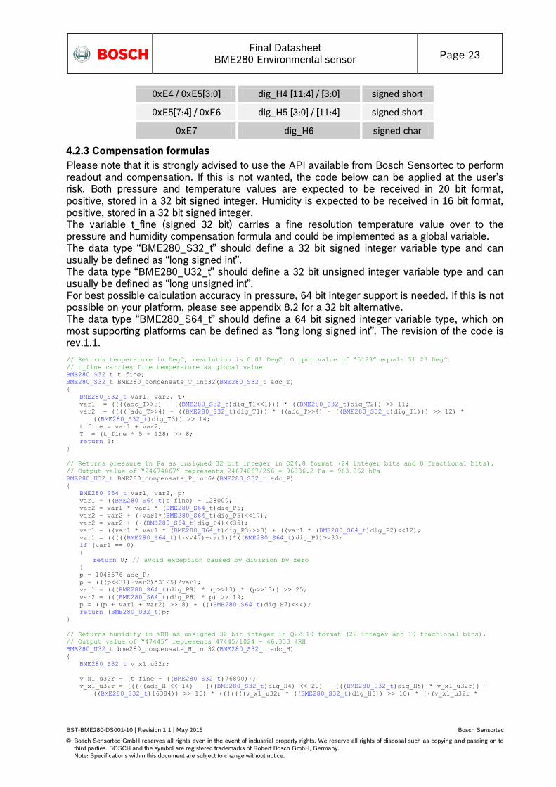
0xE4 / 0xE5[3:0] dig_H4 [11:4] / [3:0] signed short
0xE5[7:4] / 0xE6 dig_H5 [3:0] / [11:4] signed short
0xE7 dig_H6 signed char
4.2.3 Compensation formulas
Please note that it is strongly advised to use the API available from Bosch Sensortec to perform readout and compensation. If this is not wanted, the code below can be applied at the user’s risk. Both pressure and temperature values are expected to be received in 20 bit format, positive, stored in a 32 bit signed integer. Humidity is expected to be received in 16 bit format, positive, stored in a 32 bit signed integer. The variable t_fine (signed 32 bit) carries a fine resolution temperature value over to the pressure and humidity compensation formula and could be implemented as a global variable. The data type “BME280_S32_t” should define a 32 bit signed integer variable type and can usually be defined as “long signed int”. The data type “BME280_U32_t” should define a 32 bit unsigned integer variable type and can usually be defined as “long unsigned int”. For best possible calculation accuracy in pressure, 64 bit integer support is needed. If this is not possible on your platform, please see appendix 8.2 for a 32 bit alternative. The data type “BME280_S64_t” should define a 64 bit signed integer variable type, which on most supporting platforms can be defined as “long long signed int”. The revision of the code is rev.1.1.
// Returns temperature in DegC, resolution is 0.01 DegC. Output value of “5123” equals 51.23 DegC.
// t_fine carries fine temperature as global value
BME280_S32_t t_fine;
BME280_S32_t BME280_compensate_T_int32(BME280_S32_t adc_T)
BME280_S32_t var1, var2, T;
var1 = ((((adc_T>>3) – ((BME280_S32_t)dig_T1<<1))) * ((BME280_S32_t)dig_T2)) >> 11;
var2 = (((((adc_T>>4) – ((BME280_S32_t)dig_T1)) * ((adc_T>>4) – ((BME280_S32_t)dig_T1))) >> 12) *
((BME280_S32_t)dig_T3)) >> 14;
t_fine = var1 + var2;
T = (t_fine * 5 + 128) >> 8;
return T;
// Returns pressure in Pa as unsigned 32 bit integer in Q24.8 format (24 integer bits and 8 fractional bits).
// Output value of “24674867” represents 24674867/256 = 96386.2 Pa = 963.862 hPa
BME280_U32_t BME280_compensate_P_int64(BME280_S32_t adc_P)
BME280_S64_t var1, var2, p;
var1 = ((BME280_S64_t)t_fine) – 128000;
var2 = var1 * var1 * (BME280_S64_t)dig_P6;
var2 = var2 + ((var1*(BME280_S64_t)dig_P5)<<17);
var2 = var2 + (((BME280_S64_t)dig_P4)<<35);
var1 = ((var1 * var1 * (BME280_S64_t)dig_P3)>>8) + ((var1 * (BME280_S64_t)dig_P2)<<12);
var1 = (((((BME280_S64_t)1)<<47)+var1))*((BME280_S64_t)dig_P1)>>33;
if (var1 == 0)
return 0; // avoid exception caused by division by zero
p = 1048576-adc_P;
p = (((p<<31)-var2)*3125)/var1;
var1 = (((BME280_S64_t)dig_P9) * (p>>13) * (p>>13)) >> 25;
var2 = (((BME280_S64_t)dig_P8) * p) >> 19;
p = ((p + var1 + var2) >> 8) + (((BME280_S64_t)dig_P7)<<4);
return (BME280_U32_t)p;
// Returns humidity in %RH as unsigned 32 bit integer in Q22.10 format (22 integer and 10 fractional bits).
// Output value of “47445” represents 47445/1024 = 46.333 %RH
BME280_U32_t bme280_compensate_H_int32(BME280_S32_t adc_H)
BME280_S32_t v_x1_u32r;
v_x1_u32r = (t_fine – ((BME280_S32_t)76800));
v_x1_u32r = (((((adc_H << 14) – (((BME280_S32_t)dig_H4) << 20) – (((BME280_S32_t)dig_H5) * v_x1_u32r)) +
((BME280_S32_t)16384)) >> 15) * (((((((v_x1_u32r * ((BME280_S32_t)dig_H6)) >> 10) * (((v_x1_u32r *
Final Datasheet
BME280 Environmental sensor Page 24
BST-BME280-DS001-10 | Revision 1.1 | May 2015 Bosch Sensortec
© Bosch Sensortec GmbH reserves all rights even in the event of industrial property rights. We reserve all rights of disposal such as copying and passing on to
third parties. BOSCH and the symbol are registered trademarks of Robert Bosch GmbH, Germany.
Note: Specifications within this document are subject to change without notice.
((BME280_S32_t)dig_H3)) >> 11) + ((BME280_S32_t)32768))) >> 10) + ((BME280_S32_t)2097152)) *
((BME280_S32_t)dig_H2) + 8192) >> 14));
v_x1_u32r = (v_x1_u32r – (((((v_x1_u32r >> 15) * (v_x1_u32r >> 15)) >> 7) * ((BME280_S32_t)dig_H1)) >> 4));
v_x1_u32r = (v_x1_u32r < 0 ? 0 : v_x1_u32r);
v_x1_u32r = (v_x1_u32r > 419430400 ? 419430400 : v_x1_u32r);
return (BME280_U32_t)(v_x1_u32r>>12);
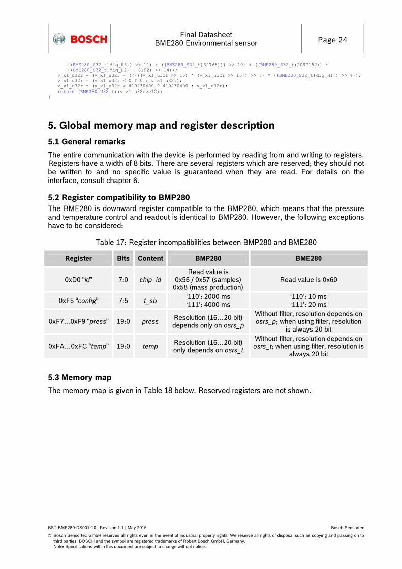
5. Global memory map and register description
5.1 General remarks
The entire communication with the device is performed by reading from and writing to registers. Registers have a width of 8 bits. There are several registers which are reserved; they should not be written to and no specific value is guaranteed when they are read. For details on the interface, consult chapter 6.
5.2 Register compatibility to BMP280
The BME280 is downward register compatible to the BMP280, which means that the pressure and temperature control and readout is identical to BMP280. However, the following exceptions have to be considered:
Table 17: Register incompatibilities between BMP280 and BME280
Register Bits Content BMP280 BME280
0xD0 “id” 7:0 chip_id Read value is
0x56 / 0x57 (samples) 0x58 (mass production)
Read value is 0x60
0xF5 “config” 7:5 t_sb ‘110’: 2000 ms ‘111’: 4000 ms
‘110’: 10 ms ‘111’: 20 ms
0xF7…0xF9 “press” 19:0 press Resolution (16…20 bit) depends only on osrs_p
Without filter, resolution depends on osrs_p; when using filter, resolution
is always 20 bit
0xFA…0xFC “temp” 19:0 temp Resolution (16…20 bit) only depends on osrs_t
Without filter, resolution depends on osrs_t; when using filter, resolution is
always 20 bit
5.3 Memory map
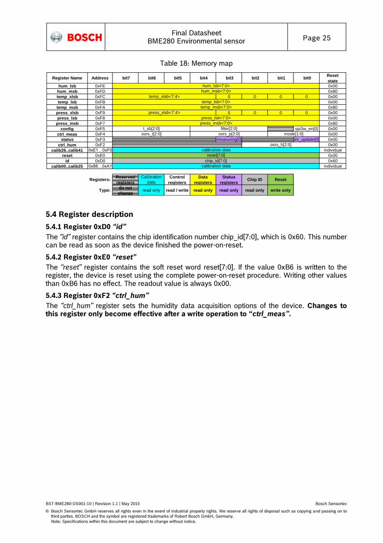
The memory map is given in Table 18 below. Reserved registers are not shown.
Final Datasheet
BME280 Environmental sensor Page 25
BST-BME280-DS001-10 | Revision 1.1 | May 2015 Bosch Sensortec
© Bosch Sensortec GmbH reserves all rights even in the event of industrial property rights. We reserve all rights of disposal such as copying and passing on to
third parties. BOSCH and the symbol are registered trademarks of Robert Bosch GmbH, Germany.
Note: Specifications within this document are subject to change without notice.
Table 18: Memory map
Register Name Address bit7 bit6 bit5 bit4 bit3 bit2 bit1 bit0Reset
statehum_lsb 0xFE 0x00
hum_msb 0xFD 0x80
temp_xlsb 0xFC 0 0 0 0 0x00
temp_lsb 0xFB 0x00
temp_msb 0xFA 0x80
press_xlsb 0xF9 0 0 0 0 0x00
press_lsb 0xF8 0x00
press_msb 0xF7 0x80
config 0xF5 spi3w_en[0] 0x00
ctrl_meas 0xF4 0x00
status 0xF3 measuring[0] im_update[0] 0x00
ctrl_hum 0xF2 0x00
calib26..calib41 0xE1…0xF0 individual
reset 0xE0 0x00
id 0xD0 0x60
calib00..calib25 0x88…0xA1 individual
Registers: Reserved
registers
Calibration
data
Control
registers
Data
registers
Status
registersChip ID Reset
Type: do not
changeread only read / write read only read only read only write only
hum_lsb<7:0>
press_lsb<7:0>
press_msb<7:0>
mode[1:0]
t_sb[2:0]
press_xlsb<7:4>
temp_xlsb<7:4>
temp_lsb<7:0>
temp_msb<7:0>
calibration data
chip_id[7:0]
osrs_h[2:0]
hum_msb<7:0>
calibration data
reset[7:0]
osrs_p[2:0]
filter[2:0]
osrs_t[2:0]
5.4 Register description
5.4.1 Register 0xD0 “id”
The “id” register contains the chip identification number chip_id[7:0], which is 0x60. This number can be read as soon as the device finished the power-on-reset.
5.4.2 Register 0xE0 “reset”
The “reset” register contains the soft reset word reset[7:0]. If the value 0xB6 is written to the register, the device is reset using the complete power-on-reset procedure. Writing other values than 0xB6 has no effect. The readout value is always 0x00.
5.4.3 Register 0xF2 “ctrl_hum”
The “ctrl_hum” register sets the humidity data acquisition options of the device. Changes to this register only become effective after a write operation to “ctrl_meas”.

Final Datasheet
BME280 Environmental sensor Page 26
BST-BME280-DS001-10 | Revision 1.1 | May 2015 Bosch Sensortec
© Bosch Sensortec GmbH reserves all rights even in the event of industrial property rights. We reserve all rights of disposal such as copying and passing on to
third parties. BOSCH and the symbol are registered trademarks of Robert Bosch GmbH, Germany.
Note: Specifications within this document are subject to change without notice.
Table 19: Register 0xF2 “ctrl_hum”
Register 0xF2 “ctrl_hum”
Name Description
Bit 2, 1, 0 osrs_h[2:0] Controls oversampling of humidity data. See Table 20
for settings and chapter 3.4.1 for details.
Table 20: register settings osrs_h
osrs_h[2:0] Humidity oversampling
000 Skipped (output set to 0x8000)
001 oversampling ×1
010 oversampling ×2
011 oversampling ×4
100 oversampling ×8
101, others oversampling ×16
5.4.4 Register 0xF3 “status”
The “status” register contains two bits which indicate the status of the device.
Table 21: Register 0xF3 “status”
Register 0xF3 “status”
Name Description
Bit 3 measuring[0] Automatically set to ‘1’ whenever a conversion is running and back to ‘0’ when the results have been transferred
to the data registers.
Bit 0 im_update[0]
Automatically set to ‘1’ when the NVM data are being copied to image registers and back to ‘0’ when the
copying is done. The data are copied at power-on-reset and before every conversion.
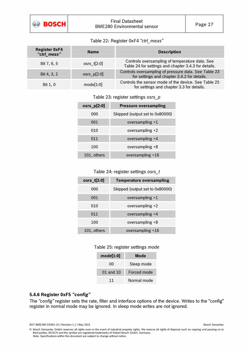
5.4.5 Register 0xF4 “ctrl_meas”
The “ctrl_meas” register sets the pressure and temperature data acquisition options of the device. The register needs to be written after changing “ctrl_hum” for the changes to become effective.
Final Datasheet
BME280 Environmental sensor Page 27
BST-BME280-DS001-10 | Revision 1.1 | May 2015 Bosch Sensortec
© Bosch Sensortec GmbH reserves all rights even in the event of industrial property rights. We reserve all rights of disposal such as copying and passing on to
third parties. BOSCH and the symbol are registered trademarks of Robert Bosch GmbH, Germany.
Note: Specifications within this document are subject to change without notice.
Table 22: Register 0xF4 “ctrl_meas”
Register 0xF4 “ctrl_meas”
Name Description
Bit 7, 6, 5 osrs_t[2:0] Controls oversampling of temperature data. See
Table 24 for settings and chapter 3.4.3 for details.
Bit 4, 3, 2 osrs_p[2:0] Controls oversampling of pressure data. See Table 23
for settings and chapter 3.4.2 for details.
Bit 1, 0 mode[1:0] Controls the sensor mode of the device. See Table 25
for settings and chapter 3.3 for details.
Table 23: register settings osrs_p
osrs_p[2:0] Pressure oversampling
000 Skipped (output set to 0x80000)
001 oversampling ×1
010 oversampling ×2
011 oversampling ×4
100 oversampling ×8
101, others oversampling ×16
Table 24: register settings osrs_t
osrs_t[2:0] Temperature oversampling
000 Skipped (output set to 0x80000)
001 oversampling ×1
010 oversampling ×2
011 oversampling ×4
100 oversampling ×8
101, others oversampling ×16
Table 25: register settings mode
mode[1:0] Mode
00 Sleep mode
01 and 10 Forced mode
11 Normal mode
5.4.6 Register 0xF5 “config”
The “config” register sets the rate, filter and interface options of the device. Writes to the “config” register in normal mode may be ignored. In sleep mode writes are not ignored.

Final Datasheet
BME280 Environmental sensor Page 28
BST-BME280-DS001-10 | Revision 1.1 | May 2015 Bosch Sensortec
© Bosch Sensortec GmbH reserves all rights even in the event of industrial property rights. We reserve all rights of disposal such as copying and passing on to
third parties. BOSCH and the symbol are registered trademarks of Robert Bosch GmbH, Germany.
Note: Specifications within this document are subject to change without notice.
Table 26: Register 0xF5 “config”
Register 0xF5 “config”
Name Description
Bit 7, 6, 5 t_sb[2:0] Controls inactive duration tstandby in normal mode. See
Table 27 for settings and chapter 3.3.4 for details.
Bit 4, 3, 2 filter[2:0] Controls the time constant of the IIR filter. See Table 27
for settings and chapter 3.4.4 for details.
Bit 0 spi3w_en[0] Enables 3-wire SPI interface when set to ‘1’. See
chapter 6.3 for details.
Table 27: t_sb settings
t_sb[2:0] tstandby [ms]
000 0.5
001 62.5
010 125
011 250
100 500
101 1000
110 10
111 20
Table 28: filter settings
filter[2:0] Filter coefficient
000 Filter off
001 2
010 4
011 8
100, others 16
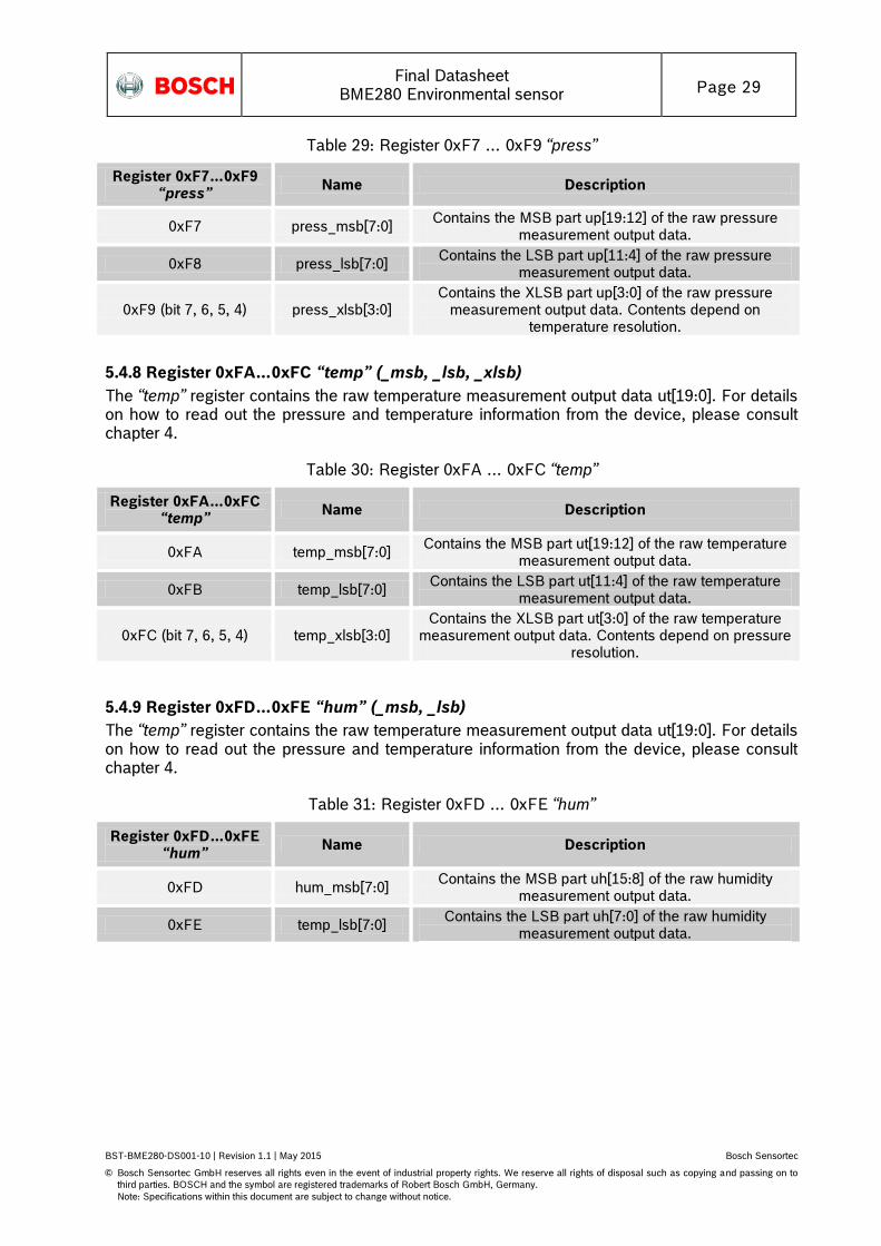
5.4.7 Register 0xF7…0xF9 “press” (_msb, _lsb, _xlsb)
The “press” register contains the raw pressure measurement output data up[19:0]. For details on how to read out the pressure and temperature information from the device, please consult chapter 4.
Final Datasheet
BME280 Environmental sensor Page 29
BST-BME280-DS001-10 | Revision 1.1 | May 2015 Bosch Sensortec
© Bosch Sensortec GmbH reserves all rights even in the event of industrial property rights. We reserve all rights of disposal such as copying and passing on to
third parties. BOSCH and the symbol are registered trademarks of Robert Bosch GmbH, Germany.
Note: Specifications within this document are subject to change without notice.
Table 29: Register 0xF7 … 0xF9 “press”
Register 0xF7…0xF9 “press”
Name Description
0xF7 press_msb[7:0] Contains the MSB part up[19:12] of the raw pressure
measurement output data.
0xF8 press_lsb[7:0] Contains the LSB part up[11:4] of the raw pressure
measurement output data.
0xF9 (bit 7, 6, 5, 4) press_xlsb[3:0] Contains the XLSB part up[3:0] of the raw pressure
measurement output data. Contents depend on temperature resolution.
5.4.8 Register 0xFA…0xFC “temp” (_msb, _lsb, _xlsb)
The “temp” register contains the raw temperature measurement output data ut[19:0]. For details on how to read out the pressure and temperature information from the device, please consult chapter 4.
Table 30: Register 0xFA … 0xFC “temp”
Register 0xFA…0xFC “temp”
Name Description
0xFA temp_msb[7:0] Contains the MSB part ut[19:12] of the raw temperature
measurement output data.
0xFB temp_lsb[7:0] Contains the LSB part ut[11:4] of the raw temperature
measurement output data.
0xFC (bit 7, 6, 5, 4) temp_xlsb[3:0] Contains the XLSB part ut[3:0] of the raw temperature
measurement output data. Contents depend on pressure resolution.
5.4.9 Register 0xFD…0xFE “hum” (_msb, _lsb)
The “temp” register contains the raw temperature measurement output data ut[19:0]. For details on how to read out the pressure and temperature information from the device, please consult chapter 4.
Table 31: Register 0xFD … 0xFE “hum”
Register 0xFD…0xFE “hum”
Name Description
0xFD hum_msb[7:0] Contains the MSB part uh[15:8] of the raw humidity
measurement output data.
0xFE temp_lsb[7:0] Contains the LSB part uh[7:0] of the raw humidity
measurement output data.
Final Datasheet
BME280 Environmental sensor Page 30
BST-BME280-DS001-10 | Revision 1.1 | May 2015 Bosch Sensortec
© Bosch Sensortec GmbH reserves all rights even in the event of industrial property rights. We reserve all rights of disposal such as copying and passing on to
third parties. BOSCH and the symbol are registered trademarks of Robert Bosch GmbH, Germany.
Note: Specifications within this document are subject to change without notice.
6. Digital interfaces The BME280 supports the I²C and SPI digital interfaces; it acts as a slave for both protocols. The I²C interface supports the Standard, Fast and High Speed modes. The SPI interface supports both SPI mode ‘00’ (CPOL = CPHA = ‘0’) and mode ‘11’ (CPOL = CPHA = ‘1’) in 4-wire and 3-wire configuration. The following transactions are supported:
Single byte write
multiple byte write (using pairs of register addresses and register data)
single byte read
multiple byte read (using a single register address which is auto-incremented)
6.1 Interface selection
Interface selection is done automatically based on CSB (chip select) status. If CSB is connected to VDDIO, the I²C interface is active. If CSB is pulled down, the SPI interface is activated. After CSB has been pulled down once (regardless of whether any clock cycle occurred), the I²C interface is disabled until the next power-on-reset. This is done in order to avoid inadvertently decoding SPI traffic to another slave as I²C data. Since the device startup is deferred until both VDD and VDDIO are established, there is no risk of incorrect protocol detection because of the power-up sequence used. However, if I²C is to be used and CSB is not directly connected to VDDIO but is instead connected to a programmable pin, it must be ensured that this pin already outputs the VDDIO level during power-on-reset of the device. If this is not the case, the device will be locked in SPI mode and not respond to I²C commands.
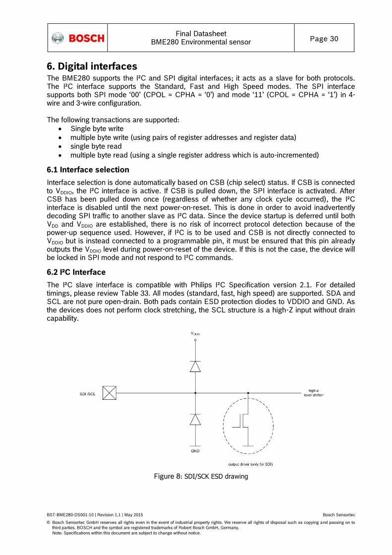
6.2 I²C Interface
The I²C slave interface is compatible with Philips I²C Specification version 2.1. For detailed timings, please review Table 33. All modes (standard, fast, high speed) are supported. SDA and SCL are not pure open-drain. Both pads contain ESD protection diodes to VDDIO and GND. As the devices does not perform clock stretching, the SCL structure is a high-Z input without drain capability.
Figure 8: SDI/SCK ESD drawing
Final Datasheet
BME280 Environmental sensor Page 31
BST-BME280-DS001-10 | Revision 1.1 | May 2015 Bosch Sensortec
© Bosch Sensortec GmbH reserves all rights even in the event of industrial property rights. We reserve all rights of disposal such as copying and passing on to
third parties. BOSCH and the symbol are registered trademarks of Robert Bosch GmbH, Germany.
Note: Specifications within this document are subject to change without notice.
The 7-bit device address is 111011x. The 6 MSB bits are fixed. The last bit is changeable by SDO value and can be changed during operation. Connecting SDO to GND results in slave address 1110110 (0x76); connection it to VDDIO results in slave address 1110111 (0x77), which is the same as BMP280’s I²C address. The SDO pin cannot be left floating; if left floating, the I²C address will be undefined. The I²C interface uses the following pins:
SCK: serial clock (SCL)
SDI: data (SDA)
SDO: Slave address LSB (GND = ‘0’, VDDIO = ‘1’) CSB must be connected to VDDIO to select I²C interface. SDI is bi-directional with open drain to GND: it must be externally connected to VDDIO via a pull up resistor. Refer to chapter 7 for connection instructions. The following abbreviations will be used in the I²C protocol figures:
S Start
P Stop
ACKS Acknowledge by slave
ACKM Acknowledge by master
NACKM Not acknowledge by master
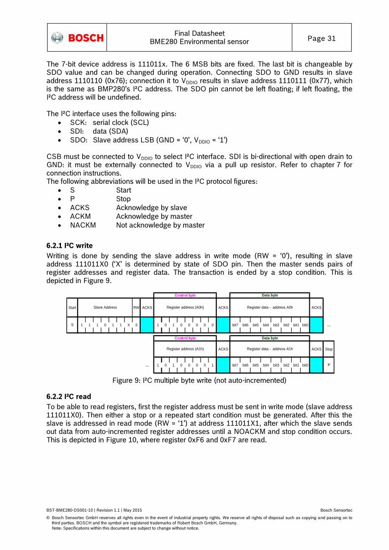
6.2.1 I²C write
Writing is done by sending the slave address in write mode (RW = ‘0’), resulting in slave address 111011X0 (‘X’ is determined by state of SDO pin. Then the master sends pairs of register addresses and register data. The transaction is ended by a stop condition. This is depicted in Figure 9.
Start RW ACKS ACKS ACKS
1 1 1 0 1 1 X 0 1 0 1 0 0 0 0 0 bit7 bit6 bit5 bit4 bit3 bit2 bit1 bit0 …
ACKS ACKS Stop
… 1 0 1 0 0 0 0 1 bit7 bit6 bit5 bit4 bit3 bit2 bit1 bit0
Register data - address A0hRegister address (A0h)
Register address (A1h)
S
Slave Address
Control byte Data byte
Control byte Data byte
P
Register data - address A1h
Figure 9: I²C multiple byte write (not auto-incremented)
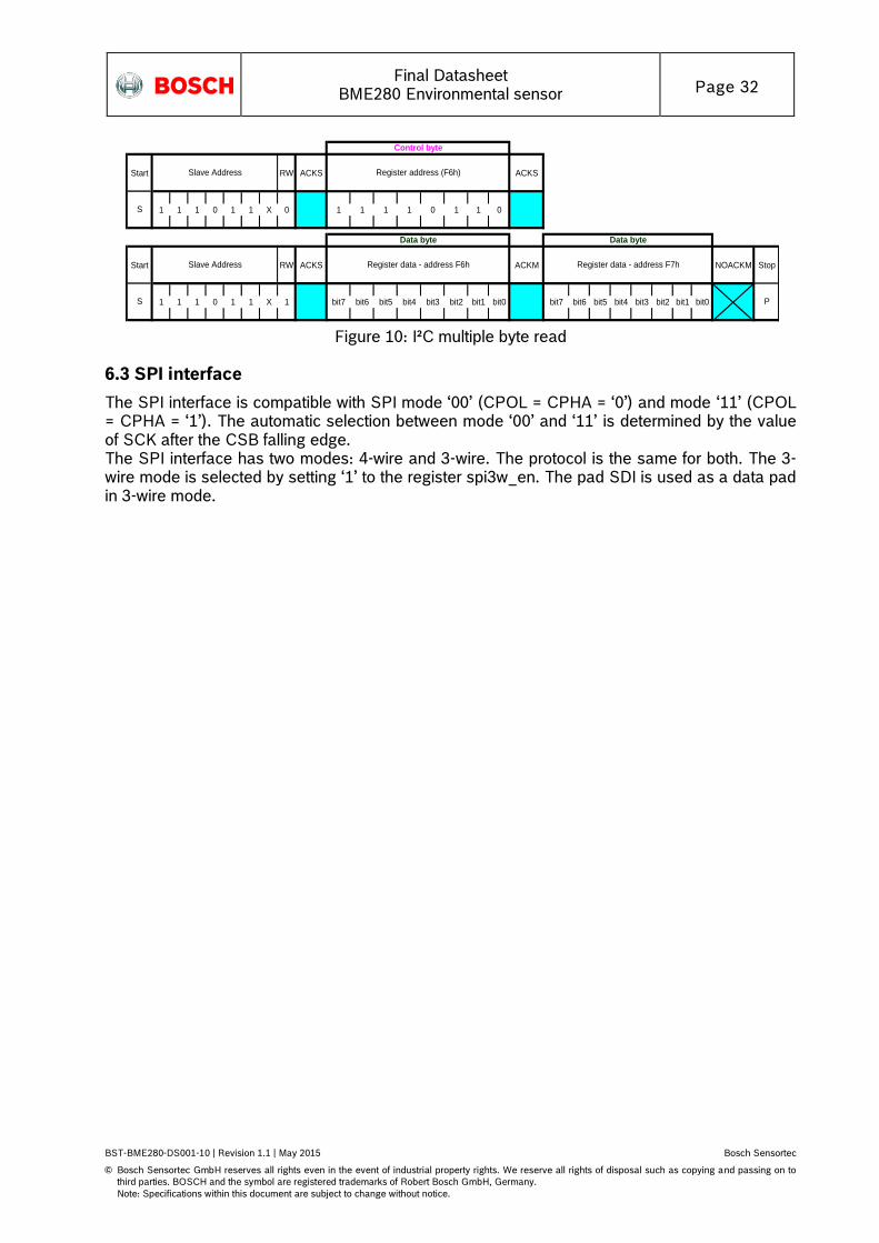
6.2.2 I²C read
To be able to read registers, first the register address must be sent in write mode (slave address 111011X0). Then either a stop or a repeated start condition must be generated. After this the slave is addressed in read mode (RW = ‘1’) at address 111011X1, after which the slave sends out data from auto-incremented register addresses until a NOACKM and stop condition occurs. This is depicted in Figure 10, where register 0xF6 and 0xF7 are read.
Final Datasheet
BME280 Environmental sensor Page 32
BST-BME280-DS001-10 | Revision 1.1 | May 2015 Bosch Sensortec
© Bosch Sensortec GmbH reserves all rights even in the event of industrial property rights. We reserve all rights of disposal such as copying and passing on to
third parties. BOSCH and the symbol are registered trademarks of Robert Bosch GmbH, Germany.
Note: Specifications within this document are subject to change without notice.
Start RW ACKS ACKS
1 1 1 0 1 1 X 0 1 1 1 1 0 1 1 0
Start RW ACKS ACKM NOACKM Stop
1 1 1 0 1 1 X 1 bit7 bit6 bit5 bit4 bit3 bit2 bit1 bit0 bit7 bit6 bit5 bit4 bit3 bit2 bit1 bit0
Control byte
Data byte Data byte
Register address (F6h)
S
Slave Address
PS
Slave Address Register data - address F7hRegister data - address F6h
Figure 10: I²C multiple byte read
6.3 SPI interface
The SPI interface is compatible with SPI mode ‘00’ (CPOL = CPHA = ‘0’) and mode ‘11’ (CPOL = CPHA = ‘1’). The automatic selection between mode ‘00’ and ‘11’ is determined by the value of SCK after the CSB falling edge. The SPI interface has two modes: 4-wire and 3-wire. The protocol is the same for both. The 3-wire mode is selected by setting ‘1’ to the register spi3w_en. The pad SDI is used as a data pad in 3-wire mode.
Final Datasheet
BME280 Environmental sensor Page 33
BST-BME280-DS001-10 | Revision 1.1 | May 2015 Bosch Sensortec
© Bosch Sensortec GmbH reserves all rights even in the event of industrial property rights. We reserve all rights of disposal such as copying and passing on to
third parties. BOSCH and the symbol are registered trademarks of Robert Bosch GmbH, Germany.
Note: Specifications within this document are subject to change without notice.
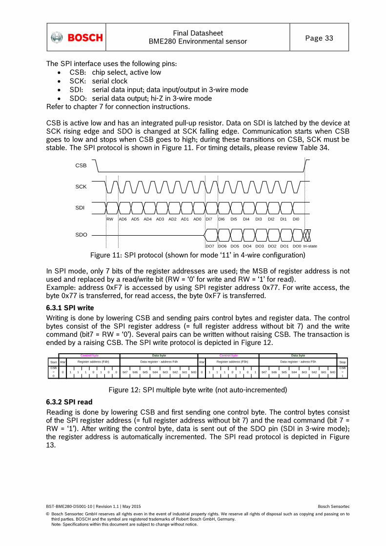
The SPI interface uses the following pins:
CSB: chip select, active low
SCK: serial clock
SDI: serial data input; data input/output in 3-wire mode
SDO: serial data output; hi-Z in 3-wire mode Refer to chapter 7 for connection instructions. CSB is active low and has an integrated pull-up resistor. Data on SDI is latched by the device at SCK rising edge and SDO is changed at SCK falling edge. Communication starts when CSB goes to low and stops when CSB goes to high; during these transitions on CSB, SCK must be stable. The SPI protocol is shown in Figure 11. For timing details, please review Table 34.
CSB
SCK
SDI
RW AD6 AD5 AD4 AD3 AD2 AD1 AD0 DI5 DI4 DI3 DI2 DI1 DI0 DI7 DI6
SDO
DO5 DO4 DO3 DO2 DO1 DO0 DO7 DO6 tri-state Figure 11: SPI protocol (shown for mode ‘11’ in 4-wire configuration)
In SPI mode, only 7 bits of the register addresses are used; the MSB of register address is not used and replaced by a read/write bit (RW = ‘0’ for write and RW = ‘1’ for read). Example: address 0xF7 is accessed by using SPI register address 0x77. For write access, the byte 0x77 is transferred, for read access, the byte 0xF7 is transferred.
6.3.1 SPI write
Writing is done by lowering CSB and sending pairs control bytes and register data. The control bytes consist of the SPI register address (= full register address without bit 7) and the write command (bit7 = RW = ‘0’). Several pairs can be written without raising CSB. The transaction is ended by a raising CSB. The SPI write protocol is depicted in Figure 12.
Start RW RW Stop
0 1 1 1 0 1 0 0 bit7 bit6 bit5 bit4 bit3 bit2 bit1 bit0 0 1 1 1 0 1 0 1 bit7 bit6 bit5 bit4 bit3 bit2 bit1 bit0
Control byte
CSB
=
1
Data byte
Register address (F5h) Data register - adress F5hRegister address (F4h)
CSB
=
0
Control byte Data byte
Data register - address F4h
Figure 12: SPI multiple byte write (not auto-incremented)
6.3.2 SPI read
Reading is done by lowering CSB and first sending one control byte. The control bytes consist of the SPI register address (= full register address without bit 7) and the read command (bit 7 = RW = ‘1’). After writing the control byte, data is sent out of the SDO pin (SDI in 3-wire mode); the register address is automatically incremented. The SPI read protocol is depicted in Figure 13.
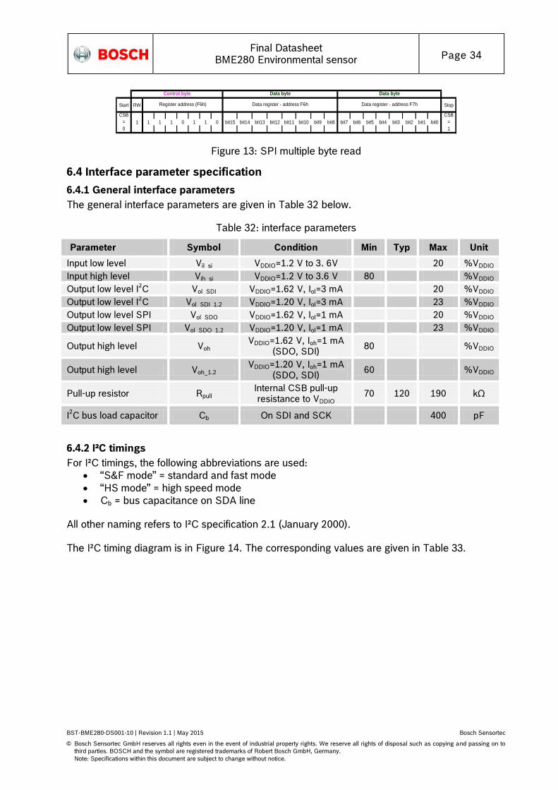
Final Datasheet
BME280 Environmental sensor Page 34
BST-BME280-DS001-10 | Revision 1.1 | May 2015 Bosch Sensortec
© Bosch Sensortec GmbH reserves all rights even in the event of industrial property rights. We reserve all rights of disposal such as copying and passing on to
third parties. BOSCH and the symbol are registered trademarks of Robert Bosch GmbH, Germany.
Note: Specifications within this document are subject to change without notice.
Start RW Stop
1 1 1 1 0 1 1 0 bit15 bit14 bit13 bit12 bit11 bit10 bit9 bit8 bit7 bit6 bit5 bit4 bit3 bit2 bit1 bit0
CSB
=
1
Data byte
Data register - address F7hRegister address (F6h)
CSB
=
0
Control byte Data byte
Data register - address F6h
Figure 13: SPI multiple byte read
6.4 Interface parameter specification
6.4.1 General interface parameters
The general interface parameters are given in Table 32 below.
Table 32: interface parameters
Parameter Symbol Condition Min Typ Max Unit
Input low level Vil_si VDDIO=1.2 V to 3. 6V 20 %VDDIO
Input high level Vih_si VDDIO=1.2 V to 3.6 V 80 %VDDIO
Output low level I2C Vol_SDI VDDIO=1.62 V, Iol=3 mA 20 %VDDIO
Output low level I2C Vol_SDI_1.2 VDDIO=1.20 V, Iol=3 mA 23 %VDDIO
Output low level SPI Vol_SDO VDDIO=1.62 V, Iol=1 mA 20 %VDDIO
Output low level SPI Vol_SDO_1.2 VDDIO=1.20 V, Iol=1 mA 23 %VDDIO
Output high level Voh VDDIO=1.62 V, Ioh=1 mA
(SDO, SDI) 80 %VDDIO
Output high level Voh_1.2 VDDIO=1.20 V, Ioh=1 mA
(SDO, SDI) 60 %VDDIO
Pull-up resistor Rpull Internal CSB pull-up resistance to VDDIO
70 120 190 kΩ
I2C bus load capacitor Cb On SDI and SCK 400 pF
6.4.2 I²C timings
For I²C timings, the following abbreviations are used:
“S&F mode” = standard and fast mode
“HS mode” = high speed mode
Cb = bus capacitance on SDA line
All other naming refers to I²C specification 2.1 (January 2000). The I²C timing diagram is in Figure 14. The corresponding values are given in Table 33.
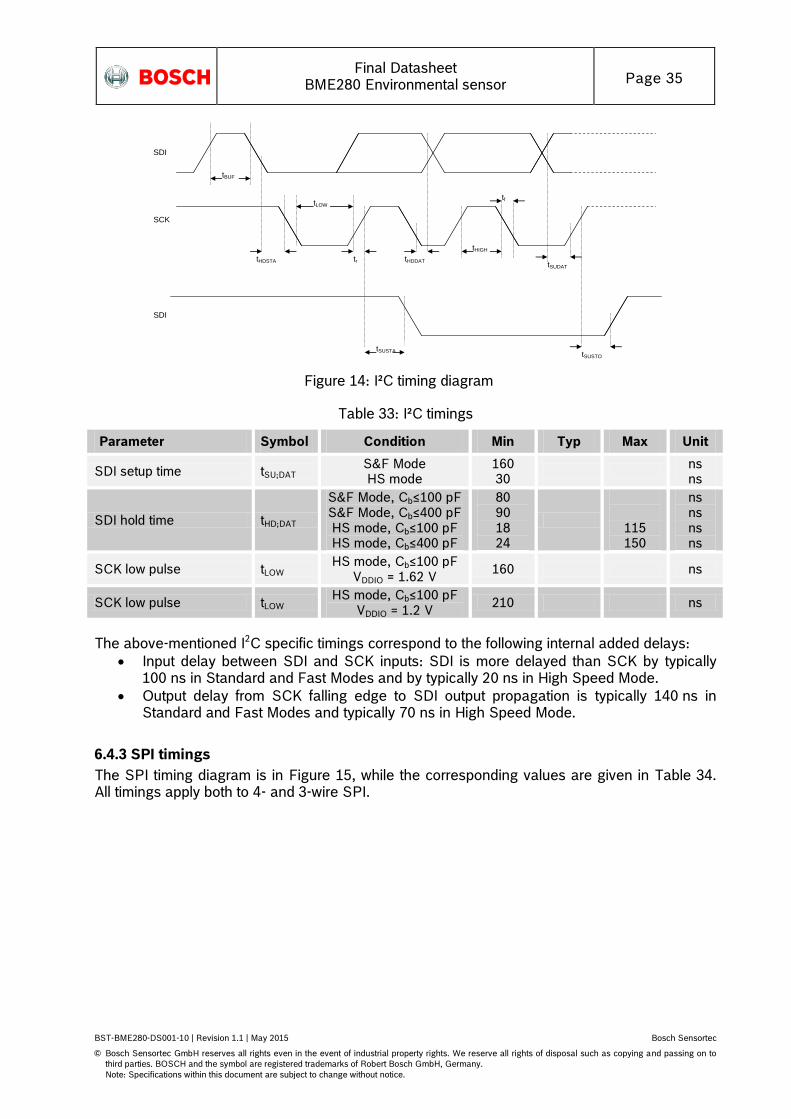
Final Datasheet
BME280 Environmental sensor Page 35
BST-BME280-DS001-10 | Revision 1.1 | May 2015 Bosch Sensortec
© Bosch Sensortec GmbH reserves all rights even in the event of industrial property rights. We reserve all rights of disposal such as copying and passing on to
third parties. BOSCH and the symbol are registered trademarks of Robert Bosch GmbH, Germany.
Note: Specifications within this document are subject to change without notice.
tHDDAT
tf
tBUF
SDI
SCK
SDI
tLOW
tHDSTA tr
tSUSTA
tHIGH
tSUDAT
tSUSTO
Figure 14: I²C timing diagram
Table 33: I²C timings
Parameter Symbol Condition Min Typ Max Unit
SDI setup time tSU;DAT S&F Mode HS mode
160 30
ns ns
SDI hold time tHD;DAT
S&F Mode, Cb≤100 pF S&F Mode, Cb≤400 pF HS mode, Cb≤100 pF HS mode, Cb≤400 pF
80 90 18 24
115 150
ns ns ns ns
SCK low pulse tLOW HS mode, Cb≤100 pF
VDDIO = 1.62 V 160 ns
SCK low pulse tLOW HS mode, Cb≤100 pF
VDDIO = 1.2 V 210 ns
The above-mentioned I2C specific timings correspond to the following internal added delays:
Input delay between SDI and SCK inputs: SDI is more delayed than SCK by typically 100 ns in Standard and Fast Modes and by typically 20 ns in High Speed Mode.
Output delay from SCK falling edge to SDI output propagation is typically 140 ns in Standard and Fast Modes and typically 70 ns in High Speed Mode.
6.4.3 SPI timings
The SPI timing diagram is in Figure 15, while the corresponding values are given in Table 34. All timings apply both to 4- and 3-wire SPI.
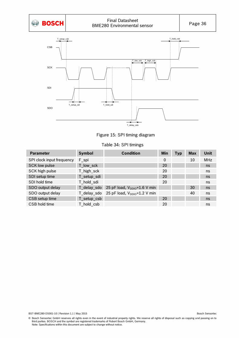
Final Datasheet
BME280 Environmental sensor Page 36
BST-BME280-DS001-10 | Revision 1.1 | May 2015 Bosch Sensortec
© Bosch Sensortec GmbH reserves all rights even in the event of industrial property rights. We reserve all rights of disposal such as copying and passing on to
third parties. BOSCH and the symbol are registered trademarks of Robert Bosch GmbH, Germany.
Note: Specifications within this document are subject to change without notice.
CSB
SCK
T_setup_csb
T_low_sck T_high_sck
T_hold_csb
SDI
T_setup_sdi T_hold_sdi
SDO
T_delay_sdo
Figure 15: SPI timing diagram
Table 34: SPI timings
Parameter Symbol Condition Min Typ Max Unit
SPI clock input frequency F_spi 0 10 MHz
SCK low pulse T_low_sck 20 ns
SCK high pulse T_high_sck 20 ns
SDI setup time T_setup_sdi 20 ns
SDI hold time T_hold_sdi 20 ns
SDO output delay T_delay_sdo 25 pF load, VDDIO=1.6 V min 30 ns
SDO output delay T_delay_sdo 25 pF load, VDDIO=1.2 V min 40 ns
CSB setup time T_setup_csb 20 ns
CSB hold time T_hold_csb 20 ns
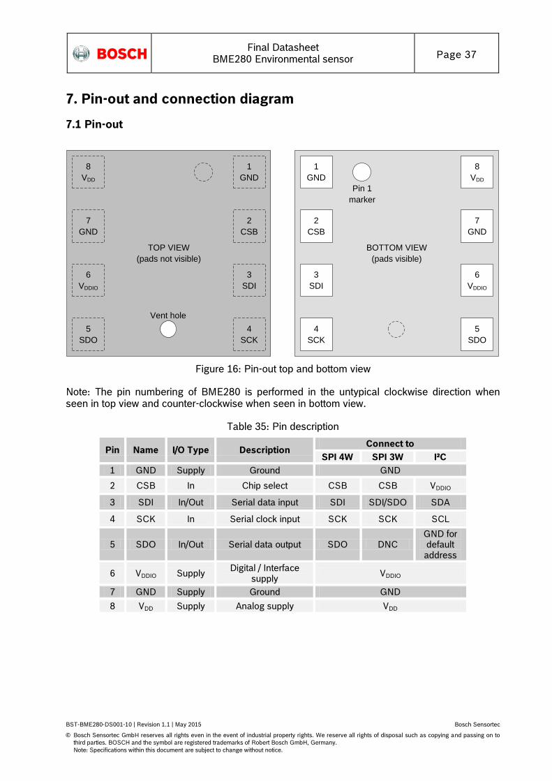
Final Datasheet
BME280 Environmental sensor Page 37
BST-BME280-DS001-10 | Revision 1.1 | May 2015 Bosch Sensortec
© Bosch Sensortec GmbH reserves all rights even in the event of industrial property rights. We reserve all rights of disposal such as copying and passing on to
third parties. BOSCH and the symbol are registered trademarks of Robert Bosch GmbH, Germany.
Note: Specifications within this document are subject to change without notice.
7. Pin-out and connection diagram
7.1 Pin-out
TOP VIEW
(pads not visible)
8
VDD
7
GND
6
VDDIO
5
SDO
BOTTOM VIEW
(pads visible)
1
GND
2
CSB
3
SDI
4
SCK
Pin 1
marker
1
GND
2
CSB
3
SDI
4
SCK
8
VDD
7
GND
6
VDDIO
5
SDO
Vent hole
Figure 16: Pin-out top and bottom view
Note: The pin numbering of BME280 is performed in the untypical clockwise direction when seen in top view and counter-clockwise when seen in bottom view.
Table 35: Pin description
Pin Name I/O Type Description Connect to
SPI 4W SPI 3W I²C
1 GND Supply Ground GND
2 CSB In Chip select CSB CSB VDDIO
3 SDI In/Out Serial data input SDI SDI/SDO SDA
4 SCK In Serial clock input SCK SCK SCL
5 SDO In/Out Serial data output SDO DNC GND for default address
6 VDDIO Supply Digital / Interface
supply VDDIO
7 GND Supply Ground GND
8 VDD Supply Analog supply VDD

Final Datasheet
BME280 Environmental sensor Page 38
BST-BME280-DS001-10 | Revision 1.1 | May 2015 Bosch Sensortec
© Bosch Sensortec GmbH reserves all rights even in the event of industrial property rights. We reserve all rights of disposal such as copying and passing on to
third parties. BOSCH and the symbol are registered trademarks of Robert Bosch GmbH, Germany.
Note: Specifications within this document are subject to change without notice.
7.2 Connection diagram I2C
I2C address bit 0
GND: '0'; VDDIO: '1'
TOP VIEW
(pads not visible)
8
VDD
7
GND
6
VDDIO
5
SDO
C1
VDDIOVDD
C2
1
GND
2
CSB
3
SDI
4
SCK
SDA
SCL
Vent hole
R2R1
Figure 17: I²C connection diagram
Notes:
The recommended value for C1, C2 is 100 nF
The value for the pull-up resistors R1, R2 should be based on the interface timing and the bus load; a normal value is 4.7 kΩ
A direct connection between CSB and VDDIO is required
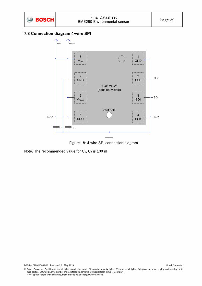
Final Datasheet
BME280 Environmental sensor Page 39
BST-BME280-DS001-10 | Revision 1.1 | May 2015 Bosch Sensortec
© Bosch Sensortec GmbH reserves all rights even in the event of industrial property rights. We reserve all rights of disposal such as copying and passing on to
third parties. BOSCH and the symbol are registered trademarks of Robert Bosch GmbH, Germany.
Note: Specifications within this document are subject to change without notice.
7.3 Connection diagram 4-wire SPI
SDO
TOP VIEW
(pads not visible)
8
VDD
7
GND
6
VDDIO
5
SDO
C1
VDDIOVDD
C2
1
GND
2
CSB
3
SDI
4
SCK
SDI
SCK
CSB
Vent hole
Figure 18: 4-wire SPI connection diagram
Note: The recommended value for C1, C2 is 100 nF

Final Datasheet
BME280 Environmental sensor Page 40
BST-BME280-DS001-10 | Revision 1.1 | May 2015 Bosch Sensortec
© Bosch Sensortec GmbH reserves all rights even in the event of industrial property rights. We reserve all rights of disposal such as copying and passing on to
third parties. BOSCH and the symbol are registered trademarks of Robert Bosch GmbH, Germany.
Note: Specifications within this document are subject to change without notice.
7.4 Connection diagram 3-wire SPI
TOP VIEW
(pads not visible)
8
VDD
7
GND
6
VDDIO
5
SDO
C1
VDDIOVDD
C2
1
GND
2
CSB
3
SDI
4
SCK
SDI/SDO
SCK
CSB
Vent hole
Figure 19: 3-wire SPI connection diagram
Note: The recommended value for C1, C2 is 100 nF
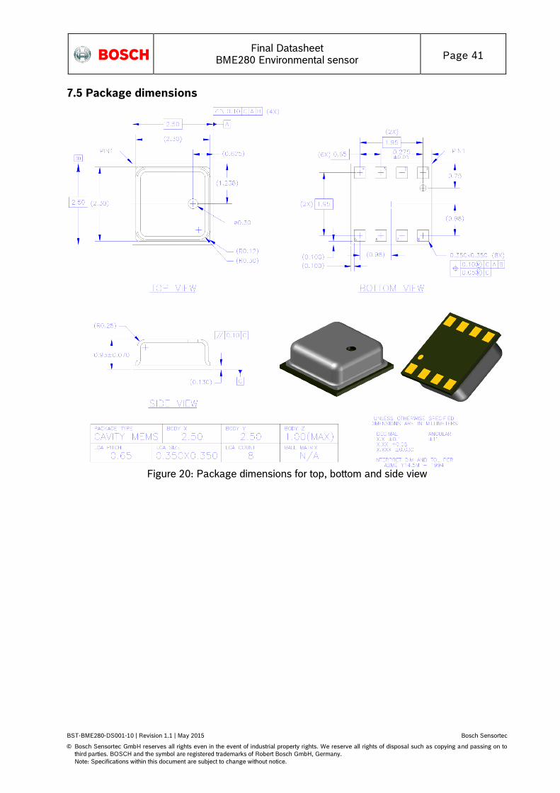
Final Datasheet
BME280 Environmental sensor Page 41
BST-BME280-DS001-10 | Revision 1.1 | May 2015 Bosch Sensortec
© Bosch Sensortec GmbH reserves all rights even in the event of industrial property rights. We reserve all rights of disposal such as copying and passing on to
third parties. BOSCH and the symbol are registered trademarks of Robert Bosch GmbH, Germany.
Note: Specifications within this document are subject to change without notice.
7.5 Package dimensions
Figure 20: Package dimensions for top, bottom and side view

Final Datasheet
BME280 Environmental sensor Page 42
BST-BME280-DS001-10 | Revision 1.1 | May 2015 Bosch Sensortec
© Bosch Sensortec GmbH reserves all rights even in the event of industrial property rights. We reserve all rights of disposal such as copying and passing on to
third parties. BOSCH and the symbol are registered trademarks of Robert Bosch GmbH, Germany.
Note: Specifications within this document are subject to change without notice.
7.6 Landing pattern recommendation
For the design of the landing pattern, the following dimensioning is recommended:
Figure 21: Recommended landing pattern (top view)
Note: red areas demark exposed PCB metal pads.
In case of a solder mask defined (SMD) PCB process, the land dimensions should be defined by solder mask openings. The underlying metal pads are larger than these openings.
In case of a non solder mask defined (NSMD) PCB process, the land dimensions should be defined in the metal layer. The mask openings are larger than these metal pads.
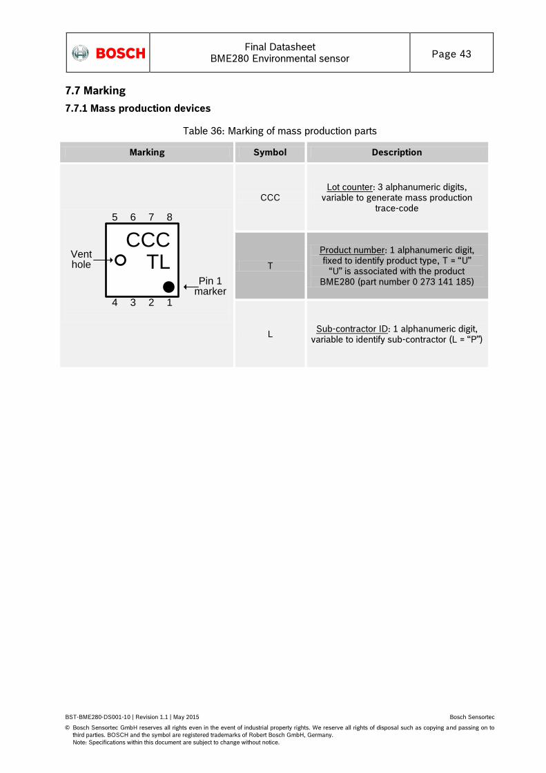
Final Datasheet
BME280 Environmental sensor Page 43
BST-BME280-DS001-10 | Revision 1.1 | May 2015 Bosch Sensortec
© Bosch Sensortec GmbH reserves all rights even in the event of industrial property rights. We reserve all rights of disposal such as copying and passing on to
third parties. BOSCH and the symbol are registered trademarks of Robert Bosch GmbH, Germany.
Note: Specifications within this document are subject to change without notice.
7.7 Marking
7.7.1 Mass production devices
Table 36: Marking of mass production parts
Marking Symbol Description
CCCTL
5 6 7 8
4 3 2 1
Venthole
Pin 1marker
CCC Lot counter: 3 alphanumeric digits,
variable to generate mass production trace-code
T
Product number: 1 alphanumeric digit, fixed to identify product type, T = “U”
“U” is associated with the product BME280 (part number 0 273 141 185)
L Sub-contractor ID: 1 alphanumeric digit,
variable to identify sub-contractor (L = “P”)
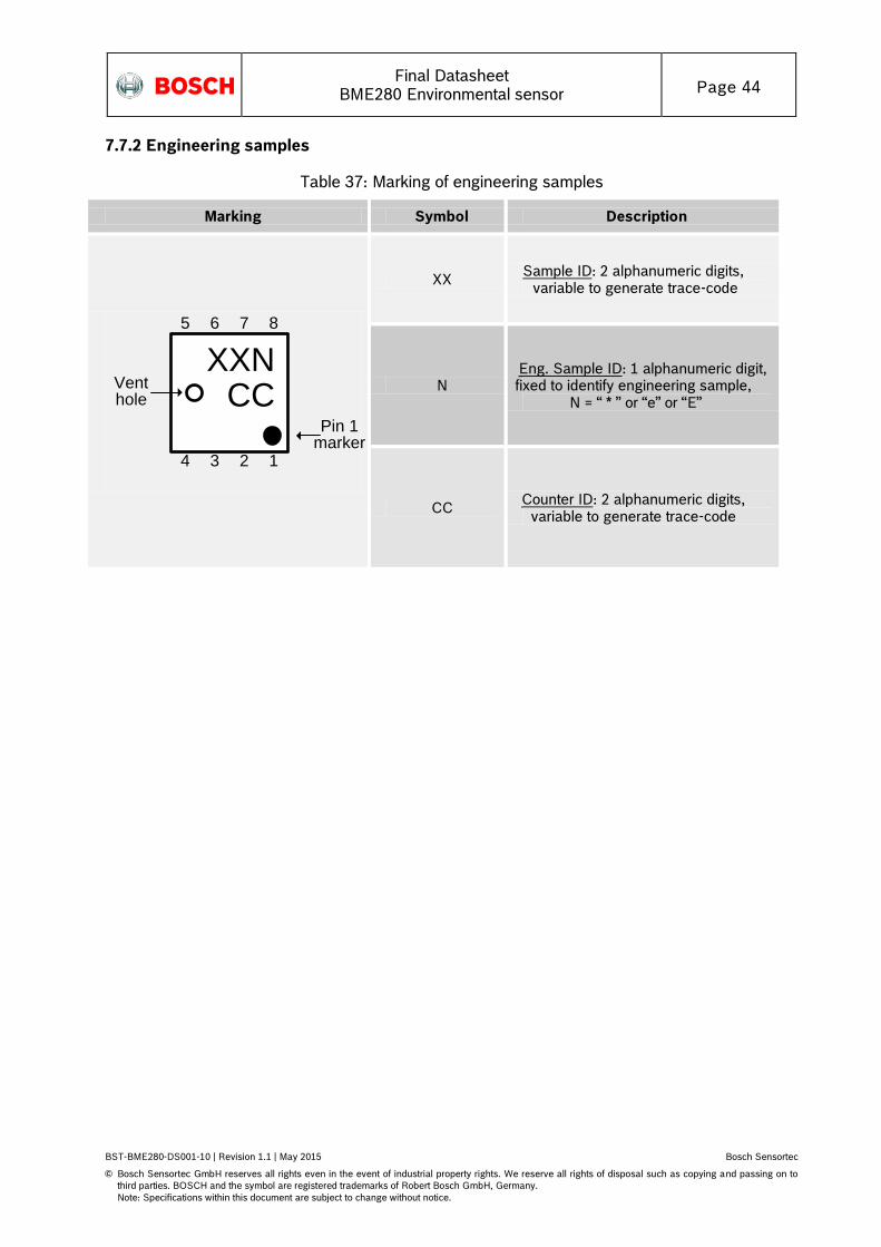
Final Datasheet
BME280 Environmental sensor Page 44
BST-BME280-DS001-10 | Revision 1.1 | May 2015 Bosch Sensortec
© Bosch Sensortec GmbH reserves all rights even in the event of industrial property rights. We reserve all rights of disposal such as copying and passing on to
third parties. BOSCH and the symbol are registered trademarks of Robert Bosch GmbH, Germany.
Note: Specifications within this document are subject to change without notice.
7.7.2 Engineering samples
Table 37: Marking of engineering samples
Marking Symbol Description
XXNCC
5 6 7 8
4 3 2 1
Venthole
Pin 1marker
XX Sample ID: 2 alphanumeric digits, variable to generate trace-code
N Eng. Sample ID: 1 alphanumeric digit, fixed to identify engineering sample,
N = “ * ” or “e” or “E”
CC Counter ID: 2 alphanumeric digits,
variable to generate trace-code
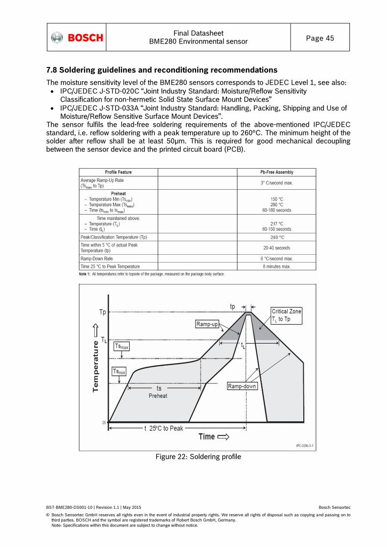
Final Datasheet
BME280 Environmental sensor Page 45
BST-BME280-DS001-10 | Revision 1.1 | May 2015 Bosch Sensortec
© Bosch Sensortec GmbH reserves all rights even in the event of industrial property rights. We reserve all rights of disposal such as copying and passing on to
third parties. BOSCH and the symbol are registered trademarks of Robert Bosch GmbH, Germany.
Note: Specifications within this document are subject to change without notice.
7.8 Soldering guidelines and reconditioning recommendations
The moisture sensitivity level of the BME280 sensors corresponds to JEDEC Level 1, see also:
IPC/JEDEC J-STD-020C “Joint Industry Standard: Moisture/Reflow Sensitivity Classification for non-hermetic Solid State Surface Mount Devices”
IPC/JEDEC J-STD-033A “Joint Industry Standard: Handling, Packing, Shipping and Use of Moisture/Reflow Sensitive Surface Mount Devices”.
The sensor fulfils the lead-free soldering requirements of the above-mentioned IPC/JEDEC standard, i.e. reflow soldering with a peak temperature up to 260°C. The minimum height of the solder after reflow shall be at least 50µm. This is required for good mechanical decoupling between the sensor device and the printed circuit board (PCB).
Figure 22: Soldering profile
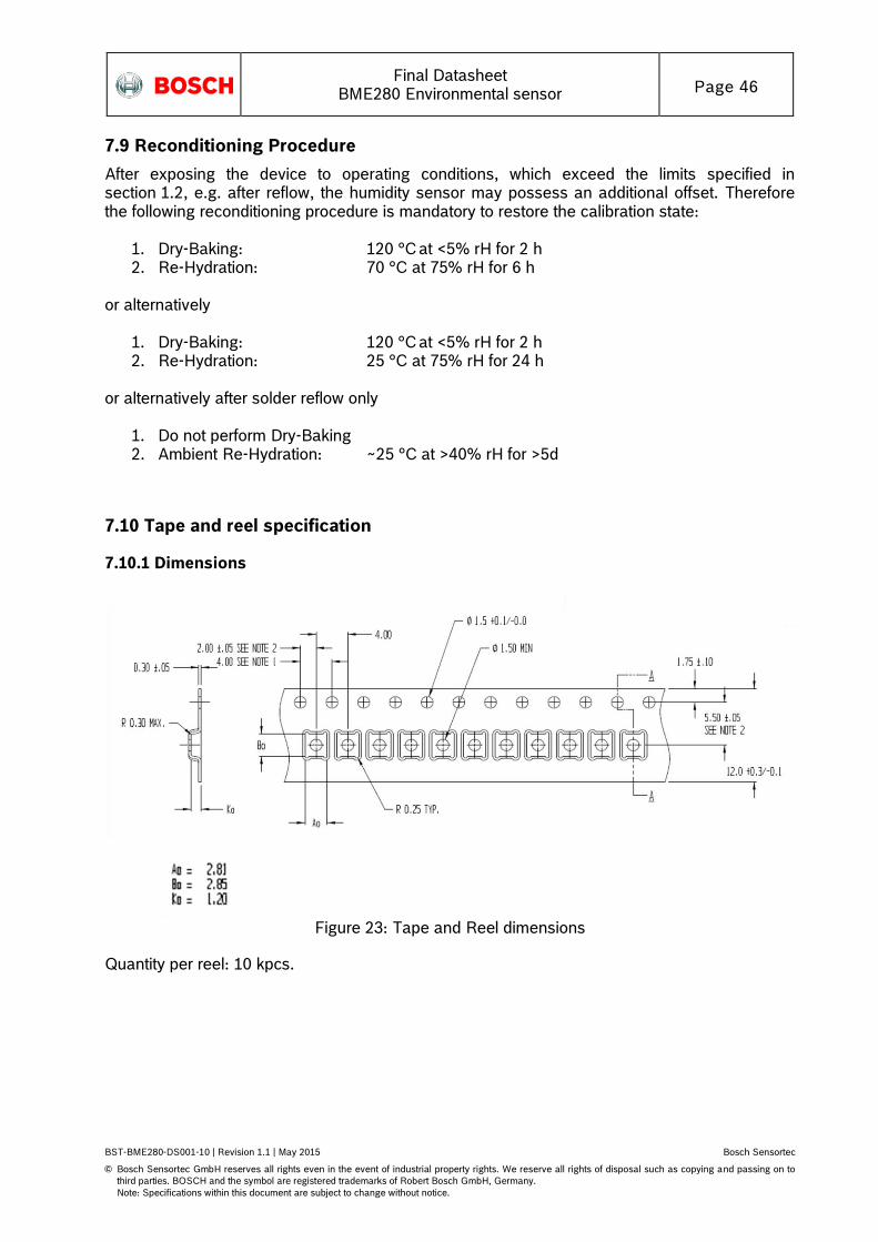
Final Datasheet
BME280 Environmental sensor Page 46
BST-BME280-DS001-10 | Revision 1.1 | May 2015 Bosch Sensortec
© Bosch Sensortec GmbH reserves all rights even in the event of industrial property rights. We reserve all rights of disposal such as copying and passing on to
third parties. BOSCH and the symbol are registered trademarks of Robert Bosch GmbH, Germany.
Note: Specifications within this document are subject to change without notice.
7.9 Reconditioning Procedure
After exposing the device to operating conditions, which exceed the limits specified in section 1.2, e.g. after reflow, the humidity sensor may possess an additional offset. Therefore the following reconditioning procedure is mandatory to restore the calibration state:
1. Dry-Baking: 120 °C at <5% rH for 2 h 2. Re-Hydration: 70 °C at 75% rH for 6 h
or alternatively
1. Dry-Baking: 120 °C at <5% rH for 2 h 2. Re-Hydration: 25 °C at 75% rH for 24 h
or alternatively after solder reflow only
1. Do not perform Dry-Baking 2. Ambient Re-Hydration: ~25 °C at >40% rH for >5d
7.10 Tape and reel specification
7.10.1 Dimensions
Figure 23: Tape and Reel dimensions
Quantity per reel: 10 kpcs.
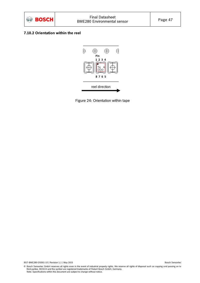
Final Datasheet
BME280 Environmental sensor Page 47
BST-BME280-DS001-10 | Revision 1.1 | May 2015 Bosch Sensortec
© Bosch Sensortec GmbH reserves all rights even in the event of industrial property rights. We reserve all rights of disposal such as copying and passing on to
third parties. BOSCH and the symbol are registered trademarks of Robert Bosch GmbH, Germany.
Note: Specifications within this document are subject to change without notice.
7.10.2 Orientation within the reel
Figure 24: Orientation within tape
Final Datasheet
BME280 Environmental sensor Page 48
BST-BME280-DS001-10 | Revision 1.1 | May 2015 Bosch Sensortec
© Bosch Sensortec GmbH reserves all rights even in the event of industrial property rights. We reserve all rights of disposal such as copying and passing on to
third parties. BOSCH and the symbol are registered trademarks of Robert Bosch GmbH, Germany.
Note: Specifications within this document are subject to change without notice.
7.11 Mounting and assembly recommendations
In order to achieve the specified performance for you design, the following recommendations and the “Handling, soldering & mounting instructions BME280” should be taken into consideration when mounting a pressure sensor on a printed-circuit board (PCB):
The clearance above the metal lid shall be 0.1mm at minimum.
For the device housing appropriate venting needs to be provided in case the ambient pressure shall be measured.
Liquids shall not come into direct contact with the device.
During operation the sensor chip is sensitive to light, which can influence the accuracy of the measurement (photo-current of silicon). The position of the vent hole minimizes the light exposure of the sensor chip. Nevertheless, Bosch Sensortec recommends avoiding the exposure of BME280 to strong light sources.
Soldering may not be done using vapor phase processes since the sensor will be damaged by the liquids used in these processes.
7.12 Environmental safety
7.12.1 RoHS
The BME280 sensor meets the requirements of the EC restriction of hazardous substances (RoHS) directive, see also:
Directive 2011/65/EU of the European Parliament and of the Council of 8 June 2011 on the restriction of the use of certain hazardous substances in electrical and electronic equipment.
7.12.2 Halogen content
The BME280 is halogen-free. For more details on the analysis results please contact your Bosch Sensortec representative.
7.12.3 Internal package structure
Within the scope of Bosch Sensortec’s ambition to improve its products and secure the mass product supply, Bosch Sensortec qualifies additional sources (e.g. 2nd source) for the package of the BME280. While Bosch Sensortec took care that all of the technical packages parameters are described above are 100% identical for all sources, there can be differences in the chemical content and the internal structural between the different package sources. However, as secured by the extensive product qualification process of Bosch Sensortec, this has no impact to the usage or to the quality of the BME280 product.
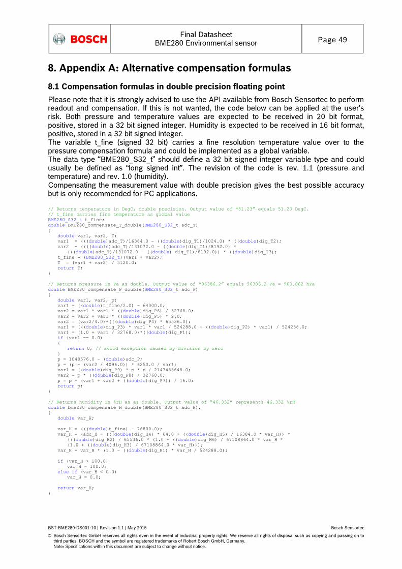
Final Datasheet
BME280 Environmental sensor Page 49
BST-BME280-DS001-10 | Revision 1.1 | May 2015 Bosch Sensortec
© Bosch Sensortec GmbH reserves all rights even in the event of industrial property rights. We reserve all rights of disposal such as copying and passing on to
third parties. BOSCH and the symbol are registered trademarks of Robert Bosch GmbH, Germany.
Note: Specifications within this document are subject to change without notice.
8. Appendix A: Alternative compensation formulas
8.1 Compensation formulas in double precision floating point
Please note that it is strongly advised to use the API available from Bosch Sensortec to perform readout and compensation. If this is not wanted, the code below can be applied at the user’s risk. Both pressure and temperature values are expected to be received in 20 bit format, positive, stored in a 32 bit signed integer. Humidity is expected to be received in 16 bit format, positive, stored in a 32 bit signed integer. The variable t_fine (signed 32 bit) carries a fine resolution temperature value over to the pressure compensation formula and could be implemented as a global variable. The data type “BME280_S32_t” should define a 32 bit signed integer variable type and could usually be defined as “long signed int”. The revision of the code is rev. 1.1 (pressure and temperature) and rev. 1.0 (humidity). Compensating the measurement value with double precision gives the best possible accuracy but is only recommended for PC applications. // Returns temperature in DegC, double precision. Output value of “51.23” equals 51.23 DegC.
// t_fine carries fine temperature as global value
BME280_S32_t t_fine;
double BME280_compensate_T_double(BME280_S32_t adc_T)
double var1, var2, T;
var1 = (((double)adc_T)/16384.0 – ((double)dig_T1)/1024.0) * ((double)dig_T2);
var2 = ((((double)adc_T)/131072.0 – ((double)dig_T1)/8192.0) *
(((double)adc_T)/131072.0 – ((double) dig_T1)/8192.0)) * ((double)dig_T3);
t_fine = (BME280_S32_t)(var1 + var2);
T = (var1 + var2) / 5120.0;
return T;
// Returns pressure in Pa as double. Output value of “96386.2” equals 96386.2 Pa = 963.862 hPa
double BME280_compensate_P_double(BME280_S32_t adc_P)
double var1, var2, p;
var1 = ((double)t_fine/2.0) – 64000.0;
var2 = var1 * var1 * ((double)dig_P6) / 32768.0;
var2 = var2 + var1 * ((double)dig_P5) * 2.0;
var2 = (var2/4.0)+(((double)dig_P4) * 65536.0);
var1 = (((double)dig_P3) * var1 * var1 / 524288.0 + ((double)dig_P2) * var1) / 524288.0;
var1 = (1.0 + var1 / 32768.0)*((double)dig_P1);
if (var1 == 0.0)
return 0; // avoid exception caused by division by zero
p = 1048576.0 – (double)adc_P;
p = (p – (var2 / 4096.0)) * 6250.0 / var1;
var1 = ((double)dig_P9) * p * p / 2147483648.0;
var2 = p * ((double)dig_P8) / 32768.0;
p = p + (var1 + var2 + ((double)dig_P7)) / 16.0;
return p;
// Returns humidity in %rH as as double. Output value of “46.332” represents 46.332 %rH
double bme280_compensate_H_double(BME280_S32_t adc_H);
double var_H;
var_H = (((double)t_fine) – 76800.0);
var_H = (adc_H – (((double)dig_H4) * 64.0 + ((double)dig_H5) / 16384.0 * var_H)) *
(((double)dig_H2) / 65536.0 * (1.0 + ((double)dig_H6) / 67108864.0 * var_H *
(1.0 + ((double)dig_H3) / 67108864.0 * var_H)));
var_H = var_H * (1.0 – ((double)dig_H1) * var_H / 524288.0);
if (var_H > 100.0)
var_H = 100.0;
else if (var_H < 0.0)
var_H = 0.0;
return var_H;
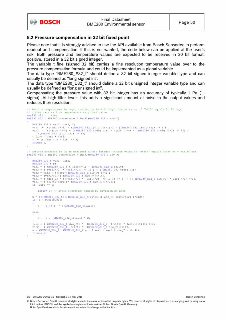
Final Datasheet
BME280 Environmental sensor Page 50
BST-BME280-DS001-10 | Revision 1.1 | May 2015 Bosch Sensortec
© Bosch Sensortec GmbH reserves all rights even in the event of industrial property rights. We reserve all rights of disposal such as copying and passing on to
third parties. BOSCH and the symbol are registered trademarks of Robert Bosch GmbH, Germany.
Note: Specifications within this document are subject to change without notice.
8.2 Pressure compensation in 32 bit fixed point
Please note that it is strongly advised to use the API available from Bosch Sensortec to perform readout and compensation. If this is not wanted, the code below can be applied at the user’s risk. Both pressure and temperature values are expected to be received in 20 bit format, positive, stored in a 32 bit signed integer. The variable t_fine (signed 32 bit) carries a fine resolution temperature value over to the pressure compensation formula and could be implemented as a global variable. The data type “BME280_S32_t” should define a 32 bit signed integer variable type and can usually be defined as “long signed int”. The data type “BME280_U32_t” should define a 32 bit unsigned integer variable type and can usually be defined as “long unsigned int”. Compensating the pressure value with 32 bit integer has an accuracy of typically 1 Pa (1-sigma). At high filter levels this adds a significant amount of noise to the output values and reduces their resolution.
// Returns temperature in DegC, resolution is 0.01 DegC. Output value of “5123” equals 51.23 DegC.
// t_fine carries fine temperature as global value
BME280_S32_t t_fine;
BME280_S32_t BME280_compensate_T_int32(BME280_S32_t adc_T)
BME280_S32_t var1, var2, T;
var1 = ((((adc_T>>3) – ((BME280_S32_t)dig_T1<<1))) * ((BME280_S32_t)dig_T2)) >> 11;
var2 = (((((adc_T>>4) – ((BME280_S32_t)dig_T1)) * ((adc_T>>4) – ((BME280_S32_t)dig_T1))) >> 12) *
((BME280_S32_t)dig_T3)) >> 14;
t_fine = var1 + var2;
T = (t_fine * 5 + 128) >> 8;
return T;
// Returns pressure in Pa as unsigned 32 bit integer. Output value of “96386” equals 96386 Pa = 963.86 hPa
BME280_U32_t BME280_compensate_P_int32(BME280_S32_t adc_P)
BME280_S32_t var1, var2;
BME280_U32_t p;
var1 = (((BME280_S32_t)t_fine)>>1) – (BME280_S32_t)64000;
var2 = (((var1>>2) * (var1>>2)) >> 11 ) * ((BME280_S32_t)dig_P6);
var2 = var2 + ((var1*((BME280_S32_t)dig_P5))<<1);
var2 = (var2>>2)+(((BME280_S32_t)dig_P4)<<16);
var1 = (((dig_P3 * (((var1>>2) * (var1>>2)) >> 13 )) >> 3) + ((((BME280_S32_t)dig_P2) * var1)>>1))>>18;
var1 =((((32768+var1))*((BME280_S32_t)dig_P1))>>15);
if (var1 == 0)
return 0; // avoid exception caused by division by zero
p = (((BME280_U32_t)(((BME280_S32_t)1048576)-adc_P)-(var2>>12)))*3125;
if (p < 0x80000000)
p = (p << 1) / ((BME280_U32_t)var1);
else
p = (p / (BME280_U32_t)var1) * 2;
var1 = (((BME280_S32_t)dig_P9) * ((BME280_S32_t)(((p>>3) * (p>>3))>>13)))>>12;
var2 = (((BME280_S32_t)(p>>2)) * ((BME280_S32_t)dig_P8))>>13;
p = (BME280_U32_t)((BME280_S32_t)p + ((var1 + var2 + dig_P7) >> 4));
return p;
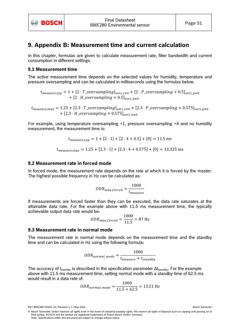
Final Datasheet
BME280 Environmental sensor Page 51
BST-BME280-DS001-10 | Revision 1.1 | May 2015 Bosch Sensortec
© Bosch Sensortec GmbH reserves all rights even in the event of industrial property rights. We reserve all rights of disposal such as copying and passing on to
third parties. BOSCH and the symbol are registered trademarks of Robert Bosch GmbH, Germany.
Note: Specifications within this document are subject to change without notice.
9. Appendix B: Measurement time and current calculation
In this chapter, formulas are given to calculate measurement rate, filter bandwidth and current consumption in different settings.
9.1 Measurement time
The active measurement time depends on the selected values for humidity, temperature and pressure oversampling and can be calculated in milliseconds using the formulas below.
For example, using temperature oversampling ×1, pressure oversampling ×4 and no humidity measurement, the measurement time is:
9.2 Measurement rate in forced mode
In forced mode, the measurement rate depends on the rate at which it is forced by the master. The highest possible frequency in Hz can be calculated as:
If measurements are forced faster than they can be executed, the data rate saturates at the attainable data rate. For the example above with 11.5 ms measurement time, the typically achievable output data rate would be:
9.3 Measurement rate in normal mode
The measurement rate in normal mode depends on the measurement time and the standby time and can be calculated in Hz using the following formula:
The accuracy of tstandby is described in the specification parameter Δtstandby. For the example above with 11.5 ms measurement time, setting normal mode with a standby time of 62.5 ms would result in a data rate of:

Final Datasheet
BME280 Environmental sensor Page 52
BST-BME280-DS001-10 | Revision 1.1 | May 2015 Bosch Sensortec
© Bosch Sensortec GmbH reserves all rights even in the event of industrial property rights. We reserve all rights of disposal such as copying and passing on to
third parties. BOSCH and the symbol are registered trademarks of Robert Bosch GmbH, Germany.
Note: Specifications within this document are subject to change without notice.
9.4 Response time using IIR filter
When using the IIR filter, the response time of the sensor depends on the selected filter coefficient and the data rate used. It can be calculated using the following formula:
For the example above with a data rate of 13.51 Hz, the user could select a filter coefficient of 8. According to Table 6, the number of samples needed to reach 75% of a step response using this filter setting is 11. The response time with filter is therefore:
9.5 Current consumption
The current consumption depends on the selected oversampling settings, the measurement rate and the sensor mode, but not on the IIR filter setting. It can be calculated as:
Note that the only difference between forced and normal mode current consumption is that the current for the inactive time is either IDDSL or IDDSB. For the example above, the current would be
Final Datasheet
BME280 Environmental sensor Page 53
BST-BME280-DS001-10 | Revision 1.1 | May 2015 Bosch Sensortec
© Bosch Sensortec GmbH reserves all rights even in the event of industrial property rights. We reserve all rights of disposal such as copying and passing on to
third parties. BOSCH and the symbol are registered trademarks of Robert Bosch GmbH, Germany.
Note: Specifications within this document are subject to change without notice.
10. Legal disclaimer
10.1 Engineering samples
Engineering Samples are marked with an asterisk (*) or (e) or (E). Samples may vary from the valid technical specifications of the product series contained in this data sheet. They are therefore not intended or fit for resale to third parties or for use in end products. Their sole purpose is internal client testing. The testing of an engineering sample may in no way replace the testing of a product series. Bosch Sensortec assumes no liability for the use of engineering samples. The Purchaser shall indemnify Bosch Sensortec from all claims arising from the use of engineering samples.
10.2 Product use
Bosch Sensortec products are developed for the consumer goods industry. They may only be used within the parameters of this product data sheet. They are not fit for use in life-sustaining or security sensitive systems. Security sensitive systems are those for which a malfunction is expected to lead to bodily harm or significant property damage. In addition, they are not fit for use in products which interact with motor vehicle systems. The resale and/or use of products are at the purchaser’s own risk and his own responsibility. The examination of fitness for the intended use is the sole responsibility of the purchaser. The purchaser shall indemnify Bosch Sensortec from all third party claims arising from any product use not covered by the parameters of this product data sheet or not approved by Bosch Sensortec and reimburse Bosch Sensortec for all costs in connection with such claims. The purchaser must monitor the market for the purchased products, particularly with regard to product safety, and inform Bosch Sensortec without delay of all security relevant incidents.
10.3 Application examples and hints
With respect to any examples or hints given herein, any typical values stated herein and/or any information regarding the application of the device, Bosch Sensortec hereby disclaims any and all warranties and liabilities of any kind, including without limitation warranties of non-infringement of intellectual property rights or copyrights of any third party. The information given in this document shall in no event be regarded as a guarantee of conditions or characteristics. They are provided for illustrative purposes only and no evaluation regarding infringement of intellectual property rights or copyrights or regarding functionality, performance or error has been made.
10.4 Handling Instructions
Detailed handling instructions are described in the document “handling, soldering & mounting instructions (HSMI)”. Important to highlight is the directive to avoid during manufacturing, transport and usage of the sensor in devices the contact of high concentration of chemical solvents and long exposure times. Chemical interactions of chemical compounds with the sensor shall be prevented. These are especially outgassing of corrugated plastic, organic glues, sticky tape made with adhesives, labels, marker or outgassing package materials such as bubble wrap, foams and others shall be avoided. It is recommended to ventilate the production and manufacturing area.
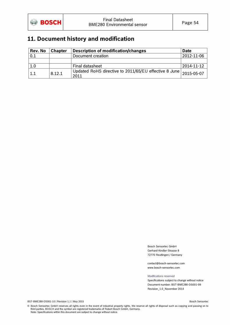
Final Datasheet
BME280 Environmental sensor Page 54
BST-BME280-DS001-10 | Revision 1.1 | May 2015 Bosch Sensortec
© Bosch Sensortec GmbH reserves all rights even in the event of industrial property rights. We reserve all rights of disposal such as copying and passing on to
third parties. BOSCH and the symbol are registered trademarks of Robert Bosch GmbH, Germany.
Note: Specifications within this document are subject to change without notice.
11. Document history and modification
Rev. No Chapter Description of modification/changes Date
0.1 Document creation 2012-11-06
1.0 Final datasheet 2014-11-12
1.1 8.12.1 Updated RoHS directive to 2011/65/EU effective 8 June 2011
2015-05-07
Bosch Sensortec GmbH
Gerhard-Kindler-Strasse 8
72770 Reutlingen / Germany
www.bosch-sensortec.com
Modifications reserved
Specifications subject to change without notice
Document number: BST-BME280-DS001-09
Revision_1.0_November 2014