Embed Size (px)
Citation preview

BLOW MOULDING CONTROLS LTD
LEAK TESTING COURSE NOTES

LEAK TESTING
INDEX
SECTION 1 WHERE DO HOLES COME FROM?
SECTION 2 METHODS OF LEAK DETECTION
SECTION 3 WHAT SIZE HOLE CAN BE DETECTED?
SECTION 4 PRINCIPLES OF PRESSURE DECAY
SECTION 5 TYPICAL PRESSURE DECAY TEST SEQUENCE
SECTION 6 USE OF TEST BOTTLES
SECTION 7 TYPICAL PRESSURE DECAY TEST SEQUENCE
SECTION 8 OTHER OPTIONAL TESTS
SECTION 9 THE PLASMA LEAK DETECTOR
SECTION 10 TECHNICAL SPECIFICATIONS
SECTION 1
WHERE DO HOLES COME FROM?
Holes are produced in containers from various sources, but the number one reason is
contamination. This can be from the raw material or degraded plastic inside the
machine. However, the most likely explanation comes from the regrind which is
blended with virgin material and masterbatch. Regrind is an inherent part of extrusion
blow moulding but should be regarded as necessary evil.
When the excess flash or top and tail scrap is granulated, there is a potential opportunity
for contamination to enter the recycling system. This can be bits of paper, cardboard,
cloth, chipped granulator blade, pens, keys, coins, nuts and bolts, cigarettes, tools - the
list is endless!
Although most blow moulders have magnets in the hopper, the non-metallic items still
pass down the extruder and form part of the parison. When the blow air forms the
container, the particles may manifest itself as a hole.
Ideally no regrind should be used, however this is not practical due to the polymer cost
implications. Typically 20-30% flash is generated on every container, therefore 20-30%
of the mix is regrind. Only companies involved in high risk products i.e.
pharmaceuticals have the luxury of 100% virgin materials handling and waste
management system coupled with good housekeeping.
Burnt or degraded polymer can also cause holes by periodically breaking away from the
internal surface of the head or die and pin. This may form a hole when the parison is
inflated. Heat sensitive materials such as PVC are particularly vulnerable to
degradation.
Virgin material has also been found in the past to contain contaminants such as metal
and insects. This is fairly unusual as most material suppliers take great care when
producing the granules.
The other major explanation for holes is the mould or deflashing problems. If the
mould closing speed is too fast a split may occur in the weld of the container, or if a
mould that has sections is not rebuilt completely flush, then a pin hole leak may
develop. This hole would normally be undetected by the human eye. Once the
container has been blown, it may be deflashed automatically, holes can be created if the
punch is not aligned correctly. Handled containers are the most likely to have this type
of fault.
So now we know what causes the holes, all we have to do now is find them!

SECTION 2
METHODS OF LEAK DETECTION
There are various ways to test a container for leaks. The most common is pressure
decay and is explained in some depth after a brief word on the other methods available.
Vacuum
Instead of using internal pressure, a vacuum can be applied. Although this has the slight
advantage of pulling the test seal onto the bottle, most mouldings are designed to
withstand internal not external pressure so container collapse is quite possible.
Tracer Gas
Various gases e.g. Helium, Freon, Ammonia etc. can easily be detected in very small
concentrations by electronic sensors. By pressurising the moulding with air/tracer gas
mix, small leaks can be detected with the electronic sniffer.
This method is ideal for large containers e.g. 220 litre steel drums, particularly when the
likely leakage points are known, usually on the welded seam.
This technique is also good for automobile petrol tanks as 99.9% of all leaks are on the
filler and fuel sender attachments.
Ultrasonic Sound
Instead of pressurising tracer gas, the ultrasonic sound method fills the container with
noise. An ultrasonic sensor turned to the ultrasonic frequency - usually about 40khz is
then scanned over the outside surface. Any leak will let out the noise. This system has
not been widely adopted in Europe. One problem is that the world we live in is rich in
noise of all frequencies and some of these can accidentally trip the ultrasonic sensor. In
particular ultrasonic welding equipment can interfere with ultrasonic leak testers at great
distances.
Bubbles Under Water
Immersing a pressurised container under water is still one of the most accurate and
reliable methods of finding leaks. Although virtually all modern leak testers use the
pressure decay method, none can find holes as small as the bubble method. The
human eye/brain combination has not been matched by any technology when it comes
to spotting tiny bubbles forming. It can sometimes be very useful to see where the leak
is, as in the case of steel petrol cans, as the leak can be brazed over. Unlike electronic
pressure decay systems that reject the moulding regardless of where the leak is, human
operators can ignore leaks caused by a poorly fitting test seal. With all these points in
mind, the old fashioned bubbles under water method should not be underestimated.

Pressure Decay Method
This is by far the most popular and accepted method. Most leak testers work on the
‘pressure decay’ principle i.e. the moulding is pressurised usually to a very low
pressure. This pressure is measured and any decay beyond a set limit causes the
moulding to be rejected.
(Also see section 4)
Electrical Methods (Voltage Discharge)
The container under test is surrounded by a conductive mask. Then a special probe is
lowered into the container and a high voltage pulse of over 90 thousand volts is
applied. These electrons are strongly attracted to the outer conductive shield and will
find their way even through micron sized holes. These are easily detected by measuring
the current flow from the probe.
(Also see section 9)
SECTION 3
WHAT SIZE HOLE CAN BE DETECTED?
Leak tester manufacturers are constantly being asked “How small a hole can you find?”
Because of many factors there is not a straight forward answer. The main limitations to
finding very small holes is the cycle time available, the bottle capacity and the stiffness
of the bottle.
There are other variables such as bottle temperature, ambient temperature and pressure,
but these can be ignored for the present.
The biggest restriction to setting a leak tester to ultra sensitivity is probably the variable
stiffness of the bottle.
If a series of 5 good bottles are pressurised to the same pressure e.g. 0.5 psi, after 10
seconds the pressure will have fallen to .485 .473 .464 .427 .459. Consequently the
leak tester will need to be set to accept pressures higher than the lowest pressure .427
psi, otherwise this ‘good bottle’ will have been rejected.
It can be clearly seen that it is not practical to set the reject level at 99.9% of fill pressure
otherwise all good bottles will be rejected.
As we all imagine, a perfectly set leak tester in prefect conditions with a small capacity
still bottle, would yield good impressive results. Unfortunately anyone who lives in the
real world will accept that their factory test conditions are less than perfect and your
engineers have better things to do than play with leak tester settings all day.
Leak tester manufacturers who claim to find smaller holes than anyone else’s usually
end up de-sensitising their leak testers to prevent an unacceptable reject rate of good
bottles.
Most good leak testers will find a 0.1mm hole reliably in a 1 litre bottle in 7 seconds.
Holes smaller than this probably only constitute 1 in 1000 holes and with good
housekeeping, perhaps only 1 in 1000 bottles has any hole. Thus it is feasible to
imagine only 1 bottle in a million get shipped with a hole.
Filling companies don’t generally mind 1 leaker in a million. Its the bottles with 2cm
holes that stop the filling line every 15 minutes that drive them crazy!
If it is essential to find very, very, small holes there are various solutions:-
a) Test bottles when they are colder by using longer conveyors or accumulating
tables before the leak tester.
b) Hold bottles in a purpose designed nest to ensure exactly repeatable positioning.
c) Prevent air-line fluctuations by fitting a local air receiver.
d) Have a properly calibrated test hole fitted to a sample bottle and run it through
the leak tester at least once an hour.
e) Lock the adjustments from unskilled operatives.
On Blow Moulding Controls leak testers, the threshold or reject pressure % is factory set
at 80%. This means that containers that retain less than 80% of the original pressure
will be rejected.
This works very well and will detect medium and large holes. However a container
with a very small hole may retain a pressure about 80% and be passed. To prevent this
the unit should be find tuned so that the reject pressure % is 2% below the lowest
measured final pressure % (test result). This can be done by monitoring the final
pressure % on containers passing through the unit. If the unit is set in this way, the
smallest possible holes will be found. If this appears to be rejecting good containers,
make sure they are good and then adjust the reject pressure % so it is 2% below the
current measured final pressure %.
As already stated, the other limitation is the test time available. This has to be short
enough, so that containers don’t queue back into the blow moulder causing a jam up.
However, the more test time available, the more credible the test., The graphs on the
following pages show the correlation between container size, output rate and detectable
hole size.
If the output rate of the blow moulder exceeds 1800 1 litre bottles per hour, a twin or
quadruple test head must be used. A twin test head unit can cope with 2400 containers
per hour and a quad 3200 per hour assuming a 1 litre bottle.
On very large containers it is necessary to have a longer test time. This is possible due
to the long blowing time (2-3 minutes on a 220 litre drum). This means a 0.3mm hole
can be found using the two or three minutes available.
To find holes of 30 micron or less, pressure decay can non longer be used. Blow
Moulding Controls have developed the Plasma Leak Detector which eventually aims to
detect holes of a few microns. The process in explained in section 9.

HOLE DIAMETER AGAINST THROUGHPUT
FOR VARIOUS BOTTLE SIZES

HOLE DIAMETER AGAINST THROUGHPUT
FOR VARIOUS MOULDING SIZES
SECTION 4
PRINCIPLES OF PRESSURE DECAY
This is by far the most popular and accepted method. Most leak testers work on this
method.
i.e. The moulding is pressurised to a low pressure. This pressure is measured, any
decay beyond a set limit causes the moulding to be rejects. If the moulding was rigid
and leak tight and we lived in a perfect world, the pressure profile would look like
figure 1 (at the end of this section). This would enable a very close limit to be set on a
Pass/Fail level.
In real life many other factors come into play which reduce the repeatability of this test
principle. A real life profile is shown in figure 2 (at the end of this section).
The four main contributory factors to this problem are:-
1) Overshoot due to switching time of pneumatic valve.
2) Change air heated by compression loses heat quickly and creates a small
pressure drop.
3) A gradual decay in pressure due to the creep effect of plastic i.e. the container
stretches in shape slowly with internal pressure.
4) Mechanical vibrations translate into pressure noise. A pressure transducer is a
microphone!
Over the years, various techniques have been employed to sense the pressure decay.
Initially, pressure switches are used but these have rarely been abandoned because of
the poor sensitivity and drift caused by the mechanical hysteresis.
‘Balanced’ systems use a differential pressure transducer placed between the bottle on
test and a reference container. Inevitably the reference container does not truly mimic
the temperature or stiffness of the bottle under test.
BMC leak testers work by initially pressurising the container under test with air, then
monitoring the pressure within the container for the remainder of the test time. The
percentage of air remaining at the end of the test is used to determine the test result.
One thing all pressure decay leak testers need is clean, dry air supplied from a
consistent source.

FIGURE 1

FIGURE 2
SECTION 5
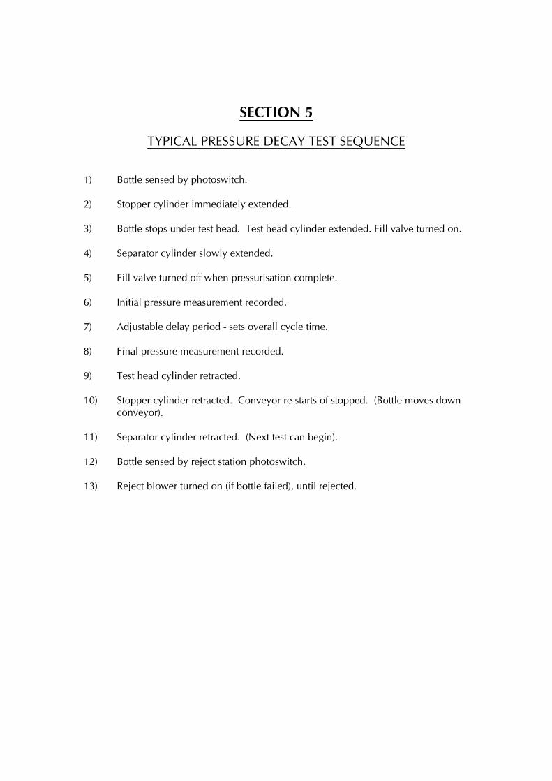
TYPICAL PRESSURE DECAY TEST SEQUENCE
1) Bottle sensed by photoswitch.
2) Stopper cylinder immediately extended.
3) Bottle stops under test head. Test head cylinder extended. Fill valve turned on.
4) Separator cylinder slowly extended.
5) Fill valve turned off when pressurisation complete.
6) Initial pressure measurement recorded.
7) Adjustable delay period - sets overall cycle time.
8) Final pressure measurement recorded.
9) Test head cylinder retracted.
10) Stopper cylinder retracted. Conveyor re-starts of stopped. (Bottle moves down
conveyor).
11) Separator cylinder retracted. (Next test can begin).
12) Bottle sensed by reject station photoswitch.
13) Reject blower turned on (if bottle failed), until rejected.

SECTION 6
USE OF TEST BOTTLE
Most companies who have leak testers use a test bottle. This is to check the test unit is
finding leaks of a known size. However, relying on the same test bottle can be a recipe
for disaster.
This is because eventually the test bottle passes through as a good bottle. This is due to
the way the test hole was made. If a craft knife was used, the hole is a flap really, which
closes together. Even a hole made with a cold pin will close up especially if oil and
grease are rubbed onto the container from peoples dirty fingers.
A better way to make a test hole is to use a hot pin of a known size, this hole is less
likely to close together.
The only way of creating a true test hole is by using a metal disc with a known size hole
fitted in to the wall of the moulding . As long as this container is not granulated! It is
the best way of using a test bottle.

SECTION 7
SETTING FAULTS
The two worst scenarios are:-
1) Bad containers being passed.
2) Good containers being failed.
Blow Moulding Controls leak testers work on the pressure decay principle. This means
that the containers are pressurised with low pressure air, an initial reading taken and
then following a variable test time a pressure percentage has fallen below a pre-
determined level, the container will be rejected.
This variable reject can be described as the reject pressure percentage or reject
threshold. Therefore if the reject percentage is set too low to detect the hold size
required, the leak tester will be fooled into thinking it is OK and pass it. This is why,
when a new product is set up, the reject pressure percentage should be fine tuned to
ensure the smallest hole possible will be found. This is normally 2 or 3 % below the
consistent measured final pressure percentage setting. Therefore all containers would
be considered failures.
The other main reason is poor or intermittent sealing. This is either incorrect top load,
stroke setting or unsuitable seal material. This covers point 2. (See also poor neck seal
and top load setting).
Overfilling
Another common mistake is to overfill the container, which results in all mouldings
being rejected. The fill rate should be set to a value equal to 1 bar per litre of container
volume, upto a maximum of 4 bar. The bargraph should operate just up into the green
section, if the overfill occurs the overfill LED will light. If the fill rate is too low , the test
time will be unnecessarily long.
Photoswitches
The photoswitches used are diffuse reflective types with adjustable sensitivity. These
work well with most bottles. However, problems are occasionally encountered with
transparent shiny bottles or matt black ones. In these cases, the photoswitch sensitivity
should be turned to maximum. An alternative type of photoswitch can be used if this
still causes a problem.
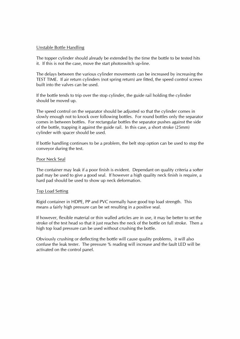
Unstable Bottle Handling
The topper cylinder should already be extended by the time the bottle to be tested hits
it. If this is not the case, move the start photoswitch up-line.
The delays between the various cylinder movements can be increased by increasing the
TEST TIME. If air return cylinders (not spring return) are fitted, the speed control screws
built into the valves can be used.
If the bottle tends to trip over the stop cylinder, the guide rail holding the cylinder
should be moved up.
The speed control on the separator should be adjusted so that the cylinder comes in
slowly enough not to knock over following bottles. For round bottles only the separator
comes in between bottles. For rectangular bottles the separator pushes against the side
of the bottle, trapping it against the guide rail. In this case, a short stroke (25mm)
cylinder with spacer should be used.
If bottle handling continues to be a problem, the belt stop option can be used to stop the
conveyor during the test.
Poor Neck Seal
The container may leak if a poor finish is evident. Dependant on quality criteria a softer
pad may be used to give a good seal. If however a high quality neck finish is require, a
hard pad should be used to show up neck deformation.
Top Load Setting
Rigid container in HDPE, PP and PVC normally have good top load strength. This
means a fairly high pressure can be set resulting in a positive seal.
If however, flexible material or thin walled articles are in use, it may be better to set the
stroke of the test head so that it just reaches the neck of the bottle on full stroke. Then a
high top load pressure can be used without crushing the bottle.
Obviously crushing or deflecting the bottle will cause quality problems, it will also
confuse the leak tester. The pressure % reading will increase and the fault LED will be
activated on the control panel.
SECTION 8
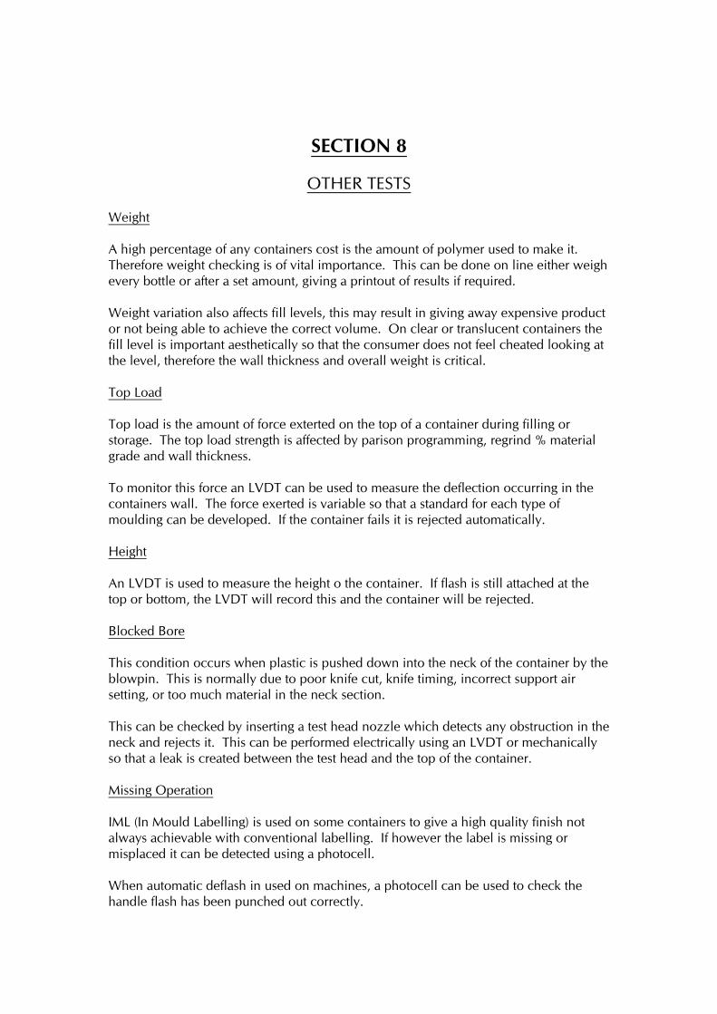
OTHER TESTS
Weight
A high percentage of any containers cost is the amount of polymer used to make it.
Therefore weight checking is of vital importance. This can be done on line either weigh
every bottle or after a set amount, giving a printout of results if required.
Weight variation also affects fill levels, this may result in giving away expensive product
or not being able to achieve the correct volume. On clear or translucent containers the
fill level is important aesthetically so that the consumer does not feel cheated looking at
the level, therefore the wall thickness and overall weight is critical.
Top Load
Top load is the amount of force exterted on the top of a container during filling or
storage. The top load strength is affected by parison programming, regrind % material
grade and wall thickness.
To monitor this force an LVDT can be used to measure the deflection occurring in the
containers wall. The force exerted is variable so that a standard for each type of
moulding can be developed. If the container fails it is rejected automatically.
Height
An LVDT is used to measure the height o the container. If flash is still attached at the
top or bottom, the LVDT will record this and the container will be rejected.
Blocked Bore
This condition occurs when plastic is pushed down into the neck of the container by the
blowpin. This is normally due to poor knife cut, knife timing, incorrect support air
setting, or too much material in the neck section.
This can be checked by inserting a test head nozzle which detects any obstruction in the
neck and rejects it. This can be performed electrically using an LVDT or mechanically
so that a leak is created between the test head and the top of the container.
Missing Operation
IML (In Mould Labelling) is used on some containers to give a high quality finish not
always achievable with conventional labelling. If however the label is missing or
misplaced it can be detected using a photocell.
When automatic deflash in used on machines, a photocell can be used to check the
handle flash has been punched out correctly.

Limitations of On-Line Testing
Due to time and costs constraint, it is difficult to test for:-
Contamination which does not create a hole.
Gas permeability.
Long term shrinkage.
Environmental stress cracking.
Colour acceptance.

SECTION 9
THE PLASMA LEAK DETECTOR
As has been stated in previous sections, most leak testers work on the pressure decay
principle. This principle has some inherent weaknesses, i.e.
1) It relies on a clean, dry consistent air supply.
2) Unreliability due to the warm/hot temperature of the moulding under test.
3) The stretch/dimensional changes that occur when bottles are re-pressurised
during testing.
4) Trying to locate tiny holes inside the cycle time of the blow moulder. Detecting
small holes in large containers.
The disadvantages listed above are not necessarily due to poor leak testing design, but
the physics of gas laws. It is also important to point out that for many applications the
pressure decay methods is perfectly adequate. The concept of plasma leak detection is
to pioneer fast, reliable leak detection of extremely small holes very quickly.
How does the plasma work?
The container under test (see figure 1) is surrounded by a conductive mask which can
be metal or more conveniently in some applications, a conductive plastic foam.
A special probe is lowered into the container and a high voltage pulse of over 90
thousand volts is applied. This has the effect of ‘spraying’ the inside of the container
with a ‘plasma’ of electrons.
These electrons are strongly attracted to the outer conductive shield and will find their
way even through micron sized holes, and are easily detected by measuring the current
flow from the probe.
The advantages of the PLASMA test method are:
1) Very Short Test Time
The leak test itself only takes a couple of milli-seconds regardless of container size. In
other words, it takes no longer to detect a 10 micron hole in a 1000 litre IBC than a 10
micron hole in a 1 litre milk bottle.
2) High Sensitivity Without Instability
Container temperature, size and flexibility are irrelevant to this process. The addition of
anti-static, U.V. inhibitors, masterbatches and post consumer regrind have no noticeable
effect.
3) Immune to Ambient Conditions
Unlike pressure decay leak testers, changes in ambient pressure, temperature, sunlight
and machine vibration do not affect the sensitivity or repeatability of the plasma tester.
4) Area Of Leakage Can Be Located
By separating the conductive mask into segments, we can detect the area of leakage (see
figure 2). It is particularly useful to show if the problem is caused by poor neck finish
handle damage or a poor base weld so that the process can be corrected to prevent the
production of more containers with the same defects.
5) Variable Sensitivity
The ability to sense the location or area of leakage also gives the possibility to adjust the
sensitivity for each area. For example, if neck finish is not critical because of the type of
closure, sensitivity in this area can be reduced. This avoids the common problem of
rejecting containers unnecessarily due to neck surface finish.
6) ‘Thin Wall’ Detection
Although still experimental, we have seen some positive results which indicate that the
plasma tester can detect unusually thin areas of a container. This is due to the increased
electron migration through such an area. More work is needed to make this feature
reliable.
7) Medical and Food Application Friendly
Unlike pressure decay detection methods, the plasma leak tester does not introduce air
into the container. This means it is less likely to introduce contaminants into what is
otherwise a ‘clean’ container.
8) Excellent Repeatability
With pressure decay test methods, the difference in pressure transducer signals from a
good container to one with a small hole is most indistinguishable. This is one of the
main reasons why leak testers frequently reject ‘good’ containers. Their sensitivity is
almost set up to the point of instability. Our ‘plasma’ method testing a 25 litre drum
with a 10 micron hole gives a output signal of 10 volts. A good container about 1/2
volt. Thus the circuitry has no difficulty in detecting good containers from bad.
9) Excellent For High Speed Applications
At present, expensive rotary leak testers are usually required for applications over about
4000 bottles per hour. The new plasma technique does not require a time delay to
measure pressure decay, so our process in inherently much faster.

We are constructing an 8 head in line plasma leak tester which is intended to test
5.0000 to 10,000 bottles per hour. The purpose of this development is to over come
the main disadvantages of rotary leak testers which are:
a) Considerably more expensive than in-line testers.
b) Can be difficult to change over with nests, star wheels, scroll screw etc.
c) Very difficult to adjust test heads whilst rotating.
d) Limited number of suppliers
e) Less flexible in accepting a wide range of container shapes and sizes. For
example, try running 200ml bottles on a rotary tester intended for 2 Lt angled
neck bleach bottles.
10) Containers for Dangerous Chemicals
Companies who produce ‘UN certified’ containers may know that committee CEN227 is
due to consider the subject of on-line leak testing. At present there are no set
performance standards for on-line leak testers and the committee will almost certainly
look at establishing test pressures and minimum size hole specifications. We would be
very surprised if the 0.3mm size hole that has been the ‘unofficial’ pressure decay leak
tester standard will be acceptable to the committee as it would be considered a ‘barn
door’ hole to hazardous chemicals. With this in mind, the first tester we will be
launching will be for 20 to 30 litre UN certified containers, and the second model for
210 litre ‘L’ ring style drums.
These testers will be capable of detecting micron sized holes in test times much faster
than any known pressure decay method.
11) Testing Steel Drums With Plastic Liners
Theoretically, a steel drum fitted with a plastic liner is an ideal method of packaging and
transporting extremely hazardous chemicals. Obviously, this is only true if the
container doesn’t leak!
At present it is common to leak test a blow moulded liner before fitting it into the steel
container. This unfortunately will not show up any leaks caused by damage to the liner
during the fitting process. “Pressure decay” leak testing the container as a complete
package can be done, but holes in the liner can be masked by the liner pressing against
the smooth inside of the steel drum. The steel drum would normally be completely leak
tight and this also prevents the detection of leakage by pressure decay methods.
If the plastic liner leaks, chemicals can attack the lacquered coating and then the steel
itself, so it is obviously important to consider testing the complete assembly. The
plasma test method is ideal for this application because it measures the electron flow
from the inside of the plastic container to any conductive outer surface.
Impending legislation will require drum reconditioners to carry out leak testing. The
Plasma test method will detect hole and stress cracks which may be produced by the
hot caustic washing often used by most reconditioning processes.
We believe that our Plasma leak testers will be the only method that will enable
reconditioners to meet the requirements.
12) P.C.R. And Other Reclaimed Material
Almost by definition, any material other than new virgin stock has an increased risk of
being contaminated.
This contamination can take many forms, from residues of the previous liquids, label
and foil remnants and dirt. Contamination, particularly of a fibrous nature is the biggest,
single cause of all leaks in plastic containers. It follows that using reclaimed material
increases the need for 100% leak testing.
Leak testers operating on the ‘pressure decay’ principle will often not detect ‘moulded
in’ contamination because it effectively acts as a gas seal. Unfortunately, when the
container is filled, fibrous contamination will usually disintegrate and the container will
leak. Although the possibility of leakage is reduced if the reclaimed material is used as a
part of a multi layer extrusion, the wall strength in contaminated areas will be
considerably reduced, so the likely hood of leakage is increased.
Because fibrous contaminants exhibit a very poor dielectric strength, the plasma
detection principle detects fibre filled holes.
Disadvantages Of Plasma Leak Test Method
Cannot be used for steel drums, and may not be suitable for some plastic containers
with moulded in metal inserts.
The container under test must be surrounded by a conductive material which does not
have to be close fitting. Using conductive foam eliminates the need to shape the mask
to each container.
Is Plasma Leak Testing Really New?
Yes, and patented by Blow Moulding Controls Ltd in three critical areas. It has
occasionally been confused with ‘spark testing’ which is not new. Our patent describes
in detail the differences in the two test methods.
The spark testing method has been used for years on fabricated tanks, injection moulded
battery cases, and is also in use in Japan on PET preforms.

Spark testing relies on the ‘brute force’ of a high voltage source placed in close
proximity to the container wall to actually spark through. To be effective, an electrode
has to be shaped to be in close contact with the inside of the container. Obviously
getting such electrodes through the neck, and in contact with recessed areas and inside
handle etc. is very difficult.
Because of the wide variety of limitations we do not consider spark testing suitable for
the vast majority of blow moulding applications.